

Page 1
TECHNICALDATA
Order No. SBPAC1612014CE
GasHeatPump
AirConditioner
2WAYMulti
2WAYWMulti
3WAYMulti
OUTDOORMODELNo.
U-16GE3E5
U-20GE3E5
U-25GE3E5
U-30GE3E5
U-16GF3E5
U-20GF3E5
U-25GF3E5
REFERENCENo.
GTD-1710-01C
Page 2

Page 3

Contents
System Configuration ................................................................... A-1
Outdoor Unit ................................................................................. B-1
Control-Related ............................................................................C-1
System Design .............................................................................D-1
Installation Work ........................................................................... E-1
Separately Sold Parts ..................................................................F-1
Periodic Inspection ....................................................................... G-1
Page 4

Page 5

System Configuration
1. Type Configuration
(1) Outdoor unit ............................................................................................................ A-2
Contents
A-1
Page 6
System Configuration
(1) Outdoor Unit
2WAY W Multi (16, 20, 25 and 30 Horsepower)
3WAY Multi (16, 20 and 25 Horsepower)
1. Type Configuration
U-16GE3E5
U-20GE3E5
U-25GE3E5
U-30GE3E5
U-16GF3E5
U-20GF3E5
U-25GF3E5
A-2
Page 7

Outdoor Unit
Contents
1. Gas Usage Conditions
(1) Usable Gas ............................................................................................................. B-2
(2) Gas Supply Pressure .............................................................................................. B-2
(3) Applicable Gas Type ................................................................................................ B-2
(4) Gas Maximum Flow Volume .................................................................................... B-2
(5) When using Propane .............................................................................................. B-3
2. Specifications......................................................................................................B-4
3. External Dimensions ...........................................................................................B-11
4. Wiring Diagram ...................................................................................................B-15
5. Performance Characteristics...............................................................................B-16
6. Vibration Force
(1) Measurement Points ............................................................................................... B-36
(2) Vibration Force ........................................................................................................ B-36
B-1
Page 8
Outdoor Unit
1. Gas Usage Conditions
(1) Usable Gas
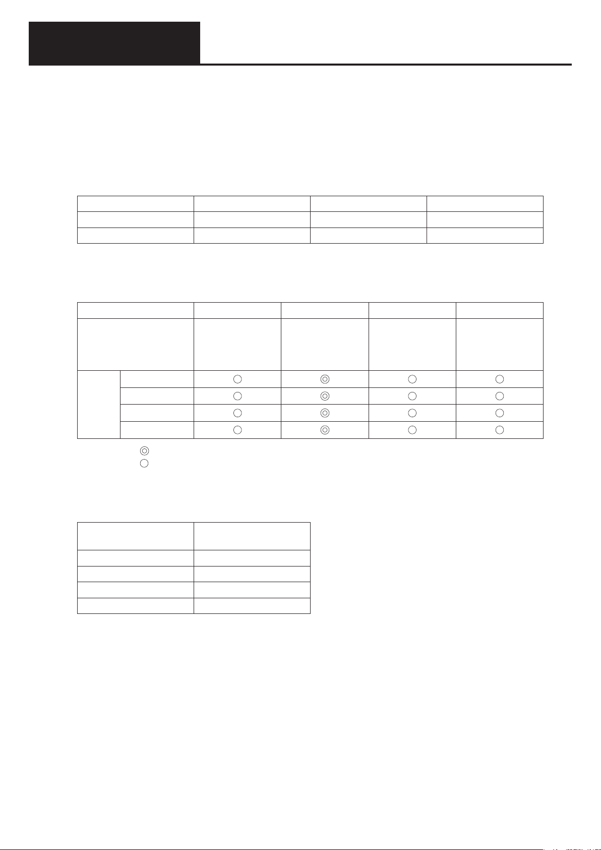
Depending upon the calorific value of the natural gas, the setting for the gas fuel flow rate adjustment
nozzle will differ.
* If the gas type changes due to relocation or fuel conversion, gas type setting is required.
(2) Gas Supply Pressure
Units: mbar
Gas Type Maximum Standard Minimum
P 45 37 25
H, L, E 25 20 17
(3) Applicable Gas Type
Group P H L E
Gas composition
Standard gas
Calorific value
(MJ/m
45.0 kW Type
Model
Name
56.0 kW Type
71.0 kW Type
85.0 kW Type
3
N)
C3H8 100%
G31
95.65
CH4 100%
G20
37.78
CH4 86% N2 14%
G25
32.49
CH4 100%
G20
37.78
Applicability : Standard setting when shipped from the factory
: Necessary to change the gas type setting on site
(4) Gas Maximum Flow Volume
Outdoor unit type
45.0 kW 57
56.0 kW 69
71.0 kW 80
85.0 kW 90
The gas maximum flow volume is the quantity of gas consumed after start up and operating at full capacity,
with the gas at 40 °C and at standard pressure.
Gas Maximum Flow
Volume (kW)
B-2
Page 9
Outdoor Unit
1. Gas Usage Conditions
(5) When using Propane
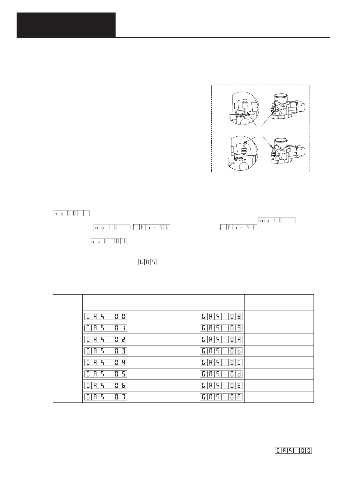
* When using Propane as the gas fuel, it is necessary to adjust the fuel adjustment valve and the gas
type setting.
(1) Fuel valve setting
With the power supply breaker for the outdoor unit OFF
1) Move the lever of the P/N switch that is attached to the mixer
part of the engine to the position shown in the diagram. Turn
it 180 degrees in the clockwise direction (there is a stopper
provided). Do not apply unnecessary force to turn it any
further.
2) Attach the short-circuit connector supplied to the N/P switch
CN013 on the outdoor unit’s control board.
* Switch the outdoor unit’s power breaker to ON.
3) In the electrical equipment box, fix the "Gas type setting/
Adjustment Completed" label to the prescribed position for
the PL NAME.
(2) Fuel Gas Type Setting
H•L•E
P
Lever
Check that the fuel adjustment valve setting has been set before operating the outdoor control board.
1) Press the home key (SW004) for longer than one second and the menu item number will be displayed.
2) Next, press the up (SW005)/down (SW006) key to set the menu item number to .
3) After displaying , is displayed. When is displayed press the
set (SW007) key. The green LED (LED053) lights up, and the system address setting is displayed.
(For example: )
4) Next operate the down (SW006)/up (SW005) key, to display the gas type setting. When the gas type
setting is displayed, press the set (SW007) key for longer than one second.
Note: When setting the gas type, ** is displayed.(for ** enter 00-05)
5) A red LED (LED052) lights up, indicating that a forced setting is being carried out. In this condition, press
the down (SW006)/up (SW005) key, and select the gas type.
The relationship between display and gas type is as shown in the following table.
↑ DOWN
↓ UP
Status/setting
display
Type of gas
Band P (LPG) No Use
No Use No Use
Band H/L (Natural Gas) No Use
No Use No Use
Band E (Natural Gas) No Use
Status/setting
display
Type of gas
No Use No Use
No Use Band LNG (Natural Gas)
No Use No Use
* When the H/L/E gas type is selected, the oil replacement time warning is not displayed.
6) After completing selection of gas type, press the set (SW007) key for longer than 1 second. The red
LED (LED052) will be extinguished.
7) Press the home (SW004) key to complete the setting.
Note: When using propane, change the setting in accordance with the above procedure to
B-3
Page 10
Outdoor Unit
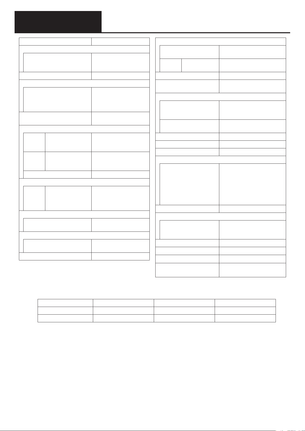
2. Specifications
Model No. U-16GE3E5
External dimensions (mm)
Height
Width
Depth
Weight (kg) 765
Performance (kW)
Cooling capacity
Heating capacity (Standard)
Heating capacity (low temp.)
Hot Water (Cooling mode)
Generate electricity power source
Electrical rating
Running amperes (A)
Cooling
Heating
Starting amperes (A) 30
Gas Type
Gas Band
Gas consumption (kW)
Compressor
Cooling oil (L) (type)
Crankcase heater (W)
Paint color (Munsell code) Silky Shade (1Y8.5/0.5)
Power input (kW)
Power factor (%)
Running amperes (A)
Power input (kW)
Power factor (%)
P
H
L
E
Cooling
Heating (Standard)
23.6 (@65°C outlet)
2,255
1,650
1,000 (+80)
45.0
50.0
53.0
(Note 7)
220 to 240 V, 50 Hz,
Single-phase
5.35
1.17
95
2.71
0.56
90
Propane gas (G31)
Natural gas (G20)
Natural gas (G25)
Natural gas (G20)
41.1
38.0
4.4 (HP-9)
30
Engine
Displacement (L)
Rated output (kW)
Oil
Starter motor 12 V DC, 2.0 kW
Starter type
Engine cooling water
Quantity (L)
Concentration, Freezing
temperature
Cooling water pump rated
output (kW)
Refrigerant type, Quantity (kg) HFC [R410A] , 11.5
Air intakes Front and Rear side
Air outlet To p
Piping
Refrigerant gas (mm)
Refrigerant liquid (mm)
Exhaust drain (mm)
Hot water supply in/out
Operating noise level dB(A) 80/60 (PWL/SPL)
Ventilation System
Air flow rate (m
Rated output (kW)
Drain heater (W) 40
Quantity (L)
Fuel gas
Type
Type
3
/min)
AC/DC conversion type DC
ø25 .Rubber hose (length: 350)
2.488
10.0
Panasonic Genuine
40
starter
21
50 V/V%, –35°C
0.16
ø28.58(brazed)
(ø31.75) (Note 4)
ø12.7(brazed)
(ø15.88) (Note 4)
R3/4 (Bolt, thread)
Rp3/4 (Nut, thread)
Propeller fans (x2)
370
0.70×2
SEER 1.98
SCOP 1.36
Design Pressure
(HP/LP) (MPa)
4.15/2.5
Notes
1. Cooling and heating capacities in the tables are determined under the test conditions of JIS B 8627.
Operating condition Cooling Heating (standard) Heating (low temp.)
Indoor air intake temp. 27°CDB/19°CWB 20°CDB 20°CDB/15°CWB or less
Outdoor air intake temp. 35°CDB 7°CDB/6°CWB 2°CDB/1°CWB
• Effective heating requires that the outdoor air intake temperature be at least –20°CDB or –21°CWB.
2. Gas consumption is the total (high) calorific value standard.
3. Outdoor unit operating sound is measured 1 meter from the front and 1.5 meters above the floor (in an
anechoic environment). Actual installations may have larger values due to ambient noise and reflections.
4. Values in parentheses ( ) for refrigerant gas and liquid types are those when the maximum piping length
exceeds 90 meters (equivalent length). (Reducers are available locally.)
5. Specifications are subject to change without notice.
6. Hot water heating capacity is applicable during cooling operation as in Note 1.
7. The maximum water temperature that can be obtained is 65°C. Water heating performance and temperature
vary with the air conditioning load.
Because the hot water heating system uses waste heat from the engine, which runs the air conditioning,
its ability to heat water is not guaranteed.
B-4
Page 11
Outdoor Unit
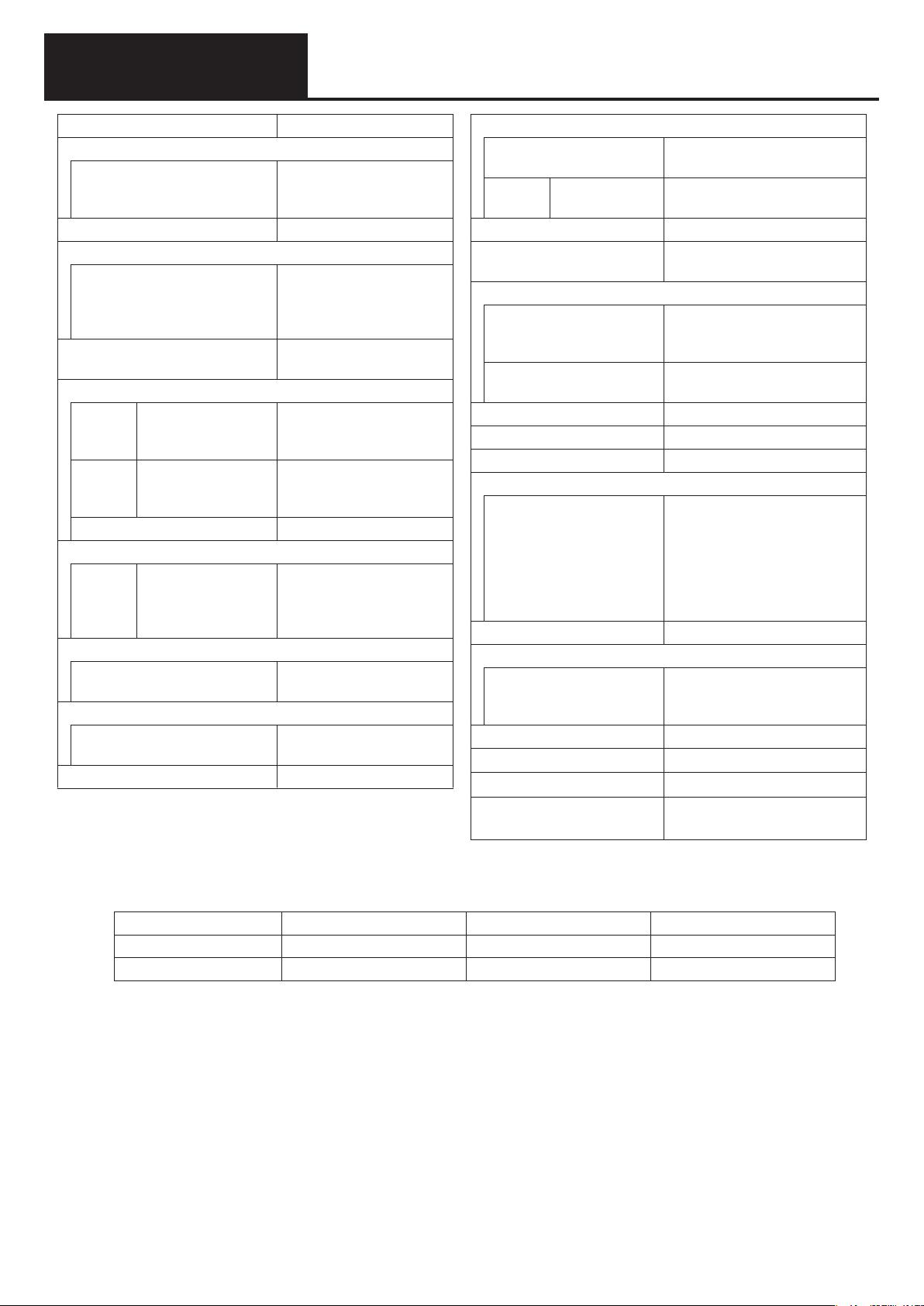
2. Specifications
Model No. U-20GE3E5
External dimensions (mm)
Height
Width
Depth
Weight (kg) 765
Performance (kW)
Cooling capacity
Heating capacity (Standard)
Heating capacity (low temp.)
Hot Water (Cooling mode)
Generate electricity power source
Electrical rating
Running amperes (A)
Cooling
Heating
Starting amperes (A) 30
Gas Type
Gas Band
Gas consumption (kW)
Compressor
Cooling oil (L) (type)
Crankcase heater (W)
Paint color (Munsell code) Silky Shade (1Y8.5/0.5)
Power input (kW)
Power factor (%)
Running amperes (A)
Power input (kW)
Power factor (%)
P
H
L
E
Cooling
Heating (Standard)
29.1 (@65°C outlet)
2,255
1,650
1,000 (+80)
56.0
63.0
67.0
(Note 7)
220 to 240 V, 50 Hz,
Single-phase
5.18
1.12
94
4.79
1.05
95
Propane gas (G31)
Natural gas (G20)
Natural gas (G25)
Natural gas (G20)
52.1
51.1
4.4 (HP-9)
30
Engine
Displacement (L)
Rated output (kW)
Oil
Starter motor 12 V DC, 2.0 kW
Starter type
Engine cooling water
Quantity (L)
Concentration, Freezing
temperature
Cooling water pump rated
output (kW)
Refrigerant type, Quantity (kg) HFC [R410A] , 11.5
Air intakes Front and Rear side
Air outlet To p
Piping
Refrigerant gas (mm)
Refrigerant liquid (mm)
Exhaust drain (mm)
Hot water supply in/out
Operating noise level dB(A) 80/60 (PWL/SPL)
Ventilation System
Air flow rate (m
Rated output (kW)
Drain heater (W) 40
Quantity (L)
Fuel gas
Type
Type
3
/min)
AC/DC conversion type DC
ø25 .Rubber hose (length: 350)
2.488
12.4
Panasonic Genuine
40
starter
21
50 V/V%, –35°C
0.16
ø28.58(brazed)
(ø31.75) (Note 4)
ø15.88(brazed)
(ø19.05) (Note 4)
R3/4 (Bolt, thread)
Rp3/4 (Nut, thread)
Propeller fans (x2)
420
0.70×2
SEER 1.90
SCOP 1.33
Design Pressure
(HP/LP) (MPa)
4.15/2.5
Notes
1. Cooling and heating capacities in the tables are determined under the test conditions of JIS B 8627.
Operating condition Cooling Heating (standard) Heating (low temp.)
Indoor air intake temp. 27°CDB/19°CWB 20°CDB 20°CDB/15°CWB or less
Outdoor air intake temp. 35°CDB 7°CDB/6°CWB 2°CDB/1°CWB
• Effective heating requires that the outdoor air intake temperature be at least –20°CDB or –21°CWB.
2. Gas consumption is the total (high) calorific value standard.
3. Outdoor unit operating sound is measured 1 meter from the front and 1.5 meters above the floor (in an
anechoic environment). Actual installations may have larger values due to ambient noise and reflections.
4. Values in parentheses ( ) for refrigerant gas and liquid types are those when the maximum piping length
exceeds 90 meters (equivalent length). (Reducers are available locally.)
5. Specifications are subject to change without notice.
6. Hot water heating capacity is applicable during cooling operation as in Note 1.
7. The maximum water temperature that can be obtained is 65°C. Water heating performance and temperature
vary with the air conditioning load.
Because the hot water heating system uses waste heat from the engine, which runs the air conditioning,
its ability to heat water is not guaranteed.
B-5
Page 12
Outdoor Unit
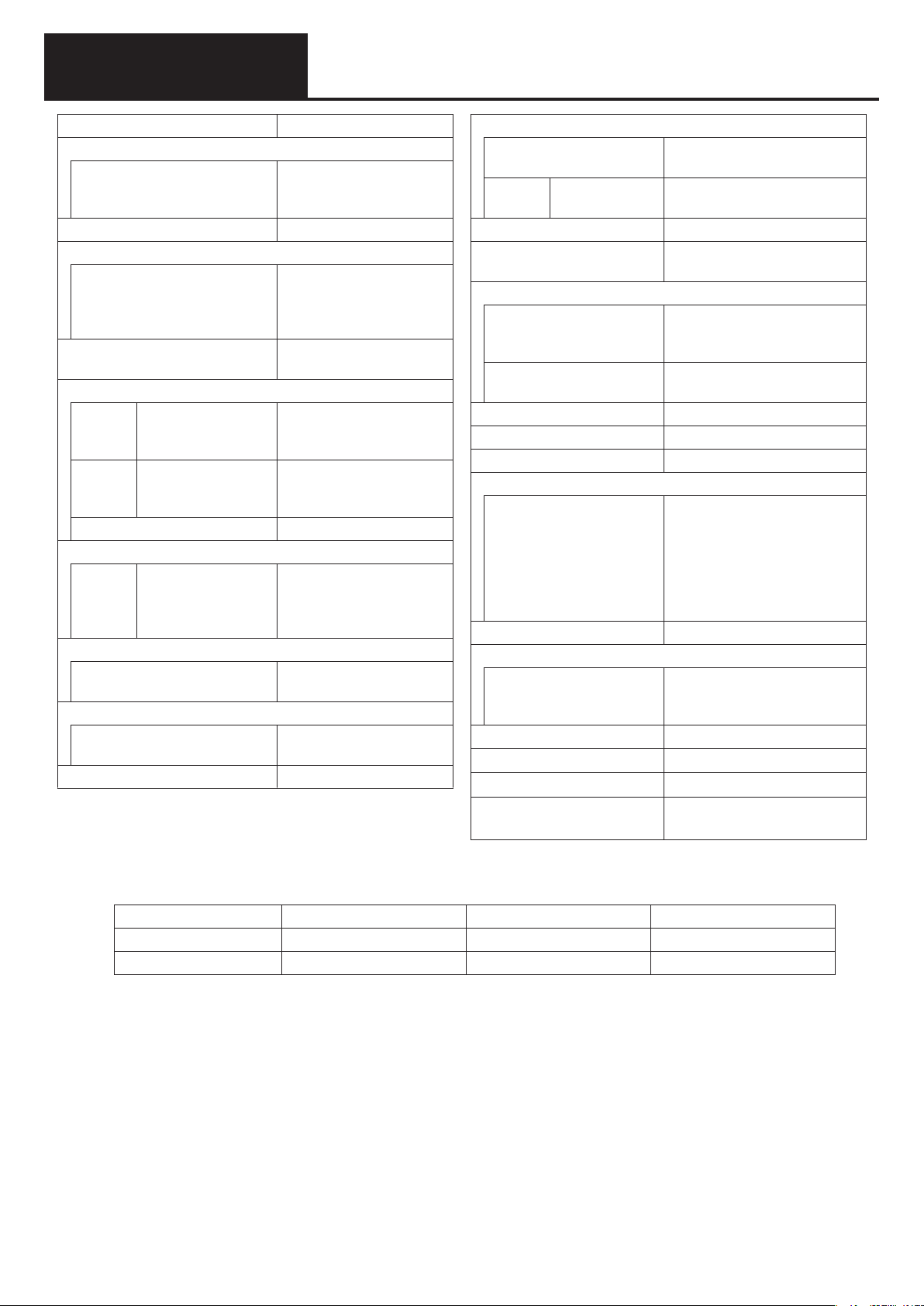
2. Specifications
Model No. U-25GE3E5
External dimensions (mm)
Height
Width
Depth
Weight (kg) 870
Performance (kW)
Cooling capacity
Heating capacity (Standard)
Heating capacity (low temp.)
Hot Water (Cooling mode)
Generate electricity power source
Electrical rating
Running amperes (A)
Cooling
Heating
Starting amperes (A) 30
Gas Type
Gas Band
Gas consumption (kW)
Compressor
Cooling oil (L) (type)
Crankcase heater (W)
Paint color (Munsell code) Silky Shade (1Y8.5/0.5)
Power input (kW)
Power factor (%)
Running amperes (A)
Power input (kW)
Power factor (%)
P
H
L
E
Cooling
Heating (Standard)
36.4 (@65°C outlet)
2,255
2,026
1,000 (+80)
71.0
80.0
78.0
(Note 7)
220 to 240 V, 50 Hz,
Single-phase
8.39
1.80
93
4.16
0.91
95
Propane gas (G31)
Natural gas (G20)
Natural gas (G25)
Natural gas (G20)
67.2
68.6
5.0 (HP-9)
30
Engine
Displacement (L)
Rated output (kW)
Oil
Starter motor 12 V DC, 2.0 kW
Starter type
Engine cooling water
Quantity (L)
Concentration, Freezing
temperature
Cooling water pump rated
output (kW)
Refrigerant type, Quantity (kg) HFC [R410A] , 11.5
Air intakes Front and Rear side
Air outlet To p
Piping
Refrigerant gas (mm)
Refrigerant liquid (mm)
Exhaust drain (mm)
Hot water supply in/out
Operating noise level dB(A) 84/64 (PWL/SPL)
Ventilation System
Air flow rate (m
Rated output (kW)
Drain heater (W) 40
Quantity (L)
Fuel gas
Type
Type
3
/min)
AC/DC conversion type DC
ø25 .Rubber hose (length: 350)
2.488
15.7
Panasonic Genuine
46
starter
27
50 V/V%, –35°C
0.16
ø28.58(brazed)
(ø31.75) (Note 4)
ø15.88(brazed)
(ø19.05) (Note 4)
R3/4 (Bolt, thread)
Rp3/4 (Nut, thread)
Propeller fans (x2)
460
0.70×2
SEER 1.94
SCOP 1.30
Design Pressure
(HP/LP) (MPa)
4.15/2.5
Notes
1. Cooling and heating capacities in the tables are determined under the test conditions of JIS B 8627.
Operating condition Cooling Heating (standard) Heating (low temp.)
Indoor air intake temp. 27°CDB/19°CWB 20°CDB 20°CDB/15°CWB or less
Outdoor air intake temp. 35°CDB 7°CDB/6°CWB 2°CDB/1°CWB
• Effective heating requires that the outdoor air intake temperature be at least –20°CDB or –21°CWB.
2. Gas consumption is the total (high) calorific value standard.
3. Outdoor unit operating sound is measured 1 meter from the front and 1.5 meters above the floor (in an
anechoic environment). Actual installations may have larger values due to ambient noise and reflections.
4. Values in parentheses ( ) for refrigerant gas and liquid types are those when the maximum piping length
exceeds 90 meters (equivalent length). (Reducers are available locally.)
5. Specifications are subject to change without notice.
6. Hot water heating capacity is applicable during cooling operation as in Note 1.
7. The maximum water temperature that can be obtained is 65°C. Water heating performance and temperature
vary with the air conditioning load.
Because the hot water heating system uses waste heat from the engine, which runs the air conditioning,
its ability to heat water is not guaranteed.
B-6
Page 13
Outdoor Unit
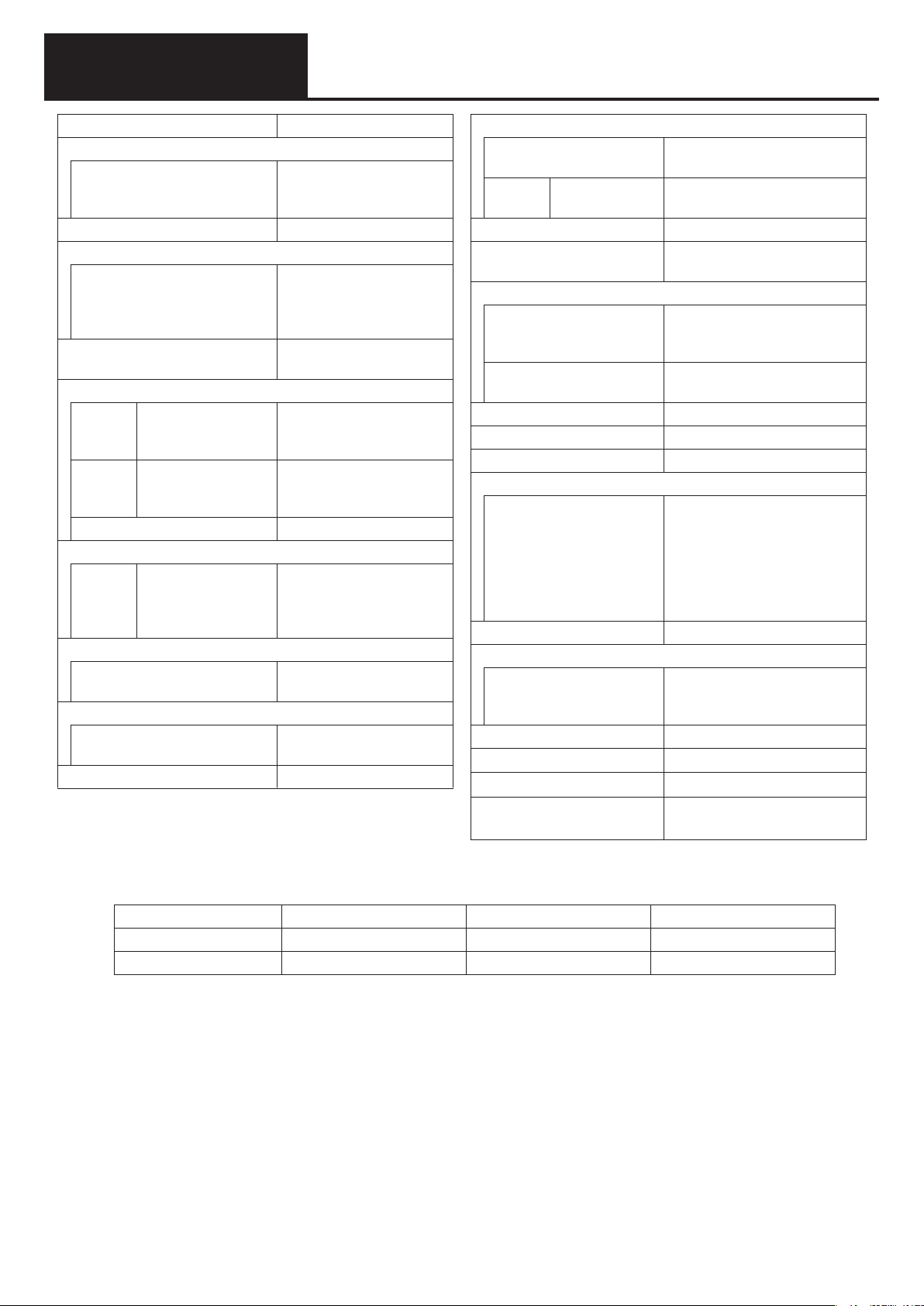
2. Specifications
Model No. U-30GE3E5
External dimensions (mm)
Height
Width
Depth
Weight (kg) 880
Performance (kW)
Cooling capacity
Heating capacity (Standard)
Heating capacity (low temp.)
Hot Water (Cooling mode)
Generate electricity power source
Electrical rating
Running amperes (A)
Cooling
Heating
Starting amperes (A) 30
Gas Type
Gas Band
Gas consumption (kW)
Compressor
Cooling oil (L) (type)
Crankcase heater (W)
Paint color (Munsell code) Silky Shade (1Y8.5/0.5)
Power input (kW)
Power factor (%)
Running amperes (A)
Power input (kW)
Power factor (%)
P
H
L
E
Cooling
Heating (Standard)
46.0 (@65°C outlet)
2,255
2,026
1,000 (+80)
85.0
95.0
90.0
(Note 7)
220 to 240 V, 50 Hz,
Single-phase
8.39
1.80
93
8.09
1.75
94
Propane gas (G31)
Natural gas (G20)
Natural gas (G25)
Natural gas (G20)
84.1
75.3
5.0 (HP-9)
30
Engine
Displacement (L)
Rated output (kW)
Oil
Starter motor 12 V DC, 2.0 kW
Starter type
Engine cooling water
Quantity (L)
Concentration, Freezing
temperature
Cooling water pump rated
output (kW)
Refrigerant type, Quantity (kg) HFC [R410A] , 11.5
Air intakes Front and Rear side
Air outlet To p
Piping
Refrigerant gas (mm)
Refrigerant liquid (mm)
Exhaust drain (mm)
Hot water supply in/out
Operating noise level dB(A) 84/65 (PWL/SPL)
Ventilation System
Air flow rate (m
Rated output (kW)
Drain heater (W) 40
Quantity (L)
Fuel gas
Type
Type
3
/min)
AC/DC conversion type DC
ø25 .Rubber hose (length: 350)
2.488
18.8
Panasonic Genuine
46
starter
27
50 V/V%, –35°C
0.16
ø31.75(brazed)
(ø38.1) (Note 4)
ø19.05(brazed)
(ø22.22) (Note 4)
R3/4 (Bolt, thread)
Rp3/4 (Nut, thread)
Propeller fans (x2)
460
0.70×2
SEER 1.91
SCOP 1.33
Design Pressure
(HP/LP) (MPa)
4.15/2.5
Notes
1. Cooling and heating capacities in the tables are determined under the test conditions of JIS B 8627.
Operating condition Cooling Heating (standard) Heating (low temp.)
Indoor air intake temp. 27°CDB/19°CWB 20°CDB 20°CDB/15°CWB or less
Outdoor air intake temp. 35°CDB 7°CDB/6°CWB 2°CDB/1°CWB
• Effective heating requires that the outdoor air intake temperature be at least –20°CDB or –21°CWB.
2. Gas consumption is the total (high) calorific value standard.
3. Outdoor unit operating sound is measured 1 meter from the front and 1.5 meters above the floor (in an
anechoic environment). Actual installations may have larger values due to ambient noise and reflections.
4. Values in parentheses ( ) for refrigerant gas and liquid types are those when the maximum piping length
exceeds 90 meters (equivalent length). (Reducers are available locally.)
5. Specifications are subject to change without notice.
6. Hot water heating capacity is applicable during cooling operation as in Note 1.
7. The maximum water temperature that can be obtained is 65°C. Water heating performance and temperature
vary with the air conditioning load.
Because the hot water heating system uses waste heat from the engine, which runs the air conditioning,
its ability to heat water is not guaranteed.
B-7
Page 14

Outdoor Unit
2. Specifications
Model No. U-16GF3E5
External dimensions (mm)
Height
Width
Depth
Weight (kg) 775
Performance (kW)
Cooling capacity
Heating capacity (Standard)
Heating capacity (low temp.)
Hot Water (Cooling mode)
Generate electricity power source
Electrical rating
Running amperes (A)
Cooling
Heating
Starting amperes (A) 30
Gas Type
Gas Band
Gas consumption (kW)
Compressor
Cooling oil (L) (type)
Crankcase heater (W)
Paint color (Munsell code) Silky Shade (1Y8.5/0.5)
Power input (kW)
Power factor (%)
Running amperes (A)
Power input (kW)
Power factor (%)
P
H
L
E
Cooling
Heating (Standard)
23.6 (@65°C outlet)
2,255
1,650
1,000 (+80)
45.0
50.0
53.0
(Note 7)
220 to 240 V, 50 Hz,
Single-phase
5.35
1.17
95
2.71
0.56
90
Propane gas (G31)
Natural gas (G20)
Natural gas (G25)
Natural gas (G20)
45.8
42.2
4.4 (HP-9)
30
Engine
Displacement (L)
Rated output (kW)
Oil
Starter motor 12 V DC, 2.0 kW
Starter type
Engine cooling water
Quantity (L)
Concentration, Freezing
temperature
Cooling water pump rated
output (kW)
Refrigerant type, Quantity (kg) HFC [R410A] , 11.5
Air intakes Front and Rear side
Air outlet To p
Piping
Refrigerant discharge (mm)
Refrigerant gas (mm)
Refrigerant liquid (mm)
Exhaust drain (mm)
Hot water supply in/out
Operating noise level dB(A) 80/58 (PWL/SPL)
Ventilation System
Air flow rate (m
Rated output (kW)
Drain heater (W) 40
Quantity (L)
Fuel gas
Type
Type
3
/min)
AC/DC conversion type
ø25 .Rubber hose (length: 350)
2.488
10.0
Panasonic Genuine
40
DC starter
21
50 V/V%, –35°C
0.16
ø22.22(brazed)
(ø25.4) (Note 4)
ø28.58(brazed)
(ø31.75) (Note 4)
ø19.05(brazed)
(ø22.22) (Note 4)
R3/4 (Bolt, thread)
Rp3/4 (Nut, thread)
Propeller fans (x2)
370
0.70×2
SEER 1.67
SCOP 1.31
Design Pressure
(HP/LP) (MPa)
4.15/2.5
Notes
1. Cooling and heating capacities in the tables are determined under the test conditions of JIS B 8627.
Operating condition Cooling Heating (standard) Heating (low temp.)
Indoor air intake temp. 27°CDB/19°CWB 20°CDB 20°CDB/15°CWB or less
Outdoor air intake temp. 35°CDB 7°CDB/6°CWB 2°CDB/1°CWB
• Effective heating requires that the outdoor air intake temperature be at least –20°CDB or –21°CWB.
2. Gas consumption is the total (high) calorific value standard.
3. Outdoor unit operating sound is measured 1 meter from the front and 1.5 meters above the floor (in an
anechoic environment). Actual installations may have larger values due to ambient noise and reflections.
4. Values in parentheses ( ) for refrigerant gas and liquid types are those when the maximum piping length
exceeds 90 meters (equivalent length). (Reducers are available locally.)
5. Specifications are subject to change without notice.
6. Hot water heating capacity is applicable during cooling operation as in Note 1.
7. The maximum water temperature that can be obtained is 65°C. Water heating performance and temperature
vary with the air conditioning load.
Because the hot water heating system uses waste heat from the engine, which runs the air conditioning,
its ability to heat water is not guaranteed.
B-8
Page 15
Outdoor Unit
2. Specifications
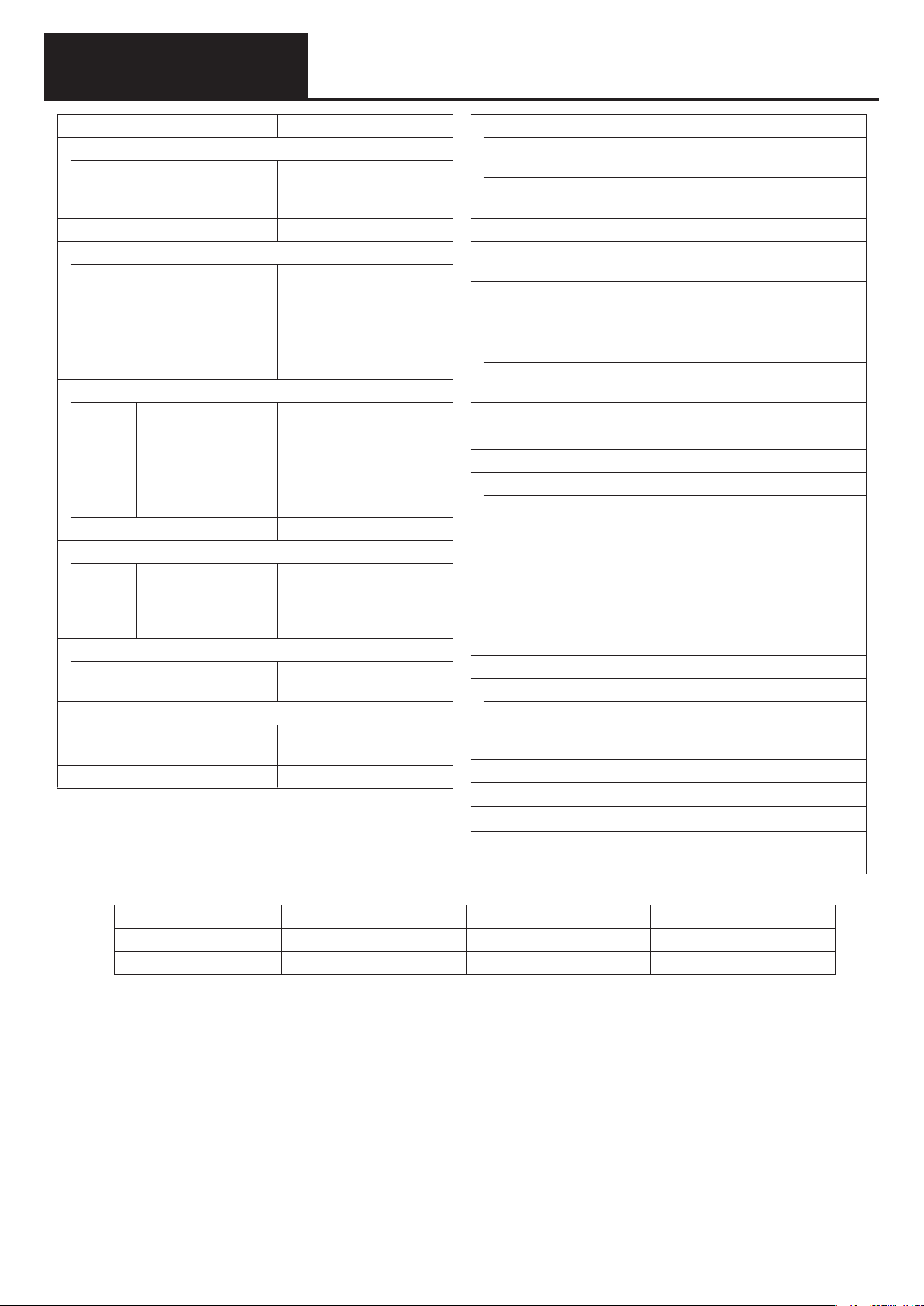
Model No. U-20GF3E5
External dimensions (mm)
Height
Width
Depth
Weight (kg) 775
Performance (kW)
Cooling capacity
Heating capacity (Standard)
Heating capacity (low temp.)
Hot Water (Cooling mode)
Generate electricity power source
Electrical rating
Running amperes (A)
Cooling
Heating
Starting amperes (A) 30
Gas Type
Gas Band
Gas consumption (kW)
Compressor
Cooling oil (L) (type)
Crankcase heater (W)
Paint color (Munsell code) Silky Shade (1Y8.5/0.5)
Power input (kW)
Power factor (%)
Running amperes (A)
Power input (kW)
Power factor (%)
P
H
L
E
Cooling
Heating (Standard)
27.1 (@65°C outlet)
2,255
1,650
1,000 (+80)
56.0
63.0
67.0
(Note 7)
220 to 240 V, 50 Hz,
Single-phase
6.45
1.40
94
4.79
1.05
95
Propane gas (G31)
Natural gas (G20)
Natural gas (G25)
Natural gas (G20)
54.8
51.1
4.4 (HP-9)
30
Engine
Displacement (L)
Rated output (kW)
Oil
Starter motor 12 V DC, 2.0 kW
Starter type
Engine cooling water
Quantity (L)
Concentration, Freezing
temperature
Cooling water pump rated
output (kW)
Refrigerant type, Quantity (kg) HFC [R410A] , 11.5
Air intakes Front and Rear side
Air outlet To p
Piping
Refrigerant discharge (mm)
Refrigerant gas (mm)
Refrigerant liquid (mm)
Exhaust drain (mm)
Hot water supply in/out
Operating noise level dB(A) 81/59 (PWL/SPL)
Ventilation System
Air flow rate (m
Rated output (kW)
Drain heater (W) 40
Quantity (L)
Fuel gas
Type
Type
3
/min)
Panasonic Genuine
AC/DC conversion type
50 V/V%, –35°C
ø25.4(brazed)
(ø28.58) (Note 4)
ø28.58(brazed)
(ø31.75) (Note 4)
ø19.05(brazed)
(ø22.22) (Note 4)
R3/4 (Bolt, thread)
ø25 .Rubber hose (length: 350)
Rp3/4 (Nut, thread)
Propeller fans (x2)
SEER 1.72
SCOP 1.32
Design Pressure
Notes
(HP/LP) (MPa)
1. Cooling and heating capacities in the tables are determined under the test conditions of JIS B 8627.
Operating condition Cooling Heating (standard) Heating (low temp.)
Indoor air intake temp. 27°CDB/19°CWB 20°CDB 20°CDB/15°CWB or less
Outdoor air intake temp. 35°CDB 7°CDB/6°CWB 2°CDB/1°CWB
2.488
12.4
40
DC starter
21
0.16
400
0.70×2
4.15/2.5
• Effective heating requires that the outdoor air intake temperature be at least –20°CDB or –21°CWB.
2. Gas consumption is the total (high) calorific value standard.
3. Outdoor unit operating sound is measured 1 meter from the front and 1.5 meters above the floor (in an
anechoic environment). Actual installations may have larger values due to ambient noise and reflections.
4. Values in parentheses ( ) for refrigerant gas and liquid types are those when the maximum piping length
exceeds 90 meters (equivalent length). (Reducers are available locally.)
5. Specifications are subject to change without notice.
6. Hot water heating capacity is applicable during cooling operation as in Note 1.
7. The maximum water temperature that can be obtained is 65°C. Water heating performance and temperature
vary with the air conditioning load.
Because the hot water heating system uses waste heat from the engine, which runs the air conditioning,
its ability to heat water is not guaranteed.
B-9
Page 16
Outdoor Unit
2. Specifications
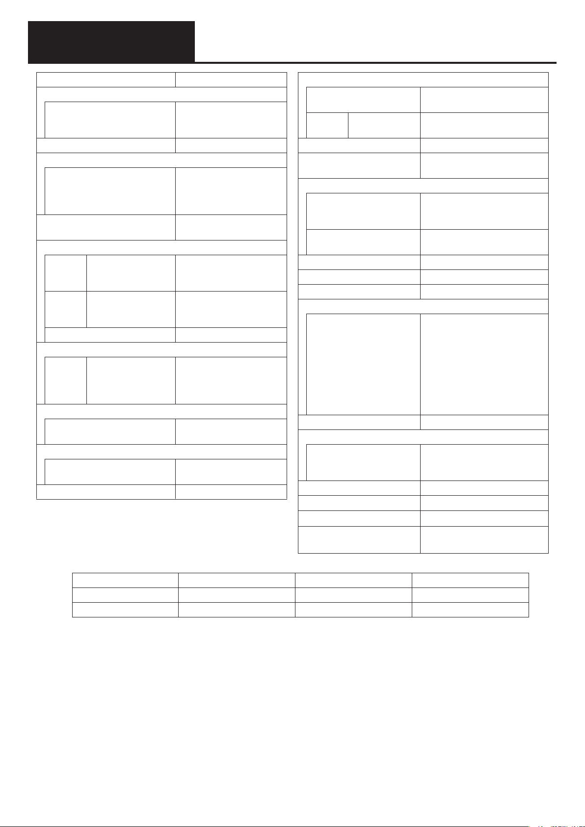
Model No. U-25GF3E5
External dimensions (mm)
Height
Width
Depth
Weight (kg) 880
Performance (kW)
Cooling capacity
Heating capacity (Standard)
Heating capacity (low temp.)
Hot Water (Cooling mode)
Generate electricity power source
Electrical rating
Running amperes (A)
Cooling
Heating
Starting amperes (A) 30
Gas Type
Gas Band
Gas consumption (kW)
Compressor
Cooling oil (L) (type)
Crankcase heater (W)
Paint color (Munsell code) Silky Shade (1Y8.5/0.5)
Power input (kW)
Power factor (%)
Running amperes (A)
Power input (kW)
Power factor (%)
P
H
L
E
Cooling
Heating (Standard)
40.5 (@65°C outlet)
2,255
2,026
1,000 (+80)
71.0
80.0
78.0
(Note 7)
220 to 240 V, 50 Hz,
Single-phase
8.39
1.80
93
4.16
0.91
95
Propane gas (G31)
Natural gas (G20)
Natural gas (G25)
Natural gas (G20)
73.7
68.6
5.5 (HP-9)
30
Engine
Displacement (L)
Rated output (kW)
Oil
Starter motor 12 V DC, 2.0 kW
Starter type
Engine cooling water
Quantity (L)
Concentration, Freezing
temperature
Cooling water pump rated
output (kW)
Refrigerant type, Quantity (kg) HFC [R410A] , 11.5
Air intakes Front and Rear side
Air outlet To p
Piping
Refrigerant discharge (mm)
Refrigerant gas (mm)
Refrigerant liquid (mm)
Exhaust drain (mm)
Hot water supply in/out
Operating noise level dB(A) 84/62 (PWL/SPL)
Ventilation System
Air flow rate (m
Rated output (kW)
Drain heater (W) 40
Quantity (L)
Fuel gas
Type
Type
3
/min)
Panasonic Genuine
AC/DC conversion type
50 V/V%, –35°C
ø25.4(brazed)
(ø28.58) (Note 4)
ø28.58(brazed)
(ø31.75) (Note 4)
ø19.05(brazed)
(ø22.22) (Note 4)
R3/4 (Bolt, thread)
ø25 .Rubber hose (length: 350)
Rp3/4 (Nut, thread)
Propeller fans (x2)
SEER 1.80
SCOP 1.39
Design Pressure
Notes
(HP/LP) (MPa)
1. Cooling and heating capacities in the tables are determined under the test conditions of JIS B 8627.
Operating condition Cooling Heating (standard) Heating (low temp.)
Indoor air intake temp. 27°CDB/19°CWB 20°CDB 20°CDB/15°CWB or less
Outdoor air intake temp. 35°CDB 7°CDB/6°CWB 2°CDB/1°CWB
2.488
15.7
46
DC starter
27
0.16
460
0.70×2
4.15/2.5
• Effective heating requires that the outdoor air intake temperature be at least –20°CDB or –21°CWB.
2. Gas consumption is the total (high) calorific value standard.
3. Outdoor unit operating sound is measured 1 meter from the front and 1.5 meters above the floor (in an
anechoic environment). Actual installations may have larger values due to ambient noise and reflections.
4. Values in parentheses ( ) for refrigerant gas and liquid types are those when the maximum piping length
exceeds 90 meters (equivalent length). (Reducers are available locally.)
5. Specifications are subject to change without notice.
6. Hot water heating capacity is applicable during cooling operation as in Note 1.
7. The maximum water temperature that can be obtained is 65°C. Water heating performance and temperature
vary with the air conditioning load.
Because the hot water heating system uses waste heat from the engine, which runs the air conditioning,
its ability to heat water is not guaranteed.
B-10
Page 17
Outdoor Unit
p
g
p
g
p
y
13
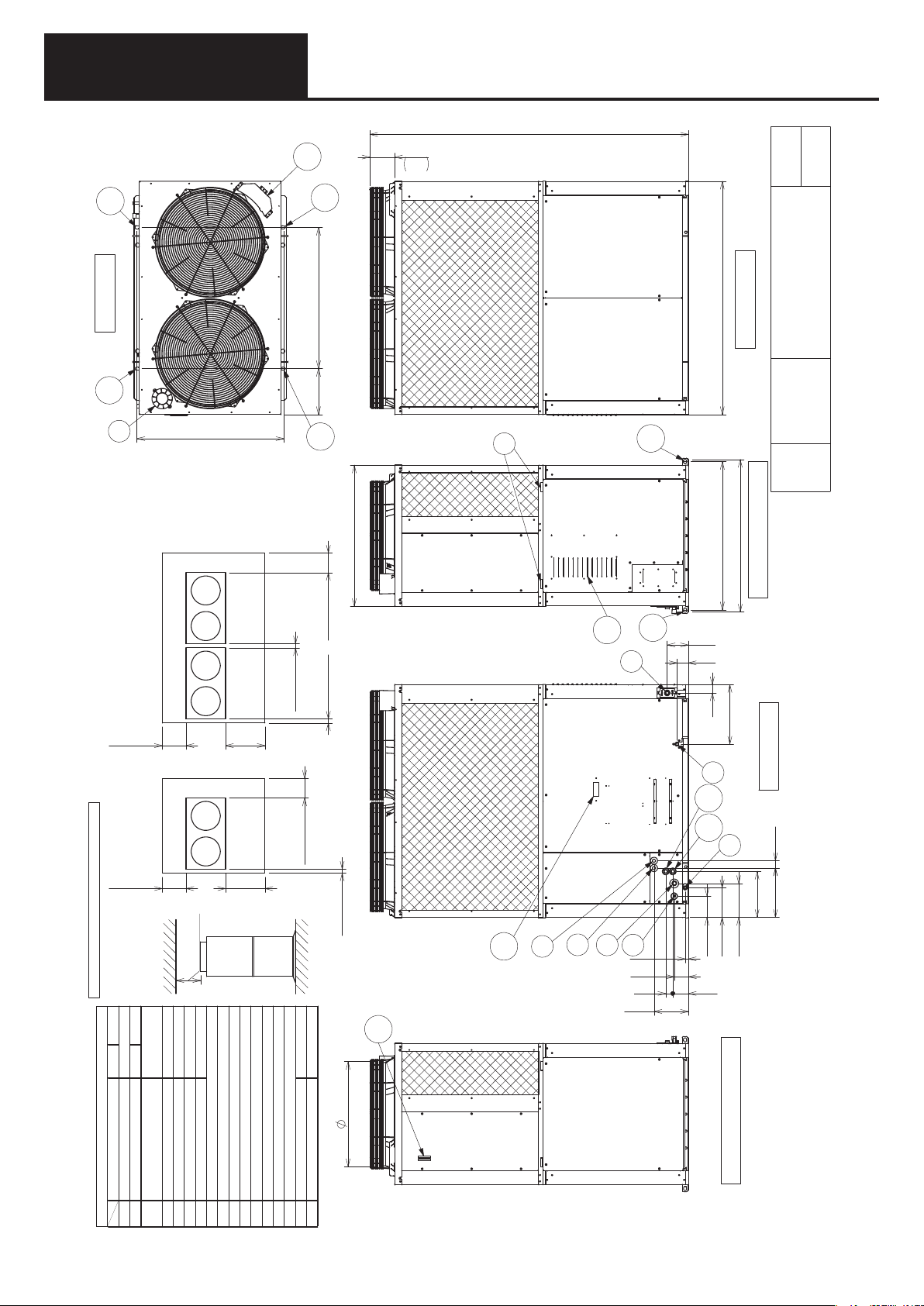
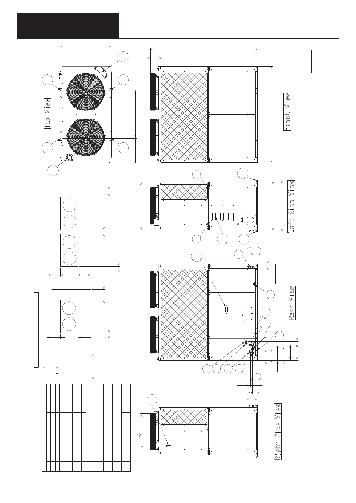
3. External Dimensions
2255(External)
176
Scale
Free
11
Top View
11
9
installation>
<Multi-unit series
550
(Units:mm)
(refrigerant tubing)
Rear View
At least
(anchor pitch)
1040(max)
1024(min)
Front ViewFront View
950
At least
11
1000
(anchor pitch)
Front View
1650(External)
drawing
External dimensions
325
U-16GE3E5
11
8
10
U-20GE3E5
Model
Name
1050
(frame width)1080
1000(External)
350
At least
14
10
6
100
100
At least
At least
(suspension holes)
Left Side View
150
80
60
422
3
Rear View
17
16
51353
7
326
153
243
213
(refrigerant tubing)
Rear View
installation>
<Single-unit
550
At least
2000
At least
350
At least
950
At least
100
At least
1
12
5
4
2
22
100
Service Clearances for Installation
Wk0.65Wk0.54epyT
Size (mm)
φ28
φ28
φ20
φ28.58
② Liquid refrigeran t pipe φ12.7 φ15.88
① Gas ref rigerant pipe
R3/4
(acce ssory)
HOSE OD:φ25
enin
ension holes 4-φ20×3 0
Sus
Engine e xhaust ou tlet
Rain and co ndensation o utlet
Anchor holes 4 -22×3 0
⑦ Con densation drain o
⑥ Fuel gas port
⑤ Inter-u nit cable port
④ Electrical powe r supply port
③ Exhaust gas drain port
⑧⑨⑩⑪⑫⑬⑭⑮⑯ Hot water inlet
Rp3/4
Rp3/4
la
mented dis
Se
Air intake
Coolant le bel
Coolant in take(top)
⑰ Hot water outlet
15
744
50
243
111
Right Side View
B-11
Page 18
Outdoor Unit
Service Clearances for Installation
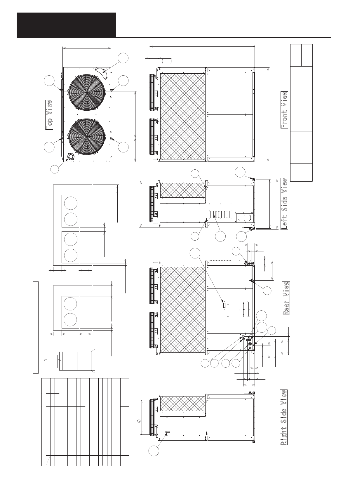
3. External Dimensions
11
ew
Vi
op
T
11
9
Rear View
(refrigerant tubing)
installation>
<Multi-unit series
(anchor pitch)
1040(max)
1024(min)
13
176
2255(External)
Free
Scale
11
w
e
i
1000
(anchor pitch)
11
513
8
350
At least
100
At least
Front View
1000
(External)
8
14
12
10
10
6
2026(External)
1050
(suspension holes)
150
80
nt V
o
r
External dimensions
F
View
e
ft Sid
e
1080(frame width)
L
drawing
U-30GE3E5
U-25GE3E5
Model
Name
550
(Units:mm)
installation>
<Single-unit
Wk0.58Wk0.17epyT
Size ( mm)
At least
(refrigerant tubing)
Rear View
550
At least
2000
At least
(accesso ry)
HOSE OD:φ2 5
③ Exhaust gas drain port
② Liquid refrige rant pipe φ15.88 φ19 .05
① Gas refrigerant pipe φ28.5 8 φ31.75
φ28
④ Electrical power supply port
950
Front View
950
φ28
φ20
R3/4
Engine exhau st outle t
Rain and condensation outle t
⑧⑨⑩⑪⑫⑬⑭⑮⑯ Hot water inlet
⑦ Condensation drain opening
⑥ Fuel gas port
⑤ Inter-unit c able port
At least
100
At least
350
At least
At least
100
At least
5
4
Rp3/4
Rp3/4
744
play
Segmente d dis
Anchor h oles 4-2 2×30
Air intake
Suspen sion h oles 4-φ20×30
Coolan t lebel
Coolan t intake(top)
⑰ Hot water ou tlet
15
2
1
22
100
50
243
60
422
w
3
e
i
V
r
a
e
R
17
16
153
213
111
51
7
353
326
243
w
e
i
V
e
d
Si
t
h
g
i
R
B-12
Page 19

Outdoor Unit
12
Top View
14
1000
12
(anchor pitch)
3. External Dimensions
2255(External)
176
Free
Scale
Front View
1650(External)
External dimensions
drawing
12
10
Rear View
(refrigerant tubing)
installation>
<Multi-unit series
550
At least
(Units:mm)
(refrigerant tubing)
Rear View
<Single-unit
installation>
550
At least
2000
Service Clearances for Installation
Wk0.65Wk0.54epyT
Size (mm)
φ19.05
φ28.58
At least
φ28
φ28
R3/4
(accessory)
HOSE OD:φ25
(anchor pitch)
1040(max)
1024(min)
Front View
950
At least
Front View
950
At least
φ20
325
12
1000(External)
350
At least
100
At least
100
At least
9
15
11
1050
(frame width)1080
(suspension holes)
11
7
150
80
60
Left Side View
422
U-20GF3E5
U-16GF3E5
Model
Name
4
18
Rear View
350
At least
100
At least
4
Rp3/
Rp3/4
16
13
5
6
2
22
3
100
153
50
243
17
153
1
8
213
183
111
51
353
326
243
744
Right Side View
Coolant intake(top)
Segmented display
Anchor holes 4-22×30
Air intake
Suspension holes 4-φ20×30
Engine exhaust outlet
Rain and condensation o utlet
⑨⑩⑪⑫⑬⑭⑮⑯⑰ Ho t water inlet
⑧ Con densation drain opening
⑦ Fuel gas port
⑥ Inter-unit cable port
⑤ Electrical power supply port
④ Exhaust gas drain port
③ Liquid refrigerant pipe
② Discharge Gas refrigerant pipe φ22.22 φ25.4
① Suction Gas refrigerant pipe
Coolant lebel
⑱ Ho t water outlet
B-13
Page 20
Outdoor Unit
Service Clearances for Installation
3. External Dimensions
12
iew
p V
o
T
12
10
(refrigerant tubing)
Rear View
installation>
<Multi-unit series
550
(Units:mm)
Rear View
(refrigerant tubing)
<Single-unit
installation>
550
(anchor pitch)
1040(max)
1024(min)
14
176
2255(External)
Free
Scale
12
iew
V
t
n
Fro
External dimensions
drawing
12
1000
(anchor pitch)
513
2026(External)
U-25GF3E5
9
350
At least
100
At least
Front View
950
At least
At least
At least
1000
(External)
9
100
13
15
11
w
Model
e
i
de V
1050
(suspension holes)
i
1080(frame width)
eft S
L
Name
11
150
7
80
60
422
w
4
e
Vi
350
At least
Front View
950
At least
At least
100
At least
18
17
1
ar
e
R
51
7
353
326
2000
At least
Size (mm)
φ28.58
① Suc tion Gas refrigerant pipe
φ28
φ25.4
φ19.05
(accesso ry)
HOSE OD:φ25
⑤ Electrical powe r supply port
④ Exhaust g as drain port
③ Liquid refrigerant pipe
② Disc harge Gas refrigerant pipe
φ28
φ20
R3/4
Engine exhau st outlet
Rain and con densation outlet
⑨⑩⑪⑫⑬⑭⑮⑯⑰ Hot water inlet
⑧ Con densation drain opening
⑦ Fue l gas port
⑥ In ter-unit cable port
5
Rp3/4
Rp3/4
les 4-2 2×30
Anchor h o
Air intake
Suspension holes 4-φ2 0×30
Coolant lebel
Coolant intake(top)
Segmented display
⑱ Hot water outlet
16
744
22
100
153
50
243
153
243
183
213
111
w
Vie
e
d
i
S
t
h
g
i
R
3
2
6
B-14
Page 21
Outdoor Unit
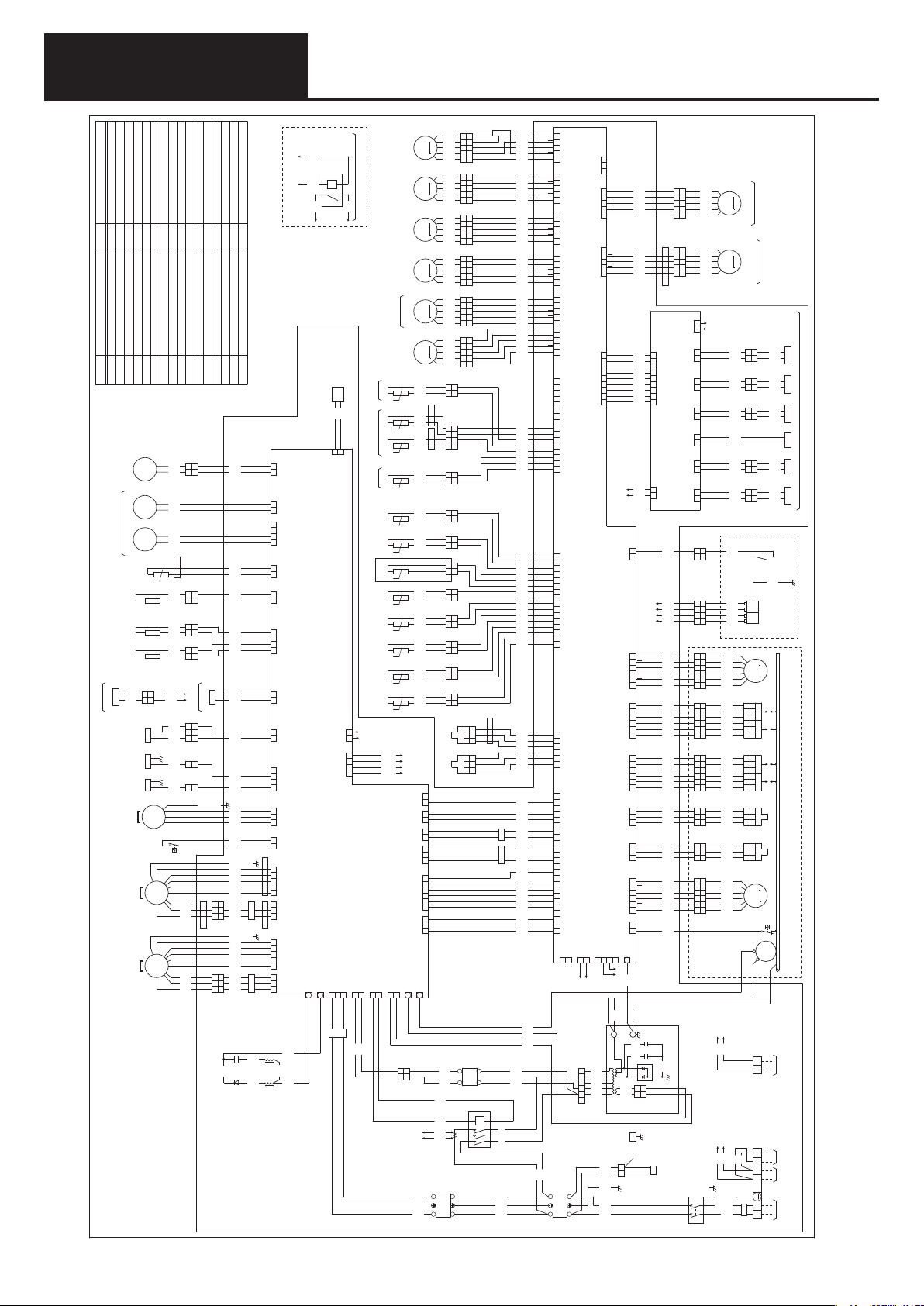
4. Wiring Diagram
NameSymbol
Discharge Valve 1-1
Discharge Valve 1-2
Discharge Valve 1-3
Discharge Valve 2
DV1-1
DV1-2
DV1-3
DV2
NameSymbol
Heat Exchanger Inlet Temperature SensorTH3
Heat Exchanger 2 Inlet Temperature SensorTH4
Compressor Inlet Temperature Sensor
Compressor Outlet Temperature Sensor
TH2
TH1
Used For 25 and 30HP Model
TH15
Crank
Case
Heater
Drain
Filter
Heater 2
Drain
Filter
Heater 1
RED
RED
DV
DV1-3
Used For
3WAY 25HP Model
Oil
Pump
Clutch
Coil 2
Clutch
Coil
Cooling
Water
Pump
Motor
Refrigerant
Fan Motor 2
Fan Motor 1
Electrical
Suction Valve 1
Suction Valve 2-1
Suction Valve 2-2
Noise Filter 1
Noise Filter 2
NF1
NF2
SV1
SV2-1
SV2-2
Catalyst Temperature SensorTH9
Hot Water Outlet Temperature SensorTH10
Cooling Water Temperature SensorTH6
Clutch Coil Temperature Sensor
Outdoor Temperature Sensor
TH7
TH8
YEL
YEL
OBV
YEL
YEL
RTV2
BLU
BLU
RTV1
GRY
°
t
BRN
BRN
WHT
WHT
WHT
WHT
YEL
YEL
1 2
1 2
)
BLK
2P-1
(
BLU
BLU
OPM
BLK
CL2
BLK
CL
PM
3 ~
High
Presure
SW
FM
3 ~
FM
3 ~
Wiring
Diagram
Circuit Breaker
Noise Filter 3
Capacitor 1
Capacitor 2
Capacitor 3C3
NF3CBC1
C2
Hot Water Inlet Temperature Sensor
Oil Level Measurement Temperature SensorTH11
Exhaust Gas Temperature Sensor
Clutch Coil Temperature Sensor 2
Ignition Coil 1 ~4IG1 ~4
TH12
TH14
TH15
1 2
1 2
)
WHT
2P-5
(
1 2
1 2
)
GRN
2P-4
(
1 2
1 2
)
WHT
2P-3
(
1 2
1 2
)
YEL
(
2P-2
20S
4-WAY Valve
Not Used
For 3WAY System
1 2 3
1 2 3
)(
BLK
3P-3
(
1
1
)
WHT
1P-2
(
1
1
)
WHT
1P-1
GRN/YEL
BLK
WHT
RED
1 2 3
1 2 3
)
WHT
BLK
3P-2
(
BLK
WHT
RED
1 2 3
1 2 3
)
BLK
3P-1
(
YEL
Diode 1D1
Reactor 1L1
BLK
BLK
RED
RED
WHT
RED
WHT
RED
WHT
BLK
RED
RED
WHT
BLU
GRY
BRN
BLK
WHT
RED
BLK
BLK
ORG
BLU
YEL
GRY
PNK
BLK
WHT
RED
ORG
BLU
YEL
GRY
PNK
BLK
WHT
RED
C1
D1
Diode 2D2
Reactor 2L2
GRN/YEL
GRN/YEL
FC FC
PNK
ORG
MAIN PCB
CN018-9PIN
MAIN PCB
CN018-7PIN
Not Used For 3WAY System
)
AC200V/0V
BLK
1 3
OBV
CN017
3P(
)
AC200V/0V
YEL
1 3
RTV2
CN027
3P(
)
RED
AC200V/0V
CN004
7P(
RTV1 EDH
)
GND
RED
SIG
1 3
TH15
CN040
3P(
)
AC200V/0V
ORG
CH
1 3
CN035
3P(
AC200V/0V
)
BLK
AC200V/0V
CN031
7P(
1 3 5 7 1 3 5 7
AUH1 AUH2
)
AC200V/0V
WHT
1 3
VRR
CN033
3P(
)
DC90V/0V
GRN
1 3
OPM
CN032
3P(
)
DC12V/0V
CL2
YEL
CN008
4P(
CL
DC12V/0V
)
RED
PM
CN023
1 2 3
3P(
)
AC200V/0V
WHT
1 4
63PHFM1 P.D.1 FM2 P.D.2
CN014
4P(
WHT
)
BLK
CN001
5P(
1 2 3 4 5 1 2 3 4
)
BLK
CN007
1 2 3
3P(
WHT
)
BLK
CN005
5P(
1 2 3 4 5
)
BLK
CN006
1 2 3
3P(
YEL
L2
WHT
WHT
L1
WHT
1
5
WHT
3
4
Used For Hot Water System
BRN
BRN
f
e
Used For
30HP Model
Suc
Used For
RED
RED
Used For
Hot Water
AC200V/0V
1
3
)
RED
HESV
CN016
3P(
Used For
)
n
BLU
1 4
m
CN015
4P(
AC OUT
GND
)
POWER PRINTED CKT BD ASSY
WHT
GND
CN041
7P(
1 3 5 7
VG01 VG02
)
BLU
AC-IN
CN002
3P(WHT)
1
2
3
AC230V/0V
FC
AC-IN2
CN013
1
AC200V/0V
BRN
52S
4P(
4
BLU
L1
CN009
L2
CN010
+
+
TH11
W System
TH12
System
TH10
TH4
3WAY Model
TH8
TH7
TH6
TH14
TH9
TH3
TH2
TH1
DC180V/0V
DC180V/0V
)
YEL
CN028
3P(
131
AC230V/0V
Expansion
Cooling Water
Liguid Valve
By-Pass
Expansion
Not Used For
3WAY and 16HP
Expansion
°
t
°
t
°
t
°
t
°
t
°
t
°
t
°
t
°
t
°
t
°
t
°
t
WHT
YEL
BLK
RED
)
WHT
STR
CN022
3P(
3
AC11V/0V
1 2
M
Valve
M
3WAY Motor Valve
M
M
Valve
M
Valve1-2
M
Valve1-1
BLK
BLK
BLK
BLK
BLK
BLK
BLK
BLK
BLK
BLK
BLK
BLK
BLK
BLK
BLK
BLK
BLK
BLK
RED
RED
BLK
BLK
i j
h
g
)
RED
1 3
63Q3
CN038
3P(
)
BLK
1 3
FBVG
CN101
3P(
)
BLK
1 3
12VC
CN025
3P(
)
WHT
DCM
CN024
1 2 3
3P(
)
WHT
CN026
6P(
OUT-MAIN
1 2 3 4 5 6
)
BLU
12VA
CN021
1 2 3
3P(
PPL
CN084
PNK
CN085
+
+
DC12V/0V
DC12V/0V
1 2
)
WHT
2P-6
(
ba
WHT
RED
BLK GRN
4
3
1 2
3 4
1 2
1 2
1 2
1 2
1 2
1 2
1 2
1 2
1 2
1 2
Refrigerant
High Pressure
Sensor
Sensor
Refrigerant
Low Pressure
BLU
BRN
GRY
RED
BLK
BLK
Noise
Filter2
NF2
GRY
BLK
YEL
RED
ORG
1 2 3 4 5
1 2 3 4 5
5P-6
YEL
GRY
GRN
WHT
BRN
1 2 3 4 5
1 2 3 4 5
5P-5
GRY
BLK
YEL
RED
ORG
1 2 3 4 5
1 2 3 4 5
5P-4
GRY
BLK
YEL
RED
ORG
1 2 3 4 5
1 2 3 4 5
5P-3
GRY
BLK
YEL
RED
ORG
1 2 3 4 5
1 2 3 4 5
5P-2
GRY
BLK
YEL
RED
ORG
1 2 3 4 5
1 2 3 4 5
5P-1
1 2
)
BLK
(
2P-16
3 4
1 2
)
BLK
4P-1
(
1 2
)
RED
(
2P-15
1 2
)
RED
(
2P-14
1 2
)
WHT
(
2P-13
1 2
)
GRY
(
2P-12
1 2
)
RED
(
2P-11
1 2
)
WHT
(
2P-10
1 2
)
BLU
2P-9
(
1 2
)
RED
2P-8
(
1 2
)
BLK
2P-7
(
3 2 1
3 2 1
3 2 1
3 2 1
Noise
Filter3
2
NF3
1
A1135
CT
2
1
BLK
B
RED
YEL
GRY
ORG
)
BLU
(
YEL
GRY
BLU
WHT
BRN
)(
BLK
(
GRY
BLK
YEL
RED
ORG
)
RED
(
GRY
BLK
YEL
RED
ORG
)
WHT
(
GRY
BLK
YEL
RED
ORG
)
GRY
BLK
WHT
(
YEL
RED
ORG
)
BLK
BLU
BLU
WHT
WHT
BLK
BLK
BLK
BLK
BRN
BRN
ORG
ORG
BLK
RED
GRY
GRY
WHT
WHT
BLU
BLU
RED
RED
BLK
BLK
BLK
BLK
ORG
)
RED
BLK
BLK
3P-5
(
BRN
RED
)
BLK
3P-4
(
PNK
WHT
RED
BLK
ORG
FC
GRY
FC
WHT
YEL
ORG
BRN
BLK
WHT
RED
BLK
WHT
RED
BLU
3
BRN
4
52S
A2
246
BLU RED
WHT
GRN
RED
)
B
A
WHT
CN072
DC12V
5P(
)
A
1 2 3 4 5
WHT
N/P
CN013
1 2 3
3P(
B
)
B
A
BLU
CN074
DC12V
5P(
)
A
1 2 3 4 5
BLK
CN071
5P(
DC12V
)
B
A
YEL
CN070
B
5P(
A
1 2 3 4 5
)
DC12V
RED
)
B
CN073
5P(
A
GRN
CN069
B
5P(
A
1 2 3 4 5
DC12V
B
A
B
)
A
WHT
DC12V
CN089
10P(
B
A
B
A
1 2 3 4 5 6 7 8 9 10
)
WHT
CN018
9P(
)
BLK
SIG
CN091
16P(
GND
SIG
GND
SIG
GND
SIG
GND
1 2 3 4 5 6 7 8 9 10 11 12 1314 15 16
SIG
GND
SIG
GND
SIG
MAIN PRINTED CKT BD ASSY
GND
SIG
)
GND
WHT
SIG
CN086
16P(
GND
SIG
GND
SIG
GND
SIG
GND
GND
SIG
PS2PS1
)
DC5V
RED
GND
CN049
6P(
SIG
DC5V
1 2 3 4 5 6
)
RED
DC12V/0V
1 3
63Q2 TH-Gr1 TH-Gr2
CN021
3P(
)
SIG
BLK
1 3
FBVG
CN043
3P(
)3P(
GND
BLK
DC12V
1 3
12VC
CN006
3P(
)
SIG
BLK
DCM
CN083
1 2 3
DC12V/0V
)
DC12V/0V
DC12V/0V
BLK
CN019
DC12V/0V
7P(
OUT-POW
DC12V/0V
DC12V
1 2 3 4 5 6 7 1 2 3 4 5 6 7 8 9 10 11 12 13 1415 16
)
GND
DC7V
BLU
12VA
CN001
DC12V
1 2 3
3P(
)
)
YEL
RED
CT1
CN063
3P(
C-M
CN020
3P(
131
3
SIG
a
b
PPL
PNK
WHT
WHT
TRM
BLCK
(TB3)
1 2 3 4 5 6
RED
WHT
Noise
Filter1
2
4
NF1
1
3
DC12V
B
A
B
A
1 2 3 4 5
B
B
A
DC12V
A
1 2 3 4 5
DC12V
OUT-RAY
1 2 3456 789
)
GRN
CN040
3P(
)
YEL
CN065
6P(
)6P(
BLK
CN011
6P(
)
WHT
CN010
6P(
)
BRN
CN016
3P(
)
WHT
CN015
3P(
)
BLK
CN066
)
RED
CN012
3P(
)
WHT
CN045
4P(
OC
1
234
SIG
y z
BLK
+
BLK
RED
YEL
BLUWHT
TRM
BLCK
WHT
RED
1 2
GRN
WHT
RED
DC12V/0V
DC12V/0V
DC12V/0V
DC12V/0V
DC12V/0V
DC12V/0V
DC12V/0V
DC12V/0V
nm
FGLP
IG3 IG4
IG1 IG2
CAM
CRA
63Q
FG
+
BLK
WHT BRN
(TB4)
TM075
1 3
B
B
A
A
1 2 3 4 5 6
1 2 3 4 5 6
1 2 3 4 5 6
1 2 3
1 2 3
B
B
A
A
1 2 3 4 5 6
1 3
BLK
-
PNK
PNK
1 2
AL
WHT
GRY
BLK
YEL
RED
ORG
YEL
GRY
BLU
WHT
BRN
WHT
GRY
PPL
BLU
PNK
YEL
RY-SIG
ORG
RED
BRN
1 2 3456 789
WHT
RED
1 4
POWER
GND
DC5V/0V
ji
hg
DC12V
DC12V
SIG
GND
DC12V
SIG
GND
DC12V
SIG
GND
DC12V
SIG
GND
DC12V
GND
SIG
DC12V
GND
SIG
DC12V
DC12V
DC12V
DC12V/0V
C2 C3
D2
1 2
)
BLK
(
2P-17
Surge
Absorber
VA
Varistor
1 2 3 4 5
1 2 3 4 5
)
WHT
5P-8
(
1 2 3 4 5
1 2 3 4 5
)
BLK
BLK
5P-7
(
1 4
OUT7
CN007
4P(BLK)
)3P(
YEL
1 4
OUT8
CN008
4P(
)
)3P(
WHT
CN010
YEL
9P(
1 31 31 31 31 3
OUT6
CN006
)
BLU
OUT5
CN005
)
BLK
OUT4
CN004
3P(
)
RED
RELAY PRINTED CKT
BD ASSY
OUT3
CN003
3P(
)
)
BLU
WHT
CN009
4P(
OUT2
CN002
3P(
YEL
YEL
1 2
1 2
WHT
YEL
BLK
RED
1 2 3 4
1 2 3 4
BLU
YEL
ORG
BRN
WHT
RED
1 2 3 4 5 6
1 2 3 4 5 6
YEL
BLK
ORG
PNK
BLK
ORG
1 2 3 4 5 6
1 2 3 4 5 6
RED
BLK
ORG
BRN
BLK
ORG
1 2 3 4 5 6
1 2 3 4 5 6
BLK
YEL
RED
1 2 3
1 2 3
BLK
BLU
RED
1 2 3
1 2 3
BLU
YEL
ORG
BRN
WHT
RED
1 2 3 4 5 6
1 2 3 4 5 6
PNK
Starter Motor
Power Supply
BRN
LOADCBLINE
R S
U V
GRY
BLK
YEL
M
RED
ORG
Expansion Valve 2
Used For 3WAY Model
YEL
GRY
GRN
M
WHT
BRN
fe
WHT
AC200V/0V
WHT
YEL
AC200V/0V
YEL
WHT
AC200V/0V
WHT
RED
AC200V/0V
RED
YEL
AC200V/0V
YEL
YEL
AC200V/0V
YEL
BRN
BLU
)(
RED
(
2P-18
WHT
YEL
BLK
RED
)
WHT
4P-2
(
BLU
YEL
ORG
BRN
WHT
RED
)
RED
6P-2
(
WHT
BLK
RED
WHT
BLK
RED
)
)
BLU
GRY
6P-4
(
(
3P-12
WHT
BLK
RED
WHT
BLK
RED
)
)
BLK
GRY
6P-3
(
(
3P-10
BLK
YEL
RED
)
(※)
RED
3P-7
3P-9
(
BLK
BLU
RED
)
)
GRN
WHT
3P-6
3P-8
(
(
BLU
YEL
ORG
BRN
WHT
RED
)
WHT
6P-1
f
e
BRN
BRN
z
y
YEL
YEL
YEL
GRN/YEL
LT BLU
BRN
Hot Water
3WAY Motor Valve
Used For Hot Water System
1 3
1 3
)
YEL
(
3P-15
1 2
1 2
)
YEL
(
2P-21
1 3
1 3
)
BLU
(
3P-14
1 2
1 2
)
RED
(
2P-20
1 2
1 2
)
WHT
(
2P-19
VG01 VG02
Fuel Gas Valve1,2
M
IB
3P-13
IG4
IB + G
IG3
+ G
IB
3P-11
IG2
IB + G
IG1
+ G
M
S
STR
B
TRM
(TB2)
BLCK
1 2
TRM
(TB1)
BLCK
YEL
N 1 2 3 4
FC
L
8FA25251443000
RED
RED
SV2-2
SV2-2
RED
RED
DV1-2
DV1-2
RED
RED
SV2-1
SV2-1SV1
SV1
RED
RED
DV2
DV2
RED
RED
DV1-1
DV1-1
Fuel Gas L
Pressure SW
GRN
VG01 : Inlet Side
VG02 : Governor Side
Valve
Fuel Gas
Adjustment
)
GRY
(
(Foreth Cylinder)
(Third Cylinder)
)
GRY
(
(Second Cylinder)
(First Cylinder)
Cam
Angle
Sensor
Angle
Crank
Sensor
Valve
Throttle
Engine Oil
Pressure SW
Starter
Pump
Out put
Operate
External
BRANCH
LINE
LINE
UNIT
CONTROL
POWER
SUPPLY
Used For 3WAY Model
Fuel Gas Box
: BLK
20HP
~
25 ・30HP : GRN
※16
(Engine)
B-15
Page 22
Outdoor Unit
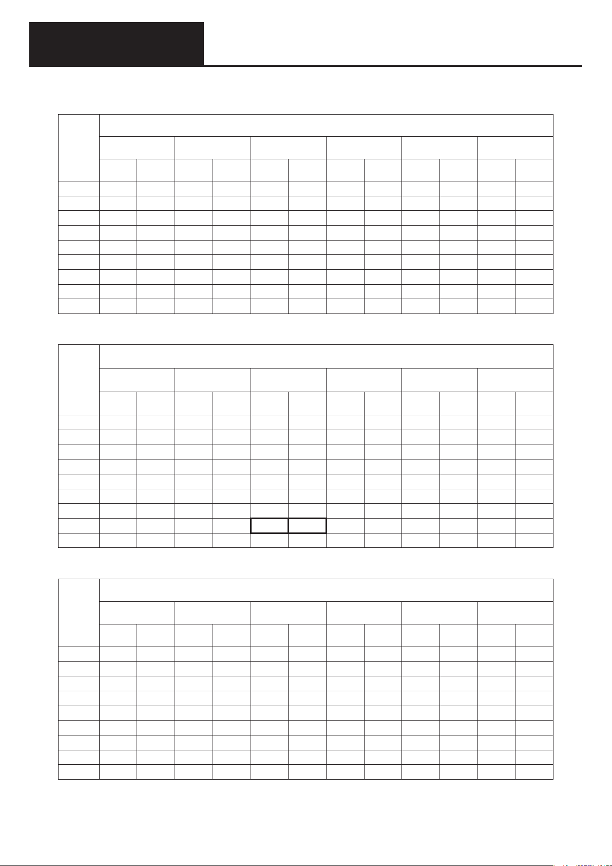
5. Performance Characteristics
U-16GE3E5,U-16GF3E5 [45.0 kW type]
1) Cooling capacity
Capacity ratio: 130% (Total capacity of indoor units: 58.5 kW)
Cooling capacity characteristics (Unit: %)
Outdoor
air
intake
temp.
(°CDB)
0 98.3 90.0 107.4 95.9 110.7 96.9 113.4 99.0 116.1 101.3 116.7 101.8
5 97.8 90.1 106.9 96.1 110.2 97.1 112.8 99.2 115.6 101.5 116.2 102.0
10 97.3 90.4 106.4 96.4 109.6 97.4 112.3 99.5 115.0 101.8 115.6 102.3
15 96.9 90.9 105.8 96.9 109.1 97.9 111.7 100.0 114.4 102.4 115.0 102.9
20 96.4 91.3 105.3 97.4 108.5 98.4 111.2 100.5 113.9 102.9 114.5 103.4
25 95.9 91.8 104.8 97.9 108.0 98.9 110.6 101.0 113.3 103.4 113.9 103.9
30 95.9 94.8 104.8 101.1 108.0 102.4 110.6 104.4 113.3 107.0 113.9 107.6
35 95.9 98.4 104.8 105.0 108.0 106.5 110.6 108.6 113.3 111.3 113.9 111.9
40 91.2 104.2 97.7 112.7 101.0 116.7 103.5 119.6 106.1 122.9 106.7 124.0
16 18 19 20 22 24
(a) (b) (a) (b) (a) (b) (a) (b) (a) (b) (a) (b)
Capacity ratio: 100% (Total capacity of indoor units: 45.0 kW)
Outdoor
air
intake
temp.
(°CDB)
0 91.0 84.5 99.4 90.1 102.5 91.0 105.0 92.9 107.5 95.2 108.1 95.6
5 90.6 84.6 98.9 90.2 102.0 91.2 104.4 93.1 107.0 95.4 107.6 95.8
10 90.1 84.9 98.5 90.5 101.5 91.5 103.9 93.4 106.5 95.6 107.1 96.1
15 89.7 85.3 98.0 91.0 101.0 92.0 103.4 93.9 105.9 96.1 106.6 96.6
20 89.2 85.8 97.5 91.4 100.5 92.4 102.9 94.3 105.4 96.6 106.0 97.1
25 88.8 86.2 97.0 91.9 100.0 92.9 102.4 94.8 104.9 97.1 105.5 97.6
30 88.8 89.0 97.0 94.9 100.0 96.1 102.4 98.1 104.9 100.5 105.5 101.1
35 88.8 92.4 97.0 98.6 100.0 100.0 102.4 102.0 104.9 104.5 105.5 105.1
40 84.5 97.8 90.4 105.8 93.6 109.5 95.9 112.3 98.2 115.4 98.9 116.5
16 18 19 20 22 24
(a) (b) (a) (b) (a) (b) (a) (b) (a) (b) (a) (b)
Indoor air intake temp. (ºCWB)
Indoor air intake temp. (ºCWB)
Cooling capacity characteristics (Unit: %)
Capacity ratio: 80% (Total capacity of indoor units: 36.0 kW) Cooling capacity characteristics (Unit: %)
Outdoor
air
intake
temp.
(°CDB)
0 72.8 57.4 79.5 61.3 82.0 61.9 83.9 63.2 86.0 64.7 86.5 65.1
5 72.4 57.5 79.2 61.4 81.6 62.1 83.5 63.3 85.6 64.8 86.1 65.2
10 72.1 57.7 78.8 61.6 81.2 62.3 83.1 63.5 85.2 65.0 85.7 65.4
15 71.7 58.0 78.4 61.9 80.8 62.6 82.7 63.9 84.7 65.3 85.2 65.7
20 71.4 58.3 78.0 62.2 80.4 62.9 82.3 64.2 84.3 65.7 84.8 66.1
25 71.0 58.6 77.6 62.5 80.0 63.2 81.9 64.5 83.9 66.0 84.4 66.4
30 71.0 60.5 77.6 64.6 80.0 65.4 81.9 66.7 83.9 68.3 84.4 68.7
35 71.0 62.8 77.6 67.1 80.0 68.0 81.9 69.4 83.9 71.1 84.4 71.5
40 67.6 66.5 72.4 72.0 74.9 74.4 76.7 76.4 78.6 78.4 79.1 79.3
16 18 19 20 22 24
(a) (b) (a) (b) (a) (b) (a) (b) (a) (b) (a) (b)
Indoor air intake temp. (ºCWB)
(a) Capacity
(b) Gas consumption
B-16
Page 23
Outdoor Unit
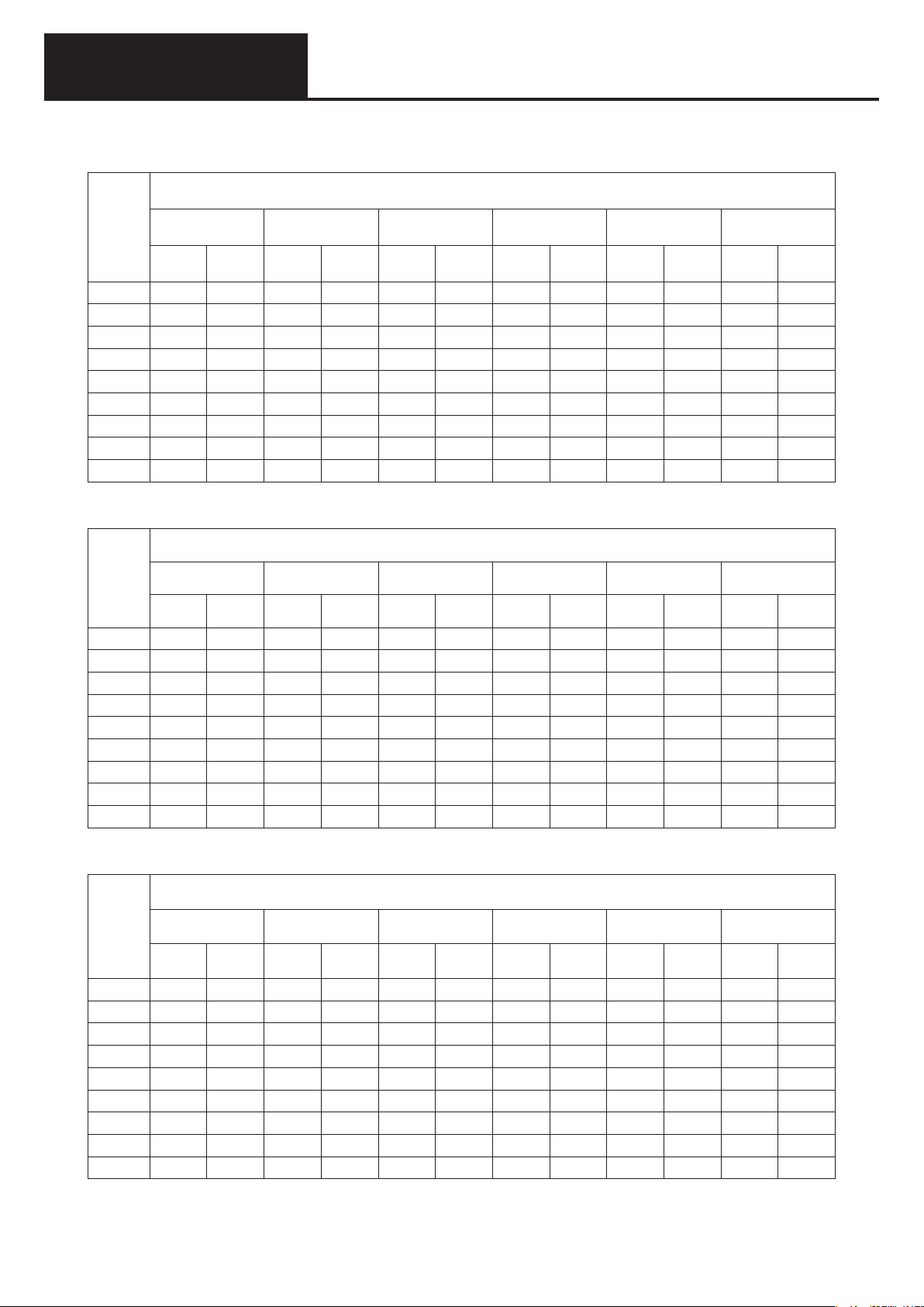
5. Performance Characteristics
[45.0 kW type]
Capacity ratio: 70% (Total capacity of indoor units: 31.5 kW) Cooling capacity characteristics (Unit: %)
Outdoor
air
intake
temp.
(°CDB)
0 63.8 45.6 69.6 48.6 71.8 49.2 73.5 50.2 75.2 51.4 75.7 51.6
5 63.4 45.7 69.3 48.7 71.4 49.3 73.1 50.3 74.9 51.5 75.4 51.8
10 63.1 45.8 68.9 48.9 71.1 49.4 72.8 50.4 74.5 51.6 75.0 51.9
15 62.8 46.0 68.6 49.1 70.7 49.7 72.4 50.7 74.1 51.9 74.6 52.2
20 62.5 46.3 68.2 49.4 70.4 49.9 72.1 50.9 73.8 52.1 74.3 52.4
25 62.2 46.5 67.9 49.6 70.0 50.2 71.7 51.2 73.4 52.4 73.9 52.7
30 62.2 48.1 67.9 51.3 70.0 51.9 71.7 52.9 73.4 54.2 73.9 54.6
35 62.2 49.9 67.9 53.2 70.0 54.0 71.7 55.1 73.4 56.4 73.9 56.8
40 59.2 52.8 63.3 57.2 65.4 59.2 67.2 60.7 68.7 62.4 69.3 63.0
16 18 19 20 22 24
(a) (b) (a) (b) (a) (b) (a) (b) (a) (b) (a) (b)
Indoor air intake temp. (ºCWB)
Capacity ratio: 60% (Total capacity of indoor units: 27.0 kW) Cooling capacity characteristics (Unit: %)
Outdoor
air
intake
temp.
(°CDB)
0 54.6 35.3 59.7 37.6 61.5 38.0 62.9 38.8 64.5 39.7 64.9 39.9
5 54.4 35.4 59.4 37.7 61.2 38.1 62.6 38.9 64.2 39.8 64.6 40.0
10 54.1 35.5 59.1 37.8 60.9 38.2 62.3 39.0 63.8 39.9 64.2 40.1
15 53.8 35.6 58.8 38.0 60.6 38.4 62.0 39.2 63.5 40.1 63.9 40.3
20 53.6 35.8 58.5 38.2 60.3 38.6 61.7 39.4 63.2 40.3 63.6 40.5
25 53.3 36.0 58.2 38.4 60.0 38.8 61.4 39.6 62.9 40.5 63.3 40.7
30 53.3 37.2 58.2 39.6 60.0 40.1 61.4 40.9 62.9 41.9 63.3 42.2
35 53.3 38.6 58.2 41.2 60.0 41.7 61.4 42.6 62.9 43.6 63.3 43.9
40 50.7 40.9 54.3 44.2 56.1 45.7 57.5 46.9 58.9 48.2 59.3 48.7
16 18 19 20 22 24
(a) (b) (a) (b) (a) (b) (a) (b) (a) (b) (a) (b)
Indoor air intake temp. (ºCWB)
Capacity ratio: 50% (Total capacity of indoor units: 22.5 kW) Cooling capacity characteristics (Unit: %)
Outdoor
air
intake
temp.
(°CDB)
0 45.5 26.9 49.7 28.6 51.3 29.0 52.5 29.6 53.8 30.3 54.1 30.4
5 45.3 26.9 49.5 28.7 51.0 29.1 52.2 29.7 53.6 30.3 53.9 30.4
10 45.1 27.0 49.2 28.8 50.8 29.2 52.0 29.7 53.3 30.4 53.6 30.5
15 44.8 27.1 49.0 28.9 50.5 29.3 51.7 29.9 53.0 30.6 53.3 30.7
20 44.6 27.3 48.7 29.1 50.3 29.5 51.5 30.0 52.8 30.7 53.1 30.8
25 44.4 27.4 48.5 29.2 50.0 29.6 51.2 30.2 52.5 30.9 52.8 31.0
30 44.4 28.3 48.5 30.2 50.0 30.6 51.2 31.2 52.5 32.0 52.8 32.2
35 44.4 29.4 48.5 34.4 50.0 31.8 51.2 32.4 52.5 33.2 52.8 33.4
40 42.3 31.1 45.3 33.6 46.8 34.9 48.0 35.7 49.2 36.8 49.5 37.0
16
(a) (b) (a) (b) (a) (b) (a) (b) (a) (b) (a) (b)
18 19 20
Indoor air intake temp. (ºCWB)
22 24
(a) Capacity
(b) Gas consumption
B-17
Page 24
Outdoor Unit
5. Performance Characteristics
[45.0 kW type]
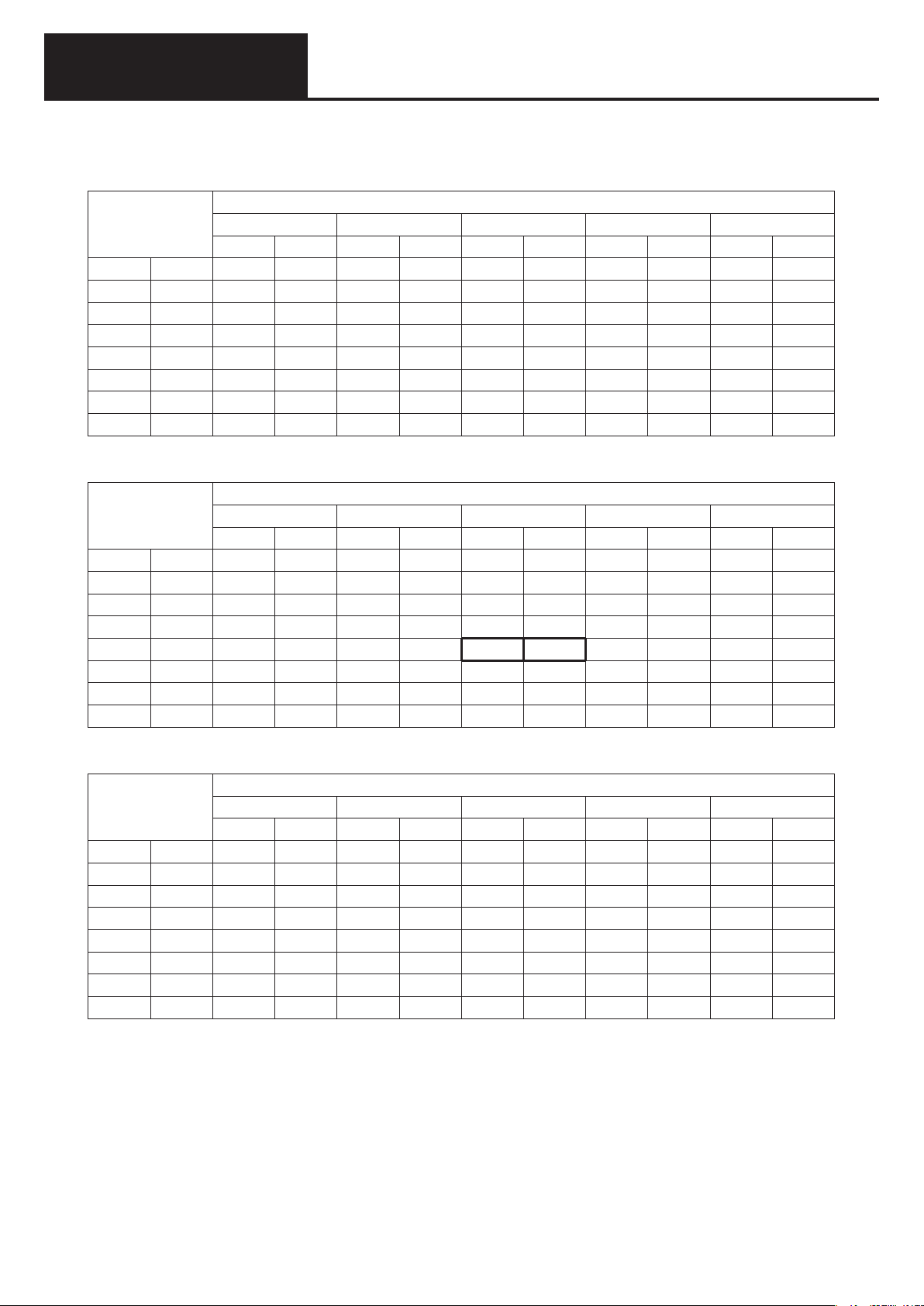
2) Heating capacity
Capacity ratio: 130% (Total capacity of indoor units: 58.5 kW) Heating capacity characteristics (Unit: %)
Outdoor air intake
temp.
(°CDB) (°CWB)
-15 -15.6 69.1 101.1 69.2 101.2 69.2 101.2 69.2 102.3 69.2 103.5
-10 -10.5 73.9 104.0 74.0 104.1 74.0 104.1 74.0 105.2 74.0 106.4
-7 -7.6 84.7 112.8 84.8 112.9 84.8 112.9 84.8 114.1 84.8 115.4
2 1.2 113.2 125.0 112.4 122.5 111.8 119.6 108.8 122.7 104.0 123.6
7 6 110.4 105.9 108.3 104.2 107.9 102.0 105.1 103.7 101.9 102.7
10 8.8 110.4 103.8 108.3 102.2 107.9 100.0 105.1 101.6 101.9 100.6
15 13.7 110.4 101.9 108.3 100.4 107.9 98.3 105.1 99.7 101.9 98.9
20 15 110.4 101.5 108.3 100.0 107.9 97.9 105.1 99.3 101.9 98.5
16 18 20 22 24
(a) (b) (a) (b) (a) (b) (a) (b) (a) (b)
Indoor air intake temp. (ºCDB)
Capacity ratio: 100% (Total capacity of indoor units: 45.0 kW) Heating capacity characteristics (Unit: %)
Outdoor air intake
temp.
(°CDB) (°CWB)
-15 -15.6 68.3 99.9 68.4 100.0 69.2 101.2 67.4 99.6 65.3 97.6
-10 -10.5 73.0 102.7 73.1 102.9 74.0 104.1 72.1 102.4 69.8 100.4
-7 -7.6 83.7 111.4 83.8 111.6 84.8 112.9 82.6 111.1 80.0 108.9
2 1.2 108.0 119.2 106.8 117.4 105.8 117.3 103.0 118.1 99.8 118.8
7 6 102.3 103.8 100.4 102.1 100.0 100.0 97.4 101.6 94.4 100.6
10 8.8 102.3 101.7 100.4 100.1 100.0 98.0 97.4 99.6 94.4 98.6
15 13.7 102.3 99.8 100.4 98.4 100.0 96.3 97.4 97.7 94.4 96.9
20 15 102.3 99.4 100.4 98.0 100.0 95.9 97.4 97.3 94.4 96.5
16 18 20 22 24
(a) (b) (a) (b) (a) (b) (a) (b) (a) (b)
Indoor air intake temp. (ºCDB)
Capacity ratio: 80% (Total capacity of indoor units: 36.0 kW) Heating capacity characteristics (Unit: %)
Outdoor air intake
temp.
(°CDB) (°CWB)
-15 -15.6 53.5 74.6 52.2 72.8 51.7 72.1 49.9 70.2 47.4 67.5
-10 -10.5 57.2 76.7 55.8 74.8 55.3 74.1 53.3 72.2 50.7 69.4
-7 -7.6 65.6 83.2 64.0 81.2 63.4 80.4 61.1 78.3 58.1 75.3
2 1.2 87.5 85.9 86.2 83.3 85.4 81.9 81.2 81.3 78.2 81.1
7 6 81.8 73.6 80.3 72.4 80.0 70.9 77.9 72.1 75.5 71.4
10 8.8 81.8 72.2 80.3 71.0 80.0 69.5 77.9 70.6 75.5 69.9
15 13.7 81.8 70.8 80.3 69.8 80.0 68.2 77.9 69.3 75.5 68.8
20 15 81.8 70.5 80.3 69.6 80.0 67.9 77.9 69.0 75.5 68.6
16 18 20 22 24
(a) (b) (a) (b) (a) (b) (a) (b) (a) (b)
Indoor air intake temp. (ºCDB)
(a) Capacity
(b) Gas consumption
B-18
Page 25
Outdoor Unit
5. Performance Characteristics
[45.0 kW type]
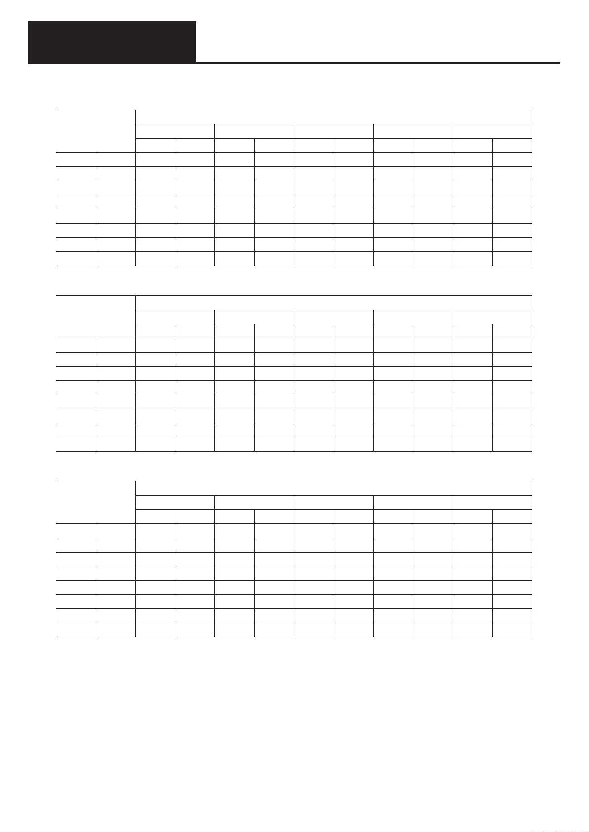
Capacity ratio: 70% (Total capacity of indoor units: 31.5 kW) Heating capacity characteristics (Unit: %)
Outdoor air intake
temp.
(°CDB) (°CWB)
-15 -15.6 46.8 61.1 45.7 59.8 45.3 59.2 43.7 57.7 41.5 55.6
-10 -10.5 50.0 62.9 48.9 61.5 48.4 60.8 46.8 59.4 44.4 57.1
-7 -7.6 57.3 68.2 56.0 66.7 55.5 66.0 53.6 64.4 50.9 62.0
2 1.2 76.0 70.2 74.9 68.3 74.3 66.9 70.6 66.6 68.0 66.5
7 6 71.6 60.3 70.3 59.3 70.0 58.1 68.2 59.0 66.1 58.4
10 8.8 71.6 59.1 70.3 58.1 70.0 56.9 68.2 57.8 66.1 57.3
15 13.7 71.6 57.8 70.3 57.2 70.0 56.0 68.2 56.7 66.1 56.2
20 15 71.6 57.5 70.3 57.0 70.0 55.8 68.2 56.5 66.1 56.0
16 18 20 22 24
(a) (b) (a) (b) (a) (b) (a) (b) (a) (b)
Indoor air intake temp. (ºCDB)
Capacity ratio: 60% (Total capacity of indoor units: 27.0 kW) Heating capacity characteristics (Unit: %)
Outdoor air intake
temp.
(°CDB) (°CWB)
-15 -15.6 40.1 48.9 39.2 47.9 38.8 47.4 37.5 46.2 35.7 44.6
-10 -10.5 42.8 50.3 41.9 49.2 41.5 48.8 40.1 47.5 38.2 45.9
-7 -7.6 49.1 54.6 48.0 53.4 47.6 52.9 45.9 51.5 43.8 49.8
2 1.2 65.6 55.8 64.6 54.3 64.1 53.3 60.9 53.0 58.7 52.9
7 6 61.4 48.0 60.2 47.2 60.0 46.2 58.4 46.9 56.6 46.5
10 8.8 61.4 47.0 60.2 46.3 60.0 45.3 58.4 46.0 56.6 45.5
15 13.7 61.4 46.0 60.2 45.4 60.0 44.6 58.4 45.2 56.6 44.7
20 15 61.4 45.8 60.2 45.2 60.0 44.5 58.4 45.0 56.6 44.5
16 18 20 22 24
(a) (b) (a) (b) (a) (b) (a) (b) (a) (b)
Indoor air intake temp. (ºCDB)
Capacity ratio: 50% (Total capacity of indoor units: 22.5 kW) Heating capacity characteristics (Unit: %)
Outdoor air intake
temp.
(°CDB) (°CWB)
-15 -15.6 33.5 38.0 32.6 37.1 32.3 36.8 31.2 35.8 29.9 34.7
-10 -10.5 35.8 39.1 34.9 38.2 34.6 37.8 33.3 36.8 31.9 35.7
-7 -7.6 41.0 42.4 40.0 41.4 39.6 41.0 38.2 39.9 36.6 38.7
2 1.2 54.7 43.6 53.8 42.3 53.4 41.6 50.7 41.3 49.0 41.3
7 6 51.2 37.4 50.2 36.8 50.0 36.0 48.7 36.6 47.2 36.2
10 8.8 51.2 36.7 50.2 36.1 50.0 35.3 48.7 35.9 47.2 35.5
15 13.7 51.2 35.9 50.2 35.5 50.0 34.7 48.7 35.3 47.2 34.9
20 15 51.2 35.7 50.2 35.4 50.0 34.6 48.7 35.2 47.2 34.8
16 18 20 22 24
(a) (b) (a) (b) (a) (b) (a) (b) (a) (b)
Indoor air intake temp. (ºCDB)
(a) Capacity
(b) Gas consumption
B-19
Page 26
Outdoor Unit
5. Performance Characteristics
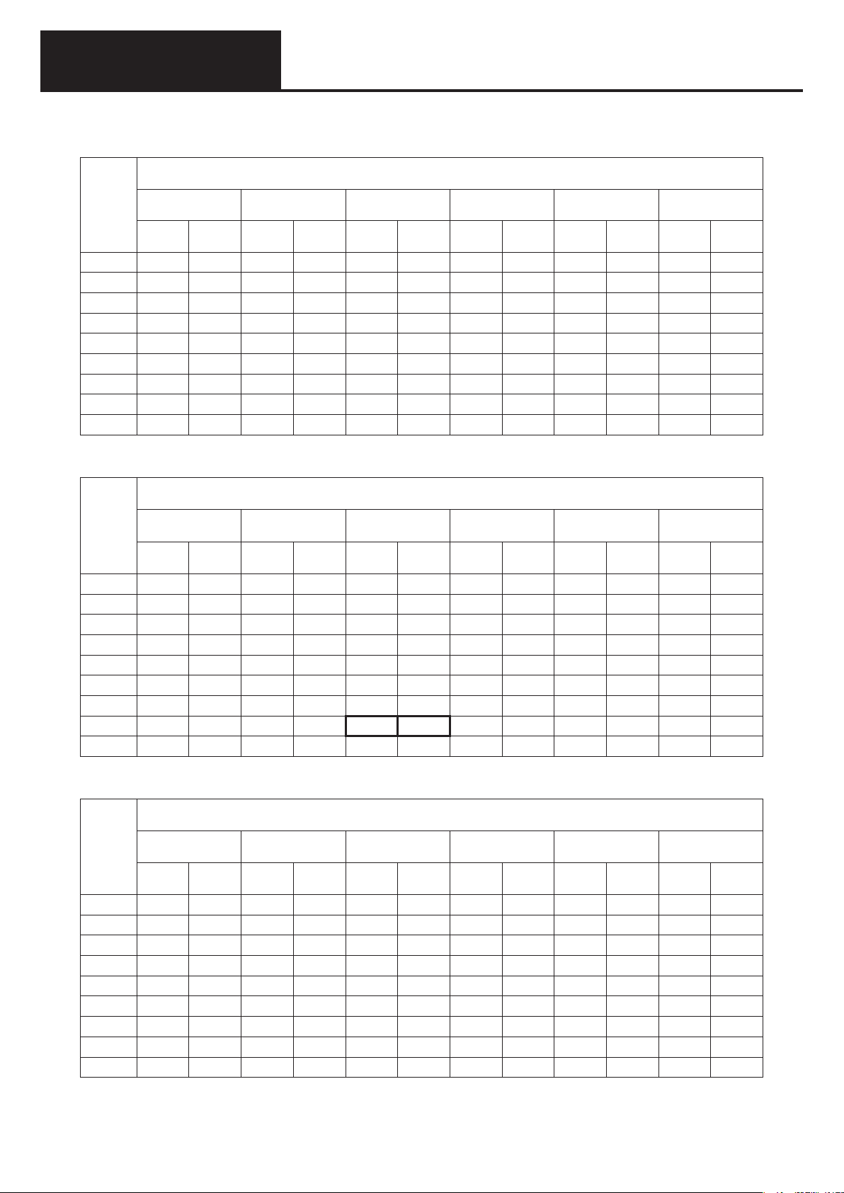
U-20GE3E5,U-20GF3E5 [56.0 kW type]
1) Cooling capacity
Capacity ratio: 130% (Total capacity of indoor units: 72.8 kW)
Cooling capacity characteristics (Unit: %)
Outdoor
air
intake
temp.
(°CDB)
0 98.3 90.0 107.4 95.9 110.7 96.9 113.4 99.0 116.1 101.3 116.7 101.8
5 97.8 90.1 106.9 96.1 110.2 97.1 112.8 99.2 115.6 101.5 116.2 102.0
10 97.3 90.4 106.4 96.4 109.6 97.4 112.3 99.5 115.0 101.8 115.6 102.3
15 96.9 90.9 105.8 96.9 109.1 97.9 111.7 100.0 114.4 102.4 115.0 102.9
20 96.4 91.3 105.3 97.4 108.5 98.4 111.2 100.5 113.9 102.9 114.5 103.4
25 95.9 91.8 104.8 97.9 108.0 98.9 110.6 101.0 113.3 103.4 113.9 103.9
30 95.9 94.8 104.8 101.1 108.0 102.4 110.7 104.7 113.3 107.0 113.9 107.6
35 95.9 98.4 104.8 105.0 108.0 106.5 110.6 108.6 113.3 111.3 113.9 111.9
40 91.2 104.2 97.7 112.7 101.0 116.7 103.5 119.7 106.1 122.8 106.7 124.0
16 18 19 20 22 24
(a) (b) (a) (b) (a) (b) (a) (b) (a) (b) (a) (b)
Capacity ratio: 100% (Total capacity of indoor units: 56.0 kW)
Outdoor
air
intake
temp.
(°CDB)
0 91.0 84.5 99.4 90.1 102.5 91.0 105.0 92.9 107.5 95.2 108.1 95.6
5 90.6 84.6 98.9 90.2 102.0 91.2 104.4 93.1 107.0 95.4 107.6 95.8
10 90.1 84.9 98.5 90.5 101.5 91.5 103.9 93.4 106.5 95.6 107.1 96.1
15 89.7 85.3 98.0 91.0 101.0 92.0 103.4 93.9 105.9 96.1 106.6 96.6
20 89.2 85.8 97.5 91.4 100.5 92.4 102.9 94.3 105.4 96.6 106.0 97.1
25 88.8 86.2 97.0 91.9 100.0 92.9 102.4 94.8 104.9 97.1 105.5 97.6
30 88.8 89.0 97.0 94.9 100.0 96.1 102.5 98.3 104.9 100.5 105.5 101.1
35 88.8 92.4 97.0 98.6 100.0 100.0 102.4 102.0 104.9 104.5 105.5 105.1
40 84.5 97.8 90.4 105.8 93.6 109.5 95.9 112.4 98.2 115.4 98.9 116.5
16 18 19 20 22 24
(a) (b) (a) (b) (a) (b) (a) (b) (a) (b) (a) (b)
Indoor air intake temp. (ºCWB)
Indoor air intake temp. (ºCWB)
Cooling capacity characteristics (Unit: %)
Capacity ratio: 80% (Total capacity of indoor units: 44.8 kW)
Outdoor
air
intake
temp.
(°CDB)
0 72.8 55.4 79.5 59.1 82.0 59.7 83.9 61.0 86.0 62.4 86.5 62.7
5 72.4 55.5 79.2 59.2 81.6 59.8 83.5 61.1 85.6 62.6 86.1 62.8
10 72.1 55.7 78.8 59.4 81.2 60.0 83.1 61.3 85.2 62.7 85.7 63.0
15 71.7 55.9 78.4 59.7 80.8 60.3 82.7 61.6 84.7 63.1 85.2 63.4
20 71.4 56.2 78.0 60.0 80.4 60.6 82.3 61.9 84.3 63.4 84.8 63.7
25 71.0 56.5 77.6 60.3 80.0 60.9 81.9 62.2 83.9 63.7 84.4 64.0
30 71.0 58.4 77.6 62.3 80.0 63.0 82.0 64.5 83.9 65.9 84.4 66.3
35 71.0 60.6 77.6 64.6 80.0 65.6 81.9 66.9 83.9 68.5 84.4 68.9
40 67.6 64.2 72.4 69.4 74.9 71.8 76.7 73.7 78.6 75.7 79.1 76.4
16 18
(a) (b) (a) (b) (a) (b) (a) (b) (a) (b) (a) (b)
Indoor air intake temp. (ºCWB)
19 20 22 24
Cooling capacity characteristics (Unit: %)
(a) Capacity
(b) Gas consumption
B-20
Page 27

Outdoor Unit
5. Performance Characteristics
[56.0 kW type]
Capacity ratio: 70% (Total capacity of indoor units: 39.2 kW)
Outdoor
air
intake
temp.
(°CDB)
0 63.8 43.2 69.6 46.1 71.8 46.6 73.5 47.5 75.2 48.7 75.7 49.0
5 63.4 43.3 69.3 46.2 71.4 46.7 73.1 47.6 74.9 48.8 75.4 49.1
10 63.1 43.4 68.9 46.3 71.1 46.9 72.8 47.8 74.5 49.0 75.0 49.3
15 62.8 43.7 68.6 46.5 70.7 47.1 72.4 48.0 74.1 49.2 74.6 49.5
20 62.5 43.9 68.2 46.8 70.4 47.4 72.1 48.3 73.8 49.5 74.3 49.8
25 62.2 44.1 67.9 47.0 70.0 47.6 71.7 48.5 73.4 49.7 73.9 50.0
30 62.2 45.6 67.9 48.6 70.0 49.2 71.7 50.3 73.4 51.4 73.9 51.7
35 62.2 47.3 67.9 50.5 70.0 51.2 71.7 52.2 73.4 53.5 73.9 53.8
40 59.2 50.1 63.3 54.1 65.4 56.1 67.1 57.6 68.7 59.1 69.3 59.7
16 18 19 20 22 24
(a) (b) (a) (b) (a) (b) (a) (b) (a) (b) (a) (b)
Indoor air intake temp. (ºCWB)
Cooling capacity characteristics (Unit: %)
Capacity ratio: 60% (Total capacity of indoor units: 33.6 kW) Cooling capacity characteristics (Unit: %)
Outdoor
air
intake
temp.
(°CDB)
16 18 19 20 22 24
(a) (b) (a) (b) (a) (b) (a) (b) (a) (b) (a) (b)
Indoor air intake temp. (ºCWB)
0 54.6 34.4 59.7 36.8 61.5 37.1 62.9 37.8 64.5 38.8 64.9 39.0
5 54.4 34.5 59.4 36.8 61.2 37.2 62.6 37.9 64.2 38.9 64.6 39.1
10 54.1 34.6 59.1 36.9 60.9 37.3 62.3 38.0 63.8 39.0 64.2 39.2
15 53.8 34.7 58.8 37.1 60.6 37.5 62.0 38.2 63.5 39.2 63.9 39.4
20 53.6 34.9 58.5 37.3 60.3 37.7 61.7 38.4 63.2 39.4 63.6 39.6
25 53.3 35.1 58.2 37.5 60.0 37.9 61.4 38.6 62.9 39.6 63.3 39.8
30 53.3 36.3 58.2 38.7 60.0 39.2 61.5 40.1 62.9 40.9 63.3 41.2
35 53.3 37.7 58.2 40.2 60.0 40.8 61.4 41.6 62.9 42.6 63.3 42.8
40 50.7 39.8 54.3 43.2 56.1 44.7 57.5 45.8 58.9 47.0 59.3 47.4
Capacity ratio: 50% (Total capacity of indoor units: 28.0 kW) Cooling capacity characteristics (Unit: %)
Outdoor
air
intake
temp.
(°CDB)
0 45.5 27.0 49.7 28.8 51.3 29.1 52.5 29.7 53.8 30.5 54.1 30.6
5 45.3 27.1 49.5 28.9 51.0 29.2 52.2 29.8 53.6 30.5 53.9 30.6
10 45.1 27.2 49.2 29.0 50.8 29.3 52.0 29.8 53.3 30.6 53.6 30.7
15 44.8 27.3 49.0 29.1 50.5 29.4 51.7 30.0 53.0 30.8 53.3 30.9
20 44.6 27.5 48.7 29.3 50.3 29.6 51.5 30.1 52.8 30.9 53.1 31.0
25 44.4 27.6 48.5 29.4 50.0 29.7 51.2 30.3 52.5 31.1 52.8 31.2
30 44.4 28.5 48.5 30.4 50.0 30.8 51.3 31.5 52.5 32.2 52.8 32.4
35 44.4 29.6 48.5 31.5 50.0 32.0 51.2 32.6 52.5 33.4 52.8 33.6
40 42.3 31.4 45.3 33.8 46.8 35.1 48.0 36.0 49.2 37.0 49.5 37.2
16 18 19 20 22 24
(a) (b) (a) (b) (a) (b) (a) (b) (a) (b) (a) (b)
Indoor air intake temp. (ºCWB)
(a) Capacity
(b) Gas consumption
B-21
Page 28
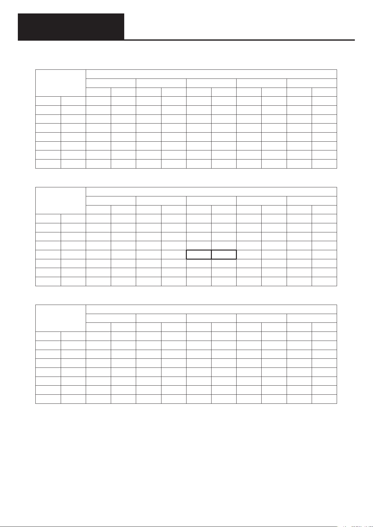
Outdoor Unit
5. Performance Characteristics
[56.0 kW type]
2) Heating capacity
Capacity ratio: 130% (Total capacity of indoor units: 72.8 kW) Heating capacity characteristics (Unit: %)
Outdoor air intake
temp.
(°CDB) (°CWB)
-15 -15.6 82.5 116.1 82.5 116.2 82.6 116.2 82.6 117.6 82.6 119.0
-10 -10.5 84.1 116.8 84.1 116.9 84.2 116.9 84.2 118.3 84.2 119.7
-7 -7.6 85.1 116.8 85.1 116.9 85.2 116.9 85.2 118.3 85.2 119.7
2 1.2 112.0 129.3 111.1 126.2 111.1 123.7 108.0 127.3 104.3 129.8
7 6 110.4 103.8 108.3 103.8 107.9 103.8 105.1 103.8 101.9 103.8
10 8.8 110.4 102.7 108.3 101.9 107.9 100.9 105.1 101.7 101.9 101.2
15 13.7 110.4 101.9 108.3 100.4 107.9 98.3 105.1 99.7 101.9 98.9
20 15 110.4 101.5 108.3 100.0 107.9 97.9 105.1 99.3 101.9 98.5
16 18 20 22 24
(a) (b) (a) (b) (a) (b) (a) (b) (a) (b)
Indoor air intake temp. (ºCDB)
Capacity ratio: 100% (Total capacity of indoor units: 56.0 kW) Heating capacity characteristics (Unit: %)
Outdoor air intake
temp.
(°CDB) (°CWB)
-15 -15.6 81.6 114.9 81.8 115.2 82.5 116.1 80.3 114.2 77.7 111.8
-10 -10.5 83.2 115.6 83.4 115.9 84.1 116.8 81.9 114.9 79.3 112.5
-7 -7.6 84.2 115.6 84.4 115.9 85.1 116.8 82.8 114.9 80.2 112.5
2 1.2 108.1 124.5 106.6 121.8 106.1 121.8 103.4 123.5 100.1 124.2
7 6 102.3 103.8 100.4 102.1 100.0 100.0 97.4 101.6 94.4 100.6
10 8.8 102.3 101.7 100.4 100.1 100.0 98.0 97.4 99.6 94.4 98.6
15 13.7 102.3 99.8 100.4 98.4 100.0 96.3 97.4 97.7 94.4 96.9
20 15 102.3 99.4 100.4 98.0 100.0 95.9 97.4 97.3 94.4 96.5
16 18 20 22 24
(a) (b) (a) (b) (a) (b) (a) (b) (a) (b)
Indoor air intake temp. (ºCDB)
Capacity ratio: 80% (Total capacity of indoor units: 44.8 kW) Heating capacity characteristics (Unit: %)
Outdoor air intake
temp.
(°CDB) (°CWB)
-15 -15.6 63.1 86.9 62.0 85.3 61.7 84.8 59.4 82.5 56.8 79.5
-10 -10.5 64.4 87.4 63.3 85.8 62.9 85.3 60.6 83.0 57.9 80.0
-7 -7.6 65.1 87.4 64.0 85.8 63.6 85.3 61.3 83.0 58.6 80.0
2 1.2 87.5 92.6 86.1 89.4 85.6 87.8 82.5 88.7 78.8 87.6
7 6 81.8 73.2 80.3 72.0 80.0 70.5 77.9 71.6 75.5 71.4
10 8.8 81.8 71.7 80.3 70.6 80.0 69.1 77.9 70.2 75.5 69.7
15 13.7 81.8 70.3 80.3 69.4 80.0 67.9 77.9 69.0 75.5 68.3
20 15 81.8 70.0 80.3 69.2 80.0 67.7 77.9 68.8 75.5 68.1
16 18 20 22 24
(a) (b) (a) (b) (a) (b) (a) (b) (a) (b)
Indoor air intake temp. (ºCDB)
(a) Capacity
(b) Gas consumption
B-22
Page 29
Outdoor Unit
5. Performance Characteristics
[56.0 kW type]
Capacity ratio: 70% (Total capacity of indoor units: 39.2 kW) Heating capacity characteristics (Unit: %)
Outdoor air intake
temp.
(°CDB) (°CWB)
-15 -15.6 55.2 74.2 54.2 72.8 54.0 72.5 52.1 70.7 49.7 68.2
-10 -10.5 56.2 74.6 55.3 73.2 55.1 72.9 53.1 71.1 50.7 68.6
-7 -7.6 56.9 74.6 55.9 73.2 55.7 72.9 53.7 71.1 51.3 68.6
2 1.2 76.1 74.4 75.0 72.2 74.4 70.7 71.8 71.5 68.6 70.6
7 6 71.6 58.9 70.3 57.9 70.0 56.7 68.2 57.6 66.1 57.0
10 8.8 71.6 57.7 70.3 56.8 70.0 55.6 68.2 56.5 66.1 55.9
15 13.7 71.6 56.6 70.3 55.7 70.0 54.5 68.2 55.4 66.1 55.0
20 15 71.6 56.4 70.3 55.5 70.0 54.3 68.2 55.2 66.1 54.8
16 18 20 22 24
(a) (b) (a) (b) (a) (b) (a) (b) (a) (b)
Indoor air intake temp. (ºCDB)
Capacity ratio: 60% (Total capacity of indoor units: 33.6 kW) Heating capacity characteristics (Unit: %)
Outdoor air intake
temp.
(°CDB) (°CWB)
-15 -15.6 47.3 60.5 46.4 59.4 46.2 59.1 44.5 57.4 42.7 55.5
-10 -10.5 48.2 60.9 47.4 59.7 47.2 59.4 45.4 57.7 43.5 55.8
-7 -7.6 48.8 60.9 47.9 59.7 47.7 59.4 45.9 57.7 44.0 55.8
2 1.2 65.5 58.8 64.5 57.0 64.2 56.0 61.8 56.4 59.2 55.8
7 6 61.4 47.5 60.2 46.7 60.0 45.8 58.4 46.5 56.6 46.1
10 8.8 61.4 46.6 60.2 45.9 60.0 44.8 58.4 45.6 56.6 45.1
15 13.7 61.4 45.7 60.2 45.0 60.0 44.2 58.4 44.6 56.6 44.3
20 15 61.4 45.5 60.2 44.8 60.0 44.1 58.4 44.4 56.6 44.1
16 18 20 22 24
(a) (b) (a) (b) (a) (b) (a) (b) (a) (b)
Indoor air intake temp. (ºCDB)
Capacity ratio: 50% (Total capacity of indoor units: 28.0 kW) Heating capacity characteristics (Unit: %)
Outdoor air intake
temp.
(°CDB) (°CWB)
-15 -15.6 39.4 47.6 38.7 46.7 38.6 46.5 37.1 45.2 35.6 43.6
-10 -10.5 40.1 47.9 39.4 47.0 39.3 46.8 37.9 45.5 36.3 43.9
-7 -7.6 40.6 47.9 39.9 47.0 39.8 46.8 38.3 45.5 36.7 43.9
2 1.2 54.7 46.9 53.9 45.4 53.5 44.5 51.5 44.8 49.3 44.3
7 6 51.2 38.4 50.2 37.7 50.0 37.0 48.7 37.6 47.2 37.2
10 8.8 51.2 37.6 50.2 37.0 50.0 36.2 48.7 36.8 47.2 36.5
15 13.7 51.2 37.0 50.2 36.4 50.0 35.6 48.7 36.2 47.2 35.7
20 15 51.2 36.9 50.2 36.3 50.0 35.5 48.7 36.1 47.2 35.5
16 18 20 22 24
(a) (b) (a) (b) (a) (b) (a) (b) (a) (b)
Indoor air intake temp. (ºCDB)
(a) Capacity
(b) Gas consumption
B-23
Page 30
Outdoor Unit
5. Performance Characteristics
U-25GE3E5,U-25GF3E5 [71.0 kW type]
1) Cooling capacity
Capacity ratio: 130% (Total capacity of indoor units: 92.3 kW)
Cooling capacity characteristics (Unit: %)
Outdoor
air
intake
temp.
(°CDB)
0 98.4 85.0 107.4 90.7 110.7 91.6 113.4 93.5 116.0 95.7 116.7 96.2
5 97.9 85.1 106.9 90.8 110.2 91.8 112.8 93.7 115.5 95.9 116.2 96.4
10 97.4 85.4 106.4 91.1 109.6 92.1 112.3 94.0 114.9 96.2 115.6 96.7
15 97.0 85.8 105.8 91.6 109.1 92.6 111.7 94.4 114.3 96.7 115.0 97.2
20 96.5 86.3 105.3 92.0 108.5 93.0 111.2 94.9 113.8 97.2 114.5 97.7
25 96.0 86.7 104.8 92.5 108.0 93.5 110.6 95.4 113.2 97.7 113.9 98.2
30 96.0 89.6 104.8 95.6 108.0 96.6 110.6 98.6 113.2 101.0 113.9 101.5
35 96.0 93.0 104.8 99.2 108.0 100.3 110.6 102.3 113.2 104.8 113.9 105.3
40 92.4 98.4 100.9 105.0 104.0 106.1 106.5 108.3 109.0 110.9 109.7 111.5
16 18 19 20 22 24
(a) (b) (a) (b) (a) (b) (a) (b) (a) (b) (a) (b)
Capacity ratio: 100% (Total capacity of indoor units: 71.0 kW)
Outdoor
air
intake
temp.
(°CDB)
0 91.0 84.5 99.4 90.1 102.5 91.4 105.0 92.9 107.5 95.2 108.1 95.6
5 90.6 84.6 98.9 90.2 102.0 91.6 104.4 93.1 107.0 95.4 107.6 95.8
10 90.1 84.9 98.5 90.5 101.5 91.9 103.9 93.4 106.5 95.6 107.1 96.1
15 89.7 85.3 98.0 91.0 101.0 92.4 103.4 93.9 105.9 96.1 106.6 96.6
20 89.2 85.8 97.5 91.4 100.5 92.8 102.9 94.3 105.4 96.6 106.0 97.1
25 88.8 86.2 97.0 91.9 100.0 93.3 102.4 94.8 104.9 97.1 105.5 97.6
30 88.8 89.0 97.0 94.9 100.0 96.3 102.5 97.9 104.9 100.3 105.5 100.8
35 88.8 92.4 97.0 98.5 100.0 100.0 102.4 101.6 104.9 104.1 105.5 104.6
40 85.5 97.8 93.4 104.3 96.3 105.9 98.6 107.6 101.0 110.2 101.6 110.7
16 18 19 20 22 24
(a) (b) (a) (b) (a) (b) (a) (b) (a) (b) (a) (b)
Indoor air intake temp. (ºCWB)
Indoor air intake temp. (ºCWB)
Cooling capacity characteristics (Unit: %)
Capacity ratio: 80% (Total capacity of indoor units: 56.8 kW) Cooling capacity characteristics (Unit: %)
Outdoor
air
intake
temp.
(°CDB)
0 72.6 55.6 79.2 59.3 81.7 59.9 83.6 61.2 85.7 62.6 86.2 63.0
5 72.2 55.7 78.8 59.4 81.3 60.0 83.2 61.3 85.3 62.7 85.8 63.1
10 71.9 55.8 78.5 59.6 80.9 60.2 82.8 61.5 84.9 62.9 85.4 63.3
15 71.5 56.1 78.1 59.9 80.5 60.5 82.4 61.8 84.4 63.3 84.9 63.7
20 71.2 56.4 77.7 60.2 80.1 60.8 82.0 62.1 84.0 63.6 84.5 64.0
25 70.8 56.7 77.3 60.5 79.7 61.1 81.6 62.4 83.6 63.9 84.1 64.3
30 70.8 58.5 77.3 62.5 79.7 63.3 81.7 64.7 83.6 66.1 84.1 66.5
35 70.8 60.8 77.3 64.9 79.7 65.8 81.6 67.2 83.6 68.8 84.1 69.2
40 68.2 64.4 72.1 69.7 74.6 72.2 76.4 74.1 78.3 76.0 78.8 76.8
16 18 19 20 22 24
(a) (b) (a) (b) (a) (b) (a) (b) (a) (b) (a) (b)
Indoor air intake temp. (ºCWB)
(a) Capacity
(b) Gas consumption
B-24
Page 31
Outdoor Unit
5. Performance Characteristics
[71.0 kW type]
Capacity ratio: 70% (Total capacity of indoor units: 49.7 kW) Cooling capacity characteristics (Unit: %)
Outdoor
air
intake
temp.
(°CDB)
0 63.8 44.9 69.6 47.8 71.8 48.4 73.5 49.4 75.2 50.7 75.7 50.9
5 63.4 45.0 69.3 47.9 71.4 48.5 73.1 49.5 74.9 50.8 75.4 51.0
10 63.1 45.1 68.9 48.1 71.1 48.7 72.8 49.6 74.5 50.9 75.0 51.1
15 62.8 45.3 68.6 48.3 70.7 48.9 72.4 49.9 74.1 51.2 74.6 51.4
20 62.5 45.6 68.2 48.6 70.4 49.2 72.1 50.1 73.8 51.4 74.3 51.6
25 62.2 45.8 67.9 48.8 70.0 49.4 71.7 50.4 73.4 51.7 73.9 51.9
30 62.2 47.3 67.9 50.5 70.0 51.1 71.7 52.3 73.4 53.5 73.9 53.8
35 62.2 49.1 67.9 52.5 70.0 53.2 71.7 54.3 73.4 55.7 73.9 56.0
40 59.9 52.0 63.3 56.4 65.4 58.3 67.1 59.9 68.7 61.5 69.3 62.1
16 18 19 20 22 24
(a) (b) (a) (b) (a) (b) (a) (b) (a) (b) (a) (b)
Indoor air intake temp. (ºCWB)
Capacity ratio: 60% (Total capacity of indoor units: 42.6 kW) Cooling capacity characteristics (Unit: %)
Outdoor
air
intake
temp.
(°CDB)
0 54.6 34.9 59.7 37.3 61.5 37.7 62.9 38.5 64.5 39.5 64.9 39.7
5 54.4 35.0 59.4 37.4 61.2 37.8 62.6 38.6 64.2 39.6 64.6 39.8
10 54.1 35.1 59.1 37.5 60.9 37.9 62.3 38.7 63.8 39.7 64.2 39.9
15 53.8 35.2 58.8 37.7 60.6 38.1 62.0 38.9 63.5 39.9 63.9 40.1
20 53.6 35.4 58.5 37.9 60.3 38.3 61.7 39.1 63.2 40.1 63.6 40.3
25 53.3 35.6 58.2 38.1 60.0 38.5 61.4 39.3 62.9 40.3 63.3 40.5
30 53.3 36.9 58.2 39.4 60.0 39.9 61.5 40.8 62.9 41.8 63.3 42.0
35 53.3 38.3 58.2 40.9 60.0 41.5 61.4 42.4 62.9 43.5 63.3 43.7
40 51.3 40.6 54.3 44.0 56.1 45.6 57.5 46.8 58.9 48.1 59.3 48.6
16 18 19 20 22 24
(a) (b) (a) (b) (a) (b) (a) (b) (a) (b) (a) (b)
Indoor air intake temp. (ºCWB)
Capacity ratio: 50% (Total capacity of indoor units: 35.5 kW) Cooling capacity characteristics (Unit: %)
Outdoor
air
intake
temp.
(°CDB)
0 45.5 27.0 49.7 28.9 51.3 29.3 52.5 29.9 53.8 30.7 54.1 30.9
5 45.3 27.1 49.5 29.0 51.0 29.4 52.2 30.0 53.6 30.7 53.9 30.9
10 45.1 27.2 49.2 29.1 50.8 29.5 52.0 30.0 53.3 30.8 53.6 31.0
15 44.8 27.3 49.0 29.2 50.5 29.6 51.7 30.2 53.0 31.0 53.3 31.2
20 44.6 27.5 48.7 29.4 50.3 29.8 51.5 30.3 52.8 31.1 53.1 31.3
25 44.4 27.6 48.5 29.5 50.0 29.9 51.2 30.5 52.5 31.3 52.8 31.5
30 44.4 28.6 48.5 30.6 50.0 31.0 51.3 31.7 52.5 32.5 52.8 32.7
35 44.4 29.7 48.5 31.8 50.0 32.3 51.2 33.0 52.5 33.8 52.8 34.0
40 42.7 31.6 45.3 34.3 46.8 35.5 48.0 36.5 49.2 37.5 49.5 37.9
16 18 19 20 22 24
(a) (b) (a) (b) (a) (b) (a) (b) (a) (b) (a) (b)
Indoor air intake temp. (ºCWB)
(a) Capacity
(b) Gas consumption
B-25
Page 32
Outdoor Unit
5. Performance Characteristics
[71.0 kW type]
2) Heating capacity
Capacity ratio: 130% (Total capacity of indoor units: 92.3 kW) Heating capacity characteristics (Unit: %)
Outdoor air intake
temp.
(°CDB) (°CWB)
-15 -15.6 68.8 85.9 68.9 85.9 68.9 86.0 68.9 87.1 68.9 88.2
-10 -10.5 75.8 88.7 75.9 88.7 75.9 88.8 75.9 89.9 75.9 91.0
-7 -7.6 80.9 88.3 81.0 88.3 81.0 88.4 81.0 89.5 81.0 90.6
2 1.2 103.3 98.3 102.5 96.5 101.9 94.5 99.9 96.7 98.2 98.0
7 6 111.3 107.0 109.2 105.2 107.9 102.0 105.1 103.7 101.7 102.7
10 8.8 111.5 104.8 109.4 103.2 107.9 100.0 105.1 101.6 101.9 100.6
15 13.7 111.5 102.9 109.4 101.3 107.9 98.3 105.1 99.7 101.9 98.9
20 15 111.5 102.5 109.4 100.9 107.9 97.9 105.1 99.3 101.9 98.5
16 18 20 22 24
(a) (b) (a) (b) (a) (b) (a) (b) (a) (b)
Indoor air intake temp. (ºCDB)
Capacity ratio: 100% (Total capacity of indoor units: 71.0 kW) Heating capacity characteristics (Unit: %)
Outdoor air intake
temp.
(°CDB) (°CWB)
-15 -15.6 67.4 83.9 67.6 84.1 68.1 84.9 68.1 85.9 68.1 86.9
-10 -10.5 74.3 86.6 74.4 86.8 75.0 87.6 75.0 88.7 75.0 89.7
-7 -7.6 79.2 86.2 79.4 86.4 80.0 87.2 80.0 88.3 80.0 89.3
2 1.2 99.3 93.9 98.3 92.2 97.6 88.8 94.9 91.7 92.5 92.2
7 6 102.8 104.3 101.4 102.6 100.0 100.0 97.2 101.6 94.4 101.6
10 8.8 103.3 102.7 101.4 101.1 100.0 98.0 97.4 99.6 94.4 98.6
15 13.7 103.3 100.8 101.4 99.4 100.0 96.3 97.4 97.7 94.4 96.9
20 15 103.3 100.4 101.4 99.0 100.0 95.9 97.4 97.3 94.4 96.5
16 18 20 22 24
(a) (b) (a) (b) (a) (b) (a) (b) (a) (b)
Indoor air intake temp. (ºCDB)
Capacity ratio: 80% (Total capacity of indoor units: 56.8 kW) Heating capacity characteristics (Unit: %)
Outdoor air intake
temp.
(°CDB) (°CWB)
-15 -15.6 61.7 75.0 61.9 75.2 62.2 75.7 61.6 75.9 60.9 75.9
-10 -10.5 68.0 77.5 68.2 77.7 68.5 78.2 67.9 78.4 67.1 78.4
-7 -7.6 72.5 77.1 72.7 77.3 73.1 77.8 72.4 78.0 71.6 78.0
2 1.2 83.8 75.3 83.4 74.0 82.3 71.4 82.1 74.8 79.4 74.3
7 6 81.8 73.2 80.3 72.0 80.0 70.5 77.9 71.6 75.5 71.3
10 8.8 81.8 71.7 80.3 70.6 80.0 69.1 77.9 70.2 75.5 69.6
15 13.7 81.8 70.3 80.3 69.4 80.0 67.9 77.9 68.9 75.5 68.3
20 15 81.8 70.0 80.3 69.2 80.0 67.7 77.9 68.6 75.5 68.1
16 18 20 22 24
(a) (b) (a) (b) (a) (b) (a) (b) (a) (b)
Indoor air intake temp. (ºCDB)
(a) Capacity
(b) Gas consumption
B-26
Page 33
Outdoor Unit
5. Performance Characteristics
[71.0 kW type]
Capacity ratio: 70% (Total capacity of indoor units: 49.7 kW) Heating capacity characteristics (Unit: %)
Outdoor air intake
temp.
(°CDB) (°CWB)
-15 -15.6 55.3 63.1 55.5 63.3 55.8 63.9 55.9 64.7 55.3 64.7
-10 -10.5 60.9 65.1 61.1 65.3 61.5 65.9 61.6 66.8 60.9 66.8
-7 -7.6 65.0 64.8 65.2 65.0 65.6 65.6 65.7 66.5 65.0 66.5
2 1.2 74.1 62.7 74.3 61.9 72.9 59.6 72.4 62.1 71.6 63.2
7 6 71.6 59.9 70.3 59.0 70.0 57.7 68.2 58.7 66.1 58.1
10 8.8 71.6 58.7 70.3 57.8 70.0 56.6 68.2 57.5 66.1 56.9
15 13.7 71.6 57.6 70.3 56.9 70.0 55.7 68.2 56.4 66.1 56.0
20 15 71.6 57.4 70.3 56.7 70.0 55.5 68.2 56.2 66.1 55.8
16 18 20 22 24
(a) (b) (a) (b) (a) (b) (a) (b) (a) (b)
Indoor air intake temp. (ºCDB)
Capacity ratio: 60% (Total capacity of indoor units: 42.6 kW) Heating capacity characteristics (Unit: %)
Outdoor air intake
temp.
(°CDB) (°CWB)
-15 -15.6 47.6 50.1 47.7 50.2 48.0 50.6 48.0 51.3 48.0 52.0
-10 -10.5 52.4 51.7 52.5 51.8 52.9 52.2 52.9 52.9 52.9 53.7
-7 -7.6 55.9 51.5 56.0 51.6 56.4 52.0 56.4 52.7 56.4 53.4
2 1.2 63.9 49.4 63.5 48.7 63.2 47.7 62.9 49.7 62.3 50.4
7 6 61.4 47.8 60.2 47.0 60.0 46.0 58.4 46.7 56.6 46.3
10 8.8 61.4 46.8 60.2 46.1 60.0 45.1 58.4 45.8 56.6 45.3
15 13.7 61.4 45.8 60.2 45.2 60.0 44.3 58.4 45.0 56.6 44.7
20 15 61.4 45.6 60.2 45.0 60.0 44.1 58.4 44.8 56.6 44.6
16 18 20 22 24
(a) (b) (a) (b) (a) (b) (a) (b) (a) (b)
Indoor air intake temp. (ºCDB)
Capacity ratio: 50% (Total capacity of indoor units: 35.5 kW) Heating capacity characteristics (Unit: %)
Outdoor air intake
temp.
(°CDB) (°CWB)
-15 -15.6 41.2 39.6 41.4 39.8 41.6 40.1 41.6 40.7 41.6 41.3
-10 -10.5 45.4 40.9 45.6 41.1 45.8 41.4 45.8 42.0 45.8 42.6
-7 -7.6 48.4 40.7 48.6 40.9 48.9 41.2 48.9 41.8 48.9 42.4
2 1.2 53.9 38.0 53.9 37.5 53.8 37.0 53.9 38.7 53.9 39.6
7 6 51.2 37.4 50.2 36.8 50.0 36.0 48.7 36.6 47.2 36.2
10 8.8 51.2 36.7 50.2 36.1 50.0 35.3 48.7 35.9 47.2 35.5
15 13.7 51.2 35.9 50.2 35.5 50.0 34.7 48.7 35.1 47.2 34.9
20 15 51.2 35.7 50.2 35.4 50.0 34.6 48.7 34.9 47.2 34.8
16 18 20 22 24
(a) (b) (a) (b) (a) (b) (a) (b) (a) (b)
Indoor air intake temp. (ºCDB)
(a) Capacity
(b) Gas consumption
B-27
Page 34
Outdoor Unit
5. Performance Characteristics
U-30GE3E5 [85.0 kW type]
1) Cooling capacity
Capacity ratio: 130% (Total capacity of indoor units: 110.5 kW)
Cooling capacity characteristics (Unit: %)
Outdoor
air
intake
temp.
(°CDB)
0 96.6 89.6 105.5 95.5 108.8 96.5 111.3 98.5 114.1 100.8 114.7 101.4
5 96.1 89.8 105.0 95.6 108.2 96.7 110.8 98.7 113.5 101.0 114.1 101.6
10 95.6 90.0 104.4 95.9 107.7 97.0 110.2 99.0 113.0 101.4 113.6 101.9
15 95.1 90.5 103.9 96.4 107.2 97.5 109.7 99.5 112.4 101.9 113.0 102.5
20 94.7 90.9 103.4 96.9 106.6 98.0 109.1 100.0 111.9 102.4 112.5 103.0
25 94.2 91.4 102.9 97.4 106.1 98.5 108.6 100.5 111.3 102.9 111.9 103.5
30 94.2 94.3 102.9 100.7 106.1 101.9 108.7 104.2 111.3 106.5 111.9 107.1
35 94.2 97.9 102.9 104.5 106.1 106.0 108.6 108.1 111.3 110.7 111.9 111.4
40 77.6 103.7 84.6 112.1 87.3 116.1 89.4 119.1 91.5 122.2 92.1 123.4
16 18 19 20 22 24
(a) (b) (a) (b) (a) (b) (a) (b) (a) (b) (a) (b)
Capacity ratio: 100% (Total capacity of indoor units: 85.0 kW)
Outdoor
air
intake
temp.
(°CDB)
0 91.0 83.6 99.4 89.6 102.5 90.7 105.0 92.9 107.5 95.2 108.1 95.6
5 90.6 83.8 98.9 89.8 102.0 90.8 104.4 93.1 107.0 95.4 107.6 95.8
10 90.1 84.0 98.5 90.0 101.5 91.1 103.9 93.4 106.5 95.6 107.1 96.1
15 89.7 84.4 98.0 90.5 101.0 91.6 103.4 93.9 105.9 96.1 106.6 96.6
20 89.2 84.9 97.5 90.9 100.5 92.0 102.9 94.3 105.4 96.6 106.0 97.1
25 88.8 85.3 97.0 91.4 100.0 92.5 102.4 94.8 104.9 97.1 105.5 97.6
30 88.8 88.8 97.0 94.9 100.0 96.1 102.5 98.3 104.9 100.5 105.5 101.1
35 88.8 92.4 97.0 98.6 100.0 100.0 102.4 102.0 104.9 104.5 105.5 105.1
40 76.4 97.8 83.4 105.8 86.0 109.6 88.1 112.4 90.2 115.2 90.8 116.3
16 18 19 20 22 24
(a) (b) (a) (b) (a) (b) (a) (b) (a) (b) (a) (b)
Indoor air intake temp. (ºCWB)
Indoor air intake temp. (ºCWB)
Cooling capacity characteristics (Unit: %)
Capacity ratio: 80% (Total capacity of indoor units: 68.0 kW) Cooling capacity characteristics (Unit: %)
Outdoor
air
intake
temp.
(°CDB)
0 72.9 55.9 79.5 59.5 82.0 60.2 83.9 61.4 86.1 62.9 86.5 63.2
5 72.5 56.0 79.2 59.6 81.6 60.3 83.5 61.6 85.7 63.0 86.1 63.3
10 72.2 56.1 78.8 59.8 81.2 60.5 83.1 61.8 85.3 63.2 85.7 63.5
15 71.8 56.4 78.4 60.1 80.8 60.8 82.7 62.1 84.8 63.6 85.2 63.9
20 71.5 56.7 78.0 60.4 80.4 61.1 82.3 62.4 84.4 63.9 84.8 64.2
25 71.1 57.0 77.6 60.7 80.0 61.4 81.9 62.7 84.0 64.2 84.4 64.5
30 71.1 58.8 77.6 62.8 80.0 63.6 82.0 65.0 84.0 66.4 84.4 66.8
35 71.1 61.0 77.6 65.2 80.0 66.1 81.9 67.4 84.0 69.0 84.4 69.4
40 64.2 64.7 67.3 69.9 70.0 72.5 71.7 74.3 73.4 76.2 73.9 76.9
16 18 19 20 22 24
(a) (b) (a) (b) (a) (b) (a) (b) (a) (b) (a) (b)
Indoor air intake temp. (ºCWB)
(a) Capacity
(b) Gas consumption
B-28
Page 35
Outdoor Unit
5. Performance Characteristics
[85.0 kW type]
Capacity ratio: 70% (Total capacity of indoor units: 59.5 kW) Cooling capacity characteristics (Unit: %)
Outdoor
air
intake
temp.
(°CDB)
0 63.8 43.3 69.6 46.2 71.8 46.6 73.5 47.6 75.3 48.8 75.6 49.0
5 63.4 43.4 69.3 46.3 71.4 46.7 73.1 47.7 75.0 48.9 75.3 49.1
10 63.1 43.5 68.9 46.4 71.1 46.9 72.8 47.9 74.6 49.1 74.9 49.3
15 62.8 43.8 68.6 46.6 70.7 47.1 72.4 48.1 74.2 49.3 74.5 49.5
20 62.5 44.0 68.2 46.9 70.4 47.4 72.1 48.4 73.9 49.6 74.2 49.8
25 62.2 44.2 67.9 47.1 70.0 47.6 71.7 48.6 73.5 49.8 73.8 50.0
30 62.2 45.6 67.9 48.7 70.0 49.3 71.8 50.4 73.5 51.5 73.8 51.8
35 62.2 47.3 67.9 50.5 70.0 51.2 71.7 52.2 73.5 53.5 73.8 53.8
40 59.1 50.2 63.1 54.3 65.5 56.1 66.9 57.6 68.4 59.1 68.8 59.7
16 18 19 20 22 24
(a) (b) (a) (b) (a) (b) (a) (b) (a) (b) (a) (b)
Indoor air intake temp. (ºCWB)
Capacity ratio: 60% (Total capacity of indoor units: 51.0 kW) Cooling capacity characteristics (Unit: %)
Outdoor
air
intake
temp.
(°CDB)
0 54.6 31.7 59.7 33.7 61.5 34.1 62.9 34.8 64.6 35.7 64.9 35.9
5 54.4 31.7 59.4 33.8 61.2 34.2 62.6 34.9 64.3 35.7 64.6 35.9
10 54.1 31.8 59.1 33.9 60.9 34.3 62.3 35.0 63.9 35.9 64.2 36.1
15 53.8 32.0 58.8 34.1 60.6 34.5 62.0 35.1 63.6 36.0 63.9 36.2
20 53.6 32.1 58.5 34.2 60.3 34.6 61.7 35.3 63.3 36.2 63.6 36.4
25 53.3 32.3 58.2 34.4 60.0 34.8 61.4 35.5 63.0 36.4 63.3 36.6
30 53.3 33.3 58.2 35.6 60.0 36.0 61.5 36.8 63.0 37.6 63.3 37.9
35 53.3 34.6 58.2 36.9 60.0 37.5 61.4 38.2 63.0 39.1 63.3 39.3
40 50.5 36.6 54.2 39.6 56.0 41.0 57.4 42.1 58.9 43.1 59.2 43.5
16 18 19 20 22 24
(a) (b) (a) (b) (a) (b) (a) (b) (a) (b) (a) (b)
Indoor air intake temp. (ºCWB)
Capacity ratio: 50% (Total capacity of indoor units: 42.5 kW) Cooling capacity characteristics (Unit: %)
Outdoor
air
intake
temp.
(°CDB)
0 45.5 21.3 49.7 22.6 51.3 22.8 52.5 23.3 53.8 23.9 54.0 24.0
5 45.3 21.3 49.5 22.7 51.0 22.9 52.2 23.4 53.6 24.0 53.8 24.1
10 45.1 21.4 49.2 22.8 50.8 23.0 52.0 23.4 53.3 24.0 53.5 24.1
15 44.8 21.5 49.0 22.9 50.5 23.1 51.7 23.6 53.0 24.2 53.2 24.3
20 44.6 21.6 48.7 23.0 50.3 23.2 51.5 23.7 52.8 24.3 53.0 24.4
25 44.4 21.7 48.5 23.1 50.0 23.3 51.2 23.8 52.5 24.4 52.7 24.5
30 44.4 22.4 48.5 23.9 50.0 24.2 51.3 24.7 52.5 25.2 52.7 25.4
35 44.4 23.2 48.5 24.8 50.0 25.1 51.2 25.6 52.5 26.2 52.7 26.4
40 42.3 24.5 45.1 26.6 46.6 27.6 47.8 28.3 48.9 29.0 49.2 29.3
16 18 19 20 22 24
(a) (b) (a) (b) (a) (b) (a) (b) (a) (b) (a) (b)
Indoor air intake temp. (ºCWB)
(a) Capacity
(b) Gas consumption
B-29
Page 36
Outdoor Unit
5. Performance Characteristics
[85.0 kW type]
2) Heating capacity
Capacity ratio: 130% (Total capacity of indoor units: 110.5 kW) Heating capacity characteristics (Unit: %)
Outdoor air intake
temp.
(°CDB) (°CWB)
-15 -15.6 61.6 76.5 62.1 77.4 62.4 78.0 62.6 78.4 62.7 78.6
-10 -10.5 69.5 79.3 70.1 80.2 70.5 80.8 70.6 81.2 70.7 81.4
-7 -7.6 74.9 85.2 75.5 86.2 75.9 86.9 76.1 87.3 76.2 87.5
2 1.2 99.2 94.6 99.7 95.6 100.1 96.4 100.3 96.8 100.1 96.8
7 6 106.8 99.3 107.9 101.1 108.3 101.9 106.5 101.5 104.8 101.4
10 8.8 108.9 100.1 110.3 102.0 110.9 101.7 108.9 101.4 105.9 100.9
15 13.7 111.7 100.9 113.1 102.3 113.6 100.2 111.0 99.8 106.7 99.2
20 15 112.5 101.1 113.7 102.4 114.4 99.9 111.4 99.4 106.9 98.8
16 18 20 22 24
(a) (b) (a) (b) (a) (b) (a) (b) (a) (b)
Indoor air intake temp. (ºCDB)
Capacity ratio: 100% (Total capacity of indoor units: 85.0 kW) Heating capacity characteristics (Unit: %)
Outdoor air intake
temp.
(°CDB) (°CWB)
-15 -15.6 59.8 77.7 60.3 78.7 60.6 79.6 60.8 80.2 60.9 80.6
-10 -10.5 67.5 80.5 68.0 81.5 68.4 82.4 68.6 83.1 68.7 83.5
-7 -7.6 72.7 86.5 73.3 87.6 73.7 88.6 73.9 89.3 74.0 89.8
2 1.2 94.0 95.3 94.6 96.4 95.0 98.2 94.1 97.1 92.8 97.5
7 6 100.7 103.3 100.2 101.6 100.0 100.0 97.4 96.5 94.4 95.6
10 8.8 100.9 101.6 100.4 99.8 100.0 97.6 97.4 94.3 94.4 93.3
15 13.7 100.9 99.3 100.4 97.7 100.0 95.6 97.4 92.1 94.4 91.5
20 15 100.9 98.8 100.4 97.3 100.0 95.2 97.4 91.6 94.4 91.1
16 18 20 22 24
(a) (b) (a) (b) (a) (b) (a) (b) (a) (b)
Indoor air intake temp. (ºCDB)
Capacity ratio: 80% (Total capacity of indoor units: 68.0 kW) Heating capacity characteristics (Unit: %)
Outdoor air intake
temp.
(°CDB) (°CWB)
-15 -15.6 46.4 60.6 45.6 59.5 44.8 58.9 43.7 57.7 41.8 55.8
-10 -10.5 52.4 62.8 51.4 61.7 50.6 61.0 49.4 59.8 47.2 57.8
-7 -7.6 56.4 67.5 55.4 66.3 54.5 65.6 53.2 64.3 50.8 62.1
2 1.2 82.1 75.9 80.6 73.8 79.0 72.8 77.3 71.9 73.8 70.9
7 6 81.8 75.3 80.4 72.1 80.0 70.9 77.1 70.5 73.7 69.4
10 8.8 81.8 73.5 80.4 70.5 80.0 69.2 77.1 68.1 73.7 66.8
15 13.7 81.8 71.8 80.4 69.8 80.0 67.8 77.1 66.3 73.7 65.3
20 15 81.8 71.4 80.4 69.7 80.0 67.5 77.1 65.9 73.7 65.0
16 18 20 22 24
(a) (b) (a) (b) (a) (b) (a) (b) (a) (b)
Indoor air intake temp. (ºCDB)
(a) Capacity
(b) Gas consumption
B-30
Page 37
Outdoor Unit
5. Performance Characteristics
[85.0 kW type]
Capacity ratio: 70% (Total capacity of indoor units: 59.5 kW) Heating capacity characteristics (Unit: %)
Outdoor air intake
temp.
(°CDB) (°CWB)
-15 -15.6 40.5 50.1 39.8 49.2 39.6 48.7 38.2 47.8 36.6 46.2
-10 -10.5 45.8 51.9 44.9 51.0 44.7 50.4 43.2 49.5 41.3 47.8
-7 -7.6 49.3 55.8 48.4 54.8 48.2 54.2 46.5 53.2 44.5 51.4
2 1.2 71.1 59.9 69.7 58.5 69.4 57.6 67.0 56.8 64.1 56.0
7 6 71.6 61.6 70.3 59.0 70.0 57.6 67.5 57.0 64.5 56.4
10 8.8 71.6 60.7 70.3 57.8 70.0 56.7 67.5 56.0 64.5 55.5
15 13.7 71.6 58.8 70.3 55.8 70.0 55.0 67.5 54.9 64.5 54.5
20 15 71.6 58.3 70.3 55.4 70.0 54.6 67.5 54.7 64.5 54.3
16 18 20 22 24
(a) (b) (a) (b) (a) (b) (a) (b) (a) (b)
Indoor air intake temp. (ºCDB)
Capacity ratio: 60% (Total capacity of indoor units: 51.0 kW) Heating capacity characteristics (Unit: %)
Outdoor air intake
temp.
(°CDB) (°CWB)
-15 -15.6 34.8 40.5 34.1 39.9 34.0 39.3 32.7 38.3 31.3 36.9
-10 -10.5 39.3 42.0 38.5 41.3 38.3 40.7 36.9 39.6 35.4 38.2
-7 -7.6 42.3 45.1 41.5 44.4 41.3 43.8 39.8 42.6 38.1 41.1
2 1.2 62.1 46.7 61.0 45.4 60.7 44.7 58.5 43.8 56.0 42.9
7 6 61.4 48.6 60.3 46.3 60.0 45.0 57.8 44.9 55.3 44.3
10 8.8 61.4 46.5 60.3 44.9 60.0 44.2 57.8 43.7 55.3 43.3
15 13.7 61.4 44.1 60.3 43.7 60.0 43.1 57.8 42.9 55.3 42.2
20 15 61.4 43.6 60.3 43.5 60.0 42.9 57.8 42.7 55.3 42.0
16 18 20 22 24
(a) (b) (a) (b) (a) (b) (a) (b) (a) (b)
Indoor air intake temp. (ºCDB)
Capacity ratio: 50% (Total capacity of indoor units: 42.5 kW) Heating capacity characteristics (Unit: %)
Outdoor air intake
temp.
(°CDB) (°CWB)
-15 -15.6 28.9 33.6 28.5 33.1 28.3 32.7 27.2 32.0 26.1 31.0
-10 -10.5 32.7 34.8 32.1 34.3 31.9 33.9 30.7 33.1 29.4 32.1
-7 -7.6 35.2 37.4 34.6 36.9 34.4 36.4 33.1 35.6 31.7 34.5
2 1.2 52.1 35.3 51.2 34.1 51.0 33.4 49.2 32.7 47.0 32.0
7 6 51.1 35.8 50.2 34.2 50.0 33.5 48.2 33.3 46.1 32.9
10 8.8 51.1 33.8 50.2 33.1 50.0 32.7 48.2 32.3 46.1 31.8
15 13.7 51.1 32.9 50.2 32.2 50.0 32.1 48.2 31.6 46.1 31.1
20 15 51.1 32.7 50.2 32.0 50.0 32.0 48.2 31.5 46.1 31.0
16 18 20 22 24
(a) (b) (a) (b) (a) (b) (a) (b) (a) (b)
Indoor air intake temp. (ºCDB)
(a) Capacity
(b) Gas consumption
B-31
Page 38
Outdoor Unit
5. Performance Characteristics
U-20GE3E5 + PAW-500WX2E5N (2) [When connected to the Water Heat Exchanger Unit]
1) Cooling capacity
Cooling capacity characteristics (Unit: kW)
Outdoor
air
intake
temp.
(°CDB)
0 55.1 50.7 59.3 52.4 65.0 55.5 68.5 57.2 71.5 58.9 73.0 59.8
5 54.6 50.8 58.8 52.5 64.4 55.6 67.8 57.3 70.8 59.1 72.3 59.9
10 54.1 50.9 58.2 52.7 63.8 55.7 67.2 57.5 70.2 59.2 71.7 60.1
15 53.1 51.2 57.1 52.9 62.6 56.0 65.9 57.8 68.8 59.5 70.3 60.4
20 52.1 51.4 56.0 53.2 61.4 56.3 64.7 58.1 67.5 59.8 69.0 60.7
25 51.1 51.7 54.9 53.5 60.2 56.6 63.4 58.4 66.2 60.1 67.6 61.0
30 49.0 55.5 52.9 57.2 58.2 60.4 61.3 62.1 64.1 63.9 65.5 64.8
35 46.1 59.2 50.0 61.0 55.3 64.1 58.5 65.9 61.3 67.7 62.7 68.6
40 42.4 63.0 46.3 64.8 51.6 67.9 54.8 69.7 57.6 71.4 59.0 72.3
5 7 10 12 14 15
(a) (b) (a) (b) (a) (b) (a) (b) (a) (b) (a) (b)
Leaving water temp. (ºC)
2) Heating capacity
Cooling capacity characteristics (Unit: kW)
Outdoor air intake
temp.
(°CDB) (°CWB)
2 1.2 60.9 57.2 60.4 59.0 60.0 60.9 57.8 64.2 56.8 68.0
7 6 60.9 51.2 60.4 54.1 60.0 56.9 57.8 61.2 56.8 64.6
10 8.8 66.7 53.1 65.4 56.3 64.3 58.7 61.7 62.9 - -
15 13.7 73.8 56.2 72.3 59.5 71.1 61.7 67.5 65.7 - -
20 15 75.3 56.9 73.8 60.3 72.6 62.6 68.7 66.6 - -
35 40 45 50 55
(a) (b) (a) (b) (a) (b) (a) (b) (a) (b)
Indoor air intake temp. (ºCDB)
2-1 Heating capacity based on JIS B 8613:1994
Cooling capacity characteristics (Unit: kW)
Outdoor air intake
temp.
(°CDB) (°CWB)
2 1.2 62.0 45.8 61.4 47.1 59.9 48.0 57.0 49.8 53.5 49.5
7 6 62.0 40.7 61.4 42.3 60.0 44.6 57.1 47.5 53.6 47.1
10 8.8 62.6 38.6 62.0 41.4 60.5 42.5 57.5 45.3 - -
15 13.7 63.8 36.9 63.2 39.6 61.7 40.5 58.8 43.0 - -
35 40 45 50 55
(a) (b) (a) (b) (a) (b) (a) (b) (a) (b)
Indoor air intake temp. (ºCDB)
<GE2 (reference)>
Cooling capacity characteristics (Unit: kW)
Outdoor air intake
temp.
(°CDB) (°CWB)
2 1.2 62.0 52.3 61.4 52.3 59.9 55.2 57.0 58.2 53.5 59.4
7 6 62.0 41.7 61.4 43.5 60.0 46.0 57.1 52.6 53.6 56.3
10 8.8 62.6 41.5 62.0 43.3 60.5 45.6 57.5 52.1 - -
15 13.7 63.8 42.2 63.2 44.1 61.7 45.6 58.8 52.3 - -
35 40 45 50 55
(a) (b) (a) (b) (a) (b) (a) (b) (a) (b)
Indoor air intake temp. (ºCDB)
(a) Capacity
(b) Gas consumption
B-32
Page 39
Outdoor Unit
5. Performance Characteristics
3) Heating capacity at low ambient temperature
Cooling capacity characteristics (Unit: kW)
Outdoor air intake
temp.
(°CDB) (°CWB)
-15 -15.6 46.3 57.4 47.5 59.2 48.5 60.9 50.0 63.6 51.5 68.1
-10 -10.5 47.5 58.7 48.2 59.9 49.0 61.3 50.5 63.9 52.0 68.4
-7 -7.6 48.2 59.4 48.6 60.2 49.3 61.5 50.8 64.2 52.3 68.7
35 40 45 50 55
(a) (b) (a) (b) (a) (b) (a) (b) (a) (b)
Indoor air intake temp. (ºCDB)
3-1 Heating capacity in cold district mode
Cooling capacity characteristics (Unit: kW)
Outdoor air intake
temp.
(°CDB) (°CWB)
-15 -15.6 59.7 74.5 59.8 75.1 59.9 75.8 60.0 76.9 51.5 68.1
-10 -10.5 61.1 75.9 61.2 76.5 61.3 77.1 61.4 78.1 52.0 68.4
-7 -7.6 61.8 76.7 62.3 77.6 63.0 79.1 64.7 82.2 52.3 68.7
35 40 45 50 55
(a) (b) (a) (b) (a) (b) (a) (b) (a) (b)
Indoor air intake temp. (ºCDB)
<GE2 (reference)>
Cooling capacity characteristics (Unit: kW)
Outdoor air intake
temp.
(°CDB) (°CWB)
-15 -15.6 59.2 79.2 58.6 78.7 57.2 75.4 54.3 74.0 50.9 70.8
-10 -10.5 59.2 79.2 58.6 78.7 57.2 75.4 54.3 74.0 50.9 70.8
-7 -7.6 59.2 79.2 58.6 78.7 57.2 75.4 54.3 74.0 50.9 70.8
35 40 45 50 55
(a) (b) (a) (b) (a) (b) (a) (b) (a) (b)
Indoor air intake temp. (ºCDB)
(a) Capacity
(b) Gas consumption
B-33
Page 40
Outdoor Unit
5. Performance Characteristics
U-30GE3E5 + PAW-710WX2E5N (2) [When connected to the Water Heat Exchanger Unit]
1) Cooling capacity
Cooling capacity characteristics (Unit: kW)
Outdoor
air
intake
temp.
(°CDB)
0 73.9 58.6 79.5 60.7 87.1 64.2 91.7 66.2 95.8 68.2 97.8 69.2
5 73.2 58.8 78.8 60.8 86.3 64.3 90.9 66.3 94.9 68.4 96.9 69.4
10 72.5 58.9 78.0 61.0 85.5 64.5 90.0 66.5 94.0 68.6 96.0 69.6
15 71.2 59.2 76.6 61.3 83.9 64.8 88.3 66.9 92.3 68.9 94.2 69.9
20 69.8 59.5 75.1 61.6 82.3 65.2 86.6 67.2 90.5 69.3 92.4 70.3
25 68.4 59.8 73.6 61.9 80.7 65.5 84.9 67.6 88.7 69.6 90.6 70.6
30 65.7 64.2 70.8 66.2 77.9 69.8 82.2 71.9 85.9 74.0 87.8 75.0
35 61.8 68.5 67.0 70.6 74.1 74.2 78.3 76.3 82.1 78.3 84.0 79.3
40 56.9 72.9 62.1 75.0 69.1 78.6 73.4 80.6 77.2 82.7 79.0 83.7
5 7 10 12 14 15
(a) (b) (a) (b) (a) (b) (a) (b) (a) (b) (a) (b)
Leaving water temp. (ºC)
2) Heating capacity
Heating capacity characteristics (Unit: kW)
Outdoor air intake
temp.
(°CDB) (°CWB)
2 1.2 81.2 68.7 80.6 74.0 80.0 78.1 77.0 84.0 75.8 87.1
7 6 81.2 64.2 80.6 69.3 80.0 72.9 77.0 78.4 75.8 82.7
10 8.8 88.9 68.1 87.3 72.2 85.8 75.2 82.3 80.6 - -
15 13.7 98.4 72.0 96.4 76.2 94.8 79.1 90.0 84.2 - -
20 15 100.4 72.9 98.4 77.3 96.8 80.2 91.6 85.3 - -
35 40 45 50 55
(a) (b) (a) (b) (a) (b) (a) (b) (a) (b)
Indoor air intake temp. (ºCDB)
2-1 Heating capacity based on JIS B 8613:1994
Heating capacity characteristics (Unit: kW)
Outdoor air intake
temp.
(°CDB) (°CWB)
2 1.2 82.6 58.6 81.8 63.1 79.8 65.0 74.4 67.1 69.4 65.4
7 6 82.8 55.4 82.0 58.9 80.0 58.3 74.6 62.9 69.5 62.5
10 8.8 83.4 52.8 82.6 56.5 80.6 58.5 75.2 60.8 - -
15 13.7 85.1 50.7 84.3 52.5 82.3 56.1 76.9 58.1 - -
35 40 45 50 55
(a) (b) (a) (b) (a) (b) (a) (b) (a) (b)
Indoor air intake temp. (ºCDB)
<GE2 (reference)>
Heating capacity characteristics (Unit: kW)
Outdoor air intake
temp.
(°CDB) (°CWB)
2 1.2 82.6 74.6 81.8 77.7 79.8 82.2 74.4 87.2 69.4 86.9
7 6 82.8 61.7 82.0 64.4 80.0 68.1 74.6 73.0 69.5 73.5
10 8.8 83.4 60.9 82.6 63.7 80.6 67.0 75.2 71.8 - -
15 13.7 85.1 62.1 84.3 64.8 82.3 66.9 76.9 72.0 - -
35 40 45 50 55
(a) (b) (a) (b) (a) (b) (a) (b) (a) (b)
Indoor air intake temp. (ºCDB)
(a) Capacity
(b) Gas consumption
B-34
Page 41
Outdoor Unit
5. Performance Characteristics
3) Heating capacity at low ambient temperature
Heating capacity characteristics (Unit: kW)
Outdoor air intake
temp.
(°CDB) (°CWB)
-15 -15.6 50.0 62.0 53.5 65.8 58.0 70.5 63.0 76.2 69.0 84.4
-10 -10.5 50.5 62.4 54.0 66.1 58.5 70.9 63.5 76.5 69.5 84.8
-7 -7.6 50.8 62.6 54.3 66.3 58.8 71.1 63.8 76.8 69.8 85.0
35 40 45 50 55
(a) (b) (a) (b) (a) (b) (a) (b) (a) (b)
Indoor air intake temp. (ºCDB)
3-1 Heating capacity in cold district mode
Heating capacity characteristics (Unit: kW)
Outdoor air intake
temp.
(°CDB) (°CWB)
-15 -15.6 68.2 85.1 68.3 84.5 68.4 83.6 68.5 83.4 69.0 84.4
-10 -10.5 68.8 85.5 68.9 84.8 69.0 84.1 69.1 83.7 69.5 84.8
-7 -7.6 69.1 85.6 69.2 85.0 69.3 84.3 69.1 84.0 69.8 85.0
35 40 45 50 55
(a) (b) (a) (b) (a) (b) (a) (b) (a) (b)
Indoor air intake temp. (ºCDB)
<GE2 (reference)>
Heating capacity characteristics (Unit: kW)
Outdoor air intake
temp.
(°CDB) (°CWB)
15 -15.6 77.4 102.3 76.6 101.2 74.6 97.4 70.8 94.9 66.4 90.2
-10 -10.5 77.4 102.3 76.6 101.2 74.6 97.4 70.8 94.9 66.4 90.2
-7 -7.6 77.4 102.3 76.6 101.2 74.6 97.4 70.8 94.9 66.4 90.2
35 40 45 50 55
(a) (b) (a) (b) (a) (b) (a) (b) (a) (b)
Indoor air intake temp. (ºCDB)
(a) Capacity
(b) Gas consumption
B-35
Page 42
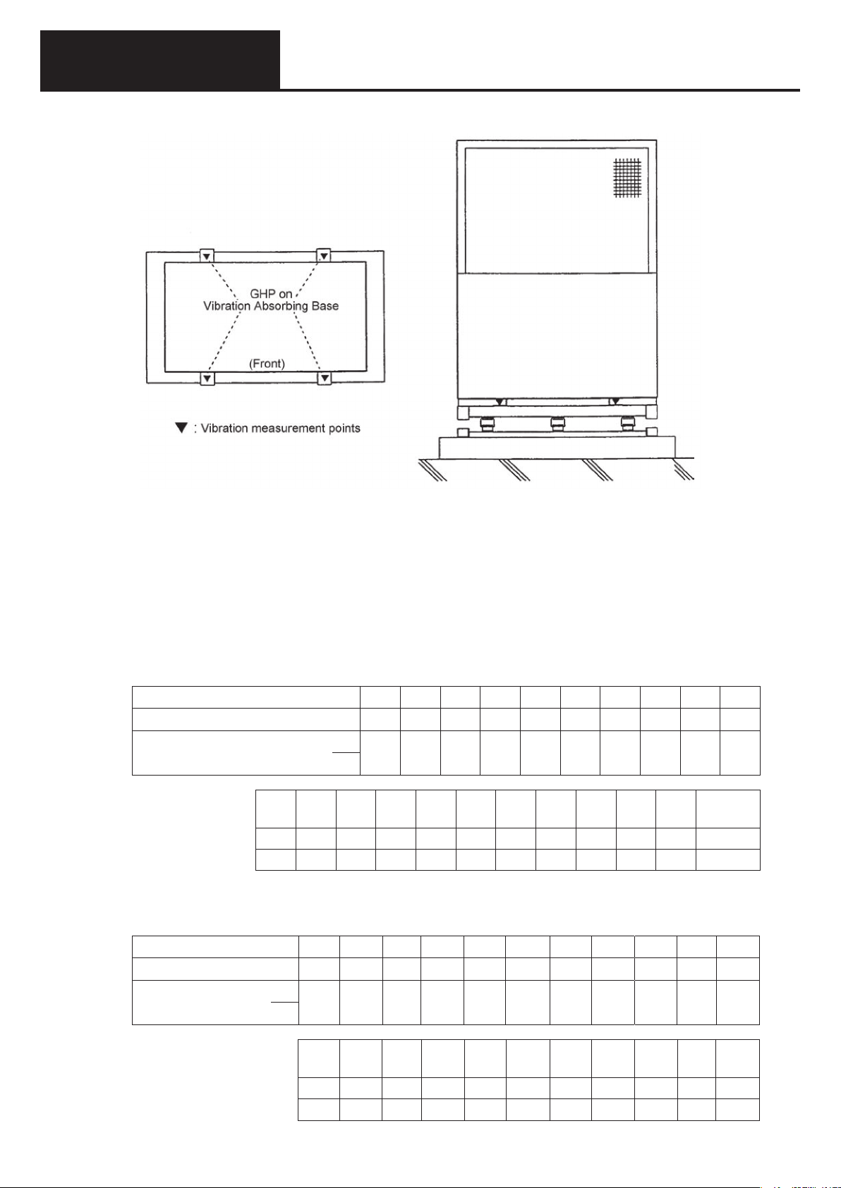
Outdoor Unit
(1) Measurement Points
6. Vibration Force
(2) Vibration Force
Maximum vibration force at each frequency is measured over the whole range of engine rotation speeds
and loads.
For 2-WAY Type
1) Types 45.0/56.0 kW
Maximum values while changing rotation rate from 500 to 2200 r/min.
1/3rd octave
Frequency (Hz)
Vibration force F (N)
Vibration force level 20log
F: Vibration Force (N)
F0: 1N
10
31.5 40 50 63 80 100 125 160 200 250 315
124.5 115.3 374.5 309.7 311.9 274.2 659.2 291.4 747.3 572.1 231.7
41.90 41.24 51.47 49.82 49.88 48.76 56.38 49.29 57.47 55.15 47.30
2) Types 71.0/85.0 kW
Maximum values while changing rotation rate from 500 to 2290 r/min.
Frequency (Hz)
Vibration force F (N)
Vibration force level
20log
10
3.15 4 5 6.3 8 10 12.5 16 20 25 31.5
0.815 1.071 1.49 7.321 19.09 22.01 23.22 200.6 304.5 201 240.7
F
-1.78 0.60 3.46 17.29
F
0
3.15 4 5 6.3 8 10 12.5 16 20 25
0.385 0.035 1.587 2.087 11.3 35.48 49.49 12.25 109.4 95.28
F
-8.28
F
0
-29.21
4.01 6.39 21.06 31.00 33.89
25.61 26.85 27.32 46.05 49.67 46.06 47.63
21.76
40.78 39.58
1/3rd octave
Compound
Value
1386.2
62.8
F: Vibration Force (N)
F0: 1N
40 50 63 80 100 125 160 200 250 315
124.6 341.9 859.8 398.5 890.2 490.2 514.7 468.4 771.8
41.91 50.68 58.69 52.01 58.99 53.81 54.23 53.41 57.75
B-36
254.8
48.12
Compound
Value
1855.0
65.4
Page 43
Outdoor Unit
For 3-WAY Type
1) Types 45.0/56.0 kW
Maximum values while changing rotation rate from 500 to 2200 r/min.
Frequency (Hz)
Vibration force F (N)
Vibration force level 20log
10
6. Vibration Force
3.15 4 5 6.3 8 10 12.5 16 20 25
0.337 0.14 1.296 5.476 43.2 43.15 52.6 243.8 202.5 195
F
-9.44
F
0
-17.10
2.25 14.77 32.71 32.70 34.42
47.74
1/3rd octave
46.13 45.80
F: Vibration Force (N)
F0: 1N
31.5 40 50 63 80 100 125 160 200 250 315
209.7 205.6 536.4 490.3 393.1 998.8 335.4 253.5 371.5 916.2 482.5
46.43 46.26 54.59 53.81 51.89 59.99 50.51 48.08 51.40 59.24 53.67
2) Types 71.0 kW
Maximum values while changing rotation rate from 500 to 2290 r/min.
Frequency (Hz)
Vibration force F (N)
Vibration force level
20log
10
F: Vibration Force (N)
F0: 1N
3.15 4 5 6.3 8 10 12.5 16 20 25 31.5
0.815 1.071 1.49 7.321 19.09 22.01 23.22 200.6 304.5 201 240.7
F
-1.78 0.60 3.46 17.29
F
0
40 50 63 80 100 125 160 200 250 315
124.6 341.9 859.8 398.5 890.2 490.2 514.7 468.4 771.8
41.91 50.68 58.69 52.01 58.99 53.81 54.23 53.41 57.75
25.61 26.85 27.32 46.05 49.67 46.06 47.63
Compound
Value
1816.2
65.2
1/3rd octave
Compound
Value
254.8
1855.0
48.12
65.4
B-37
Page 44

Control-Related
Contents
1. System Block Diagram .......................................................................................C-2
2. Remote Control Warning List
(1) Remote Control Warning List (With Indoor Unit connected) ................................... C-3
3. Circuit Drawing ...................................................................................................C-6
C-1
Page 45
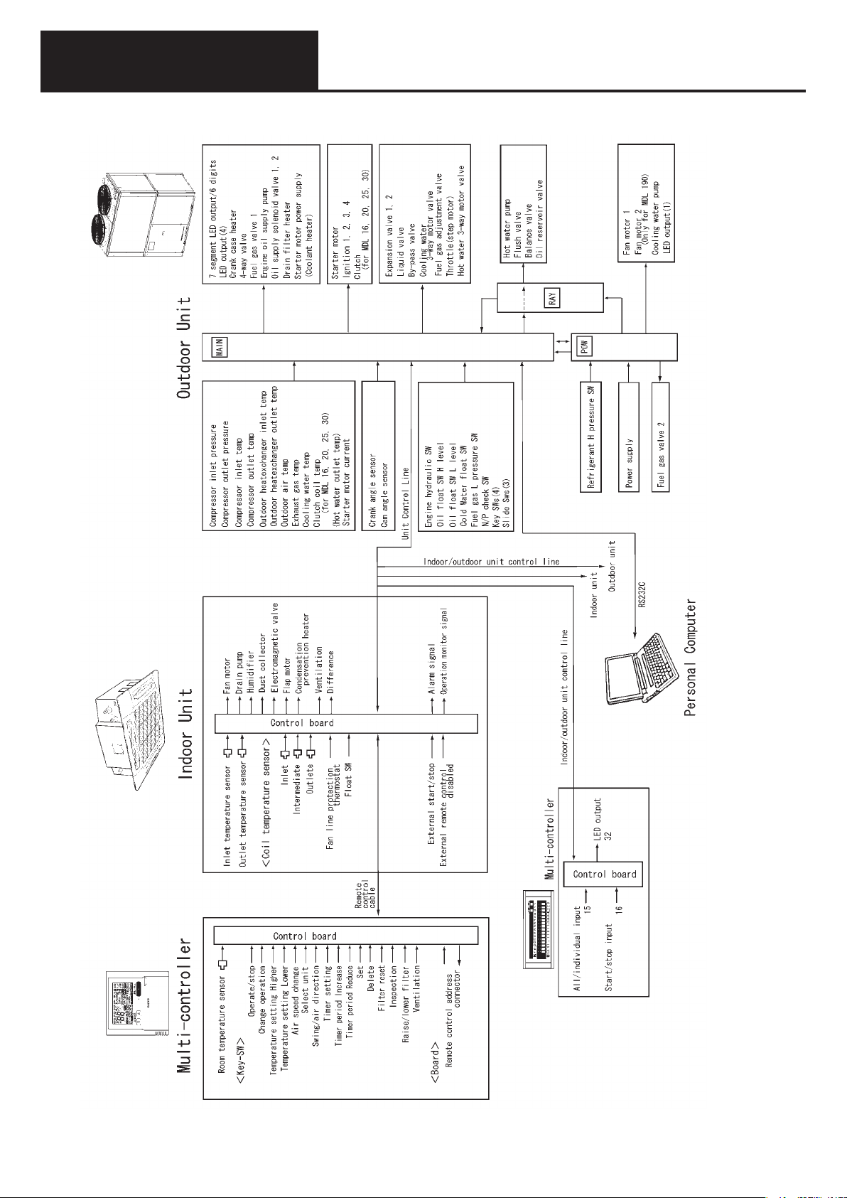
Control-Related
1. System Block Diagram
C-2
Page 46
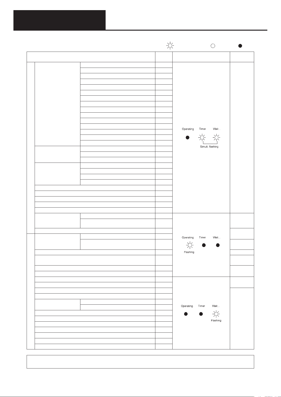
Control-Related
2. Remote Control Warning List
(1) Remote Control Warning List (With Indoor Unit connected)
: Flashing : Lit : Off
Detection Item
Engine oil pressure fault A01
Engine oil fault A02
Engine over-rev fault A03
Engine low-rev fault A04
Ignition power fault A05
Engine start failure A06
Fuel gas valve fault A07
Engine system faults
Engine protection device operation
Starter system faults
Coolant system faults
Clutch fault A25
Catalyzer temperature fault (for only model with catalyzer) A27
Generator fault (for only G-POWER and W Multi models) A28
Converter fault (for only G-POWER and W Multi models) A29
Fuel gas low pressure fault A30
Remote control unit
detected an abnormal
signal from an indoor unit
Faulty reception of (focused) remote control by indoor unit E03
Invalid setting
Faulty reception at indoor unit from signal output board E11 Indoor unit
Serial transmission faults, invalid settings
Automatic address setting is in progress; automatic address setting
start is prohibited
Faulty transmission from an indoor unit to remote control E13
Faulty group control wiring communication E18
Faulty reception by an indoor unit from an outdoor unit E04
Faulty transmission from an indoor unit to an outdoor unit E05
Faulty reception by an outdoor unit from an indoor unit E06
Faulty transmission from an outdoor unit to an indoor unit E07
Automatic address
warning
No indoor unit E20
Outdoor main controller board fault E21
Outdoor main controller board sensor fault E22
Faulty communications between outdoor units (for only W Multi model) E24
Wrong guantity of outdoor units (for only W Multi model) E26
Outdoor unit wrong tubing connection (for only W Multi model) E28
Abnormal transmission within a unit E31
Stalling A08
High exhaust gas temperature A10
Engine oil level fault A11
Throttle failure A12
Oil pressure switch fault A14
Crank angle fault A23
Cam angle fault A24
Accidental fire fault A26
Starter power output short circuited A15
Starter lock A16
CT fault (bad starter current detected) A17
Low coolant temperature A19
High coolant temperature A20
Coolant level fault A21
Coolant pump overload A22
Faulty remote control reception E01
Faulty remote control transmission E02
Duplicate indoor unit address setting E08
Multiple parent remote control settings E09
Too few units E15
Too many units E16
Warning
Display
E12 Outdoor unit
Wireless Remote Control
Lamp Display
Outdoor unit
Indoor unit
Indoor unit
Indoor unit
Outdoor unit
Device
Checked
Remote
controller
Remote
controller
When the water heat exchanger unit is connected in the table above, please replace indoor unit with water
heat exchanger unit for the alarm.
Note: Some items are not indicated, depending in model type.
C-3
Page 47
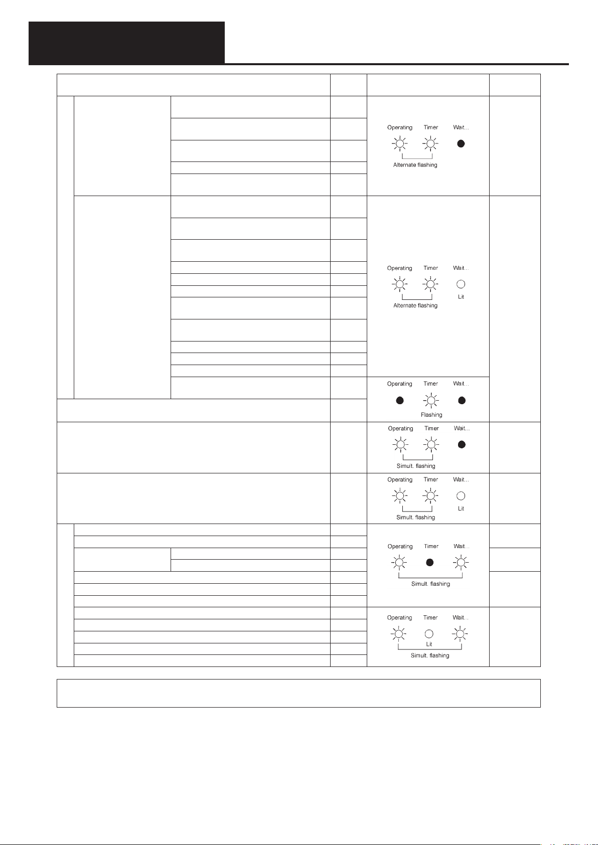
Control-Related
2. Remote Control Warning List
Indoor unit sensor faults
Sensor faults
Outdoor unit sensor
faults
Detection Item
Indoor heat exchanger inlet temperature
sensor fault (E1)
Water heat exchanger refrigerant anti-icing
sensor fault
Indoor heat exchanger outlet temperature
sensor fault (E3)
Indoor unit intake temperature sensor fault F10
Indoor unit blow out temperature sensor
fault
Compressor outlet temperature sensor
fault
Outdoor heat exchanger inlet temperature
sensor fault
Outdoor heat exchanger outlet temperature
sensor fault
External air temperature sensor fault F08
Compressor inlet temperature sensor fault F12
Coolant temperature sensor fault F13
Compressor inlet/outlet pressure sensor
fault
Hot water outlet temperature sensor fault
(for only hot water removal model)
Exhaust gas temperature sensor fault F18
Clutch coil temperature sensor fault F20
Clutch-2 coil temperature sensor fault F21
Oil level sensor fault (for only W Multi
model)
Warning
Display
F01
F02
F03
F11
F04
F06
F07
F16
F17
H08
Wireless Remote Control
Lamp Display
Device
Checked
Indoor unit
Outdoor unit
Compressor oil empty (for only W Multi model) H07
Indoor nonvolatile memory (EEPROM) fault (*1) F29 Indoor unit
Outdoor nonvolatile memory (EEPROM) fault F31 Outdoor unit
Incompatible outdoor/indoor unit (non-GHP equipment connected) L02
Multiple parent devices set for group control L03
Invalid or missing setting
Indoor unit priority
settings duplicated
Group control cable present for individual-control indoor unit L07
Indoor unit address not set L08
Indoor unit capacity not set L09
Duplicate system (outdoor unit) address setting L04
Outdoor unit capacity not set L10
Faulty indoor unit type setting L13
Faulty indoor unit combination L15
Wrong gas type setting L21
Indoor unit priority L05
Non-indoor unit priority L06
Indoor unit
Outdoor unit
Indoor unit
Outdoor unit
When the water heat exchanger unit is connected in the table above, please replace indoor unit with water
heat exchanger unit for the alarm.
Note: Some items are not indicated, depending in model type.
C-4
Page 48
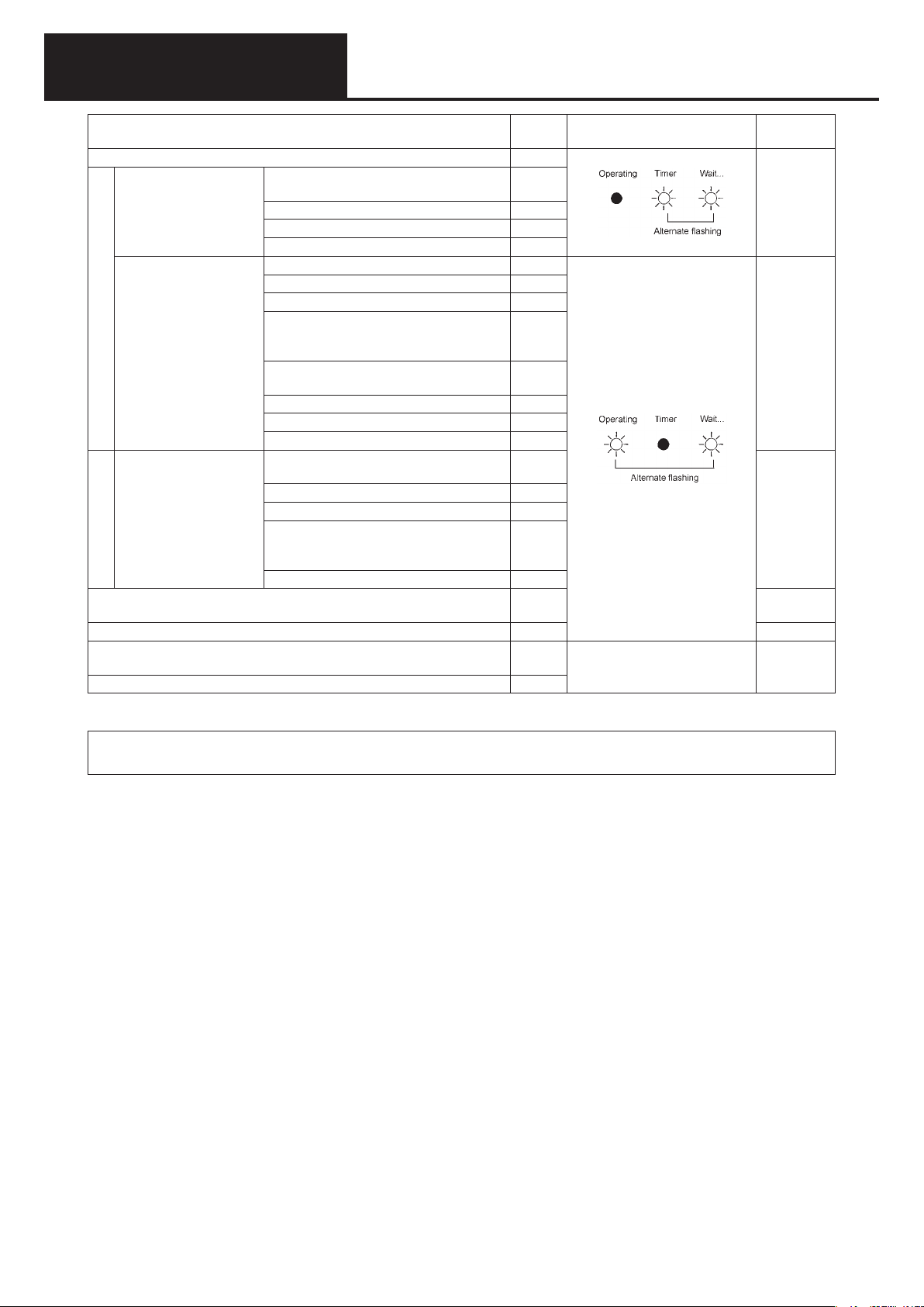
Control-Related
2. Remote Control Warning List
Detection Item
Faulty connection at indoor unit ceiling panel connector P09
Indoor blower fault/
Indoor blower rotation fault
Indoor protection devices
Protection device operation
Outdoor protection
devices
Sub unit of group control fault (System controller) P30
Group control fault (Warning) P31 Indoor unit
Oil replacement time (level) warning
Outdoor display: oil
Automatic backup online (*2) check
Indoor unit float switch fault P10
Indoor unit drain pump error P11
Indoor DC fan fault P12
High compressor discharge temperature P03
Refrigerant high pressure switch action P04
Power supply fault P05
Water heat exchanger freeze fault
(when the water heat exchanger unit is
connected)
Refrigerant circuit fault
(for only W Multi and 3WAY multi)
O2 sensor signal P14
All refrigerant gas lost P15
Bypass valve fault P18
4-Way valve lock fault
(not detected 3WAY Multi)
High refrigerant pressure fault P20
Outdoor blower fault P22
Water heat exchanger unit interlock fault
(for only water heat exchanger unit is
connected)
Clutch engagement fault P26
Warning
Display
P01
P11
P13
P19
P23
Oil
check
Wireless Remote Control
Lamp Display
Device
Checked
Indoor unit
Outdoor unit
System
controller
Outdoor unit
When the water heat exchanger unit is connected in the table above, please replace indoor unit with water
heat exchanger unit for the alarm.
Note: Some items are not indicated, depending in model type.
*1: If the indoor nonvolatile memory (EEPROM) is faulty when the power supply is turned on, warning code
F29 is not indicated, but the power source LED on the indoor board starts to flicker.
*2: In this case, operation of the system is possible, but one of the outdoor units is detected to have stopped
abnormally.
• Warning P30 (group controlled device fault) is sometimes displayed at the system controller.
C-5
Page 49
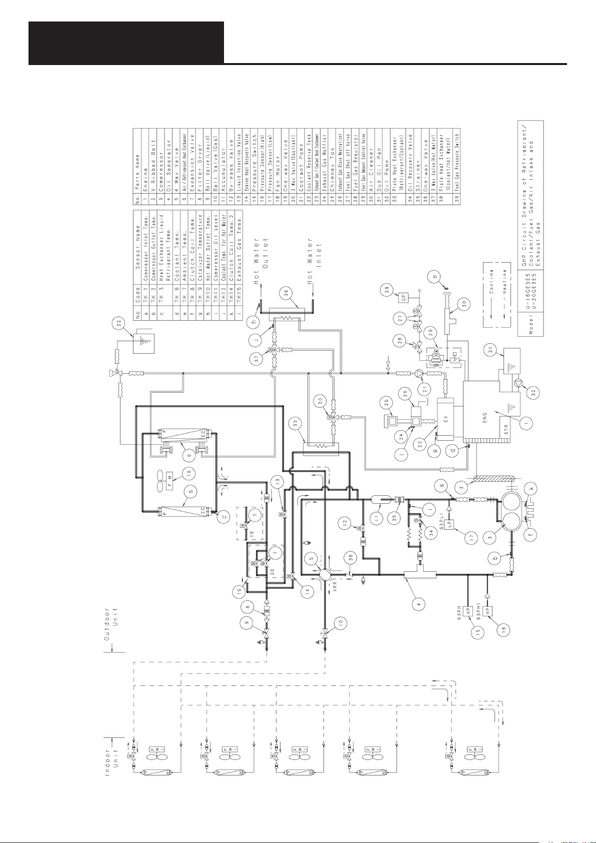
Control-Related
3. Circuit Drawing
C-6
Page 50
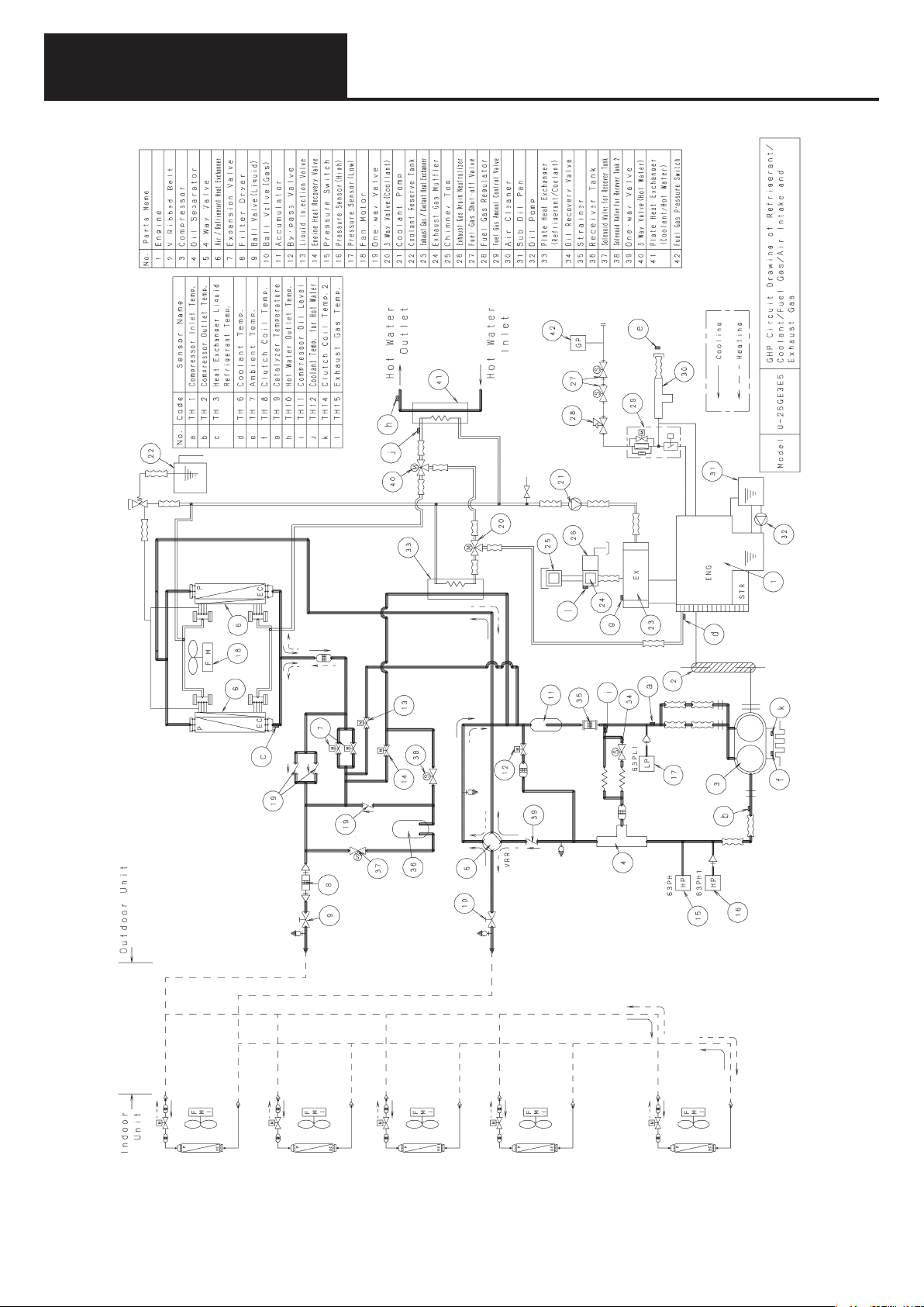
Control-Related
3. Circuit Drawing
C-7
Page 51
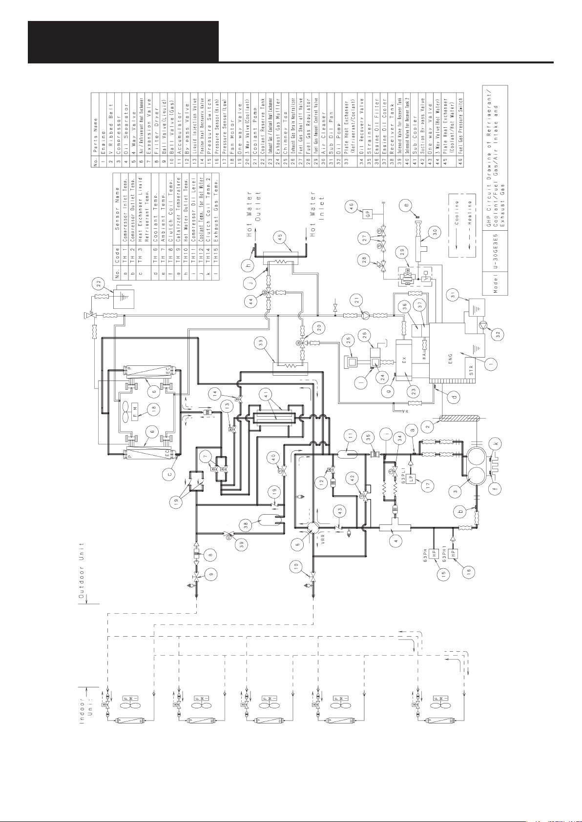
Control-Related
3. Circuit Drawing
C-8
Page 52
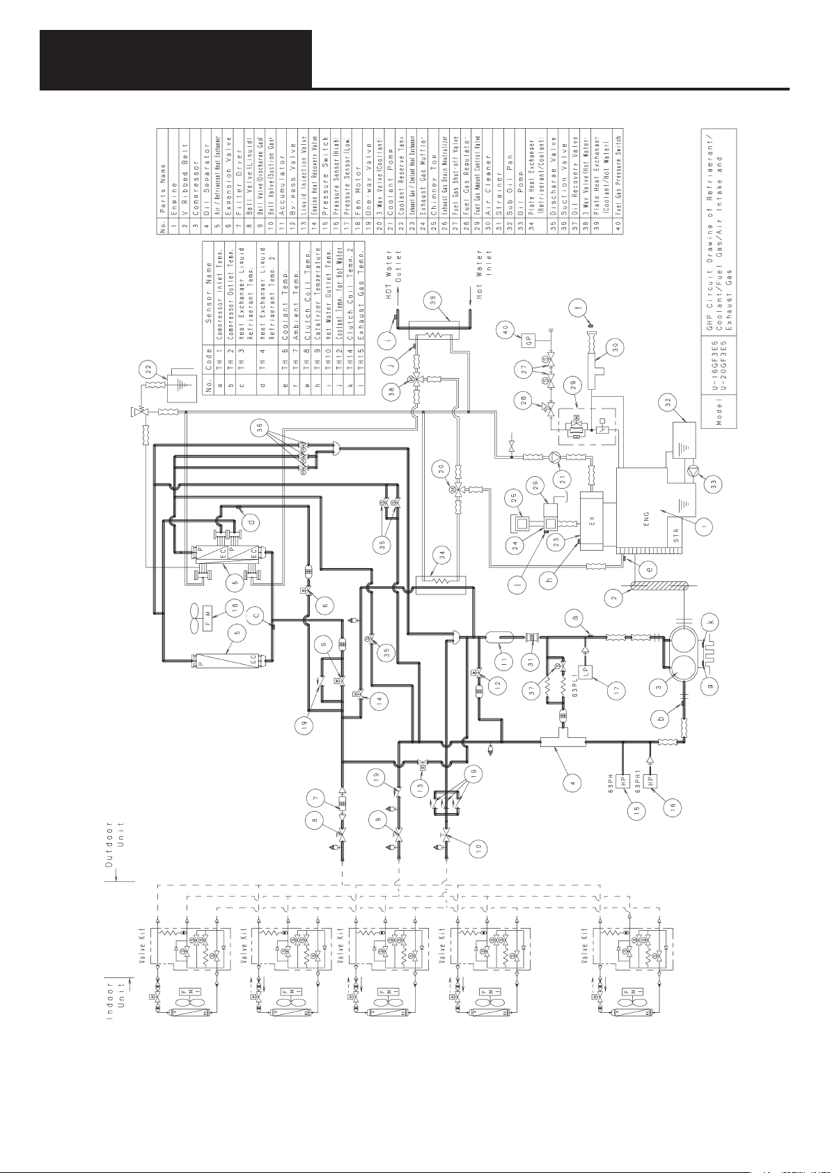
Control-Related
3. Circuit Drawing
C-9
Page 53
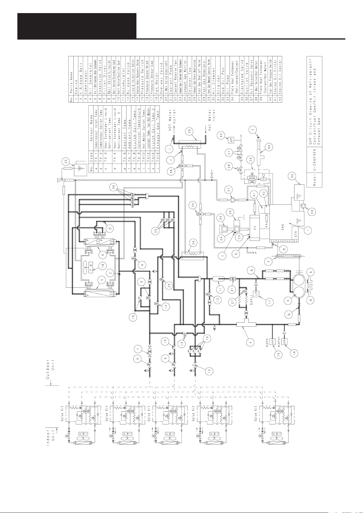
Control-Related
3. Circuit Drawing
C-10
Page 54

System Design
Contents
1. System Configuration
(1) Procedure for selecting model type and calculating performance .......................... D-2
(2) Calculation of actual performance........................................................................... D-3
2. Operating temperature ranges for heating and cooling ......................................D-5
3. Refrigerant piping design
(1) System piping ......................................................................................................... D-6
(2) Selecting system header and branch piping sizes .................................................. D-7
(3) Selecting header piping .......................................................................................... D-8
(4) Selecting branch and header piping........................................................................ D-10
(5) Equivalent length of refrigerant piping ..................................................................... D-16
(6) Calculation of amount of additional refrigerant charge ........................................... D-17
(7) Checking the density limit ....................................................................................... D-18
(8) Future system expansion ........................................................................................ D-19
4. Effect of refrigerant pipe length on performance ................................................D-20
5. Outdoor unit positioning requirements
(1) Combined installation criteria .................................................................................. D-24
(2) Verandah installation criteria ................................................................................... D-31
6. Sound-proofing measures
(1) Installation location and sound-proofing measures ................................................. D-32
(2) Attenuation of sound over distance ......................................................................... D-32
(3) Sound attenuation by a noise barrier ...................................................................... D-33
(4) Additional sound from reflections ............................................................................ D-34
(5) Combining sounds .................................................................................................. D-34
(6) Converting from octave band levels to overall A weighting ..................................... D-35
(7) Designing sound-proofing countermeasures .......................................................... D-35
(8) Sound-proofing calculation sheet (example) ........................................................... D-36
7. Center-of-gravity and earthquake resistance
(1) Earthquake resistance calculations ........................................................................ D-37
(2) Verifying the strength of foundation bolts during an earthquake ............................. D-37
(3) Installation position and center of gravity ................................................................ D-46
(4) Example anchor bolt calculation ............................................................................. D-48
D-1
Page 55
System Design
1. System Configuration
(1) Procedure for selecting model type and calculating performance
Perform the following procedures to select a model type and calculate performance capabilities.
Calculate indoor A/C load
Select A/C system
Design the control system
Select the indoor unit type
Provisionally select indoor/-
outdoor unit combination
Correct performance for
indoor/outdoor performance
ratio
Check piping length and
mounting height difference
between indoor and outdoor
units
Calculate the maximum A/C load for each room or zone.
For each room or zone, select the most suitable air
conditioning method using GHP.
E.g., Individual, centralized or centrally monitored control
(see the section on Control Information document)
Select the appropriate indoor unit type for the A/C system,
e.g., ceiling cassette, all-duct built-in-ceiling, ceiling-mount,
kitchen, or floor-mounted type.
Indoor units with up 130% of outdoor unit capacity can be
connected.
* Up to 24 indoor units can be connected to an outdoor unit.
If the total capacity of the indoor units exceeds outdoor unit
capacity, apply a performance correction.
Because outdoor unit limitations are model-dependent, be
sure to locate the equipment so that the specified tolerances
for refrigerant piping lengths and mounting height difference
are maintained when allocating units.
Correct performance for pipe
length, height difference and
ambient conditions
Reconfirm combined
performance of indoor and
outdoor units
Determine the piping layout
Calculate the additional
charge amount
Design wiring to handle
system capacity
Make performance corrections for ambient air conditions,
piping lengths (effective length), and mounting height
difference.
If a provisionally selected model type is inadequate after
performance corrections, reconsider your configuration.
Design the pipe layout so as to minimize the required
amount of additional refrigerant charge.
If system expansion is contemplated, include those
considerations in the design.
Calculate the amount of additional refrigerant charge
from the diameters and lengths of refrigerant pipes on the
refrigerant pipe system drawing and the unit additional
charge amount.
Check the minimum indoor performance capability and
floor area (density limit) for the amount of refrigerant. If the
density limit is exceeded, reconsider ventilation equipment.
Select wiring capacity according to power supply capabilities.
There are limitations if indoor and outdoor units are powered
from a bus system. If a bus system is employed for the indoor
units, consider including the outdoor unit(s) in the system
as much as possible.
D-2
Page 56
System Design
1. System Configuration
(2) Calculation of actual performance
Indoor units with up 130% of outdoor unit capacity can be connected.
* Up to 24 indoor units can be connected to an outdoor unit.
Multi-unit air conditioning system performance depends on ambient temperature, piping lengths and
mounting height differences, so each correction factor should be taken into account when selecting
the model type.
(1) Dependence of Multi-unit air conditioning system performance on installation conditions
1) Indoor unit cooling capability =
(Outdoor unit rated cooling capacity)
Note 1
× (Indoor unit rated cooling capacity)
÷ (Total rated cooling capacity of the indoor units)
Note 5
Note 3
× (Correction factor for temperature and connected capacity, from performance characteristics)
× (Correction factor for piping length)
Note 8
2) Indoor unit heating capability =
(Outdoor unit rated heating capacity)
Note 2
× (Indoor unit rated heating capacity)
÷ (Total rated heating capacity of the indoor units)
Note 6
Note 4
× (Correction factor for temperature and connected capacity, from the performance characteristics)
× (Correction factor for piping length)
Note 8
Note 1. Outdoor unit rated total cooling capacity (see the outdoor unit specification table) is the
cooling capacity under JIS conditions (indoor side: 27°CDB, 19°CWB, outdoor side: 35°CDB,
-°CWB)
Note 2. Outdoor unit rated total heating capacity (see the outdoor unit specification table) is the
heating capacity under JIS conditions (indoor side: 20°CDB, -°CWB , outdoor side: 7°CDB,
6°CWB)
Note 3. Read the rated cooling capacity of the applicable indoor unit from the indoor unit specification
table.
Note 4. Read the rated heating capacity of the applicable indoor unit from the indoor unit specification
table.
Note 5. Read the rated cooling capacity of the applicable indoor unit from the indoor unit specification
table, and obtain the total for all units..
Note 7
Note 7
Note 6. Read the rated heating capacity of the applicable indoor unit from the indoor unit specification
table, and obtain the total for all units..
Note 7. Read the percentage data at the required temperature from the relevant capacity table in the
“Model Basic Data Table” for the outdoor unit, and divide by 100. (Contact your Panasonic
business representative for the Model Basic Data Table.)
*In the case of two outdoor units, calculate as follows:
Σ (Correction factor for outdoor unit × rated capacity of outdoor unit)
System correction factor =
Σ (Rated capacity of outdoor unit)
Example) Connecting two units (A/C)
α1 = Correction factor of outdoor unit 1, W1 = Rated cooling capacity of outdoor unit 1
α2 = Correction factor of outdoor unit 2, W2 = Rated cooling capacity of outdoor unit 2
System correction factor =
α1 × W1 + α2 × W
W1 + W
2
2
Note 8. Correction factor for piping length
Determine the effective length of refrigerant piping and the mounting height difference
between outdoor and indoor units (positive when the outdoor unit is higher, and negative
when the indoor unit is higher). Read the correction factor from the “Performance correction
for refrigerant piping length” for the outdoor unit, and divide by 100 for percentage.
D-3
Page 57
System Design
(2) Example of calculation of actual performance
[Example calculation conditions]
Indoor units: Six type 112 units, and four type 140 units
Outdoor units: Two type 560 WMulti outdoor units
Indoor/outdoor temperatures: cooling (indoors 22°CWB, outdoors 33°CDB); heating (indoors
22°CWB, outdoors 3°CDB)
Height difference between indoor/outdoor units: Outdoor unit is higher by no more than 50m
Refrigerant effective piping length: 120m
1. System Configuration
1) Indoor unit cooling capability
Outdoor unit rated cooling capacity
Indoor unit rated cooling capacity
Note 1
= 56.0 + 56.0 = 112.0 (kW)
Note 3
Type 112 = 11.2 kW, type 140 = 14.0 kW
Total rated cooling capacity of indoor units
Note 5
= 123.2 (kW)
11.2×6+14.0×4=123.2
From the performance table, the correction factor for temperatures and connected capacity
Note 7
= 1.08
The connected capacity of the indoor units as a percentage of the outdoor capacity is (123.2 ÷ 112.0) × 100 = 110%.
Next obtain the correction factor for each outdoor unit. From the 110% air conditioner capacity
table for each outdoor unit, note the value at the crossover point of the indoor wet bulb temperature
22°CWB and the outdoor air temperature 33°CDB, and then divide the value by 100.
The correction factor for type 560 outdoor units is: 107.9% 1.079
1.079 × 560 + 1.079 × 560
System correction factor = = 1.08
The correction factor for piping length
560 + 560
Note 8
= 0.86
From the “Performance correction for refrigerant piping length” table for the selected unit type, note
the crossover point for the equivalent length of 120m and the height difference of 50m, which is
86%, and divide this by 100.
a) Cooling capacity of each indoor unit
Indoor unit type 112 cooling capability = Note 1 × Note 3 ÷ Note 5 × Note 7 × Note 8
= 112.0 × 11.2 ÷ 123.2 × 1.08 × 0.86
≅ 11.0 kW
Calculating the same way, Type 140 provides 13.7 kW.
b) Total cooling capability of the indoor units is therefore 11.0 × 6 + 13.7 × 4 = 120.8 kW.
2) Indoor unit heating capability
Outdoor unit rated heating capacity
Indoor unit rated heating capacity
Note 1
= 63.0 + 63.0 = 126.0 (kW)
Note 3
Type 112 = 12.5 kW, type 140 = 16.0 kW
Total rated heating capacity of indoor units
Note 5
= 139.0 (kW)
12.5 × 6 + 16.0 × 4 = 139.0
From the performance table, the correction factor for temperatures and connected capacity
Note 7
Indoor unit selection was based upon cooling capacity, so the connected capacity of the indoor
units as a percentage of the outdoor unit capacity is (123.2 ÷ 112.0) × 100 = 130%
Next obtain the correction factor for each outdoor unit. Read the values for 22ºCWB from the 110%
heating capacity table for each outdoor unit, and the value in the table for outdoor temperature of
3ºCDB, and divide by 100.
The correction factor for type 560 outdoor units is: 102.5% 1.025
1.025 × 63.0 + 1.025 × 63.0
System correction factor = = 1.025
The correction factor for piping length
63.0 + 63.0
Note 8
= 0.954
From the “Performance correction for refrigerant piping length” table for the selected unit type, note
the crossover point for the equivalent length of 120m and the height difference of 50m, which is
95.4%, and divide this by 100.
a) Heating capacity of each indoor unit
Indoor unit type 112 heating capability = Note 1 × Note 3 ÷ Note 5 × Note 7 × Note 8
= 126.0 × 12.5 ÷ 139.0 × 1.025 × 0.954
≅ 11.6 kW
Calculating the same way, type 140 provides 14.8 kW.
b) Total heating capability of the indoor units is therefore 11.6 × 6 + 14.8 × 4 = 128.8 kW.
= 1.025
D-4
Page 58
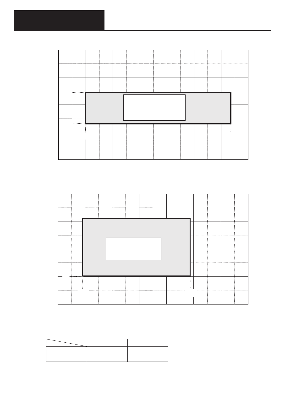
System Design
40
0
(
Outdoor intake air dry bulb temperature (DBºC)
(
40
0
Outdoor intake air wet bulb temperature (WBºC)
Cooling
2. Operating temperature ranges for heating and cooling
WBºC)
Heating
Indoor intake air wet bulb temperature
30
24
20
13.5
10
-
Operating range for cooling
Indoor relative humidity
45-85%
43
40 30 20 10 0 -10 -20 5
Indoor intake air dry bulb temperature
DBºC)
Note 1 : The remote control temperature setting range is as shown in the table below. This is slightly different
Note 2 : When heating starts (during warm-up), the system can operate even if the indoor temperature is below
31
30
20
10
10
from the system operating temperature range.
Cooling 30 18
Heating 30 16
10ºC.
-21
Upper limit Lower limit
Operating range for
heating
D-5
18
30 20 10 0 -10 -20 -30 4
Page 59
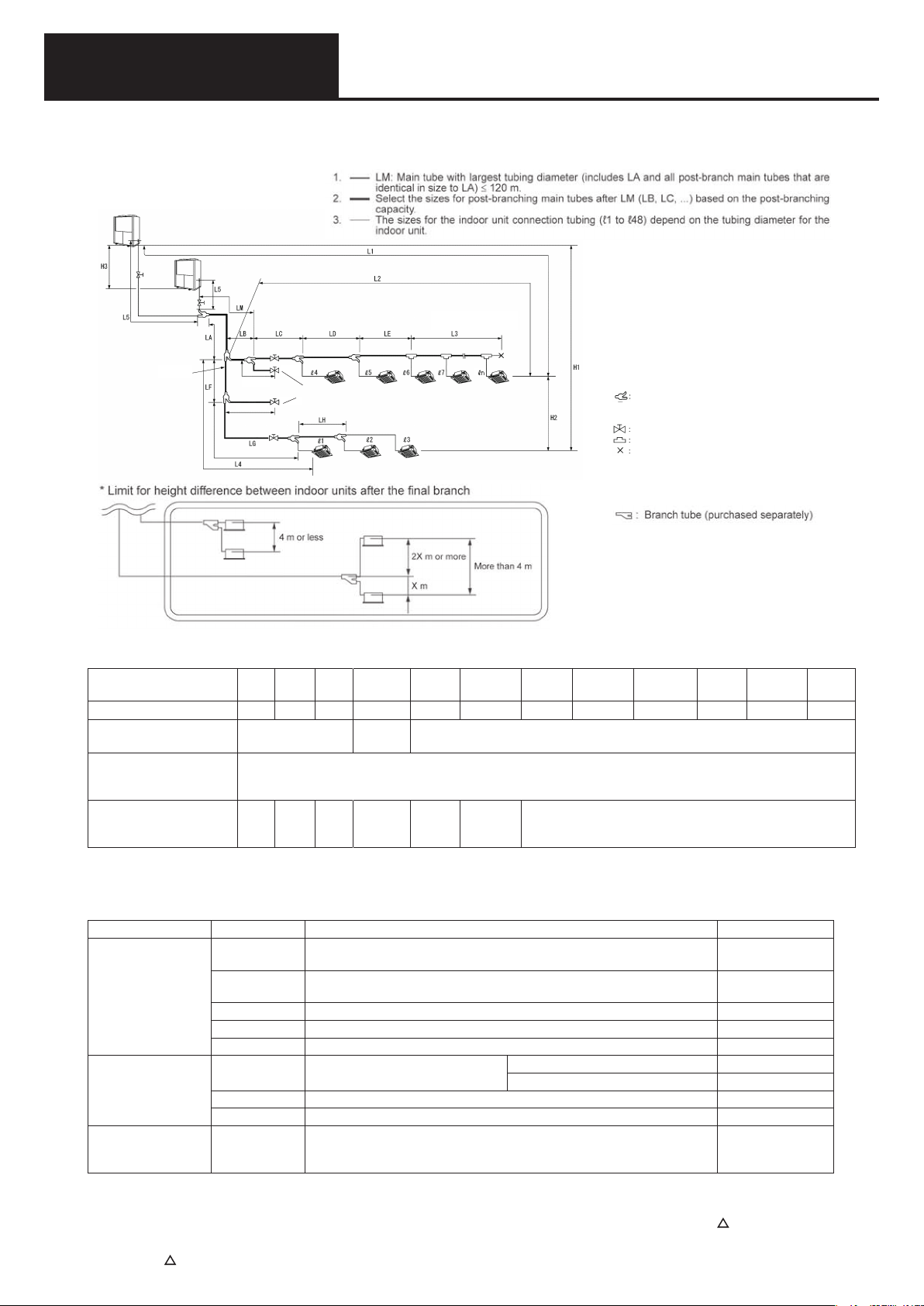
SystemDesign
(1) Systempiping
1) Limitationsonrefrigerantpipinglength
3. Refrigerantpipingdesign
WhenT-teebranchtubingis
used(headerbranchmethod)
No.1branch
40cmorless
40cmorless
2WAYandWMultiModels
Table1-1SystemLimitations
Outdoorunittypesofthe
system
EquivalentHorsepower
Ratioofcapacityforin-
doorunittooutdoorunits
Minimumcapacityof
indoorunitsthatcanbe
connected
Maximumnumberof
indoorunitsthatcanbe
connected(persystem)
45.0 56.0 71.0 85.0
16 20 25 30 32 36 40 41 45 50 55 60
50‒200%
26 33 41 50 52 59 64
Usedfor
expansion
50‒170%
Symbols
Branchtube
(APRpurchasedseparately)
Ballvalve(purchasedseparately)
T-tee(providedbyinstaller)
Closed(pinch)weld
45.0×2 45.0+56.0 56.0×2 45.0+71.0 56.0+71.0 71.0×2 71.0×85.0 85.0×2
Min: Acrossthesystem,aminimumoutdoorunitcapacityof50%
Max:Totalcapacityof130%with2outdoorunits
Type22orgreater(equivalentto0.8horsepower)
2)RangesforRefrigerantTubingLengthandInstallationHeightDifference
Category Symbol Description Tubinglength(m)
≤170(equivalent
length200)
≤70
(*1)
(*2)
≤2
Allowabletubing
length
Allowableheight
difference
Allowablelength
forbranchedtubing
(headerbranch)
L1 Max.allowabletubinglength
∆L=(L2-L4)
LM Max.lengthformaintube(tubewithwidestdiameter) 7≤LM≤120
ℓ1,ℓ2... ℓ48 Max.lengthforeachtubebranch ≤30
L5 Distancebetweenoutdoorunits ≤7
H1
H2 Max.heightdifferencebetweenindoorunits ≤α
H3 Max.heightdifferencebetweenoutdoorunits 1
L3
DifferencebetweenlongestandshortesttubinglengthsaftertheNo.1
branch(firstbranchingpoint)
Max.heightdifferencebetween
indoorandoutdoorunits
Max.lengthbetweenfirstT-teebranch(providedbyinstaller)andthe
closedtubeend
Ifoutdoorunitisabove ≤50
Ifoutdoorunitisbelow ≤35
(*1)Ifcoolingmodeisexpectedtobeusedwhentheexternaltemperatureis10°C orbelow,themaximum
lengthis30m.
(*2)Themax/min permissibleheightbetween indoorunits(α) is foundbythedifference( L) between the
maximumlengthandtheminimumlengthfromthefirstbranch.
α=35- L/2(however,0≤α≤15)
D-6
Page 60
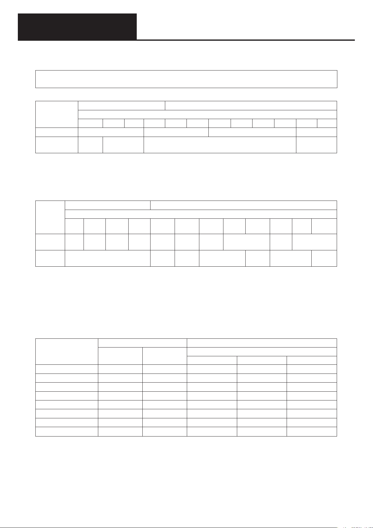
SystemDesign
3.Refrigerantpipingdesign
(2) Selectingsystemheaderandbranchpipingsizes
Outdoorandindoorunitsareconnectedtogetherbyapairofheaders.
Ifthemaximumtubinglengthexceeds90m(effectivelength),increasethesizeofthemaintubingforboth
liquidandgasbyonesize.Becarefulwhenselectingtubesizes,asthewrongsizemayimpairperformance.
1)OutdoorTubing/MainTubeSize
Outdoortubing Maintubing
45 56 71 85 90 101 112 116 127 142 156 170
Gastube(mm) Ø28.58(Ø31.75) Ø31.75(Ø38.1) Ø38.1 Ø38.1(Ø44.45)
Liquidtube(mm)
Ø12.7
(Ø15.88)
Ø15.88
(Ø19.05)
(*1)(*2)
Outdoorunit(gross)capacity(kW)
Ø19.05(Ø22.22) Ø22.22
(*1)Ifthereareplansforfutureexpansion,chooseplumbingsizesaccordingtothetotalcapacityaftersuch
expansion.However,iftubesizeissteppedup3levels,expansionisnotpossible.
(*2)Ifthemaximumtubelengthexceeds90m(orequivalentlength),usethefigureinparentheses()to
sizethemaintubing,alongwiththoseoftheliquidandgastubes.
2)Sizeofmaintubingafterbranch
Whenindoorunit(s)areconnected Maintubeafterbranching
‒5.6 ‒16.0 ‒22.4 ‒28.0 ‒16.0 ‒28.0 ‒35.5 ‒45.0 ‒71.0 ‒101.0 110.5 ‒221.0
Gastube
(mm)
Liquid
tube(mm)
Ø12.7 Ø15.88 Ø19.05 Ø22.22 Ø15.88
Ø9.52 Ø9.52
(*1)(*2)
Post-branchingindoorunitcapacity(kW)*
Ø22.22
(Ø25.4)
Ø9.52
(Ø12.7)
Ø25.4
(Ø28.58)
Ø12.7(Ø15.88)
3
Ø28.58(Ø31.75)
Ø15.88
(Ø19.05)
Ø
31.75
(Ø38.1)
Ø19.05
(Ø22.22)
Ø38.1
(Ø44.45)
Ø22.22
(*1)Selectadiameterforthemaintubingafterabranchthatisnolargerthanthatoftheheader.
(Incaseswherethemaintubingafterabranchwouldhavetobelargerthantheheadertubing,select
tubingofthesamesize,andneverexceedtheheadersize.)
(*2)Ifthemaximumtubelengthexceeds90m(orequivalentlength),usethefigureinparentheses()tosize
themaintubeafterbranching,alongwiththoseoftheliquidandgastubes.
(*3)“‒**”inthetableabovemeans“**kWorless”.
3)Branch/HeaderTubeSelection
Usethefollowingbranchtubingsetsortubingsetsforbranchingthesystemʼsmaintubeandindoorunittubing.
Branchtubesize
Capacityafterbranch
Over72.8kW Ø31.75 Ø19.05 •
Over45.0kWto72.8kW Ø28.58 Ø15.88 • •
Over35.5kWto45.0kW Ø28.58 Ø12.7 • •
Over28.0kWto35.5kW Ø25.4 Ø12.7 • •
Over22.4kWto28.0kW Ø22.22 Ø9.52 • •
Over16.0kWto28.0kW Ø19.05 Ø9.52 • • •
Over5.6kWto16.0kW Ø15.88 Ø9.52 • •
5.6kWorbelow
Gastube(mm) Liquidtube(mm)
(*2)
Ø12.7
(*1) Makeaselectionsoasnottoexceedthemaintubingsize.
(*2) Evenwhen 5.6 kW orbelow,makethegastubediameterØ15.88if2ormoreindoor units are connected after
branching.
(*3) Asthetubediameterforthesuppliedreducerdoesnotmatch,anotherreducermustbeprovidedbytheinstaller.
(*1)
APR-P160BG APR-P680BG APR-P1350BG
Ø9.52 • •
Branchtubenumber
Branchtubing
(*3)
(*3)
(*3)
•
(*3)
•
D-7
Page 61
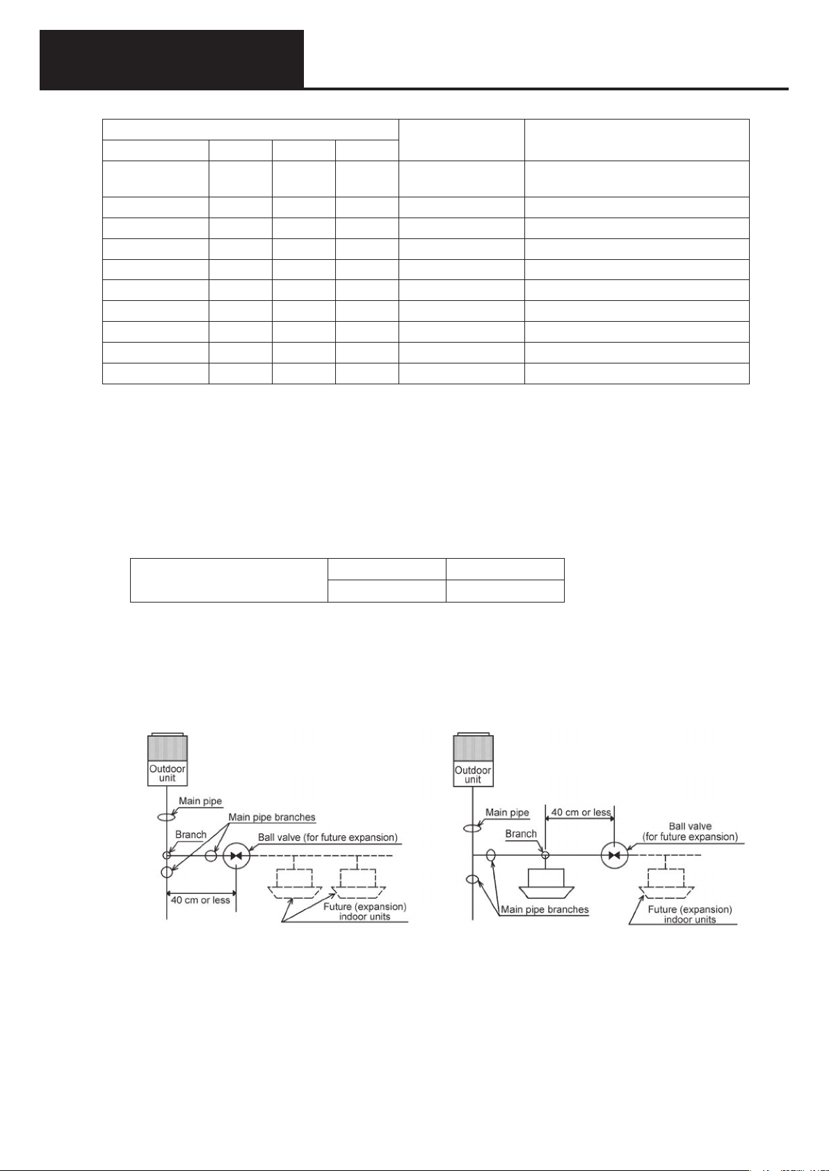
System Design
3. Refrigerant piping design
4) Selecting ball valves
Valve connection tube diameter (mm)
Model Type No. Gas Liquid Balance
SGP-BV710K Ø31.75 Ø19.05 -
SGP-BV450K Ø28.58 Ø19.05 - - Over 35.5 kW to 72.8 kW
SGP-BV355K Ø28.58 Ø15.88 - 56.0, 71.0 kW Type Over 45.0 kW to 72.8 kW
SGP-BV450M Ø28.58 Ø12.7 - 45.0 kW Type Over 35.5 kW to 45.0 kW
BV-RXP335AGB Ø25.4 Ø12.7 - - Over 28.0 kW to 35.5 kW
BV-RXP280AGB Ø22.22 Ø9.52 - - Over 22.4 kW to 28.0 kW
BV-RXP224AGB Ø19.05 Ø9.52 - - Over 16.0 kW to 22.4 kW
BV-RXP160AGB Ø15.88 Ø9.52 - - Over 5.6 kW to 16.0 kW
BU-RXP56AGB Ø12.7 *
BV-RP3GB Ø9.52 For balance tube
2
Ø6.35 - - 5.6 kW or less
*1
Applicable outdoor
unit
71.0 kW Type
(over 90 m)
Applicable indoor unit
Total indoor unit capacity through valve
Over 72.8 kW to 101.0 kW
Note 1. The ID of these valves is about the same as that of the connecting copper tube, so no correction
for pressure loss is necessary.
Note 2. Leakage pressure rating must be at least 4.15 MPa.
*1. Select a size that does not exceed header size.
*2. Even for 5.6 kW or less, if the indoor unit tubing branches, use 15.88 mm diameter gas tube.
(3) Selecting header piping
Connect outdoor and indoor units together using a pair of header tubes.
1) Pipe diameters
Header tube (LM) diameter
1
(mm)*
Gas tube Liquid tube
Ø31.75 Ø19.05
Note: The balance tube (tube between outdoor units) is 9.52 mm dia.
*1. If the maximum tubing length (L1) exceeds 90m (equivalent length), increase the size of the main
piping for both liquid and gas by one size. However, gas tube diameter should not exceed 38.1 mm.
(Reducers are available locally.)
[Anticipating additional indoor units]
1) Ball valve installation position: Install on main piping after branching.
2) Installation guidelines
• Slope main pipes after branches so as to prevent oil buildup.
• Locate ball valves as close as possible to (within 40 cm) of their branch points.
• If the pipe diameter at the ball valve is smaller than that of the main pipe after branching, install
reducers only at the ball valve connections.
• Locate the equipment where it will be easy to operate and inspect in the future.
Caution
When installing indoor piping (including that for future indoor expansion) along a main pipe after a
branch, be sure to position service ports to face in the direction of their units (see dashed lines in the
example above).
D-8
Page 62
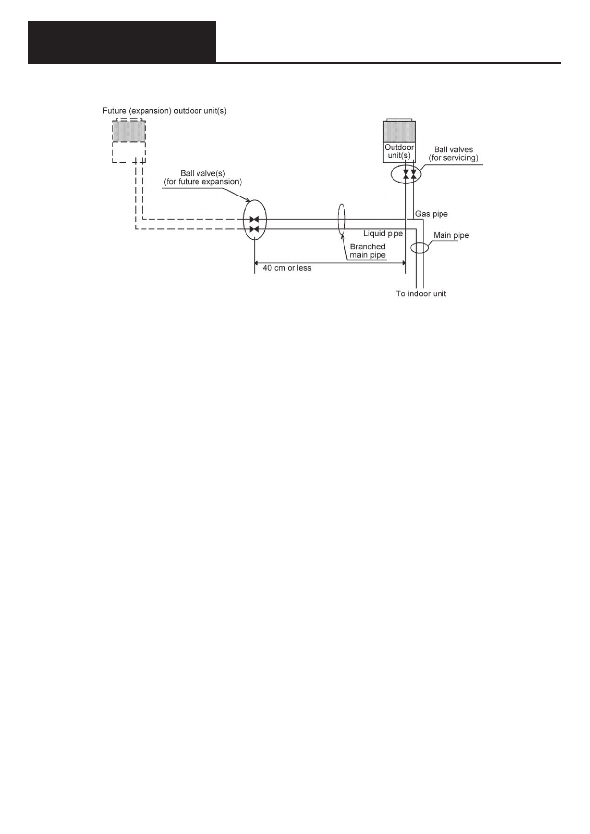
System Design
[Anticipating additional outdoor units]
1) Ball valve installation position: Install on main piping after branching.
2) Installation guidelines
• Slope main pipes after branches so as to prevent oil buildup.
• Locate ball valves as close as possible to (within 40 cm) of their branch points.
• If the pipe diameter at the ball valve is smaller than that of the main pipe after branching, install
reducers only at the ball valve connections.
Caution
When installing outdoor piping (including that for future indoor expansion), be sure to position the valve
service port to face in the direction of the outdoor unit (see dashed lines in the example above), and
at least 50 cm from the outdoor unit.
3. Refrigerant piping design
D-9
Page 63
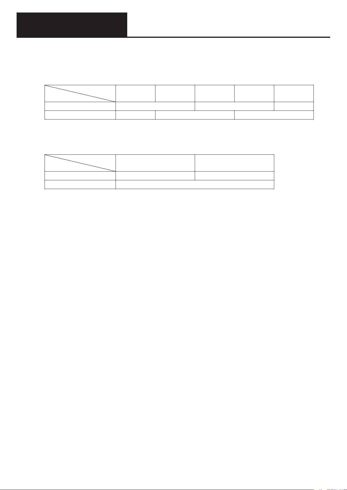
System Design
3. Refrigerant piping design
(4) Selecting branch and header piping
1) When a branch pipe set is used
Select the branch set from the following table.
* For details, see the section on items sold separately.
Total capacity
Max. piping length
Up to 90m equivalent length APR-P160BG APR-P680BG APR-P1350BG
Over 90m equivalent length APR-P160BG APR-P680B APR-P1350BG
2) Header piping sets
Select the header piping set from the following table.
* For details, see the section on items sold separately.
Total capacity
Max. piping length
Up to 90m equivalent length SGP-HCH280K SGP-HCH560K
Over 90m equivalent length SGP-HCH560K
* When maximum piping length (L1) exceeds 90m (equivalent length), or if interior unit connected capacity
exceeds 130% of outdoor unit capacity, increase the diameter of both liquid and gas pipes (LA) by one
size.
Be careful when selecting pipe sizes, as the wrong size may impair performance.
Up to 16 kW 16.1 – 22.4 kW 22.5 – 35.5 kW 35.6 – 45.0 kW 45.1+ kW
45.0 kW Type
56.0 kW and 71.0 kW
and 85.0 kW Type
D-10
Page 64
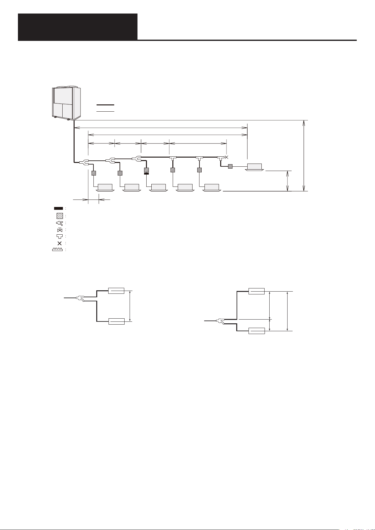
System Design
3WAY Multi Models
(1) Limitations on refrigerant piping length
Outdoor unit
3-tube line (discharge gas tube, suction gas tube, liquid tube)
2-tube line (gas tube, liquid tube)
LA
LB
First branch
(Branch line)
ℓ1
LC
ℓ2
LD L4
ℓ3
L1
L2
When T-tee branch tubing is used
(header branch method)
ℓ4
ℓ
3. Refrigerant piping design
H1
ℓn
n-1
H2
L3
Externally mounted solenoid valve kit (sold separately)
Solenoid valve kit (purchased separately)
Branch tube (purchased separately)
Ball valve (purchased separately)
T-tee (provided by installer)
Closed (pinch) weld
Header (purchased separately)
Indoor unit
CAUTION : 1) Each indoor unit requires a solenoid valve kit.
2) Never branch the tube between a solenoid valve kit and indoor unit.
3) Never branch the tube again after the header branching.
4) If using an external electric valve kit, install it between the solenoid
(2) Difference in height of Indoor units after last branch
Height difference between indoor units after the final branch must be less than 4 m.
4 m or less
If height difference between indoor units after the final branch cannot be less than 4 m,
divide the height difference between upper and lower units (2 to 1).
valve kit and the indoor unit.
2X m or
more
X m
More than 4 m
D-11
Page 65
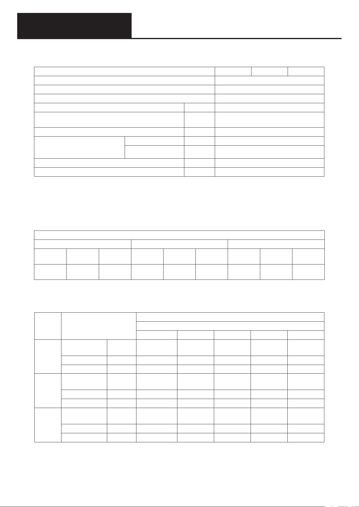
System Design
3. Refrigerant piping design
(3) Selecting system header and branch piping sizes <for 3WAY Multi Models>
Table 1. Refrigerant tubing length and range of rise/fall
Indoor unit 45.0 kW 56.0 kW 71.0 kW
Capacity proportion of the indoor units to the outdoor unit 50 - 200 %
Minimum capacity of indoor units that can be connected ≤ 22 type (equivalent to 0.8 horsepower)
Maximum number of indoor units (systems) that can be connected 24
Maximum allowable tubing length (L) L
Difference between longest and shortest tubing lengths after
the No. 1 branch (first branching point)
Maximum length of each tube branch ℓ1, ℓ2...ℓ8 ≤ 30 m
Maximum allowable height difference between indoor and outdoor
units
Maximum allowable height difference between indoor units H
Maximum length from the first T-tee to the last T-tee L
If outdoor unit is above H
If outdoor unit is below H
1
L2 - L
1
2
3
3
≤ 120 m (equivalent length ≤ 145 m)
8
≤ 30 m
≤ 50 m
≤ 35 m
≤ 15 m
≤ 2 m
(*2)
(*3)
(*1) The minimum length of tubes between outdoor units and indoor units is 7 m.
(*2) If cooling mode is expected to be used when the external temperature is 10°C or below, install so the
maximum length is 30 m.
(*3) Install so that the height difference between indoor units after the final branch is within the limits shown in
Fig 3.
(*1)
Table 2. Main Piping Diameter
Main Tubing Diameter
45.0 kW Type 56.0 kW Type 71.0 kW Type
Suction
Tube
Ø28.58
(Ø31.75)
Discharge
Tube
Ø22.22 Ø19.05
Liquid
Tube
Suction
Tube
Ø28.58
(Ø31.75)
Discharge
Tube
Ø25.4 Ø19.05
Liquid
Tube
Suction
Tube
Ø28.58
(Ø31.75)
Discharge
Tube
Ø25.4 Ø19.05
Liquid
Tube
If the equivalent length of piping is 90m or more or if the total capacity for connected indoor units exceeds
130% use the suction tube size in ( ).
Table 3. Main tubing size after distriburion (D2, D3, Dn)
Outdoor
unit
45.0 kW
Type
56.0 kW
Type
71.0 kW
Type
Outdoor tubing (mm)
35.6 to 142.0 28.1 to 35.5 16.1 to 28.0 9.0 to 16.0 Under 9.0
Suction tube
Discharge tube Ø22.22 Ø22.22 Ø22.22 Ø19.05 Ø15.88 Ø12.7
Liquid tube Ø19.05 Ø15.88 Ø15.88 Ø12.7 Ø9.52 Ø9.52
Suction tube
Discharge tube Ø25.4 Ø25.4 Ø22.22 Ø19.05 Ø15.88 Ø12.7
Liquid tube Ø19.05 Ø19.05 Ø15.88 Ø12.7 Ø9.52 Ø9.52
Suction tube
Discharge tube Ø25.4 Ø25.4 Ø22.22 Ø19.05 Ø15.88 Ø12.7
Liquid tube Ø19.05 Ø19.05 Ø15.88 Ø12.7 Ø9.52 Ø9.52
Ø28.58
(Ø31.75)
Ø28.58
(Ø31.75)
Ø28.58
(Ø31.75)
Ø28.58
(Ø31.75)
Ø28.58
(Ø31.75)
Ø28.58
(Ø31.75)
Total capacity for connected indoor units (kW)
Post-branch main tubing
Ø28.58 Ø25.4 Ø19.05 Ø15.88
Ø28.58 Ø25.4 Ø19.05 Ø15.88
Ø28.58 Ø25.4 Ø19.05 Ø15.88
*1 If anticipating future expansion, select tube diameters according to total capacity after expansion.
*2 If the maximum tubing length exceeds 90 m (equivalent length), increase the diameter of the main tubing
to the size in ( ) for both liquid and gas tubes. However, gas tube diameter should not exceed 31.75 mm.
(Reducers are available locally.)
D-12
Page 66
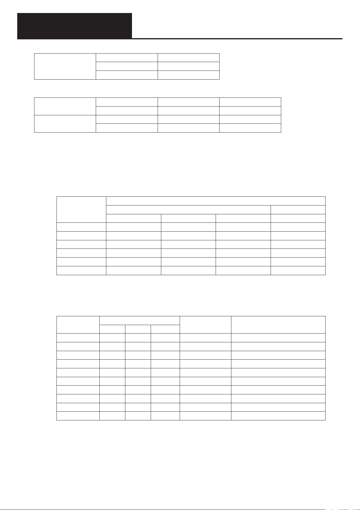
System Design
3. Refrigerant piping design
Table 4. Distribution ⇔ Solenoid valve kit connection piping (3-tube line) <for 3WAY Multi Models>
Suction tube Ø15.88
Tubing size (mm)
Discharge tube Ø12.7
Liquid tube Ø9.52
Table 5. Solenoid Valve Kit ⇔ Indoor unit connection piping (2-tube line)
Indoor unit
Tubing size (mm)
Unit Type 22-56 kW 60-160 kW
Equivalent Horsepower 0.8-2.0 2.5-6.0
Gas tube Ø12.7 Ø15.88
Liquid tube Ø6.35 Ø9.52
*1 The flare connection method is join Solenoid Valve Kit (option) and the indoor units. Please refer to the
operation manual.
(4) Branch Pipe and Ball Valve Selection
(1) Branch pipe selection
From the following branch and header pipe sets, select the applicable model for branches from the
system main pipe and indoor unit piping.
Capacity after
branch (kW)
45.1 – 142.0 –
35.6 – 45.0 –
28.1 – 35.5 –
16.1 – 28.0 –
9.0 – 16.0
<9.0
APR-RZP224BGB APR-RZP680BGB APR-RZP1350BGB SGP-HCHZ560M
Not usable when the maximum piping length exceeds 90m (equivalent length) or the connected
indoor capacity exceeds 130%.
Make arrangements locally if the pipe diameters do not match.
Branch pipe model number
Branch pipe set Header pipe set
(2) Ball valve selection
Model No.
SGP-BV710K Ø31.75 Ø19.05 – – Over 72.8 – 101.0 kW
SGP-BV450K Ø28.58 Ø19.05 – 45.0 ~ 71.0 kW Type Over 35.5 – 72.8 kW
SGP-BV355K Ø28.58 Ø15.88 – – Over 45.0 – 72.8 kW
SGP-BV450M Ø28.58 Ø12.7 – – Over 35.5 – 45.0 kW
BV-RXP335AGB Ø25.4 Ø12.7 – – Over 28.0 – 35.5 kW
BV-RXP280AGB Ø22.22 Ø9.52 – – Over 22.4 – 28.0 kW
BV-RXP224AGB Ø19.05 Ø9.52 – – Over 16.0 – 22.4 kW
BV-RXP160AGB Ø15.88 Ø9.52 – – Over 5.6 – 16.0 kW
BU-RXP56AGB Ø12.7
SGP-BVZ280K – – Ø19.05 For discharge pipe
Valve connection pipe diameter
Suction Liquid Discharge
*2
Ø6.35 – – 5.6 kW or less
*1
Applicable Outdoor
Unit
Applicable Indoor Unit
Total indoor unit capacity through valve
Note 1. The inside diameter of these valves is about the same as that of the connecting copper pipe,
so no correction for pressure loss is necessary.
Note 2. Leakage pressure rating must be at least 4.15 MPa.
*1. Select a size that does not exceed header size.
*2. Even for 5.6 kW or less, if the indoor unit piping branches, use 15.88 mm diameter gas pipe.
D-13
Page 67
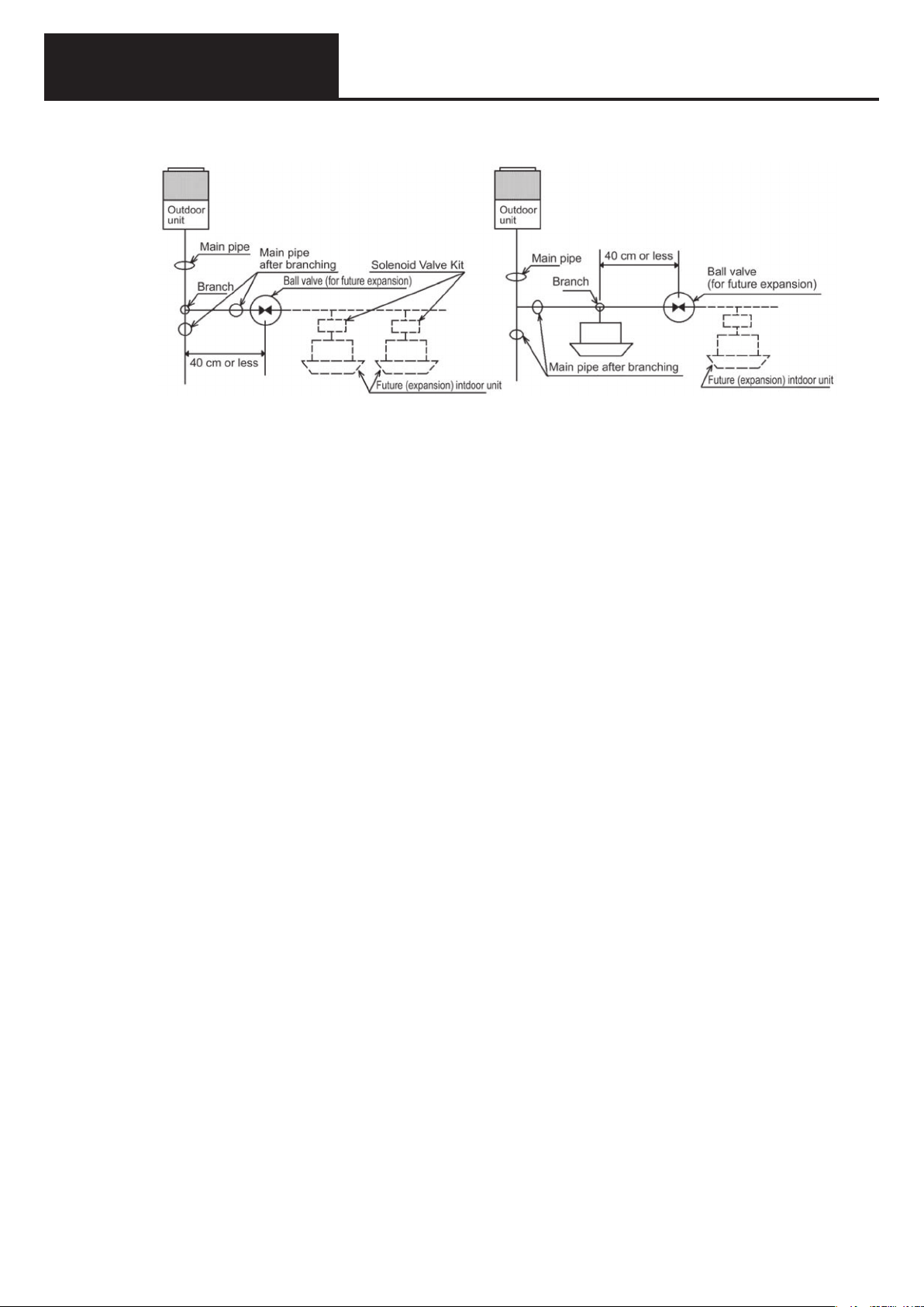
System Design
3. Refrigerant piping design
[Anticipating additional indoor units] <for 3WAY Multi Models>
1) Ball valve installation position: Install on main piping after branching.
2) Installation guidelines
* Slope main pipes after branches to prevent oil buildup.
* Locate ball valves as close as possible to within 40 cm of their branch points. If the pipe diameter
at the ball valve is smaller than that of the main pipe after branching, install reducers only at the
ball valve connections.
* Locate the equipment where it will be easy to operate and inspect in the future.
Caution
* When installing indoor piping (including that for future indoor expansion) along a main pipe after a
branch, be sure to position service ports to face in the direction of their units (see dashed lines in the
example above).
* Install a service port between the branch and solenoid valve kit, and with additional solenoid valve kits
when expanding indoor units.
D-14
Page 68
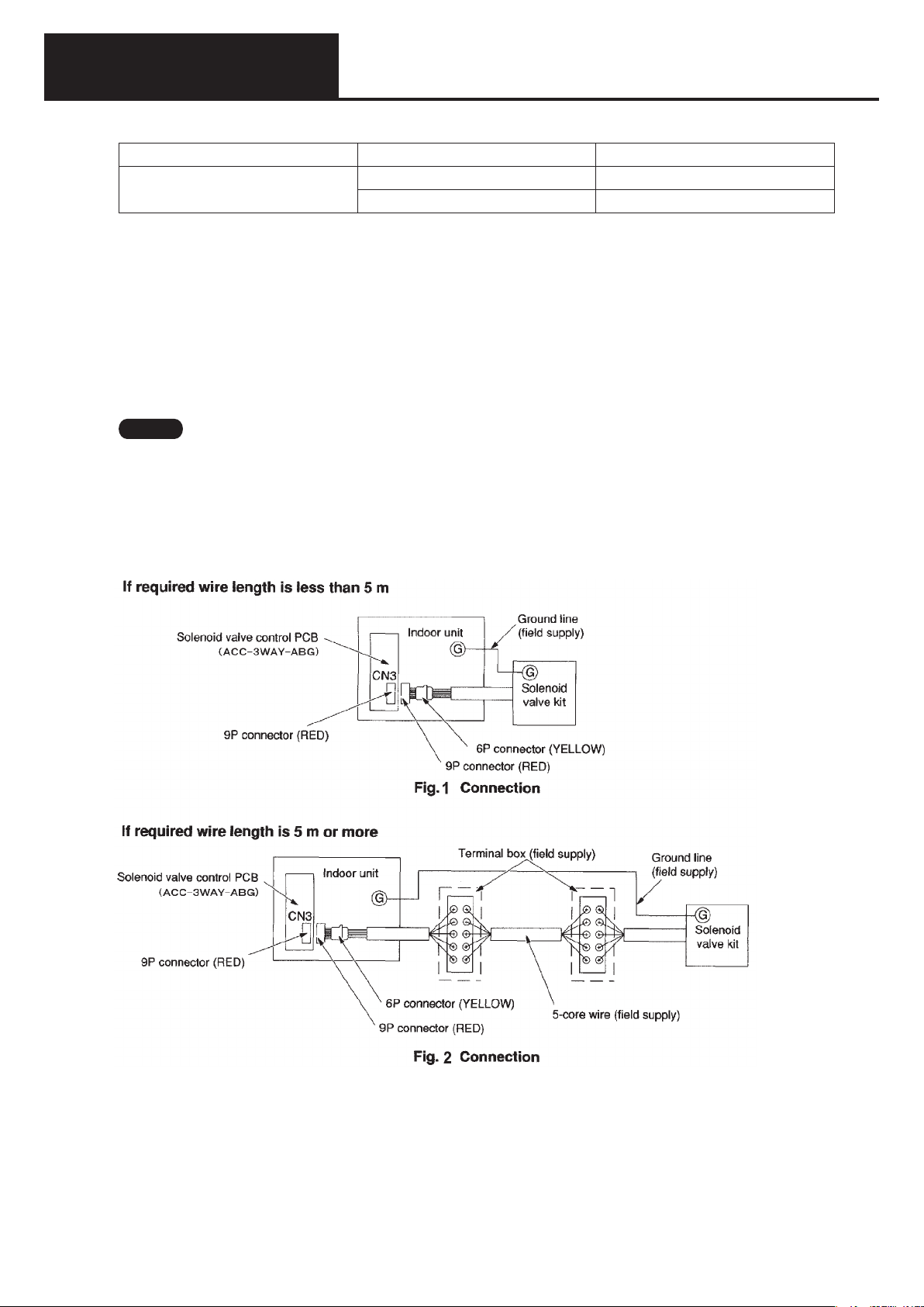
System Design
Note
3. Refrigerant piping design
(4) Solenoid Valve Kits (sold separately) <for 3WAY Multi Models>
Model Name Model No. Compatible Indoor Units
Solenoid Valve Kit
Wiring Procedure
Connect the 9P connector coming from the solenoid valve kit through the power inlet of the indoor unit to
the 9P connector (red) of the 3 WAY PCB (sold separately). (Fig. 1)
Accessory wire length is 5 m.
In case the wire is not long enough, cut the wire halfway and connect additional wire (field supply) as an
extension using a terminal box (field supply) as shown in Fig. 2.
Anchor the cabtyre cable using the binding bands inside the unit.
Do not route the cabtyre cable through the same wiring conduit as the remote controller wiring or inter-unit
control wiring.
You must follow your local electrical codes.
The wire should be fixed with the clamp inside the indoor unit.
Do not route the wire through a tube together with the remote-control line and inter-unit operation line run.
Recommended wire size
5-core cable, 0.75 mm2 or more (300 V or more)
Grounding should be done between the indoor unit and solenoid valve kit.
CZ-P56HR2 Types 22 to 56
CZ-P160HR2 Types 71 to 160
D-15
Page 69
System Design
3. Refrigerant piping design
(5) Equivalent length of refrigerant piping
The following table shows the equivalent straight piping length of connectors that may be used in the piping
system.
Table 3. Equivalent straight piping length of connectors
Inlet pipe or thick pipe
(gas pipe)
90º elbow 0.15 0.3 0.35 0.42 0.48 0.52 0.57 0.7 0.79
45º elbow 0.1 0.23 0.26 0.32 0.36 0.39 0.43 0.53 0.59
T-tee 0.2 0.5 0.5 0.6 – 0.8 0.9 0.9 –
Socket 0.05 0.1 0.11 0.12 – 0.14 0.16 0.18 –
U bend (R60 -100mm) 0.7 0.9 1.05 1.26 1.44 1.56 1.71 2.1 2.37
Trap bend 1.8 2.3 2.8 3.2 3.8 4.3 4.7 5.0 5.8
Branch pipe 0.5
Header pipe 1
Ball valve for service Not applicable to equivalent length calculation
Table 4. Equivalent straight piping length of bent pipe
Ø9.52 Ø12.7 Ø15.88 Ø19.05 Ø22.22 Ø25.4 Ø28.58 Ø31.75 Ø38.1
Units (m)
R
d
0.5 25.0×d 40.0×d 53.5×d
1.0 12.0×d 18.5×d 25.8×d
1.5 7.8×d 12.2×d 16.4×d
2.0 6.4×d 10.0×d 13.4×d
2.5 5.9×d 9.2×d 12.3×d
3.0 5.7×d 9.0×d 12.0×d
3.5 5.9×d 9.2×d 12.2×d
4.0 6.4×d 10.0×d 13.4×d
4.5 7.1×d 11.0×d 14.8×d
45º bend 90º bend 180º bend
Equivalent length
Calculation example
R
d: OD R: Bend radius
Example:
For a 19 mm dia. Pipe bent 90º with 30 mm radius
(d=19 · R=30)
From the table,
Length = 12.2 x 19 =231 mm
The result is 0.23
30
=
19
=1.57
d
D-16
Page 70
System Design
3. Refrigerant piping design
(6) Calculation of amount of additional refrigerant charge
1) Table 2 shows the refrigerant charge at factory shipping time. Additional refrigerant must be added
according to the size and length of the piping (calculated from the size and diameter of the liquid piping
using the values in Table 1).
Table 1. Quantity of additional refrigerant charge
Liquid tube size (mm)
Ø6.35 26 45.0 kW
Ø9.52 56 56.0 kW
Ø12.7 128 71.0 kW
Ø15.88 185 85.0 kW
Ø19.05 259
Ø22.22 366
Additional charge
quantity per meter (g/m)
Required additional refrigerant charge (g) =
Table 2.
456 × (A) + 366 × (B) + 259 × (C) + 185 × (D) + 128 × (E)
+ 56 × (F) + 26 × (G) + Unit additional charge amount (H)
(A) = total length in meters of 25.4 mm diameter liquid tubing
(B) = total length in meters of 22.22 mm diameter liquid tubing
(C) = total length in meters of 19.05 mm diameter liquid tubing
(D) = total length in meters of 15.88 mm diameter liquid tubing
(E) = total length in meters of 12.7 mm diameter liquid tubing
(F) = total length in meters of 9.52 mm diameter liquid tubing
(G) = total length in meters of 6.35 mm diameter liquid tubing
(H) = Unit additional charge amount (Table 7)
Type
Table 3.
Quantity of refrigerant
charge when shipped (kg)
11.5
Type
45.0 kW 0.5
56.0 kW 3.5
71.0 kW 9.5
85.0 kW 9.5
Unit additional
charge amount (kg)
2) Be careful to charge accurately according to refrigerant weight.
3) Charging procedure
Evacuate the system, close the gauge manifold at the gas pipe side to ensure that no refrigerant enters
the gas pipe side, then charge the system with liquid refrigerant at the liquid pipe side. While charging,
keep all valves fully closed.
The compressor can be damaged if liquid refrigerant is added at the gas pipe side.
4) If the system does not accept the predetermined quantity of refrigerant, fully open all valves and run
the system (either heating or cooling). While the system is running, gradually add refrigerant at the low
pressure side by slightly opening the valve on the cylinder just enough so that the liquid refrigerant is
gasified as it is sucked into the system. (This step is normally only needed when commissioning the
system.)
All outdoor unit valves should be fully open.
5) When charging is completed, fully open all valves.
6) Avoid liquid back-flow when charging with R410A refrigerant by adding small amounts at a time.
Notes
• When charging with additional refrigerant, use liquid only.
• R410A cylinders are colored gray with a pink top.
• Check whether a siphon pipe is present (indicated on the label at the top of the cylinder).
• Depending on refrigerant and system pressure, conventional refrigerant (R22, R407A) equipment may
or may not be compatible with R410A equipment, so care is needed. In particular, the gauge manifold
used must be specifically designed for R410A.
• Be sure to check the limiting density.
• Refer to the section “Opening the shut-off valves” when the instructions call for fully opening all valves.
D-17
Page 71
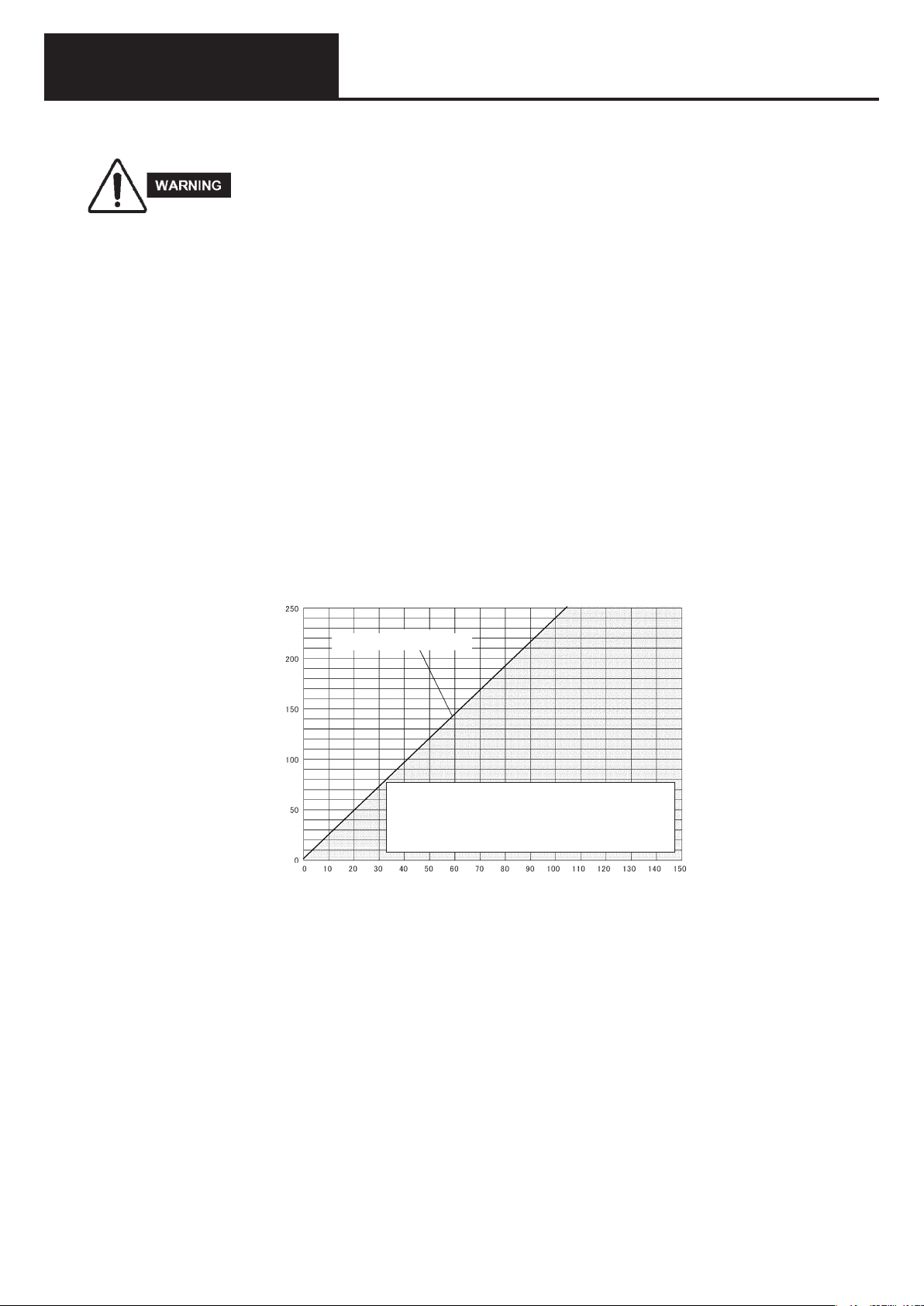
System Design
3. Refrigerant piping design
(7) Checking the density limit
The refrigerant (R410A) used in a Multi-unit air conditioning installation is in itself a safe refrigerant that
is neither flammable nor poisonous, but just in case a leak in a small room should occur, steps need to
be taken to prevent gas from exceeding the permissible concentration and causing asphyxiation. The
Japan Refrigeration and Air Conditioning Association have stipulated a threshold concentration for
refrigerants in its publication “Guidelines for Ensuring Safety in the Event of a Refrigerant Leak from a
Multi-Unit Air Conditioning System” (JRA GL-13:2010).
Apart from the lowest level underground, the threshold concentration for the charge in a system has
been set to
total refrigerant/living space capacity ≤ 0.42 kg/m3 (R410A models).
If this condition is not met, the system must either be equipped with two of the countermeasures (alarm,
ventilation or safety shut-off valve) or be redesigned.
Please note, when the system is in the lowest level underground, depending on the type of refrigerant,
the threshold concentration and number of countermeasures required may vary.
For further details, either refer to the technical document JRA-GL-13 or consult with your dealer.
Threshold concentration
)
3
Living Space (m
If the concentration of the refrigerant is within this
range, the system must either be equipped with two
of the countermeasures (alarm, ventilation or safety
shut-off valve) or be redesigned.
Total Refrigerant Charge (kg) of a Multi-Unit Package Air Conditioning System
Fig. 1 Permissible Refrigerant Charge for Specific Systems and their Required Countermeasures
(R410A Refrigerant)
<Not Including Lowest Level Underground>
D-18
Page 72
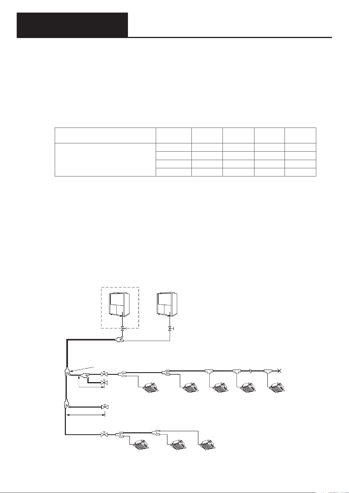
System Design
3. Refrigerant piping design
(8) Future system expansion <for W Multi Models>
(1) Conditions for adding indoor units
1) Up to 24 indoor units can be connected to an outdoor unit. (Up to two W Multi outdoor units can be
installed for up to 48 indoor units.)
2) Usable indoor unit capacity ranges are:
Minimum: 50% of the minimum capacity of the outdoor units
Maximum: 130% of the total capacity of the outdoor units
(2) Outdoor unit connection conditions (during initial installation, be sure to select piping sizes that will
support the total horsepower after expansion).
The following table shows the possible combination for future expansion based on the pipe (main pipe)
size.
Outdoor unit planned for current installation
Outdoor unit considered for expansion
(up to two units)
45.0 kW Type —
56.0 kW Type —
71.0 kW Type —
85.0 kW Type — —
45.0 kW
Type
1) Outdoor units other than those indicated above cannot be used for expansion. (Doing so may result
in a failure.)
2) During initial system installation, be sure to consider the requirements for indoor unit piping after
expansion.
(3) Select piping sizes according to requirements after expansion. [Refer to section 2, “System Piping.”]
(4) If future system expansion is anticipated, install ball valves (sold separately) at the outdoor and indoor
unit sides of the branch pipe. (Figure 1)
1) To prevent oil from being drawn inside, slope piping opposite to flow direction.
2) Locate ball valves as close as possible to the main piping (within 40 cm).
3) If the diameter of the ball valve is smaller than the main piping, install a reducer at the valve.
4) Locate the equipment where it will be easy to operate and inspect in the future.
5) Ball valves for expansion should be installed with their service ports facing the future units they will
serve.
56.0 kW
Type
71.0 kW
Type
85.0 kW
Type
—
—
Additional outdoor unit (expansion)
First branch
For
40 cm or less
40 cm or less
expansion
For expansion
For expansion
Figure 1
D-19
Page 73
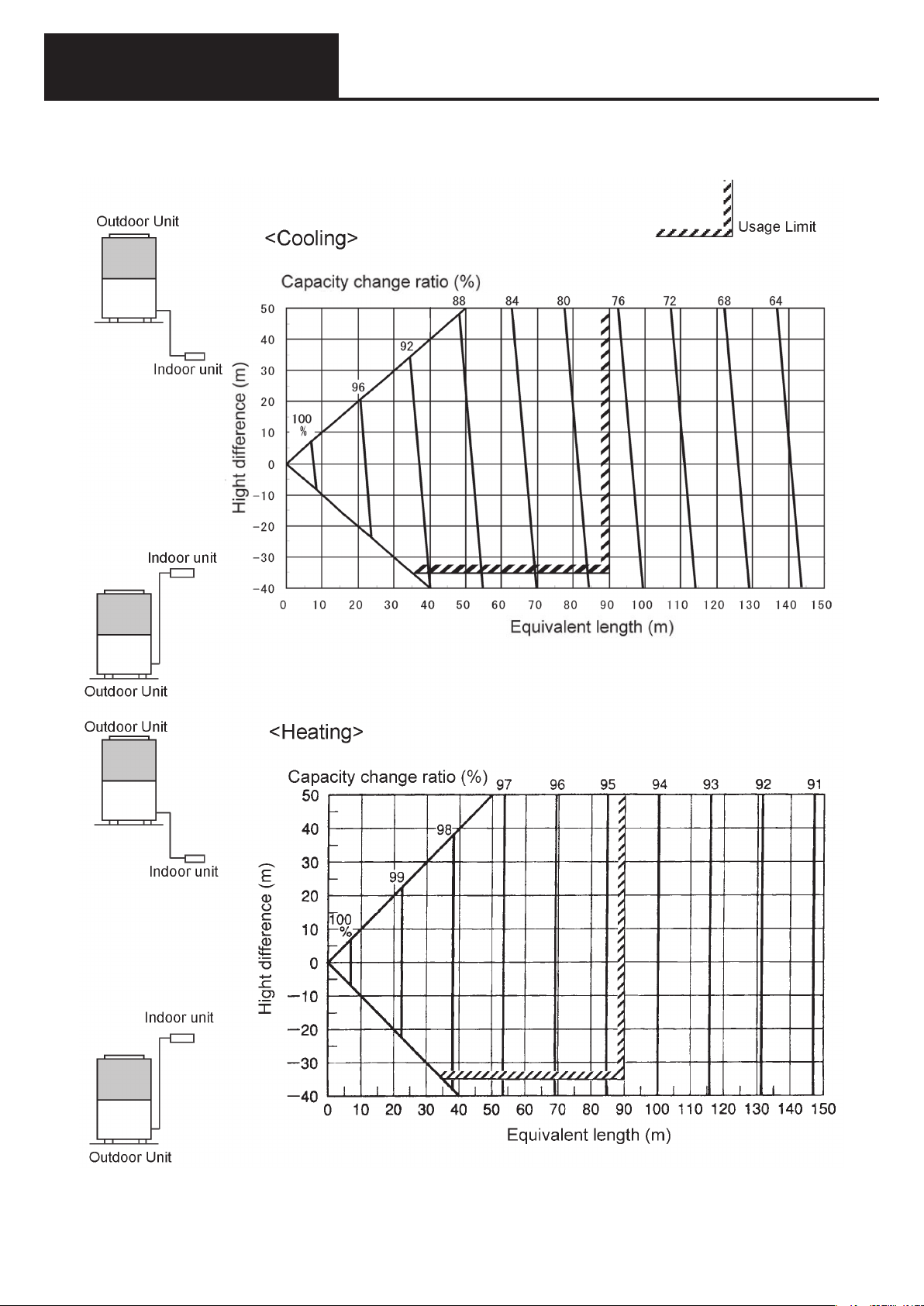
System Design
For 2WAY Multi (45.0 ~ 85.0 kW Type)
Refrigerant piping length: 90m (equivalent length) or less
4. Effect of refrigerant pipe length on performance
D-20
Page 74
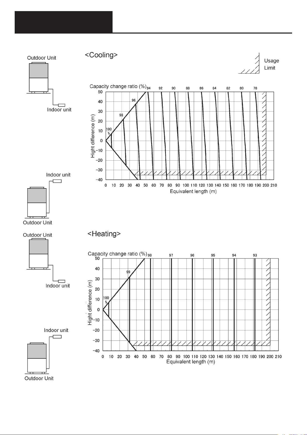
System Design
Refrigerant piping length: Over 90m (equivalent length)
4. Effect of refrigerant pipe length
on performance
D-21
Page 75
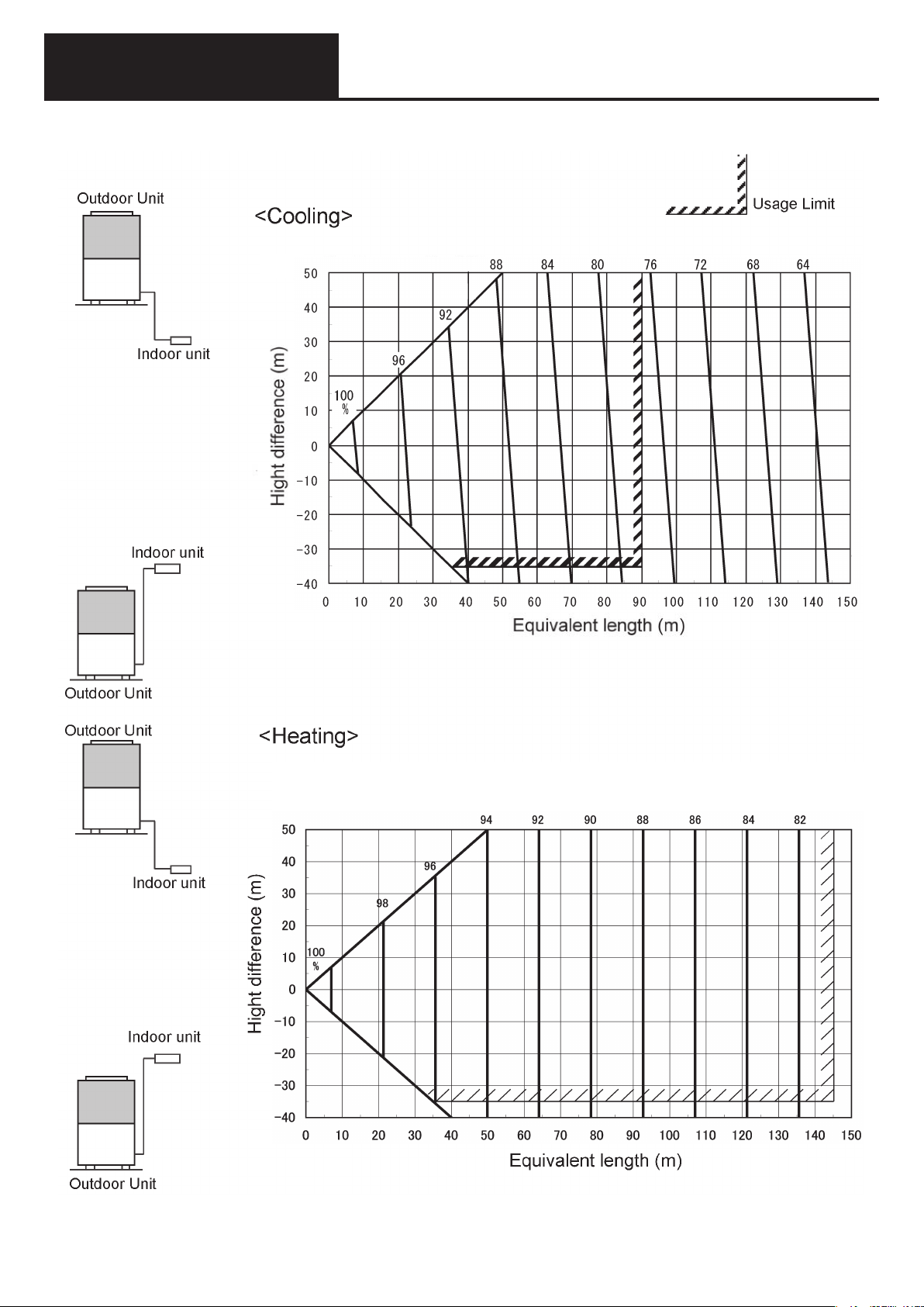
System Design
For 3WAY Multi
Refrigerant piping length: 90m (equivalent length) or less
Capacity change ratio (%)
4. Effect of refrigerant pipe length
on performance
Capacity change ratio (%)
D-22
Page 76
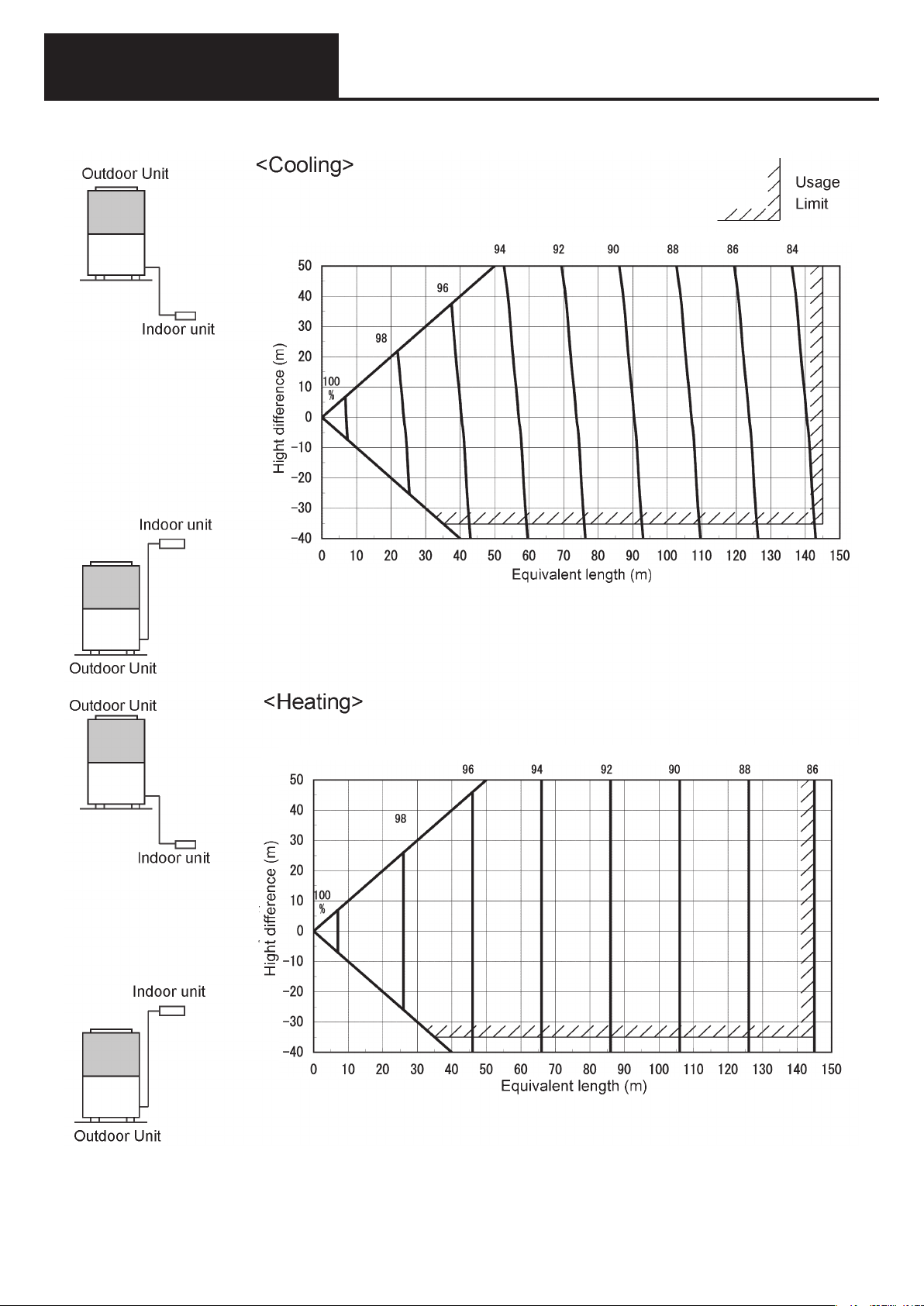
System Design
Refrigerant piping length: Over 90m (equivalent length)
Capacity change ratio (%)
4. Effect of refrigerant pipe length
on performance
Capacity change ratio (%)
D-23
Page 77
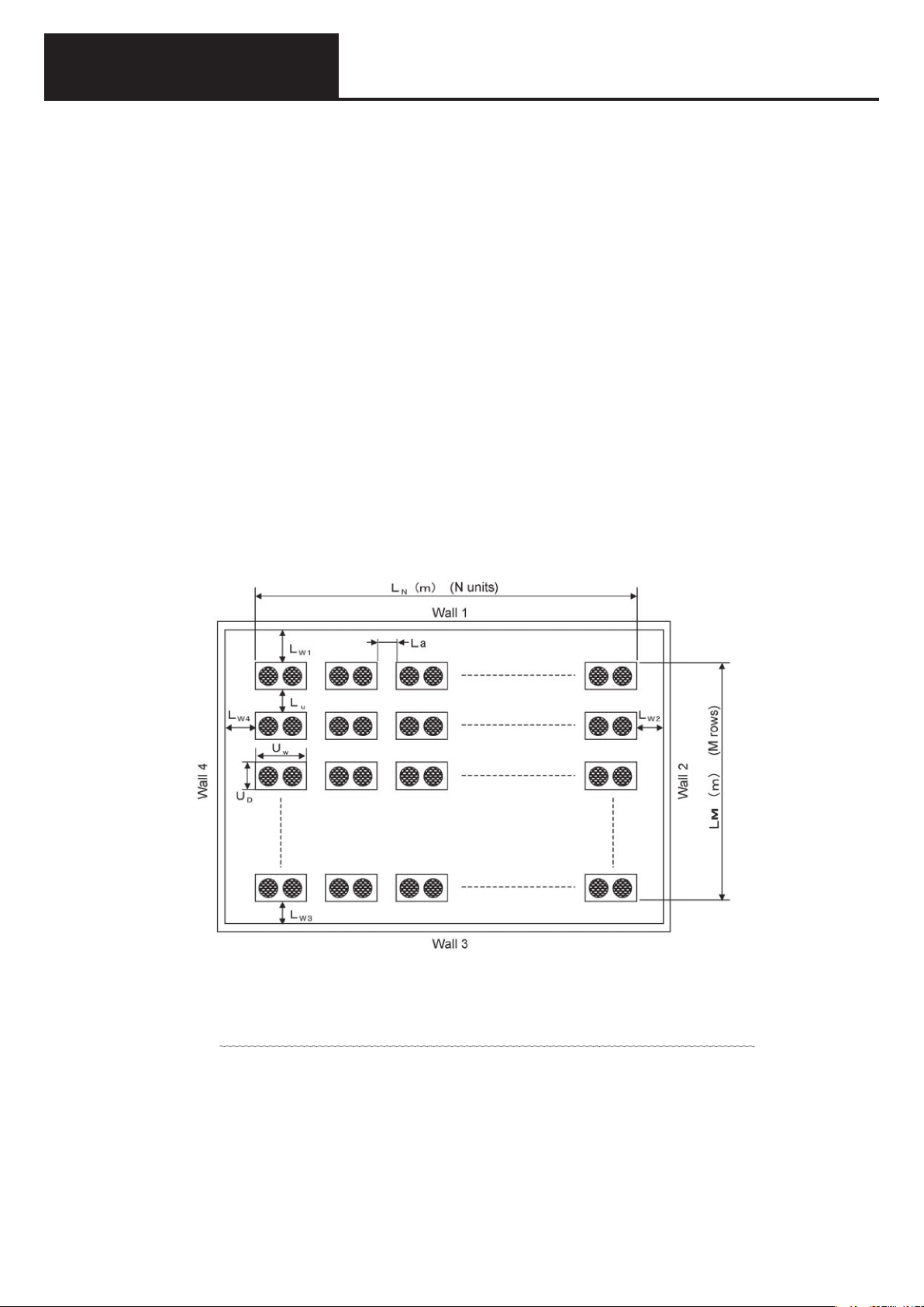
System Design
5. Outdoor unit positioning requirements
(1) Combined installation criteria
If several outdoor units are installed on, for example, the roof of a building, the space required for normal
operating airflow may be insufficient, causing exhaust air from one outdoor unit to be sucked into another,
creating a kind of airflow short circuit. This can cause an increase in the effective ambient air temperature,
impeding cooling capability or even forcing emergency shutdown.
Therefore, when installing multiple GHP units, follow the instruction criteria below to ensure sufficient airflow.
Compared with cooling, the effect on heating is slight, so there should be no problems if the installation
criteria for cooling are satisfied.
Note: In unusual installation circumstances, give these criteria appropriate consideration when making
installation decisions.
(1) Scope of applicability of criteria
These criteria apply to installations in either of the following situations:
• When eight or more outdoor units are installed in combination
• When seven or fewer outdoor units are installed where walls are present that may impede air circulation
(2) Conditions for combined installation
To ensure adequate airflow, the following conditions must be met in combined installations:
• Adequate spacing must be provided between each outdoor unit and between rows of units.
• Adequate clearance for airflow from the surroundings must be provided for the combined outdoor
units.
(3) Parameters for combined installations
[1] Rows of outdoor units
La = Average distance between outdoor units (m)
• When the distance between outdoor units is unequal, La is the average.
• Locate no more than three outdoor units near each other.
• If there are six or more units in a row, leave a one-meter gap every three units.
Lu = distance between rows (m)
• All distances Lu should be equal.
LN = Row length (m)
LM = Depth of outside of installation (m)
LW = Distance from wall to nearest outdoor unit (m)
• If no wall, LW = 6.
UW = Width of outdoor unit (m)
UD = Depth of outdoor unit (m)
D-24
Page 78
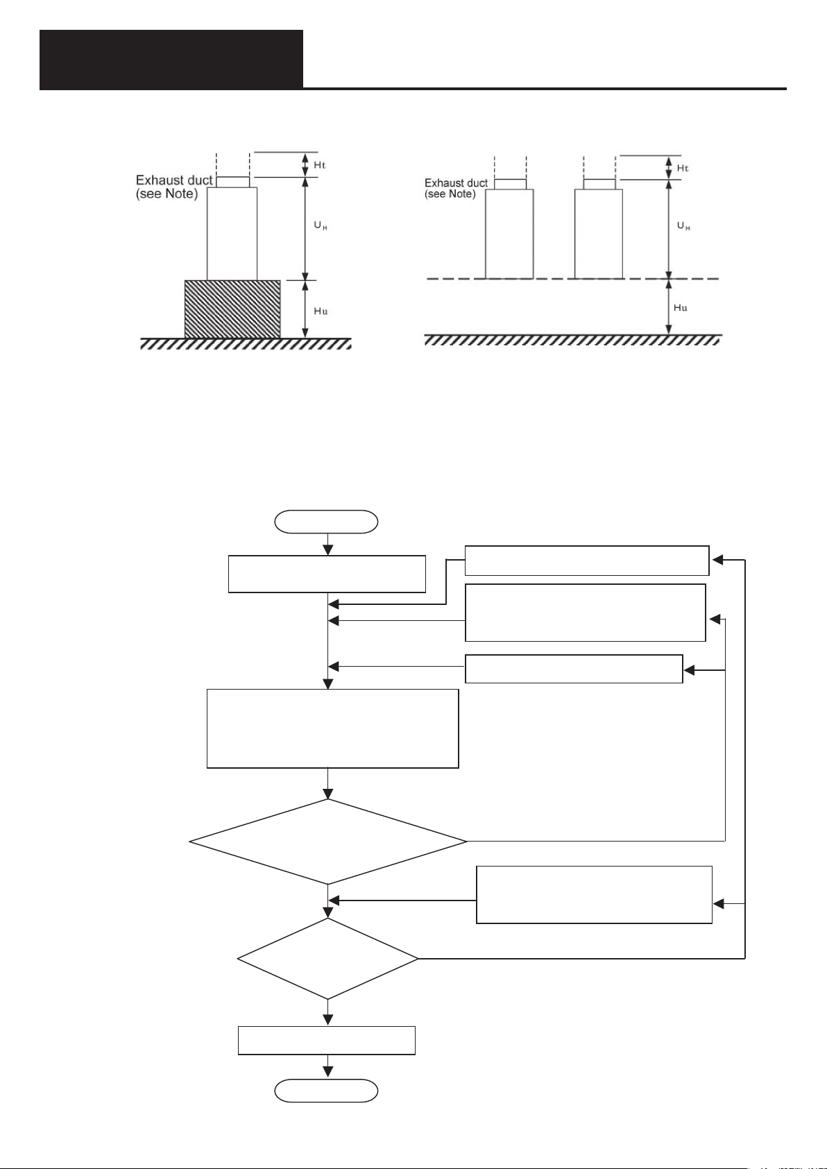
System Design
a
R
5. Outdoor unit positioning requirements
• Outdoor unit installation methods
Concrete pad mounting Catwalk mounting
UH = Height of outdoor unit (m)
Ht = Air exhaust duct height (m)
Hu: Height of pad or catwalk (m) H = Hu + Ht (m)
Note: When an air exhaust duct is used, take steps to prevent engine exhaust gas from entering the
heat exchanger, such as extending the exhaust pipe to the same height as the air exhaust duct.
(4) Outdoor unit array design flowchart
Start
Determine actual installation capacity
(horsepower)
Provisional configuration
•
Refer to
(5)? [1]
Refer to
(5)? [2]
Preliminarily determine average distance L
between outdoor units
•
Calculate Lu, the distance between rows
Will you calculate row length L
and external installation dimension LM?
Yes
•
Increase distance from wall to outdoor unit
•
Increase mounting height
•
Install an exhaust duct
•
Change to catwalk mounting
•
Change number of units per row, or L
N
No
•
Increase wall opening size
•
Decrease wall height
•
Increase distance from wall to outdoor unit
a
Refer to
(5)? [3]
Is ambient airflow adequate?
No
Yes
efer to (6)
Correct cooling capacity
END
D-25
Page 79
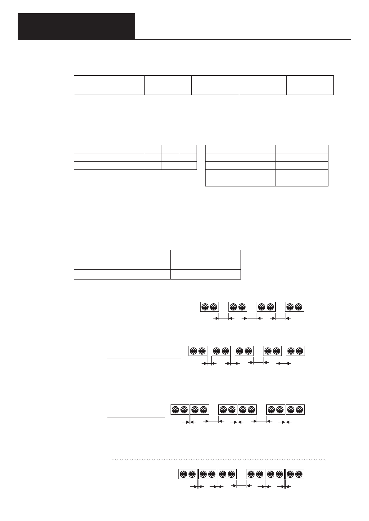
System Design
s)
(1m)
s)
L
L L
s)
L
2
L
2
s)
(5) Outdoor unit array design considerations
[1] Provisional design (calculation of distance between units and rows)
Consider the provisional arrangement of different model types (Table 1)
Table 1
Model Type 16 HP 20 HP 25 HP 30 HP
Outdoor unit type 45.0 kW 56.0 kW 71.0 kW 85.0 kW
1) Calculation parameters (Table 2)
Outdoor unit external dimensions Outdoor unit airflow (Table 3)
UH = Height (m) Q = Fan flow rate (m3/min)
UW = Width (m)
UD = Depth (m)
Table 2 Table 3
Model Type UH UW UD Model Type Q
16, 20 and 25 HP 2.27 1.65 1.0 16 HP 370
30HP 2.27 2.03 1.0 20 HP 360
Note: For installation parameters, see (3), “Combined installation parameters.”
2) Calculate the average distance between units (La) and the distance between rows (Lu)
Here, a provisional value for La is selected from Table 4, and Lu is then calculated.
If La is large, Lu is small, and if La is small, Lu is large..
Note: The minimum maintenance space between units and rows shown in Table 4 must
bemaintained.
Table 4
Model Type 16, 20, 25 and 30 HP
Minimum spacing between units 0.1m
Minimum spacing between rows 0.95m
5. Outdoor unit positioning requirements
25 HP 400
30 HP 460
a) Provisional determination of La [Pattern 1] Independent arrangement
Rows can be arranged in three patterns, as follows. (continuous groups of up to three units)
La is determined respectively as follows.
…
For L 0.35m
La = L
L L L
(n unit
For L < 0.35m
Provide a space of at least 0.35m every three units. (L2 0.35)
La is the average distance between units.
L+L+L2+L+ · · · · + · · · ·
La=
N-1
L1 = Minimum distance between continuously
L
2
[Pattern 2] Paired units
…
(n unit
spaced units (see Table 4)
L2 = Provide a larger space (at least 0.35m) between each pair. (L2 0.35)
La is the average distance between units.
L1+L2+L1+L2+L1· · · ·
La=
N-1
L
1
L1 = Minimum distance between continuously
L
1
L
1
[Pattern 3] 3-unit clusters
…
(n unit
spaced units (see Table 4)
L2 = Provide larger space (at least 0.35m) between each 3-unit cluster. (L2 0.35)
If there are six or more units in a row, leave a one-meter gap every three units.
La is the average distance between units.
L1+L1+L2+L1+L1· · · ·
La=
N-1
L
L
1
1
L
L
2
L
1
1
…
(n unit
D-26
Page 80
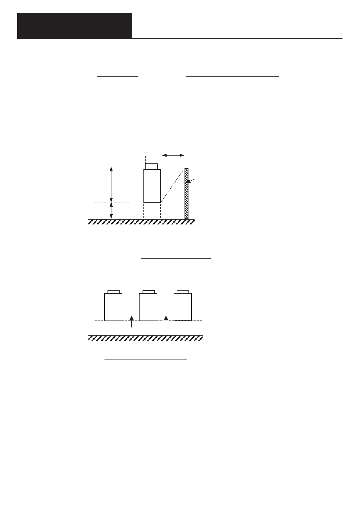
System Design
L
5. Outdoor unit positioning requirements
b) Calculating L
U
Calculating necessary passage area S (m2)
(calculated on the basis that the airflow between units or rows is a standard 1.5 m/s)
Qm×N×(M-1)
S=
90
Qm=
Total outdoor unit airflow (m3/min)
No. of outdoor units
Calculation of actual passage area Sa (m2)
• For installations on concrete pads
Sa = [(UH + H) × La + 0.25La2] × 2(N - 1)
• For installations on catwalks
Sa = [(UH + H) × La + 0.25La2] × 2(N - 1) + 2N × UW × HU + 2M × UD × H
In this example, airflow to the catwalk is obstructed by a wall
W
In the diagram at the left, if LW ≤ UH + HU, airflow
to the catwalk is obstructed. Airflow from the
wall side should be assumed to be zero.
In the above formula, the second parameter
U
H
Wall
is obtained from the area of air inflow from
Wall1 and Wall3 sides, and the third parameter
is obtained from the air inflow area from the
H
U
Catwalk
Wall2 and Wall4 sides.
When LW > UH + HU, obtain Sa from the above
formulae.
U
Calculation of Lu, the distance between rows
For installations on concrete pads
- (UH+H) + √(UH+H)2+(S-Sa) / [2(M-1)]
Lu=
0.5
For installations on catwalks
Catwalk Airflow
(S-Sa)+(UW × UD × N × (M-1)
Lu=
[UW × N+La × (N-1)] × (M-1)
-U
D
As shown in the diagram at the left, obtain Lu
from the formula below by considering airflow
from the bottom of the unit. However, if LW ≤
UH + HU, Lu is the same as for concrete pads.
D-27
Page 81
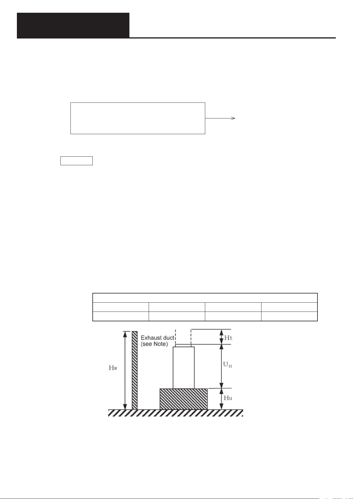
System Design
5. Outdoor unit positioning requirements
[2] Determining row length LN and depth of outside of installation L
1) Calculating row length L
Obtain the row length from the following formula. (Refer to paragraph (5)-[1] for descriptions of
parameters.)
LN=UW×N+La×(N-1)
2) Calculating depth of outside of installation L
LM=UD×M+Lu×(M-1)
Note: If LN and LM are unsuitable, perform one or more of the following, and recalculate.
• Change the units per row or La, and rearrange
• Increase the height of pads or catwalks
• Install exhaust ducts
• Change from pads to catwalk mounts
[3] Providing area for air inflow
Procedure:
↓
1) Calculate necessary inflow area Sr
2) Calculate the area of air inflow from surroundings
a) Calculate effective inflow height Hwe
b) Calculate effective inflow length Le
c) Calculate effective inflow area Se (= Hwe × Le)
3) Determine inflow area
N
M
1. Walls the permit air passage (incl. no wall)
2. Walls that block air passage
M
Return to paragraph (5) -[1]
1) Calculate necessary inflow area Sr
Obtain the necessary air inflow area Sr (m2) to outdoor units in a combined installation from the
following formula.
(Sr is the minimum area necessary to avoid degrading system performance.)
Sr= (US1×NT1)
where Sr = necessary inflow area (m2)
US1 = necessary inflow area per outdoor unit (m2) (see table below)
NT1 = total number of outdoor units installed
Necessary air inflow are per outdoor unit (US1) [m2]
16 HP 20 HP 25 HP 30 HP
13.3 13.3 13.3 15.3
Note: When an air exhaust duct is used, take steps to prevent engine exhaust gas from entering
the heat exchanger, such as extending the exhaust pipe to the same height as the air
exhaust duct.
D-28
Page 82
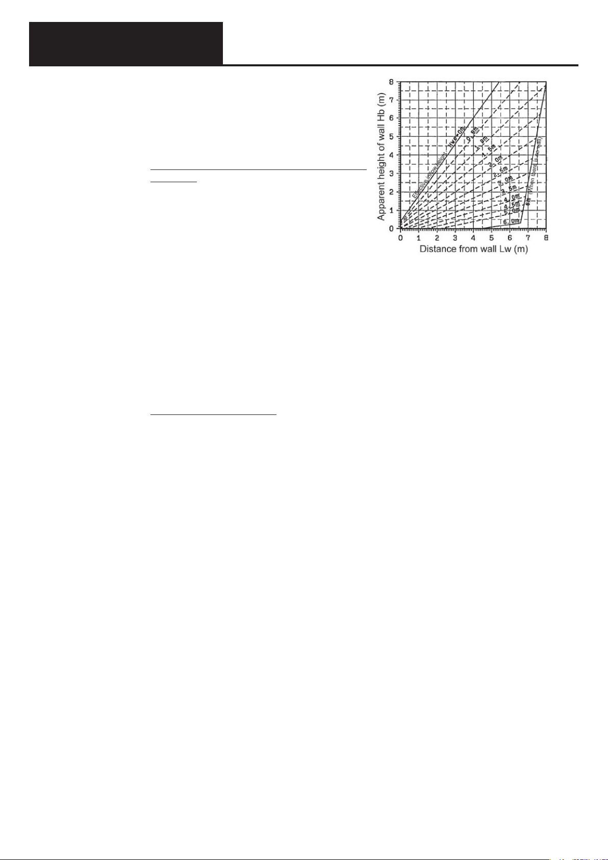
System Design
2) Calculate the area of air inflow from surroundings
Calculate the effective inflow area, considering the effect
of surrounding walls.
a) Calculate effective inflow height Hwe
The calculation method depends on the type of wall.
The two types to consider are louvers, which allow
air to pass, and sound barrier walls, which do not.
i). Walls the permit air passage (including the case
of no wall)
• Use the following formula to calculate the
height of inflow,
Ha1 to Ha4 (m) for each wall.
Ha = LW + Hu + 1.5Ht + U
where
Ha = inflow height (m)
LW = Distance from wall to nearest outdoor unit (m)
• Calculate effective inflow height Hwe (m) for each wall. Depending upon wall height and
inflow height Ha, apply one of the following formulae.
For Hw ≥ Ha, Hwe =(Ha – (HU + HH + Ht)) × Xw + (HU + HH + Ht) × Xw × 2
For Hw < Ha, Hwe =(Ha – Hw + [Hw – (HU + HH + Ht)] × Xw + (HU + HH + Ht) × Xw × 2
where Hw = Wall height (m)
• The wall height below the exhaust part (HU + HH + Ht) has twice the weighting of other
parts (inflow wind speed is doubled from 0.5 to 1 m/s).
• When there is no wall, Hwe = Ha.
ii). Walls that block air passage
• Use the following formula to calculate apparent heights Hb1 to Hb4 (m) for each wall.
Hb = Hw – HU – 1.5Ht
where Hb = Apparent height (m) of wall
• For each wall, use the diagram at the right to obtain the effective inflow heights Hwe1 to
Hwe4 (m) for each wall.
b) Calculate effective inflow length Le
From the effective inflow height Hwe calculated for each wall, calculate effective inflow lengths Le1 to Le4.
•
Calculate the effective distance from each boundary surface (wall) to the nearest unit, Lwei (m).
With no wall: Lwei = 6
If Lwi ≥ 6m, then Lwei = 6
If Lwi < 6m, then Lwei = Lwei
• Calculate effective inflow lengths Le1 to Le4 (m) for each wall.
Le1=LN+Lwe4+Lwe
Le2=LM+Lwe3+Lwe
Le3=Le
Le4=Le
c) Calculate effective inflow area
From effective inflow heights Hwe1 to Hwe4 and lengths Le1 to Le4, calculate the effective
inflow area for each wall.
i) Calculate effective inflow area Se1 to Se4 (m) for each wall.
Se1=Hwe1×Le
Se2=Hwe2×Le
Se3=Hwe3×Le
Se4=Hwe4×Le
ii) Calculate the overall effective inflow area, Set (m2).
Set=Se1+Se2+Se3+Se
iii) Calculate the areas of adjoining surfaces.
Se12=Se1+Se
Se23=Se2+Se
Se34=Se3+Se
Se41=Se4+Se
1
2
5. Outdoor unit positioning requirements
H
However, when there is no wall, LW = 6.
(Refer to item (5) -[1]-1) for details of UH.)
Xw = Wall opening fraction
Hw = Wall height (m)
2
1
1
2
3
4
4
2
3
4
1
D-29
Page 83
System Design
3) Judge the inflow area
From the required inflow area calculated in 1), and the effective inflow area calculated in 2)-C),
satisfy the following two conditions.
1) Overall effective inflow area (Set) must be greater than required inflow area Sr.
2) In an array with three or more rows, the smallest value of inflow area of two adjoining walls
(Se12, Se23, Se34 or Se41) must be greater than 25% of Sr: Min(Se12, Se23, Se34 or Se41) ≥
0.25 × Sr
If these conditions are not satisfied, apply the following measures, and recalculate.
• Increase mounting height
• Install exhaust ducts
• Change from pads to catwalk mounts
• Increase wall opening size
• Lower the height of walls
• Increase the distance from walls to units
(6) Correction of cooling capability
By meeting these criteria, the temperature of the intake air in this combined installation is expected
to rise by 3ºC during cooling.
Obtain the reduction in cooling capability for each unit from the characteristics for that model type.
5. Outdoor unit positioning requirements
Return to paragraph (5) -[1]
Return to paragraph (5)-[3]-2)
D-30
Page 84
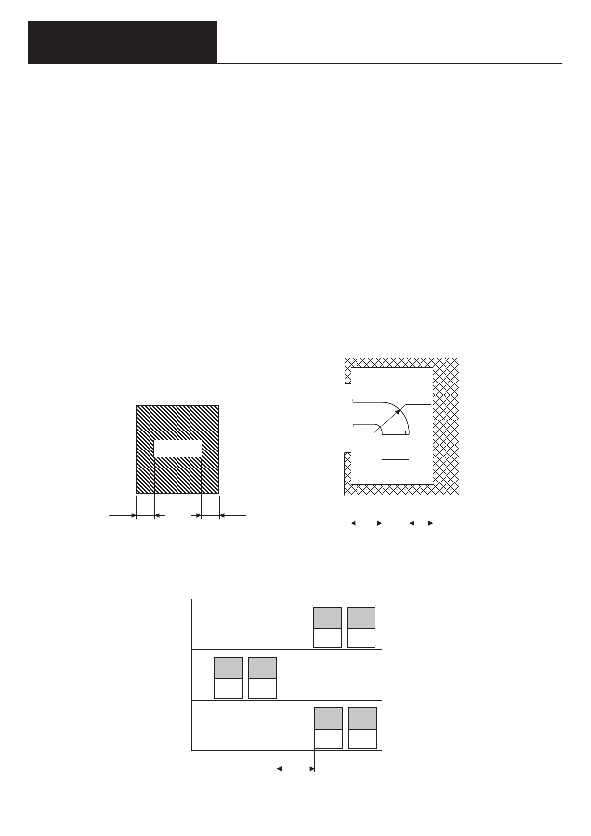
System Design
Figure 1 Figure 2
t
A
A
A
A
0
)
Figure 3.
F
F
F
A
r
t
5. Outdoor unit positioning requirements
(2) Verandah installation criteria
If outdoor units are installed on a verandah where they are surrounded (by walls and ceiling) on five sides,
the design layout must take into account short-circuit airflow and maintenance space requirements. Evaluate
the installation on each floor of a building in the same way.
(1) Design points
1) Do not allow the exhaust air from an outdoor unit to recirculate, as this would seriously degrade
system performance.
2) Do not install a gallery on the exhaust outlet. (Installing a gallery reduces airflow by over 10%.)
3) Create an environment in which exhaust air from the outdoor unit will not cause any problems.
4) Comply with local regulations regarding operating noise from outdoor units.
5) Distance to the nearest building should be at least 10m.
6) Design external air conditions are based on ambient temperature of 35ºCDB or less.
7) Make certain to provide adequate maintenance space.
(2) Necessary inflow area
1) For an installation like that of Figure 1, the shaded area indicates the inflow area.
2) The necessary inflow area for one 13- to 25-HP outdoor unit is 12.7m2, so the shaded area is the
necessary inflow area
(3) Maintenance space
Provide maintenance space with the dimensions in Figures 1 and 2.
t least
R1000
Exhaust outle
t least 100
(Refrigerant pipe side
t least 350
At least 350
t least 1000
(Front)
(4) Installations on each story
When installing on multiple stories, a horizontal separation of 5m should be provided as shown in Figure
3 to prevent intake of exhaust air from outdoor units on the floor below.
Outdoor unit
Outdoor unit
3
2
Outdoo
D-31
1
uni
t least 5 m
Page 85
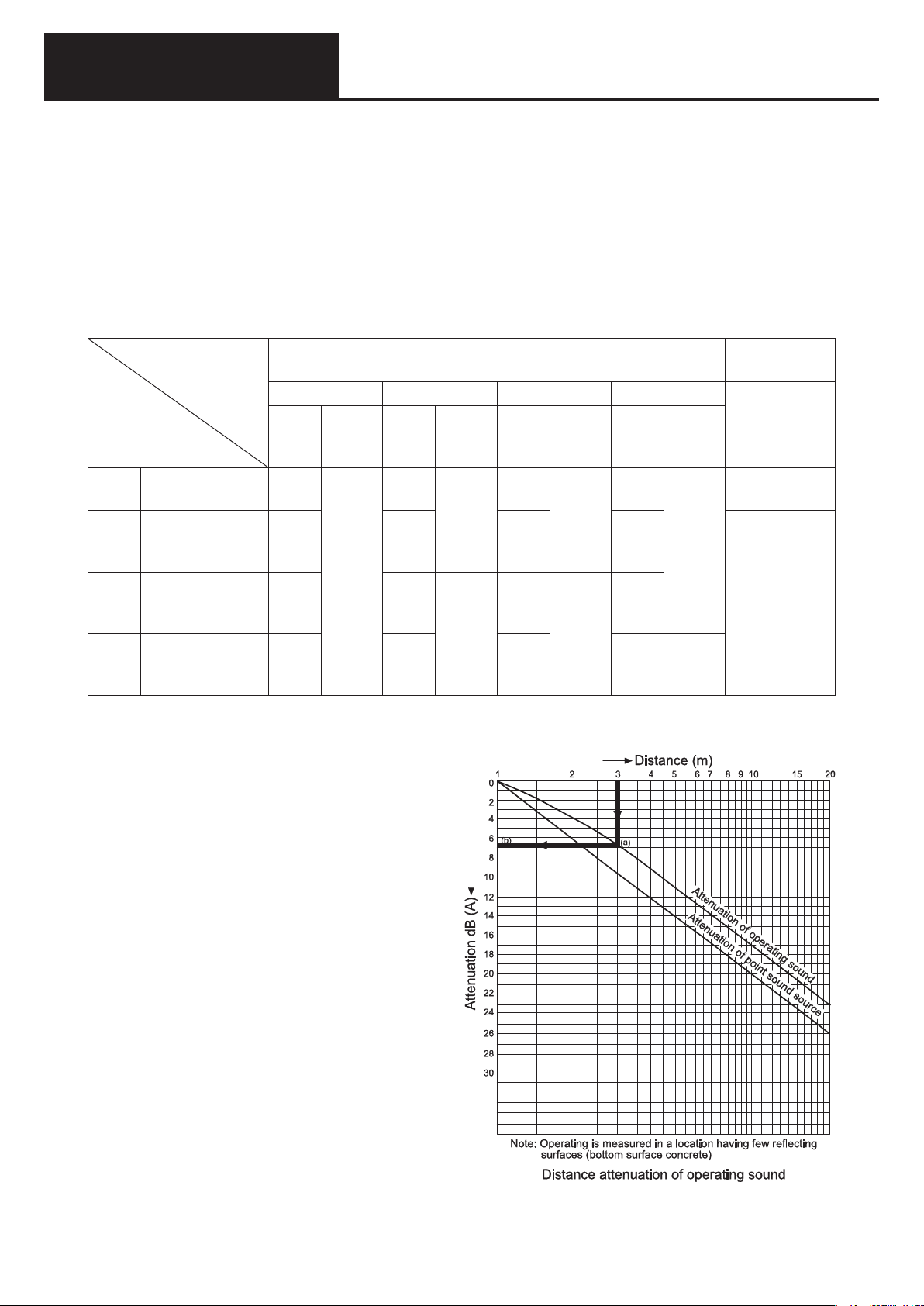
System Design
6. Sound-proofing measures
(1) Installation location and sound-proofing measures
If no suitable installation location is available and it is necessary to install in a confined location where there
are houses, offices or other buildings nearby, it may be necessary to provide sound barrier walls, sound
absorption chambers or other secondary sound-proofing measures.
Secondary sound-proofing measure include:
• Attenuation over distance
• Sound-proofing with noise barriers
• Sound-proofing using sound absorbing chambers
• Sound-proofing by vibration isolation (anti-vibration pads, flexible couplings, etc.)
The following criteria are from Tokyo Pollution Prevention Regulations.
Criteria for everyday sound levels
Area type
Type 1
Type 2
Type 3
Type 4
Residential and
school areas, etc.
Residential and
undesignated
areas
Commercial,
light industrial,
industrial areas
Shopping areas
and specially
designated areas
Condition
Morning Daytime Evening Night
Sound
level
(phon)
40
45 50 45 45
55 60
60 70 60 55
Time
6 AM to
8 AM
Ordinary standards
Sound
level
(phon)
45
Time
8 AM to
7 PM
8 AM to
8 PM
Sound
level
(phon)
40
55
Time
7 PM to
11 PM
8 PM to
11 PM
Sound
level
(phon)
40
50
Time
11 PM
to
6 AM
standards
Near schools
and hospitals
(approx. 50m)
Same as at left
At least 5 phon
lower than at
Special
left
(2) Attenuation of sound over distance
The figure at the right shows sound attenuation
over distance. (Figure 1)
Operating sound is measured 1m from its source.
Example. For a type 280 outdoor unit, the sound
level in the 50-Hz range at 3m distance
is specified as 56 dB(A). In Figure 1,
follow the 3m distance line downwards
to where it crosses the slope (a), and
then horizontally to point (b) at the left
to find the attenuation of 6.8 dB(A).
Therefore, 56 – 6.8 = 49.2 dB(A)
D-32
Page 86
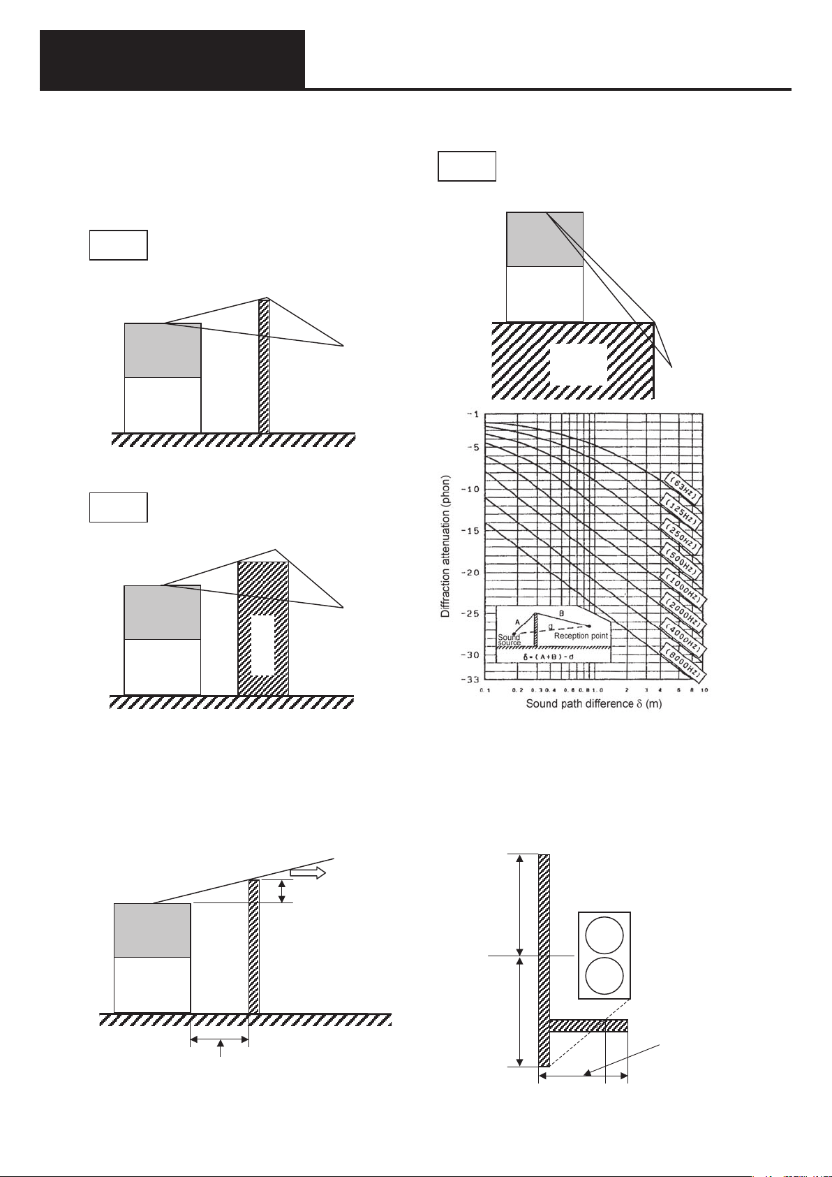
System Design
A
A
O
A
Figure 2. Diffraction attenuation
A
O
Figure 3. Sound barrier
6. Sound-proofing measures
(3) Sound attenuation by a noise barrier
Sound attenuation of an indoor unit at a reception point behind a noise barrier or building depends on the
frequency and path length difference.
Ex. 2
δ = path length difference
δ = (A+B) – d
Ex. 1
Outdoor unit
utdoor unit
Ex. 3
Outdoor unit
B
d
Sound barrier
?
Reception point
B
d
?
Reception point
Building
d
B
?
Reception point
Building
(Be certain to preserve the required space for air intake and exhaust, service and maintenance.)
The barrier should be sufficiently higher than the top of the outdoor unit. (Figure 3)
(However, not more than 1m higher.)
The width of the barrier should be at least several times the height, on both sides of the center. Where
this is not possible, the barrier should bend around the unit as shown in Figure 4.
The barrier should be located as close as possible to the outdoor unit (sound source). (Figure 3)
Effective area
utdoor unit
B
As close as possible (while maintaining minimum clearances
required for intake, exhaust and servicing of each unit)
1 m or less
Sound barrier
At least several
times the barrier
height
?
Reception point
At least several
times the barrier
height
Outdoor unit
Sound barrier
Figure 4. Sound barrier
When adjoining
barriers, longer
than this line.
D-33
Page 87
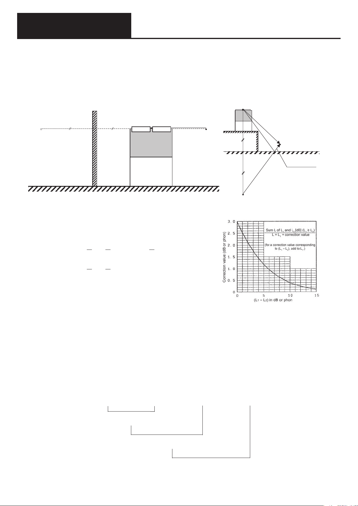
System Design
65 64 63 60
68.8 + 0.5 = 69.3 dB
Figure 5. Combined sound correction values
V
Sound source A
(g
)
6. Sound-proofing measures
(4) Additional sound from reflections
Operating sound from outdoor units reflects from the walls of building and ground surfaces. These
reflections are received at the reception point, increasing the sound level of the system.
The sound received at the reception point is the sum of the sound propagated directly from the source
plus reflected sound.
The reflected sound level is obtained by establishing a virtual sound source (A'), and estimating the
sound level at B from A' (subtract the distance attenuation over the path A'-B). See the next paragraph
on combining sounds for a description of how to add direct and reflected sounds.
irtual sound source A'
Sound barrier
Figure 6. Adding reflected sound (wall surface)
(5) Combining sounds
For multiple outdoor units, the sound level at the reception
A
Outdoor Unit
B
Reception point
Reception point B
Reflected sound
(reflection surface)
’
Reception point B
Figure 7. Adding reflected sound
round surface
point is determined by combining the sounds from each unit.
The combined sound from n units L1, L2, …Ln is expressed
by the following formula.
If L = the combined sound level,
L = 10 log10 (10
For example, adding 61 phones and 62 phones gives
L = 10 log10 (10
L1
10
61
10
+ 10
+ 10
L2
10
+ · · · · · · + 10
62
10
) = 64.5 dB
L3
10
)
This for of expression is applicable for any value of n.
Although sound level can be calculated this way, for simplicity,
we have prepared graphs to use instead.
<Calculation Example 1>
Calculate the combined sound level of L1 = 62 [dB] and L2 = 61 [dB]. L1 – L2 = 62 – 61 = 1 [dB], the correction
value from Figure 5 is 2.5 [dB], and 62 + 2.5 = 64.5 [dB], so the combined sound level is 64.5 [dB].
<Calculation Example 2>
To combine sound levels of 60, 64, 63 and 65 dB, first sort the values in order of magnitude.
65, 64, 63 and 60 dB
Then combine 65 and 64 dB to obtain the difference, 65 – 64 = 1 dB, which has a correction value of 2.5
dB, and 65 + 2.5 = 67.5 dB.
Next, combine 67.5 and 63 dB for a difference of 4.5 dB, for which the correction value is 1.3 dB, and 67.5
+ 1.3 = 68.8 dB.
In the same way, combine 68.8 and 60 dB for level difference of 8.8 dB, for which the correction value is
0.5 dB.
And finally, 68.8 + 0.5 = 69.3 dB, which is the combined level of the four sounds.
Difference = 1
Correction value = 2.5
65+2.5=67.5
Difference = 4.5
Correction value = 1.3
67.5+1.3=68.8
Difference = 8.8
Correction value = 0.5
D-34
Page 88
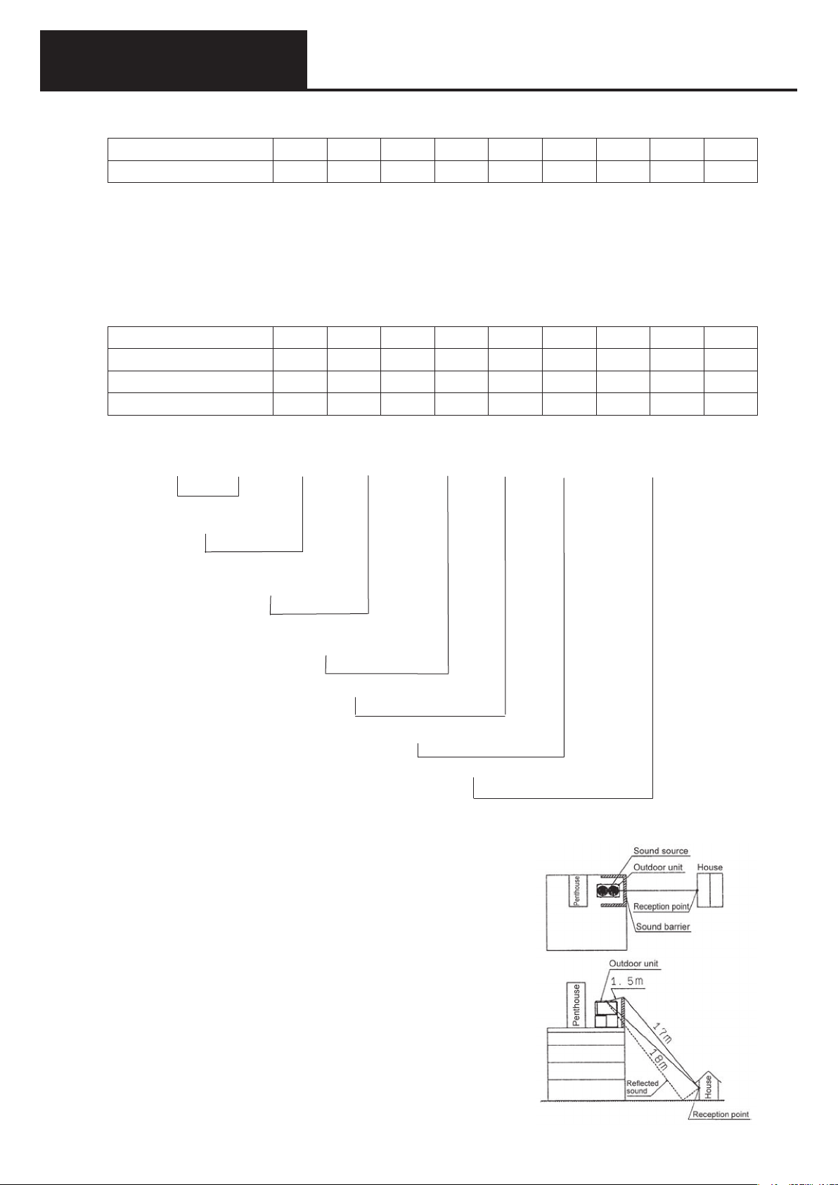
System Design
56 56 53 50.5 50 46 43 40.5
60.95
6. Sound-proofing measures
(6) Converting from octave band levels to overall A weighting
Table 1. Correction factor for converting from octave bands to A weighting
Octave band Hz 63 125 250 500 1000 2000 4000 8000
Conversion factor dB –26 –16 –9 –3 0 +1 +1 –1
Using the above table, the A weighting is obtained by adjusting the calculated value for each band by its
conversion factor. These values are then combined in order of magnitude, as shown in the following example,
to obtain the overall A weighting.
<Calculation example>
The octave band levels (dB) are obtained from the frequency analysis table (the operating sound level at
the center frequency of each octave band). These values are corrected with the A weighting correction
factor to obtain the A weighting. The following calculation determines the operating sound level.
Octave band Hz 63 125 250 500 1000 2000 4000 8000
Octave band level dB 69 66 62 59 56 49.5 45 41.5
Conversion correction dB –26 –16 –9 –3 0 +1 +1 –1
A weighting dB(A) 43 50 53 56 56 50.5 46 40.5
These A-weighting values are combined one-by-one in order of magnitude (in the same away as combining
different operating sounds).
Difference
= 0
56+3.0
=59
Difference = 6
59+0.95
=59.95
Difference = 9.45
59.95+0.45
=60.4
Difference = 10.4
60.4+0.35=60.75
Difference = 14.75
60.75+0.1=60.85
Difference = 17.85
60.85+0.1=60.95
No further calculation necessary
The overall A weighting is thus calculated to be 60.95 dB(A).
(7) Designing sound-proofing countermeasures
<Calculation example>
In the installation drawing at the right, a scheme to suppress
operating sound at the reception point is required.
First, determine the operating sound level of the outdoor unit at
each frequency. By applying this information to Table 1, the soundproofing calculation sheet, sound attenuation and additions are
calculated for the installation.
D-35
Page 89
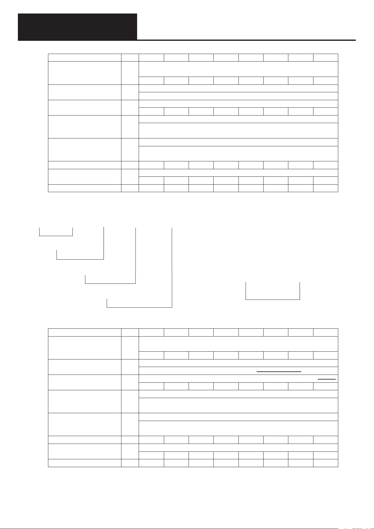
System Design
31 30.5 29 28 23.5
The overall A weighting at the reception point is
Table 1. Sound-proofing calculation sheet (filled-in example)
Frequency Hz 63 125 250 500 1000 2000 4000 8000
1) Operating sound of
outdoor unit
2) Distance attenuation dB
3) Refraction attenuation dB
4) Additional sound
from reflections (wall
surface)
5) Additional sound from
reflections (ground
surface)
6) Subtotals dB 49.5 45 39.5 34 28 18.5 11 4.5
7) Overall A-weighting
correction factors
8) A weighting dB(A) 23.5 29 30.5 31 28 19.5 12 3.5
When the calculations of Table 1 are completed, the overall A weighting can be calculated.
From the operating sound characteristics diagram in the outdoor unit
dB
69 66 62 59 56 49.5 45 41.5
From distance attenuation
From Fig. 1, attenuation of unit operating sound = -22
Fig. 2, Refraction attenuation, sound path difference δ = A + B – d = 0.5
–3.5 –5 –6.5 –9 –12 –15 –18 –21
Fig. 6, Additional sound due to reflections (wall)
dB
By calculation or the simplified method, the maximum value of the two
combined sounds is +3
Fig. 7, Addition sound due to reflection (ground surface)
dB
By calculation or the simplified method, the maximum value of the two
combined sounds is +3
dB
–26 –16 –9 –3 0 +1 +1 –1
Conversion factors for A weighting
6. Sound-proofing measures
manual
Difference = 0.5
(31 + 2.7)
33.7
Difference = 4.7
(33.7 + 1.2)
34.9
(34.9+0.8)
35.7 Difference = 5.95
Difference = 12.2 (35.95+0.95)
35.7 + 0.25 = 35.95 dB
(8) Sound-proofing calculation sheet (example)
Frequency Hz 63 125 250 500 1000 2000 4000 8000
1) Operating sound of
outdoor unit
2) Distance attenuation dB
3) Refraction attenuation dB
4) Additional sound
from reflections (wall
surface)
5) Additional sound from
reflections (ground
surface)
6) Subtotals dB
7) Overall A-weighting
correction factors
8) A weighting dB(A)
By completing the calculations in the above table, the overall A weighting at the reception point is obtained
(calculate in order from the highest sound level).
Once the overall A weighting has been calculated, combine with the ambient noise level to obtain to total
sound level at the reception point.
dB
dB
dB
dB
calculated to be 35.95 dB(A).
If the ambient noise (when the unit is not
operating) is 30.0 dB(A), the combining these
levels gives 36.9 dB(A).
35.95 30.0Difference = 6.9
=36.9
From the operating sound characteristics diagram in the outdoor unit
manual
Distance attenuation
Distance attenuation value =
Refraction attenuation, sound path difference δ = A + B – d, δ =
Additional sound due to reflections (wall)
By calculation or the simplified method, the maximum value of the two
combined sounds is +3
Fig. 7, Addition sound due to reflection (ground surface)
By calculation or the simplified method, the maximum value of the two
combined sounds is +3
–26 –16 –9 –3 0 +1 +1 –1
Conversion factors for A weighting
D-36
Page 90
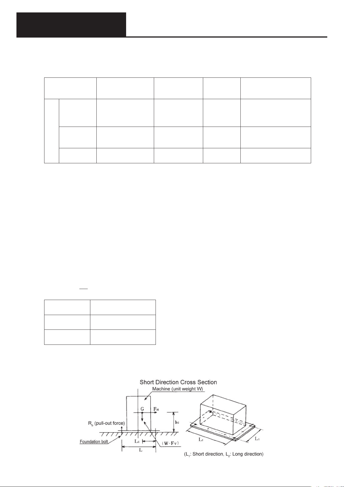
System Design
7. Center-of-gravity and earthquake resistance
(1) Earthquake resistance calculations
Several earthquake-resistance ranks are used for carrying out earthquake-resistance calculations, as
shown in the following table. Gas heat pump air conditioners are considered to be common use equipment.
• Equipment earthquake-resistance ranks
Earthquake-resistance ranks and their meanings are as follows
Maintenance of
operation
Earthquake
resistant type
Common use
Resistance
Equipment Earthquake
type
Small
equipment
Can be operated after
inspection
Can be operated after
small-scale repairs
(Note 1)
As above 0.6 G As above As above
Notes
1) Small-scale repairs are those that require up to two days to complete.
2) Mainframe strength (static), fasteners for each component (bolts, etc.)
3) Mounting bolt calculations, etc.
* The table is from “Earthquake-resistant equipment specification criteria for package air conditioners and
water chillers” published by the Japan Refrigeration and Air Conditioning Industry Association.
The above criteria are applicable to normal air conditioning equipment installed in buildings subject to
normal approval procedures under the Buildings Standard Law (e.g., less than 60m high)
Horiz. design force
(Horizontal seismic
coefficient)
1.5 G
1.0 G As above
Strength
calculation
Design target
value
Earthquake-resistance
evaluation
Strength calculation or
verification test (Note 2),
and installation earthquake-
resistance
Installation earthquake-
resistance evaluation (Note 3)
(2) Verifying the strength of foundation bolts during an earthquake
Calculation formulae and table of allowable stresses
• Design earthquake force
1) The design earthquake force consists of a horizontal force and a vertical force, acting simultaneously
on the equipment through the center of gravity.
2) The following formula gives the design earthquake force.
FH=KH · W
FH : Design horizontal force (N) W : Equipment operating weight (N)
1
FV =
(Japanese scale)
Equipment rank
Earthquake
resistant
Common use type 1.0 G
(Floor or pad mounting)
FH KH : Design horizontal quake magnitude FV : Design vertical force (N)
2
Design horiz. Magnitude KH
(Japanese scale)
Notes
1) “Earthquake resistant” refers to essential building
services
1.5 G
2) “Common use type” refers to non-essential building
services
3) Equipment with earthquake-resistant supports
incorporates stoppers to prevent amplification of
shaking due to resonance. In this case, shockabsorbent materials are placed between the stoppers
and equipment so that the stoppers are not damaged
or deformed by impact.
D-37
Page 91
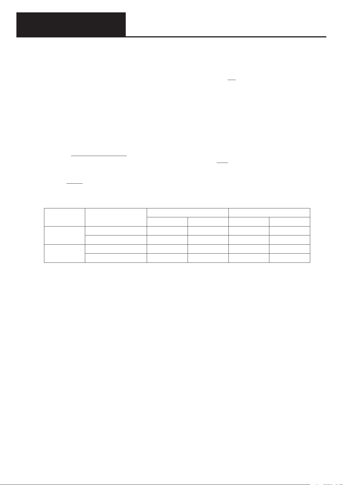
System Design
In the diagram above,
G : Position of center-of-gravity of equipment
W : Weight (N) of equipment alone
Rb : Pull-out force of one mounting bolt (N)
n : Total no. of mounting bolts
nt : No. of mounting bolts on one side subject to tension
by toppling force (in the direction being considered)
hG : Height of unit center-of-gravity above mounting
surface (mm)
L : Bold span (mm) from direction of concern
(L1 : End-on direction, L2 = Broadside direction)
LG : Distance from center-of-bolt to center-of-gravity as
viewed from direction of concern (but LG ≤ /2 (mm))
Mounting bolt pull-out force
FH · hG - (W-FV) · L
Rb=
Mounting bolt shear stress
F
τ=
n · A
L · nt
H
7. Center-of-gravity and earthquake resistance
FH : Design horizontal force (N)
(FH =KH · W)
FV : Design vertical force (N)
1
FV =
A : Nominal cross-sectional area of one
mounting bolt (mm2)
τ: Shear stress on bolt (N/ mm2)
fts : Allowable tensile stress on a bolt with
simultaneous shear stress (N/ mm2)
However, fts ≤ ft
Mounting bolt tensile stress
G
δ=
Allowable tensile stress on a bolt with
simultaneous shear stress
fts = 1.4ft - 1.6τ
F
H
2
R
b
A
Table of allowable stress on bolts Units (N/ mm2)
Bolt material Bolt diameter
SS400
SUS304
40 mm or less 118 88 176 132
More than 40 mm 108 80 162 121
40 mm or less 137 103 206 154
More than 40 mm 126 94 188 141
Long-term allowable stress Short-term allowable stress
Tension (ft) Shear (fs) Tension (ft) Shear (fs)
Notes
1) The values in the above table are derived from “Steel structure design criteria” published by the Architects
Institute of Japan.
2) Use the value ft in the table if necessary to investigate bolt tensile stress.
3) Strength of a bolt subject to simultaneous tension and shear can be checked as follows.
a) τ f
s
b) σ ≤ the smaller of ft or fts, but fts = 1.4ft – 1.6τ
where, τ : Shear stress on bolt
σ : Tensile stress on bolt (σ = Rb/A)
fs : Allowable stress on bolt with shear stress only (value from above table)
ft : Allowable stress on bolt with tensile stress only (value from above table)
fts : Allowable tensile stress on a bolt with simultaneous shear stress, but fts ≤ f
t
4) The allowable tensile stresses in the above table are evaluated using the cross-sectional area of the
minor diameter of the screw thread. However, when calculating for selection purposes, the cross-sectional
area based upon the nominal diameter may be used.
5) If the threaded portion is subject to shear, then if using the cross-sectional area based upon the nominal
diameter, multiply the value of fs in the above table by 0.75.
D-38
Page 92
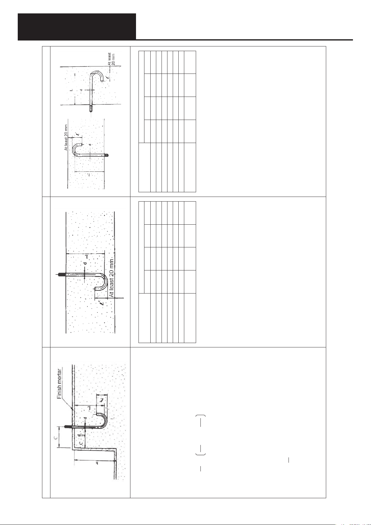
System Design
7. Center-of-gravity and earthquake resistance
=
C
Concrete thickness (mm)
c) Bottom surface of normal ceiling slab, concrete wall surface
120 150 180 200
Long-term allowable pull-out load (N)
M 8 5880 5880 5880 5880
M10 7840 7840 7840 7840
M12 7840 7840 7840 7840
d (nominal)
Bolt diameter
Concrete thickness (mm)
120 150 180 200
Short-term pull-out load (N)
M 8 8820 8820 8820 8820
M10 11760 11760 11760 11760
M12 11760 11760 11760 11760
d (nominal)
Bolt diameter
M16 - 7840 7840 7840
M20 - - 7840 7840
M16 - 11760 11760 11760
M20 - - 11760 11760
100-d 130-d 160-d 180-d
M24 - - - 7840
Length of bolt
embedded, L (mm)
Notes
100-d 130-d 160-d 180-d
M24 - - - 11760
Length of bolt
embedded, L (mm)
Notes
as shown in the diagram above.
1. These are short-term allowable pull-out loads for bolts embedded
as shown in the diagram above.
1. These are short-term allowable pull-out loads for bolts embedded
.
2
17.6 N/mm
2. The concrete design characteristic strength is taken to be F
3. When the dimensions differ from the above diagram, or if the
=
C
.
2
17.6 N/mm
2. The concrete design characteristic strength is taken to be F
3. When the dimensions differ from the above diagram, or if the
concrete design characteristic strength differs, then the pull-out
load can be calculated according with the formulae for bolts in a
strong foundation, at the left, and divide the result by 1.5 to obtain
the allowable pull-out load. In any case, the allowable pull-out load
on one bolt must not exceed 7,840 N.
4. It is desirable that L ≥ 6d. The conditions indicated by “-” in the
concrete design characteristic strength differs, then the pull-out
load can be calculated according with the formulae for bolts in a
strong foundation, at the left. In any case, the allowable pull-out
load on one bolt must not exceed 11,760 N.
above table should be avoided.
4. It is desirable that L ≥ 6d. The conditions indicated by “-” in the
above table should be avoided.
normal supports with regard to earthquakes when the supports
5. In the above diagram, l is approx. 4.5 d for a JIS bolt.
6. It is necessary to investigate the short-term pull-out load of
5. In the above diagram, is approx. 4.5 d for a JIS bolt.
6. If type 1 or 2 lightweight concrete is used, allow 10% margin.
are installed in the bottom of ceiling slabs and on concrete walls
designed to support heavy objects. For this short-term pull-out
load, see Item b, “Short-term pull-out loads.”
7. If type 1 or 2 lightweight concrete is used, allow 10% margin.
Installation location: a) Solid foundation b) Upper surface of normal floor slab
(1) Allowable pull-out force of embedded J- and JA-type bolts
Short-term allowable pull-out load of a bolt is obtained with the
following formulae. However, if the shear stress on the bolt exceeds
· p …(a)
2
(for SS400), bolt strength and assurance that allowable
2
Ta=6π · L
44.1 N/mm
tensile stress is not exceeded must be verified.
)
2
is used.)
2
Fc
100
, 0.49 +
Fc
30
Min
(Normally, 17.6 N/mm
1
6
= Concrete design characteristic strength (N/mm
Ta = Anchor bolt allowable short-term pull-out load (N)
L = Embedded length of anchor bolt (mm)
p = Correction factor for concrete design strength is
Where,
However, L must be between 60 and 300
P =
C
F
For bolts near a corner or edge of a foundation, if the distance from
the center of the bolt to the edge is C ≤ L, the allowable short-term
pull-out load of the bolt is given by either formula (b) or (c) below.
D-39
· p …(b)
2
Ta=6π · C
1) For L ≤ C + h,
· p …(c)
2
Ta=6π · (L · h)
Where C = the distance from the edge of the foundation to the
center of the bolt (mm)
2) For L > C + h,
C ≥ 50 mm
1
However, L ≥ C ≥ 4d, and
2
h = Foundation pad height (mm)
Notes
1. L should be ≥ 6d (where d = nominal anchor bolt diameter).
2. In the above diagram, is approx. 4.5 d for a JIS bolt.
3. If type 1 or 2 lightweight concrete is used, allow 10% margin.
Page 93
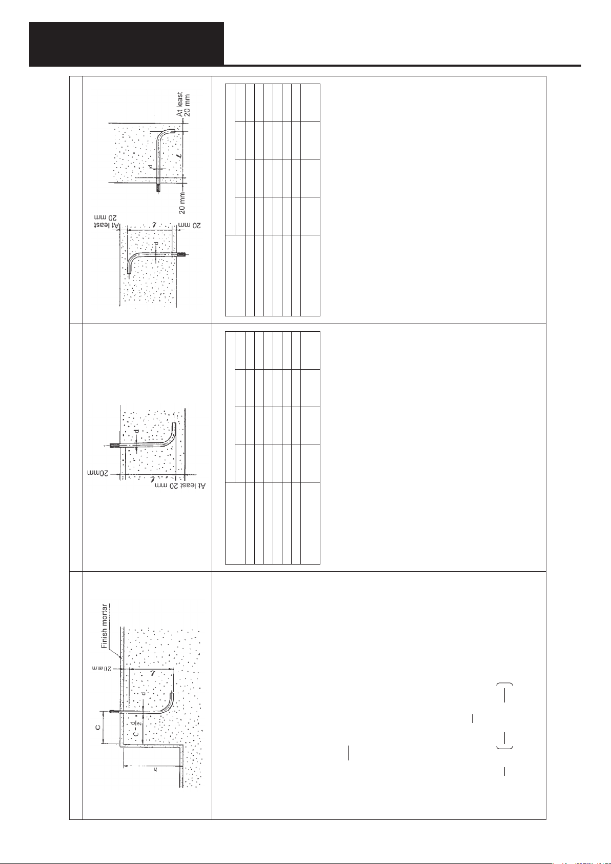
System Design
7. Center-of-gravity and earthquake resistance
=
C
Concrete thickness (mm)
120 150 180 200
80 110 140 160
c) Bottom surface of normal ceiling slab, concrete wall surface
Long-term allowable pull-out load (N)
M 8 2058 2842 3724 4214
M10 2548 3528 4606 5292
M12 3136 4312 5488 6272
d (nominal)
Bolt diameter
Concrete thickness (mm)
120 150 180 200
Short-term pull-out load (N)
M 8 3136 4312 5586 6370
M10 3920 5390 6958 7938
M12 4704 6566 8330 9506
d (nominal)
Bolt diameter
M16 - 5782 7448 7840
M20 - - 7840 7840
M16 - 8722 11172 11760
M20 - - 11760 11760
M24 - - - 7840
length ( ) (mm)
Effective embedded
80 110 140 160
M24 - - - 11760
length ( ) (mm)
Effective embedded
Notes
1. These are short-term allowable pull-out loads for bolts embedded
Notes
1. These are short-term allowable pull-out loads for bolts embedded
2
as shown in the diagram above.
2. The concrete design characteristic strength is taken to be F
=
C
2
as shown in the diagram above.
2. The concrete design characteristic strength is taken to be F
.
17.6 N/mm
concrete design characteristic strength differs, then the pull-out
load can be calculated according with the formulae for bolts in a
3. When the dimensions differ from the above diagram, or if the
.
17.6 N/mm
concrete design characteristic strength differs, then the pull-out
load can be calculated according with the formulae for bolts in a
3. When the dimensions differ from the above diagram, or if the
strong foundation, at the left, and divide the result by 1.5 to obtain
the allowable pull-out load. In any case, the allowable pull-out load
on one bolt must not exceed 7,840 N.
above table should be avoided.
4. It is desirable that L ≥ 6d. The conditions indicated by “-” in the
strong foundation, at the left. In any case, the allowable pull-out
load on one bolt must not exceed 11,760 N.
above table should be avoided.
4. It is desirable that L ≥ 6d. The conditions indicated by “-” in the
5. If type 1 or 2 lightweight concrete is used, allow 10% margin.
of normal supports with regard to earthquakes when the supports
are installed in the bottom of ceiling slabs and on concrete walls
designed to support heavy objects.
5. It is necessary to investigate item b), the short-term pull-out load
6. If type 1 or 2 lightweight concrete is used, allow 10% margin.
(for SS400), bolt strength and assurance that allowable
2
Installation location: a) Solid foundation b) Upper surface of normal floor slab
(2) Allowable pull-out load of embedded L- and LA-type bolts
Short-term allowable pull-out load of a bolt is obtained with the
following formulae. However, if the shear stress on the bolt exceeds
44.1 N/mm
tensile stress is not exceeded must be verified.
C
F
9
100
(the length from 20mm below the surface of the concrete
foundation.)
= Embedded length of anchor bolt (mm).
Ta = Anchor bolt allowable short-term pull-out load (N)
d = Anchor bolt nominal diameter (mm)
Ta = π · d · · fc …(a)
Where,
fc =
fc = short-term allowable bond stress in reinforced concrete
D-40
)
2
is used.)
2
(Normally, 17.6 N/mm
= Concrete design characteristic strength (N/mm
C
F
(from “Standard for RC structures design,” published by the
Architectural Institute of Japan)
For anchor bolts positioned in the corner or near the edge of the
foundation, the short-term allowable pull-out load shall be taken
to be the minimum of the values from formulae (b) below, and (a).
· p …(b)
2
Ta = 6 π · C
Where C = the distance from the edge of the foundation to the center
of the bolt (mm)
Fc
100
≥ 50 mm
d
2
, 0.49 +
Fc
30
Min
1
6
P =
However, C ≥ 4d, and C -
p = Correction factor for concrete design strength is
Notes
1. L should be ≥ 6d (where d = nominal anchor bolt diameter).
2. If type 1 or 2 lightweight concrete is used, allow 10% margin.
Page 94
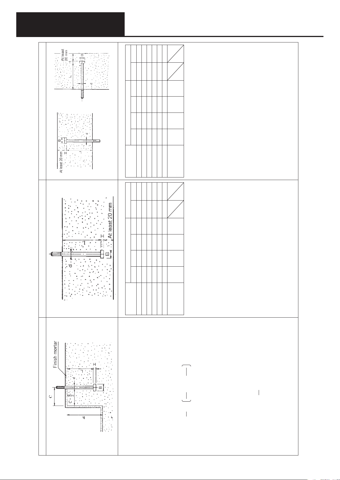
System Design
c) Bottom surface of normal ceiling slab, concrete wall surface
7. Center-of-gravity and earthquake resistance
=
C
Concrete thickness (mm) Bolt size
120 150 180 200 H (mm) B (mm)
Long-term allowable pull-out load (N)
M 8 5880 5880 5880 5880 55 13
M10 7840 7840 7840 7840 7 17
M12 7840 7840 7840 7840 8 19
d (nominal)
Bolt diameter
M16 - 7840 7840 7840 10 24
M20 - - 7840 7840 13 30
M24 - - - 7840 15 36
Length of bolt
100-H 130-H 160-H 180-H
(mm)
embedded, L
Notes
1. These are short-term allowable pull-out loads for bolts embedded
2
as shown in the diagram above.
2. The concrete design characteristic strength is taken to be F
=
C
.
17.6 N/mm
concrete design characteristic strength differs, then the pull-out
load can be calculated according with the formulae for bolts in a
3. When the dimensions differ from the above diagram, or if the
strong foundation, at the left, and divide the result by 1.5 to obtain
the allowable pull-out load. In any case, the allowable pull-out load
on one bolt must not exceed 7,840 N.
above table should be avoided.
4. It is desirable that L ≥ 6d. The conditions indicated by “-” in the
normal supports with regard to earthquakes when the supports
are installed in the bottom of ceiling slabs and on concrete walls
5. It is necessary to investigate the short-term pull-out load of
designed to support heavy objects. For this short-term pull-out
load, see Item b, “Short-term pull-out loads.”
6. If type 1 or 2 lightweight concrete is used, allow 10% margin.
Concrete thickness (mm) Bolt size
Short-term pull-out load (N)
Bolt diameter
2
Installation location: a) Solid foundation b) Upper surface of normal floor slab
(3) Allowable pull-out load of embedded bolts with heads
Short-term allowable pull-out load of a bolt is obtained with the
following formulae. However, if the shear stress on the bolt exceeds
120 150 180 200 H (mm) B (mm)
M 8 8820 8820 8820 8820 55 13
M10 11760 11760 11760 11760 7 17
M12 11760 11760 11760 11760 8 19
d (nominal)
(for SS400), bolt strength and assurance that allowable
Ta=6π · L(L+B) · p …(a)
Where,
44.1 N/mm
tensile stress is not exceeded must be verified.
100-H 130-H 160-H 180-H
.
2
M16 - 11760 11760 11760 10 24
M20 - - 11760 11760 13 30
M24 - - - 11760 15 36
(mm)
embedded, L
Length of bolt
in concrete of various thicknesses as shown in the above diagram.
Notes
1. The table shows the short-term pull-out load for bolts embedded
)
2
17.6 N/mm
2. The concrete design characteristic strength is taken to be F
3. When the dimensions differ from the above diagram, or if the
Fc
100
is used.)
2
, 0.49 +
Fc
30
Min
1
6
P =
of JIS standard hex bolt head)
Ta = Anchor bolt allowable short-term pull-out load (N)
d = Anchor bolt nominal diameter (mm)
B = Minimum bolt head width (mm), (distance across flat sides
p = Correction factor for concrete design strength is
(Normally, 17.6 N/mm
= Concrete design characteristic strength (N/mm
C
F
For bolts near a corner or edge of a foundation, if the distance from
the center of the bolt to the edge is C ≤ L + B, the allowable short-term
pull-out load of the bolt is given by either formula (b) or (c) below.
concrete design characteristic strength differs, then the pull-out
load can be calculated according with the formulae for bolts in a
strong foundation, at the left. In any case, the allowable pull-out
load on one bolt must not exceed 11,760 N.
4. It is desirable that L ≥ 6d. The conditions indicated by “-” in the
· p …(b)
· p …(c)
2
2
Ta=6π · C
Ta=6π · C
1) For L ≤ C + h,
2) For L > C + h,
Where C = the distance from the edge of the foundation to the center
of the bolt (mm)
above table should be avoided.
across the flat sides of the head and the thickness of the head,
respectively, for JIS standard hex bolt.
5. Dimensions B and H in the above diagram are the distance
6. If type 1 or 2 lightweight concrete is used, allow 10% margin.
≥ 50 mm
d
2
a JIS standard hex bolt head.
However, L + B ≥ C, and C -
h = Foundation pad height (mm)
Notes
1. L should be ≥ 6d (where d = nominal anchor bolt diameter).
2. Thickness H in the above diagram should be no less than that of
3. If type 1 or 2 lightweight concrete is used, allow 10% margin.
D-41
Page 95
System Design
c) Bottom surface of normal ceiling slab, concrete wall surface
7. Center-of-gravity and earthquake resistance
Concrete thickness (mm)
120 150 180 200
M 8 4802 6762 8232 8820
M10 4802 6762 8232 9408
Long-term allowable pull-out load (N)
Bolt diameter
M12 - 6762 8232 9408
d (nominal)
M16 - - 8232 9408
M20 - - 8232 9408
80-d 110-d 140-d 160-d
M24 - - - 9408
Length of bolt
embedded, L (mm)
Notes
=
C1
2
2
embedded as shown in the diagram above, with F
1. These are short-term allowable pull-out loads for bolts
=
C1
, and W = 100 mm.
= 17.6 N/mm
C2
, F
20.6 N/mm
or if the concrete design characteristic strength differs,
then the pull-out load can be calculated according with
the formulae for bolts in a strong foundation, at the left.
2. When the dimensions differ from the above diagram,
must not exceed 11,760 N.
“-” in the above table should be avoided.
150 mm.
In any case, the allowable pull-out load on one bolt
3. It is desirable that L ≥ 6d. The conditions indicated by
4. The above table can be used for boxout widths up to
margin.
5. If type 1 or 2 lightweight concrete is used, allow 10%
Concrete thickness (mm)
120 150 180 200
Short-term pull-out load (N)
M 8 3136 4508 5488 6272
M10 3136 4508 5488 6272
M12 - 4508 5488 6272
d (nominal)
Bolt diameter
(for SS400), bolt strength and
2
M16 - - 5488 6272
M20 - - 5488 6272
80-d 110-d 140-d 160-d
M24 - - - -
Length of bolt
embedded, L (mm)
Notes
)
2
, and W = 100 mm.
2
= 17.6 N/mm
C2
, F
2
embedded as shown in the diagram above, with F
11.8 N/mm
1. These are short-term allowable pull-out loads for bolts
)
2
are used.
2
= 17.6 N/mm
C2
2. When the dimensions differ from the above diagram,
or if the concrete design characteristic strength differs,
then the pull-out load can be calculated according with
the formulae for bolts in a strong foundation, at the left.
In any case, the allowable pull-out load of one bolt
must not exceed 11,760 N.
“-” in the above table should be avoided.
150 mm.
3. It is desirable that L ≥ 6d. The conditions indicated by
4. The above table can be used for boxout widths up to
5. If type 1 or 2 lightweight concrete is used, allow 10%
margin.
(4) Allowable pull-out load of J- and JA-type bolts and headed bolts in boxouts
(Boxout techniques are not applicable to the underside of ceiling slabs or concrete wall surfaces)
Installation location: a) Solid foundation b) Upper surface of normal floor slab
Short-term allowable pull-out load of a bolt is obtained with the following formulae.
However, if the shear stress on the bolt exceeds 44.1 N/mm
assurance that allowable tensile stress is not exceeded must be verified.
C2
≤ F
C1
For F
π · L · W …(a)
C1
F
Ta =
80
(e.g., in non-shrink mortar)
C2
> F
C1
For F
π · L · W …(a)
C2
80
F
Ta =
Where,
Ta = Anchor bolt allowable short-term pull-out load (N)
D-42
and F
2
= 11.8 N/mm
C1
= Characteristic design strength of backfill mortar (N/mm
C1
L = Embedded length of anchor bolt (mm)
F
Use the smallest dimension for rectangular shapes. However, the internal surfaces
= Characteristic design strength of surrounding concrete (N/mm
C2
F
Normally, F
W = Width of anchor bolt boxout (between 100mm and 150mm).
and L ≤ h,
C2
≤ F
C1
of the box insert must be sufficiently roughened.
1) For F
For anchor bolts positioned in the corner or near the edge of the foundation, the short-term allowable
pull-out load shall be taken to be either of the values from formulae (c) and (d) or (e) and (f) below.
…(c)
A
π · L · W
C1
F
Ta =
10
80
h ) …(d)
A
10
and L ≤ h,
and L > h,
C2
C2
π · L · W ( L - h +
≤ F
> F
C1
80
C1
C1
F
Ta =
2) For F
3) For F
…(e)
A
π · L · W
C2
F
Ta =
h ) …(f)
A
10
and L > h,
C2
π · L · W ( L - h +
> F
C2
80
C1
F
Ta =
4) For F
10
80
Where,
h = Foundation pad height (mm)
A = Distance from edge of anchor boxout to edge of foundation pad (mm)
Notes 1. L should be ≥ 6d (where d = nominal anchor bolt diameter).
2. If type 1 or 2 lightweight concrete is used, allow 10% margin.
Page 96
System Design
7. Center-of-gravity and earthquake resistance
=
C1
, and W = 100 mm.
2
c) Bottom surface of normal ceiling slab, concrete wall surface
Concrete thickness (mm)
120 150 180 200
M 8 2352 3528 4704 5586
M10 2940 4410 5978 6958
M12 - 5292 7154 8330
Long-term allowable pull-out load (N)
d (nominal)
Bolt diameter
Concrete thickness (mm)
120 150 180 200
M16 - - 8232 9408
Short-term pull-out load (N)
M 8 1568 2352 3136 3724
M10 1960 2940 3920 4606
M12 - 3528 4704 5586
M16 - - 5488 6272
d (nominal)
Bolt diameter
80-d 110-d 140-d 160-d
M20 - - 8232 9408
M24 - - - 9408
Length of bolt
embedded, L (mm)
80-d 110-d 140-d 160-d
M20 - - 5488 6272
M24 - - - 6272
Length of bolt
embedded, L (mm)
60 90 120 140
Notes
1. These are short-term allowable pull-out loads for bolts
embedded as shown in the diagram above, with F
=
C1
embedded, ( ) (mm)
Effective length of bolt
60 90 120 140
Notes
1. These are short-term allowable pull-out loads for bolts
embedded as shown in the diagram above, with F
embedded, ( ) (mm)
Effective length of bolt
= 17.6 N/mm
C2
, F
2
20.6 N/mm
or if the concrete design characteristic strength differs,
then the pull-out load can be calculated according with
2. When the dimensions differ from the above diagram,
, and W = 100 mm.
2
= 17.6 N/mm
C2
, F
2
11.8 N/mm
or if the concrete design characteristic strength differs,
then the pull-out load can be calculated according with
2. When the dimensions differ from the above diagram,
the formulae for bolts in a strong foundation, at the left.
must not exceed 11,760 N.
“-” in the above table should be avoided.
In any case, the allowable pull-out load on one bolt
3. It is desirable that L ≥ 6d. The conditions indicated by
the formulae for bolts in a strong foundation, at the left.
In any case, the allowable pull-out load on one bolt
must not exceed 11,760 N.
“-” in the above table should be avoided.
3. It is desirable that L ≥ 6d. The conditions indicated by
150 mm.
margin.
4. The above table can be used for boxout widths up to
5. If type 1 or 2 lightweight concrete is used, allow 10%
150 mm.
margin.
4. The above table can be used for boxout widths up to
5. If type 1 or 2 lightweight concrete is used, allow 10%
(for
2
)
2
)
2
are used.
2
= 17.6 N/mm
C2
and F
C2
≤ F
C1
For F
π · L · W …(a)
C1
F
Ta =
80
(e.g., in non-shrink mortar)
C2
> F
C1
For F
π · L · W …(b)
C2
80
F
Ta =
Where,
Ta = Anchor bolt allowable short-term pull-out load (N)
2
= 11.8 N/mm
C1
= Characteristic design strength of backfill mortar (N/mm
C1
L = Embedded length of anchor bolt (mm)
F
Use the smallest dimension for rectangular shapes. However, the internal surfaces
= Characteristic design strength of surrounding concrete (N/mm
C2
F
Normally, F
W = Width of anchor bolt boxout (between 100mm and 150mm).
and L ≤ h,
C2
≤ F
C1
of the box insert must be sufficiently roughened.
1) For F
…(c)
A
π · L · W
C1
F
Ta =
10
80
h ) …(d)
A
10
and L ≤ h,
and L > h,
C2
C2
π · L · W ( L - h +
≤ F
> F
C1
80
C1
C1
F
Ta =
2) For F
3) For F
…(e)
A
π · L · W
C2
F
Ta =
10
80
h ) …(f)
A
10
and L > h,
C2
π · L · W ( L - h +
> F
C2
80
C1
F
Ta =
4) For F
(5) Allowable pull-out load of embedded L- and LA-type bolts in boxouts
(Boxout techniques are not applicable to the underside of ceiling slabs or concrete wall surfaces)
Installation location: a) Solid foundation b) Upper surface of normal floor slab
The short-term allowable pull-out load of a bolt is the smaller of the value obtained from formula (a)
in item (2) or the following formulae. However, if the pull-out load on the bolt exceeds 14.7 N/mm
SS400), bolt strength and assurance that allowable tensile stress is not exceeded must be verified.
D-43
For anchor bolts positioned in the corner or near the edge of the foundation, the short-term allowable pull-out
load shall be taken to be either of the values from formulae (a) in item (2), and (c) and (d) or (e) and (f) below.
Where,
h = Foundation pad height (mm) A : A = Distance from edge of anchor boxout to edge of
foundation pad (mm), and A is greater than 100 mm, but not more than 150 mm
Notes 1. L should be ≥ 6d (where d = nominal anchor bolt diameter).
2. If type 1 or 2 lightweight concrete is used, allow 10% margin.
Page 97
System Design
c) Bottom surface of normal ceiling slab, concrete wall surface
7. Center-of-gravity and earthquake resistance
(mm)
2
Drilled
d
hole dia.
(mm)
length L
Embedded
Concrete thickness (mm)
120 150 180 200
Long-term allowable pull-out load (N)
M10 4900 4900 4900 4900 80 13.5
M12 5978 5978 5978 5978 90 14.5
d (nominal)
Bolt diameter
(mm)
2
Drilled
d
hole dia.
M16 - 7840 7840 7840 110 20
M20 - - 7840 7840 120 24
Length limit of
100 130 160 180
(mm)
Notes
1. The table shows the short-term allowable pull-out load for resin
anchor bolts embedded for the lengths shown in drilled holes with
embedded bolt
=
C
.
2
the indicated diameters.
17.6 N/mm
2. The concrete design characteristic strength is taken to be F
=
C
concrete design characteristic strength differs, then the pull-out
load can be calculated according with the formulae for bolts in a
strong foundation, at the left, and divide the result by 1.5 to obtain
the allowable pull-out load. In any case, the allowable pull-out load
3. When the dimensions differ from the above diagram, or if the
on one bolt must not exceed 7,840 N.
above table should be avoided.
normal supports with regard to earthquakes when the supports
4. It is desirable that L ≥ 6d. The conditions indicated by “-” in the
5. It is necessary to investigate the short-term pull-out load of
are installed in the bottom of ceiling slabs and on concrete walls
designed to support heavy objects. For this short-term pull-out
load, see Item b, “Short-term pull-out loads.”
6. If type 1 or 2 lightweight concrete is used, allow 10% margin.
(mm)
length L
Embedded
Short-term pull-out load (N)
Concrete thickness (mm)
120 150 180 200
M10 7448 7448 7448 7448 80 13.5
M12 9016 9016 7448 9016 90 14.5
d (nominal)
Bolt diameter
M16 - 11760 9016 11760 110 20
M20 - - 11760 11760 120 24
Length limit of
100 130 160 180
(mm)
Notes
1. The table shows the short-term allowable pull-out load for resin
anchor bolts embedded for the lengths shown in drilled holes with
embedded bolt
)
2
.
2
the indicated diameters.
17.6 N/mm
2. The concrete design characteristic strength is taken to be F
concrete design characteristic strength differs, then the pull-out
load can be calculated according with the formulae for bolts in a
strong foundation, at the left. In any case, the allowable pull-out
load on one bolt must not exceed 11,760 N.
3. When the dimensions differ from the above diagram, or if the
above table should be avoided.
4. It is desirable that L ≥ 6d. The conditions indicated by “-” in the
5. If type 1 or 2 lightweight concrete is used, allow 10% margin.
Fc
100
.
exceeds 29.4 N/
2
C
Installation location: a) Solid foundation b) Upper surface of normal floor slab
(6) Allowable pull-out load of post-drilled resin anchors
Short-term allowable pull-out load of a bolt is obtained with the
following formulae. However, if the shear stress on the bolt exceeds
· L …(a)
2
(for SS400), bolt strength and assurance that allowable
2
π · d
Fc
Ta=
44.1 N/mm
tensile stress is not exceeded must be verified.
· p …(b)
2
8
= Concrete design characteristic strength (N/mm
= Diameter of drilled hole in concrete (mm)
C
2
Ta = Anchor bolt allowable short-term pull-out load (N)
L = Embedded length of anchor bolt (mm)
d
F
Ta=6π · C
Where,
For foundation bolts positioned near a corner or edge of the
foundation, the short-term allowable pull-out strength shall be taken
to be the minimum of the values from formula (a) above, or formula
(b) or (c) below.
1) For L ≤ C + h,
D-44
p …(c)
2
Ta=6π(L-h)
2) For L > C + h,
Where C = the distance from the edge of the foundation to the center
of the bolt (mm)
≥ 50 mm
d
2
, 0.49 +
Fc
30
Min
1
6
P =
However, C ≥ 4d, and C -
p = Correction factor f or concrete design strength is
Notes
of the drilled hole in concrete should be that
2
, perform the calculation using 29.4 N/mm
2
mm
recommended by the resin anchor bolt manufacturer.
1. L should be ≥ 6d (where d = nominal anchor bolt diameter).
2. If the concrete design characteristic strength F
3. Diameter d
4. If type 1 or 2 lightweight concrete is used, allow 10% margin.
Page 98
System Design
c) Bottom surface of normal ceiling slab, concrete wall surface
7. Center-of-gravity and earthquake resistance
=
C
length L (mm)
less
180 or
less
160 or
less
120 or
Concrete thickness (mm) Embedded
120 150 180 200
Long-term allowable pull-out load (N)
M8 1960 1960 1960 1960 40
M10 2450 2450 2450 2450 45
M12 4410 4410 4410 4410 60
M16 5978 5978 5978 5978 70
d (nominal)
Bolt diameter
M20 7840 7840 7840 7840 90
less
100 or
M24 7840 7840 7840 7840 100
(mm)
Length limit of
embedded bolt
Notes
1. The above table shows the short-term allowable pull-out load for
.
2
anchor bolts embedded for the lengths shown.
17.6 N/mm
2. The concrete design characteristic strength is taken to be F
=
C
concrete design characteristic strength differs, then the pull-out
load can be calculated according with the formulae for bolts in a
strong foundation, at the left, and divide the result by 1.5 to obtain
the allowable pull-out load. In any case, the allowable pull-out load
3. When the dimensions differ from the above diagram, or if the
on one bolt must not exceed 7,840 N.
in the rightmost column.
normal supports with regard to earthquakes when the supports
4. Do not use bolts with an embedded length less than that shown
5. It is necessary to investigate the short-term pull-out load of
are installed in the bottom of ceiling slabs and on concrete walls
designed to support heavy objects. For this short-term pull-out
load, see Item b, “Short-term pull-out loads.”
6. If type 1 or 2 lightweight concrete is used, allow 10% margin.
length L (mm)
Concrete thickness (mm) Embedded
120 150 180 200
Short-term pull-out load (N)
M8 2940 2940 2940 2940 40
M10 3724 3724 3724 3724 45
M12 6566 6566 6566 6566 60
M16 9016 9016 9016 9016 70
d (nominal)
Bolt diameter
180 or
160 or
120 or
100 or
M20 11760 11760 11760 11760 90
M24 11760 11760 11760 11760 100
Length limit of
less
less
less
less
(mm)
embedded bolt
Notes
1. The above table shows the short-term allowable pull-out load for
.
2
anchor bolts embedded for the lengths shown.
17.6 N/mm
2. The concrete design characteristic strength is taken to be F
concrete design characteristic strength differs, then the pull-out
load can be calculated according with the formulae for bolts in a
strong foundation, at the left. In any case, the allowable pull-out
load on one bolt must not exceed 11,760 N.
3. When the dimensions differ from the above diagram, or if the
in the rightmost column.
4. Do not use bolts with an embedded length less than that shown
5. If type 1 or 2 lightweight concrete is used, allow 10% margin.
Installation location: a) Solid foundation b) Upper surface of normal floor slab
(7) Allowable pull-out load for post-installed screw-type mechanical anchor bolts
Short-term allowable pull-out load of a bolt is obtained with the
following formulae. However, if the shear stress on the bolt exceeds
· p …(a)
2
(for SS400), bolt strength and assurance that allowable
2
Ta= 6π · L
44.1 N/mm
tensile stress is not exceeded must be verified.
Fc
100
, 0.49 +
Fc
30
Min
(Normally, 17.6 N/mm2 is used.)
1
(May be taken to be the depth of the drilled hole.)
Ta = Anchor bolt allowable short-term pull-out load (N)
L = Embedded length of anchor bolt (mm)
6
= Concrete design characteristic strength (N/mm2)
P =
C
F
P = Correction factor for concrete design strength is
· p …(b)
2
Ta= 6π · C
Where,
For bolts near a corner or edge of a foundation, if the distance from
the center of the bolt to the edge is C ≤ L, the allowable short-term
pull-out load of the bolt is given by formula (b) below.
D-45
≥ 50 mm
d
2
Where C = the distance from the edge of the foundation to the center
of the bolt (mm)
However, C ≥ 4d, and C -
Note 1. If type 1 or 2 lightweight concrete is used, allow 10% margin.
Page 99
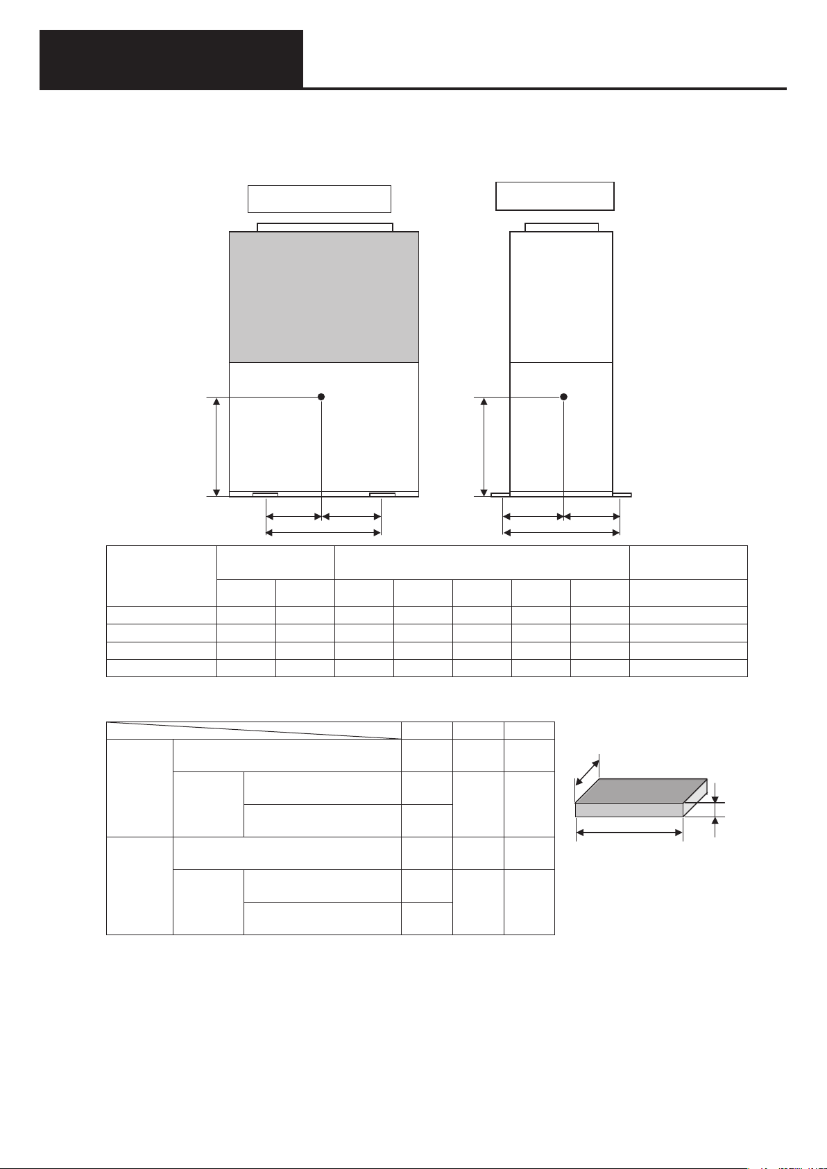
System Design
h
A
C
7. Center-of-gravity and earthquake resistance
(3) Installation position and center of gravity
For 2-WAY Type
Outdoor Unit
1) Position of center-of-gravity
End-on (side view)
h
G
L
G2
L
G
2
L
G2´
L
G2´
L
2
h
2WAY Multi/2WAY
G
Outdoor unit type
G
Position of
mounting points
L
1
Broadside (front view)
L
G1
L
G1´
L
1
L
2
L
G1
Position of center-of-gravity Unit Weight (kg)
L
G1´
45.0 kW 1,000 1,040 523 477 492 548 761 765
56.0 kW 1,000 1,040 523 477 492 548 761 765
71.0 kW 1,000 1,040 548 452 501 539 914 870
85.0 kW 1,000 1,040 548 452 501 539 914 880
For earthquake-resistant design, compare LG1 and L
, and LG2 and L
G1'
, and use the smallest value.
G2'
2) Mounting pad (foundation) size Unit: mm
A (mm) B (mm) C (mm)
45.0/56.0
kW
71.0/85.0
kW
Installation on ground
Without vibration-resistant
Installation
on roof
frame
With vibration-resistant
frame
Installation on ground
Without vibration-resistant
Installation
on roof
frame
With Vibration-resistant
frame
1,700
or more
1,850
or more
2,000
or more
2,100
or more
2,100
or more
2,200
or more
1,170
or more
2,000
or more
1,170
or more
2,000
or more
120 or
more
140 or
more
120 or
more
140 or
more
B
Note: The foundation is either a solid pad, or directly on the floor slab.
3) Size and type of anchor bolts
i) All anchor bolts are M12.
ii) Use one of the following types of anchor bolts.
Embedded-type: L-type, LA-type, headed bolts, J-type, JA-type
Boxout-compatible: L, LA, headed, J or JA (however, base dimension C must be at least 180 mm),
post-drilled resin anchors or post-installed male-threaded mechanical anchor bolts.
Female screw anchors provide insufficient pull-out strength, so cannot be used.
D-46
Page 100
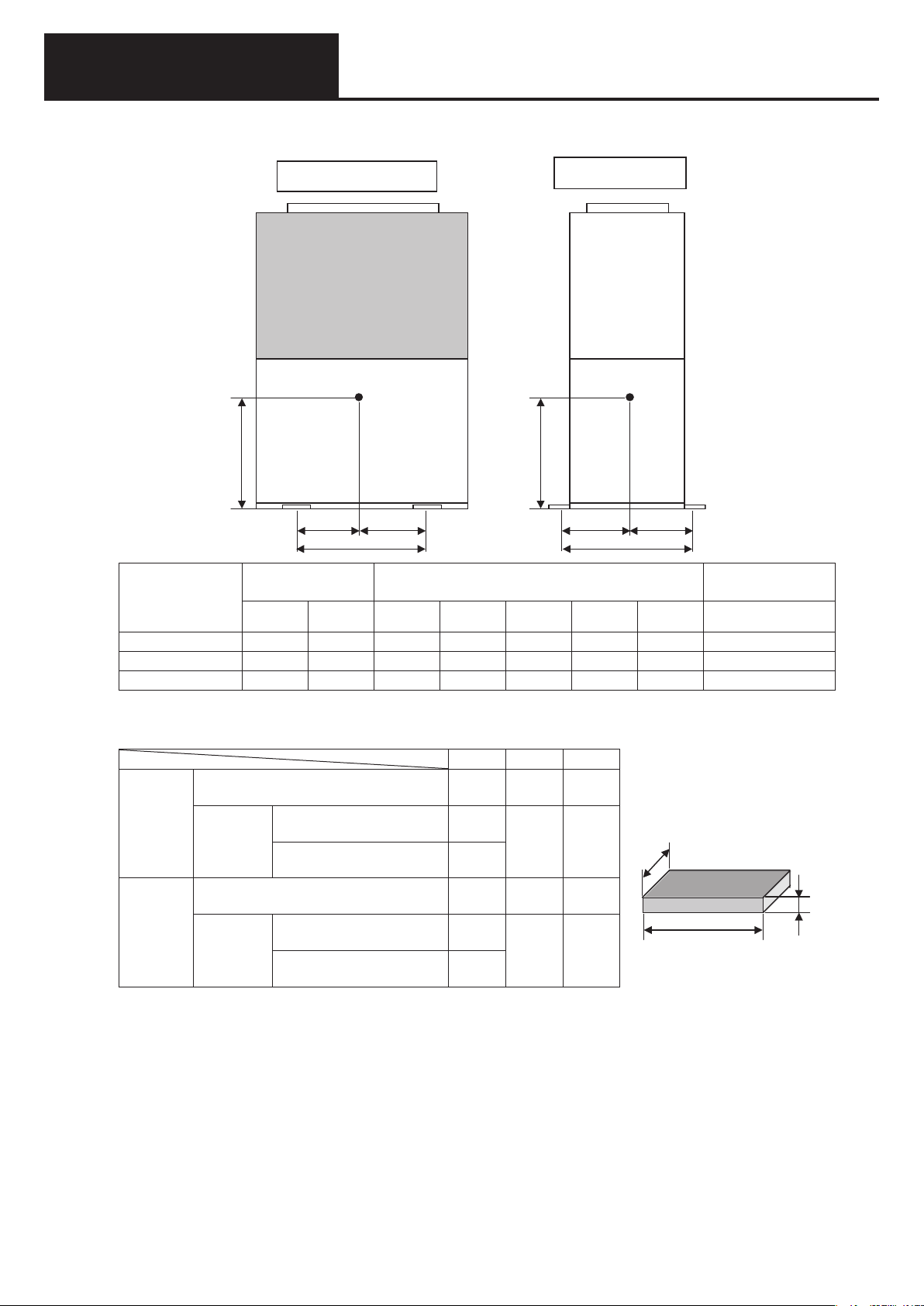
System Design
h
A
C
For 3-WAY Type
1) Position of center-of-gravity
7. Center-of-gravity and earthquake resistance
End-on (side view)
h
G
L
G2
L
G
2
L
G2´
L
G2´
L
2
h
G
Outdoor unit type
G
Position of
mounting points
L
1
Broadside (front view)
L
G1
L
G1´
L
1
L
2
L
G1
Position of center-of-gravity Unit Weight (kg)
L
G1´
45.0 kW 1,000 1,040 535 465 499 541 801 775
56.0 kW 1,000 1,040 535 465 499 541 801 775
71.0 kW 1,000 1,040 536 464 514 526 883 880
3WAY
For earthquake-resistant design, compare LG1 and L
, and LG2 and L
G1'
, and use the smallest value.
G2'
2) Mounting pad (foundation) size Unit: mm
A (mm) B (mm) C (mm)
45.0/56.0
kW
71.0kW
Installation on ground
Without vibration-resistant
Installation
on roof
frame
With vibration-resistant
frame
Installation on ground
Without vibration-resistant
Installation
on roof
frame
With Vibration-resistant
frame
1,700
or more
1,850
or more
2,000
or more
2,100
or more
2,100
or more
2,200
or more
1,170
or more
2,000
or more
1,170
or more
2,000
or more
120 or
more
140 or
more
120 or
more
140 or
more
B
Note: The foundation is either a solid pad, or directly on the floor slab.
3) Size and type of anchor bolts
i) All anchor bolts are M12.
ii) Use one of the following types of anchor bolts.
Embedded-type: L-type, LA-type, headed bolts, J-type, JA-type
Boxout-compatible: L, LA, headed, J or JA (however, base dimension C must be at least 180 mm),
post-drilled resin anchors or post-installed male-threaded mechanical anchor bolts.
Female screw anchors provide insufficient pull-out strength, so cannot be used.
D-47
 Loading...