

Page 1
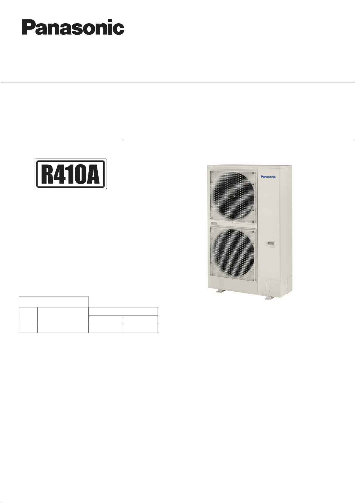
Order No. SBPAC1605017CE
SERVICE MANUAL & TEST RUN SERVICE MANUAL
Mini VRF SYSTEM
Model No.
Outdoor Units
Type Outdoor Unit Type
LE1
mini VRF System U-8LE1E8 U-10LE1E8
HP = horsepower
Rated Capacity
8 HP 10 HP
85464849348000
REFERENCE NO.SM830248-00
Page 2
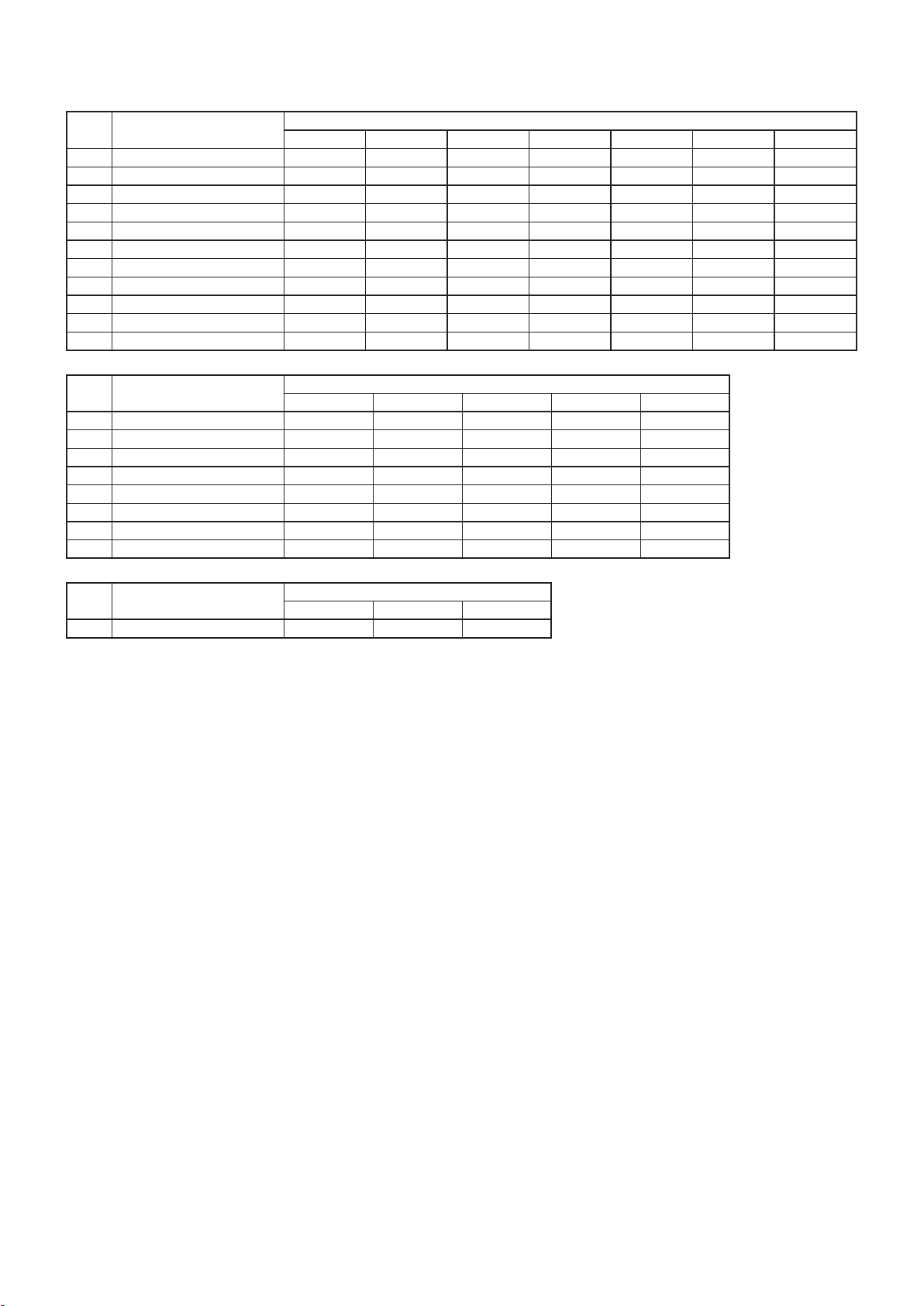
Model No.
IMPORTANT!
Please Read Before Starting
This air conditioner must be installed by the sales dealer
or installer.
This information is provided for use only by authorized
persons.
For safe installation and trouble-free operation, you
must:
Carefully read this instruction booklet before beginning.
Follow each installation or repair step exactly as shown.
This air conditioner shall be installed in accordance with
National Wiring Regulations.
This product is intended for professional use.
This equipment complies with EN/IEC 61000-3-12
provided that the short-circuit power Ssc is greater than
or equal to the following table at the interface point
between the user’s supply and the public system.
It is the responsibility of the installer or user of
the equipment to ensure, by consultation with the
distribution network operator if necessary, that the
equipment is connected only to a supply with a short-
circuit power Ssc greater than or equal to the value in
the table.
Permission from the power supplier is required when
installing the 8 HP outdoor unit that is connected to a
16 A distribution network.
The product meets the technical requirements of
EN/IEC 61000-3-3.
Pay close attention to all warning and caution notices
given in this manual.
WARNING
This symbol refers to a hazard or unsafe
practice which can result in severe
personal injury or death.
CAUTION
This symbol refers to a hazard or unsafe
practice which can result in personal
injury or product or property damage.
If Necessary, Get Help
These instructions are all you need for most installation
sites and maintenance conditions. If you require help for
a special problem, contact our sales/service outlet or your
certified dealer for additional instructions.
In Case of Improper Installation
The manufacturer shall in no way be responsible for
improper installation or maintenance service, including
failure to follow the instructions in this document.
SPECIAL PRECAUTIONS
WARNING When Wiring
ELECTRICAL SHOCK CAN
CAUSE SEVERE PERSONAL
INJURY OR DEATH. ONLY A
QUALIFIED, EXPERIENCED
ELECTRICIAN SHOULD
ATTEMPT TO WIRE THIS
SYSTEM.
• Do not supply power to the unit until
all wiring and tubing are completed or
reconnected and checked.
• Highly dangerous electrical voltages are
used in this system. Carefully refer to the
wiring diagram and these instructions
when wiring. Improper connections
and inadequate grounding can cause
accidental injury or death.
• Connect all wiring tightly. Loose wiring
may cause overheating at connection
points and a possible fire hazard.
• Provide a power outlet to be used
exclusively for each unit.
• ELCB must be incorporated in the
fixed wiring. Circuit breaker must be
incorporated in the fixed wiring in
accordance with the wiring regulations.
8 HP 10 HP
Circuit breaker 25 A 30 A
• Provide a power outlet exclusively for
each unit, and full disconnection means
having a contact separation by 3 mm
in all poles must be incorporated in the
fixed wiring in accordance with the wiring
rules.
• To prevent possible hazards from
insulation failure, the unit must be
grounded.
• This equipment is strongly recommended
to be installed with Earth Leakage
Circuit Breaker (ELCB) or Residual
Current Device (RCD). Otherwise, it may
cause electrical shock and fire in case
of equipment breakdown or insulation
breakdown.
Ssc 1,535 kVA
10 HP
•TobeconnectingIndoorUnit
Type Indoor Unit Type
D1 1-WayCassette
L1 2-WayCassette
U1 4-WayCassette
Y2 4-WayCassette60×60
K1 Wall-Mounted
K2 Wall-Mounted
T2 Ceiling
F2 LowSilhouetteDucted
M1 SlimLowStaticDucted
P1 FloorStanding
R1 ConcealedFloorStanding
Type Indoor Unit Type
D1 1-WayCassette
L1 2-WayCassette
U1 4-WayCassette
K1 Wall-Mounted
T2 Ceiling
F2 LowSilhouetteDucted
P1 FloorStanding
R1 ConcealedFloorStanding
Type Indoor Unit Type
HighStaticPressureDucted
E2
15 22 28 36 45 56 60
S-22ML1E5 S-28ML1E5 S-36ML1E5 S-45ML1E5 S-56ML1E5
S-22MU1E5A S-28MU1E5A S-36MU1E5A S-45MU1E5A S-56MU1E5A S-60MU1E5A
S-15MY2E5A S-22MY2E5A S-28MY2E5A S-36MY2E5A S-45MY2E5A S-56MY2E5A
S-15MK2E5A S-22MK2E5A S-28MK2E5A S-36MK2E5A
S-15MF2E5A S-22MF2E5A S-28MF2E5A S-36MF2E5A S-45MF2E5A S-56MF2E5A S-60MF2E5A
S-15MM1E5A S-22MM1E5A S-28MM1E5A S-36MM1E5A S-45MM1E5A S-56MM1E5A
S-22MP1E5 S-28MP1E5 S-36MP1E5 S-45MP1E5 S-56MP1E5
S-22MR1E5 S-28MR1E5 S-36MR1E5 S-45MR1E5 S-56MR1E5
71 / 73 90 106 140 160
S-73MD1E5
S-73ML1E5
S-73MU1E5A S-90MU1E5A S-106MU1E5A S-140MU1E5A S-160MU1E5A
S-73MK1E5A S-106MK1E5A
S-73MT2E5A S-106MT2E5A S-140MT2E5A
S-73MF2E5A S-90MF2E5A S-106MF2E5A S-140MF2E5A S-160MF2E5A
S-71MP1E5
S-71MR1E5
Rated Capacity
180 224 280
S-180ME2E5 S-224ME2E5 S-280ME2E5
Rated Capacity
S-28MD1E5 S-36MD1E5 S-45MD1E5 S-56MD1E5
Rated Capacity
S-45MK1E5A S-56MK1E5A
S-36MT2E5A S-45MT2E5A S-56MT2E5A
i
Page 3
IMPORTANT!
Please Read Before Starting
SPECIAL PRECAUTIONS
This air conditioner must be installed by the sales dealer
or installer.
This information is provided for use only by authorized
persons.
For safe installation and trouble-free operation, you
must:
Carefully read this instruction booklet before beginning.
Follow each installation or repair step exactly as shown.
This air conditioner shall be installed in accordance with
National Wiring Regulations.
This product is intended for professional use.
Permission from the power supplier is required when
installing the 8 HP outdoor unit that is connected to a
16 A distribution network.
This equipment complies with EN/IEC 61000-3-12
provided that the short-circuit power Ssc is greater than
or equal to the following table at the interface point
between the user’s supply and the public system.
It is the responsibility of the installer or user of
the equipment to ensure, by consultation with the
distribution network operator if necessary, that the
equipment is connected only to a supply with a shortcircuit power Ssc greater than or equal to the value in
the table.
10 HP
Ssc 1,535 kVA
The product meets the technical requirements of
EN/IEC 61000-3-3.
Pay close attention to all warning and caution notices
given in this manual.
This symbol refers to a hazard or unsafe
WARNING
CAUTION
If Necessary, Get Help
These instructions are all you need for most installation
sites and maintenance conditions. If you require help for
a special problem, contact our sales/service outlet or your
certified dealer for additional instructions.
In Case of Improper Installation
The manufacturer shall in no way be responsible for
improper installation or maintenance service, including
failure to follow the instructions in this document.
practice which can result in severe
personal injury or death.
This symbol refers to a hazard or unsafe
practice which can result in personal
injury or product or property damage.
WARNING When Wiring
ELECTRICAL SHOCK CAN
CAUSE SEVERE PERSONAL
INJURY OR DEATH. ONLY A
QUALIFIED, EXPERIENCED
ELECTRICIAN SHOULD
ATTEMPT TO WIRE THIS
SYSTEM.
• Do not supply power to the unit until
all wiring and tubing are completed or
reconnected and checked.
• Highly dangerous electrical voltages are
used in this system. Carefully refer to the
wiring diagram and these instructions
when wiring. Improper connections
and inadequate grounding can cause
accidental injury or death.
• Connect all wiring tightly. Loose wiring
may cause overheating at connection
points and a possible fire hazard.
• Provide a power outlet to be used
exclusively for each unit.
• ELCB must be incorporated in the
fixed wiring. Circuit breaker must be
incorporated in the fixed wiring in
accordance with the wiring regulations.
8 HP 10 HP
Circuit breaker 25 A 30 A
• Provide a power outlet exclusively for
each unit, and full disconnection means
having a contact separation by 3 mm
in all poles must be incorporated in the
fixed wiring in accordance with the wiring
rules.
• To prevent possible hazards from
insulation failure, the unit must be
grounded.
• This equipment is strongly recommended
to be installed with Earth Leakage
Circuit Breaker (ELCB) or Residual
Current Device (RCD). Otherwise, it may
cause electrical shock and fire in case
of equipment breakdown or insulation
breakdown.
ii
Page 4
When Transporting
When Servicing
• Turn the power OFF at the main
power box (mains), wait at least 10
minutes until it is discharged, then
open the unit to check or repair
electrical parts and wiring.
• Keep your fingers and clothing away
from any moving parts.
• Clean up the site after you finish,
remembering to check that no metal
scraps or bits of wiring have been left
inside the unit.
WARNING
• This product must not be
modified or disassembled under
any circumstances. Modified or
disassembled unit may cause fire,
electric shock or injury.
• Do not clean inside the indoor and
outdoor units by users. Engage
authorized dealer or specialist for
cleaning.
• In case of malfunction of this
appliance, do not repair by
yourself. Contact to the sales
dealer or service dealer for a
repair.
CAUTION
• Ventilate any enclosed areas when
installing or testing the refrigeration
system. Leaked refrigerant gas,
on contact with fire or heat, can
produce dangerously toxic gas.
• Confirm after installation that no
refrigerant gas is leaking. If the gas
comes in contact with a burning
stove, gas water heater, electric
room heater or other heat source,
it can cause the generation of toxic
gas.
Others
CAUTION
• Do not touch the air inlet or
the sharp aluminum fins of the
outdoor unit. You may get
injured.
• Do not sit or step on the unit,
you may fall down accidentally.
• Do not stick any object into the
FAN CASE.
You may be injured and the unit
may be damaged.
• It may need two or more people to carry
out the installation work.
• Be careful when picking up and moving
the indoor and outdoor units. Get a
partner to help, and bend your knees
when lifting to reduce strain on your
back. Sharp edges or thin aluminum
fins on the air conditioner can cut your
fingers.
When Installing…
Select an installation location which is
rigid and strong enough to support or
hold the unit, and select a location for
easy maintenance.
…In a Room
Properly insulate any tubing run inside
a room to prevent “sweating” that can
cause dripping and water damage to
walls and floors.
…In Moist or Uneven Locations
Use a raised concrete pad or concrete
blocks to provide a solid, level foundation
for the outdoor unit. This prevents water
damage and abnormal vibration.
…In an Area with High Winds
Securely anchor the outdoor unit down
with bolts and a metal frame. Provide a
suitable air baffle.
…In a Snowy Area (for Heat Pumptype Systems)
Install the outdoor unit on a raised
platform that is higher than drifting snow.
Provide snow vents.
CAUTION
Keep the fire alarm and
the air outlet at least
1.5 m away from the unit.
When Connecting Refrigerant
Tubing
Pay particular attention to refrigerant
leakages.
WARNING
• When performing piping work,
do not mix air except for
specified refrigerant (R410A)
in refrigeration cycle. It causes
capacity down, and risk of
explosion and injury due to high
tension inside the refrigerant
cycle.
• If the refrigerant comes in contact
with a flame, it produces a toxic
gas.
• Do not add or replace refrigerant
other than specified type. It may
cause product damage, burst and
injury, etc.
• Ventilate the room immediately, in the
event that is refrigerant gas leaks during
the installation. Be careful not to allow
contact of the refrigerant gas with a
flame as this will cause the generation
of toxic gas.
• Keep all tubing runs as short as
possible.
• Apply refrigerant lubricant to the
matching surfaces of the flare and union
tubes before connecting them, then
tighten the nut with a torque wrench for
a leak-free connection.
• Check carefully for leaks before starting
the test run.
• Do not leak refrigerant while piping work
for an installation or re-installation, and
while repairing refrigeration parts.
Handle liquid refrigerant carefully as it
may cause frostbite.
iii
Page 5
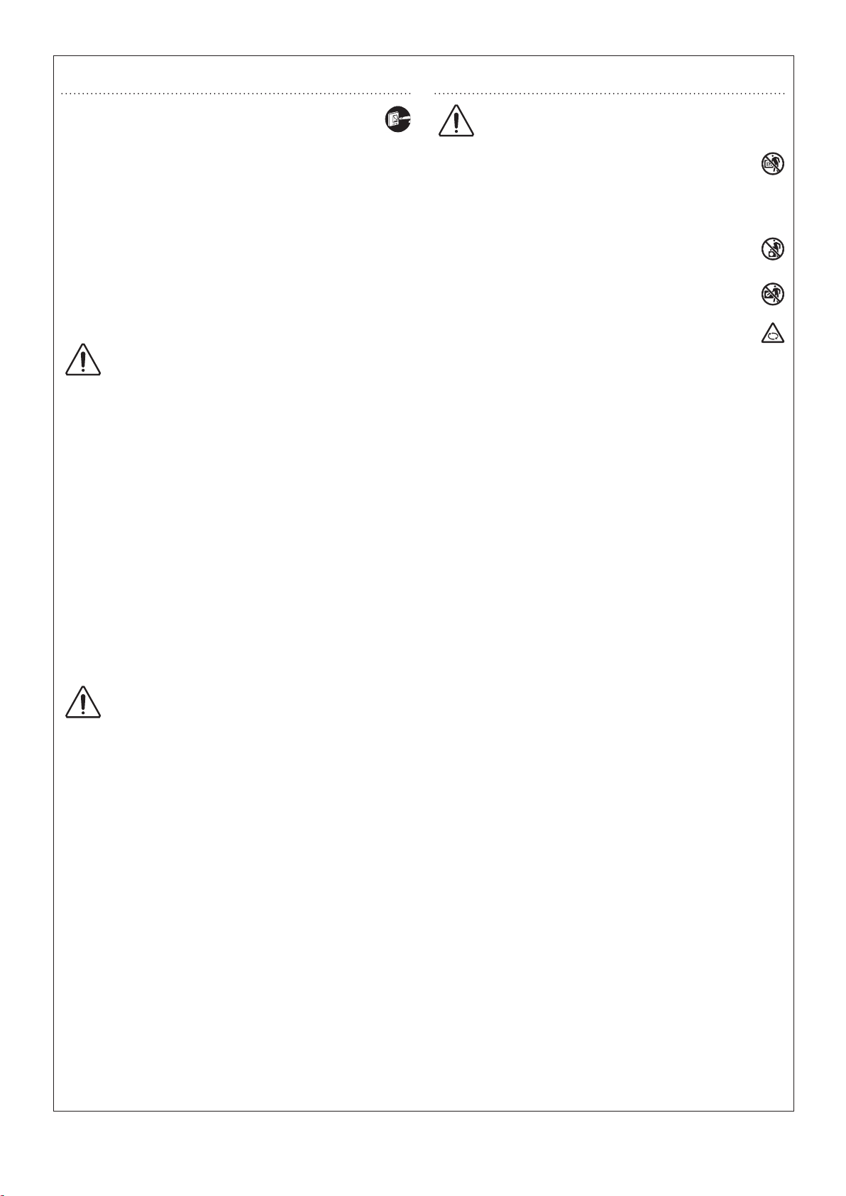
When Servicing
Others
• Turn the power OFF at the main
power box (mains), wait at least 10
minutes until it is discharged, then
open the unit to check or repair
electrical parts and wiring.
• Keep your fingers and clothing away
from any moving parts.
• Clean up the site after you finish,
remembering to check that no metal
scraps or bits of wiring have been left
inside the unit.
WARNING
• This product must not be
modified or disassembled under
any circumstances. Modified or
disassembled unit may cause fire,
electric shock or injury.
• Do not clean inside the indoor and
outdoor units by users. Engage
authorized dealer or specialist for
cleaning.
• In case of malfunction of this
appliance, do not repair by
yourself. Contact to the sales
dealer or service dealer for a
repair.
CAUTION
• Do not touch the air inlet or
the sharp aluminum fins of the
outdoor unit. You may get
injured.
• Do not sit or step on the unit,
you may fall down accidentally.
• Do not stick any object into the
FAN CASE.
You may be injured and the unit
may be damaged.
CAUTION
• Ventilate any enclosed areas when
installing or testing the refrigeration
system. Leaked refrigerant gas,
on contact with fire or heat, can
produce dangerously toxic gas.
• Confirm after installation that no
refrigerant gas is leaking. If the gas
comes in contact with a burning
stove, gas water heater, electric
room heater or other heat source,
it can cause the generation of toxic
gas.
iv
Page 6
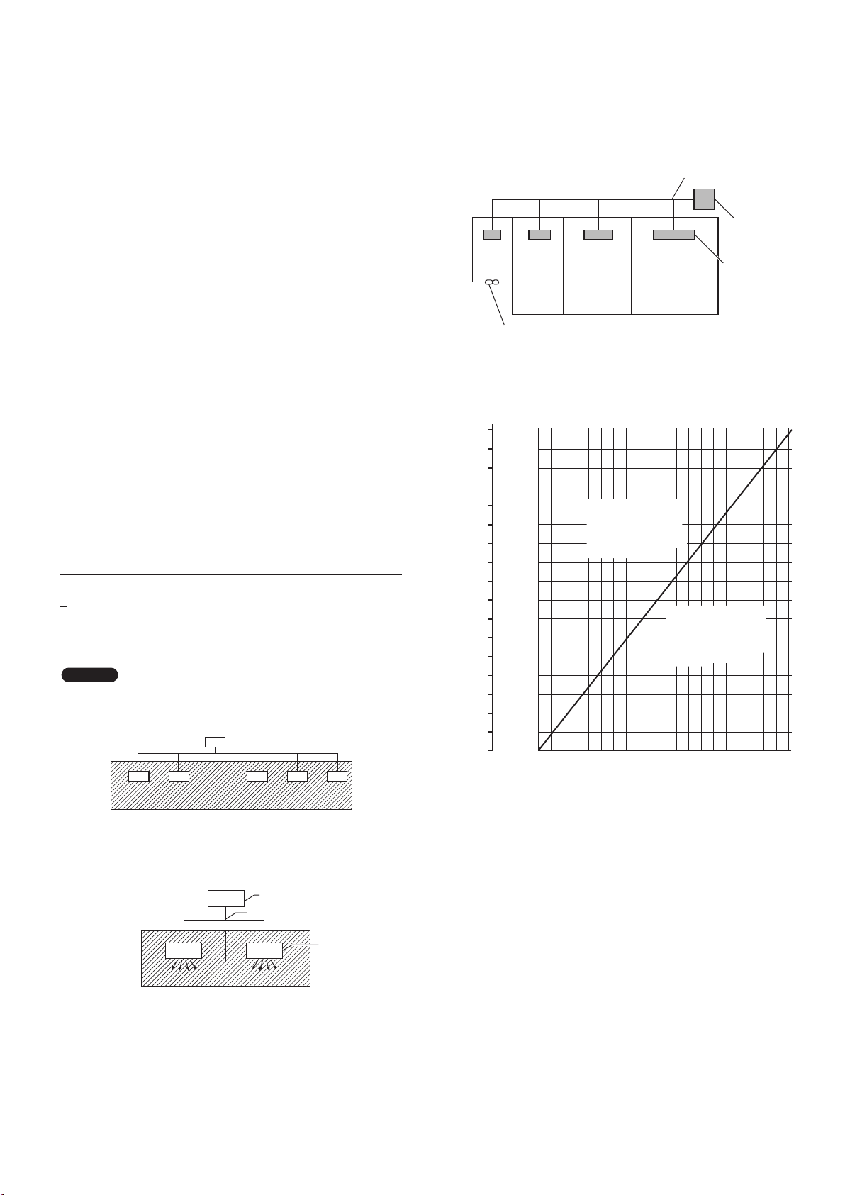
Check of Density Limit
Precautions for Installation Using New Refrigerant
1. Care regarding tubing
1-1. Process tubing
Material: Use seamless phosphorous deoxidized copper tube for refrigeration. Wall thickness shall comply with the applicable
legislation. The minimal wall thickness must be in accordance with the table below. For tubes of ø22.22 or larger, use the material of
temper 1/2H or H (Hard copper tube). Do not bend the hard copper tube.
Tubing size: Be sure to use the sizes indicated in the table below.
For the renewal tubing size, refer to the Technical Data.
Use a tube cutter when cutting the tubing, and be sure to remove any flash. This also applies to distribution joints (optional).
When bending tubing, use a bending radius that is 4 times the outer diameter of the tubing or larger.
CAUTION
Use sufficient care in handling the tubing. Seal the tubing ends with caps or tape to prevent dirt,
moisture, or other foreign substances from entering. These substances can result in system
malfunction.
Unit: mm
)ebut reppoc tfoS( O - repmeTlairetaM
Copper tube
Outer diameter 6.35 9.52 12.7 15.88 19.05
Wall thickness 0.8 0.8 0.8 1.0 1.2
Unit: mm
Material Temper - 1/2 H, H (Hard copper tube)
Copper tube
Outer diameter 22.22 25.4
Wall thickness 1.0 1.0
1-2. Prevent impurities including water, dust and oxide from entering the tubing. Impurities can cause R410A refrigerant deterioration
and compressor defects. Due to the features of the refrigerant and refrigerating machine oil, the prevention of water and other
impurities becomes more important than ever.
2. Be sure to recharge the refrigerant only in liquid form.
2-1. Since R410A is a non-azeotrope, recharging the refrigerant in gas form can lower performance and cause defects in the unit.
2-2. Since refrigerant composition changes and performance decreases when gas leaks, collect the remaining refrigerant and recharge
the required total amount of new refrigerant after fixing the leak.
3. Different tools required
3-1. Tool specifications have been changed due to the characteristics of R410A.
Some tools for R22- and R407C-type refrigerant systems cannot be used.
Item New tool?
R407C tools
compatible
with R410A?
Remarks
Manifold gauge
Manifold gauge Yes No Types of refrigerant, refrigerating machine oil,
and pressure gauge are different.
Charge hose Yes No To resist higher pressure, material must be
changed.
Vacuum pump Yes Yes Use a conventional vacuum pump if it is equipped
with a check valve. If it has no check valve,
purchase and attach a vacuum pump adapter.
Leak detector Yes No Leak detectors for CFC and HCFC that react to
chlorine do not function because R410A contains
no chlorine. Leak detectors for HFC134a can be
used for R410A.
Vacuum pump
Outlet
Inlet
Flaring oil Yes No For systems that use R22, apply mineral oil
(Suniso oil) to the flare nuts on the tubing to
prevent refrigerant leakage. For machines that
use R407C or R410A, apply synthetic oil (ether
oil) to the flare nuts.
* Using tools for R22 and R407C and new tools for R410A together can cause defects.
3-2. Use R410A exclusive cylinder only.
Single-outlet valve
(with siphon tube)
Liquid refrigerant should be
recharged with the cylinder
standing on end as shown.
Valve
Liquid
Check the amount of refrigerant in the system and
floor space of the room according to the legislation on
refrigerant drainage. If there is no applicable legislation,
follow the standards described below.
The room in which the air conditioner is to be installed
requires a design that in the event of refrigerant gas
leaking out, its density will not exceed a set limit.
The refrigerant (R410A), which is used in the air conditioner,
is safe, without the toxicity or combustibility of ammonia, and
is not restricted by laws imposed to protect the ozone layer.
However, since it contains more than air, it poses the risk of
suffocation if its density should rise excessively. Suffocation
from leakage of refrigerant is almost non-existent. With the
recent increase in the number of high density buildings,
however, the installation of multi air conditioner systems is
on the increase because of the need for effective use of floor
space, individual control, energy conservation by curtailing heat
and carrying power, etc.
Most importantly, the multi air conditioner system is able
to replenish a large amount of refrigerant compared to
conventional individual air conditioners. If a single unit of the
multi air conditioner system is to be installed in a small room,
select a suitable model and installation procedure so that if the
refrigerant accidentally leaks out, its density does not reach the
limit (and in the event of an emergency, measures can be made
before injury can occur).
In a room where the density may exceed the limit, create an
opening with adjacent rooms, or install mechanical ventilation
combined with a gas leak detection device. The density is as
given below.
Min. volume of the indoor unit installed room (m
< Density limit (kg/m
The density limit of refrigerant which is used in multi air
conditioners is 0.44 kg/m
Total amount of refrigerant (kg)
3
)
3
(ISO 5149).
3
)
NOTE
1. The standards for minimum room volume are as follows.
(1) No partition (shaded portion)
(3) If an indoor unit is installed in each partitioned room and
the refrigerant tubing is interconnected, the smallest room
of course becomes the object. But when mechanical
ventilation is installed interlocked with a gas leakage
detector in the smallest room where the density limit is
exceeded, the volume of the next smallest room becomes
the object.
Refrigerant tubing
Very
small
room
Small
room
Mechanical ventilation device – Gas leak detector
Medium
room
Large room
2. The minimum indoor floor space compared with the
amount of refrigerant is roughly as follows: (When the
ceiling is 2.7 m high)
3
2
m
m
229.5
85
80
216.0
75
202.5
70
189.0
65
175.5
60
162.0
55
148.5
50
135.0
45
121.5
40
108.0
35
94.5
30
81.0
Min. indoor volume
25
Min. indoor floor area
(when the ceiling is 2.7 m high)
67.5
20
54.0
40.5
15
10
27.0
5
13.5
0
0.0
Range below the
density limit of
0.44 kg/m³
(Countermeasures
not needed)
20100 30 40 60 70 80 90 10050
Total amount of refrigerant
Range above the
density limit of
0.44 kg/m³
(Countermeasures
needed)
Outdoor unit
Indoor unit
(2) When there is an effective opening with the adjacent room
for ventilation of leaking refrigerant gas (opening without
a door, or an opening 0.15% or larger than the respective
floor spaces at the top or bottom of the door).
Outdoor unit
Refrigerant tubing
Indoor unit
kg
v
Page 7
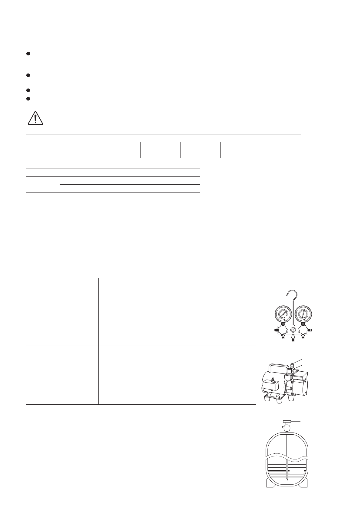
Precautions for Installation Using New Refrigerant
1. Care regarding tubing
1-1. Process tubing
Material: Use seamless phosphorous deoxidized copper tube for refrigeration. Wall thickness shall comply with the applicable
legislation. The minimal wall thickness must be in accordance with the table below. For tubes of ø22.22 or larger, use the material of
temper 1/2H or H (Hard copper tube). Do not bend the hard copper tube.
Tubing size: Be sure to use the sizes indicated in the table below.
For the renewal tubing size, refer to the Technical Data.
Use a tube cutter when cutting the tubing, and be sure to remove any flash. This also applies to distribution joints (optional).
When bending tubing, use a bending radius that is 4 times the outer diameter of the tubing or larger.
CAUTION
Copper tube
Copper tube
1-2. Prevent impurities including water, dust and oxide from entering the tubing. Impurities can cause R410A refrigerant deterioration
and compressor defects. Due to the features of the refrigerant and refrigerating machine oil, the prevention of water and other
impurities becomes more important than ever.
2. Be sure to recharge the refrigerant only in liquid form.
2-1. Since R410A is a non-azeotrope, recharging the refrigerant in gas form can lower performance and cause defects in the unit.
2-2. Since refrigerant composition changes and performance decreases when gas leaks, collect the remaining refrigerant and recharge
the required total amount of new refrigerant after fixing the leak.
3. Different tools required
3-1. Tool specifications have been changed due to the characteristics of R410A.
Some tools for R22- and R407C-type refrigerant systems cannot be used.
Item New tool?
Manifold gauge Yes No Types of refrigerant, refrigerating machine oil,
Charge hose Yes No To resist higher pressure, material must be
Vacuum pump Yes Yes Use a conventional vacuum pump if it is equipped
Leak detector Yes No Leak detectors for CFC and HCFC that react to
Flaring oil Yes No For systems that use R22, apply mineral oil
* Using tools for R22 and R407C and new tools for R410A together can cause defects.
3-2. Use R410A exclusive cylinder only.
Use sufficient care in handling the tubing. Seal the tubing ends with caps or tape to prevent dirt,
moisture, or other foreign substances from entering. These substances can result in system
malfunction.
Unit: mm
)ebut reppoc tfoS( O - repmeTlairetaM
Outer diameter 6.35 9.52 12.7 15.88 19.05
Wall thickness 0.8 0.8 0.8 1.0 1.2
Unit: mm
Material Temper - 1/2 H, H (Hard copper tube)
Outer diameter 22.22 25.4
Wall thickness 1.0 1.0
R407C tools
compatible
with R410A?
Remarks
and pressure gauge are different.
changed.
with a check valve. If it has no check valve,
purchase and attach a vacuum pump adapter.
chlorine do not function because R410A contains
no chlorine. Leak detectors for HFC134a can be
used for R410A.
(Suniso oil) to the flare nuts on the tubing to
prevent refrigerant leakage. For machines that
use R407C or R410A, apply synthetic oil (ether
oil) to the flare nuts.
Single-outlet valve
(with siphon tube)
Liquid refrigerant should be
recharged with the cylinder
standing on end as shown.
Manifold gauge
Vacuum pump
Outlet
Inlet
Valve
Liquid
vi
Page 8
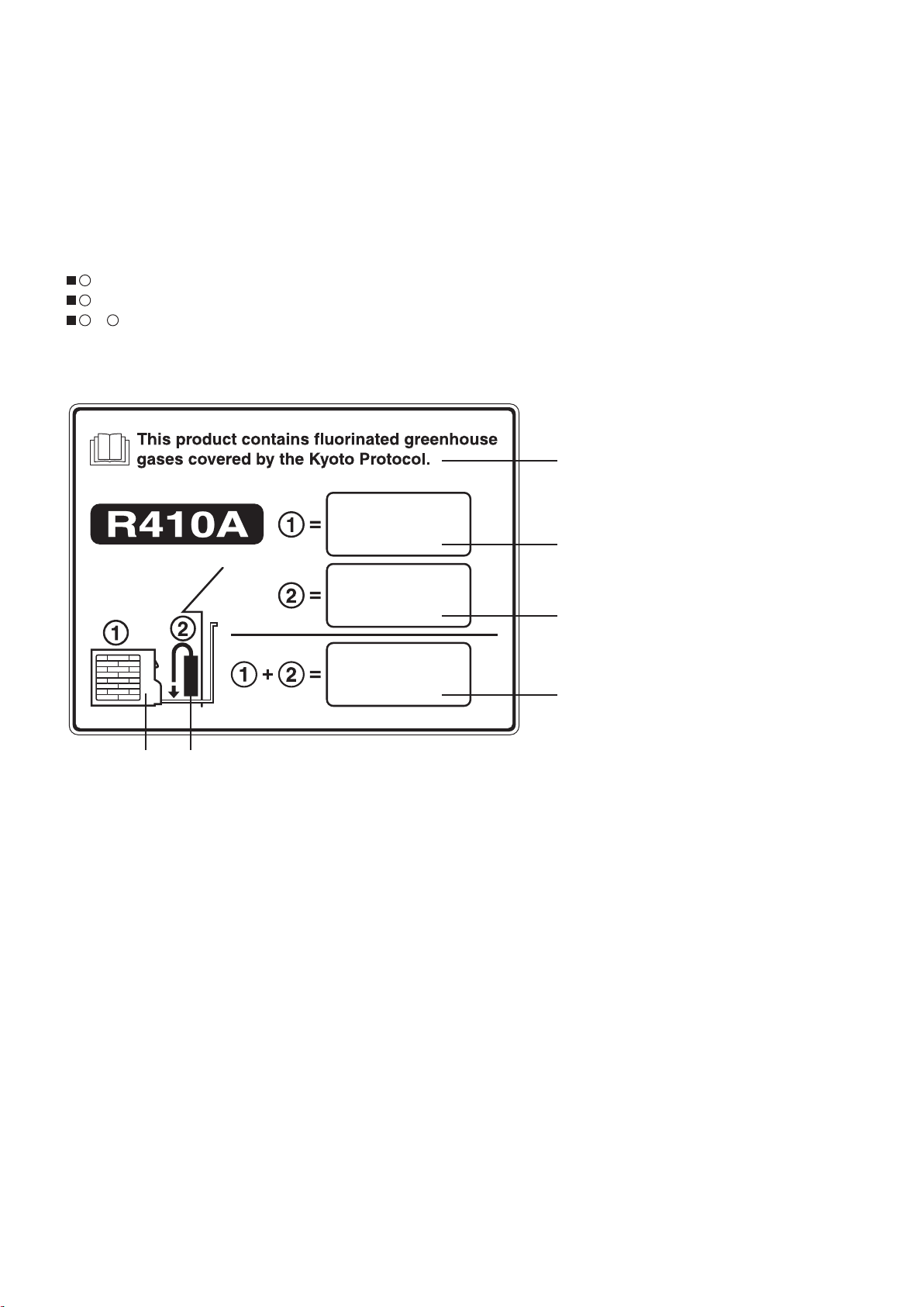
Important Information Regarding The Refrigerant Used
This product contains fluorinated greenhouse gases covered by the Kyoto Protocol. Do not vent gases into the atmosphere.
Refrigerant type: R410A
(1)
GWP
value: 1975
(1)
GWP = global warming potential
Periodical inspections for refrigerant leaks may be required depending on European or local legislation.
Please contact your local dealer for more information.
Please fill in with indelible ink,
1 the factory refrigerant charge of the product
the additional refrigerant amount charged in the field and
122
+ the total refrigerant charge
on the refrigerant charge label supplied with the product.
The filled out label must be adhered in the proximity of the product charging port (e.g. onto the inside of the service cover).
4
* English text printed on this label is original. Each
5 6
1. Factory refrigerant charge of the product: see unit name plate
2. Additional refrigerant amount charged in the field
3. Total refrigerant charge
4. Contains fluorinated greenhouse gases covered by the Kyoto Protocol
5. Outdoor unit
6. Refrigerant cylinder and manifold for charging
language label will be sealed on this original text.
kg
1
kg
2
kg
3
vii
Page 9

—
CONTENTS
—
Section 1: CONTROL FUNCTIONS - Outdoor Unit ............................. 1-1
1. Introduction ............................................................. 1-2
2. Compressor Control ...................................................... 1-3
3. Special Control .......................................................... 1-9
4. Outdoor Unit Fan Control .................................................. 1-11
5. Outdoor Unit CCU (command controller unit) Control ............................ 1-14
6. Oil Control ............................................................. 1-19
7. 4-Way Valve Adjustment Control ............................................ 1-21
8. Defrost Control ......................................................... 1-22
9. Demand Control ........................................................ 1-24
10. Other Functions ......................................................... 1-27
11. Detailed Settings in EEPROM of Outdoor Unit ................................. 1-29
12. Outdoor Unit Control PCB ................................................. 1-31
13. Electrical Data .......................................................... 1-36
Section 2: CONTROL FUNCTIONS - Indoor Unit .............................. 2-1
1. Room Temperature Control ................................................. 2-2
2. Heating Standby ......................................................... 2-4
3. Automatic Fan Speed Control ............................................... 2-5
4. Indoor Unit MOV Control ................................................... 2-6
5. Drain Pump Control ...................................................... 2-6
6. Automatic Heating / Cooling Control .......................................... 2-7
7. Discharge Air Temperature Control ........................................... 2-8
8. RAP Valve Kit Control ..................................................... 2-8
9. Automatic Flap Control .................................................... 2-9
10. Filter Sign .............................................................. 2-9
11. Fan Control during Dry Mode .............................................. 2-10
12. Ventilation Fan Output .................................................... 2-11
13. T10 Terminal ........................................................... 2-11
14. Parameter ............................................................. 2-12
Section 3: OUTDOOR UNIT REPAIR PROCEDURES ........................... 3-1
1. Removing Panels ......................................................... 3-2
2. Discharging Compressor Oil ................................................ 3-3
3. Recovering Refrigerant .................................................... 3-4
4. Checking for Leakage After Repair ........................................... 3-9
5. Evacuating System ...................................................... 3-10
6. Charging Compressor Oil ................................................. 3-11
7. Pumping Out Refrigerant from Outdoor Unit ................................... 3-15
8. Compressor ............................................................ 3-18
viii
Page 10

Section 4: OUTDOOR UNIT MAINTENANCE REMOTE CONTROLLER ............ 4-1
1. Overview ............................................................... 4-2
2. Functions ............................................................... 4-3
3. Ordinary Display Controls and Functions ...................................... 4-4
4. Monitoring Operations ..................................................... 4-9
5. Outdoor Unit Alarm History Monitor ......................................... 4-11
6. Mode Settings .......................................................... 4-12
Section 5: REMOTE CONTROLLER FUNCTIONS ............................. 5-1
1. Simple Settings Function ................................................... 5-2
2. Detailed Settings Function .................................................. 5-8
3. Remote Controller Servicing Functions ....................................... 5-21
Section 6: TROUBLE DIAGNOSIS .......................................... 6-1
1. Contents of Remote Controller Switch Alarm Display .............................6-2
2. Outdoor Unit Control Panel LED Display ......................................6-4
3. Mini VRF Alarm Codes .................................................... 6-5
4. Inspection and Characteristics of Parts ...................................... 6-21
5. Test Pin ............................................................... 6-24
6. Symptom: Thermostat in OFF continues or cycles OFF & ON too frequently .......... 6-25
Section 7: TEST RUN. . . . . . . . . . . . . . . . . . . . . . . . . . . . . . . . . . . . . . . . . . . . . . . . . . . . . 7-1
1. Preparing for Test Run .....................................................7-2
2. Test Run Procedure .......................................................7-3
3. Main Outdoor Unit P.C.Board Setting .......................................... 7-4
4. Auto Address Setting ...................................................... 7-7
5. Setting Test Run Remote Controller. . . . . . . . . . . . . . . . . . . . . . . . . . . . . . . . . . . . . . . . . . 7-15
6. Caution for Pump Down ................................................... 7-16
7. Self-Diagnosis Function Table and Contents of Alarm Display ..................... 7-16
ix
Page 11

Mini VRF SYSTEM
Contents
Control Functions - Outdoor unit
1. CONTROL FUNCTIONS - Outdoor unit
1. Introduction ........................................................... 1-2
2. Compressor Control .................................................... 1-3
3. Special Control ........................................................ 1-9
4. Outdoor Unit Fan Control ............................................... 1-11
5. Outdoor Unit CCU (command controller unit) Control ....................... 1-14
6. Oil Control ........................................................... 1-19
7. 4-Way Valve Adjustment Control ......................................... 1-21
8. Defrost Control ....................................................... 1-22
9. Demand Control ....................................................... 1-24
10. Other Functions ....................................................... 1-27
11. Detailed Settings in EEPROM of Outdoor Unit ..............................1-29
1
12. Outdoor Unit Control PCB ..............................................1-31
13. Electrical Data ........................................................1-36
1 - 1
Page 12
Mini VRF SYSTEM
2WAY VRF SYSTEM
Control Functions
3. Compressor Control
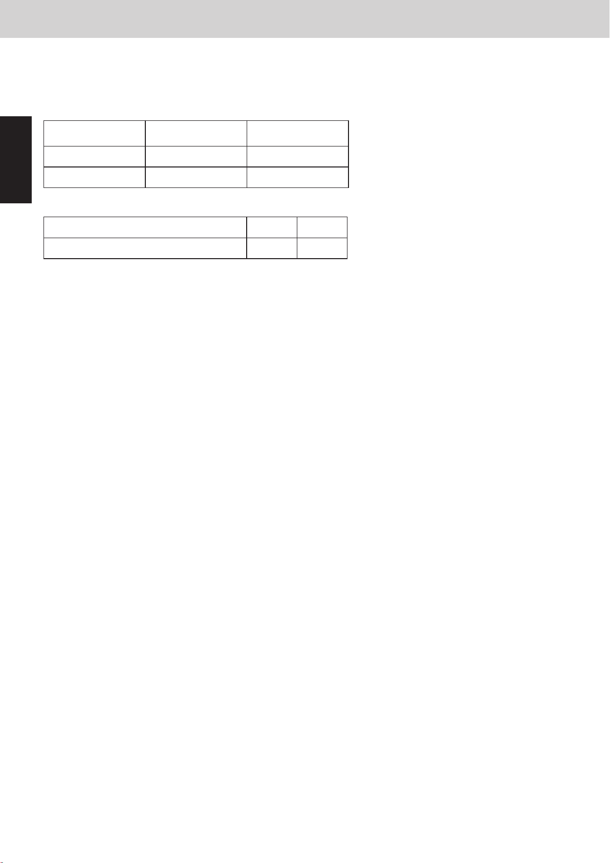
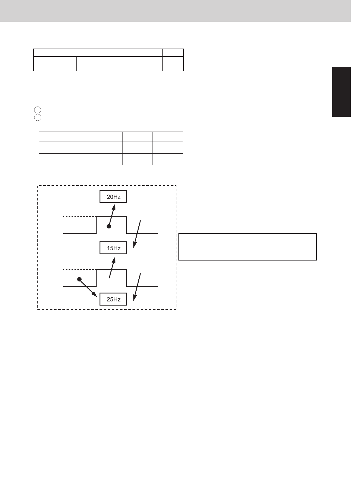
The inverter compressor can operate within the range in the table below.
When the high pressure is over 2.8MPa, the upper limit frequency is restricted.
The frequency range in the table above is subject to change without notice.*
*1 The minimum Hz changes according to the outdoor air temperature during cooling operation.
*2
・The upper limit frequency is sometimes restricted to 50Hz until the compressor gets warmer.
・During the oil recovery control among the systems or defrost control, the upper limit frequency is 60Hz.
・When operation started under the temperature of
10°C< outdoor air temperature ≤ 48°C, the
minimum Hz becomes 15Hz.
(2) Operating Frequency Range of Inverter Compressor
Type of outdoor unit
Minimum frequency (Hz) *1
Maximum frequency (Hz) *2 81.3
8HP 10HP
89.7
15 15
If the low pressure is over 1.6MPa during operation of the inverter compressor, the system is stopped.
(P27: Pre-trip)
1
2
48°C
43°C
20°C
10°C
1. Introduction
Mini VRF SYSTEM is a multi system that is connected to a single outdoor unit. The outdoor unit contains an inverter
compressor.
To operate this system, the below settings must be made at the time of the test run.
Table 1-1
At shipment
from factory
Settable range
1
Setting item
System address 1 System 1 – 30
No. of indoor units 1 1 – 15 units
Table 1-2
Control Functions - Outdoor unit
8 HP 10 HP
Maximum number of connected indoor units 15 15
Be sure to connect indoor units so that the resulting indoor-outdoor capacity ratio (total capacity of all indoor units
compared with the outdoor unit capacity) is within the range of 50% – 130%.
1 - 2
Page 13
Mini VRF SYSTEM
2WAY VRF SYSTEM
Control Functions
3. Compressor Control
2. Compressor Control
(1) Compressors Mounted in the Outdoor Units
Type of outdoor unit 8HP 10HP
Compressor 1
* The inverter compressor is operated according to the load and does not operate beyond outdoor unit capacity.
Inverter compressor
(High pressure rotary)
● ●
Control Functions - Outdoor unit
(2) Operating Frequency Range of Inverter Compressor
The inverter compressor can operate within the range in the table below.
1
When the high pressure is over 2.8MPa, the upper limit frequency is restricted.
If the low pressure is over 1.6MPa during operation of the inverter compressor, the system is stopped.
2
(P27: Pre-trip)
Type of outdoor unit
8HP 10HP
Minimum frequency (Hz) *1
Maximum frequency (Hz) *2 81.3
The frequency range in the table above is subject to change without notice.*
*1 The minimum Hz changes according to the outdoor air temperature during cooling operation.
48°C
43°C
15 15
89.7
・When operation started under the temperature of
10°C< outdoor air temperature ≤ 48°C, the
minimum Hz becomes 15Hz.
1
20°C
10°C
*2
・The upper limit frequency is sometimes restricted to 50Hz until the compressor gets warmer.
・During the oil recovery control among the systems or defrost control, the upper limit frequency is 60Hz.
1 - 3
Page 14

2. Compressor Control
2WAY VRF SYSTEM
Control Functions
3. Compressor Control
Compressor capacity can increase
6.5
Te_tgt_max.
Compressor capacity
cannot increase
Compressor capacity decreases
Max. load level
15
0
6.0
3.0
deg
2.5
Te_tgt_min.
6.0
3.0
16.0
unit: °C
13.0
30
11.0
8.0
Area B
Area C
Area A
Evaporation temperature area
3. Compressor Control
2WAY VRF SYSTEM
Control Functions
4-1. Evaporation temperature (= Te) control
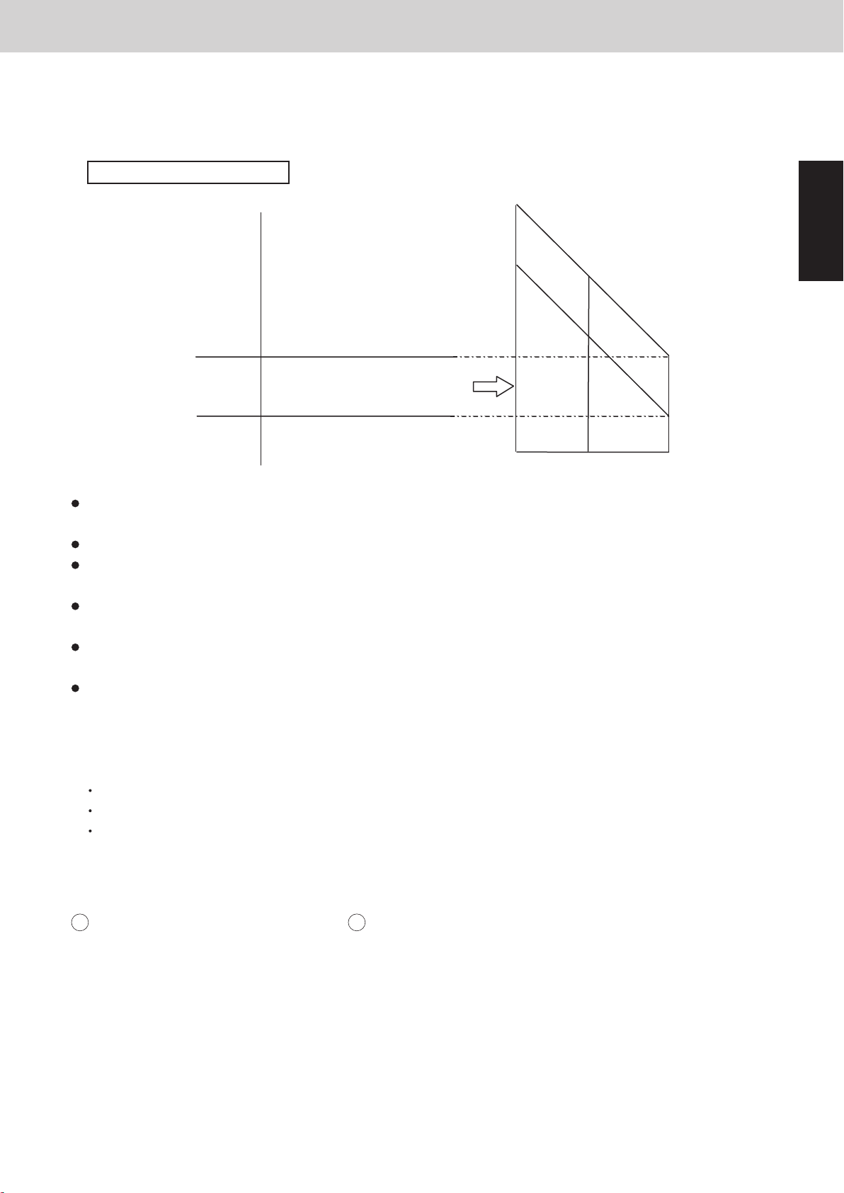
The cooling capacity is adjusted with this control. It prevents freezing of the indoor unit heat
exchanger and the dew to the outside panel of the indoor unit. The capacity is adjusted according
to the following figure.
If the test run is continued for a long time, the mist may occur but it is not abnormal.*
If more than 1 indoor unit is in test run mode, the evaporation temperature control is not applicable.
Once the indoor unit is selected for the test run, the thermostat will not be turned OFF.
After the last indoor unit is operated in the test run mode, the test run is automatically cancelled
after 1 hour.
4-2. Condensation Temperature Control
Target temperature of the Area B is different between cooling and heating operation.
In Cooling Mode
The purpose of this control at cooling
is to prevent abnormal high-pressure.
1
The evaporation temperature area changes depending on the maximum load level in each indoor
unit as shown on previous page.
The Area C is regarded as Area B for 6 minutes after compressor starts.
Test run mode in cooling operation is used when the room temperature is low and the indoor unit
thermostat is not turn ON. This mode is used for operation check when the outdoor unit is fully
operated or additional refrigerant charge without stopping the system.
When the system operates in a minimum capacity, the system will continue operating for at least
6 minutes if the evaporation temperature area is Area C.
During special controls such as defrosting or oil recovering between the systems, the compressor
capacity will not be controlled by the evaporation temperature control area.
If the outdoor unit is stopped while the evaporation temperature is in Area C, the system may
operate from the lower compressor capacity when starting next time.
Test run mode
In Heating Mode
Heating capacity is adjusted with this control.
It also prevents abnormal high-pressure simultaneously.
The capacity is controlled in the following diagram.
2
Mini VRF SYSTEM
Control Functions - Outdoor unit
(3) Forced Stopping of Compressor
1
Once a compressor stops, it will not start for a period of 3 minutes (3-minute forced OFF).
However, this is not applied when the compressor was forced to stop as the result of a special control
operation. (Start control, Defrost control, Refrigerant oil recovery control, etc.)
(4) Horsepower Control (Roadmap Control)
1
Horsepower control (start & stop of compressor and increase & decrease of inverter frequency) are
controlled according to the numerical value of the pressure sensor installed at the outdoor unit and the
temperature sensor installed at the indoor unit heat exchanger.
* The pressure detected by the pressure sensor is converted to the saturated temperature.
There are two types of controls; one is the pressure detected by the pressure sensor and the other is
detected by the saturated temperature.
High pressure saturated temperature is converted from values detected by the high pressure sensor.
Low pressure saturated temperature is converted from values detected by the low pressure sensor.
This control is performed every 30 seconds.
2
When cooling operation, evaporation temperature (= antifreeze control) and condensation temperature
3
(= high pressure prevention control) are applied.
When heating operation, condensation temperature (= high pressure prevention control) is applied.
Definition of evaporation temperature (Te)
Lowest temperature of all indoor units’ evaporation temperature (E1, E3) in the system including the
stopped indoor units
Definition of condensation temperature (Tc)
Outdoor units’ high pressure saturated temperature
Load level varies from a minimum of 0 to a maximum of 30 on 1 to 1 basis up to 31 levels.
When the indoor unit stops (including thermostat OFF), the level shows “0”.
In the case of test run mode, the actual level implies “30” even if a PC monitor indicates “31”.
* In the case that the compressor is stopped from such as special controls, load level does not turn to “0”
even if the indoor unit is most likely to be in stopped state.
The indoor unit demand level varies according to the following 2 conditions.
Intake temperature difference:
Difference between indoor unit remote control set temperature and intake temperature (TA)
Discharge temperature difference:
Difference between preset discharge setting temperature according to the type of indoor unit and
actual discharge temperature (TF)
Load level increases when the differential temperature noted above indicates plus (+) value and
decreases when it indicates minus (-) value.
However, the types of units which are set to control the discharge temperature vary according to the
lowest value from the intake temperature difference and discharge temperature difference.
Horsepower is controlled by the maximum value of all indoor units load level.
1 - 4
Page 15
2. Compressor Control
3. Compressor Control
2WAY VRF SYSTEM
Control Functions
Mini VRF SYSTEM
Control Functions - Outdoor unit
4-1. Evaporation temperature (= Te) control
The cooling capacity is adjusted with this control. It prevents freezing of the indoor unit heat
exchanger and the dew to the outside panel of the indoor unit. The capacity is adjusted according
to the following figure.
Evaporation temperature area
deg
Compressor capacity can increase
6.5
Te_tgt_max.
Te_tgt_min.
The evaporation temperature area changes depending on the maximum load level in each indoor
unit as shown on previous page.
The Area C is regarded as Area B for 6 minutes after compressor starts.
When the system operates in a minimum capacity, the system will continue operating for at least
6 minutes if the evaporation temperature area is Area C.
During special controls such as defrosting or oil recovering between the systems, the compressor
capacity will not be controlled by the evaporation temperature control area.
If the outdoor unit is stopped while the evaporation temperature is in Area C, the system may
operate from the lower compressor capacity when starting next time.
Test run mode
Test run mode in cooling operation is used when the room temperature is low and the indoor unit
thermostat is not turn ON. This mode is used for operation check when the outdoor unit is fully
operated or additional refrigerant charge without stopping the system.
If the test run is continued for a long time, the mist may occur but it is not abnormal.*
If more than 1 indoor unit is in test run mode, the evaporation temperature control is not applicable.
Once the indoor unit is selected for the test run, the thermostat will not be turned OFF.
After the last indoor unit is operated in the test run mode, the test run is automatically cancelled
after 1 hour.
6.0
3.0
2.5
Area A
Compressor capacity
cannot increase
Compressor capacity decreases
Area B
Area C
16.0
13.0
8.0
0
Max. load level
unit: °C
11.0
6.0
3.0
15
30
1
4-2. Condensation Temperature Control
Target temperature of the Area B is different between cooling and heating operation.
In Cooling Mode
1
The purpose of this control at cooling
is to prevent abnormal high-pressure.
In Heating Mode
2
Heating capacity is adjusted with this control.
It also prevents abnormal high-pressure simultaneously.
The capacity is controlled in the following diagram.
1 - 5
Page 16
2. Compressor Control
2WAY VRF SYSTEM
Control Functions
3. Compressor Control
3. Compressor Control
2WAY VRF SYSTEM
Control Functions
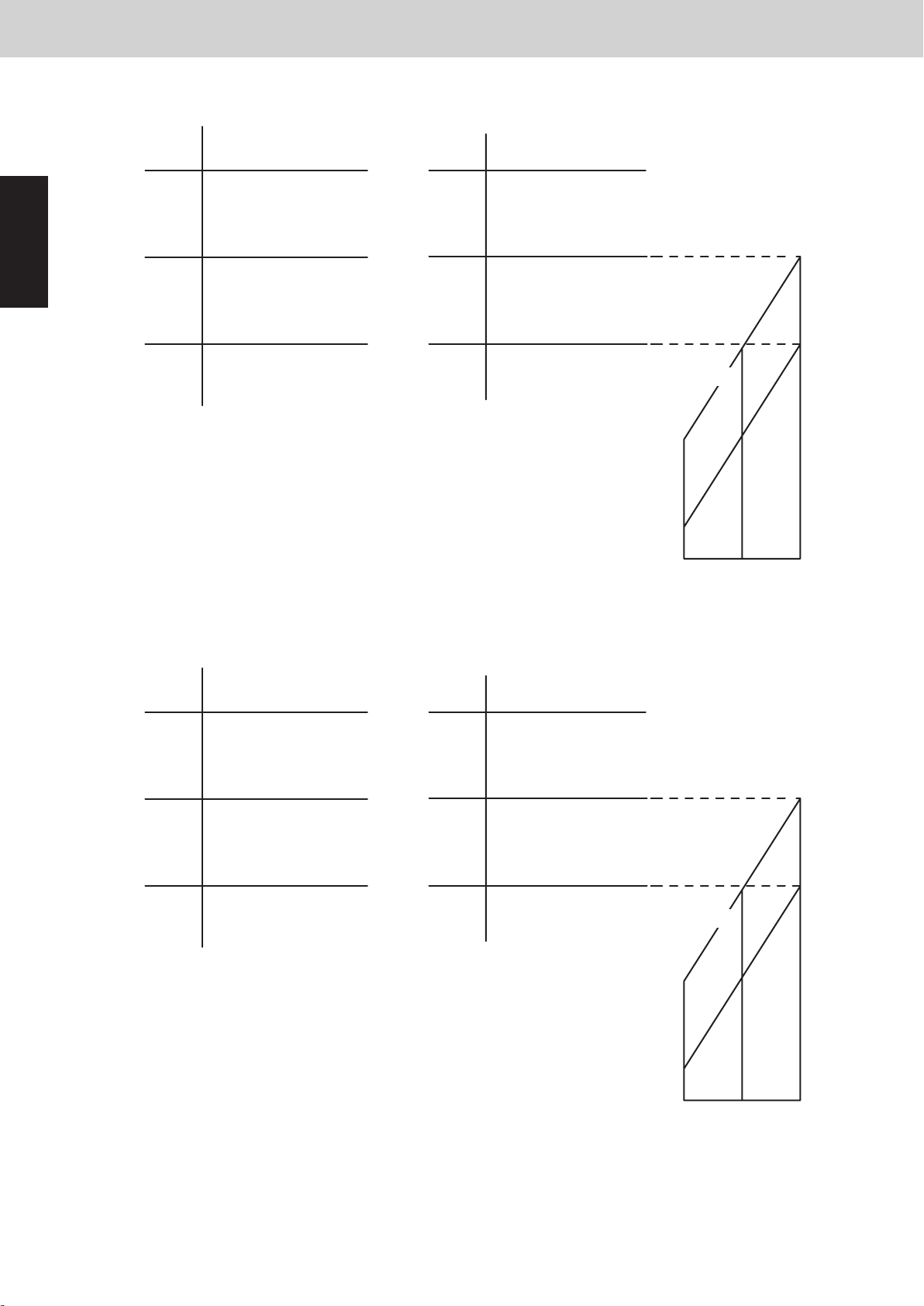
* Discharge temperature that is used for this control is the highest temperature among all compressors.
When the temperature falls in the Area D (over PX temperature), the operation stops within 0 to
30 seconds at the interval of the roadmap control.
After Tc falls in the Area D and the thermostat is turned OFF, the system may resume operating
from the lower compressor capacity.
Test Run
Test run mode in heating operation is used when the room temperature is high and the indoor unit
thermostat is not turned ON. This mode is used for operation check when the outdoor unit is fully
operated or additional refrigerant charge without stopping the system.
When the system operates in a minimum capacity, the system will continue operating for at least
6 minutes if the condensation temperature area is the Area C.
If it maintains in the Area C, the thermostat may turn OFF.
Once the indoor unit is selected for the test run, the thermostat will not be turned OFF.
However, condensation temperature control is performed in order to prevent the high load
according to the figure shown on previous page.
After the last indoor unit is operated in the test run mode, the test run is automatically cancelled
after 1 hour.
4-3. Protection Control
Compressor stops
Horsepower decreases
Horsepower cannot increase
Horsepower can increase
Capacity goes down 2.0HP
Capacity goes down 1.0HP
Capacity goes down 0.5HP
Compressor discharge temperature protection
The compressor capacity is controlled according to the figure below.
1
Low pressure protection control
In order to prevent the excessive decrease of low pressure, the compressor capacity is controlled
according to the figure below.
2
106
105
104
100
Capacity goes down 0.3HP
96
94
°C
No restriction
Capacity goes up slowly
0.25
0.20
Capacity cannot increase
Capacity goes down
H06 trip (Continuous for 2 minutes)
0.17
0.06
H06 trip0.02
Low pressure
MPa
Mini VRF SYSTEM
Control Functions - Outdoor unit
・Standard setting (at the shipment)
1
°C °C
PX=58.0 PX=58.0
57.9
55.1
55.0
53.0
52.9
Thermostat
OFF
Horsepower
decrease
Horsepower
increase
prohibited
Horsepower
increase
possible
Area D
Area C
Area B
Area A
57.9
50.1
50.0
48.0
47.9
Thermostat
OFF
Horsepower
decrease
Horsepower
increase
prohibited
Horsepower
increase
possible
Area D
Area C
Area B
Area A
42.0
34.0
33.0
40.5
°C
50.0
48.0
・Renewal setting (JP001 cut on all outdoor unit PCB) * For details, see Section 9 of Technical Data.
52.5
PX=
52.5-0.1
49.1
49.0
47.0
46.9
°C °C
Thermostat
OFF
Horsepower
decrease
Horsepower
increase
prohibited
Horsepower
increase
possible
Area D
Area C
Area B
Area A
52.5
PX=
52.5-0.1
48.1
48.0
47.0
46.9
Thermostat
OFF
Horsepower
decrease
Horsepower
increase
prohibited
Horsepower
increase
possible
Area D
Area C
Area B
Area A
Max. required level
33.5
32.5
15 300
40.5
39.5
°C
48.0
47.0
1 - 6
15 300
Max. required level
Page 17
2. Compressor Control
3. Compressor Control
2WAY VRF SYSTEM
Control Functions
Mini VRF SYSTEM
Control Functions - Outdoor unit
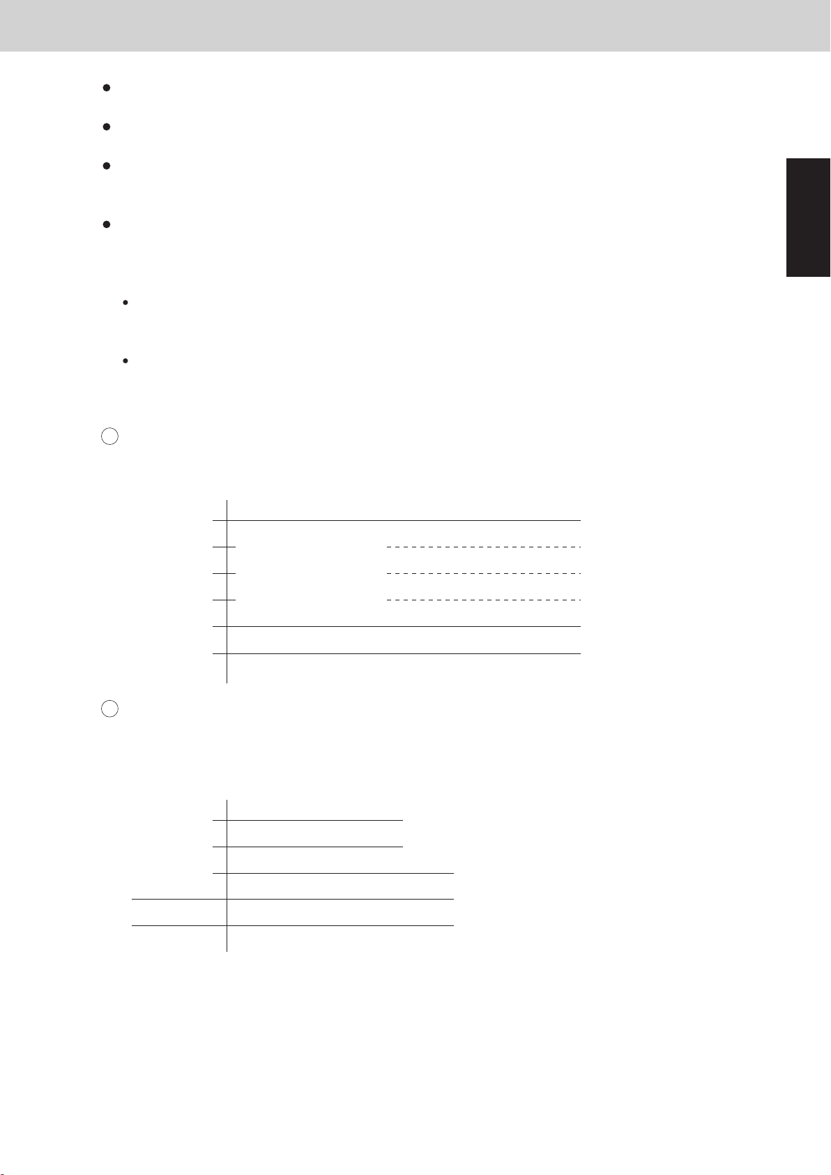
When the temperature falls in the Area D (over PX temperature), the operation stops within 0 to
30 seconds at the interval of the roadmap control.
After Tc falls in the Area D and the thermostat is turned OFF, the system may resume operating
from the lower compressor capacity.
When the system operates in a minimum capacity, the system will continue operating for at least
6 minutes if the condensation temperature area is the Area C.
If it maintains in the Area C, the thermostat may turn OFF.
Test Run
Test run mode in heating operation is used when the room temperature is high and the indoor unit
thermostat is not turned ON. This mode is used for operation check when the outdoor unit is fully
operated or additional refrigerant charge without stopping the system.
Once the indoor unit is selected for the test run, the thermostat will not be turned OFF.
However, condensation temperature control is performed in order to prevent the high load
according to the figure shown on previous page.
After the last indoor unit is operated in the test run mode, the test run is automatically cancelled
after 1 hour.
4-3. Protection Control
Compressor discharge temperature protection
1
The compressor capacity is controlled according to the figure below.
* Discharge temperature that is used for this control is the highest temperature among all compressors.
°C
106
105
104
100
Compressor stops
Horsepower decreases
96
Horsepower cannot increase
94
Horsepower can increase
1
Capacity goes down 2.0HP
Capacity goes down 1.0HP
Capacity goes down 0.5HP
Capacity goes down 0.3HP
Low pressure protection control
2
In order to prevent the excessive decrease of low pressure, the compressor capacity is controlled
according to the figure below.
Low pressure
MPa
0.25
0.20
0.17
0.06
No restriction
Capacity goes up slowly
Capacity cannot increase
Capacity goes down
H06 trip (Continuous for 2 minutes)
H06 trip0.02
1 - 7
Page 18
2. Compressor Control
4. Special Control
2WAY VRF SYSTEM
Control Functions
Items Remarks Indication on PCB
This valve turns OFF at cooling mode, and turns ON at heating mode.
When the outdoor unit stops, the 4-way valve maintains in the same state as before.
Regarding the operation in defrost mode, see the section "8. Defrost Control".
Solenoid valve
Motor Operated Valve
Crankcase heater
4-way valve
Oil recovery valve
O
2 valve
MOV for heat exchanger 1
MOV for heat exchanger 2
Crankcase heater
20S
ORVR
O
2
MOV1
MOV2
CH
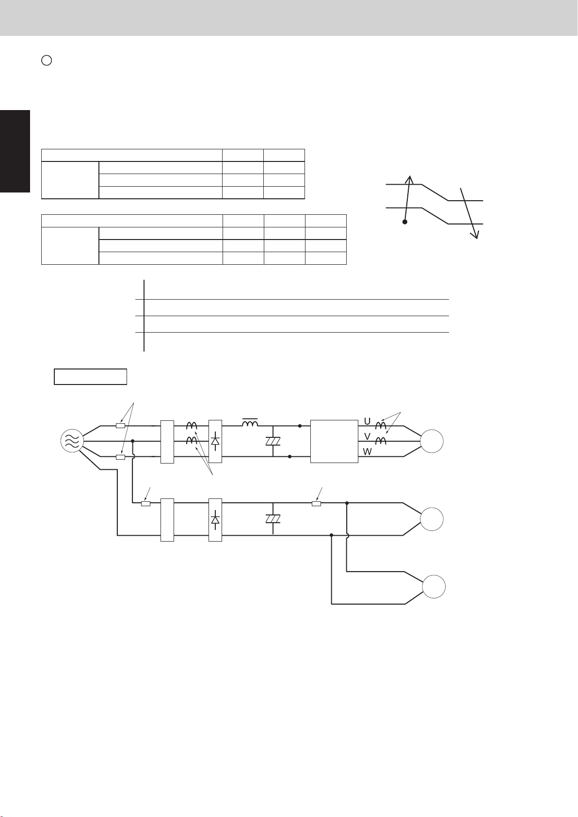
(1) 4-way Valve [20S]
This valve turns ON for 5 seconds before the inverter compressor starts. After the inverter compressor starts, the
valve is ON for 2 minutes. After that, it turns OFF.
SAVE valve
5 seconds 2 minutes
Inverter compressor starts
Compressor
Valve turns ON
α
β
3.00
MPa
2.90
3.42
Renewal
setting
Standard
setting
3.32
Valve turns OFF
This valve turns ON for 30 seconds after the outdoor unit stops. After that, it turns OFF.
This valve turns ON when the high pressure sensor detects α to prevent
abnormal pressure shown in the table at right.
This valve turns OFF when the high pressure goes down below β shown
in the table at right.
This valve turns ON when the high pressure switch is activated.
This valve stays ON for 10 seconds after the high pressure switch returns in normal.
After that, it turns OFF.
This valve might turn ON when the system capacity is excessive although the inverter compressor operates at
minimum frequency.
This valve turns ON while the discharge temperature of the compressor is low.
This valve turns ON during the operation of 4-way valve control.
(2) Oil Recovery Valve [ORVR]
The purpose of this valve is to recover oil from the oil separator to the compressor and is to adjust the
capacity and pressure.
This valve turns ON when the oil level of the compressor is “0” or “1”.
This valve is always OFF when outdoor unit is stopped.
* For oil level of compressor, see the section “6. Oil Control”.
Current protection
3
This restriction protects the compressor and controls the compressor electric current simultaneously.
The current limitation value changes to “normal status” and “overload status” according to the outdoor
temperature.
The primary and secondary current values of the inverter compressors are measured.
unit: Ampere
1
Primary
Secondary
Type of outdoor unit 8HP 10HP
Limit current 1 15.4 21.4
Maximum current 1 H 12.4 18.4
Maximum current 1 L 11.4 17.4
Common 8HP and 10HP (1) (2) (3)
Limit current 2 24.3 24.3 24.3
Maximum current 2 H 21.8 20.0 18.0
Maximum current 2 L 20.8 19.0 17.0
Mini VRF SYSTEM
Control Functions - Outdoor unit
Outdoor air
temperature
Over
40 °C
Over
36 °C
(3)
(2)
(1)
Less than
39 °C
Less than
35 °C
Limit current 1, 2
Max. current 1H, 2H
Max. current 1L, 2L
Inverter layout
Power
supply
L1
L2
L3
N
Stop If this current is detected at regular intervals, alarm appears.
Frequency of inverter compressor goes down.
Frequency of inverter compressor cannot increase.
Frequency of inverter compressor can increase.
FuseFuse
Noise filter
Fuse
Noise filter
Primary CT1
Reactor
Diode
bridge
Diode
bridge
IPM
(CM1)
Fuse
Secondary CT
Compressor
Fan motor 1
Fan motor 2
1 - 8
Page 19
3. Special Control
4. Special Control
2WAY VRF SYSTEM
Control Functions
Mini VRF SYSTEM
Control Functions - Outdoor unit
Items Remarks Indication on PCB
Solenoid valve
Motor Operated Valve
Crankcase heater
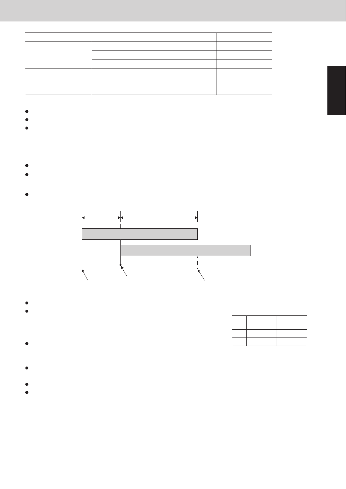
(1) 4-way Valve [20S]
This valve turns OFF at cooling mode, and turns ON at heating mode.
Regarding the operation in defrost mode, see the section "8. Defrost Control".
When the outdoor unit stops, the 4-way valve maintains in the same state as before.
(2) Oil Recovery Valve [ORVR]
The purpose of this valve is to recover oil from the oil separator to the compressor and is to adjust the
capacity and pressure.
This valve is always OFF when outdoor unit is stopped.
This valve turns ON when the oil level of the compressor is “0” or “1”.
* For oil level of compressor, see the section “6. Oil Control”.
This valve turns ON for 5 seconds before the inverter compressor starts. After the inverter compressor starts, the
valve is ON for 2 minutes. After that, it turns OFF.
4-way valve
Oil recovery valve
2 valve
O
MOV for heat exchanger 1
MOV for heat exchanger 2
Crankcase heater
5 seconds 2 minutes
20S
ORVR
MOV1
MOV2
O
2
CH
1
SAVE valve
Compressor
Inverter compressor starts
Valve turns ON
This valve turns ON for 30 seconds after the outdoor unit stops. After that, it turns OFF.
This valve turns ON when the high pressure sensor detects α to prevent
abnormal pressure shown in the table at right.
This valve turns OFF when the high pressure goes down below β shown
in the table at right.
This valve turns ON when the high pressure switch is activated.
This valve stays ON for 10 seconds after the high pressure switch returns in normal.
After that, it turns OFF.
This valve might turn ON when the system capacity is excessive although the inverter compressor operates at
minimum frequency.
This valve turns ON while the discharge temperature of the compressor is low.
This valve turns ON during the operation of 4-way valve control.
Valve turns OFF
α
β
Standard
setting
3.42
3.32
MPa
Renewal
setting
3.00
2.90
1 - 9
Page 20
3. Special Control
2WAY VRF SYSTEM
Control Functions
4. Special Control
5. Outdoor Unit Fan Control
2WAY VRF SYSTEM
Control Functions
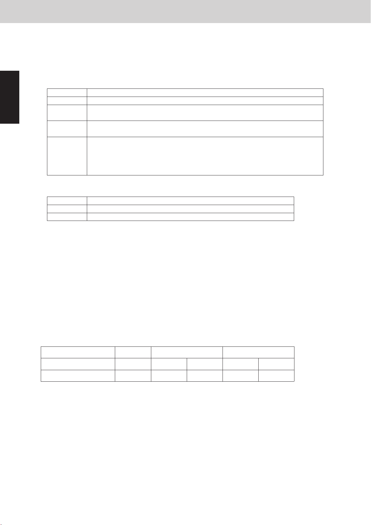
(1) Number of Fan Motor
These outdoor units utilize a DC fan motor that can be controlled in 0〜15 steps (0〜15 modes) in ordinary mode.
The control range is expanded to a maximum of 15 steps (15 modes) if high static-pressure mode has been set.
The fan rotating numbers will be changed according to the fan steps.
(2) Fan Step
3-1. Maximum rotation number of fan
3-2. Minimum rotation number of fan
Maximum rotation number of fan is limited regardless of the fan step as shown below.
Minimum rotation number in fan step is limited by the secondary current value and ambient temperature as
shown in the table below.
A mode that has higher number of revolutions than that written in the table below becomes the minimum fan
step.
The rotation number of fan can be taken priority rather than silent mode.
Ambient temperature (AT)
(3) Minimum Fan Step and Maximam Fan Step
AT < 0°C 40°C ≤ AT
SC > 17.0A
Secondary
Current
(SC)
0°C ≤ AT
< 10°C
12.0A < SC ≤ 17.0A
7.0A < SC ≤ 12.0A
SC ≤ 7.0A
350rpm
250rpm
160rpm
0rpm
450rpm
350rpm
160rpm
0rpm
550rpm
400rpm
250rpm
100rpm
650rpm
500rpm
250rpm
140rpm
700rpm
600rpm
350rpm
150rpm
800rpm
700rpm
400rpm
150rpm
10°C ≤ AT
< 20°C
20°C ≤ AT
< 30°C
30°C ≤ AT
< 40°C
Type of outdoor unit
Number of fan motor
8・10HP
2
Type of outdoor unit
8・10HP
Cooling mode
Heating mode
8HP 10HP
850rpm (step14)
900rpm (step15)
800rpm (step13)
850rpm (step14)
Mini VRF SYSTEM
Control Functions - Outdoor unit
(3) O2 Valve [O2] *O2 valve is the local supply parts.
This valve works when the outdoor unit receives signal of the refrigerant leakage from the indoor unit.
The indoor unit that transmits the signal of the refrigerant leakage gives “P14”alarm.
To activate this function, it is necessary to set it to EEPROM on the main outdoor PCB and indoor PCB.
EEPROM setting in main outdoor unit
CODE: C1
1
(4) Electronic Control Valves [MOV1, MOV2]
4-1. Type of Electronic control valves
Setting No.
0
1
EEPROM setting in indoor unit
CODE: 0B
Both MOV1 and MOV2 are controlled by the same pulse.
2
3
Setting No.
0
1
This function invalid (factory preset mode)
This valve is turned OFF when the system is normal.
This valve is turned ON when the outdoor unit receives signal from the indoor unit
This valve is turned ON when the system is normal.
This valve is turned OFF when the outdoor unit receives signal from the indoor unit
This valve is turned OFF when the system is normal.
This valve is turned ON and performs pump down control when the outdoor unit
receives signal from the indoor unit.
It is necessary to install the external refrigerant recovery circuit in order to make this
setting. (field supply)
Function of EXCT plug short-circuit
Indoor unit does thermostat OFF
Indoor unit gives “P14”alarm and transmits the refrigerant leakage signal.
(factory preset mode)
4-2. Power Initialization
If no indoor units have started (even once) after the power supply to the outdoor unit, the MOV holds the 480
pulses (fully open).
*When the indoor unit receives the signal for operation request from the control equipment, the pulse turns
other than the 480 pulses (regardless of the thermostat ON/OFF or operating ON/OFF).
It is necessary to switch ON the power supply again if the 480 pulses are required.
4-3. Control of Electronic control valves
(5) Crankcase Heater Control [CH]
Electronic control valves for heat exchanger control according to the operation mode.
MOV1 and MOV2 (pulse)
*1 However, 100 pulses remain for 2 minutes after unit stopped.
*2 When the outdoor unit stops and low pressure ≤ 0.16 MPa, 60 pulses remain for 30 seconds.
*3 If any one compressor in the outdoor unit is operating in heating mode, electronic control valves perform SH
control.
SH control adjusts the difference of temperature between the liquid and gas temperature to -1 ~ 5 degrees
Celsius.
When the compressor stops, the crankcase heater of its own compressor is turned ON / OFF in the following
conditions.
●
When the outdoor air temperature < 25°C :ON
●
When the outdoor air temperature ≥ 27°C : OFF
Compressor
Stop
Stop
0
Stop
1
0*
Cooling HeatingMode of system
Operation
480
Stop
2
0*
Operation
0 ~ 480*
3
1 - 10
Page 21

4. Outdoor Unit Fan Control
5. Outdoor Unit Fan Control
2WAY VRF SYSTEM
Control Functions
Mini VRF SYSTEM
Control Functions - Outdoor unit
(1) Number of Fan Motor
Type of outdoor unit
Number of fan motor
(2) Fan Step
These outdoor units utilize a DC fan motor that can be controlled in 0〜15 steps (0〜15 modes) in ordinary mode.
The control range is expanded to a maximum of 15 steps (15 modes) if high static-pressure mode has been set.
The fan rotating numbers will be changed according to the fan steps.
(3) Minimum Fan Step and Maximam Fan Step
3-1. Maximum rotation number of fan
Maximum rotation number of fan is limited regardless of the fan step as shown below.
Type of outdoor unit
Cooling mode
Heating mode
3-2. Minimum rotation number of fan
Minimum rotation number in fan step is limited by the secondary current value and ambient temperature as
shown in the table below.
A mode that has higher number of revolutions than that written in the table below becomes the minimum fan
step.
The rotation number of fan can be taken priority rather than silent mode.
8・10HP
2
8HP 10HP
800rpm (step13)
850rpm (step14)
850rpm (step14)
900rpm (step15)
1
Secondary
Current
(SC)
8・10HP
SC > 17.0A
12.0A < SC ≤ 17.0A
7.0A < SC ≤ 12.0A
SC ≤ 7.0A
Ambient temperature (AT)
AT < 0°C 40°C ≤ AT
350rpm
250rpm
160rpm
0rpm
0°C ≤ AT
< 10°C
450rpm
350rpm
160rpm
0rpm
10°C ≤ AT
< 20°C
550rpm
400rpm
250rpm
100rpm
20°C ≤ AT
< 30°C
650rpm
500rpm
250rpm
140rpm
30°C ≤ AT
< 40°C
700rpm
600rpm
350rpm
150rpm
800rpm
700rpm
400rpm
150rpm
1 - 11
Page 22
4. Outdoor Unit Fan Control
2WAY VRF SYSTEM
Control Functions
5. Outdoor Unit Fan Control
5. Outdoor Unit Fan Control
2WAY VRF SYSTEM
Control Functions
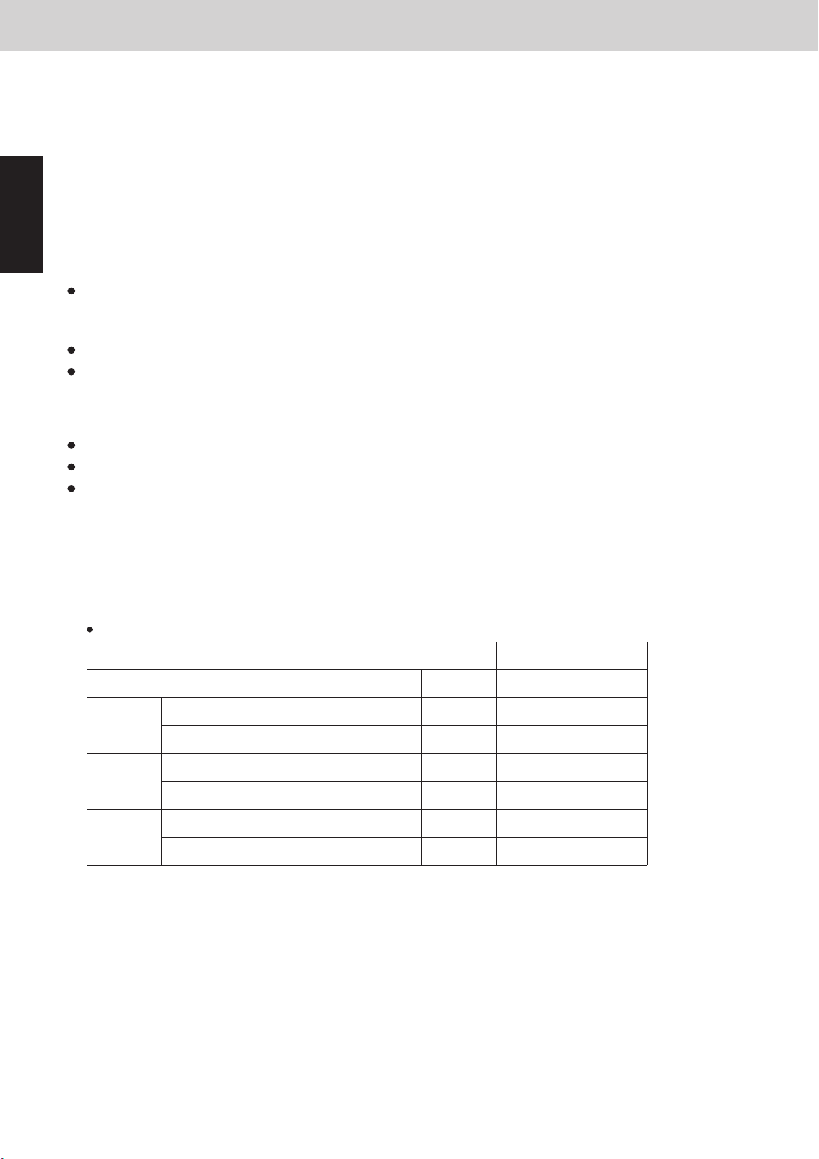
The system entirely becomes to the silent mode by setting in the main outdoor unit.
EEPROM setting in main outdoor unit
CODE : 05
Mode
Invalidity (Factory preset mode)
Capacity is given priority
Setting No.
0
1
2
3
4
5
6
7
8
Capacity is given priority
Capacity is given priority
Never use
Capacity is given priority
Capacity is given priority
Capacity is given priority
Never use
External input to PCB
Necessary
Necessary
Unnecessary
Unnecessary
Silent effect
-3dB
Necessary -5dB
-7dB
-3dB
Unnecessary -5dB
-7dB
NOTE
When the setting is “external input to PCB unnecessary”, this function always works.
When the setting is “Capacity is given priority”, this function is interrupted in the following conditions.
Cooling operation: Ambient temperature ≥ 38°C
Heating operation: Ambient temperature < 2°C
Silent is given priority9
10
11
12
13
14
15
16
Silent is given priority
Silent is given priority
Never use
Silent is given priority
Silent is given priority
Silent is given priority
Never use
Necessary
Necessary
Unnecessary
Unnecessary
-3dB
Necessary -5dB
-7dB
-3dB
Unnecessary -5dB
-7dB
CODE: 78
Input by indoor unit remote controller
Invalid (Factory preset mode)
Valid
Setting No.
0
1
When the setting is “external input necessary”, this function works in either of the following way
1
short circuiting "SILENT” plug on the PCB.
2
-1 Change setting the outdoor unit EEPROM CODE: 78 to "01".
2
-2 When setting in Quiet operation by the indoor unit address 1 remote controller (CZ-RTC5):
*Regarding the method of setting Quiet operation, see the Operating Instructions provided with the
remote controller.
Mini VRF SYSTEM
Control Functions - Outdoor unit
(4) Fixed Initial Fan Step
For the first 30 seconds after operation starts, the spep is fixed at the initial mode which was calculated from
the relationship between the outdoor air temperature and the outdoor unit horsepower.
If the outdoor unit horsepower (compressor capacity) changes dramatically, the initial mode may be
recalculated and may be again fixed for 30 seconds.
(5) Operation after Fixed Initial Fan Step
1
After the fixed initial fan step, the fan step is increased or decreased according to the operating conditions.
5-1. Cooling operation
Fan step is increased when the detected high pressure saturated temperature is high, and is decreased when
the high pressure saturated temperature is low.
* The fan step is always increased when the detected high pressure sensor temperature is 46°C or higher.
The fan step may be decreased when the system detects refrigerant shortage at an indoor unit.
During cooling operation, if the fan step becomes “0” and this condition maintains for 3 minutes, the fan step
is changed to “1”.
5-2. When all indoor units are operating in heating mode
If the pressure sensor temperature is low, the fan step is increased at regular intervals.
If the pressure sensor temperature is high, the fan step is decreased in order to prevent excessive loads.
The fan step may be increased when the liquid temperature of outdoor unit heat exchanger drops to 1 degrees
Celsius or below.
(6) Silent Mode
Selecting the silent mode results in operation that gives priority to reducing noise at the outdoor unit.
When the setting is in silent mode, the outdoor fan step and the maximum frequency is limited.
So the capacity will be decreased. However, the frequency is not limited during the special controls.
Maximum fan step & maximum frequency in silent mode
Type of outdoor unit
-3dB mode
-5dB mode
-7dB mode
Fan step
Compressor frequency (Hz)
Fan step
Compressor frequency (Hz)
Fan step
Compressor frequency (Hz)
Silent effect
Cooling
64.5
59.4
54.4
8HP
Heating
12 11 1310
69.5
9
8
11
67.8
8
67.8
Cooling
10HP
69.5
10
64.5
9
59.4
Heating
74.5
12
69.5
9
69.5
1 - 12
Page 23
4. Outdoor Unit Fan Control
5. Outdoor Unit Fan Control
2WAY VRF SYSTEM
Control Functions
Mini VRF SYSTEM
Control Functions - Outdoor unit
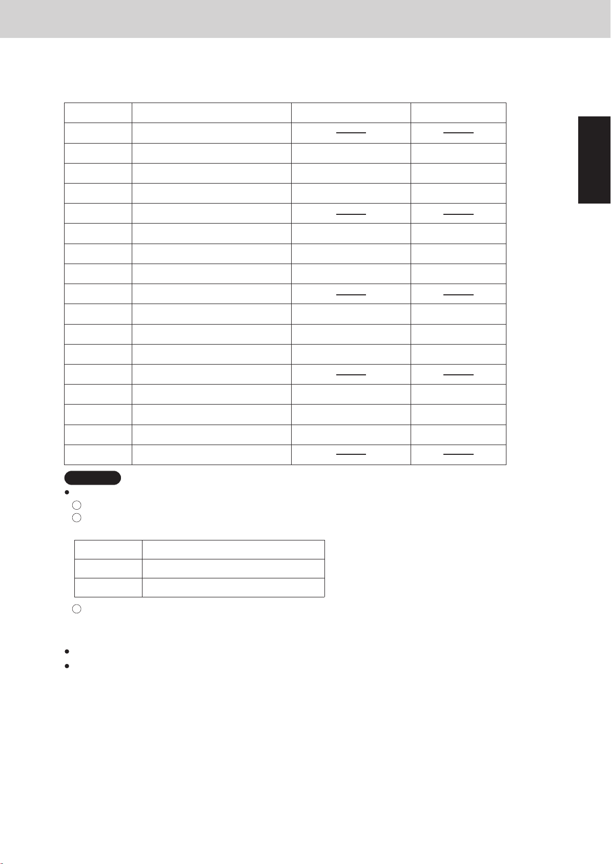
The system entirely becomes to the silent mode by setting in the main outdoor unit.
EEPROM setting in main outdoor unit
CODE : 05
Setting No.
0
1
2
3
4
5
6
7
8
10
11
Mode
Invalidity (Factory preset mode)
Capacity is given priority
Capacity is given priority
Capacity is given priority
Never use
Capacity is given priority
Capacity is given priority
Capacity is given priority
Never use
Silent is given priority9
Silent is given priority
Silent is given priority
External input to PCB
Necessary
Necessary -5dB
Necessary
Unnecessary
Unnecessary -5dB
Unnecessary
Necessary
Necessary -5dB
Necessary
Silent effect
-3dB
1
-7dB
-3dB
-7dB
-3dB
-7dB
12
13
14
15
16
NOTE
When the setting is “external input necessary”, this function works in either of the following way
1
short circuiting "SILENT” plug on the PCB.
2
-1 Change setting the outdoor unit EEPROM CODE: 78 to "01".
CODE: 78
Setting No.
0
1
2
-2 When setting in Quiet operation by the indoor unit address 1 remote controller (CZ-RTC5):
*Regarding the method of setting Quiet operation, see the Operating Instructions provided with the
remote controller.
When the setting is “external input to PCB unnecessary”, this function always works.
When the setting is “Capacity is given priority”, this function is interrupted in the following conditions.
Cooling operation: Ambient temperature ≥ 38°C
Heating operation: Ambient temperature < 2°C
Input by indoor unit remote controller
Never use
Silent is given priority
Silent is given priority
Silent is given priority
Never use
Invalid (Factory preset mode)
Valid
Unnecessary
Unnecessary -5dB
Unnecessary
-3dB
-7dB
1 - 13
Page 24
5. Outdoor Unit CCU (command controller
6. Outdoor Unit CCU (command controller unit) Control
2WAY VRF SYSTEM
Control Functions
2WAY VRF SYSTEM
Control Functions
6. Outdoor Unit CCU (command controller unit) Control
Operating
mode of
indoor unit
Operating
mode of
outdoor unit
Operating
mode of
compressor
Thermostat
ON/OFF
MOV pulse of indoor unit
Stop
Cooling
Stop
Operation
Stop
Operation
Stop
Operation
Stop
Stop
Stop
OFF
OFF
ON
ON
Operation
20
20
20
20
20
20
20
20
20
20
20
60 ~ 480 (SH control*
1
)
65 - 480 pulses (SC control*
3
)
20
Operation
Operation
Fan (only)
Cooling
Heating
Heating
Cooling
Cooling
Heating
Heating
1-2. Indoor unit with RAP valve kit
Go to previous page and see the comments with asterisks *1 and *3.
In the case of special controls, the MOV performs a special operation.
For details, see “3. Special Control” under this section.
unit : pulse
unit) Control
Mini VRF SYSTEM
Control Functions - Outdoor unit
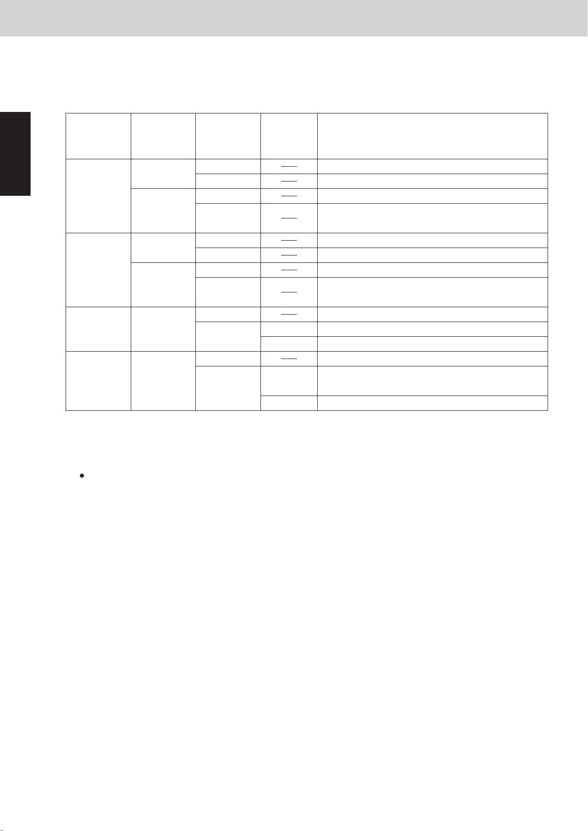
Some actuators of indoor unit are controlled by CCU.
(1)
MOV of Indoor Unit
1-1. Indoor unit without RAP valve kit
1
Operating
mode of
indoor unit
Stop
Fan (only)
Cooling
Heating
*1 SH control adjusts the difference between the liquid temperature and gas temperature in indoor unit.
SH = gas temperature (E3) - liquid temperature (E1)
Target SH is 3 degrees Celsius when the load level of indoor unit is “30” or “31 (test run)”.
Target SH will be increased up to 17.5 degrees Celsius when the load level of indoor unit is low.
When the refrigerant amount in the system is adjusted, it is necessary to select test run mode that the
required level becomes “31”.
*2 MOV pulse changes to 55 for 1 minute when the MOV pulse continues to be 55 or more for 10 minutes.
The purpose of this control is to decrease the flow volume of the refrigerant so that room temperature can
be detected with less influence of heat from the refrigerant.
*3 SC control adjusts the difference in temperature between the liquid temperature in indoor unit and
high-pressure saturated temperature in outdoor unit.
SC = high-pressure sensor temperature (HPS) - liquid temperature (E1)
Target SC is 5 - 15 degrees Celsius according to the operating condition.
Operating
mode of
outdoor unit
Cooling
Heating
Cooling
Heating
Cooling
Heating
Operating
mode of
compressor
Stop
Operation
Stop
Operation
Stop
Operation
Stop
Operation
Stop
Operation
Stop
Operation
Thermostat
ON/OFF
OFF
ON
OFF
ON
20
20
85
65 ~ 80
(prevent remaining refrigerant )
20
20
85
65 ~ 80
(prevent remaining refrigerant)
20
20
60 ~ 480 (SH control*
85
55 ~ 80 (prevent remaining refrigerant,
suction temperature control*
65 - 480 pulses (SC control*
MOV pulse of indoor unit
1
)
2
)
3
)
unit : pulse
1 - 14
Page 25

5. Outdoor Unit CCU (command controller
2WAY VRF SYSTEM
Control Functions
6. Outdoor Unit CCU (command controller unit) Control
unit) Control
Mini VRF SYSTEM
Control Functions - Outdoor unit
1-2. Indoor unit with RAP valve kit
Operating
mode of
indoor unit
Stop
Fan (only)
Cooling
Heating
Go to previous page and see the comments with asterisks *1 and *3.
In the case of special controls, the MOV performs a special operation.
For details, see “3. Special Control” under this section.
Operating
mode of
outdoor unit
Cooling
Heating
Cooling
Heating
Cooling
Heating
Operating
mode of
compressor
Stop
Operation
Stop
Operation
Stop
Operation
Stop
Operation
Stop
Operation
Stop
Operation
Thermostat
ON/OFF
OFF
ON
OFF
ON
20
20
20
20
20
20
20
20
20
20
60 ~ 480 (SH control*
20
20
65 - 480 pulses (SC control*
MOV pulse of indoor unit
1
)
3
)
unit : pulse
1
1 - 15
Page 26
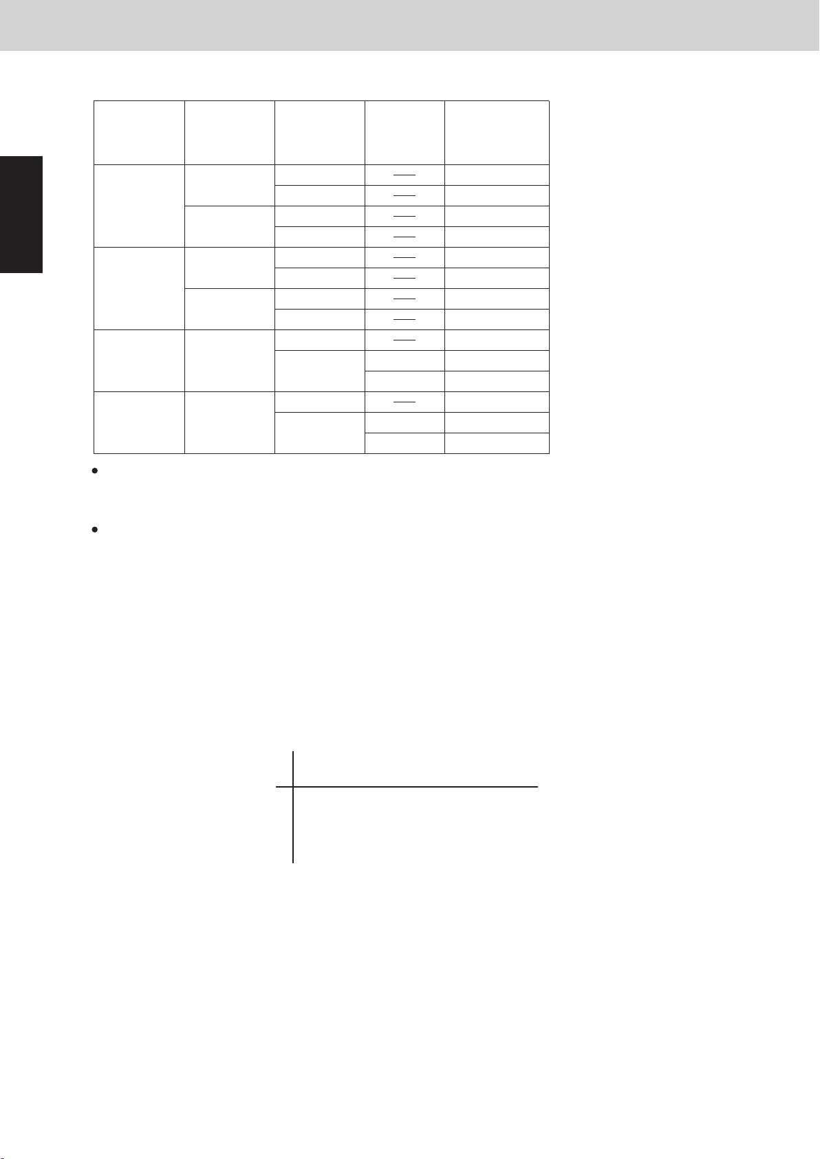
5. Outdoor Unit CCU (command controller
6. Outdoor Unit CCU (command controller unit) Control
2WAY VRF SYSTEM
Control Functions
2WAY VRF SYSTEM
Control Functions
6. Outdoor Unit CCU (command controller unit) Control
3-2. Heating mode
The indoor unit fan in heating mode is stopped from the CCU in the following condition.
Discharge air temperature of indoor unit ≤ 20°C
High pressure saturated temperature (HPT) in outdoor unit≤ 25°C
Liquid temperature (E1) in indoor unit ≤ 20°C
EEPROM setting in main outdoor unit
CODE: 0C
Indoor unit
operation mode
Setting No.
0
1
2
4
6
7 (Factory
preset mode)
3
5
Movement of drain pump
Invalid
DP operates for 20 minutes and stops for 2 hours
DP operates for 20 minutes and stops for 20 minutes
DP always operates
DP operates for XX minutes when indoor unit's operation changes;
from thermostat ON or thermostat OFF → operation stopped.
DP operates for XX minutes when indoor unit's operation changes;
from thermostat ON → thermostat OFF or operation stopped.
All mode
Cooling mode
Dry mode
Heating mode
Cooling mode
Dry mode
Both Setting No. 4 and 5 functions.
DP operates for XX minutes when indoor unit's operation changes
from thermostat ON or thermostat OFF → operation stopped.
(4) Drain Pump Control
The CCU intervenes in drain pump control of the indoor
unit according to the setting in EEPROM in the outdoor unit.
The drain pump operates from the CCU control at the following condition.
DP counter ≥ 5
*The DP counter counts each oil recovery control, and 4-way Valve Adjustment Control in cooling operation.
Liquid temperature (E1) in the indoor unit which selected cooling mode < 0 °C
* Regardless of operating / stopped mode
*
To activate this function, it is necessary to set EEPROM on the main outdoor unit PCB.
*
When any of setting Nos. 4 – 7 is selected, this function works only for the type of F2, M1, E2.
Low Silhouette Ducted type indoor unit
In Low Silhouette Ducted types, dirt might be accumulated when water collects in the drain pan for a long
term.
Therefore, the drain pump works longer to drain water surely.
unit) Control
Mini VRF SYSTEM
Control Functions - Outdoor unit
(2) RAP Valve Kit
1
(3) Indoor Fan Speed Control
Operating
mode of
indoor unit
Stop
Fan (only)
Cooling
Heating
RAP valve kit state (ON/OFF) is displayed on "D" in DSBE column when the Checker software is used.
0:OFF
1:ON
In the case of special controls, the MOV performs a special operation.
For details, see “3. Special Control” under this section.
The CCU intervenes in fan control of the indoor unit according to the status of the operating mode.
The priority order of fan control by the CCU is higher than that of indoor units.
Operating
mode of
outdoor unit
Cooling
Heating
Cooling
Heating
Cooling
Heating
Operating
mode of
Compressor
Stop
Operation
Stop
Operation
Stop
Operation
Stop
Operation
Stop
Operation
Stop
Operation
Thermostat
ON/OFF
OFF
ON
OFF
ON
RAP valve kit
ON/OFF
OFF
OFF
OFF
OFF
OFF
OFF
OFF
OFF
OFF
OFF
OFF
OFF
OFF
ON
3-1. Dry mode
Indoor unit fan operated in the dry mode is controlled from the CCU as shown in the figure below.
+ 1.0 degrees Celsius
* DTi = ( Air intake temperature of indoor unit) - (Preset temperature by remote controller)
DTi
Preset fan speed by remote controller
Fan speed
In the case of thermostat ON : “L”
In the case of thermostat OFF : “LL”
1 - 16
Page 27
5. Outdoor Unit CCU (command controller
2WAY VRF SYSTEM
Control Functions
6. Outdoor Unit CCU (command controller unit) Control
unit) Control
Mini VRF SYSTEM
Control Functions - Outdoor unit
3-2. Heating mode
The indoor unit fan in heating mode is stopped from the CCU in the following condition.
(4) Drain Pump Control
Discharge air temperature of indoor unit ≤ 20°C
High pressure saturated temperature (HPT) in outdoor unit≤ 25°C
Liquid temperature (E1) in indoor unit ≤ 20°C
The CCU intervenes in drain pump control of the indoor
unit according to the setting in EEPROM in the outdoor unit.
The drain pump operates from the CCU control at the following condition.
DP counter ≥ 5
*The DP counter counts each oil recovery control, and 4-way Valve Adjustment Control in cooling operation.
Liquid temperature (E1) in the indoor unit which selected cooling mode < 0 °C
* Regardless of operating / stopped mode
Low Silhouette Ducted type indoor unit
In Low Silhouette Ducted types, dirt might be accumulated when water collects in the drain pan for a long
term.
Therefore, the drain pump works longer to drain water surely.
*
To activate this function, it is necessary to set EEPROM on the main outdoor unit PCB.
EEPROM setting in main outdoor unit
CODE: 0C
Setting No.
0
Invalid
Movement of drain pump
Indoor unit
operation mode
1
1
2
3
4
5
6
7 (Factory
preset mode)
*
When any of setting Nos. 4 – 7 is selected, this function works only for the type of F2, M1, E2.
DP operates for 20 minutes and stops for 2 hours
DP operates for 20 minutes and stops for 20 minutes
DP always operates
DP operates for XX minutes when indoor unit's operation changes;
from thermostat ON → thermostat OFF or operation stopped.
DP operates for XX minutes when indoor unit's operation changes;
from thermostat ON or thermostat OFF → operation stopped.
Both Setting No. 4 and 5 functions.
DP operates for XX minutes when indoor unit's operation changes
from thermostat ON or thermostat OFF → operation stopped.
All mode
Cooling mode
Dry mode
Heating mode
Cooling mode
Dry mode
1 - 17
Page 28
5. Outdoor Unit CCU (command controller
6. Outdoor Unit CCU (command controller unit) Control
2WAY VRF SYSTEM
Control Functions
2WAY VRF SYSTEM
Control Functions
7. Oil Control
(1) Oil Level
(2) Oil Level Detection
Conditions of oil level in compressor JudgmentOil level
2
1
0
State
Sufficient
Possibility of
shortage
Shortage
The compressor contains sufficient oil. There is no problem.
There will be a risk of oil shortage soon.
Confirm that oil is improved after performing
the oil recovery control operation.
The compressor oil is short against
required level for normal operation.
Confirm that oil level is improved after
performing the oil recovery control among
systems.
At the time immediately after the oil level changes from 2 to 1, there is a specified amount of oil in the compressor.
Namely, soon after the oil level is changed from 1 to 2, the oil in the compressor is sufficient.
After about 1-hour operation, if the oil level “0” indication continues for more than 5 to 10 minutes, it seems to come
short of oil in the system. Check valves related to oil recovery operation, the refrigerant tubing and for any oil leakage.
The compressor oil in the crankcase is sent by bypass via a capillary tube to the low-pressure circuit.
The temperature detected by an oil sensor is used to determine whether it is oil (warm) or refrigerant (cold).
(3) Self-separator Oil Recovery Control
When a low oil level (1 or 0) is detected, oil is recovered from the oil separator to the compressor through the ORVR.
(4)
4-1.
System Oil Recovery Control
The system oil recovery control is performed by operating all the systems.
Start of system oil recovery control
When the oil level of compressors is “0”, the system oil recovery control will start.
When the accumulated time reaches 60 minutes under the condition of oil level “1” or lower, the system oil
recovery control will start.
This timer will be cleared when the oil level “2” continues for 5 minutes.
unit) Control
*
Operating time “XX” under the section “(4) Drain Pump Control” described on previous page is able to set
1
in EEPROM of the main outdoor unit.
EEPROM setting in main outdoor unit
CODE: 2B
Setting No.
20
*
*
In the above 2 cases, the drain pump operates by the signal of indoor PCB, not by the CCU.
30
40
50 50 (minutes)
60
The drain pump always operates when the indoor unit is thermostat ON in cooling operation.
Once the drain pump operates, it keeps operating for 20 minutes.
(factory preset mode)
XX
20 (minutes)
30 (minutes)
40 (minutes)
60 (minutes)
Control Functions - Outdoor unit
Mini VRF SYSTEM
(5) Discharge Air Temperature Control
For Type F2, M1 and E2 indoor units, discharge air temperature is controlled from the CCU to prevent
dew condensation on duct surface in cooling operation.
The CCU monitors and adjusts ∆To of indoor unit.
The adjustment is made by compressor capacity and MOV operation in the indoor unit.
∆To : Cooling (Discharge air temperature) - (Preset discharge air temperature)
Situation in which indoor unit thermostat OFF by discharge air temperature control
*
EEPROM setting in main outdoor unit
CODE: E1
Heating (Preset discharge air temperature) - (Discharge air temperature)
∆To ≤ - 3.5 degrees Celsius, and this condition continues for 7 minutes
∆To < - 2.0 degrees Celsius, and this condition continues for (20 + XX) minutes
The above mentioned “XX” is able to set in EEPROM of the main outdoor unit.
Setting No.
-20
-19
-18
...
XX
-20 (minutes)
-19 (minutes)
-18 (minutes)
...
0
...
10
*
Regarding the preset discharge air temperature that is set in the indoor unit is able to change,
see the section “5. REMOTE CONTROLLER FUNCTIONS” in this Service Manual.
0 (minutes)
(factory preset mode)
...
10 (minutes)
1 - 18
Page 29
6. Oil Control
2WAY VRF SYSTEM
Control Functions
7. Oil Control
Mini VRF SYSTEM
Control Functions - Outdoor unit
(1) Oil Level
2
1
0
At the time immediately after the oil level changes from 2 to 1, there is a specified amount of oil in the compressor.
Namely, soon after the oil level is changed from 1 to 2, the oil in the compressor is sufficient.
After about 1-hour operation, if the oil level “0” indication continues for more than 5 to 10 minutes, it seems to come
short of oil in the system. Check valves related to oil recovery operation, the refrigerant tubing and for any oil leakage.
(2) Oil Level Detection
The compressor oil in the crankcase is sent by bypass via a capillary tube to the low-pressure circuit.
The temperature detected by an oil sensor is used to determine whether it is oil (warm) or refrigerant (cold).
(3) Self-separator Oil Recovery Control
When a low oil level (1 or 0) is detected, oil is recovered from the oil separator to the compressor through the ORVR.
State
Sufficient
Possibility of
shortage
Shortage
Conditions of oil level in compressor JudgmentOil level
The compressor contains sufficient oil. There is no problem.
There will be a risk of oil shortage soon.
The compressor oil is short against
required level for normal operation.
Confirm that oil is improved after performing
the oil recovery control operation.
Confirm that oil level is improved after
performing the oil recovery control among
systems.
1
(4)
System Oil Recovery Control
The system oil recovery control is performed by operating all the systems.
4-1.
Start of system oil recovery control
When the oil level of compressors is “0”, the system oil recovery control will start.
When the accumulated time reaches 60 minutes under the condition of oil level “1” or lower, the system oil
recovery control will start.
This timer will be cleared when the oil level “2” continues for 5 minutes.
1 - 19
Page 30
6. Oil Control
2WAY VRF SYSTEM
Control Functions
7. Oil Control
8. 4-Way Valve Adjustment Control
2WAY VRF SYSTEM
Control Functions
The first operation after turning on power supply to outdoor unit.
The mode of the system changes.
The purpose of this control is to change over the 4-way valve appropriately with big pressure difference.
This control is performed at the following conditions.
Cooling operation
*When the above operation is finished, normal operation starts at the horsepower determined by the indoor units
where thermostats are ON.
*When the above operation is finished, normal operation starts at the horsepower determined by the indoor units
where thermostats are ON.
The first operation after all outdoor units stopped for 60 minutes.
For 60 seconds
Indoor units
Control time
Outdoor units
MOV
RAP valve kit
Fan
All outdoor units operate at the maximum capacity.
MOV at all indoor units operate at a fixed pulse according to the indoor unit
capacity.
All indoor units operate in Cooling mode (OFF status).
Fan rotates at the set fan speed depending on the indoor unit operation mode
or at fan speed “LL”.
Minimum 1 min - Maximum 20 min [until max. (pressure sensor temp.) 35°C]
Indoor units
Control time
Outdoor units
MOV
RAP valve kit
Fan
All outdoor units operate at the maximum capacity.
MOV at all indoor units initially operates 250 pulses and then runs in SC control mode.
All indoor units operate in heating mode (ON status).
Fan rotates at the set fan speed depending on the indoor unit operation mode or at
“LL” fan speed, or stops.
Heating operation
4-2.
Simplified flow of system oil recovery control
The system oil recovery control shall be performed as the flow mentioned below.
Normal operation → System oil recovery control → Normal operation
In the case of cooling mode
1
Indoor units
In the case of heating mode
Indoor units
Control time
Outdoor units
Outdoor units
RAP valve kit
Control time
RAP valve kit
MOV
Fan
MOV
For max 5 minutes
All outdoor units operate at maximum horsepower.
MOV at all indoor units operate at a fixed pulse according to the indoor unit
capacity.
All indoor units operate in Cooling mode (OFF status).
Fan rotates at the set fan speed depending on the indoor unit operation mode
or at fan speed “LL”.
For 2 minutes
All outdoor units operate at more than half horsepower.
MOV at all indoor units operate at 250 pulses.
All indoor units operate in Heating mode (ON status.)
Control Functions - Outdoor unit
Mini VRF SYSTEM
(5) Indoor Unit Self Oil Recovery Control
This control is carried out regularly when the system is in cooling mode.
During stopped, fan mode setting or thermostat OFF condition at the indoor unit, MOV of the indoor unit is opened
regularly for 1 minute (at the interval of approximately 40 minutes).
During the thermostat ON, MOV of the indoor unit is opened 20 pulses from the current status.
Type of
indoor unit
D1, K1, K2
Except
D1, K1, K2
of indoor unit
For
Fan
Operating
mode
Stop
Fan
Cooling
Stop
Fan
Cooling
Fan rotates at the set fan speed depending on the indoor unit operation mode
or at fan speed “LL”.
EEPROM setting in main outdoor unit
CODE: 24
Thermostat
ON/OFF
OFF
ON
OFF
ON
Pulse of MOV
80 – 160
80 - 160
80 – 160
Present pulse+20
80 – 160
80 – 160
80 – 160
Present pulse+20
Setting No. 0
Fan speed
Stop
LL
Set speed
L
Stop
Stop
Set speed
L
Flap
Setting No. 1
Fan speed
LL
LL
Set speed
L
Stop
Stop
Set speed
L
Open
Open
Flap
* MOV pulse might be different from the table listed above depending on the use conditions.
1 - 20
Page 31
7. 4-Way Valve Adjustment Control
8. 4-Way Valve Adjustment Control
2WAY VRF SYSTEM
Control Functions
Mini VRF SYSTEM
Control Functions - Outdoor unit
The purpose of this control is to change over the 4-way valve appropriately with big pressure difference.
This control is performed at the following conditions.
The first operation after turning on power supply to outdoor unit.
The first operation after all outdoor units stopped for 60 minutes.
The mode of the system changes.
Cooling operation
Control time
Outdoor units
MOV
Indoor units
*When the above operation is finished, normal operation starts at the horsepower determined by the indoor units
where thermostats are ON.
Heating operation
Control time
Outdoor units
RAP valve kit
Fan
Minimum 1 min - Maximum 20 min [until max. (pressure sensor temp.) 35°C]
All outdoor units operate at the maximum capacity.
For 60 seconds
All outdoor units operate at the maximum capacity.
MOV at all indoor units operate at a fixed pulse according to the indoor unit
capacity.
All indoor units operate in Cooling mode (OFF status).
Fan rotates at the set fan speed depending on the indoor unit operation mode
or at fan speed “LL”.
1
MOV
RAP valve kit
Indoor units
Fan
*When the above operation is finished, normal operation starts at the horsepower determined by the indoor units
where thermostats are ON.
MOV at all indoor units initially operates 250 pulses and then runs in SC control mode.
All indoor units operate in heating mode (ON status).
Fan rotates at the set fan speed depending on the indoor unit operation mode or at
“LL” fan speed, or stops.
1 - 21
Page 32

8. Defrost Control
2WAY VRF SYSTEM
Control Functions
9. Defrost Control
2WAY VRF SYSTEM
Control Functions
(4)
When the heating operation time at system has exceeded “XX” minutes (35 minutes at initial setting), and at
least one unit satisfies the decision of defrosting, the defrosting operation is effective.
9. Defrost Control
Heating Operation Set Time (Defrosting Operation Prohibiting Time)
(5)
Defrost ends when either of the below defrost end judgment conditions is met.
Defrost End Judgment Conditions
(6)
If there is only 1 outdoor unit in the refrigerant system, a reverse cycle defrost will be carried out.
It is possible to change the stopped time according to the setting.
For the maximum defrost time, see the table shown above.
Reverse Cycle Defrost
* XX is able to set in EEPROM of main outdoor unit.
* Defrost control is also performed at outdoor units where the outdoor unit heat exchanger is not functioning as
an evaporator (such as stopped outdoor units).
EEPROM setting in main outdoor unit
CODE: A3
Setting No.
0
1
...
XX
0 (minutes)
35 (minutes)
(factory preset code)
1 (minutes)
...
35
...
60
...
60 (minutes)
Condition 1: The temperatures are 15°C or higher at all heat exchanger sensors installed on the outdoor
unit.
One minute has elapsed under the condition that the temperatures are 10°C or higher at all heat
exchanger sensors installed in the outdoor unit.
Condition 3:
Condition 2:
13 minutes have elapsed.
Defrost flow E:C:Evaporator operation
Condenser operation
E → C:
C → E:
Switching evaporator operation to condenser operation
Switching condenser operation to evaporator operation
Indoor unit
Cooling mode
Heating mode
Defrost
preparation
Defrost in
progress
Defrost
end
judgment
Defrost end
Thermostat ON EC→E E → C
Thermostat OFF EC→E
E → C
Thermostat ON EC→E E → C
Fan (only) EC→E
E → C
Thermostat OFFEC→E
E → C
Compressor OperatingStopped Stopped
4-way valve OFFON→OFF OFF→ON
Stopped EC→E
E → C
Outdoor unit status C
E → CC → E
TimeMaximum 13 minutes1 minute 1 minute
Mini VRF SYSTEM
Control Functions - Outdoor unit
(1) Type of Defrost Control
This system uses the reverse cycle defrost.
(2) Forced Conditions
Defrost does not begin again for 35 minutes of operation after defrost was once completed.
If the outdoor unit is stopped while defrosting due to protection control or another reason, then defrost control will
not start for a minimum of 10 minutes after restart occurs.
1
Even if all indoor units are stopped while defrosting, defrost control continues until it ends.
(3) Frost Detection
Frost detection does not occur for 5 minutes after operation starts.
Frost is detected when minimum heat exchanger temperature meets any one of the condition 1 - 3 below.
Condition 1: Minimum heat exchanger temperature drops below L2 line shown in the figure below and detects
Condition 2:
Condition 3: Minimum heat exchanger temperature drops below -3°C and detects for a total of 90 minutes
twice for 4 minutes without interruption while the compressor is operating.
Minimum heat exchanger temperature drops below L1 line shown in the figure below and detects
for a total of 60 minutes while the compressor is operating.
while the compressor is operating.
Minimum heat exchanger temperature °C
15 (Defrosting operation-end temperature)
unit: °C
-25
-1
-3
-8
-10
Frost detection area below the bold lines L1 and L2
-25.5
-27.5
10
L1
L2
Ambient temperature°C
1 - 22
Page 33
Mini VRF SYSTEM
2WAY VRF SYSTEM
Control Functions
9. Defrost Control
CC
8. Defrost Control
(4)
Heating Operation Set Time (Defrosting Operation Prohibiting Time)
When the heating operation time at system has exceeded “XX” minutes (35 minutes at initial setting), and at
least one unit satisfies the decision of defrosting, the defrosting operation is effective.
* XX is able to set in EEPROM of main outdoor unit.
EEPROM setting in main outdoor unit
CODE: A3
Setting No.
XX
Control Functions - Outdoor unit
1
0
1
...
35
...
60
0 (minutes)
1 (minutes)
...
35 (minutes)
(factory preset code)
...
60 (minutes)
* Defrost control is also performed at outdoor units where the outdoor unit heat exchanger is not functioning as
an evaporator (such as stopped outdoor units).
(5)
Defrost End Judgment Conditions
Defrost ends when either of the below defrost end judgment conditions is met.
Condition 1: The temperatures are 15°C or higher at all heat exchanger sensors installed on the outdoor
unit.
Condition 2:
One minute has elapsed under the condition that the temperatures are 10°C or higher at all heat
exchanger sensors installed in the outdoor unit.
Condition 3:
(6)
Reverse Cycle Defrost
13 minutes have elapsed.
If there is only 1 outdoor unit in the refrigerant system, a reverse cycle defrost will be carried out.
Defrost flow E:C:Evaporator operation
Condenser operation
Indoor unit
E → C:
C → E:
Outdoor unit status C
Compressor OperatingStopped Stopped
4-way valve OFFON→OFF OFF→ON
Cooling mode
Heating mode
Switching evaporator operation to condenser operation
Switching condenser operation to evaporator operation
Defrost
preparation
E →
Stopped EC→E
Fan (only) EC→E
Thermostat ON EC→E E → C
Thermostat OFFEC→E
Thermostat ON EC→E E → C
Thermostat OFF EC→E
TimeMaximum 13 minutes1 minute 1 minute
Defrost in
progress
judgment
Defrost
end
Defrost end
→ E
E → C
E → C
E → C
E → C
It is possible to change the stopped time according to the setting.
For the maximum defrost time, see the table shown above.
1 - 23
Page 34
9. Demand Control
2WAY VRF SYSTEM
Control Functions
10. Demand Control
2WAY SYSTEM
Control Functions-Outdoor Unit
10. Upper Current Limitation Mode
EEPROM setting in main outdoor unit
EEPROM setting in main outdoor unit
CODE: 1A
CODE: 1E
Setting No.
0 No display
1
2
Information is displayed when input of demand control is set (factory preset mode).
Information is displayed only when the capacity is restricted by demand control.
Control
Contact 1
Upper current limitation setting
Contact 2
No control (Operates to maximum capacity)
Operates to XX% of the upper limit for the rated current.
Operates to YY% of the upper limit for the rated current.
Forced thermostat OFF setting
Serial-parallel I/O must be connected in order to perform demand control.
The below input is received by serial-parallel I/O, and demand control is performed.
The demand values can be set as needed with serial-parallel I/O.
It is able to display the present condition on the remote controller.
* The rated current indicates the current value that is listed in the catalog or similar material.
* XX and YY are able to set in EEPROM of main outdoor unit.
: Input present : Input not present
(3) Serial-parallel I/O
CODE: 1B
Setting No.
0
40
45
-1
130
YY
0
40
45
No control
130
Setting No.
0
40
45
-1
130
100
XX
0
No control
130
Interval of “5”
40
45
100 (factory preset mode)
70
Interval of “5”
70 (factory preset mode)
NOTE
Since the pattern “A” and “B” perform the outdoor unit current demand control (compressor’s suppressive
drive), it is easy to grasp energy saving amount.
However, it may cause the reduction of capacity in all indoor units of the same refrigerant system.
In order to make the indoor unit (group) only valid as the energy saving function where the Energy Saving
button is pressed and not to influence to other indoor units, be sure to set the outdoor unit EEPROM setting
DN18 to “1” and DN19 to “0”.
Mini VRF SYSTEM
Control Functions - Outdoor unit
(1)
Usual Demand Control
Demand control is performed to suppress the horsepower not to make the primary current exceed the setting
value.
The standard value of the limit current is shown in the table below.
Type of outdoor unit 10HP unit:Amp.
Cooling mode
1
(2)
Heating mode
The system current value is controlled at rated current value without demand input as shown in the table below.
Energy Saving Button (CZ-RTC5)
When the Energy Saving button of the indoor unit remote controller is pressed, demand control is performed
according to EEPROM : 1A values.
Setting of Energy Saving button: Outdoor unit EEPROM Setting item DN18, DN19
Energy saving operation when the Energy Saving button is pressed provides 3 patterns of control.
Patterns:
A.
B.
C.
Outdoor unit EEPROM setting (DN18) :
The marking “” indicated in the following table is applicable to the function of control.
Type of outdoor unit 10HP
Limited ratio against standard value
Limit value
Demand control is performed under the current limitation values set at the outdoor unit EEPROM setting (DN1A).
In addition, the indoor unit controls the limitation of discharge temperature.
Demand control is performed under the current limitation values set at the outdoor unit EEPROM setting (DN1A).
Discharge temperature limitation control is performed set at the indoor unit EEPROM setting.
Setting No.
(Factory preset mode)
Cooling mode
Heating mode
0
1
2 Pattern “B” only demand control
3
8HP
9.6
10.2
HP=Horsepower
Discharge
temperature
control
14.7
11.6
8HP
130%
12.4
13.2
HP=Horsepower
130%
19.2
15.0
Demand
control
unit:Amp.
No controls
Pattern “C” only discharge temperature
Pattern “A” demand control + discharge temp. control
Remarks
Outdoor unit EEPROM setting (DN19):
Setting of control validity range when pressing the Energy Saving button
Setting No.
(Factory preset mode)
*When the pattern “A” and “B” are selected, energy saving control becomes valid in the same range as the
setting “1” although the Setting No. is set to “0”.
0
1
Energy saving activates where Energy Saving button is pressed as a unit of indoor
unit (group).
Energy saving activates where Energy Saving button is pressed as a unit of indoor
unit including all refrigerant system.
1 - 24
Control range
Page 35
Mini VRF SYSTEM
2WAY SYSTEM
Control Functions-Outdoor Unit
10. Upper Current Limitation Mode
9. Demand Control
Control Functions - Outdoor unit
NOTE
Since the pattern “A” and “B” perform the outdoor unit current demand control (compressor’s suppressive
drive), it is easy to grasp energy saving amount.
However, it may cause the reduction of capacity in all indoor units of the same refrigerant system.
In order to make the indoor unit (group) only valid as the energy saving function where the Energy Saving
button is pressed and not to influence to other indoor units, be sure to set the outdoor unit EEPROM setting
DN18 to “1” and DN19 to “0”.
(3) Serial-parallel I/O
Serial-parallel I/O must be connected in order to perform demand control.
The below input is received by serial-parallel I/O, and demand control is performed.
The demand values can be set as needed with serial-parallel I/O.
1
Upper current limitation setting
Contact 1
: Input present : Input not present
* The rated current indicates the current value that is listed in the catalog or similar material.
* XX and YY are able to set in EEPROM of main outdoor unit.
EEPROM setting in main outdoor unit
CODE: 1A
Setting No.
0
40
45
100
Contact 2
No control (Operates to maximum capacity)
Operates to XX% of the upper limit for the rated current.
Operates to YY% of the upper limit for the rated current.
Forced thermostat OFF setting
XX
0
40
45
Interval of “5”
100 (factory preset mode)
Control
CODE: 1B
Setting No.
40
45
70
0
Interval of “5”
70 (factory preset mode)
YY
0
40
45
130
-1
It is able to display the present condition on the remote controller.
EEPROM setting in main outdoor unit
CODE: 1E
Setting No.
0 No display
1
2
Information is displayed when input of demand control is set (factory preset mode).
Information is displayed only when the capacity is restricted by demand control.
130
No control
1 - 25
130
-1
130
No control
Page 36
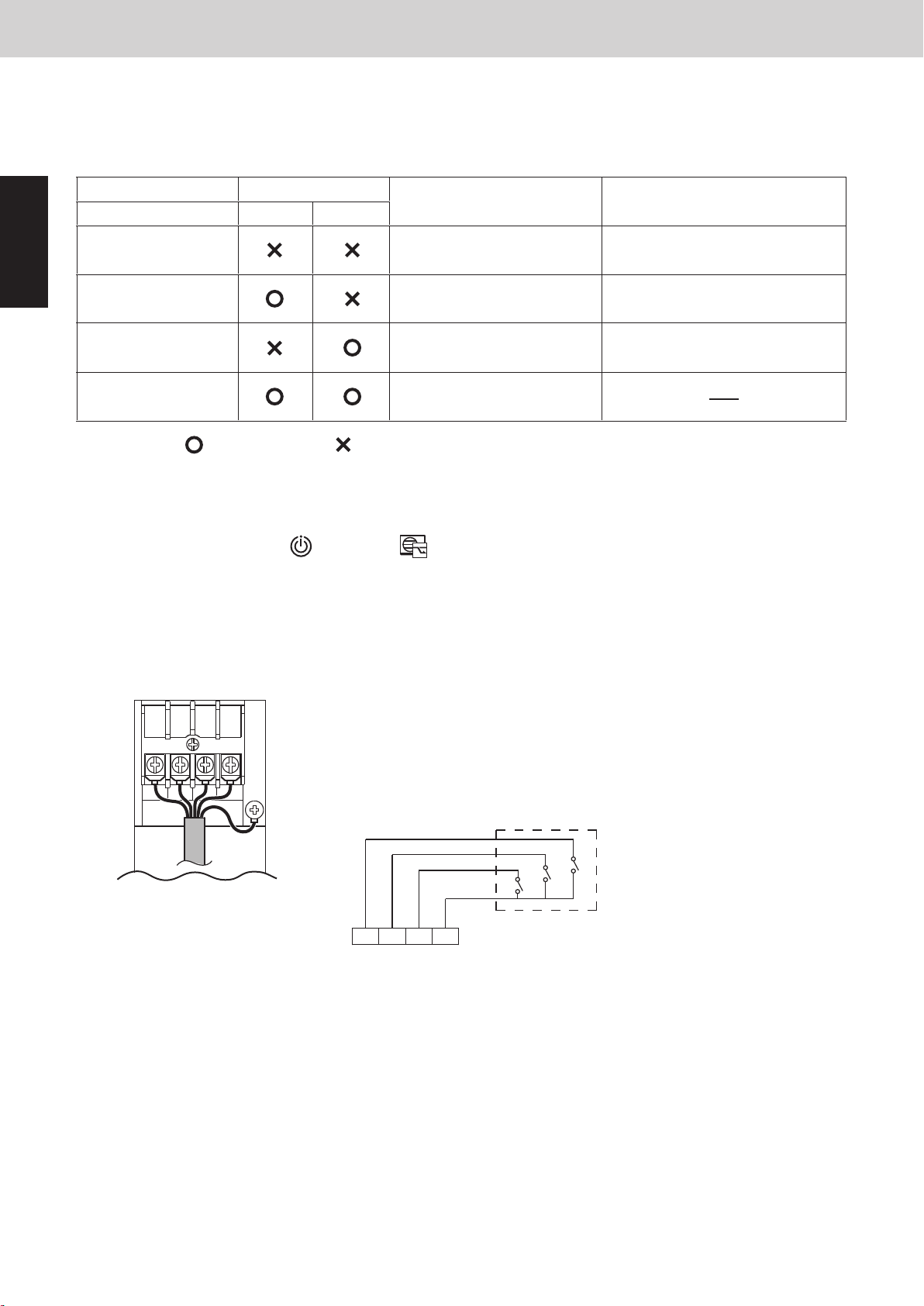
2WAY SYSTEM
Control Functions
10. Demand Control
2WAY SYSTEM
Control Functions-Outdoor Unit
10. Upper Current Limitation Mode
2WAY VRF SYSTEM
Control Functions
Case 1
→
The heating indoor units will be forced to thermostat OFF.
Number of thermostat ON indoor units in heating mode
Number of thermostat ON indoor units in heating mode
Number of thermostat ON indoor units in cooling mode >
Case 2
→
system selects cooling mode
system selects heating mode
The cooling indoor units will be forced to thermostat OFF.
Number of thermostat ON indoor units in cooling mode <
While the system is operating, the system judges whether to switch the mode in XX minutes intervals.
While the system is stopped, change the mode immediately.
12. Other Functions
EEPROM setting in main outdoor unit
CODE: 27
Setting No.
0
XX
Invalid
(factory preset mode)
30
40
30
40
50 50
60 60
90 90
120 120
180 180
240 240
*“XX” is able to be set in EEPROM on the outdoor unit’s PCB.
(It is impossible to perform the simultaneous cooling/heating operation.)
It is possible to select auto cooling/heating mode in each remote controller even in 2WAY VRF system.
The system changes to cooling or heating operation according to number of thermostat ON mode.
The system selects the mode that has more number of units with thermostat ON.
(1) Auto Cooling/Heating Function
9. Demand Control
Mini VRF SYSTEM
Control Functions - Outdoor unit
(4) When Using Demand Terminal Block
Demand terminal block must be connected in order to perform the demand control.
(It is also possible to connect the optional Seri-Para I/O unit (optional CZ-CAPDC2) and setup the system.)
The current limitation values can be set by changing either contact.
COM short circuit
1
* The rated current indicates the current value that is listed in the catalog or service manual.
**In respect of connection method for demand terminal block and Seri-Para I/O unit, refer to the installation
instructions supplied with the unit.
During setting in LV1 - LV3, [CZ-RTC4]
controller of the indoor unit.
It is also possible to make setting that the display (symbol of demand-activated) is concealed as shown in the
following table.
* XX and YY are able to set in EEPROM of main outdoor unit.
Check " (3) Serial-parallel I/O " section.
Non
LV1
LV2
LV3
Seri-Para I/O unitDemand terminal block
Contact 1 Contact 2
No control
Operates to XX% of the upper
limit for the rated current
Operates to YY% of the upper
limit for the rated current
Forced thermostat OFF setting
: Input present : Input not present
Control
Operates to the maximum capacity.
Current is limited to the set values.
Current is limited to the set values.
[CZ-RTC5] (demand-activated) displays on the remote
Demand meaning
LV3 LV2 LV1 COM
Demand
Terminal block
LV3 LV2 LV1
DRED (Demand controller)
Relay contact point: No voltage relay
Current input is DC 24 V 10 mA
COM
Use a very small electric current contact point for the relay.
1 - 26
Page 37

10. Other Functions
2WAY VRF SYSTEM
Control Functions
12. Other Functions
Mini VRF SYSTEM
Control Functions - Outdoor unit
(1) Auto Cooling/Heating Function
It is possible to select auto cooling/heating mode in each remote controller even in 2WAY VRF system.
The system changes to cooling or heating operation according to number of thermostat ON mode.
The system selects the mode that has more number of units with thermostat ON.
(It is impossible to perform the simultaneous cooling/heating operation.)
While the system is operating, the system judges whether to switch the mode in XX minutes intervals.
While the system is stopped, change the mode immediately.
Case 1
Number of thermostat ON indoor units in cooling mode >
system selects cooling mode
→
The heating indoor units will be forced to thermostat OFF.
Case 2
Number of thermostat ON indoor units in cooling mode <
→
system selects heating mode
The cooling indoor units will be forced to thermostat OFF.
*“XX” is able to be set in EEPROM on the outdoor unit’s PCB.
EEPROM setting in main outdoor unit
CODE: 27
Number of thermostat ON indoor units in heating mode
Number of thermostat ON indoor units in heating mode
1
Setting No.
0
30
40
50 50
60 60
90 90
120 120
180 180
240 240
(factory preset mode)
XX
Invalid
30
40
1 - 27
Page 38
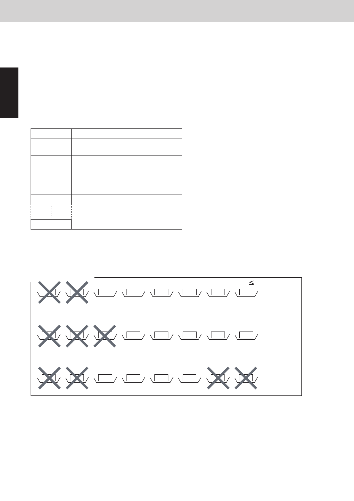
3WAY SYSTEM
Control Functions
13. Other Functions
10. Other Functions
(2) Maintenance Function for Power Supply Stop of Indoor Unit (E06 ignore)
The system can continue operation even if outdoor unit cannot communicate with some indoor units.
It is necessary to set to EEPROM the allowed number of operating indoor units not to be able to communicate.
The system will continue operating until the following condition is made to be satisfied.
Value set by the code “23” ≥No. of indoor units operated until the last moment because of communicative
disorder caused by power supply stop (excluding stopped indoor units).
However, the upper limit value set by the code "23" must be less than 25% of the total number of indoor units
1
of the system.
EEPROM setting in main outdoor unit
CODE: 23
Allowed number of missing indoor unitSetting No.
-1
0 0
1 1
This function is invalid
(factory preset mode)
22
Mini VRF SYSTEM
Control Functions - Outdoor unit
33
4
Never use
64
* However, the upper limit value set by the code "23" must be less than 25% of the total number of indoor
units of the system.
Examples :
In case of 8 indoor units, setting No. becomes “2”.
Normal operation
Operation continue: Indoor unit failure=2
ON ON ON ON ON OFF OFF OFF
Error occurs: Indoor unit failure=3 > Setting No “2”
ON ON ON ON ON OFF OFF OFF
Setting No “2”
Operation continue: Stopped units does not count
ON ON ON ON ON OFF OFF OFF
1 - 28
Page 39
11. Detailed Settings in EEPROM of Outdoor Unit
Control Functions - Outdoor unit
Mini VRF SYSTEM
Never use the DN code unlisted in the following table. (P) : Factory preset mode
DN Item Setting No.
0=Invalid (P) 1=Silent mode 1
05 Outdoor fan silent mode
0C Indoor unit drain pump forced operation
Measures against smell when indoor unit cooling
0D
thermostat OFF
Setting of control validity range when pressing the
19
Energy saving button
1A Demand 1 current (%)
1B Demand 2 current (%)
1E Demand remote controller display
23 E06 ignore function
24 Indoor Unit Self Oil Recovery Control
Auto Cooling / Heating Functions mode change mask
27
time
2A Dew condensation prevention control of indoor unit
2B DP operation time for slime measures
2=Silent mode 2,,,,, 15=Silent mode 15
(For details, see "4. Outdoor Unit Fan Control (6)")
0=Invalid
1=stop for 2 hours and drive for 20 minutes constantly
2=stop for 20 minutes and drive for 20 minutes constantly
3=Drive constantly
4-6=delay drive when thermostat OFF
7=delay drive when thermostat OFF (P)
(For details, see "5. Outdoor Unit CCU Control (4)")
0=Invalid (P)
1=Measures against smell
0=for group (P)
1=for refrigerant system
(For details, see “9. Demand Control (2)”)
0=0% 40=40%
45=45%,,,,, 100=100% (P) ,,,,,
130=130% -1=No control
(For details, see "9. Demand Control")
0=0% 40=40%
45=45%,,,,, 70=70% (P) ,,,,,
130=130% -1=No control
(For details, see "9. Demand Control")
0=No demand display
1=When demand ON, “demand - actived” display (P)
2=When forced thermostat OFF with demand ON,
“demand - actived” display
(For details, see "9. Demand Control")
-1=Invalid (P) 0=0
1=1 ,,,,, 3=3
4 - 64=Never use
(For details, see "10. Other Functions")
0=fan stop
1=fan operate & Te +5°C shift (For Type D1, K1, K2)
(For details, see "6. Oil Control (5)")
0=Invalid (P) 30=30 minutes
40=40 minutes ,,,,, 240=240 minutes
(For details, see "10. Other Functions (1)")
0=Invalid (P) 1=30 minutes
2=40 minutes 3=50 minutes
4=60 minutes
20=20 minutes 30=30 minutes (P)
40=40 minutes 50=50 minutes
60=60 minutes
(For details, see "5. Outdoor Unit CCU Control (4)")
1
1 - 29
Page 40
11. Detailed Settings in EEPROM of Outdoor
PCB and Functions
1. Outdoor Unit Control PCB
(1) Outdoor Unit Control PCB
LED2
LED1
SW2
SW1
CN-HPS
RUN
TEST
CN-EXG
STOP
CN-TO
CHK
CN-MOV2
CN-MOV1
CN-SILENT
CN-ROM
SA1
CN-OC
CN-EMG
CN-RC
CN-TERMINAL
CN-LPS
AP
MODE
A.ADD
DEF
CN-OIL
SW4
SW3
CN-SCT
CN-EXL
CN-DISCH
JP001
Unit
Mini VRF SYSTEM
Control Functions - Outdoor unit
Never use the DN code unlisted in the following table. (P) : Factory preset mode
DN Item Setting No.
1
Outdoor silent mode as input setting "Valid" or "Invalid"
78
from the indoor unit remote controller
Outdoor unit capacity
81
(Setting when the data is not stored in the EEPROM.
Do not change under normal conditions.)
A3 The minimum operating time 1 until defrosting
C1 O
E1
output change
2
Discharge air temperature control with thermostat OFF
additional time
0=Invalid (P)
1=Valid
(For details, see "4. Outdoor Unit Fan Control (6)")
0=Invalid 21=224 23=280
20=20 minutes 21=21 minutes ,,,,,
35=35 minutes (P) ,,,,, 40=40 minutes
41 - 90=Never use
(For details, see "8. Defrost Control (2)")
0=Continuously set OFF (P)
1=Refrigerant leak prevention (normal OFF)
2=Refrigerant leak prevention (normal ON)
3=Pumpdown control
(For details, see "3. Special Control (3)")
-20=-20 minutes -19=-19 minutes ,,,,,
0=0 minute (P) ,,,,, 10=10 minutes
(For details, see "5. Outdoor Unit CCU Control (5)")
1 - 30
Page 41

12. Outdoor Unit Control PCB
PCB and Functions
1. Outdoor Unit Control PCB
Mini VRF SYSTEM
Control Functions - Outdoor unit
(1) Outdoor Unit Control PCB
1
LED2
LED1
JP001
SW2
SW1
CN-DISCH
CN-EXL
CN-SCT
SW3
SW4
CN-OIL
DEF
A.ADD
CN-MOV2
CHK
CN-TO
STOP
CN-EXG
TEST
RUN
CN-HPS
CN-MOV1
CN-LPS
AP
MODE
CN-SILENT
SA1
CN-ROM
CN-TERMINAL
CN-EMG
CN-OC
CN-RC
1 - 31
Page 42
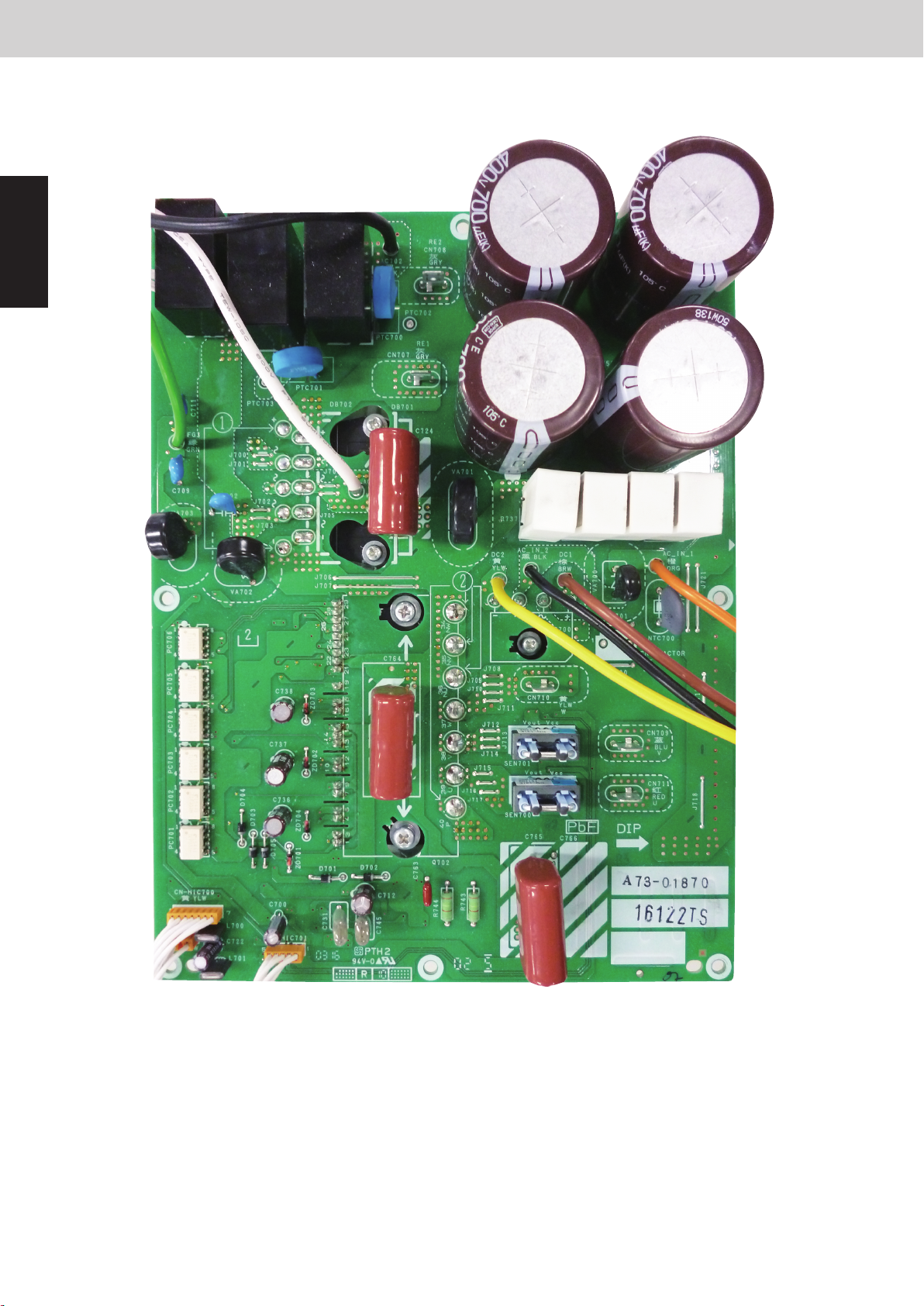
12. Outdoor Unit Control PCB
PCB and Functions
1. Outdoor Unit Control PCB
(2) Outdoor Unit HIC PCB
1
Mini VRF SYSTEM
Control Functions - Outdoor unit
1 - 32
Page 43

12. Outdoor Unit Control PCB
(3) Functions
A. ADD pin (2P, Black) Auto address setting pin
• Short-circuit this pin for 1 second or longer to automatically set the addresses at the indoor
units that are connected to that outdoor unit and are within the same system.
• The system address is "1" at the time of shipment. Auto address setting is necessary even for
communications lines in a single system where the inter-unit control wiring does not cross to
any other systems.
• While auto address setting is in progress, the 2 LEDs (LED1, 2: Red) on the outdoor unit
control PCB blink alternately. (Short-circuiting this pin while auto address setting is in progress
will stop the auto address setting operation.)
Mini VRF SYSTEM
Control Functions - Outdoor unit
1
SW1
DIP switch (2P, Black)
SW2
Rotary switch
(10 positions, Yellow)
SW3
DIP switch (2P, Black)
SW4
Rotary switch
(10 positions, Red)
Switches for setting system address 10s digit and 20s digit
• If 10 systems or more are set, the setting is made by a combination of this DIP switch and
S002.
• If 10 - 19 systems are set, set switch 1 (10s digit) to ON.
• If 20 - 29 systems are set, set switch 2 (20s digit) to ON, and set switch 1 (10s digit) to OFF.
• If 30 systems are set, set both switch 1 (10s digit) and switch 2 (20s digit) to ON.
(For details, see Table 1.)
Outdoor system address setting switch
• The setting is "1" at the time of shipment. It is not necessary to change the setting if wiring is
connected only to an outdoor unit and indoor units in a single system and the inter-unit control
wiring does not cross multiple systems.
• If wiring links the inter-unit control wiring for multiple systems to the same communications
lines, then a different address must be set for each refrigerant tubing system.
• If wiring links multiple systems, a maximum of 30 systems (up to 64 indoor units) can be
connected. This setting can be set up to "39," however control will be for 30 systems even
if the setting is set to higher than 30. An alarm will be displayed if system addresses are
duplicated. (For details, see Table 1.)
Switches for setting the 10s and 20s digit for the number of connected indoor units
• If 10 systems or more are set, the setting is made by a combination of this DIP switch and
SW4.
• If 10 - 15 units are set, set only switch 1 (10s digit) to ON.
• Switch 2 is not used. (For details, see Table 2.)
Switch for setting the number of connected indoor units.
In order to allow the outdoor unit to manage indoor units in the same refrigerant system, set the
number of connected indoor units. (For details, see Table 2.)
1 - 33
Page 44

12. Outdoor Unit Control PCB
Mini VRF SYSTEM
Control Functions - Outdoor unit
1
CN-TERMINAL pin
(3P, Black)
LED1, 2 (2P, Red) • LED 1 and 2 blink alternately while auto address setting is in progress.
RUN pin (2P, Black)
STOP pin (2P, Black) Stop pin
AP pin (2P, Black) Vacuuming pin
MODE pin (3P, Black) Indoor unit Heating/Cooling mode change pin
For communications circuit impedance matching
• A connecting socket (3P, Black) is attached to the terminal plug at the time of shipment from
the factory.
• In the case of link wiring which combines the inter-unit control wiring for multiple systems into
a single communications circuit, When using, refer to the item “4. Auto Address Setting” under
the section “7. TEST RUN”.
• Display the alarm contents for alarms which were detected by the outdoor unit.
Start pin
Short-circuit this pin and apply a pulse signal to start all indoor units in that refrigerant system.
Short-circuit this pin and apply a pulse signal to stop all indoor units in that refrigerant system.
• To perform vacuuming of the outdoor unit, short-circuit this pin and then turn the power ON.
All solenoid valves turn ON and vacuuming begins smoothly. (Do not perform auto address
setting at this time.)
• Release the short-circuit to return the unit to normal status.
• During the summer season, short-circuit this pin in the cooling mode.
Then, perform auto address setting. When auto address setting is completed, release the
short-circuit to return the unit to normal status.
• When cooling mode is short-circuited, only cooling operation can be used.
• When heating mode is short-circuited, only heating operation can be used.
TEST pin (2P, Black) • This pin is used to test the PCB at the factory.
• When the power is turned ON after this pin has been short-circuited, all output signals will be
output in sequence. (Sequential output does not occur if this pin is short-circuited when the
power is already ON.) Releasing this pin returns the unit to normal control.
CHK pin (2P, Black) When short circuited, test run begins.
(If the remote controller is connected in test run mode, it is automatically cancelled after 1 hour.)
Also, if short-circuit is cancelled, test run mode is cancelled.
DEF pin (2P, Black) When the pin of the main unit is short-circuit in heating mode, defrosting operation is started.
Even if short circuited, defrosting will not be activated immediately.
SILENT plug (2P, White) Can be used when setting the outdoor unit fan in sound absorbing mode.
SA1 (Surge absorber) If “TO INDOOR UNIT” accidently connected to high voltage, use the following method.
1. Replace the wire CN-OC with the wire CN-EMG.
2. Cut off SA1.
1 - 34
Page 45
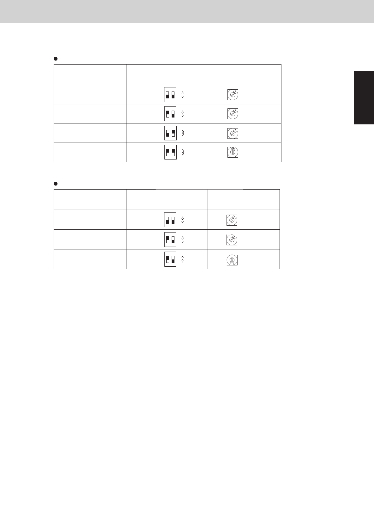
12. Outdoor Unit Control PCB
Table 1
Examples of refrigerant circuit (R.C.) address settings (required when link wiring is used) (SW1, SW2)
System address No.
System 1 (factory setting)
System 11
System 21
System 30
Table 2
Examples of the number of indoor units settings (SW3, SW4)
Number of indoor units
1 unit (factory setting)
11 units
15 units
System address (SW1)
(2P DIP switch)
Both OFF
1 ON
2 ON
Both ON
Indoor unit setting (SW3)
(2P DIP switch)
Both OFF
1 ON
1 ON
10 20
ON
ON
ON
ON
10 20
ON
ON
ON
Mini VRF SYSTEM
Control Functions - Outdoor unit
System address (SW2)
(Rotary switch)
ON
21
OFF
ON
21
OFF
ON
21
OFF
ON
21
OFF
Set to 1
Set to 1
Set to 1
Set to 0
Indoor unit setting (SW4)
(Rotary switch)
ON
21
OFF
ON
21
OFF
ON
21
OFF
Set to 1
Set to 1
Set to 5
5
1
The sub unit control P.C. board contains the same switches as the main unit control P.C. board for the number of indoor units, and
system address. However it is not necessary to set these switches.
1 - 35
Page 46
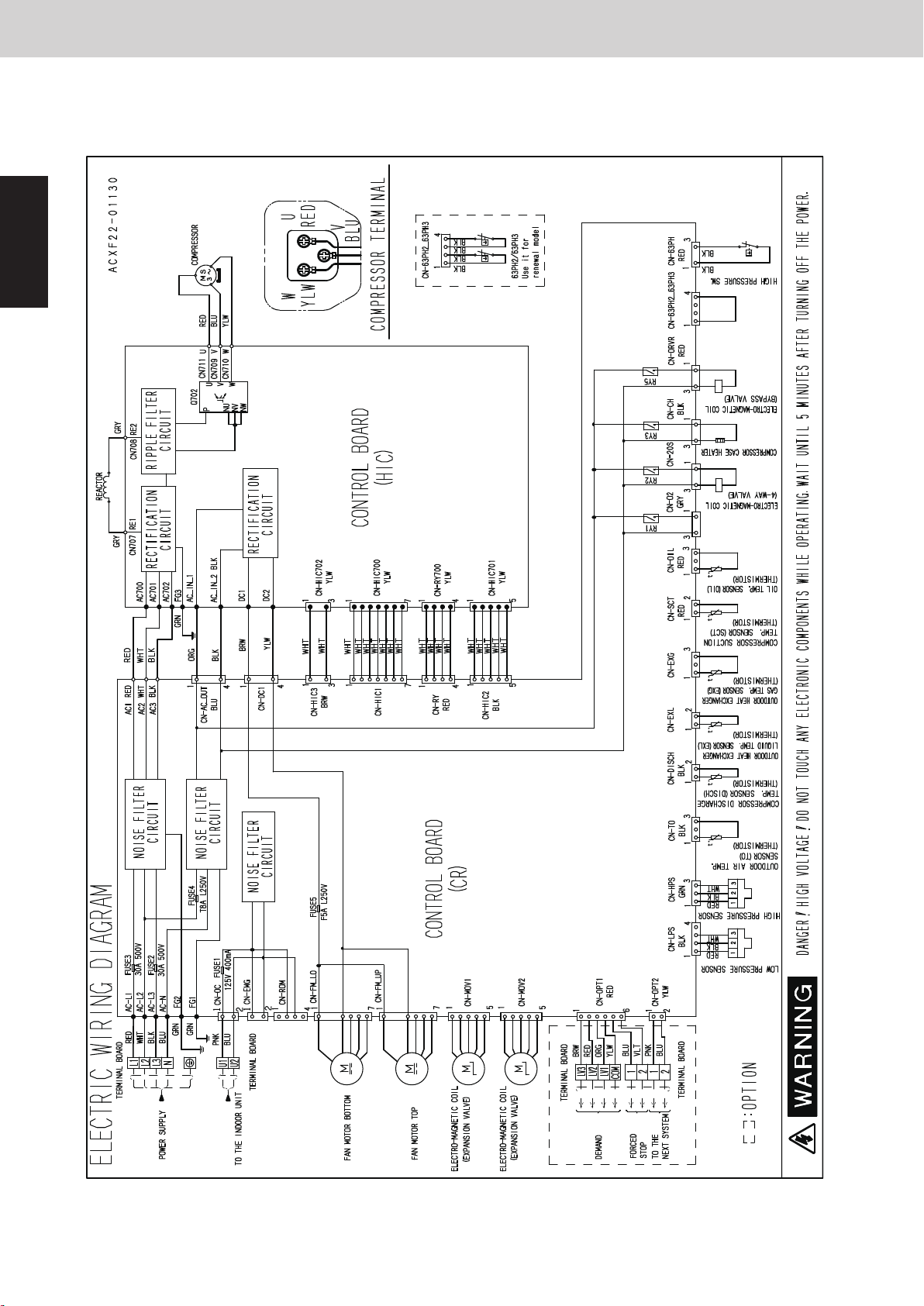
13. Electrical Data
(1) Electric Wiring Diagram U-8LE1R8(E), U-10LE1R8(E)
1
Mini VRF SYSTEM
Control Functions - Outdoor unit
1 - 36
Page 47

Mini VRF SYSTEM
Contents
Control Functions - Indoor Unit
2. CONTROL FUNCTIONS - Indoor Unit
1. Room Temperature Control .............................................. 2-2
2. Heating Standby ....................................................... 2-4
3. Automatic Fan Speed Control ............................................ 2-5
4. Indoor Unit MOV Control ................................................ 2-6
5. Drain Pump Control .................................................... 2-6
6. Automatic Heating / Cooling Control ...................................... 2-7
7. Discharge Air Temperature Control ....................................... 2-8
8. RAP Valve Kit Control ................................................... 2-8
9. Automatic Flap Control ................................................. 2-9
10. Filter Sign ............................................................ 2-9
11. Fan Control during Dry Mode ........................................... 2-10
2
12. Ventilation Fan Output ................................................. 2-11
13. T10 Terminal .......................................................... 2-11
14. Parameter ............................................................ 2-12
2 - 1
Page 48
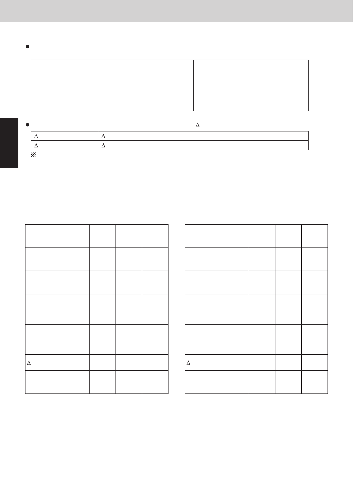
1. Room Temperature Control
Control Functions - Indoor Unit
1. Room Temperature Control
The body sensor or remote controller sensor detects temperature in the room. The detected temperature is
called the room temperature. The body sensor is the one contained in the indoor unit.
Body sensor is enabled Remote controller sensor is enabled
Set temp. Set temp. in remote controller Set temp. in remote controller
Detected temp. by
sensor
Room temp. Detected temp. by body sensor -
The thermostat is turned ON or OFF according to the following T.
T (Cooling) T = room temp. – set temp. (set temp. in remote controller)
2
T (Heating) T = set temp. – room temp.
Correction temperature (only during heating)
If the indoor unit is installed on the ceiling, temperature near the ceiling is higher than near the floor. When
the body sensor is enabled, lower temperature near the floor must be considered. To correct this difference in
temperature, the correction temperature is used.
The factory setting for the correction temperature is different depending on the model. See “14. Parameter”.
Detected temp. by body sensor Detected temp. by remote controller
sensor
Detected temp. by remote controller
*correction temp.
sensor
Mini VRF SYSTEM
Example: Cooling temperature correction
4-Way cassette (correction temperature: 0 degrees)
Body sensor is enabled
Set temp. in remote
controller
Detected temp. by
sensor
Detected temp. by
body sensor
Detected temp. by
remote controller
sensor
Room temp. = temp.
detected by body
sensor
T +2.0deg -0.5deg -1.0deg
28℃ 28℃ 28℃
30.0℃ 27.5℃ 27.0℃
30.0℃ 27.5℃ 27.0℃
30.0℃ 27.5℃ 27.0℃
30.0℃
=30.0
27.5℃
=27.5
27.0℃
=27.0
Example: Heating temperature correction
4-Way cassette (correction temperature: 4 degrees)
Body sensor is enabled
Set temp. in remote
controller
Detected temp. by
sensor
Detected temp. by
body sensor
Detected temp. by
remote controller
sensor
Room temp. = temp.
detected by body
sensor – 4 deg
T +7.0deg +2.0deg -1.0deg
20℃ 20℃ 20℃
17.0℃ 22.0℃ 25.0℃
17.0℃ 22.0℃ 25.0℃
13.0℃ 18.0℃ 21.0℃
13.0℃
=17.0-4
deg
18.0℃
=22.0-4
deg
21.0℃
=25.0-4
deg
ThermostatONThermostatONThermostat
OFF
ThermostatONThermostatONThermostat
OFF
2 - 2
Page 49
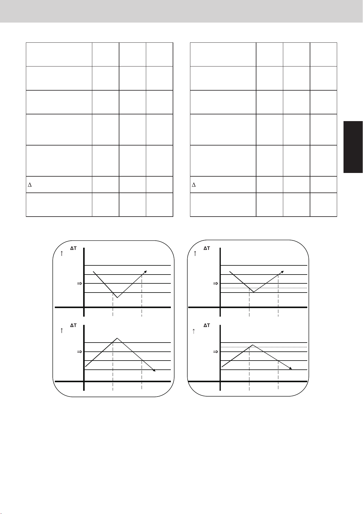
1. Room Temperature Control
Body sensor is enabled Remote controller sensor is enabled
Mini VRF SYSTEM
Control Functions - Indoor Unit
Remote controller sensor is enabled
Set temp. in remote
controller
Detected temp. by
sensor
Detected temp. by
body sensor
28℃ 28℃ 28℃
30.0℃ 27.5℃ 27.0℃
30.0℃ 27.5℃ 27.0℃
Detected temp. by
remote controller
30.0℃ 27.5℃ 27.0℃
sensor
Room temp. = temp.
detected by remote
controller sensor
30.0℃
=30.0
27.5℃
=27.5
27.0℃
=27.0
T +2.0deg -0.5deg -1.0deg
ThermostatONThermostat
OFF
Thermostat
OFF
Remote controller sensor is enabled
Set temp. in remote
controller
Detected temp. by
sensor
Detected temp. by
body sensor
20℃ 20℃ 20℃
17.0℃ 20.5℃ 21.0℃
21.0℃ 24.5℃ 25.0℃
Detected temp. by
remote controller
17.0℃ 20.5℃ 21.0℃
sensor
Room temp. = temp.
detected by remote
controller sensor
17.0℃
=17.0
20.5℃
=20.5
21.0℃
=21.0
T +3.0deg -0.5deg -1.0deg
ThermostatONThermostat
OFF
Thermostat
OFF
2
(deg)
+2
+1
Room temp.
Set temp.
-1
(deg)
-1
Room
temp.
Set temp.
+1
+2
Thermostat Thermostat
Cooling
ON ONOFF
Heating
ON ONOFF
(deg)
+2
+1
Room temp.
Set temp.
-0.5
-1
ThermostatThermostat
(deg)
-1
Room
temp.
-0.5
Set temp.
+1
+2
ON ONOFF
ON ONOFF
① The thermostat does not turn OFF for 3 minutes after it turns ON.
Cooling
Heating
② The thermostat does not turn ON 1 to 3 minutes after it turns OFF.
③ The thermostat does not turn OFF for 60 minutes during the test run mode. (Forced thermostat ON)
*However, the thermostat turns OFF if an alarm occurs.
2 - 3
Page 50
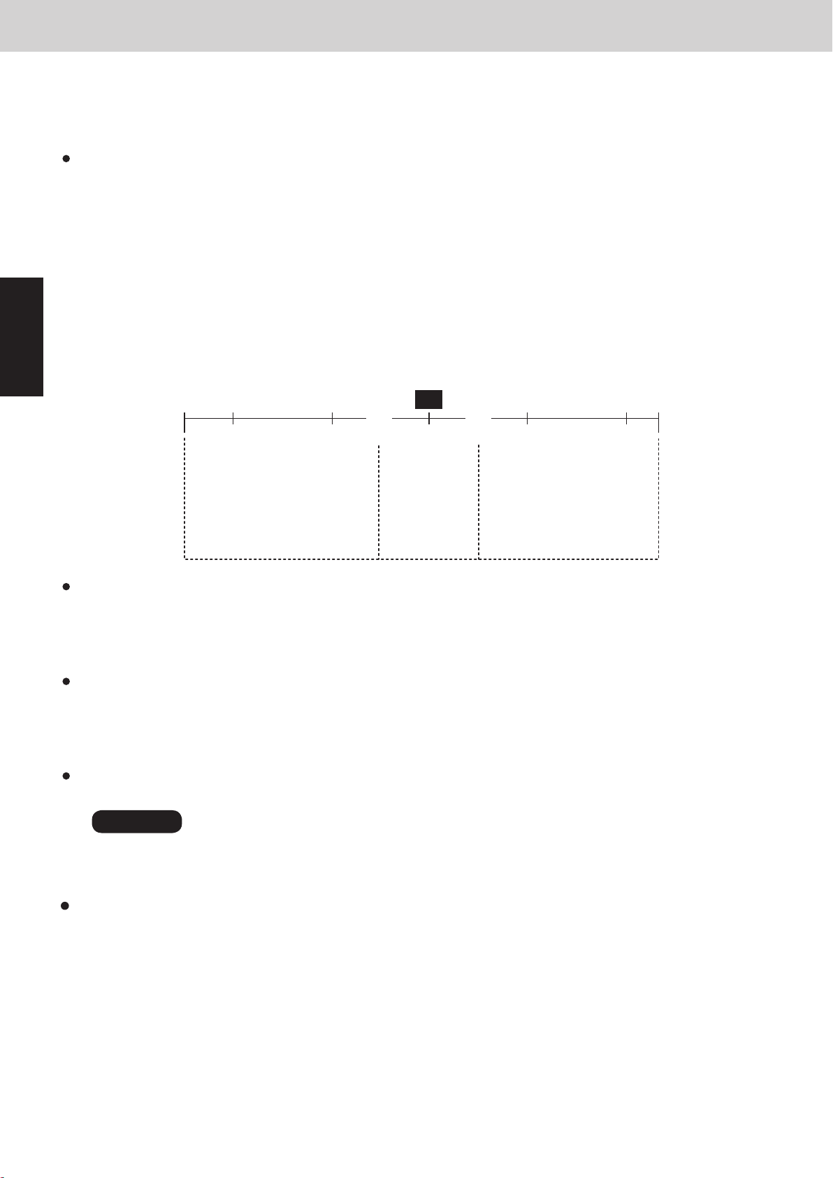
1. Room Temperature Control
2. Heating Standby
Control Functions - Indoor Unit
Mini VRF SYSTEM
< FRESH AIR INTAKE MODE (Type E2) >
Intake Air Temperature Control
This product brings outdoor fresh air into the building and adjusts and supplies the air with nearly current indoor temperature.
Automatic cooling and heating operation mode
Due to the temperature difference between the outdoor air and preset temperature in remote controller, cooling or heating
operation can be automatically selected.
In the case of group control, the setting is possible when all of the indoor units in the same refrigerant circuit consist of one
group.
Cooling operation mode : In case that the outdoor temperature is 5°C higher than the preset temperature in remote
①
controller.
Fan operation mode : In case that the outdoor temperature and preset temperature in remote controller are within
②
±5°C.
Heating operation mode : In case that the outdoor temperature is 5°C lower than the preset temperature in remote
③
2
Example: In case that the preset temperature in remote controller set at 20°C
controller.
Outdoor temperature (°C)
)5–()5–(
(+5)
20
15 25
(43)4030100
Heating operation mode
Discharge temperature
setting at 45°C
Fan operation
②③ ①
mode
Discharge
temperature
setting in a
range of
15 - 25°C
Cooling operation
mode
Discharge temperature
setting at 18°C
Cooling operation mode
It is recommended that the temperature setting in remote controller be more than 24°C.
If the intake air temperature is getting higher than the preset temperature in remote controller, the unit operates in cooling
mode. On the contrary, if the intake air temperature becomes lower than the preset temperature, the unit operates in fan
mode.
Heating operation mode
It is recommended that the temperature setting in remote controller be set at 16°C.
If the intake air temperature is getting lower than the preset temperature in remote controller, the unit operates in heating
mode. On the contrary, if the intake air temperature becomes higher than the preset temperature, the unit operates in fan
mode.
Fan operation mode
In the moderate climates, supply of fresh outdoor air can provide as passive cooling.
NOTE
In general, it is recommended that you set in the automatic cooling and heating operation mode.
2. Heating Standby
Refer to the indoor unit service manual.
2 - 4
Page 51
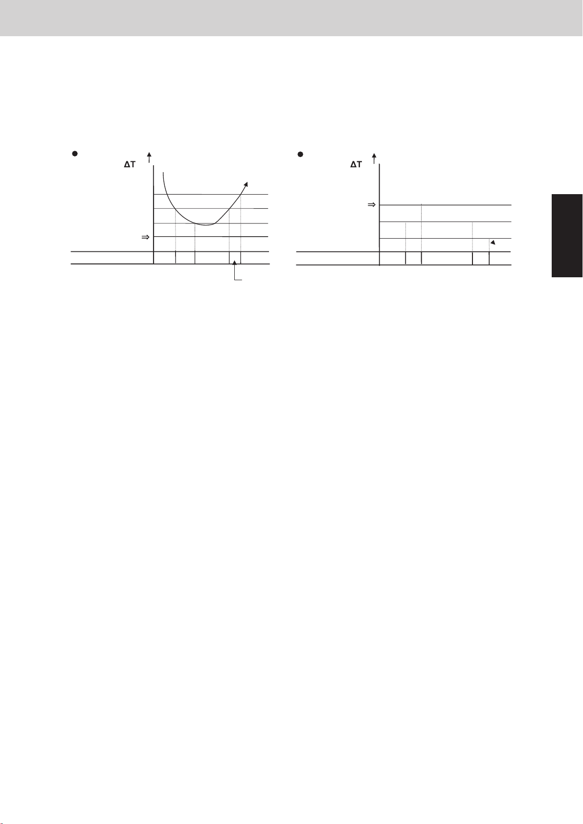
Mini VRF SYSTEM
Cooling
3. Automatic Fan Speed Control
3. Automatic Fan Speed Control
① The indoor fan mode is controlled as shown below during the automatic fan mode.
② The fan mode does not change for 3 minutes during cooling operation and 1 minute during heating
operation once it is changed.
③ The values in the parenthesis are when the remote controller sensor is enabled.
Heating
Control Functions - Indoor Unit
(deg)
+3
+2
+1
Set temp.
Indoor fan mode HH
(deg)
Set temp.
(-1)-2
(-2)-4
L
H
HH
H
Indoor fan mode
HH
H
L
HH
H
2
2 - 5
Page 52
4. Indoor Unit MOV Control
5. Drain Pump Control
4. Indoor Unit MOV Control
For details, see the Section 1.
The MOV is at 480 pulses in the following cases.
① At the time of factory shipment
② Just after the indoor unit power cord is connected.
5. Drain Pump Control
The drain pump operates in the following conditions.
① Cooling thermostat ON
② The float switch worked.
③ The drain pump may often operate for a while when the cooling thermostat turns OFF or the indoor
2
unit is stopped.
④ The drain pump can be turned on when the cooling thermostat is OFF if the setting is made to prevent
water collected in the drain pan for a long time. For details, see the item "5-2. Detailed Settings
Function" under the Section 5.
⑤ The indoor unit heat exchanger liquid temperature (E1) is less than 0˚C when the cooling thermostat
is OFF or the indoor unit is stopped.
Mini VRF SYSTEM
Control Functions - Indoor Unit
The drain pump operates for 20 minutes once it starts operating.
2 - 6
Page 53
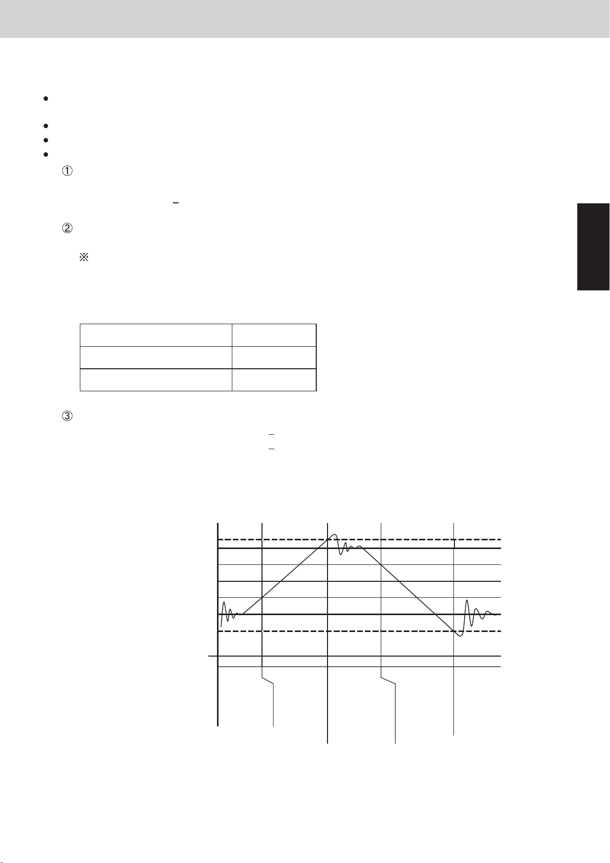
6. Automatic Heating / Cooling Control
6. Automatic Heating / Cooling Control
( )* : FRESH AIR INTAKE MODE (Type E2)
This function is only valid as long as one indoor unit is installed within one refrigerant system or all indoor
units are controlled within a group control.
When operating in a group control, the sub-indoor units become the same operation mode of the main unit.
As for the indoor units in a group control, install them in the same air conditioning circumstances.
Use the temperature sensor which is built-in sensor of the indoor unit.
The operating mode is selected according to the set temperature and room temperature when the
operation is started.
Room temperature
>
set temperature in remote controller – 1˚C (+ 5˚C)*
Room temperature < set temperature in remote controller – 1˚C (– 5˚C)* → Heating mode
The set temperature is corrected according to the operating mode. The correction temperature is +2
degrees in cooling mode and -2 degrees in heating mode at the time of factory shipment.
The correction value is different depending on the model. See “14. Parameter” for details.
Corrected cooling temperature – control temperature for cooling
Corrected heating temperature – control temperature for heating
Mini VRF SYSTEM
Control Functions - Indoor Unit
→ Cooling mode
2
When setting temperature in remote controller is 20˚C in the cooling mode (at shipment) :
Control temp. for cooling 22˚C (25˚C)*
Set temp. in remote controller 20˚C (20˚C)*
Control temp. for heating 18˚C (15˚C)*
Condition for mode change
Heating → Cooling: Room temperature > Control temperature for cooling + 0.5 degree
Cooling → Heating: Room temperature < Control temperature for heating -1.0 degree
When setting temperature in remote controller is 20˚C in the cooling mode :
Control temp. for cooling
Cooling thermostat OFF temp.
Heating thermostat OFF temp.
Control temp. for heating
Temp. for switching to heating
+2.5deg (+5.5deg)*Temp. for switching to cooling
+2deg (+5deg)*
+1deg (+4deg)*
Set temp. in remote controller
-1deg (-4deg)*
-2deg (-5deg)*
-3deg (-6deg)*
Heating
Heating thermostat OFF
The heating
thermostat OFF
continues for 10
minutes regardless
of temp. condition.
Then, the mode
changes to cooling.
For settings at the time of factory shipment, see “14. Parameter”.
2 - 7
Cooling
Cooling thermostat OFF
Heating
The cooling
thermostat OFF
continues for 10
minutes regardless
of temp. condition.
Then, the mode
changes to heating.
Page 54
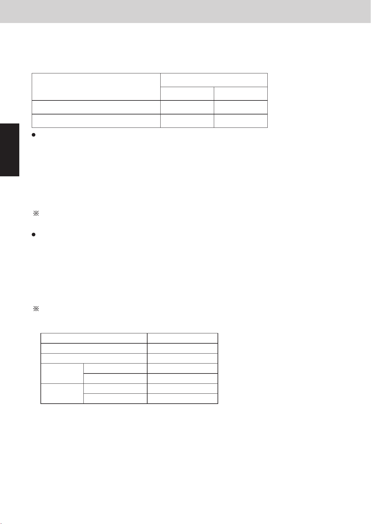
7. Discharge Air Temperature Control
8. RAP Valve Kit Control
7. Discharge Air Temperature Control
Discharge air temperature is controlled using the indoor unit discharge air temperature sensor. The discharge
air temperature is set in the EEPROM on the PCB. The setting is different depending on the model.
Discharge air temperature setting (at the time of factory shipment)
Indoor unit type
Y2, F2, M1, E2, K2 12˚C 50˚C
E2 (FRESH AIR INTAKE MODE) 18˚C 45˚C
Condition for Thermostat ON → OFF under discharge air temperature control
① Temperature less than “Discharge air temperature setting – 2˚C” is continuously detected for 20
2
minutes in cooling mode
② Temperature more than “Discharge air temperature setting + 2˚C” is continuously detected for 20
minutes in heating mode
③ Temperature less than “Discharge air temperature setting – 3.5˚C” is continuously detected for 7
minutes in cooling mode
④ Temperature more than “Discharge air temperature setting + 3.5˚C” is continuously detected for 7
minutes in heating mode
There is no priority order between the room temperature control and discharge air temperature control.
Mini VRF SYSTEM
Control Functions - Indoor Unit
Discharge air temperature setting
Cooling Heating
Relation between thermostat ON / OFF and room temperature control / discharge air temperature control
Thermostat turns OFF: Either room temperature control or discharge air temperature control satisfies
thermostat OFF condition.
Thermostat turns ON: Both of room temperature control and discharge air temperature control satisfy
thermostat ON condition.
8. RAP Valve Kit Control
The RAP valve kit is sometimes used in the 2WAY system.
The RAP valve kit prevents refrigerant from collecting in the indoor heat exchanger when the indoor unit is
stopped. The following table shows the RAP valve kit operation.
Operating mode RAP valve kit
Stopped OFF
Fan OFF
Cooling
Heating
Thermostat ON OFF
Thermostat OFF OFF
Thermostat ON ON
Thermostat OFF OFF
2 - 8
Page 55
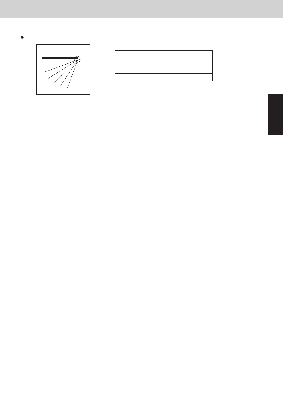
9. Automatic Flap Control
10. Filter Sign
9. Automatic Flap Control
The flap position can be selected from 5 positions.
Operating mode Flap position
F0
F1
F2
F3
F4
F5
① The flap moves to the following position automatically when the indoor unit is stopped.
F0 (close): Types K1, K2, T2, D1, U1, Y2
F5: Models other than the above
② The flap closes once and moves to the set position when the operating mode is changed.
※ If the flap position cannot be adjusted because of a problem, only the swing operation can be
used. Check the flap and flap motor.
※ The swing operation can be set for the flap.
Cooling / Dry F1・F2・F3
Fan F1・F2・F3・F4・F5
Heating F1・F2・F3・F4・F5
Control Functions - Indoor Unit
Mini VRF SYSTEM
2
10. Filter Sign
① When accumulated operating time of the indoor unit reaches the set time, the filter sign appears on
the remote controller. Clean the filter.
See page 5-5.
② After cleaning the filter, press the filter button on the remote controller once. The filter sign turns off.
2 - 9
Page 56
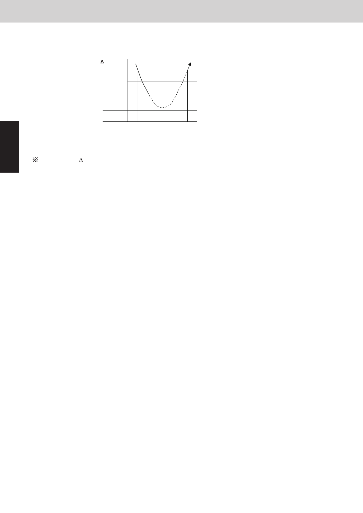
11. Fan Control during Dry Mode
AA
11. Fan Control during Dry Mode
The fan control during dry mode is as follows.
T (deg)
+1
Set temp. in remote controller
-1
A: Fan mode set in the remote controller
2
B: Fan mode is L during thermostat ON, LL during thermostat OFF
For details on T, see “1. Room Temperature Control”.
Mini VRF SYSTEM
Control Functions - Indoor Unit
BFan mode
2 - 10
Page 57

12. Ventilation Fan Output
13. T10 Terminal
12. Ventilation Fan Output
The output of ventilation turns ON when the indoor unit turns ON. Also, when the indoor unit turns OFF,
the output of the ventilation turns OFF.
The ventilation fan can also be turned ON and OFF using the ventilation button on the remote controller.
Refer to the operating instractions supplied with the remote controller.
To enable this function, set the indoor EEPROM DN31 to “0001” in advance.
13. T10 Terminal
Using the T10 terminal, each indoor unit can be operated or stopped separately. Also, operating condition can be
checked.
Control Functions - Indoor Unit
Mini VRF SYSTEM
2
2 - 11
Page 58
14. Parameter
14. Parameter
Type Model
Correction temp. (heating)
Mini VRF SYSTEM
Control Functions - Indoor Unit
Heat / cool switching
correction temp.
(automatic heat / cool)
2
Setting at time of factory
shipment
U1 4-Way Cassette 4 deg 2 deg
Y2 4-Way Cassette 60×60 4 deg 2 deg
L1 2-Way Cassette 4 deg 2 deg
D1 1-Way Cassette 4 deg 2 deg
F2 Low Silhouette Ducted 4 deg 2 deg
T2 Ceiling 4 deg 2 deg
K1 Wall Mounted 2 deg 2 deg
K2 Wall Mounted 3 deg 2 deg
M1 Slim Low Static Ducted 4 deg 2 deg
High Static Pressure Ducted 4 deg 2 deg
E2
High Static Pressure Ducted
(FRESH AIR INTAKE MODE)
0 deg 5 deg
Setting at time of factory
shipment
P1 Floor Standing 0 deg 2 deg
R1 Concealed Floor Standing 0 deg 2 deg
2 - 12
Page 59

Mini VRF SYSTEM
Contents
Outdoor Unit Repair Procedures
3. OUTDOOR UNIT REPAIR PROCEDURES
1. Removing Panels ....................................................... 3-2
2. Discharging Compressor Oil ............................................. 3-3
3. Recovering Refrigerant .................................................. 3-4
4 Checking for Leakage After Repair ........................................ 3-9
5. Evacuating System .................................................... 3-10
6. Charging Compressor Oil ............................................... 3-11
7. Pumping Out Refrigerant from Outdoor Unit ............................... 3-15
8. Compressor .......................................................... 3-18
3
3 - 1
Page 60

1. Removing Panels
Mini VRF SYSTEM
Outdoor Unit Repair Procedures
3
CAUTION
(1) Front panel removal
• Remove the front panel (remove 2 screws).
(2) Cover A removal
• Remove the cover A (remove 1 screw).
Be sure to turn off the power before maintenance. When the power is turned off,
wait for 5 minutes without any work. Then start working.
Front panel
Cover A
Fig. 1
3 - 2
Page 61
Mini VRF SYSTEM
2. Discharging Compressor Oil
2-1. Discharging Oil in Compressor
Recover the refrigerant in the outdoor unit following the procedures in “3. Recovering Refrigerant.” Remove the
compressor and discharge the oil in it. See the section “8. Compressor” for detailed procedures.
2-2. Checking the Oil
Acceptance/rejection criteria for the oil
Condition of
refrigeration cycle
Normal Light chestnut None 0.02 or less 3.5 or less
Abnormal overheat-
operation
Motor burnout
* It is difficult to measure the total acid value in the field, therefore oil hue and odor are the rule of thumb.
Checking for carbon deposits and abrasive metal powder can additionally be used to assess the system condition.
Color Odor Total acid value Hue
Brownish
Brownish /
blackish
Condition of oil Judgment criteria for changing oil*
Smells somewhat
(not as strong as below)
Pungent / burnt odor
Outdoor Unit Repair Procedures
over 0.06 over 4.0
Changing the oil and system cleaning
with dry-cores are necessary.
Changing the oil and system cleaning
with dry-cores are necessary.
3
3 - 3
Page 62
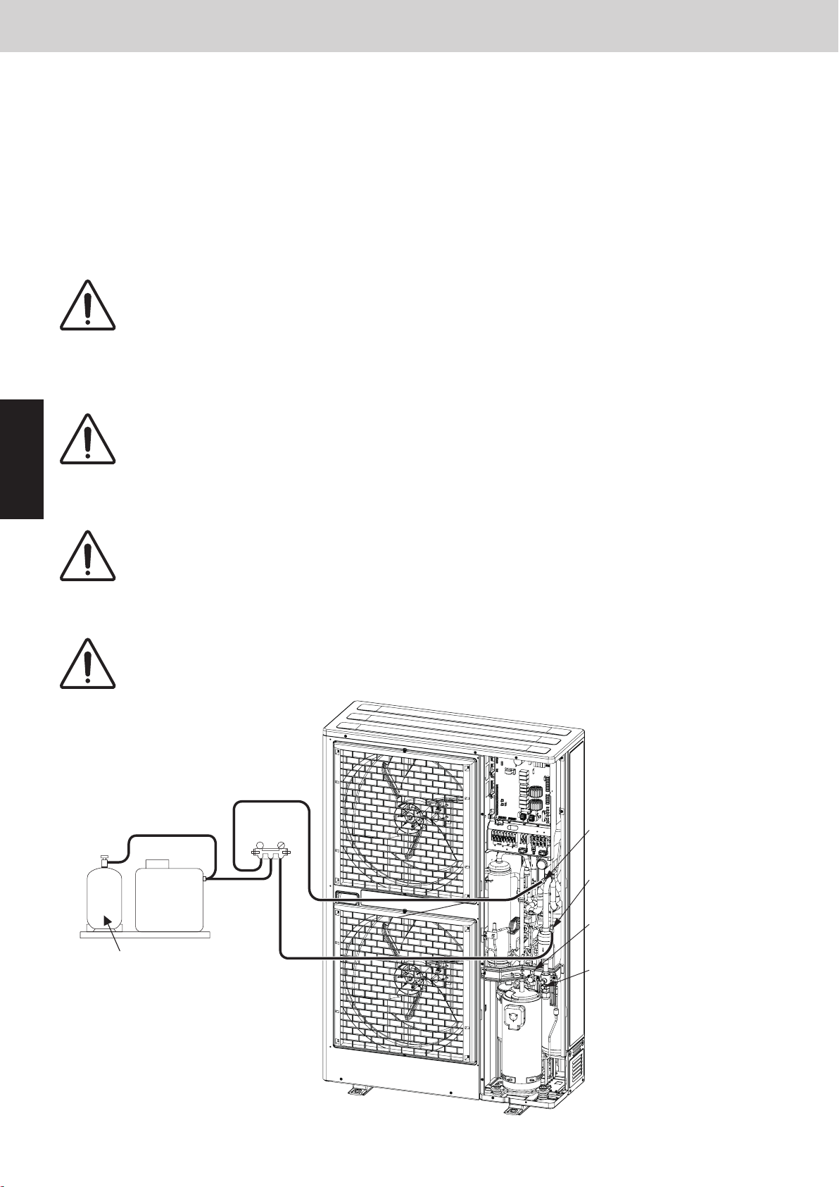
Mini VRF SYSTEM
3. Recovering Refrigerant
The following equipment and tools are required:
Jumper wire with clips, adjustable wrench, set of manifold gauge valves specially designed for refrigerant R410A
only, vacuum pump, refrigerant recovery unit, pre-purged refrigerant cylinder for recovery, flathead screwdriver, and
outdoor unit maintenance remote controller.
3-1. Refrigerant Recovery Procedures (from outdoor unit)
(1) Turn off the power of the outdoor unit beforehand (at power mains).
(2) Fully close each service valve on the liquid tube and gas tube of the outdoor unit.
(3) Connect the outdoor unit’s high-pressure and low-pressure outlet ports with the Hi and Lo sides of the mani-
fold gauge valves using hoses. (Fig. 2)
The remaining refrigerant in the faulty outdoor unit may create internal pressure.
CAUTION
(4) Connect the manifold gauge valves, refrigerant recovery unit, and recovery cylinder using hoses. To avoid the
entry of air into the refrigerant tubing, carry out this connection work carefully. (Fig. 2)
CAUTION
3
Before connecting hoses, be sure to confirm that each of the manifold gauge
valves is tightly closed. Note that the connection ports employ Schrader-type
push-to-release valves.
For detailed procedures such as connecting the refrigerant recovery unit with the
recovery cylinder and methods used for recovery, follow the specific instructions
that came with the refrigerant recovery unit.
Outdoor Unit Repair Procedures
(5) Locate the AP pin on the control PCB in the faulty outdoor unit and short them using the clips of
the jumper wire. Then restore electrical power to the outdoor unit.
By short-circuiting the AP pin, each solenoid valve in the outdoor unit is forcibly
CAUTION
opened as soon as power comes on, which releases all remaining refrigerant into
the recovery cylinder. Since neglecting this procedure may leave some refrigerant
in the system, it is important that you carry out this step.
(6) Carry out refrigerant recovery.
To determine the completion of refrigerant recovery, follow the instructions that
CAUTION
Refrigerant
recovery unit
Refrigerant recovery cylinder
came with the refrigerant recovery unit.
Manifold
gauge
Lo Hi
Low-pressure outlet port
(for ø7.94mm-dia connector)
High-pressure outlet port
(for ø7.94mm-dia connector)
Liquid tube service port
(for ø7.94mm-dia connector)
Gas tube service port
(for ø7.94mm-dia connector)
Fig. 2
3 - 4
Page 63
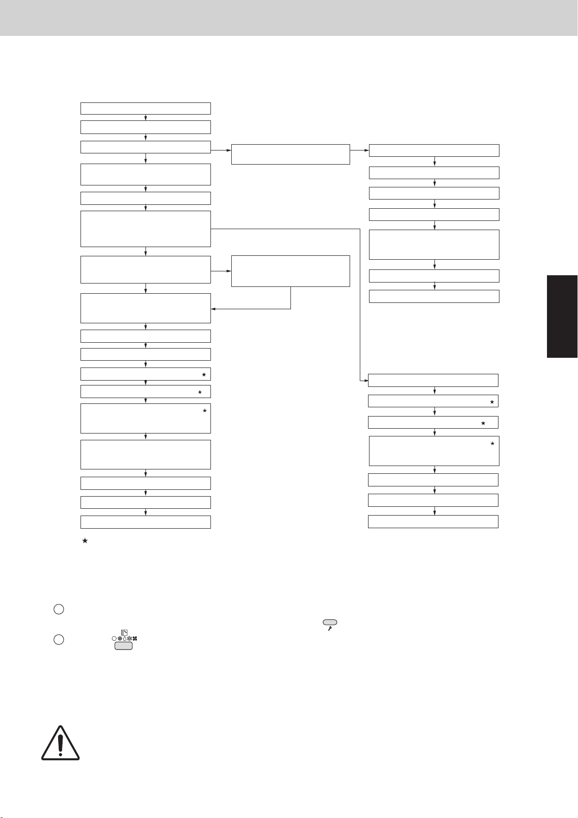
Mini VRF SYSTEM
3. Recovering Refrigerant
3-2. Refrigerant Recovery Procedures (Indoor Unit)
The flowchart below shows the refrigerant recovery procedures you must follow when replacing or repairing the
indoor unit due to trouble in the refrigerant circuit.
START
3-2-1. Cooling operation (for all units)
Outdoor Unit Repair Procedures
Ball valve is provided in the indoor unit
YES
3-2-2. Refrigerant recovery
procedures (1)
Turn off all equipment in system
When replacing or repairing a faulty
unit, let other normal indoor units run
(excluding indoor unit where refrigerant
is recovered)
YES
Power can independently be turned off
for indoor unit where refrigerant is
recovered
YES
Change controllable number of indoor
units (including changes in group
control and integrated-control settings)
Other indoor units can operate normally
Replace or repair faulty unit
Check for leakage in repaired unit
Evacuate air from repaired unit
Charge refrigerant in repaired unit
(Amount of charge should equal that
recovered by refrigerant recovery unit)
NO
NO
NO
3-2-3. Refrigerant recovery
procedures (2)
Modify power to permit turning off
power to refrigerant-recovered
indoor units independently
Turn off all equipment in system
Replace or repair faulty unit
Check for leakage in repaired unit
Evacuate air from repaired unit
Charge refrigerant in repaired unit
(Amount of charge should equal that
recovered by refrigerant recovery unit)
Ready for operation
END
3
Replace or repair faulty unit
Check for leakage in repaired unit
Evacuate air in repaired unit
Change controllable number of indoor
units (including changes in group
control and integrated-control settings)
Open ball valve
Ready for normal operation
END
Service work performed on indoor units is done simultaneously using the service ports at the liquid (narrow tube) side and the
gas (wide tube) side ball valves. Refer to each section in the “Installation Instructions” on refrigerant charging, leak checking, and
evacuation procedures.
Charge refrigerant in repaired unit
(Amount of charge should equal that
recovered by refrigerant recovery unit)
Open the ball valve
Ready for normal operation
END
3-2-1. Cooling operation (for all units)
(1) If the remote controller is used for maintenance of the outdoor unit
1 Connect the outdoor unit maintenance remote controller to the RC connector on the outdoor unit control
PCBs. Then start a test run of all units. (Press and hold the (CHECK) button for 4 seconds or longer.)
2 Press the
See the section 4 for the detail of the outdoor maintenance remote controller operation. It may be possible to
determine whether operation is cooling or heating by touching the gas tubing.
Cooling : low temperature (20℃ or lower)
Heating: high temperature (60℃ or higher)
A
(MODE) button and change to cooling operation and ensure that the cooling is performed.
CAUTION
The gas tubing becomes hot (60°C or higher) in heating mode. Be careful so as
not to be burnt when touching the tubing.
3 - 5
Page 64

Mini VRF SYSTEM
3. Recovering Refrigerant
(2) If the remote controller is not available for maintenance of the outdoor unit
1 Short-circuit the MODE pin ("COOL" side) on the outdoor unit control PCB.
2 Short-circuit the CHK pin on the PCB to start test run operation.
3-2-2. Refrigerant recovery procedures (1) (using indoor unit ball valve)
(1) If a ball valve with a service port has been provided in the indoor unit as shown in Fig. 3, follow the instructions
given in (2) through (6) below. If the service port is instead located in the outdoor side, follow the instructions in
“3-2-3. Refrigerant recovery procedures (2).”
(2) After running the unit in Cooling mode for about 5 minutes as described in “3-2-1. Cooling operation (for all
units),” fully close the liquid tube ball valve.
(3) Run the unit in Cooling mode for 10 to 20 minutes more.
(4) Fully close the gas tube ball valve, and stop the operation of all units.
(5) Use hoses to connect the manifold gauge valves, refrigerant recovery unit, and refrigerant recovery cylinder
with each other. (Fig. 3) Do each connection quickly to prevent air from entering the tubing.
Remaining refrigerant may create internal pressure, therefore care should be
CAUTION
taken when connecting the hoses.
Outdoor Unit Repair Procedures
(6) Recover the remaining refrigerant from the indoor unit using the refrigerant recovery unit.
3
NOTE
To determine completion of refrigerant recovery, follow the instructions that came with the refrigerant recovery unit.
Manifold
gauge
Hi Lo
Refrigerant
recovery unit
Refrigerant
recovery cylinder
Gas tube
Outdoor unit
Liquid tube
Ball valve
(field supply)
Service port
Indoor unit
Fig. 3
3 - 6
Page 65
Mini VRF SYSTEM
3. Recovering Refrigerant
3-2-3. Refrigerant recovery procedures (2): Indoor unit with no ball valve equipped
Refrigerant in all indoor units and the refrigerant tubing circuit can be pumped into the outdoor unit. The maximum
refrigerant storage capacity per a single outdoor unit is approx. 6.6 kg. Thus, in order to collect all refrigerant from
the system, a separate refrigerant recovery unit is necessary. Follow these procedures to correctly perform pump
down.
Perform work correctly, according to the work procedures given below.
1 Connect the manifold gauge to the high- and low-pressure outlet ports on the outdoor unit where pump down
will be performed. Be sure that no air enters the tubing at this time.
2 Follow the instructions in “3-2-1. Cooling operation (for all units)” and operate all units in Cooling mode for
approximately 10 minutes. Then fully close the liquid tube valve on the outdoor unit where pump down will be
performed.
3 When the high-pressure gauge reaches 2.8 MPa or higher, or the low-pressure gauge reaches 0.5 MPa or
below, at the outdoor unit where pump down is being performed, press the ON/OFF button on the outdoor
unit maintenance remote controller to stop operation at all units. Then immediately fully close the gas tube
valve on the outdoor unit where pump down is being performed.
* If the outdoor unit maintenance remote controller is unavailable, short-circuit the STOP pin.
4 Using hoses with Schrader-type push-to-release valves, connect the manifold gauge valves to the gas tube
service port, the liquid tube service port to undergo pump down. (Fig. 4)
Outdoor Unit Repair Procedures
CAUTION
5 Use hoses to connect the manifold gauge valves, refrigerant recovery unit, and refrigerant recovery cylinder.
Quickly connect each part to prevent air from entering the tubing.
6 Recover remaining refrigerant from the inter-unit tubing and indoor units using the refrigerant recovery unit.
NOTE
To determine the completion of refrigerant recovery, follow the instructions that came with the refrigerant recovery unit.
Remaining refrigerant in the system may cause internal pressure. Check that each
valve on the manifold gauge is tightly closed. A Schrader-type push-to-release
valve is provided for each connection port.
3
3 - 7
Page 66
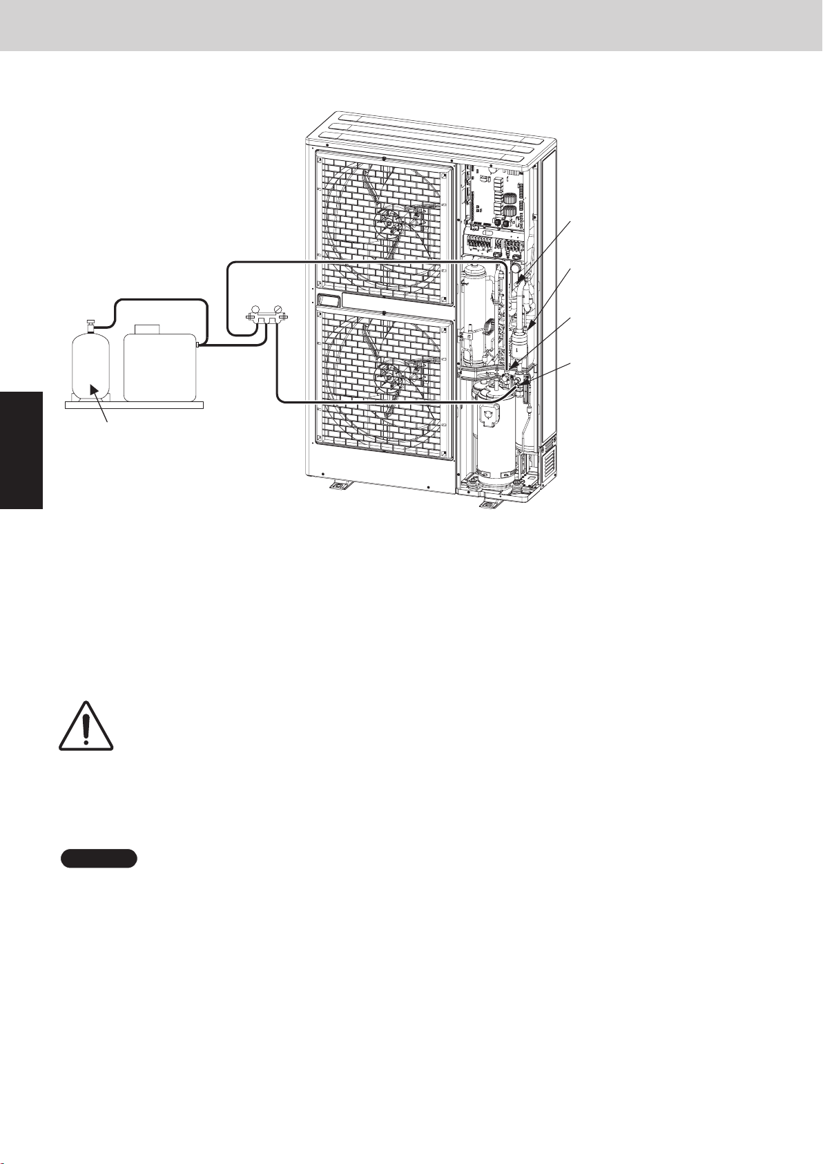
3. Recovering Refrigerant
Mini VRF SYSTEM
Outdoor Unit Repair Procedures
Low-pressure outlet port
(for ø7.94mm-dia connector)
High-pressure outlet port
(for ø7.94mm-dia connector)
Liquid tube service port
(for ø7.94mm-dia connector)
Gas tube service port
(for ø7.94mm-dia connector)
Refrigerant
recovery unit
Refrigerant recovery cylinder
Manifold
gauge
Lo Hi
3
Fig. 4
3-3. Refrigerant recovery from Entire System
(1) Turn off power to the outdoor unit.
(2) Short-circuit the AP pin on the outdoor control PCB, then supply power to the outdoor unit.
* By short-circuiting the AP pin and supplying power to the outdoor unit, the solenoid valve is forcibly opened
and all remaining refrigerant can be recovered.
(3) Connect the manifold gauge to the high- and low-pressure outlet ports (Schrader-type valves) on the outdoor
unit. (Fig. 4)
CAUTION
(4) Connect the manifold gauge valves, refrigerant recovery unit, and refrigerant recovery cylinder. Quickly connect
each part to prevent air from entering the tubing.
(5) Check that each service valve of the gas tube and liquid tube for the outdoor unit has opened, then perform
refrigerant recovery.
NOTE
To determine the completion of refrigerant recovery, follow the instructions that came with the refrigerant recovery unit.
Remaining refrigerant may create internal pressure, therefore care should be
taken when connecting the hoses.
3 - 8
Page 67
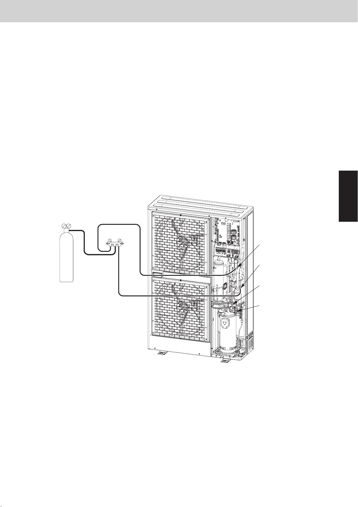
Mini VRF SYSTEM
4. Checking for Leakage After Repair
4-1. Pressure Check for Leakage of Outdoor Unit
After completing repair of the outdoor unit, carry out the following leakage check.
(1) Check that all service valves for gas tube and liquid tube in the repaired outdoor unit (units necessary to carry
out the pressurized leak check) are fully closed.
(2) Connect the manifold gauge valves to the high- and low-pressure outlet ports of the outdoor unit.
(3) Feed nitrogen gas into the circuit until 3.8 MPa pressure is reached. If it is apparent that the nitrogen gas is not
entering the repaired section, interrupt the feeding. Short-circuit the AP pin on the outdoor unit control PCB,
turn on power to run the outdoor unit, then resume feeding nitrogen.
(4) Apply soapy water to the repaired part (such as a newly brazed part), and briefly inspect for any leakage. If
there are any leaks, bubbles will show on the tubing surface.
* To continue the air-tight check after the brief leak inspection, turn on power while short-circuiting the AP pin.
Again feed nitrogen gas to obtain a system pressure of 3.8 MPa. Then measure both the outdoor ambient
temperature and the pressure in the system. Leave the system in this state for 1 full day and night, and again
measure the outdoor ambient temperature and pressure (to determine any reduced values). During the
inspection, it is recommended that an awning or cover be used to shield the unit in case of rain. If no problem
is found, purge all nitrogen from the system.
Outdoor Unit Repair Procedures
Nitrogen gas
3
Manifold gauge
Lo Hi
Low-pressure outlet port
(for ø7.94mm-dia connector)
High-pressure outlet port
(for ø7.94mm-dia connector)
Liquid tube service port
(for ø7.94mm-dia connector)
Gas tube service port
(for ø7.94mm-dia connector)
Fig. 5
4-2. Checking for Leakage in Refrigerant Tubing Between Indoor and Outdoor Units
Refer to the “Installation Instructions” that came with the outdoor unit.
3 - 9
Page 68
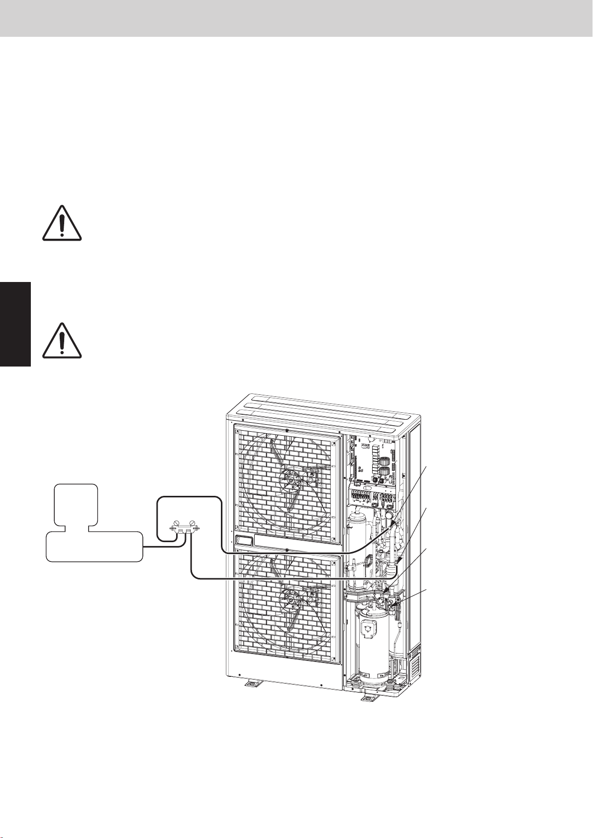
Mini VRF SYSTEM
5. Evacuating System
This procedure is carried out to ensure there is no remaining refrigerant or other gases (nitrogen, etc.) in the
repaired outdoor unit and tubing.
5-1. Evacuating Repaired Outdoor Unit
(1) Check that each service valve of the gas tube and liquid tube in the outdoor unit are fully closed.
(2) Connect the manifold gauge valves to the high-pressure and low-pressure sensor outlets of the outdoor unit.
(Fig. 6)
(3) Connect the manifold gauge valves to the vacuum pump.
* If the AP pin on the outdoor control PCB has already been short-circuited, step (4) is not necessary.
(4) Turn off power to the repaired outdoor unit and short-circuit the AP pin on the outdoor control PCB.
By short-circuiting the AP pin and turning on power to the outdoor unit, all
CAUTION
(5) Turn the power ON at the outdoor unit where vacuum will be applied. Then run the vacuum pump and continue
evacuation until the vacuum condition falls to less than –101kPa {–755 mmHg, 5 Torr}.
electronic valves in the outdoor unit are forcibly opened and any remaining
nitrogen gas can be recovered. Failure to perform this procedure may result in
nitrogen gas remaining in the refrigerant circuit and causing operating problems.
Therefore, never skip this step.
Outdoor Unit Repair Procedures
3
CAUTION
Vacuum pump
To ensure proper evacuation, refer to the operating instructions that came with the
vacuum pump.
Low-pressure outlet port
(for ø7.94mm-dia connector)
Manifold gauge
Lo Hi
High-pressure outlet port
(for ø7.94mm-dia connector)
Liquid tube service port
(for ø7.94mm-dia connector)
Gas tube service port
(for ø7.94mm-dia connector)
Fig. 6
5-2. Evacuating Refrigerant Tubing Between Indoor and Outdoor Units
For details, refer to the “Installation Instructions” that came with the outdoor unit.
3 - 10
Page 69
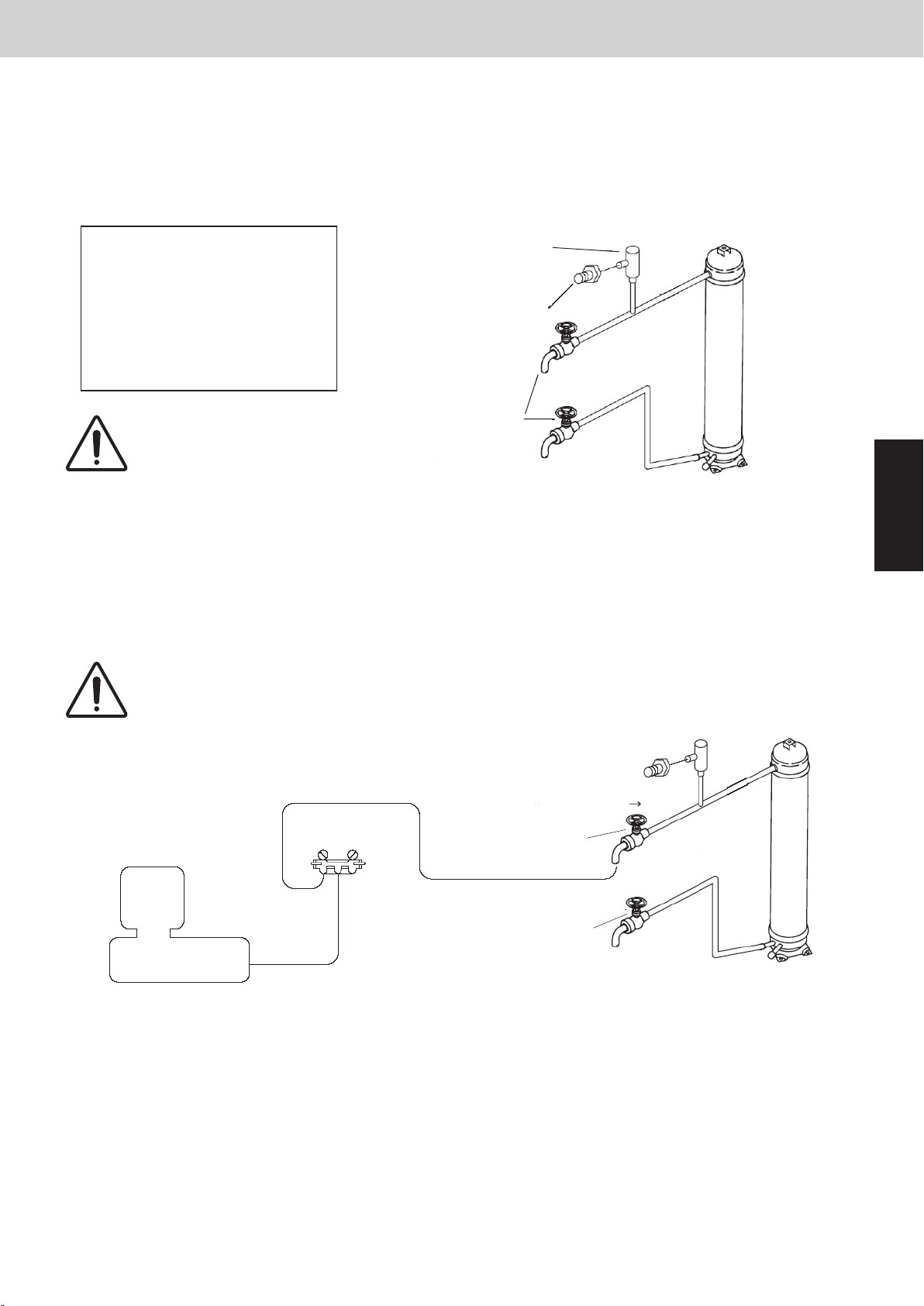
Mini VRF SYSTEM
6. Charging Compressor Oil
6-1. If Refrigerant Has Already Been Charged to Outdoor Unit
Be sure to use an exclusive oil-charging tank for charging compressor oil. Prior to charging, carry out vacuum drying
inside the tank and take care that no air (in the form of bubbles) is permitted to enter the tank.
The oil charging procedures are given below.
*The receiver tank used for maintenance may be used as an exclusive oil-charging tank.
Outdoor Unit Repair Procedures
When installing the oil-charging
(DPR : CV6230817937)
tank to the refrigerant system to
serve as a safety bypass circuit
for refrigerant, connect it to the
Nipple
gas tube service port carefully to
avoid releasing refrigerant into the
atmosphere.
Perform oil charging
CAUTION
work carefully so that no
Packless valve
(Receiver-tank:
CV6380152988)
liquid refrigerant enters
the charging tank.
(1) Evacuation drying in oil-charging tank
With the lower side valve fully closed, open the upper side valve and connect it to the vacuum pump via the
manifold gauge valves as shown below. Run the vacuum pump and evacuate the tank until the pressure falls to
below –101kPa {–755mmHg, 5 Torr} for the evacuation drying. After the evacuation drying is finished, fully close
the upper valve. Next, fully close the manifold gauge valves and stop the vacuum pump.
To ensure proper evacuation, refer to the operating instructions that came with the
CAUTION
vacuum pump.
3
Open Close
Vacuum pump
Manifold gauge
Lo
Hi
Upper side
valve
Close
Lower side
valve
(2) Charging compressor oil into oil-charging tank
Connect a piece of pipe to the lower valve and then insert the other end deeply into the bottom of the oil container. Make sure you avoid letting any air be sucked into the tube. Next, run the vacuum pump and open the
manifold gauge valves, then open the upper and lower valves to begin charging oil into the charging tank.
3 - 11
Page 70
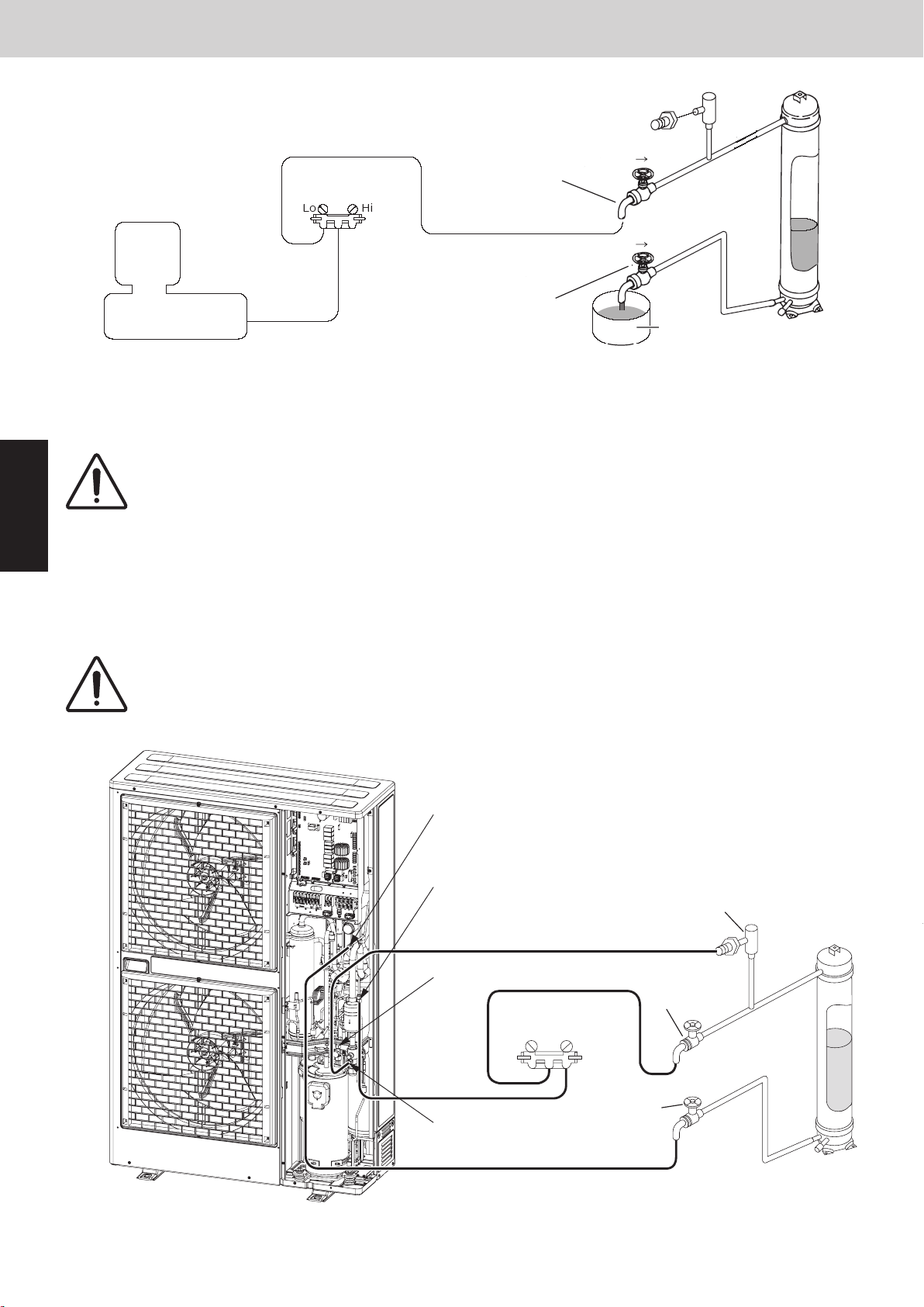
Mini VRF SYSTEM
2WAY SYSTEM
Outdoor Unit Repair Procedures
7. Charging Compressor Oil
Next, follow the instructions in “3-2-1. Cooling operation (for all units)” at the outdoor unit where oil will be charged,
and start cooling operation at all units. After the operating conditions were stabilized, open each valve (Hi-side
NOTE
To determine the completion of refrigerant recovery, follow the instructions that came with the refrigerant recovery unit.
When this is done, the refrigerant pressure from operation forces the oil out of the oil charge tank, and oil is charged
into the outdoor unit from the low-pressure outlet port. Occasionally close the upper valve on the top of the oil charge
tank (only this valve) and shake the tank to check the amount of remaining oil.
(1) Open the valve on the high-pressure side of the manifold gauge.
(2) Open the upper valve.
(3) Open the lower valve.
manifold gauge, upper valve and lower valve) in sequence as follows.
Operating valve
Hi-side
manifold
gauge
Lo-side
manifold
gauge
Upper
valve
Process
Oil
charging
Oil charge
completed
Refrigerant
recovery
(oil-charging
tank inside)
Open
Close*
Close
Close
(No connection)
Close
(No connection)
Open
(Connect to
refrigerant
recovery tank)
Open
Open
Open
Open
Close after
approx. 60
seconds
Close
Lower
valve
Completing oil-charging
To terminate the oil charging work, do as follows:
To end the charge process, first close the valve on the Hi-side manifold gauge. Then wait approximately 60
seconds in order to vaporize the refrigerant in the charge tank. Then fully close the lower valve.
Refrigerant recovery (oil-charging tank inside)
Finally, connect the refrigerant recovery unit to the Lo-side manifold gauge, shut down all indoor and outdoor units,
and then recover the remaining refrigerant in the oil-charging tank. Perform these procedures quickly and securely
so that no air can enter them. Then, charge the necessary amount of new refrigerant by referring to the “Installation
Instructions” that came with the outdoor unit.
(3)
Lower valve
Manifold gauge
Lo Hi
(1)
DPR
(2)
Upper valve
Connect from here to
refrigerant recovery unit
Fig. 8
Gas tube service port
(for ø7.94mm-dia connector)
Low-pressure outlet port
(for ø7.94mm-dia connector)
High-pressure outlet port
(for ø7.94mm-dia connector)
Liquid tube service port
(for ø7.94mm-dia connector)
6. Charging Compressor Oil
Manifold gauge
Vacuum pump
When the predetermined amount of oil has been charged into the oil-charging tank, immediately close the lower
valve. Next, run the vacuum pump until the system pressure reaches lower than -101kPa {-755mmHg, 5 Torr}.
Close the upper valve and then, stop the vacuum pump.
Do this operation quickly because compressor oil easily absorbs moisture from the
CAUTION
air.
Upper valve
Lower valve
Outdoor Unit Repair Procedures
Close Open
Close Open
Oil
3
(3) Charging compressor oil into outdoor unit
Connect the lower valve to the low-pressure outlet (with Schrader-type push-to-release valve) in the outdoor
unit to be oil-charged, and then connect the high-pressure outlet (with push-to-release valve) to the upper valve
via the manifold gauge valves (at Hi-pressure gauge side). In addition, connect the gas tube service port (with
push-to-release valve) to the DPR (Discharge Pressure Regulator). Carry out the connection work quickly to
avoid letting air enter the tube.
• The hoses may be subject to internal pressure from the refrigerant inside the outdoor
CAUTION
unit. A Schrader-type push-to-release valve is provided at each connection port.
• Since the DPR valve opens at pressures of 2.5 MPa and above, be sure to connect the
DPR to the gas tube service port (low-pressure side).
Low-pressure outlet port
(for ø7.94mm-dia connector)
High-pressure outlet port
(for ø7.94mm-dia connector)
Liquid tube service port
(for ø7.94mm-dia connector)
Manifold gauge
Lo Hi
DPR
Upper valve
Close
Gas tube service port
(for ø7.94mm-dia connector)
Lower valve
Close
Fig. 7
3 - 12
Page 71
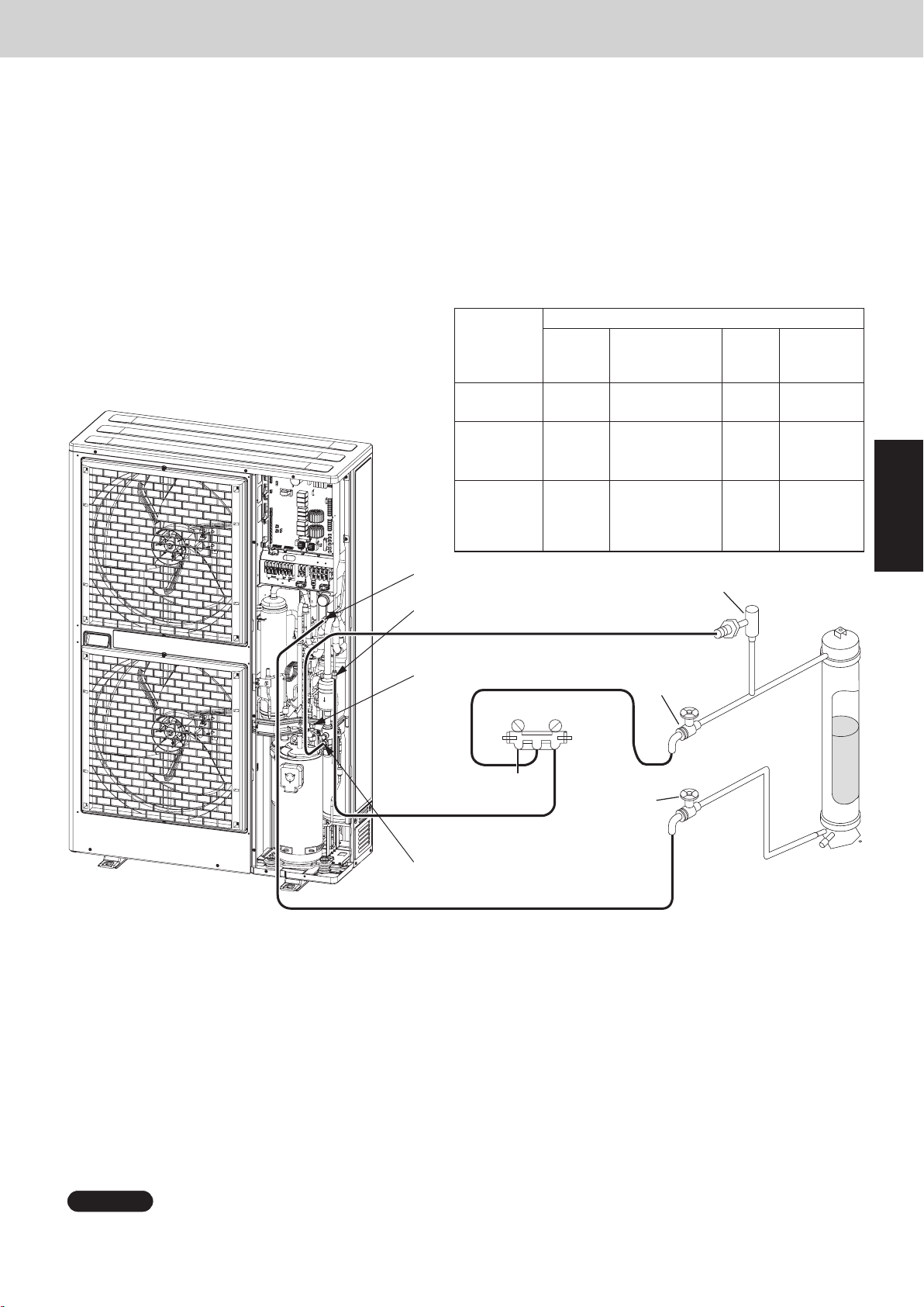
Mini VRF SYSTEM
2WAY SYSTEM
Outdoor Unit Repair Procedures
7. Charging Compressor Oil
6. Charging Compressor Oil
Next, follow the instructions in “3-2-1. Cooling operation (for all units)” at the outdoor unit where oil will be charged,
and start cooling operation at all units. After the operating conditions were stabilized, open each valve (Hi-side
manifold gauge, upper valve and lower valve) in sequence as follows.
(1) Open the valve on the high-pressure side of the manifold gauge.
(2) Open the upper valve.
(3) Open the lower valve.
When this is done, the refrigerant pressure from operation forces the oil out of the oil charge tank, and oil is charged
into the outdoor unit from the low-pressure outlet port. Occasionally close the upper valve on the top of the oil charge
tank (only this valve) and shake the tank to check the amount of remaining oil.
Process
Oil
charging
Oil charge
completed
Refrigerant
recovery
(oil-charging
tank inside)
Hi-side
manifold
gauge
Open
Close*
Close
Outdoor Unit Repair Procedures
Operating valve
Lo-side
manifold
gauge
Close
(No connection)
Close
(No connection)
Open
(Connect to
refrigerant
recovery tank)
Upper
valve
Open
Open
Open
Lower
valve
Open
Close after
approx. 60
seconds
Close
3
Low-pressure outlet port
(for ø7.94mm-dia connector)
High-pressure outlet port
(for ø7.94mm-dia connector)
Liquid tube service port
(for ø7.94mm-dia connector)
Manifold gauge
Lo Hi
Connect from here to
refrigerant recovery unit
Gas tube service port
(for ø7.94mm-dia connector)
(2)
Upper valve
(1)
(3)
Lower valve
DPR
Fig. 8
Completing oil-charging
To terminate the oil charging work, do as follows:
To end the charge process, first close the valve on the Hi-side manifold gauge. Then wait approximately 60
seconds in order to vaporize the refrigerant in the charge tank. Then fully close the lower valve.
Refrigerant recovery (oil-charging tank inside)
Finally, connect the refrigerant recovery unit to the Lo-side manifold gauge, shut down all indoor and outdoor units,
and then recover the remaining refrigerant in the oil-charging tank. Perform these procedures quickly and securely
so that no air can enter them. Then, charge the necessary amount of new refrigerant by referring to the “Installation
Instructions” that came with the outdoor unit.
NOTE
To determine the completion of refrigerant recovery, follow the instructions that came with the refrigerant recovery unit.
3 - 13
Page 72
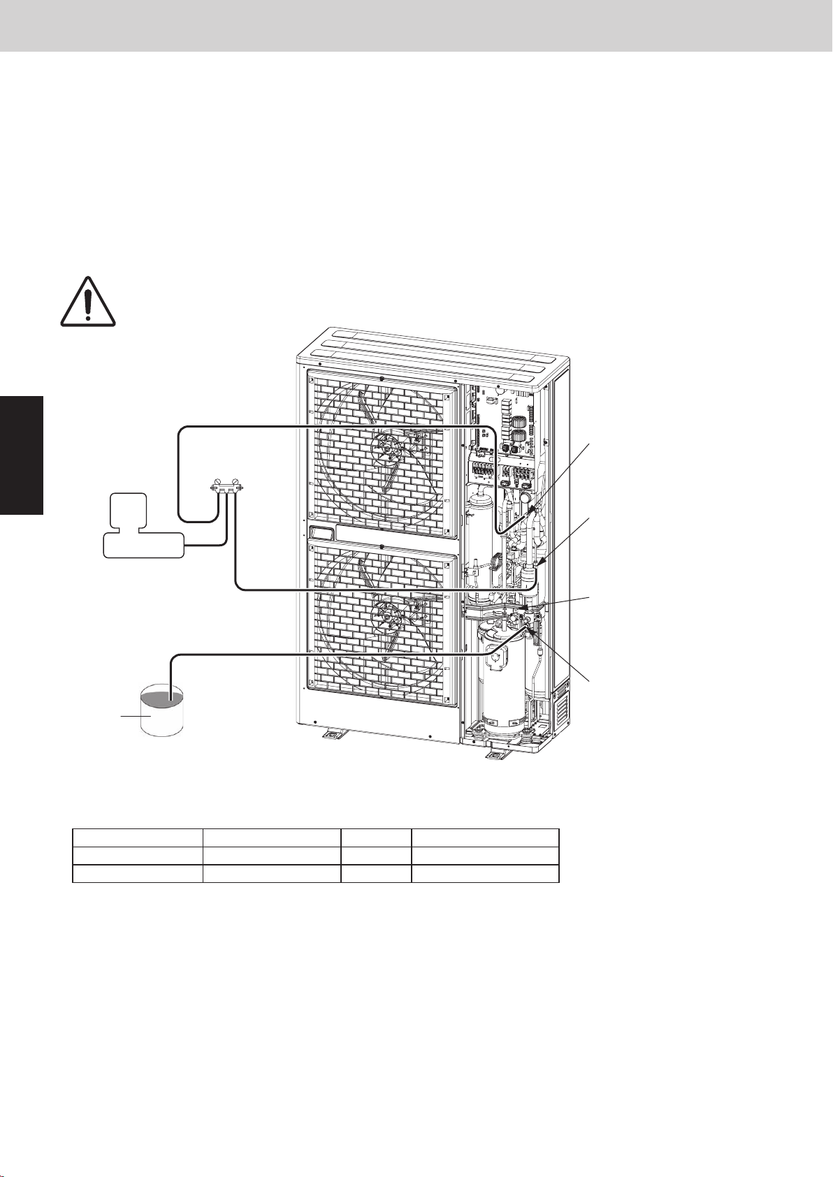
2WAY SYSTEM
Outdoor Unit Repair Procedures
7. Charging Compressor Oil
Mini VRF SYSTEM
6. Charging Compressor Oil
Outdoor Unit Repair Procedures
6-2. If Outdoor Unit Has Not Been Charged with Refrigerant
When a compressor has been replaced or in any other case where the outdoor unit has not been charged with
refrigerant, first charge with refrigerant then follow the instructions in “6-1. If Refrigerant Has Already Been Charged
to Outdoor Unit” and charge with oil.
Or, alternatively, follow the procedure below.
(1) Connect a tube to the oil outlet port on the outdoor unit to be charged with oil. Insert the other end of the tube into
the oil container.
(2) Follow the instructions in “5. Evacuating System,” and apply vacuum to the outdoor unit to be charged with oil.
When this is done, oil is charged into the outdoor unit through the oil outlet port.
(3) When the unit has been charged with the designated amount of oil, stop the vacuum pump.
3
CAUTION
Vacuum pump
Oil
The oil absorbs moisture readily. This work must be completed quickly.
Low-pressure outlet port
Manifold gauge
Lo Hi
(for ø7.94mm-dia connector)
High-pressure outlet port
(for ø7.94mm-dia connector)
Liquid tube service port
(for ø7.94mm-dia connector)
Gas tube service port
(for ø7.94mm-dia connector)
Fig. 9
6-3. Charging Additional Compressor Oil (after replacing compressor)
The rated amount of compressors as given below:
Rated Capacity Compressor model Q'ty Weight (OIL IN) [kg]
8HP
10HP
When replacing a faulty compressor, be sure to first measure the weight of the compressor.
If the surplus oil is removed along with the compressor, add the same amount of new oil.
For example:
Additional oil to be charged: 27.3 kg (removed compressor weight) – 27.1 kg (new compressor weight) = 0.2 kg ≒ 0.2 L
* If the result is a negative weight (removed compressor weight is less than the rated weight), it is not necessary
to discharge the extra oil from the system.
5JD650XDA22
5JD650XDA22
1
1
3 - 14
27.1
27.1
Page 73
Mini VRF SYSTEM
7.
Pumping Out Refrigerant from Outdoor Unit
For the method used for additional oil charging after compressor replacement, see the section “6-1. If Refrigerant
Has Already Been Charged to Outdoor Unit.”
Required equipment and tools: Jumper wire with clips, adjustable wrench, set of manifold gauge valves for the
refrigerant R410A, refrigerant recovery unit, pre-purged refrigerant cylinder for
recovery, flathead screwdriver, and outdoor unit maintenance remote controller.
This work is performed in order to collect the refrigerant from an outdoor unit where repairs (other than compressor
replacement) will be performed into other outdoor units and indoor units, and the refrigerant tubing.
7-1. If Remote Controller is Used for Maintenance of Outdoor Unit
(1) Connect the manifold gauge valves at the Lo side to the low-pressure outlet port of the outdoor unit.
Also connect the refrigerant recovery cylinder at the liquid tube service port (Schrader-type push-to-release
valve). Perform the connection work quickly so that no air is allowed to enter them. (Fig. 10)
* Connecting the refrigerant recovery cylinder is done to prevent pressure from rising excessively during backup
operation by recovering the refrigerant from the outdoor unit to be repaired.
(Measure the weight of the refrigerant and cylinder itself beforehand and provide sufficient safety measures,
such as installing a high-pressure cutout in the circuit.)
Outdoor Unit Repair Procedures
The hoses may be subject to internal pressure from the refrigerant inside the out-
CAUTION
(2) Connect the outdoor unit maintenance remote controller to the CN-RC connector (3P) (BLU) on the outdoor
unit control PCB. Then start a test run of all units. (Press and hold the
longer.)
(3) Use the outdoor unit maintenance remote controller to check the operating status of the indoor units. Check
that all units are operating in Heating mode. For details concerning operation of the outdoor unit maintenance
remote controller, see the section “Outdoor unit maintenance remote controller”. It is also possible to check the
operating conditions either in cooling or heating mode by touching the gas tube.
Cooling mode: low temperature (20℃ or lower)
Heating mode: high temperature (60℃ or higher)
CAUTION
(4) Then slowly close the liquid tube service valve.
(5) When the low pressure at the outdoor unit to be repaired reaches 0.5 MPa or below, press the ON/OFF button
on the outdoor unit maintenance remote controller to stop all the units. Then immediately fully close the gas
tube valve on that outdoor unit.
door unit. Check that the manifold gauge valves are fully closed beforehand. A
Schrader-type push-to-release valve is provided at each connection port.
(CHECK) button for 4 seconds or
The gas tubing becomes hot (60°C or higher) in heating. Be careful so as not to
be burnt when touching the tubing.
3
While closing the valves, the rise in discharge temperature or another factor may
CAUTION
(6) Connect the high-pressure gauge side of the manifold gauge to the high-pressure outlet port on the outdoor
unit, and connect the manifold gauge to the refrigerant recovery device. Be sure that no air enters the tubing at
this time.
cause a protective device to activate, stopping the operation of the outdoor unit. If this
occurs, immediately fully close the gas tube valve on the outdoor unit to be repaired.
3 - 15
Page 74
Mini VRF SYSTEM
7.
Pumping Out Refrigerant from Outdoor Unit
(7) Short-circuit the AP pin on the outdoor unit control PCB. Then turn ON the outdoor unit power.
When the AP pin is short-circuited and the power is turned ON, all solenoid valves
CAUTION
(8) Open both Hi- and Lo-side valves on the manifold gauge valves, and recover the refrigerant remaining in the
outdoor unit. Then measure the amount of recovered refrigerant.
NOTE
To determine the completion of refrigerant recovery, follow the instructions that came with the refrigerant recovery unit.
7-2. If Remote Controller is Not Available for Maintenance of Outdoor Unit
(1) Connect the manifold gauge valves at the Lo-side to the low-pressure outlet port of the outdoor unit.
Also connect the refrigerant recovery cylinder at the liquid tube service port (Schrader-type push-to-release
valve). Perform the connection work quickly so that no air is allowed to enter them. (Fig. 10)
* Connecting the refrigerant recovery cylinder is done to prevent pressure from rising excessively during the
3
operation by recovering the refrigerant from the outdoor unit to be repaired.
(Measure the weight of the refrigerant and cylinder itself beforehand and provide sufficient safety measures,
such as installing a high-pressure cutout in the circuit.)
in the outdoor unit are forced open, allowing the refrigerant to be recovered from all
tubes which are separated by solenoid valves. If this work is not performed, it will not
be possible to recover all of the refrigerant at the refrigerant recovery device. Be sure
to perform this step.
Outdoor Unit Repair Procedures
The hoses may be subject to internal pressure from the refrigerant inside the out-
CAUTION
(2) Short-circuit the MODE pin ("HEAT" side) on the outdoor unit control PCB.
(3) Short-circuit the CHK pin to start operation, leave the unit running for a while. Touch the gas tubing with fingers
to determine whether the unit is running in heating.
door unit. Check that the manifold gauge valves are fully closed beforehand.
A Schrader-type push-to-release valve is provided at each connection port.
3 - 16
Page 75
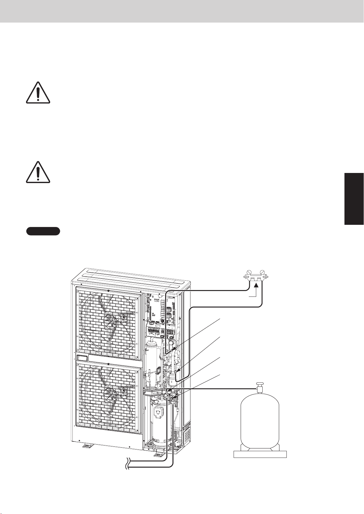
Mini VRF SYSTEM
7.
Pumping Out Refrigerant from Outdoor Unit
(4) Then slowly close the liquid tube service valve.
* When the low pressure at the outdoor unit to be repaired reaches 0.5 MPa or below, pull out the SCT connec-
tor from the outdoor unit control PCB of that outdoor unit. Then immediately fully close the gas tube valve on
that outdoor unit.
* Pulling out the SCT connector immediately stops all of the outdoor units.
While closing the valves, the rise in discharge temperature or another factor may
CAUTION
(5) Connect the high-pressure gauge side of the manifold gauge to the high-pressure outlet port on the outdoor
unit, and connect the manifold gauge to the refrigerant recovery device. Be sure that no air enters the tubing at
this time.
(6) Short-circuit the AP pin on the outdoor unit control PCB. Then turn ON the outdoor unit power.
cause a protective device to activate, stopping the operation of the outdoor unit. If this
occurs, immediately fully close the gas tube valve on the outdoor unit to be repaired.
Outdoor Unit Repair Procedures
CAUTION
(7) Open both Hi- and Lo-side valves on the manifold gauge valves, and recover the refrigerant remaining in the
outdoor unit. After that, measure the amount of recovered refrigerant.
NOTE
To determine the completion of refrigerant recovery, follow the instructions that came with the refrigerant recovery unit.
When the AP pin is short-circuited and the power is turned ON, all solenoid valves
in the outdoor unit are forced open, allowing the refrigerant to be recovered from all
tubes which are separated by solenoid valves. If this work is not performed, it will not
be possible to recover all of the refrigerant at the refrigerant recovery device. Be sure
to perform this step.
Manifold gauge
Lo Hi
Connect from here to
refrigerant recovery unit
Low-pressure outlet port
(for ø7.94mm-dia connector)
High-pressure outlet port
(for ø7.94mm-dia connector)
3
Indoor unit
Liquid tube service port
(for ø7.94mm-dia connector)
Gas tube service port
(for ø7.94mm-dia connector)
Refrigerant
recovery
cylinder
Measuring scale
Fig. 10
3 - 17
Page 76
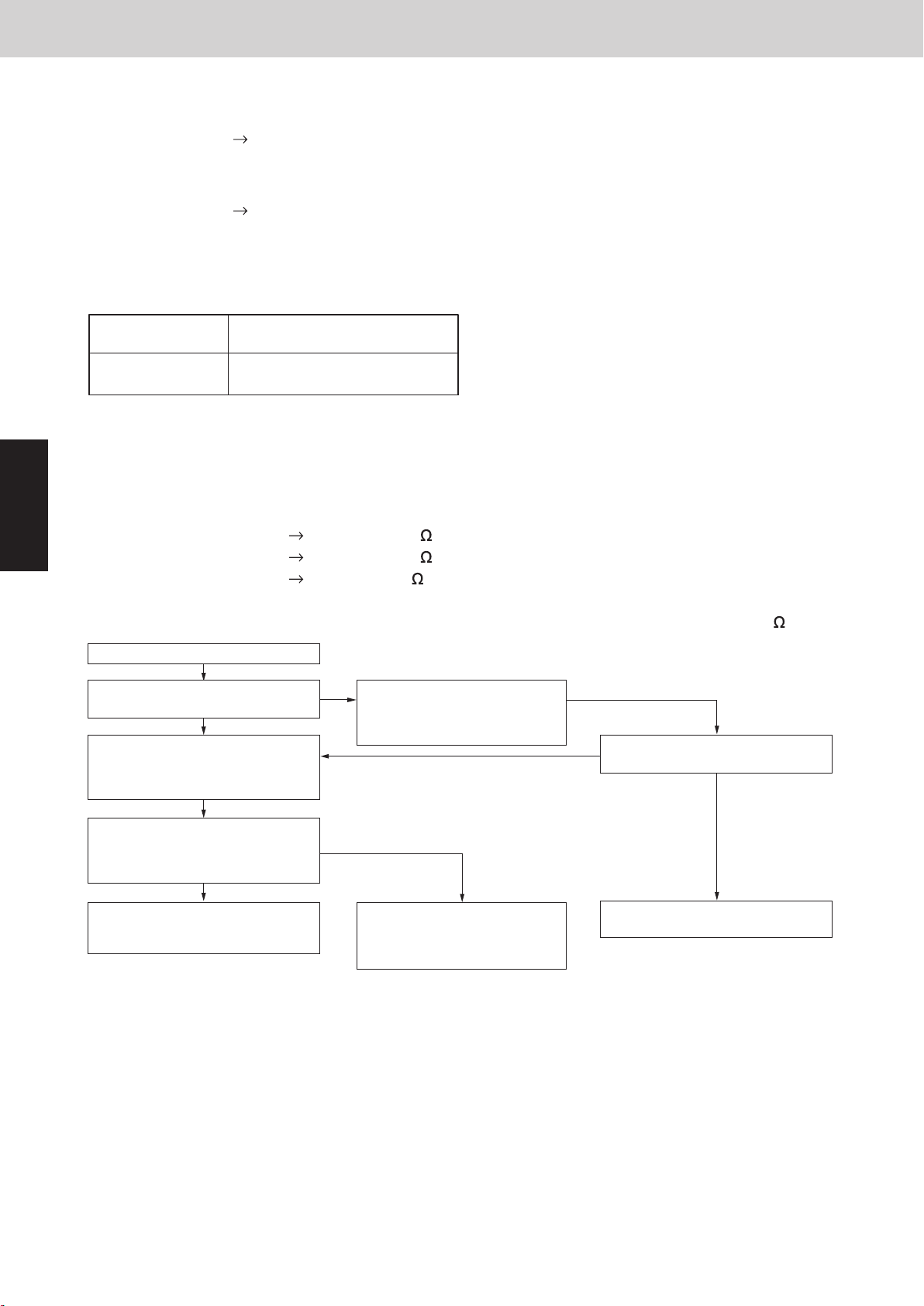
8. Compressor
8-1. Compressor Trouble Diagnosis and Check Methods
Generally, compressor failures can be classified into the following categories.
(1) Mechanical trouble (A) Locking (intrusion of foreign objects, galling, etc.)
(2) Electrical trouble (A) Coil burning
Trouble diagnosis is based on the following remote controller displays:
(B) Pressure rise failure (damaged valve, seal, bearing, or other component)
(C) Noise (damaged stator rotor, valve, or other component)
(B) Open circuit
(C) Insulation failure
(D) Short circuit
CompressorDisplay
Mini VRF SYSTEM
Outdoor Unit Repair Procedures
[H03]
Compressor 1
(INV compressor)
A judgment is made based on factors that include the following:
Coil resistance (varies depending on the compressor), insulation resistance, current, leakage breaker operation,
oil and refrigerant fouling, odor, pressure, and noise
Reference:
Insulation resistance (Use a DC 500 V insulation resistance meter and measure the insulation resistance
3
between the electrified and non-electrified parts.)
(a) Motor
Min. 300 M
(b) Compressor Min. 100 M (servicing part)
(c) Unit
Min. 10 M (This is due to the presence of refrigerant, which decreases
the insulation resistance.)
* Minimum insulation resistance as required by generally accepted requirements is 1 M
JUDGMENT START
Is there burning of the failed
compressor motor?
YES
Follow the instructions in
“2. Discharging Compressor Oil” and
drain the oil from all compressors in the
same system. Then inspect.
NO
Follow the instructions in
“2. Discharging Compressor Oil”
and drain the oil from the failed
compressor. Then inspect.
Is the color phase 4.0 or above, or is a
YES
sharp odor present?
.
NO
Are there 2 or more outdoor units where
the compressor oil color phase is 4.0 or
higher or where a sharp odor is
present?
YES
Follow the instructions in “8-2-2. Dry
core cleaning” and perform dry core
cleaning of all outdoor units.
NO
Follow the instructions in
“8-2-2. Dry core cleaning” and
perform dry core cleaning of the
failed outdoor unit.
Reference: Symptoms of motor burning
1. Ground fault results in breaker operation.
2. Short circuit results in different coil resistance at different phases.
3. Open circuit
3 - 18
Go to “8-2-1. Replacing only the
failed compressor.”
Page 77

Mini VRF SYSTEM
8. Compressor
8-2. Replacing the Compressor(s)
8-2-1. Replacing compressor
(1) Follow the instructions in “8-3. Removing Compressor” and replace the failed compressor.
(2) Fully close the high- and low-pressure gauge valves on the manifold gauge, then stop the vacuum pump.
(3) Disconnect the manifold gauge from vacuum pump. Connect the manifold gauge to the cylinder where the
refrigerant was recovered. At this time, be careful that air does not enter the tubing.
(4) Open the valve on the refrigerant recovery cylinder and the high-pressure gauge valve on the manifold gauge to
charge with refrigerant. At this time, the low-pressure gauge valve on the manifold gauge remains fully closed.
If the recovered refrigerant becomes mixed with another refrigerant or another gas
CAUTION
(5) When charging has been completed with an amount of new refrigerant equal to the amount of recovered
refrigerant, or when charging with the same amount of new refrigerant has not been completed but no more
refrigerant will enter the unit, fully close the high-pressure gauge valve on the manifold gauge. Next, turn
the power OFF at the repaired outdoor unit, then remove the short circuit at the AP pin. Finally, fully open all
valves on the gas tube and liquid tube.
(6) If charging with an amount of new refrigerant equal to the amount of recovered refrigerant was not possible,
fully close the high-pressure gauge valve on the manifold gauge. Then, while the unit is operating in “3-2-1.
Cooling operation (for all units)”, open the low-pressure gauge valve on the manifold gauge and charge with
the designated amount of refrigerant.
(such as nitrogen or air), do not use the recovered refrigerant for charging. Charge
with the designated amount of new refrigerant.
Outdoor Unit Repair Procedures
3
CAUTION
(7) If necessary, follow the instructions in “6. Charging Compressor Oil,” and charge with oil.
(8) Remove the manifold gauge.
CAUTION
When charging with liquid refrigerant, add refrigerant a little at a time in order to
prevent liquid back-flow.
The connecting port employs a Schrader-type push-to-release valve. When disconnecting the hose, pressure will be applied from the refrigerant in the outdoor unit.
3 - 19
Page 78
Mini VRF SYSTEM
8. Compressor
8-2-2. Dry core cleaning
If burning or other failures occur repeatedly at compressors, in many cases the cause is acid, sludge, carbon,
or other substances that remain in the refrigeration cycle as the result of insufficient cleaning. If, when the oil is
inspected, there is an outdoor unit where the oil color phase is 4.0 or higher, or where a sharp odor is present,
carry out all steps below to perform dry core cleaning.
And use the bidirectional dry core for refrigerant R410A.
(A) If a ball valve is installed on the outdoor unit
(1) All units are operated in either Cooling or Heating mode.
For Cooling operation, see the Section 3-2-1. For Heating operation, see the Section 7-1 and 7-2.
(2) If all units are operated in Cooling mode, close the liquid tube service valve then the ball valve.
If all units are operated in Heating mode, close the ball valve then the liquid tube service valve.
* This step is performed in order to expel refrigerant from the tubing between the liquid tube service valve and
the ball valve. Approximately 4 – 5 seconds is a sufficient interval between closing each of the 2 valves.
(3) Press the ON/OFF button on the outdoor unit maintenance remote controller to stop the operation of all units.
* If the outdoor unit maintenance remote controller is not available, use the following method to stop the oper-
ation of all units:
Pull out the SCT connector from the outdoor unit control PCB. When the SCT connector is pulled out, alarm
F12 (sensor trouble) immediately occurs and all outdoor units stop operating. Be sure that you do NOT grasp
the lead wire when pulling out the connector. Removing any other connector may not cause the units to stop.
3
Therefore be sure to pull out only the SCT connector.
(4) Connect a refrigerant recovery device to the liquid tube service port (Schrader-type valve) of outdoor unit
where dry cores will be attached, then recover the refrigerant from the tubing. Be sure that no air enters the
tubing at this time.
Outdoor Unit Repair Procedures
When the hose is connected, internal pressure is applied by the remaining refrigerant
CAUTION
(5) As shown in Fig. 11, disconnect the tube that runs from the liquid tube valve to the ball valve on outdoor unit
where dry cores will be attached. Then attach the dry cores.
(6) At outdoor unit where dry cores are attached, pressurize with 3.8 MPa of nitrogen from the liquid tube service
port and check for leaks.
(7) After evacuating all nitrogen gas from the tubing, apply vacuum from the liquid tube service port to outdoor
unit where dry cores are attached until the pressure is –101kPa {–755 mm Hg, 5 Torr} or less.
(8) Fully open the liquid tube valve and ball valve on all outdoor units where dry cores are attached.
(9) Operate all units for approximately 3 hours (in either Heating or Cooling mode).
(10) Follow the above procedure, and replace dry cores with new dry cores.
(11) Operate all units for approximately 20 minutes (in either Heating or Cooling mode).
(12)
Follow the instructions in “2. Discharging Compressor Oil” and drain a small amount of the oil from the oil separators
of outdoor unit where dry cores are attached. Check the color phase, odor, and other characteristics.
(13) If the results show that dry core cleaning is still necessary (for example, a color phase of 4.0 or higher)*, return
to Step 11 and repeat until the results return to normal (including a color phase of 3.5 or less)*.
* Color sample sheet for degree of stain
CAUTION
in the inter-unit tubing. The connection port employs a Schrader-type valve. To
determine when refrigerant recovery is complete, follow the instructions in the
instruction manual of the refrigerant recovery device.
Perform another dry core replacement after approximately 30 hours of system operation.
(14) Perform steps (1) – (4), and remove all dry cores. Then connect the tubing between the liquid tube valves and
the ball valves.
(15)
At outdoor unit where dry cores were removed, pressurize with 3.8 MPa of nitrogen from the liquid tube service port
and check for leaks.
3 - 20
Page 79
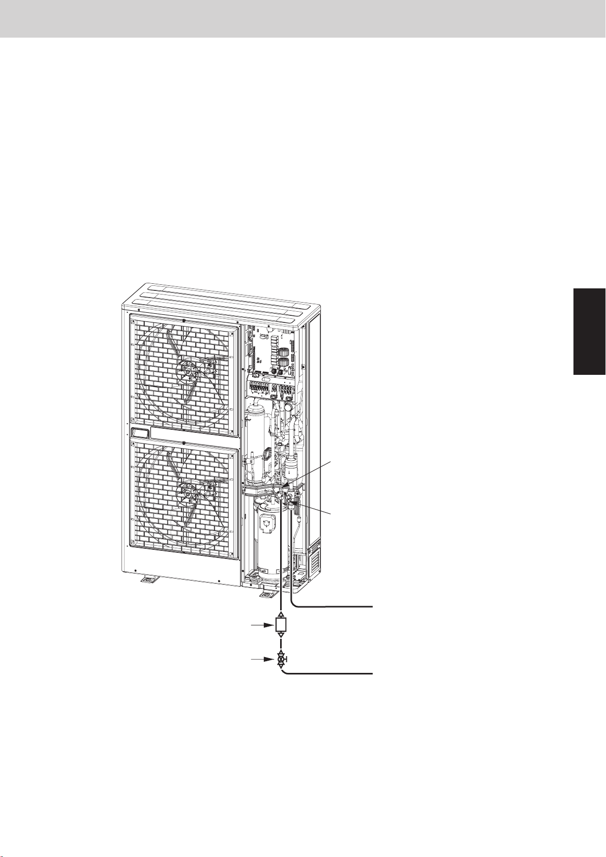
Mini VRF SYSTEM
8. Compressor
(16) After evacuating all nitrogen gas from the tubing, apply vacuum to outdoor unit where dry cores were removed
until the pressure is –101kPa {–755 mm Hg, 5 Torr} or less.
(17) Refer to the Installation Instructions for further information. Charge with an amount of refrigerant equal to the
amount that was recovered.
(B) If a ball valve is not installed on the outdoor unit
(1) See the section “3-2-3. Refrigerant recovery procedures (2) : Indoor unit with no ball valve equipped”. Perform
pump down of the refrigerant from all indoor units and inter-unit tubing to the outdoor unit side.
(2) Cut the liquid tube at all outdoor units where dry cores will be attached, then attach the dry cores and ball
valves as shown in Fig. 11.
(3) For the next steps, see the steps (6) – (17) in
Cleaning dry core
on the previous page.
(A)
Outdoor Unit Repair Procedures
Dry core (bidirectional:
for R410A refrigerant)
Liquid tube service port
(for ø7.94mm-dia connector)
Gas tube service port
(for ø7.94mm-dia connector)
Gas tube
Indoor unit
3
Ball valve
Fig. 11
3 - 21
Liquid tube
Indoor unit
Page 80

Mini VRF SYSTEM
2WAY SYSTEM
Outdoor Unit Repair Procedures
9. Compressor
8. Compressor
Outdoor Unit Repair Procedures
8-3. Removing Compressors
Use caution to prevent water or foreign particles from invading the refrigerant tube while removing and installing
the compressor.
8-3-1. Removing Compressors
(1)
After recovering refrigerant in the system, replace the nitrogen gas through the service valve port.
(2)
Remove the insulator containing the compressor and heat insulating material surrounding the oil balance tube.
(3)
Remove the compressor terminal cap and then take out the supply terminal.
(4)
Remove the crankcase heater.
(5)
Remove the hexagonal nuts with washer from three locations.
(6)
Cut out the tube on the compressor side because the suction tube showing in the figure is rigid and unmovable.
(7)
Remove each welded part on the discharge side (one location) and on the oil balance tube (one location) showing
in the figure.
3
(8)
(9)
NOTE
Protect the sensor part, sheet-metal area, lubber, lead wire, clamper, etc.
Pull the compressor toward you.
Remove the welded part on the suction side of the cut-out tube of the compressor side attached to the suction tube.
Suction tube
Suction side welded part
Tube of compressor side
Discharge side welded part
(one location)
Compressor
Oil balance tube welded part
(one location)
3 - 22
Page 81

Mini VRF SYSTEM
Contents
Outdoor Unit Maintenance Remote Controller
4. OUTDOOR UNIT MAINTENANCE REMOTE CONTROLLER
1. Overview .............................................................. 4-2
2. Functions ............................................................. 4-3
3. Ordinary Display Controls and Functions .................................. 4-4
4. Monitoring Operations .................................................. 4-9
5. Outdoor Unit Alarm History Monitor ...................................... 4-11
6. Mode Settings ........................................................ 4-12
4
4 - 1
Page 82

1. Overview
Mini VRF SYSTEM
Outdoor Unit Maintenance Remote Controller
OUTDOOR UNIT MAINTENANCE REMOTE
CONTROLLER (CZ-RTC4) for 2WAY VRF
n
About the outdoor unit maintenance remote controller
The outdoor unit utilizes nonvolatile memory (EEPROM) on
its PCB. This allows EEPROM data to replace the setting
switches that were present on previous PCBs. The outdoor
unit maintenance remote controller is used to set and change
these EEPROM data.
In addition to setting and checking the outdoor unit EEPROM
data, this remote controller can also be used to monitor the
outdoor unit alarm history, monitor the various indoor and
outdoor temperatures, and check the indoor unit connection
status (number of units, operating mode, etc.).
NOTE
Outdoor unit maintenance remote controller does not function as an
ordinary remote controller. It is therefore only used for test runs and
during servicing.
System diagram
Outdoor unit maintenance
remote controller
Special service checker wiring
(Servicing No.: CV6231785082)
Outdoor unit
[Service Checker Section]
A
CZ-RTC4
Inter-unit control wiring
4
Interface for
outdoor unit
maintenance
A
Operation manual included in package.
l
The special service checker wiring is required in order to connect the outdoor unit maintenance remote controller
Remote controller Ass’y
remote controller
(Servicing No.:
CV6231616171)
Outdoor unit
control PCB
Indoor
unit
Remote
controller
Indoor
unit
Remote
controller
to the outdoor unit PCB.
l
Ordinary remote controllers or other controller are still required for the indoor units, even when the outdoor unit
maintenance remote controller is connected.
4 - 2
Page 83

Mini VRF SYSTEM
2. Functions
n
Functions on the ordinary display
(1) Functions: Button operations can be used to perform the following functions.
• Start/stop of all indoor units
• Switching between cooling and heating
• Test run of all indoor units
• Double-speed operation of indoor units (Do not use for actual operation. Doing so may damage the devices.)
(2) Display: The following can be displayed.
• Alarm details display
• No. of indoor/outdoor units
• Unit Nos. of connected indoor/outdoor units
• Indoor/outdoor unit operating status (blinks when an alarm occurs)
• Indoor unit thermostat ON
• Display of individual outdoor unit alarms
• Total operating time of outdoor unit compressors
• Oil level of the outdoor unit oil sensor
• Total outdoor unit power ON time
• Outdoor unit microcomputer version, other information
Outdoor Unit Maintenance Remote Controller
n
Temperature monitor
• Displays the indoor/outdoor unit sensor temperatures.
n
Outdoor unit alarm history monitor
• Displays the outdoor unit alarm history.
n
Mode settings
• Setting mode 1 and setting mode 2 are used to make the outdoor EEPROM setting.
4
4 - 3
Page 84

3. Ordinary Display Controls and Functions
n
Functions on the ordinary display
•
Connect the special service checker wiring to the outdoor unit PCB.
The connection is shown in the figure below.
Mini VRF SYSTEM
Outdoor Unit Maintenance Remote Controller
4
When connecting the special service
checker wiring to the remote controller
CZ-RTC4, cut out the wire as shown in the
figure below because the connector of the
remote controller cannot be used directly.
Top case
(Back side)
CZ-RTC4
(2P, WHT)
l
If the communications line in the inter-unit control wiring is connected, it can be left as-is.
l
In case of an independent outdoor unit (1 maintenance remote controller connected to 1 outdoor unit, auto
Special service
checker wiring
CUT
Terminal board
6 mm
Remove the coating.
Approx. 6 mm
Relay connector
(2P, WHT)
PCB connector
(3P, BLU)
Bottom case
(Back side)
RC
(3P, BLU)
Outdoor unit PCB
address setting for indoor units not completed), both setting mode 1 and setting mode 2 can be used.
l
The overall system status for that refrigerant system is displayed.
4 - 4
Page 85
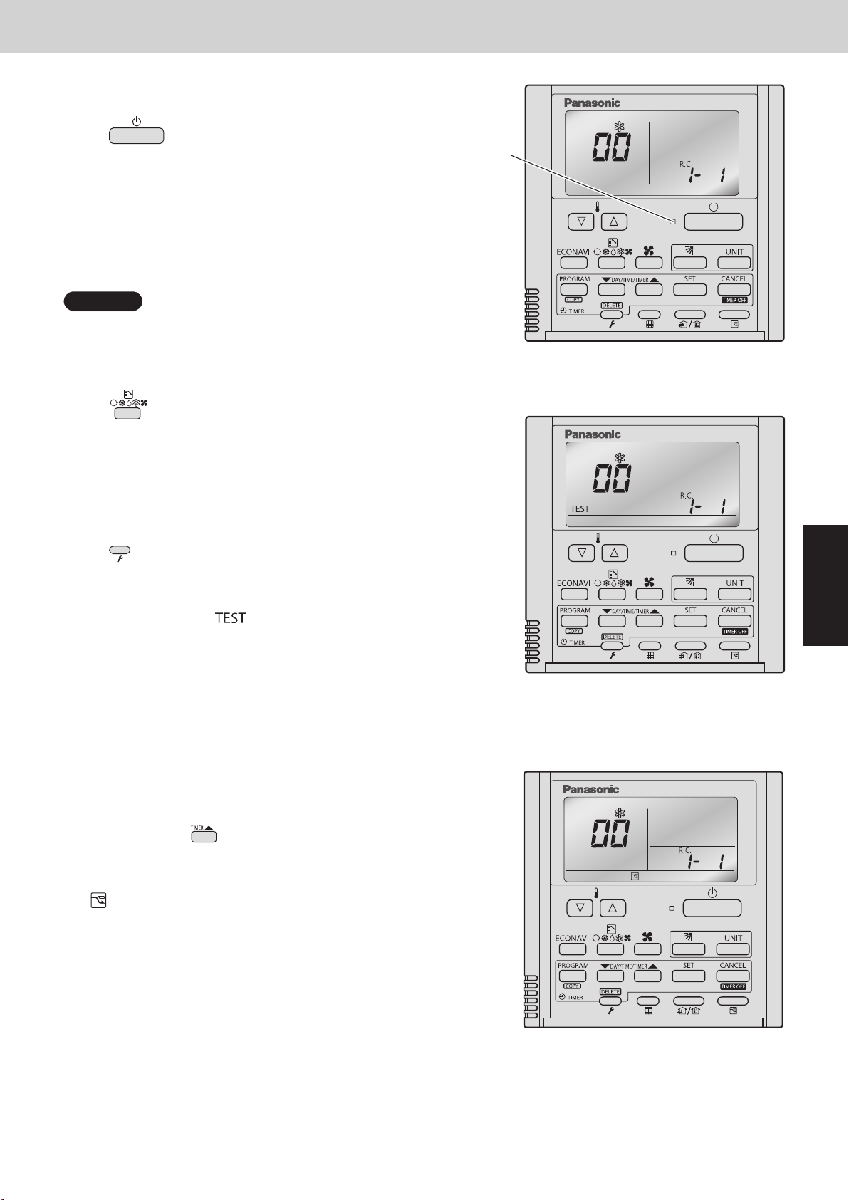
3. Ordinary Display Controls and Functions
l
All units start/stop
<Operation>
The (Start/Stop operation) button can be used
to start and stop all the indoor units.
• The LED illuminates if any indoor units is operating.
• The LED blinks if an alarm at any of the operating indoor
units occurs.
l
Cooling/heating change
NOTE
Cooling and heating mode changes are only available
when all indoor units are stopped.
<Operation>
The
A
(Mode) button can be used to change
between heating and cooling operation.
Mini VRF SYSTEM
Outdoor Unit Maintenance Remote Controller
LED
A
• The display indicates the operating mode of the indoor
unit with the lowest unit No.
l
All units test run
<Operation>
The (Check) button can be used to start and stop a
test run for all indoor units.
• Press and hold for 4 seconds to turn ON.
During the test run “
” is displayed.
• The status of test runs performed from the indoor unit
remote controller is not displayed on the outdoor unit
maintenance remote controller.
l
Double-speed
• Do not use for actual operation.
(Doing so may damage the devices.)
<Operation>
The timer button
can be used to change between
double-speed and normal operation.
A
4
• During double-speed operation, the Sleeping Mode
mark is displayed.
A
4 - 5
Page 86
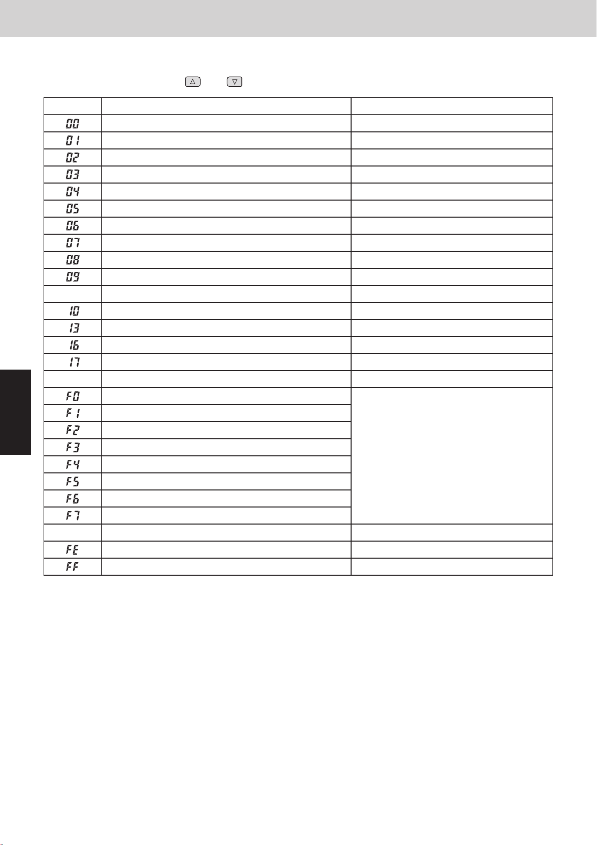
3. Ordinary Display Controls and Functions
n
Display (functions)
Use the temperature setting and buttons to change the item code.
•
Outdoor Unit Maintenance Remote Controller
Mini VRF SYSTEM
Item code
À
Item Remarks
Á
Outdoor unit alarm Alarm code display
No. of connected indoor units Quantity
Unit Nos. of connected indoor unit 7-segment display
Operating status of indoor unit 7-segment display
Thermostat ON status of indoor unit 7-segment display
No. of connected outdoor units 1 – 4
Unit Nos. of connected outdoor units 7-segment display
Operating status of outdoor unit compressor 7-segment display
Compressor 1 operating time 0 – 99999999 hours
Compressor 1 oil level 0 = Empty 1 = Insufcient 2 = Sufcient
Outdoor unit power ON time 0 – 99999999 hours
Compressor 1 operation count 0 – 65535 times
Alarm history 1 (most recent)
4
Alarm history 2
Alarm history 3
Alarm history 4
Alarm history 5
Alarm history 6
Alarm history 7
Alarm history 8 (oldest)
Firmware version Display the version No. × 100.
Program version Display the version No. × 100.
and Á correspond to Fig. 1 on the next page.
À
Display only. Alarm code and unit No. of unit
where alarm occurred are displayed alternately.
0 = CCU
1 – 4 = Outdoor unit
4 - 6
Page 87

3. Ordinary Display Controls and Functions
XX-YY R.C.
Â
Displays the outdoor unit sub-bus address which is
currently selected.
XX = Outdoor system address on main bus line (1 – 30)
YY = Outdoor unit sub-bus address (1 – 8)
“1” appears when there is only 1 outdoor unit.
Mini VRF SYSTEM
Outdoor Unit Maintenance Remote Controller
Locations where
shown in Fig. 1.
1
A
, and  are displayed as
À, Á
2
3
<Sample displays>
A
01: <No. of connected indoor units>
4 units connected
LED
Fig. 1
4
A
02: <Unit Nos. 1, 2, 3 and 4 are
connected>
4 - 7
Page 88
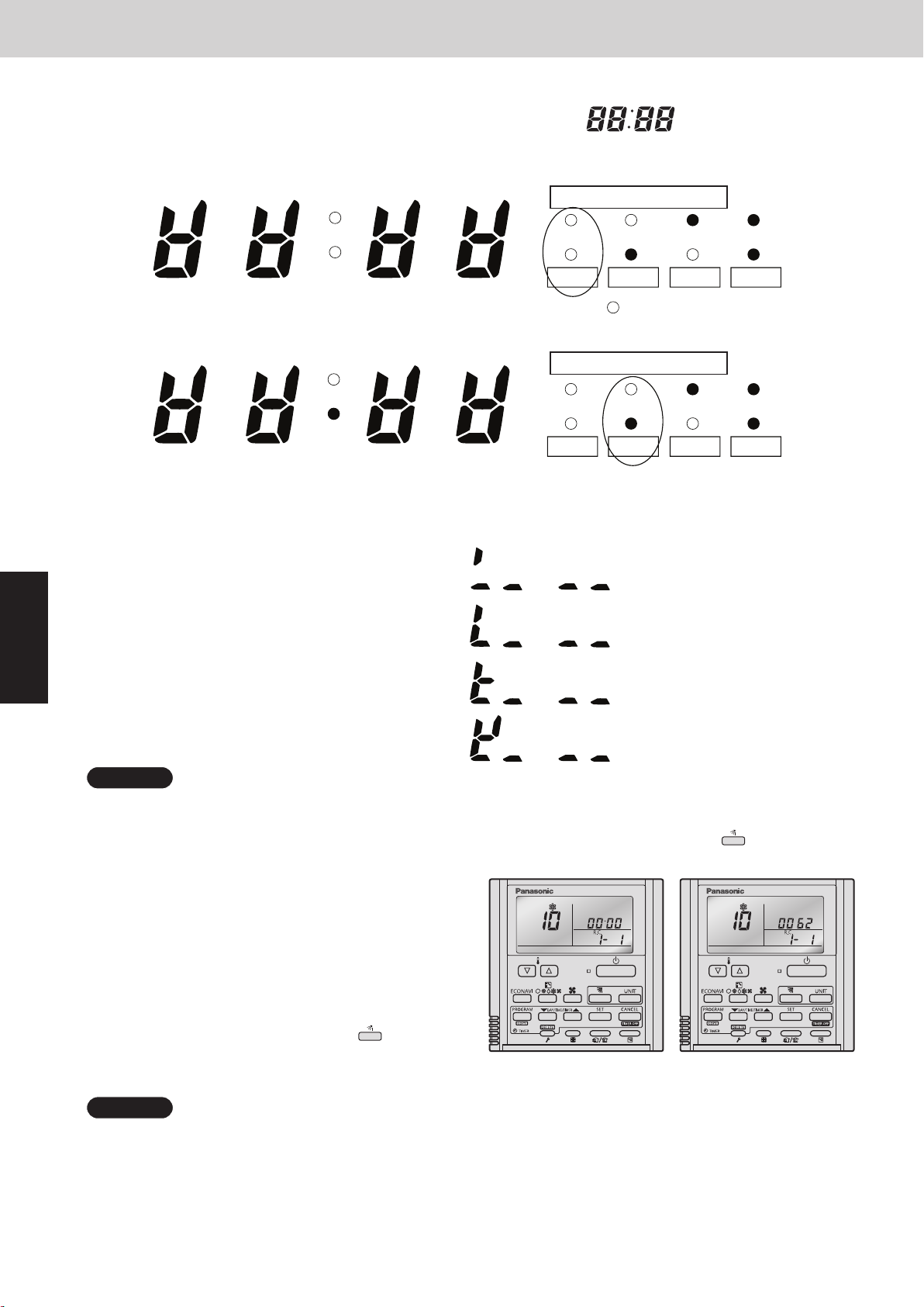
3. Ordinary Display Controls and Functions
n
Concerning the 7-segment, 4-digit display remote controller timer display
Outdoor Unit Maintenance Remote Controller
The unit Nos. of connected units are indicated by four 7-segment digits (
l
Display of unit Nos. 1 − 20
Mini VRF SYSTEM
) and a colon.
4
OFF OFF OFF OFF
1
3 13 188
2 7 12 17
5 10 15 20
6 11 16
4 14 199
Meaning of display colon
1 ~ 20 21 ~ 40 41 ~ 60 61 ~ 80
ON ON ON ON
is not displayed.
l
Display of unit Nos. 21 − 40
OFF OFF OFF OFF
21
23 33 3828
22 27 32 37
26 31 36
24 34 3929
25 30 35 40
Meaning of display colon
1 ~ 20
21 ~ 40
ON ON ON ON
l
The meaning of the colon changes in the same way to indicate unit Nos. up to 80.
l
Sample displays of the connected indoor unit Nos.:
•
Display of unit No. 1
•
Display of unit Nos. 1 and 2
41 ~ 60 61 ~ 80
•
Display of unit Nos. 1, 2, and 3
•
Display of unit Nos. 1, 2, 3, and 4
NOTE
The change of the colon display (between unit Nos. 1-20 to unit Nos. 21-40) occurs automatically
every 10 seconds. (However the display does not change if there are no higher-number units connected.)
To change the display to the higher-number units before 10 seconds have passed, press the (Flap) button.
n
The total compressor operating time is displayed
(B)(A)
(in 1-hour units) using 8 digits.
• When the rst 4 digits are displayed, the top
dot of the colon is illuminated. (Figure (A))
• When the last 4 digits are displayed, the colon
dot is OFF. (Figure (B))
• The display of the rst 4 digits and last 4 digits
AA
changes automatically after 10 seconds. The display
can also be changed by pressing the
button.
(Flap)
10: <Compressor’s total operating time>
(A) and (B) are displayed alternately.
(The example here (0000, 0062) indicates 62 hours.)
NOTE
With the outdoor unit maintenance remote controller (when connected to the outdoor unit), the unit remote
controller check functions will not operate.
4 - 8
Page 89
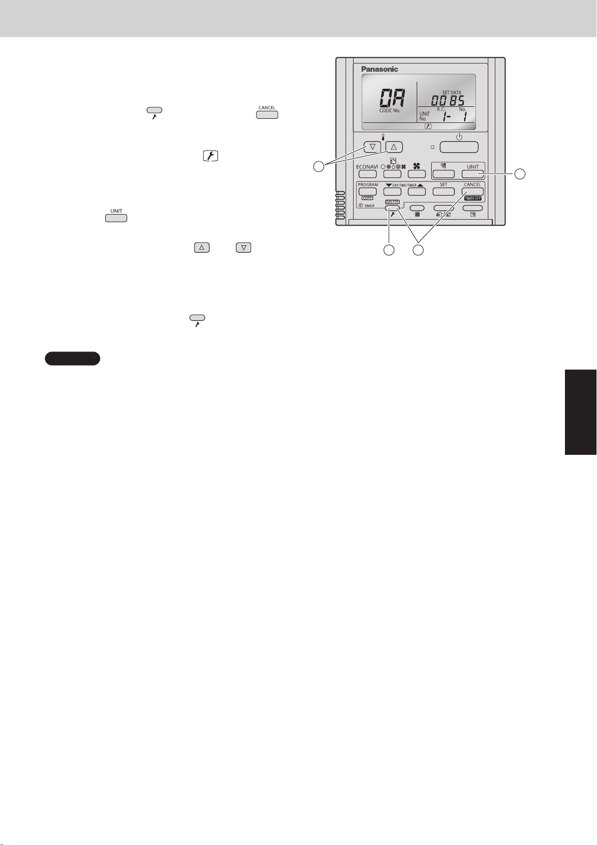
4. Monitoring Operations
Display the indoor unit and outdoor unit sensor
temperatures.
<Operating procedure>
Press and hold the (Check) button and
À
buttons simultaneously for 4 seconds or longer to
engage temperature monitor mode.
Mini VRF SYSTEM
Outdoor Unit Maintenance Remote Controller
During temperature monitoring,
(The display and operations are the same as
for monitor mode using the indoor unit remote
controller.)
Press the button and select the indoor unit to
Á
monitor.
Press the temperature setting and buttons
Â
and select the item code of the temperature to
monitor.
The unit No. of the selected indoor unit, and the
temperature data, are displayed.
To end monitoring, press the (Check) button.
Ã
The display returns to the normal display.
NOTE
The display does not blink.
is illuminates.
3
A
4
1
2
4
4 - 9
Page 90
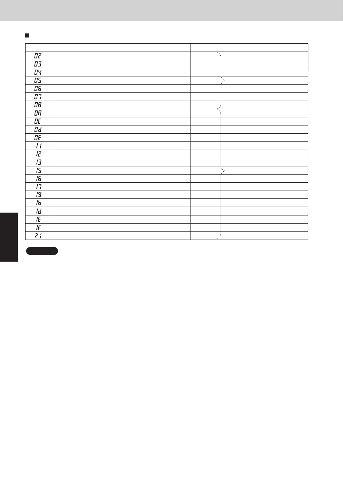
4. Monitoring Operations
Display of unit No. 1 (main unit)
Indoor unit intake temp. (TA)
Indoor unit heat exchanger temp. E1 (E1)
—
Indoor unit heat exchanger temp. E3 (E3) Indoor unit
Discharge air temp. (BL)
Discharge air temp. setting
Indoor unit MOV pulse (MOV) STEP
Discharge temp. (DISCH)
High-pressure sensor temp.
Heat exchanger gas (EXG)
Heat exchanger liquid (EXL)
Outdoor air temp. (TO)
Inverter secondary current
Inverter primary current (L2 phase)
—
Inverter actual operating frequency
Inverter primary current (L1 phase)
Low-pressure sensor temp.
Suction temp. (SCT)
Detected oil temp. (OIL)
4
Inverter primary current (L3 phase)
Mini VRF SYSTEM
Outdoor Unit Maintenance Remote Controller
RemarksDescriptionDN
°C
°C
°C
°C
°C
°C
°C
°C
°C
°C
A
A
STEPMOV pulse 1 (MOV1)
STEPMOV pulse 2 (MOV2)
Hz
A
°C
°C
°C
A
Outdoor unit
NOTE
0A and subsequent items are outdoor unit data.
It takes about 10-second long until outdoor unit data appears or changes on the display.
4 - 10
Page 91
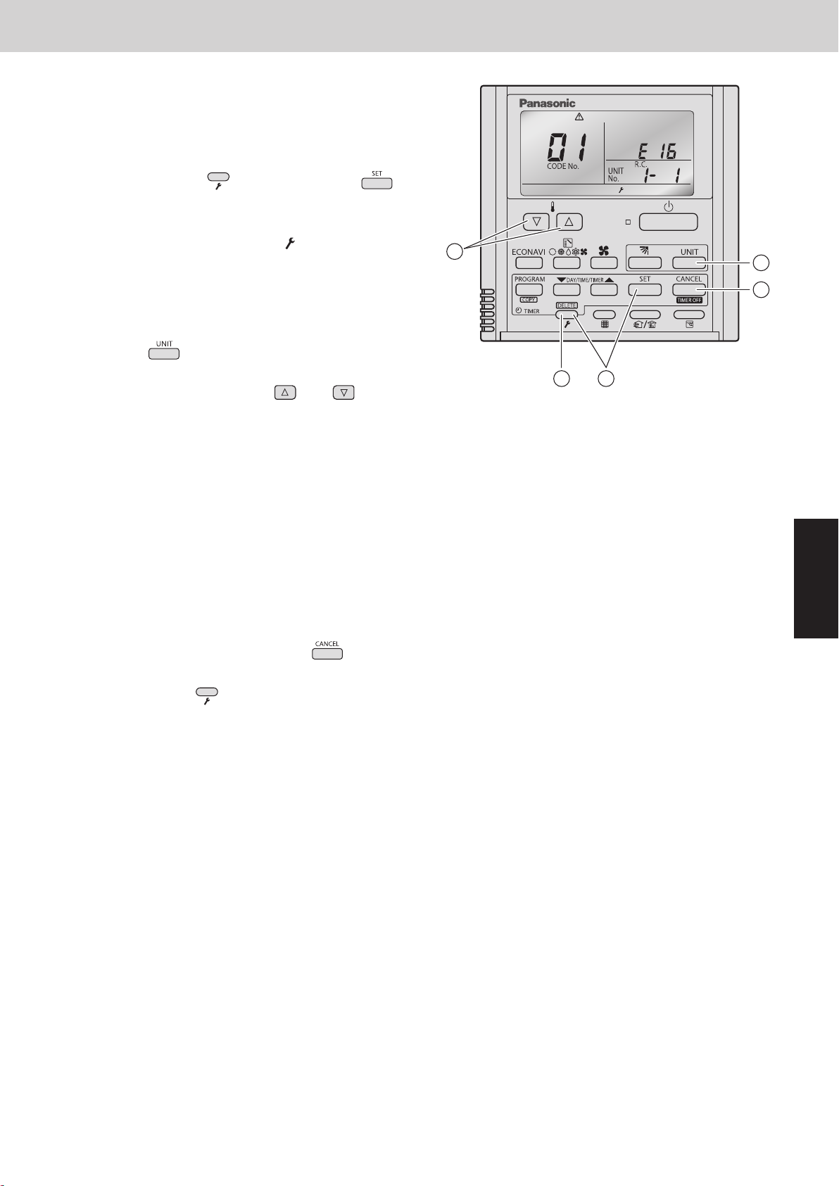
5. Outdoor Unit Alarm History Monitor
•
Displays outdoor unit alarms only.
•
Check the indoor unit alarm histories separately using the
indoor unit remote controllers or other control device.
<Operating procedure>
Mini VRF SYSTEM
Outdoor Unit Maintenance Remote Controller
Press and hold the (Check) button and
À
button simultaneously for 4 seconds or longer to engage
outdoor unit alarm history mode.
During temperature monitoring,
The display and operations are the same as for the
alarm history monitor performed from the indoor unit
remote controller. However the “UNIT No.” display shows
the outdoor unit address.
Press the button and select the outdoor unit for
Á
which to monitor the alarm history.
Press the temperature setting and buttons and
Â
select the item code for the alarm history.
The select outdoor unit address, the item code, and the
alarm history (alarm data) are displayed.
The outdoor unit address is displayed as R.C. XX-YY.
System XX = Outdoor unit system address
R.C. XX = Outdoor unit system address
YY = Outdoor unit sub-bus address
Item codes 01-08 are displayed. 01 indicates the most
recent alarm.
illuminates.
3
A
2
4
5
1
4
The alarm history displays the alarm code. (If no alarm
are present, then -- -- is displayed.)
To clear the alarm history, press the button. (The
Ã
outdoor unit alarm history will be cleared.)
To exit, press the (Check) button. The display
Ä
returns to the normal display.
4 - 11
Page 92
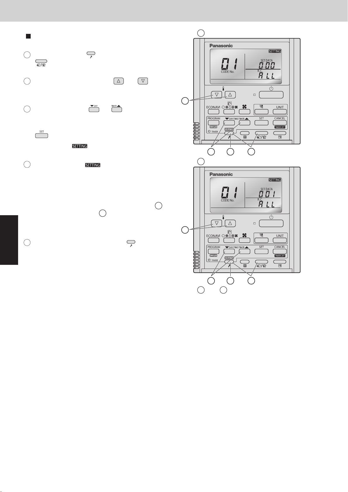
2WAY SYSTEM
Outdoor Unit Maintenance Remote Controller
6. Mode Settings
6. Mode Settings
Setting mode 1
<Operating procedure>
Mini VRF SYSTEM
Outdoor Unit Maintenance Remote Controller
Display of fi rst 3 digits
A
4
Press and hold the 1
(Ventilation) button simultaneously for 4
seconds or longer.
2
Press the temperature setting and
buttons to change the item code. The item codes
and setting data are shown in the table below.
Press the timer time buttons to
3
change the setting data.
To confirm the changed setting data, press the
button.
(At this time, “ ” display stops blinking
and remains lit.)
4
During this mode, “ ” is displayed,
blinking. The outdoor unit address display section
displays “ALL,” the item code and number (DN
value in the table), and the setting data (6 digits).
(The setting data is displayed in 6 digits. The
display changes between the first 3 digits (Fig.
and the last 3 digits (Fig.
When the first 3 digits are displayed, the bottom dot
of the colon is illuminated.)
To exit the setting mode, press the (Check)
5
button.
(Check) button and
and
).
B
2
B
A
)
2
A
3
Display of last 3 digits
5
A
1
3
A
and are displayed alternately.
(Example shows display of 000 001.)
Regarding the parameter setting, see the item "11. Detailed Settings in EEPROM of Outdoor Unit" under
the Section 1.
5
B
1
4 - 12
Page 93

Mini VRF SYSTEM
Contents
Remote Controller Functions
5. REMOTE CONTROLLER FUNCTIONS
1. Simple Settings Function ................................................ 5-2
2. Detailed Settings Function ............................................... 5-8
3. Remote Controller Servicing Functions ................................... 5-21
5
5 - 1
Page 94
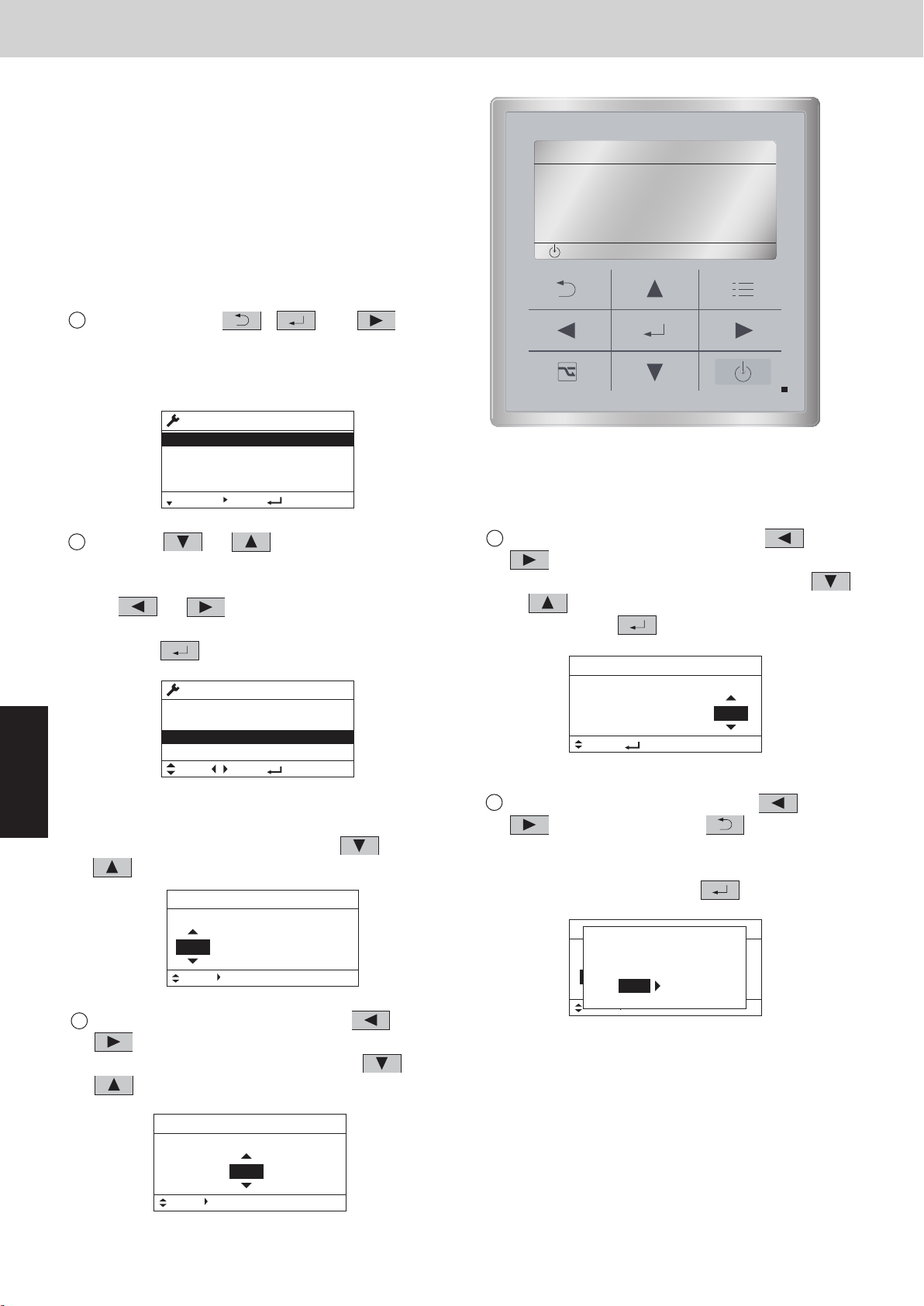
1. Simple Settings Function
1
Press and hold the and buttons
simultaneously for 4 seconds or longer.
2
“ ”, unit No.“ ” (or “” in the case
of group control), item code “ ”, and settings
data “” are displayed blinking on the remote
controller LCD display. At this time, the indoor unit
fan (or all indoor unit fans in the case of group
control) begins operating.
3
If group control is in effect, press the
select the address (unit No.) of the indoor unit to set.
button and
At this time, the fan at the indoor unit begins operating.
*If unit No.“ ” is displayed, the same setting
will be made for all indoor units.
4
Press the temperature setting /
select the item code to change.
buttons to
5
Press the timer time / buttons to select the
desired setting data.
*For item codes and setting data, see the following
page.
6
Press the button. (The display stops blinking
and remains lit, and setting is completed.)
7
Press the button to return to normal remote
controller display.
<Procedure of CZ-RTC4>
CZ-RTC4
A
°
°
17 6
3
2
5
4
•
This allows the filter lifetime, operating mode
priority change, central control address, and other
settings to be made for an individual or groupcontrol indoor unit to which the remote controller
used for simple settings is connected.
When simple settings mode is engaged, operation
stops at the individual or group-control indoor unit
to which the remote controller for simple settings is
connected.
<Procedure of CZ-RTC5>
Keep pressing the , and
1
buttonssimultaneously for 4 or more seconds.
The “Maintenance func” screen appears on the
LCD display.
5
Press the or button to see each
2
menu.
If you wish to see the next screen instantly, press
the or button.
Select “7. Simple settings” on the LCD display and
press the button.
Maintenance func
1. Outdoor unit error data
2. Service contact
3. RC setting mode
4.Test run
Sel. Page [ ] Confirm
Maintenance func
5. Sensor info.
6. Servicing check
7. Simple settings
8. Detailed settings
Sel. Page [ ] Confirm
The “Simple settings” screen appears on the LCD
display.
Select the “Unit no.” by pressing the or
button for changes.
Simple settings
Unit no. Code no. Set data
3-1 0001
Sel. Next
Select the “Code no.” by pressing the or
3
button.
Change the “Code no.” by pressing the or
button.
20:30 (THU)
20:30 (THU)
01
20:30 (THU)
Mini VRF SYSTEM
Remote Controller Functions
20:30 (THU)
[ ]
START
Select the “Set data” by pressing the or
4
button.
Select one of the “Set data” by pressing the
or button.
Then press the button.
Simple settings
Unit no. Code no. Set data
3-1
Sel.
Select the “Unit no.” by pressing the or
5
button and press the button.
The “Exit simple settings and restart?” (Simple
setting-end) screen appears on the LCD display.
Select “YES” and press the button.
Simple settings
Unit no. Code no. Set data
ALL
Sel. Next
01 0002
[ ] Confirm
Exit simple settings
and restart?
01 0002
NOYES
CZ-RTC5
20:30 (THU)
20:30 (THU)
Simple settings
Unit no. Code no. Set data
Sel. Next
20:30 (THU)
01
10001-3
5 - 2
Page 95
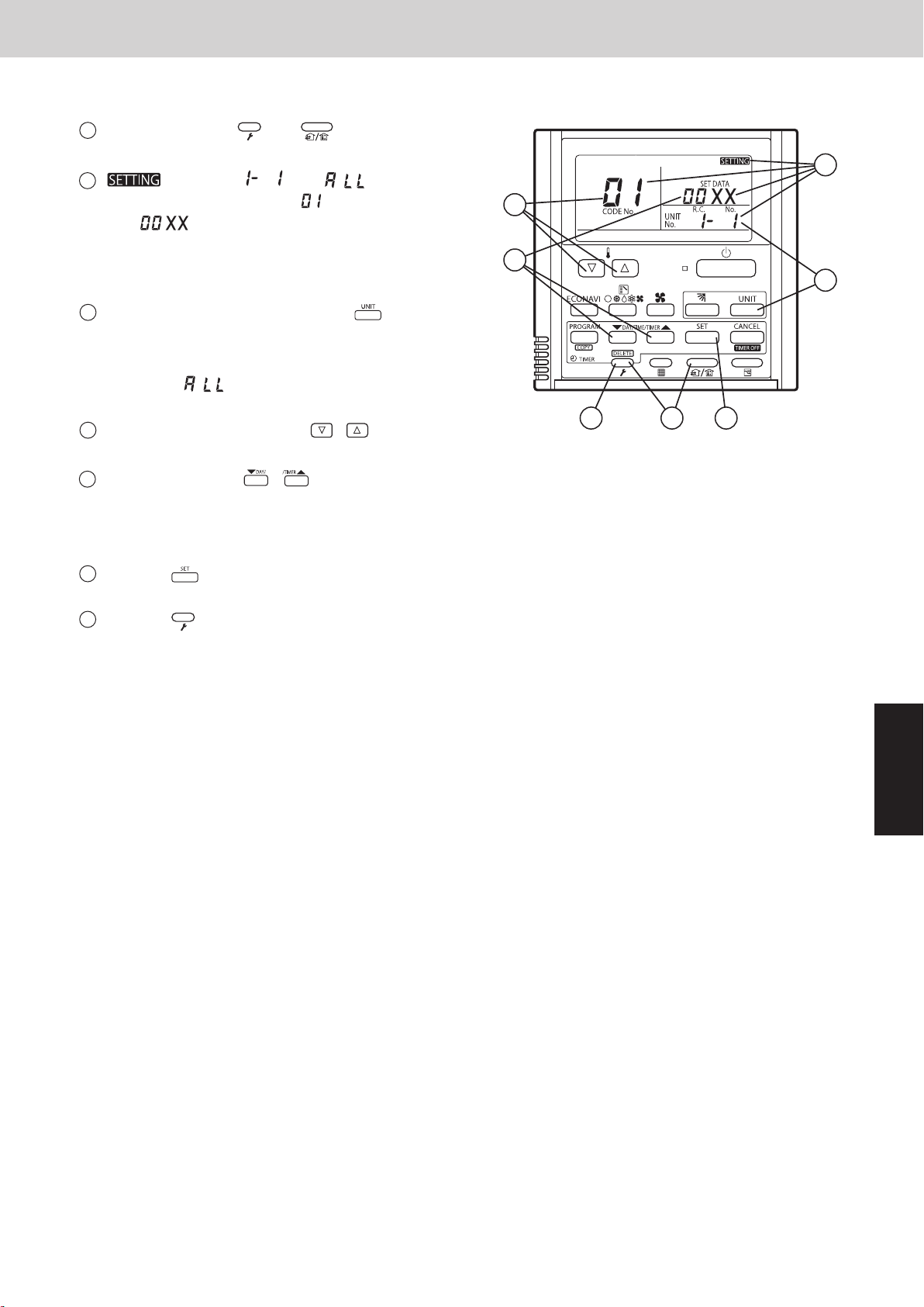
1. Simple Settings Function
<Procedure of CZ-RTC4>
Press and hold the and buttons
1
simultaneously for 4 seconds or longer.
“ ”, unit No.“ ” (or “” in the case
2
of group control), item code “ ”, and settings
data “” are displayed blinking on the remote
controller LCD display. At this time, the indoor unit
fan (or all indoor unit fans in the case of group
control) begins operating.
If group control is in effect, press the
3
select the address (unit No.) of the indoor unit to set.
At this time, the fan at the indoor unit begins operating.
*If unit No.“ ” is displayed, the same setting
will be made for all indoor units.
Press the temperature setting /
4
select the item code to change.
Press the timer time / buttons to select the
5
desired setting data.
*For item codes and setting data, see the following
page.
button and
buttons to
Mini VRF SYSTEM
Remote Controller Functions
°
4
°
5
A
CZ-RTC4
17 6
2
3
Press the button. (The display stops blinking
6
and remains lit, and setting is completed.)
7
Press the button to return to normal remote
controller display.
5
5 - 3
Page 96
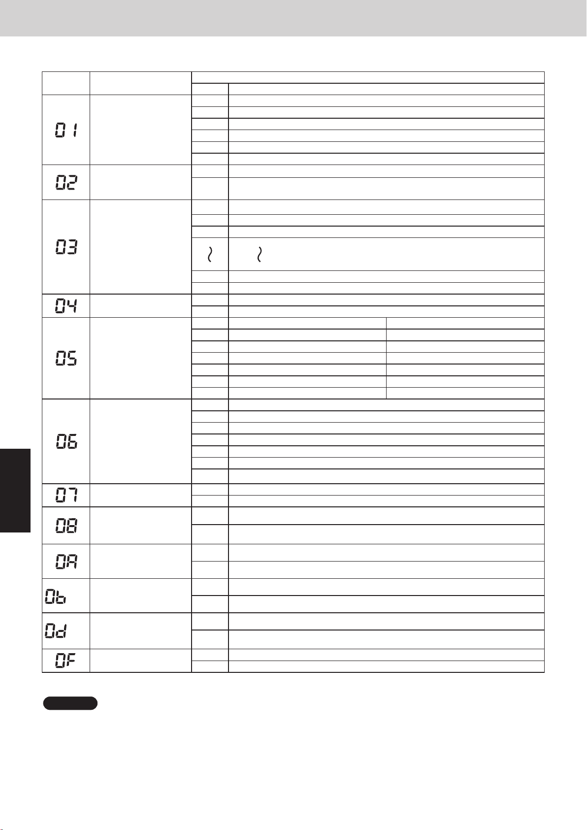
1. Simple Settings Function
List of Simple Setting Items
Item code Item
Filter sign ON time
(filter life time)
Degree of filter fouling
Central control
address
Operating mode
priority change
Fan speed when
heating thermostat is
OFF
Heating intake
temperature shift
5
(0B)
(0D)
Electric heater
installation
Humidifying when
heater thermostat is
OFF
Change to remote
controller sensor
thermostat differential
Function of EXCT
plug short-circuit
Permit/prohibit
automatic
heating/cooling
Cool-only
Mini VRF SYSTEM
Remote Controller Functions
Setting data
No. Description
0000 Not displayed
0001 150 hours
0002 2,500 hours
0003 5,000 hours
0004 10,000 hours
0005 Use the filter clogging sensor.
0000 Standard (setting at time of shipping)
Highly fouled
0001
(Filter sign ON time is reduced to one-half the set time.)
0001 Central control address 1
0002 Central control address 2
0003 Central control address 3
0064 Central control address 64
0099 No central control address set (setting at time of shipping)
0000 Normal (setting at time of shipping)
0001 Priority
Compressor ON Compressor OFF
0000 L 1 min., LL 3 min. LL
0001 L LL
0002 LL LL
0004 L 1 min., LL 3 min. L
0005 L L
0006 LL L
0000 No shift
0001 Shifts intake temperature 1°C down.
0002 Shifts intake temperature 2°C down.
0003 Shifts intake temperature 3°C down.
0004 Shifts intake temperature 4°C down.
0005 Shifts intake temperature 5°C down.
0006 Shifts intake temperature 6°C down.
0000 No heater
0001 Heater installed
0000 No (setting at time of shipping)
0001 Ye s
0000 Thermostat OFF differential: − 1°C (setting at time of shipping)
0001 Thermostat OFF differential: − 0.5°C
0000 Indoor unit does thermostat OFF (factory preset mode)
0001 Indoor unit gives “P14” alarm and transmits the refrigerant leakage signal.
0000 Permit
0001 Prohibit
0000 Normal
0001 Cool only (Set “1” for item code OD.)
NOTE
• In order to avoid water leakage and damage to the fan, do not set for humidifying when the thermostat is OFF unless a
vaporizing humidifier is used.
• Consider the device purpose and type when changing the settings. Incorrect settings may result in malfunction.
• Do not change any setting data that does not appear in this list.
5 - 4
Page 97
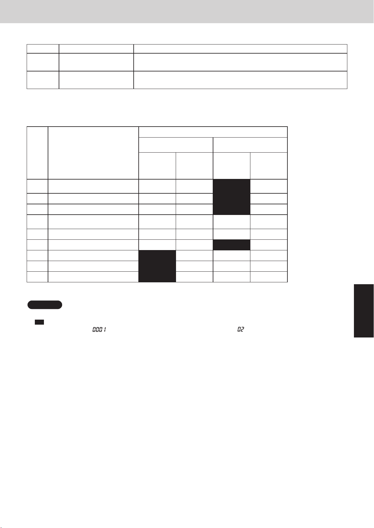
1. Simple Settings Function
Simple setting items
Item code Item Description
01
Filter sign ON time setting
(filter lifetime)
Changes the indoor unit filter lifetime when a high-performance filter or other
optional product is installed.
Mini VRF SYSTEM
Remote Controller Functions
02 Degree of filter fouling
Reduces the filter sign ON time to 1/2 of the standard time (setting at the time of
shipping) for cases when filter fouling is more severe than normal.
Filter sign ON times for each model
Filter sign ON time
Model
data
4-Way cassette (U1)
0001
4-Way cassette 60×60 (Y2)
0002 2-Way cassette (L1) × × 2500 1250
0003 1-Way cassette (D1) × × 2500 1250
Low Silhouette Ducted (F2)
0005
Slim Low Static Ducted (M1)
0006 High Static Pressure Ducted (E2) × × × ×
0007 Ceiling (T2) × × 1500 750
0008 Wall Mounted (K1, K2) 150 75 × ×
Model
Standard Long-life
Standard High fouling Standard High fouling
× × 2500 1250
× × × ×
0010 Floor Standing (P1) 150 75 × ×
0011 Concealed Floor Standing (R1) 150 75 × ×
Unit: hour
NOTE
•
indicates that there is no corresponding filter.
×
150
•
indicates the filter sign ON time that is set at shipment.
• High fouling: Set when
is selected for the degree of filter fouling (item code ).
5
5 - 5
Page 98

Mini VRF SYSTEM
1. Simple Settings Function
Item code Item Description
Set when using a central control device.
03 Central control address
04 Operating mode priority change Note (1)
NOTE
(1) Explanation of operation mode priority change
Enabled only in 2WAY System heat-pump models.
<Function>
With indoor units that are installed in combination with an outdoor unit model where either heating or cooling
operation can be selected, the operating mode of the indoor unit that starts first takes priority. The first indoor unit
to operate can select any operating mode. When any mode other than fan mode is selected, then the operating
modes that cannot be selected are not displayed on all remote controllers that are subsequently operated.
“Operation change control in progress” is displayed, indicating that there are restrictions on the operating
modes that can be selected.
Used when setting the central control address manually from the
remote controller.
Remote Controller Functions
•
Controlling the operating mode from a specific remote controller
- When there are multiple remote controllers in the same refrigerant system, it is possible to set one remote
controller as the priority remote controller (the remote controller which is given priority for selecting the
operating mode). (If 2 or more remote controllers are set as priority remote controllers, an alarm will occur at
the remote controllers, and operation will not be possible.)
- When the priority remote controller is set to the operating mode for control, then all other remote controllers can
select only the permitted operating mode, regardless of whether the priority remote controller is operating or
stopped.
- When a controlled remote controller is operated, “Operation change control in progress” is displayed.
Set mode at priority remote controller Modes that can be selected at other remote controllers
Cooling or dry Cooling, dry, fan
Heating Heating, fan
5
Fan Whichever mode (heating/cooling) is selected first
NOTE
There are other methods to avoid control in which the mode selected first takes priority.
Methods of remotely controlling the operating mode
(1) Use the central functions of a central control device.
(2) Use a remote control relay PCB at the outdoor unit.
5 - 6
Page 99

Mini VRF SYSTEM
1. Simple Settings Function
When the operating mode at the priority remote controller is changed, the operating modes of other remote
controllers change as shown below.
Mode change at priority remote controller Operating modes at other remote controllers
Current mode New mode Current mode New mode
Cooling or dry Heating
Heating Cooling
Cooling Dry
Heating Dry
Cooling or dry Fan
Heating Fan
Cooling or dry Heating
Fan Fan (not changed)
Heating Cooling
Fan Fan (not changed)
Cooling Cooling (not changed)
Dry Dry (not changed)
Heating Cooling
Fan Fan (not changed)
Cooling Cooling (not changed)
Dry Dry (not changed)
Fan Fan (not changed)
Heating Heating (not changed)
Fan Fan (not changed)
Remote Controller Functions
Item code Item Description
05
06
07 Electric heater installation
08
0D
0F Cooling-only
Fan speed setting when
heating thermostat is OFF
Heating intake temperature
shift
Humidifying when heater
thermostat is OFF
Permit/prohibit automatic
heating/cooling
Changes the fan speed setting when the heating thermostat is OFF.
Shifts the intake temperature during heating.
Can be set when the body thermostat is used.
Set when cost distribution is performed using an AMY central control system
or similar system, and when an optional electric heater is installed.
(This is unrelated to control of the electric heater.)
Normally humidifying does not occur when the thermostat is OFF during
heating operation. However, this setting can be changed in order to increase
the amount of humidifying.
Caution: In order to avoid water leakage and damage to the fan, do not use
this setting unless a vaporizing humidifier is used.
This setting can be used to prevent the automatic heating/cooling display on
the remote control if the unit configuration permits automatic heating/cooling
operation.
This setting allows a heat pump indoor unit to be operated as a cooling-only
unit.
5
5 - 7
Page 100
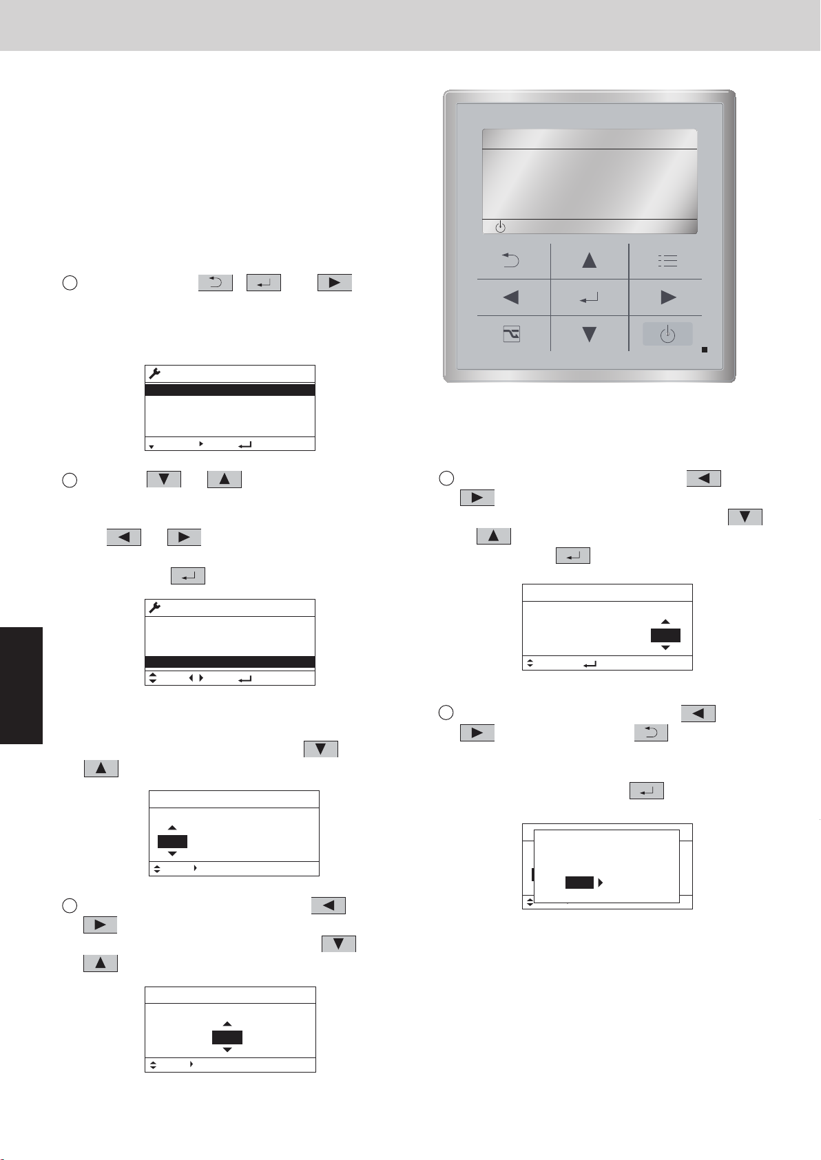
2. Detailed Settings Function
<Procedure of CZ-RTC4>
1
Press and hold the and , buttons
simultaneously for 4 seconds or longer.
2
“ ”, unit No. “ ”, item code “ ”, and
settings data “” are displayed blinking on the
remote controller LCD display. At this time, the indoor
unit fan begins operating.
3
If group control is in effect, press the
select the address (unit No.) of the indoor unit to set.
At this time, the fan at the indoor unit begins operating.
button and
*If unit No. “” is displayed, the same setting
will be made for all indoor units.
4
Press the temperature setting /
select the item code to change.
buttons to
5
Press the timer time / buttons to select the
desired setting data.
*For item codes and setting data, see the following
page.
6
Press the button. (The display stops blinking
and remains lit, and setting is completed.)
7
Press the button to return to normal remote
controller display.
CZ-RTC4
A
°
°
7 6
3
2
5
4
1
•
This allows the system address, indoor unit
address, and other settings to be made for the
individual or group-control indoor unit to which
the remote controller used for detailed settings is
connected.
When detailed settings mode is engaged,
operation stops at the individual or group-control
indoor unit where the remote controller used for
detailed settings is connected. Simple settings
items can also be set at this time.
<Procedure of CZ-RTC5>
Keep pressing the , and
1
buttonssimultaneously for 4 or more seconds.
The “Maintenance func” screen appears on the
LCD display.
Press the or button to see each
2
menu.
If you wish to see the next screen instantly, press
the or button.
Select “8. Detailed settings” on the LCD display
and press the button.
Maintenance func
1. Outdoor unit error data
2. Service contact
3. RC setting mode
4.Test run
Sel. Page [ ] Confirm
Maintenance func
5. Sensor info.
6. Servicing check
7. Simple settings
8. Detailed settings
Sel. Page [ ] Confirm
20:30 (THU)
20:30 (THU)
5
The “Detailed settings” screen appears on the
LCD display.
Select the “Unit no.” by pressing the or
button for changes.
Detailed settings
Unit no. Code no. Set data
3-1 0001
Sel. Next
Select the “Code no.” by pressing the or
3
button.
Change the “Code no.” by pressing the or
button (or keeping it pressed).
20:30 (THU)
10
Mini VRF SYSTEM
Remote Controller Functions
20:30 (THU)
[ ]
START
Select the “Set data” by pressing the or
4
button.
Select one of the “Set data” by pressing the
or button.
Then press the button.
5
Select the “Unit no.” by pressing the or
button and press the button.
The “Exit detailed settings and restart?” (Detailed
setting-end) screen appears on the LCD display.
Select “YES” and press the button.
Detailed settings
Unit no. Code no. Set data
3-1
[ ] Confirm
Sel.
Detailed settings
Exit detailed settings
Unit no. Code no. Set data
and restart?
ALL
Sel. Next
20:30 (THU)
10 0001
20:30 (THU)
01 0002
NOYES
CZ-RTC5
Detailed settings
Unit no. Code no. Set data
3-1 0001
Sel. Next
20:30 (THU)
10
5 - 8
 Loading...