

Panasonic SBHW-750-P Service manual
SB-HW750P
Colour
(K)... Black Type
(S)... Silver Type
ORDER NO. MD0702009CE
A6
Speaker System
Specification
Type 1 way, 1 speaker system (Bass reflex)
Speaker unit(s) Impedance 6 Ω
Subwoofer 16 cm (6-1/2”) cone type
Input power (IEC) 250 W (Max)
Output sound pressure 82 dB/W (1.0 m)
Frequency range 29 Hz - 220 Hz (-16 dB)
36 Hz - 180 Hz (-10 dB)
Dimensions (W x H x D) 178mm x 425mm x 257 mm
Mass 4kg(8.8lbs)
Notes :
1. Specifications are subject to change without notice.
Mass and dimensions are approximate.
2. Total harmonic distortion is measured by the digital spectrum
analyzer.
(7” x 16-23/32” x 10-1/8”)
CONTENTS
Page Page
1 System Combination
1.1. System Breakdown
1.2. Packaging Information
2 Assembling and Disassembling
2.1. Disassembly flow chart
2.2. Disassembly of Net frame assembly
2
2
2
3
3
4
2.3. Disassembly of Woofer
3 Connection of the Speaker Cables
4 Connection of the Wiring Diagram
5 Exploded view
5.1. Cabinet Parts Location
6 Replacement Parts List
11
4
5
8
9
9
© 2007 Matsushita Electric Industrial Co. Ltd.. All
rights reserved. Unauthorized copying and
distribution is a violation of law.
SB-HW750P
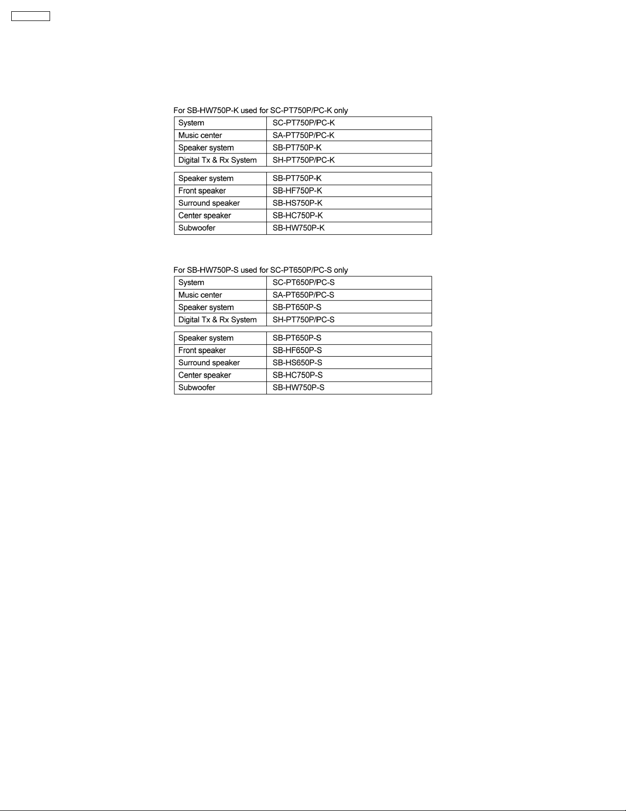
1 System Combination
1.1. System Breakdown
Note :
The diagrams below show the breakdown for speaker combinations used in main unit systems.
SB-PT750P-K consists of SB-HF750P-K (x2), SB-HS750P-K (x2), SB-HC750P-K (x1) & SB-HW750P-K (x1)
SB-PT650P-S consists of SB-HF650P-S (x2), SB-HS650P-S (X2), SB-HC750P-S (x 1) & SB-HW750P-S (x1)
1.2. Packaging Information
Note :
Please refer to service manual of SB-HF750P-K (MD0702006CE) and SB-HF650P-S (MD0702014CE) to understand the
packaging condition for SB-HW750P-K and SB-HW750P-S.
2
SB-HW750P
2 Assembling and Disassembling
“ATTENTION SERVICER”
Some chassis components may have sharp edges. Be careful when disassembling and servicing.
1. This section describes procedures for checking the operation of the major printed circuit boards and replacing the main
components.
2. For reassembly after operation checks or replacement, reverse the respective procedures.
Special reassembly procedures are described only when required.
3. Select items from the following index when checks or replacement are required.
4. Refer to the Parts No. on the page of “Parts Location and Replacement Parts List” (Section 6), if necessary.
Below is the list of disassembly sections
· Disasse mbly of Net frame assembly
· Disasse mbly of Woofer
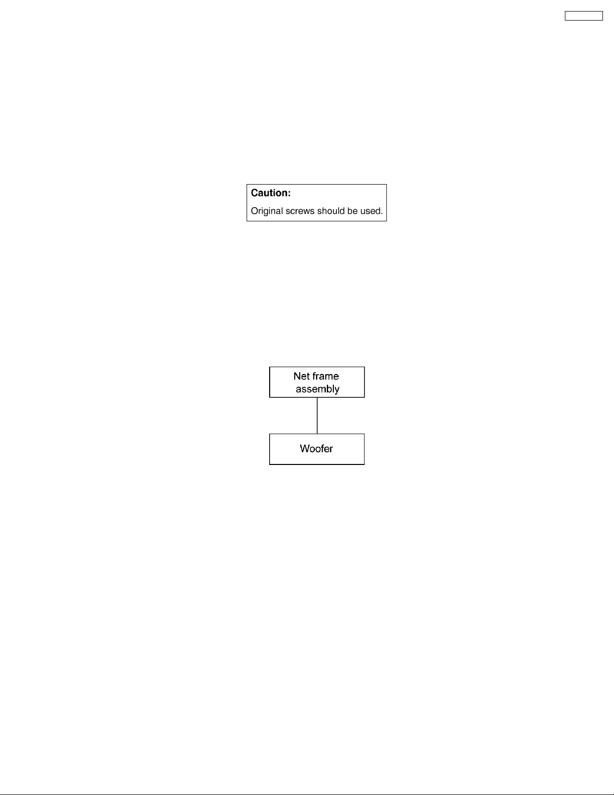
2.1. Disassembly flow chart
The following chart is the procedure for disassembling the casing and inside parts for internal inspection when carrying out the
servicing.
To assemble the unit, reverse the steps shown in the chart as below.
3
SB-HW750P
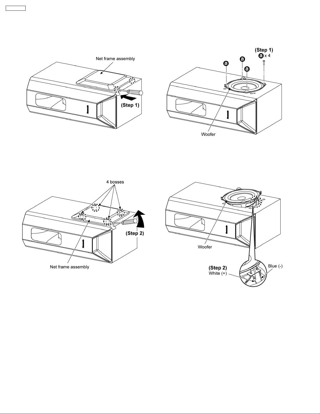
2.2. Disassembly of Net frame
assembly
2.3. Disassembly of Woofer
Follow (step 1) to (step 2) in item 2.2.
Step 1: Insert a flathead screwdriver above cloth at the grooves
of the net frame assembly.
Step 2: Apply light force along the bosses to push up the net
frame assembly.
Step 1: Remove 4 screws.
Step 2: Detach the blue (-) and white (+) wires.
4
 Loading...