

Panasonic SBHS-650-P Service manual
Specification
Type 1 way, 1 speaker system (Bass reflex)
Speaker unit(s) Impedance 3 Ω
Full range 6.5 cm (2-1/2”) cone type
Input power (IEC) 125* W (Max)
Output sound pressure 80 dB/W (1.0 m)
Frequency range 95 Hz to 25 kHz (-16 dB)
120 Hz to 22 kHz (-10 dB)
Dimensions (W x H x D) 92 x 142 x 95 mm
ORDER NO. MD0702015CE
A6
Speaker System
SB-HS650P
Colour
(S)... Silver Type
(3-5/8” x 5-19/32” x 3-3/4”)
Mass 0.6 kg (1.32lb.)
Notes :
1. Specifications are subject to change without notice.
Mass and dimensions are approximate.
2. Total harmonic distortion is measured by the digital spectrum
analyzer.
* : Rating with low-cut filter equipped amplifier.
CONTENTS
Page Page
1 System Combination
1.1. System Breakdown
1.2. Packaging Information
2 Assembling and Disassembling
2.1. Disassembly flow chart
2.2. Disassembly of Rear cabinet assembly
2
2
2
3
3
4
2.3. Disassembly of Woofer
3 Connection of the Speaker Cables
4 Connection of the Wiring Diagram
5 Exploded view
5.1. Cabinet Parts Location
6 Replacement Parts List
© 2007 Matsushita Electric Industrial Co. Ltd.. All
rights reserved. Unauthorized copying and
distribution is a violation of law.
10
10
11
5
6
9
SB-HS650P
1 System Combination
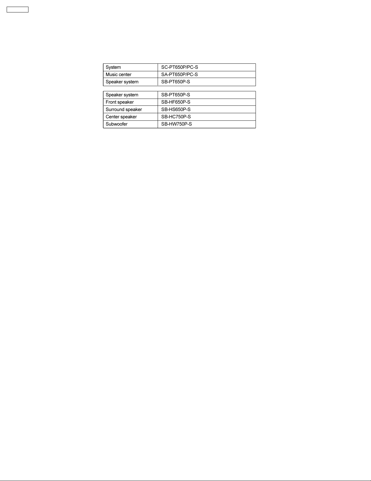
1.1. System Breakdown
Note :
The diagrams below show the breakdown for speaker combinations used in main unit systems.
SB-PT650P-S consists of SB-HF650P-S (x 2), SB-HS650P-S (x 2), SB-HC750P-S (x 1) & SB-HW750P-S (x 1)
1.2. Packaging Information
Note :
Please refer to service manual of SB-HF650P-K (MD0702014CE) to understand the packaging condition for SB-HS650P- K.
2
SB-HS650P
2 Assembling and Disassembling
“ATTENTION SERVICER”
Some chassis components may have sharp edges. Be careful when disassembling and servicing.
1. This section describes procedures for checking the operation of the major printed circuit boards and replacing the main
components.
2. For reassembly after operation checks or replacement, reverse the respective procedures.
Special reassembly procedures are described only when required.
3. Select items from the following index when checks or replacement are required.
4. Refer to the Parts No. on the page of “Parts Location and Replacement Parts List” (Section 6), if necessary.
Below is the list of disassembly sections
· Disasse mbly of Rear cabinet assembly
· Disasse mbly of Woofer
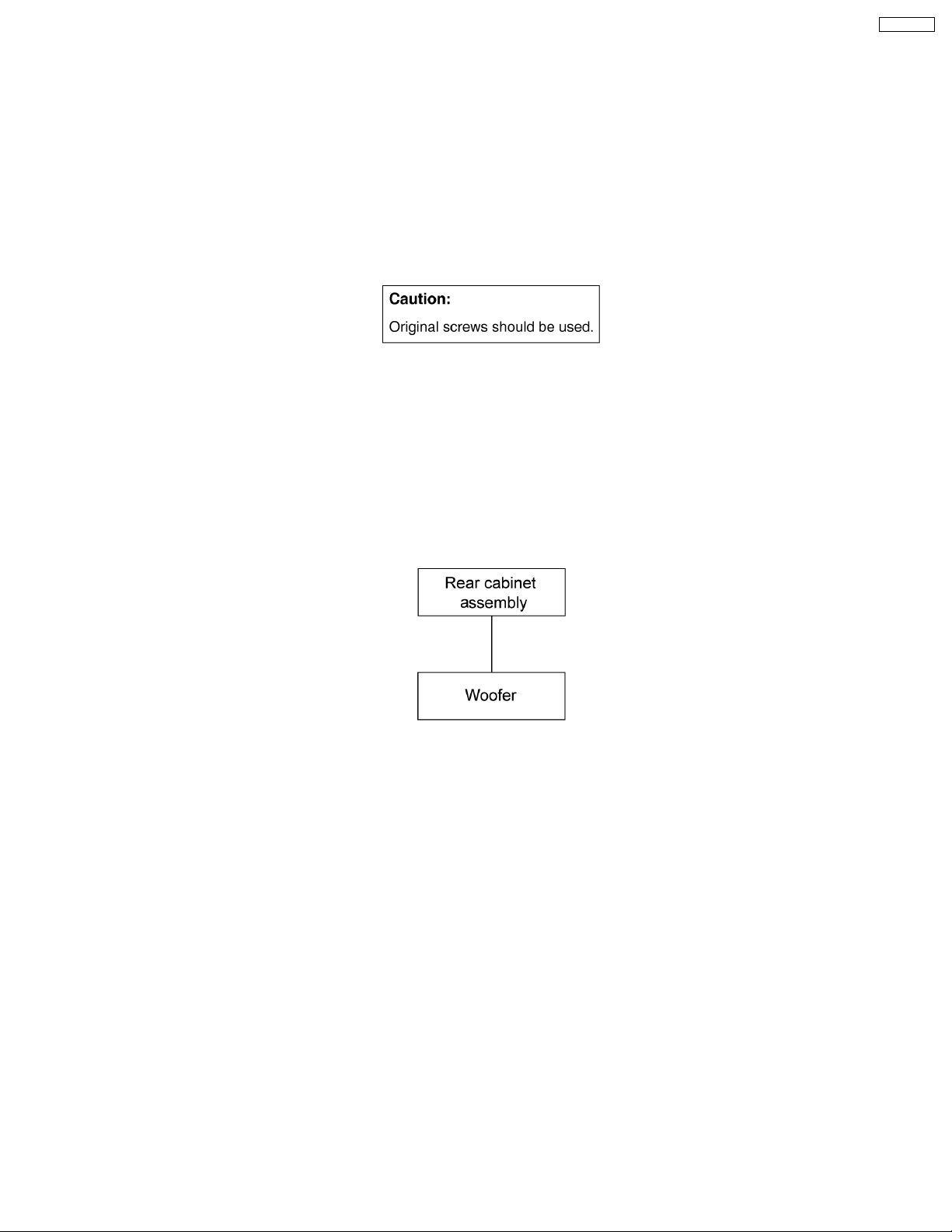
2.1. Disassembly flow chart
The following chart is the procedure for disassembling the casing and inside parts for internal inspection when carrying out the
servicing.
To assemble the unit, reverse the steps shown in the chart as below.
3
SB-HS650P
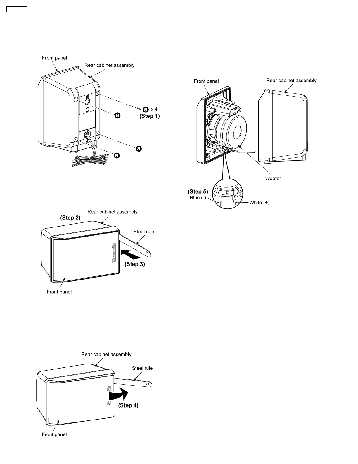
2.2. Disassembly of Rear cabinet
assembly
Step 4: Apply light force to push out the front panel as arrow
shown.
Caution:
Do not exert strong force as it may damage the rear cabinet
assembly.
Step 1: Remove 4 screws.
Step 2: Upset the speaker unit as shown above.
Step 3: Insert steel rule at the bottom corner of the rear cabinet
assembly as arrow shown.
Step 5: Detach the blue (-) and white (+) wires.
4
 Loading...