

Panasonic SBHF-850-G, SBPT-850-G Service manual
T
SB-HF850G
SB-PT850G
Colour
(K)... Black Type
ORDER NO. MD0705030CE
Speaker System
Specification
ype 2 way, 2 speaker system (Bass reflex)
Speaker unit(s) Impedance 6 Ω
1. Full range 6.5 cm cone type
2. Full range 6.5 cm cone type
Input power (IEC) 250 W* (Max)
Output sound pressure 83 dB/W (1.0 m)
Cross over frequency 5kHz
Frequencyrange 79 Hz to 25 kHz (-16 dB)
95 Hz to 22 kHz (-10 dB)
Dimensions (W x H x D) 252 x 1123 x 235 mm
Mass 3.8 kg
Notes :
1. Specifications are subject to change without notice.
Mass and dimensions are approximate.
2. Total harmonic distortion is measured by the digital spectrum
analyzer.
* : Rating with low-cut filter equipped amplifier.
© 2007 Matsushita Electric Industrial Co. Ltd.. All
rights reserved. Unauthorized copying and
distribution is a violation of law.
SB-HF850G
1 System Combination
1.1. System Breakdown
Note :
The table below show the breakdown for speaker combinations used in main unit systems.
System SC-PT850WGN-K
Music center SA-PT850GN-K
Front speaker
Surround speaker SB-HS851G-K
Center speaker SB-HC550E-K
Subwoofer SB-HW550E-K
Digital Tx & Rx system SH-PT850GN-K
SB-PT850G-K consists of SB-HF850G-K (x2), SB-HS851G-K (x2),
SB-HC550E-K (x1).
SB-HF850G-K
2
SB-HF850G
2 Assembling and Disassembling
“ATTENTION SERVICER”
Some chassis components may have sharp edges. Be careful when disassembling and servicing.
1. This section describes procedures for checking the operation of the major printed circuit boards and replacing the main
components.
2. For reassembly after operation checks or replacement, reverse the respective procedures.
Special reassembly procedures are described only when required.
3. Select items from the following index when checks or replacement are required.
4. Refer to the Parts No. on the page of “Parts Location and Replacement Parts List” (Section 6), if necessary.
Below is the list of disassembly sections
• Disassembly of Upper box assembly
• Disassembly of Upper rear cabinet
• Disassembly of Woofer 1 (SP1)
• Disassembly of Woofer 2 (SP1)
• Disassembly of Terminal jack
• Disassembly of Lower box assembly
• Disassembly of Lower rear cabinet assembly
• Disassembly of Lower base stand assembly
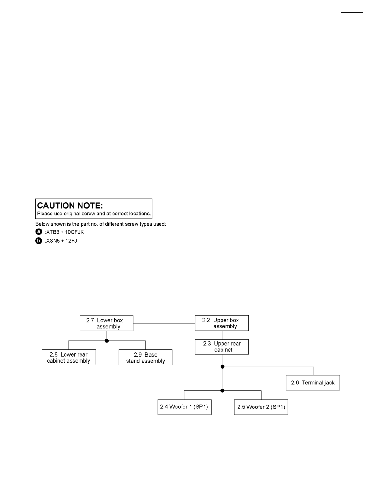
2.1. Disassembly flow chart
The following chart is the procedure for disassembling the casing and inside parts for internal inspection when carrying out the
servicing.
To assemble the unit, reverse the steps shown in the chart as below.
3
SB-HF850G
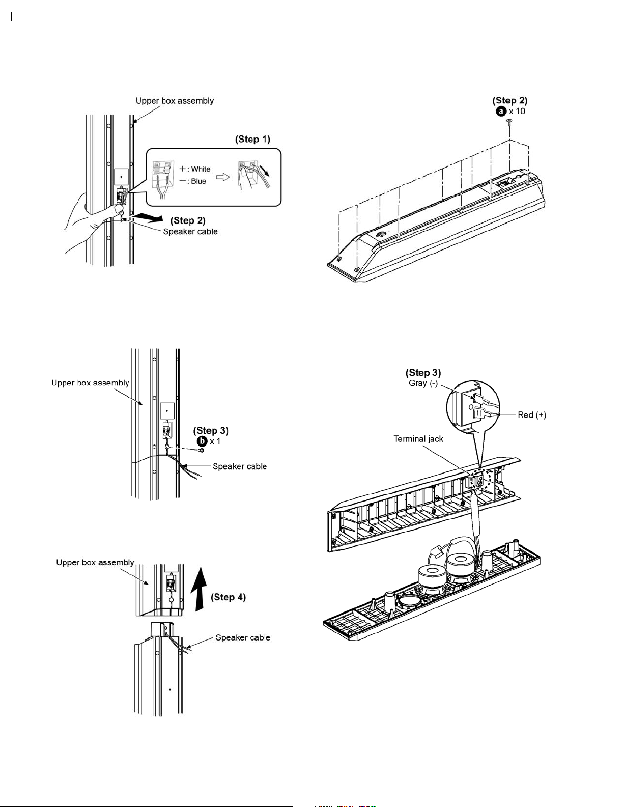
2.2. Disassembly of Upper box
assembly
Step 1: Remove the white (+) and blue (-) wires.
Step 2: Pull out the speaker cable from the groove.
2.3. Disassembly of Upper rear
cabinet
Step 1: Remove upper box assembly.
Step 2: Remove 10 screws.
Step 3: Remove screw.
Step 4: Remove the upper box assembly unit as arrow shown.
Step 3: Detach the gray (-) and red (+) wires.
4
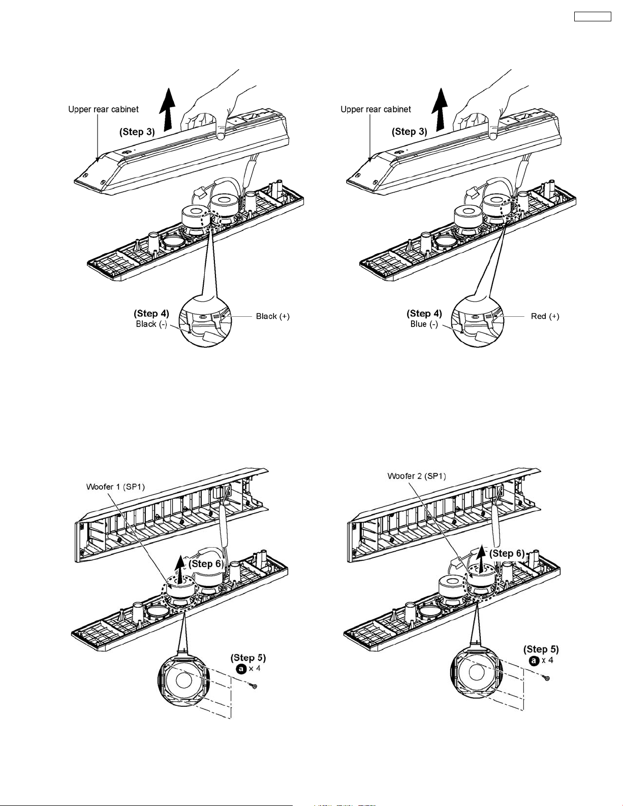
2.4. Disassembly of Woofer 1
(SP1)
SB-HF850G
2.5. Disassembly of Woofer 2
(SP1)
Step 1: Remove upper box assembly.
Step 2: Remove upper rear cabine t (Follow step 2).
Step 3: Lift up the upper rear cabine t as arrow shown.
Step 4: Detach black (+) and black (-) wires.
Step 1: Remove upper box assembly.
Step 2: Remove upper rear cabine t (Follow step 2).
Step 3: Lift up the upper rear cabine t as arrow shown.
Step 4: Detach red (+) and blue (-) wires.
Step 5: Remove 4 screws.
Step 6: Remove woofer 1 (SP1) as arrow shown.
Step 5: Remove 4 screws.
Step 6: Remove woofer 2 (SP1) as arrow shown.
5
 Loading...