

Panasonic SAXR-707-P Service manual
I
Rated
1
Total
Power
Power
Load
Frequency
Home Theater Audio System
SA-XR707P
Colour
(K)... Black Type
ORDER NO. MD0706002CE
A1
Specification
AMPLIFIER SECTION
minimum sine wave RMS power output
20 Hz to 20 kHz both channels driven
0.09 % total harmonic distortion 100 W per channel
kHz continuou s power output both channels driven
0.09 % total harmonic distortion 105 W per channel
harmonic distortion
rated power at 20 Hz-20 kHz 0.09 % (6 Ω)
bandwidth
both channels driven, -3 dB 4Hzto88kHz
(6 Ω,0.9%)
output each channel driven
0.9 % total harmonic distortion at 1kHz
Front (L/R) 100 W (6 Ω)
Center 100 W (6 Ω)
Surround (L/R) 100 W (6 Ω)
Surround Back (L/R) 100 W (6 Ω)
impedance
Front (L/R)
AorB 6to8Ω
A and B 6to8Ω
BI-WIRE 6to8Ω
Center 6to8Ω
Surround (L/R) 6to8Ω
Surround Back (L/R) 6to8Ω
response
(6 Ω)
(6 Ω)
CD, AUX, TV/STB, VCR, DVD
RECORDER, BD/DVD PLAYED
DVD 6CH 4Hzto44kHz,±3dB
Input sensitivity
CD, AUX, TV/STB, VCR, DVD
RECORDER, BD/DVD/DVD 6CH
Input impedance
CD, AUX, TV/STB, VCR, DVD
RECORDER, BD/DVD/DVD 6CH
S/N (IHF A)
CD, TV/STB, BD/DVD PLAYED, DVD
RECORDER (Digital Input)
Tone controls
BASS 50 Hz, +10 to -10 dB
TREBLE 20 kHz, +10 to -10 dB
Subwoofer frequency response (-6 dB) 7 Hz to 200 Hz
Digital input
(Optical) 2
(Coaxial) 2
HDMI (version 1.2a)
(Input) 2
(Output) 1
I FM TUNER SECTION
Frequency range 87.9 to 107.9 MHz
Sensitivity 11.2 dBf
50 dB quieting sensitivity
4Hzto88kHz,±3dB
27 mV
(200mV, IHF ’66)
22 kΩ
85 dB
(103 dB, IHF ’66)
(2 µV, IHF ’58)
© 2007 Matsushita Electric Industrial Co. Ltd.. All
rights reserved. Unauthorized copying and
distribution is a violation of law.
SA-XR707P
MONO 18.3 dBf
(4.5 µV, IHF ’58)
STEREO 38.3 dBf
(45 µV, IHF ’58)
Total harmonic distortion
MONO 0.2%
STEREO 0.3%
S/N
MONO 73 dB
STEREO 67 dB
Frequency response 20 Hz to 15 kHz,
Alternate channel selectivity 65 dB
Capture ratio 1.5 dB
Image rejection at 98 MHz 40 dB
Spurious response rejection at 98 MHz 75 dB
AM suppressio n 50 dB
Stereo separation
1 kHz 40 dB
10 kHz 30 dB
Antenna terminal 75 Ω (unbalanced)
I AM TUNER SECTION
Frequency range 530 to 1710 kHz
Sensitivity 20 µV, 330 µV/m
Selectivity 55 dB
IF rejection at 1000 kHz 50 dB
I VIDEO SECTION
Output voltage at 1 V input (unbalanced) 1±0.1 Vp-p
+1 dB, -2dB
Maximum input voltage 1.5 Vp-p
Input/output impedance 75 Ω
S-Video
Input BD/DVD PLAYED,
DVD RECORDER,
TV/STB, AUX
Output TV MONITOR
Component Video
Input DVD RECCORDER,
TV/STB
Output TV MONITOR
I GENERAL
Power supply AC 120 V, 60 Hz
Power consumpti on 140 W
Dimensions (W × H × D) 430 mm × 107.5 mm ×
390 mm
(16-15/16” × 4-7/32” × 15-11/32”)
Mass (Weight) Approx.
5.3 kg (11.7 lb.)
I DIN POWER
1 kHz, T.H. D. 1% 2 x 100 W (6 Ω)
Power consumpti on in standby mode: 0.7 W
Power consumpti on in HDMI off mode: 0.3 W
Notes:
1. Specifications are subject to change without notice.
2. Total harmonic distortion is measured by the digital spectrum
analyzer.
CONTENTS
Page Page
1 Safety Precaution s
2 Prevention of Electro Static Discharge (ESD) to
Electrostatically Sensitive (ES) Devices
3 Service caution based on legal restrictions
4 Accessories
5 Operating Instructions Procedures
6 Self Diagnosis Display Function
7 HDMI Checking Method
8 Assembling and Disassembling
9 Voltage Measurement & Waveform Chart
3
10 Wiring Connection Diagram
11 Block Diagram
12 Notes Of Schematic Diagram
5
13 Schematic Diagram
6
14 Printed Circuit Board Diagrams
7
15 Illustration of IC’s, Transistors and Diodes
8
16 Terminal Function of IC’s
21
17 Exploded Views
24
18 Replacement Parts List
29
47
2
65
67
75
77
109
119
120
123
127
SA-XR707P
1 Safety Precautions
1.1. GENERAL GUIDELINES
1. When servicing, observe the original lead dress. If a short circuit is found, replace all parts which have been overheated or
damaged by the short circuit.
2. After servicing, ensure that all the protective devices such as insulation barriers, insulation papers shields are properly installed.
3. After servicing, check for leakage current checks to prevent from being exposed to shock hazards.
(This “Safety Precaution” is applied only in U.S.A.)
1. Before servicing, unplug the power cord to prevent an electric shock.
2. When replacing parts, use only manufacturer’s recommended components for safety.
3. Check the condition of the power cord. Replace if wear or damage is evident.
4. After servicing, be sure to restore the lead dress, insulation barriers, insulation papers, shields, etc.
5. Before returning the serviced equipment to the customer, be sure to make the following insulation resistance test to prevent the
customer from being exposed to a shock hazard.
1.1.1. LEAKAGE CURRENT COLD CHECK
1. Unplug the AC cord and connec t a jumper between the two prongs on the plug.
2. Using an ohmmeter measure the resistance value, between the jumpered AC plug and each exposed metallic cabinet part on
the equipment such as screwheads, connectors, control shafts, etc. When the exposed metallic part has a return path to the
chassis, the reading should be between 1MΩ and 5.2Ω.
When the exposed metal does not have a return path to the chassis, the reading must be
.
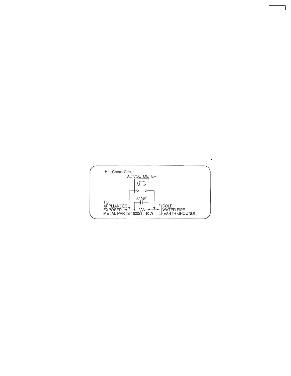
Figure. 1
1.1.2. LEAKAGE CURRENT HOT CHECK (See Figure 1.)
1. Plug the AC cord directly into the AC outlet. Do not use an isolation transformer for this check.
2. Connect a 1.5kΩ, 10 watts resistor, in parallel with a 0.15µF capacitors, between each exposed metallic part on the set and a
good earth ground such as a water pipe, as shown in Figure 1.
3. Use an AC voltmeter, with 1000 ohms/volt or more sensitivity, to measure the potential across the resistor.
4. Check each exposed metallic part, and measure the voltage at each point.
5. Reverse the AC plug in the AC outlet and repeat each of the above measurements.
6. The potential at any point should not exceed 0.75 volts RMS. A leakage current tester (Simpson Model 229 or equivalent) may
be used to make the hot checks, leakage current must not exceed 1/2 milliamp. should the measurement is outside of the limits
specified, there is a possibility of a shock hazard, and the equipment should be repaired and re-checked before it is returned
to the customer.
1.2. Before Repair and Adjustment
Disconnect AC power, discharge Power Supply Capacitors C707, C717, C718, C725 and C924 through a 10Ω, 1W resistor to
ground.
DO NOT SHORT-CIRCUIT DIRECTLY (with a screwdriver blade, for instance), as this may destroy solid state devices.
After repairs are completed, restore power gradually using a variac, to avoid overcurrent.
• Current consumption at AC 120V, 60 Hz in NO SIGNAL mode (at volume minimum) should be 200 ~ 600 mA.
3
SA-XR707P
1.3. Protection Circuitry
The protection circuitry may have operated if either of the following conditions are noticed:
• No sound is heard when the power is turned on.
• Sound stops during a performance.
The function of this circuitry is to prevent circuitry damage if, for example, the positive and negative speaker connection wires are
"shorted", or if speaker systems with an impedance less than the indicated rated impedance of the amplifier are used.
If this occurs, follow the procedure outlines below:
1. Turn off the power.
2. Determine the cause of the problem and correct it.
3. Turn on the power once again after one minute.
Note:
When the protection circuitry functions, the unit will not operate unless the power is first turned off and then on again.
1.4. Safety Part Information
Safety Parts List:
There are special components used in this equipment which are important for safety.These parts are marked by
Schematic Diagrams & Replacement Parts List. It is essential that these critical parts should be replaced with manufacturer’s
specified parts to prevent shock, fire or other hazards. Do not modify the original design without permission of manufacturer.
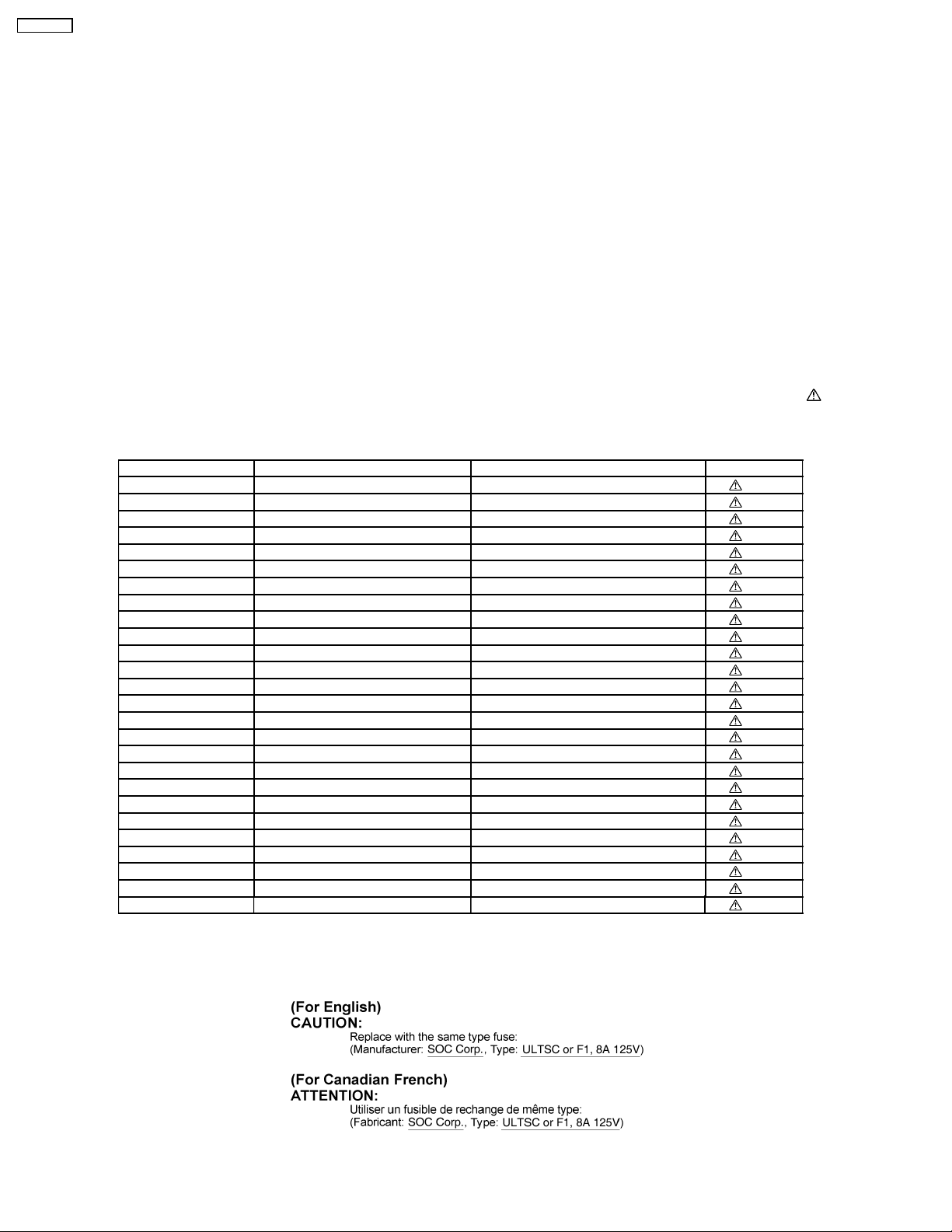
Table 1
Reference No. Part No. Part Name & Description Remarks
A2 K2CB2CB00018 AC CORD [M]
P701 K2AB2B000007 JK AC INLET [M]
T701 ETS48AA185AD MAIN TRANSFORMER [M]
T721 ETS25AD1P6AG BACKUP TRANSFORMER [M]
F1 K5D802AQ0001 FUSE [M]
C701 ECQU2A104MLC 0.1 100V [M]
C702 ECQU2A104MLC 0.1 100V [M]
C703 F1BAF2220006 2200P [M]
C704 F1BAF2220006 2200P [M]
C705 F1BAF1020020 1000P [M]
C706 ECQU2A104MLC 0.1 100V [M]
C714 F1BAF2220006 2200P [M]
L701 ELF18N067E COMMON MODE COIL [M]
L702 ELF21N024E LINE FILTER COIL [M]
L703 ELF21N024E LINE FILTER COIL [M]
RY721 K6B1AEA00003 PC POWER RELAY [M]
DZ701 ERZV10V511CS ZENER [M]
PC701 B3QAZ0000062 IC PHOTO COUPLE [M]
PC721 B3QAZ0000062 IC PHOTO COUPLE [M]
R701 ERC12UGK335D 3.3M 1/2W [M]
T731 ETS28AU3B9AC SUB TRANSFO RMER [M]
TH701 D4CAA2R20001 THERMIST OR [M]
TH702 D4CA33030001 THERMISTOR [M]
TH6101 D4CA33030001 THERMISTOR [M]
D701 B0FFKC000001 DIODE [M]
D711 B0HBSM000043 DIODE [M]
in the
1.5. Caution for fuse replacement
4

SA-XR707P
2 Prevention of Electro Static Discharge (ESD) to
Electrostatically Sensitive (ES) Devices
Some semiconductor (solid state) devices can be damaged easily by electricity. Such components commonly are called
Electrostatically Sensitive (ES) Devices. Examples of typical ES devices are integrated circuits and some field-effect transistors and
semiconductor “chip” components. The following techniques should be used to help reduce the incidence of component damage
caused by electro static discharge (ESD).
1. Immediately before handlin g any semiconductor component or semiconductor-equiped assembly, drain off any ESD on your
body by touchin g a known earth ground. Alternatively, obtain and wear a commercially available discharging ESD wrist strap,
which should be removed for potential shock reasons prior to applying power to the unit under test.
2. After removing an electrical assembly equiped with ES devices, place the assembly on a conduc tive surface such as aluminium
foil, to prevent electrostatic charge build up or exposure of the assembly.
3. Use only a grounded-tip soldering iron to solder or unsolder ES devices.
4. Use only an anti-static solder remover device. Some solder removal devices not classified as “anti-static (ESD protected)” can
generate electrical charge to damage ES devices.
5. Do not use freon-propelled chemicals. These can generate electrical charges sufficient to damage ES devices.
6. Do not remove a replacement ES device from its protective package until immediately before you are ready to install it. (Most
replacement ES devices are packaged with leads electrically shorted together by conductive foam, aluminium foil or
comparable conductive material).
7. Immediately before removing the protective material from the leads of a replacement ES device, touch the protective material
to the chassis or circuit assembly into which the device will be installed.
Caution
Be sure no power is applied to the chassis or circuit, and observe all other safety precautions.
8. Minimize body motions when handling unpackaged replacement ES devices. (Otherwise harmless motion such as the brushing
together of your clothes fabric or the lifting of your foot from a carpeted floor can generate static electricity (ESD) sufficient to
damage an ES device).
5

SA-XR707P
3 Service caution based on legal restrictions
3.1. General description about Lead Free Solder (PbF)
The lead free solder has been used in the mounting process of all electrical components on the printed circuit boards used for this
equipment in considering the globally environmental conservation.
The normal solder is the alloy of tin (Sn) and lead (Pb). On the other hand, the lead free solder is the alloy mainly consists of tin
(Sn), silver (Ag) and Copper (Cu), and the melting point of the lead free solder is higher approx.30 degrees C (86°F) more than that
of the normal solder.
Definition of PCB Lead Free Solder being used
The letter of “PbF” is printed either foil side or components side on the PCB using the lead free solder.
(See right figure)
Service caution for repair work using Lead Free Solder (PbF)
• The lead free solder has to be used when repairing the equipment for which the lead free solder is used.
(Definition: The letter of “PbF” is printed on the PCB using the lead free solder.)
• To put lead free solder, it should be well molten and mixed with the original lead free solder.
• Remove the remaining lead free solder on the PCB cleanly for soldering of the new IC.
• Since the melting point of the lead free solder is higher than that of the normal lead solder, it takes the longer time to melt
the lead free solder.
• Use the soldering iron (more than 70W) equipped with the temperature control after setting the temperature at 350±30
degrees C (662±86°F).
Recommended Lead Free Solder (Service Parts Route.)
• The following 3 types of lead free solder are available through the service parts route.
RFKZ03D01K-----------(0.3mm 100g Reel)
RFKZ06D01K-----------(0.6mm 100g Reel)
RFKZ10D01K-----------(1.0mm 100g Reel)
Note
* Ingredient: tin (Sn), 96.5%, silver (Ag) 3.0%, Copper (Cu) 0.5%, Cobalt (Co) / Germanium (Ge) 0.1 to 0.3%
6
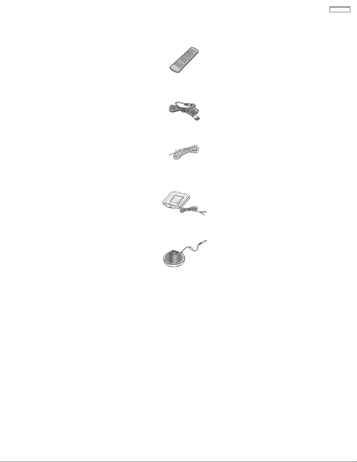
4 Accessories
Note : Refer to Replacement Parts List (Section 18) for the part number.
Remote
control
AC cord
FM antenna
wire
SA-XR707P
AM loop antenna
Calibration MIC
7
SA-XR707P
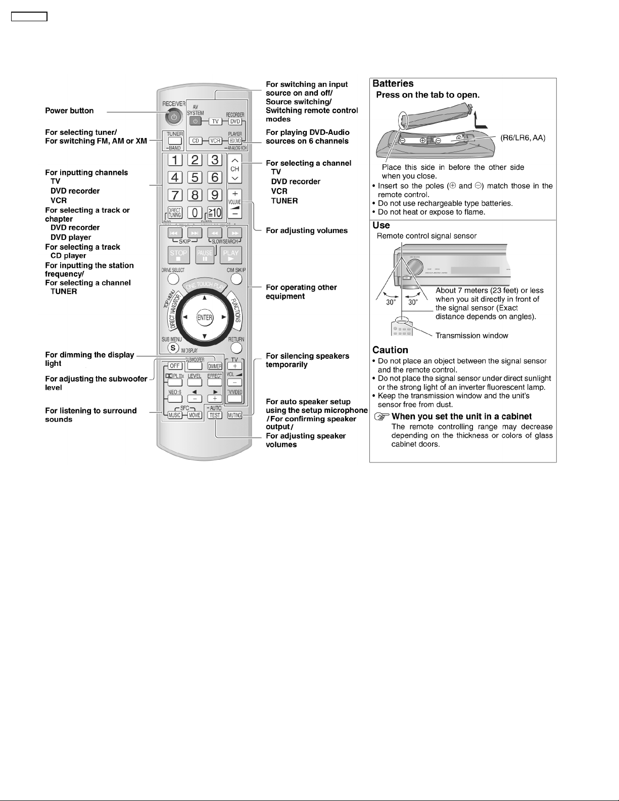
5 Operating Instructions Procedures
5.1. Remote Control Operation
8
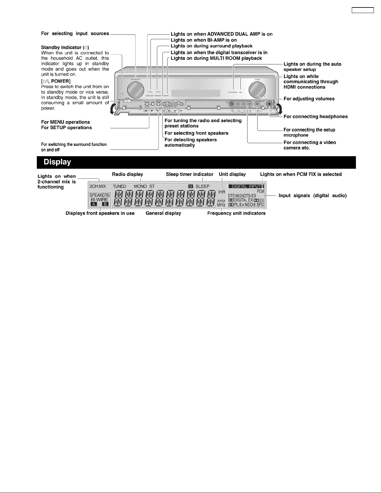
5.2. Main Unit Operation
SA-XR707P
9

SA-XR707P
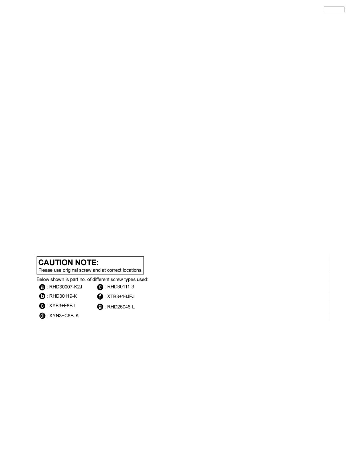
5.3. Main Unit Connections
5.3.1. TV and a DVD recorder/DVD player using HDMI cables
10
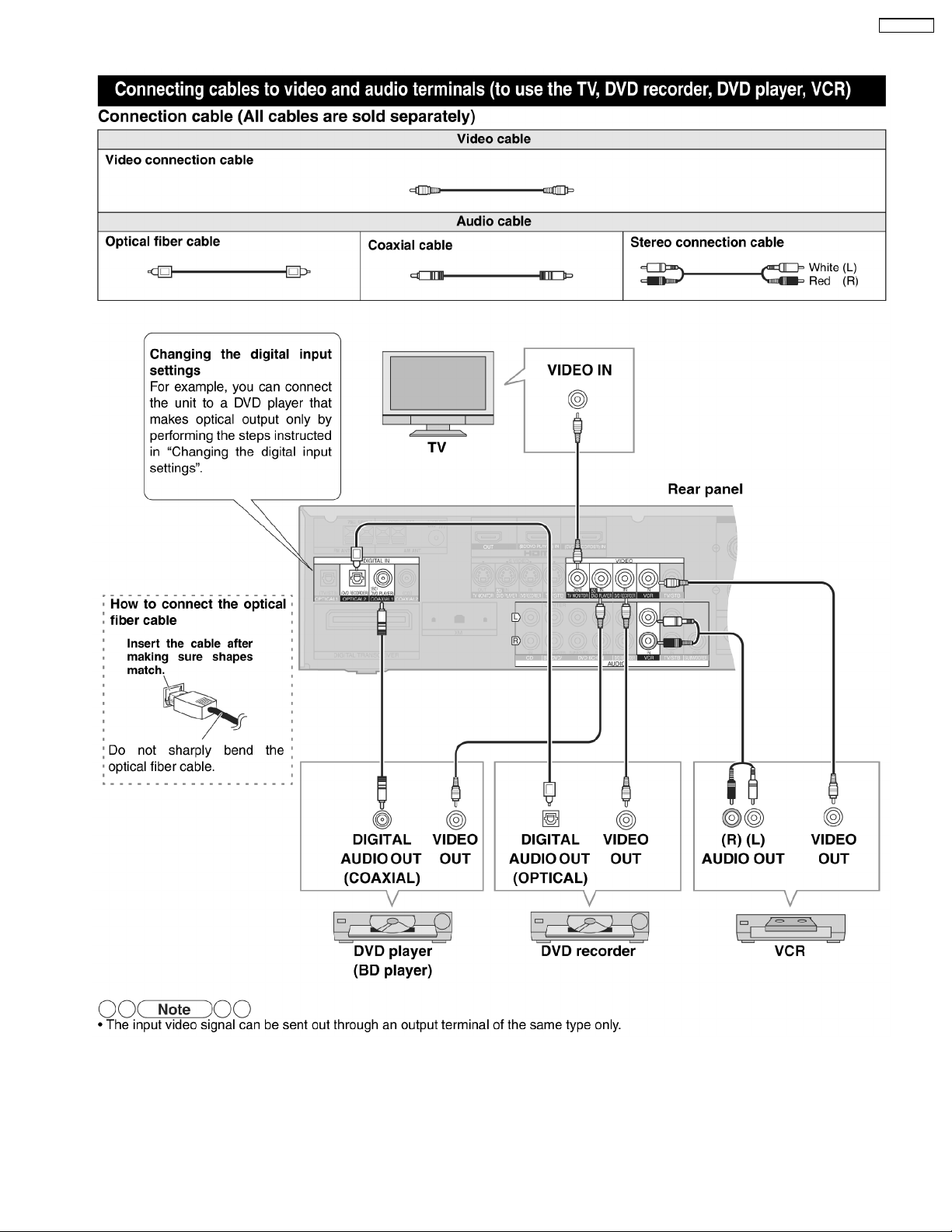
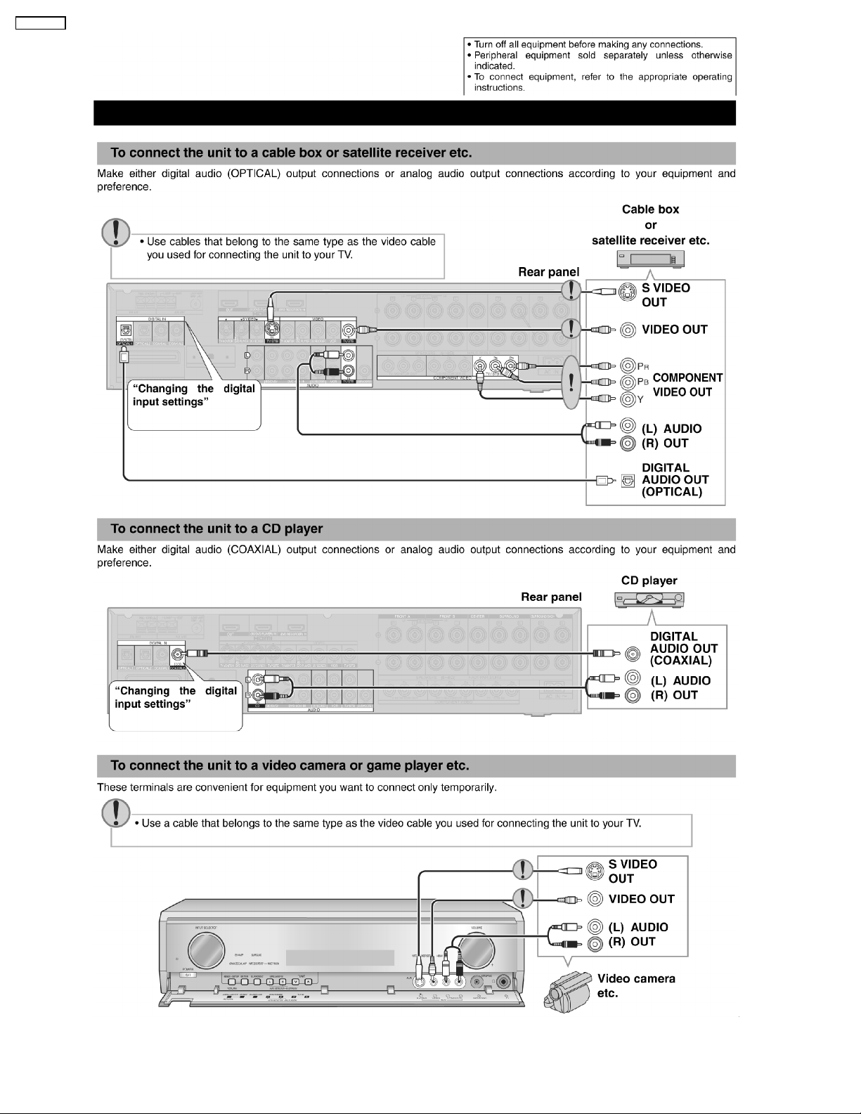
5.3.2. Video & Audio Terminals
SA-XR707P
11
SA-XR707P
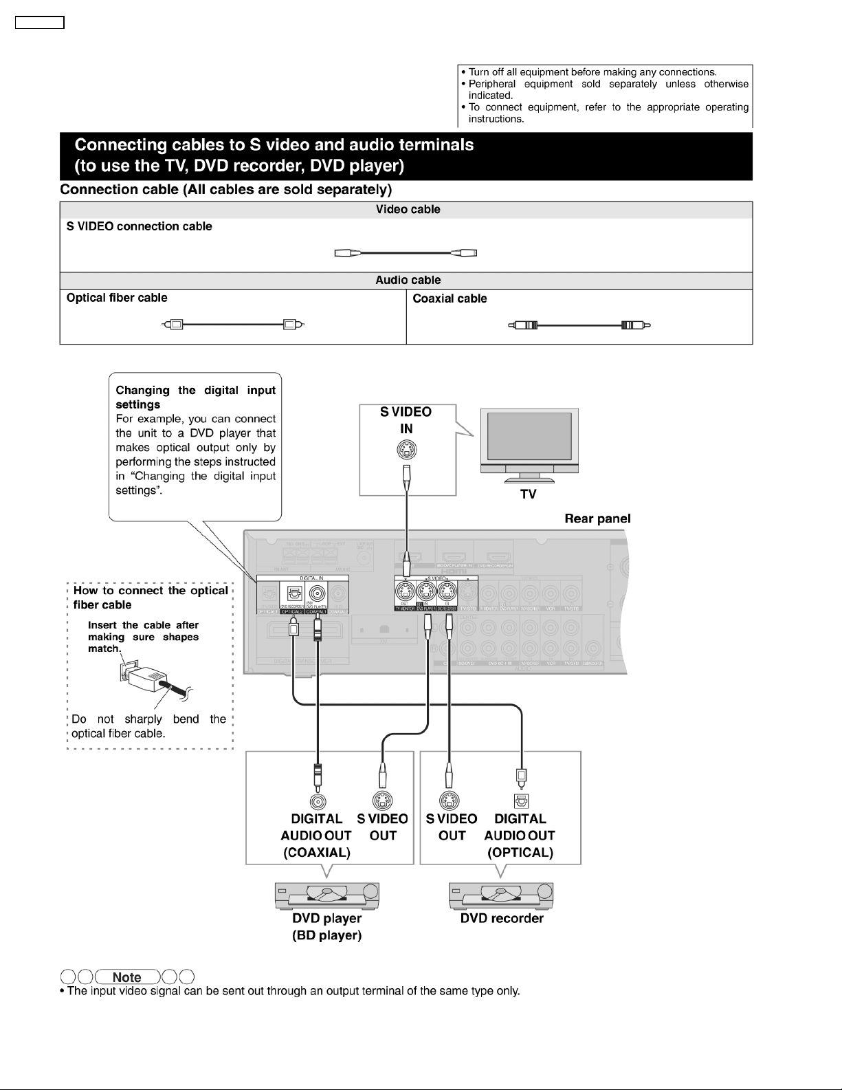
5.3.3. S-video & Audio Terminals
12
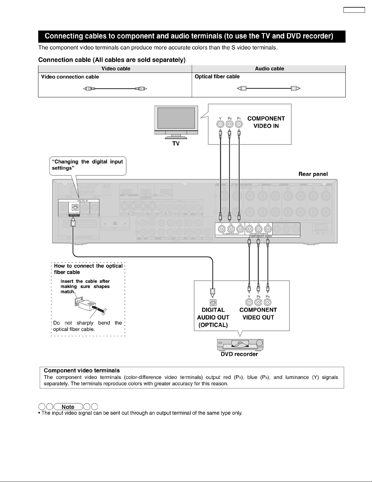
5.3.4. Component & Audio Terminals
SA-XR707P
13
SA-XR707P
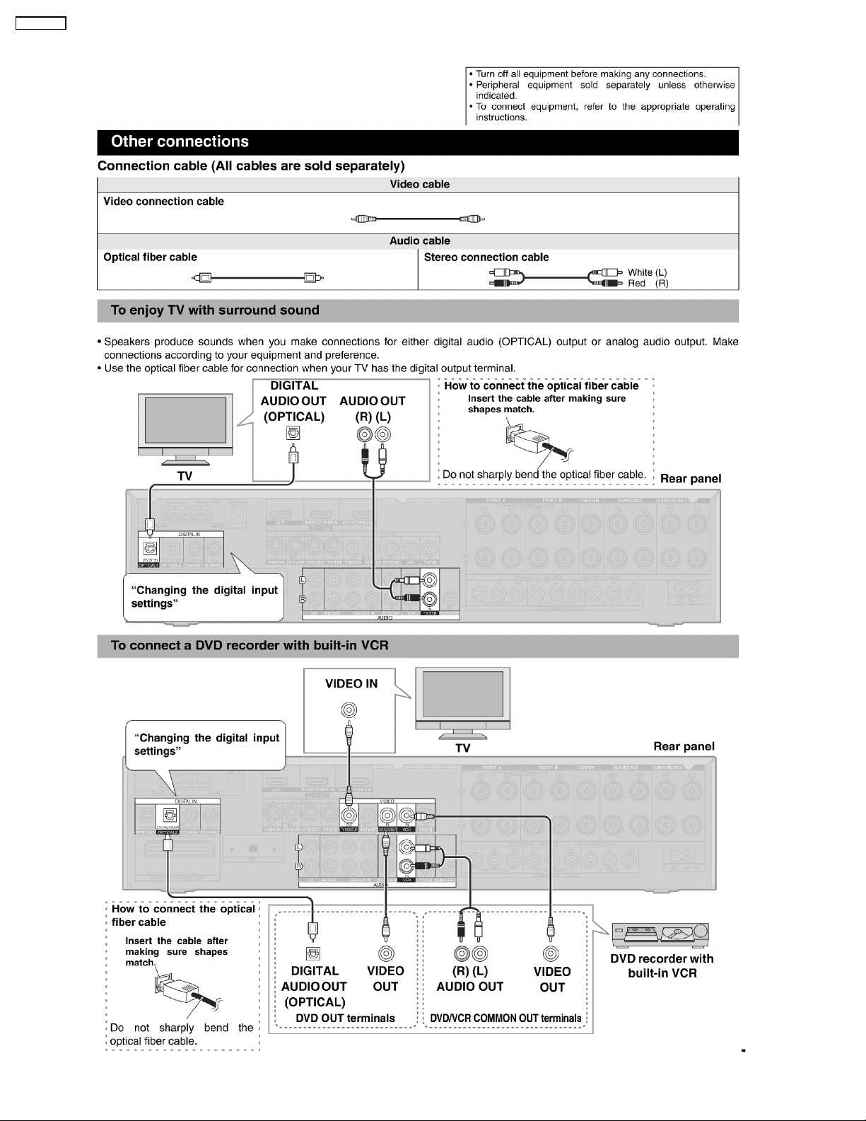
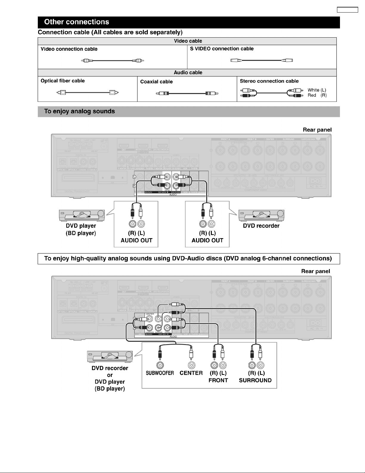
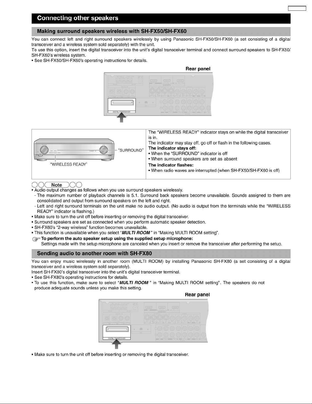
5.3.5. Other Connections
14
SA-XR707P
15
SA-XR707P
16
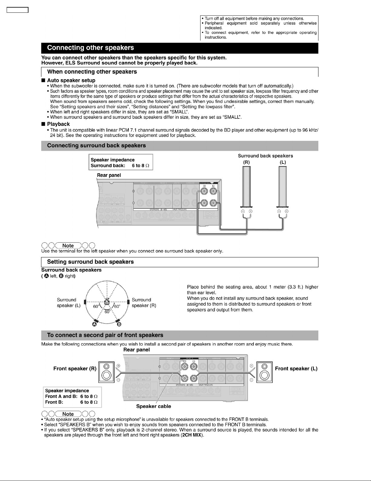
5.3.6. For Speakers
SA-XR707P
17
SA-XR707P
18
SA-XR707P
19
SA-XR707P
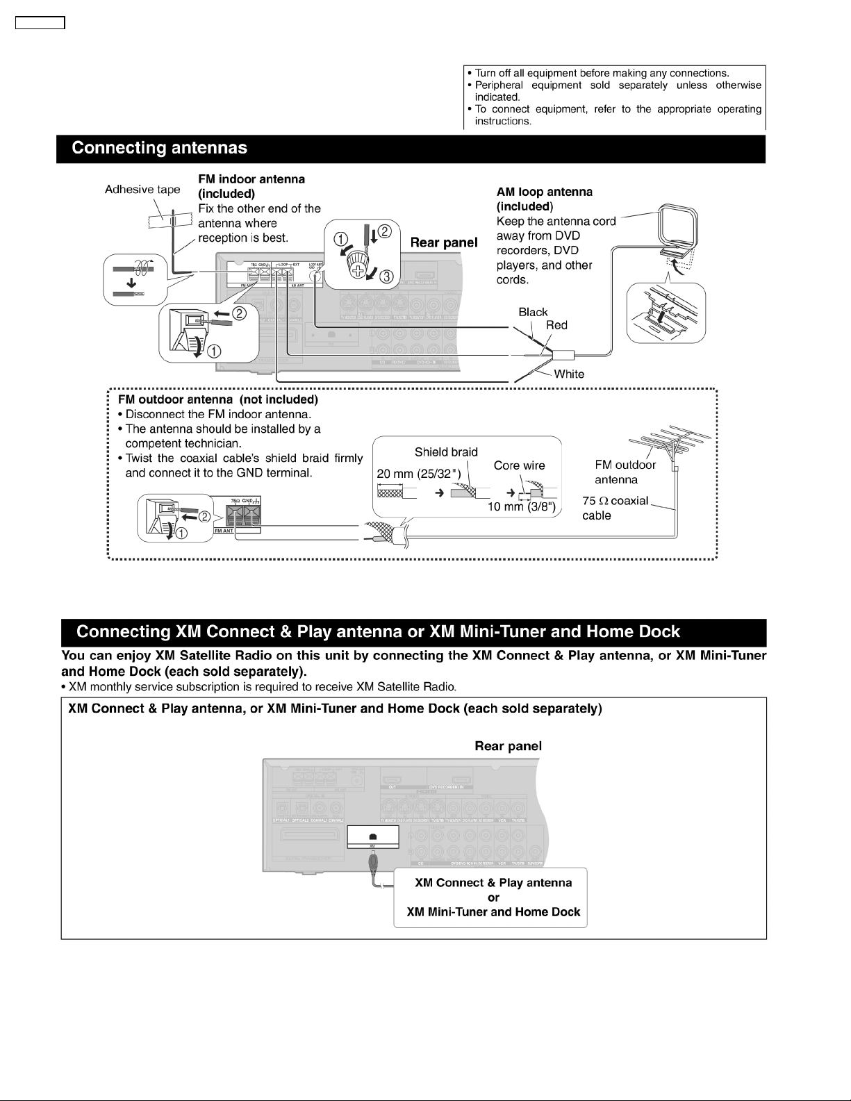
5.3.7. For FM/AM antennas
5.3.8. For XM connection
20
SA-XR707P
6 Self Diagnosis Display Function
This unit is equipped with features of self-diagnostic & special mode setting for checking the functions & reliability.
6.1. Service Mode Summary Table
The service modes can be activated by pressing various button combination on the main unit and remote control unit.Below is the
summary for the various modes for checking:
Player buttons Application Note
[MENU-SETUP, RETURN], [SPEAKER S A], [POWER]. Entering into Doctor Mode (Refer to the section “6.2. for more
[ENTER], [SPEAKERS A], [POWER]. Entering into Service Mode (Refer to the section “6.2. for more
6.2. Service Mode Table
Below is the various special modes for checking:-
Item FL Display Key Operation
Mode Name Description Front Key
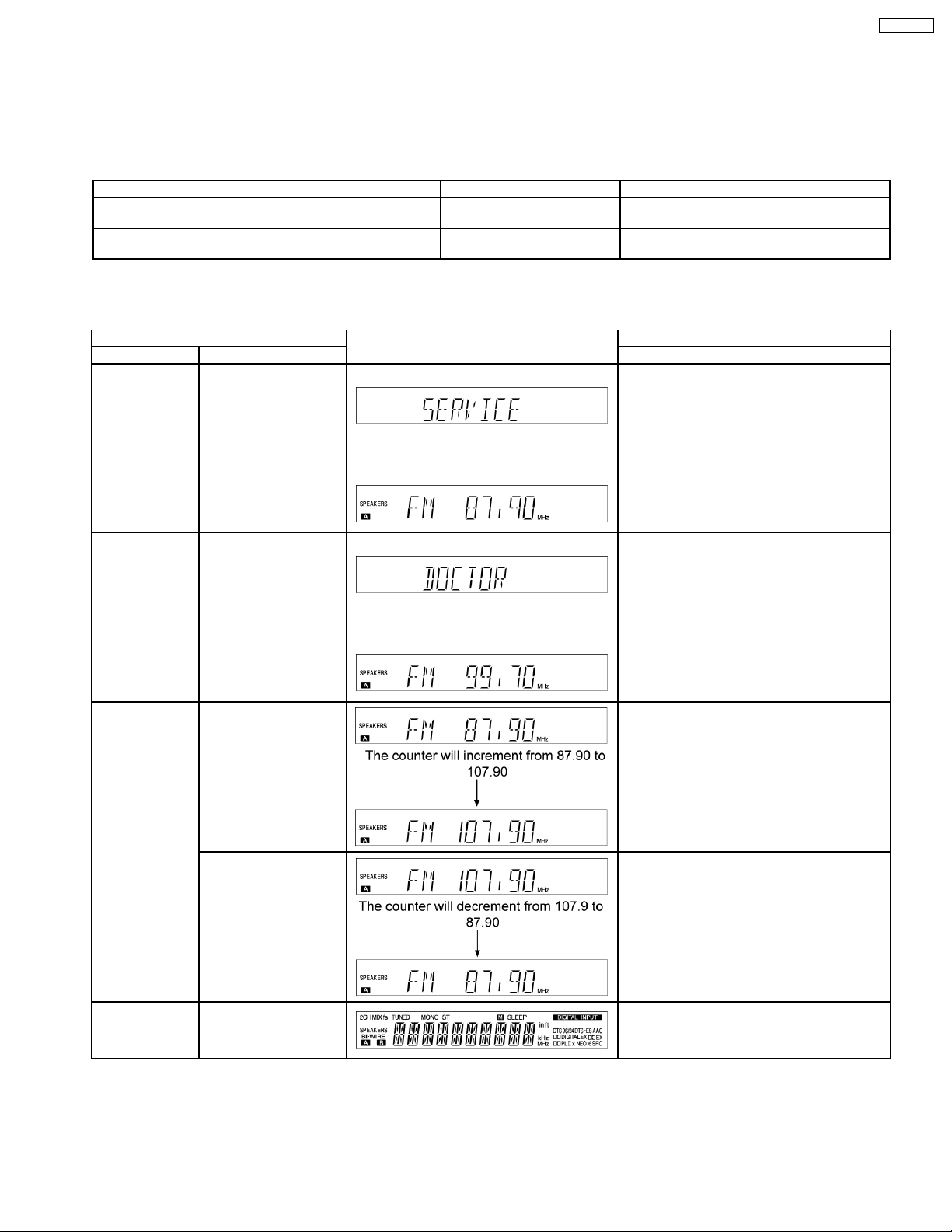
Service Mode To enter into Service
mode checking for main
unit.
FL display sequence
Display 1→2
(Display 1)
(Display 2)
The [FM 87.90] display will appear after 3s.
information.)
information.)
1. Press and hold down the [ENTER] button
and the [SPEAKERS A] button, and then
press the [POWER] button at the same
time. (Main Unit)
To exit Service Mode, press [POWER] button
on main unit or remote control.
Doctor Mode To enter into Doctor
Mode for checking of
various items.
FL display sequence
Display 1→2
Auto tuning check To auto tuning function is
started to upward.
To auto tuning function is
started to downward.
(Display 1)
(Display 2)
The [FM 99.70] display will appear after 3s.
1. Press and hold down the [MENU-SETUP,
RETURN] button and the [SPEAKER S A]
button, and then press the [POWER] button
at the same time. (Main Unit)
To exit Doctor Mode, press [POWER] button on
main unit or remote control.
1. Press [8] button on remote control.
To exit Doctor Mode, press [POWER] button on
main unit or remote control.
1. Press [9] button on remote control.
To exit Doctor Mode, press [POWER] button on
main unit or remote control.
FL Display Test To check the FL
segments display (All
segment will light up)
1. Press [0] button on remote control.
To exit Doctor Mode, press [POWER] button on
main unit or remote control.
21

SA-XR707P
Item FL Display Key Operation
Mode Name Description Front Key
Firmware version
& EEPROM
checksum
checking.
To check Main µP
software version
To check Sub µP
software version and
HDMI µP software
version are displayed at
each time pressing.
To confirm the HDMI µP
software version.
Doctor mode function at some remote control codes as below table.
6.3. Other inspection test
Remote Control Test Mode Function and settings
Selector Sound Mode other settings Vol/Tone
CH 1 TUNER STEREO Frequency : FM min (87.90) -48dB/0dB
CH 2 TUNER STEREO Frequency : FM max (107.90) -48dB/0dB
CH 3 TUNER STEREO FM 98.3MHz -18dB/0dB
CH 4 TUNER STEREO Frequency : AM min (530) -48dB/0dB
CH 5 TUNER STEREO Frequency : AM max (1710) -48dB/0dB
CH 6 TUNER STEREO AM 765kHz (9kHz/step) -18dB/0dB
CH 7 TUNER STEREO AM 770kHz (10kHz/step) -18dB/0dB
CH 8 If the input selector is TUNER, auto tuning function is started to upward on current frequency.
CH 9 If the input selector is TUNER, auto tuning function is started to downward on current frequency.
CH 0 All indicators of FL are displayed. All LED are off. Refer to Fig. 6.4.
CH UP Check Main µP software version.
CH DOWN Check µP software version and HDMI µP software version are displayed at each time pressing.
SUBWOOFER VCR (Analog) - All CH Output Mode -18dB/0dB
MUTING DVD 6CH - - -18dB/0dB
PLIIx CD STEREO Analog -18dB/0dB
NEO:6 TV/STB STEREO Analog -18dB/0dB
TV/VIDEO BD/DVD STEREO Analog -18dB/0dB
LEVEL DVR STEREO Analog -18dB/0dB
EFFECT CD STEREO Digital Input (COAX 2) -48dB/0dB
OFF TV/STB STEREO Digital Input (OPT 1) -48dB/0dB
SFC MOVIE DVD STEREO Digital Input (COAX 1) -48dB/0dB
SFC MUSIC DVR STEREO Digital Input (OPT 2) -48dB/0dB
TEST No change SURROUND If MIC is not insert, Scan the test noise output
-/L CD STEREO Balance is set to leftmost (COAX 2) -18dB/0dB
+/R CD STEREO Balance is set to rightmost (COAX 2) -18dB/0dB
DIMMER If the input selector is TUNER in E2 mode. Display Mode (PS/PTY) is changed.
Note : After this setting, only ‘POWER’ button or ‘Checker Command’ code by the remote control can be entered.
AUX STEREO If MIC is inserted, mic input is selected and it is
1. Press [CH UP] button on remote control.
To exit Doctor Mode, press [POWER] button on
main unit or remote control.
1. Press [CH DOWN] button on remote
control.
To exit Doctor Mode, press [POWER] button on
main unit or remote control.
1. Press [SURROUND] button on main unit.
To exit Doctor Mode, press [POWER] button on
main unit or remote control.
-18dB/0dB
channel with 500ms intervals.
-18dB/0dB
output to speaker in analog mode.
6.4. Error Code Table
The error code is automatically display after entering into self-diagnostic mode.
Error Code Diagnosis Contents Description of error Automatic FL Display Remarks
OVER
LOAD
F70 Abnormal
F76 Abnormal stabilized
Detection of
malfunction
communication
between peripneral
LSI and Micro-P
power supply
Speaker short, amplifier
failure. Humidity protection
activated
Communication error
between sub microprocessor and its
peripheral LSI
When the power is turned
on, the unit power
automatically turns off; the
power cannot be turned
on.
Speaker short and failure in power
amplifier, pre-amplifier circuits. Check for
faulty parts and replace with new parts if
necessary.
Failure sub-micro processor and its
peripherals LSI. Check for faulty parts
and replace with new parts if necessary.
Failure in the power circuit system of the
unit. This may happen when the direct
current electricity is supplied to speaker
terminals. Check for the above and
replace with new parts if necessary.
22

SA-XR707P
6.4.1. Overload/Shutdown Detection internal Condition
It detects OVERLOAD, POWER MALFUNCTION with [THRM_DET], [SHORT_DET ] and [DC_DET] input port. It detects the
following condition depen ding on the input of the port as below table.
(H: DC ± 5V / L: DC ± 0V)
PROT Detection of malfunction Display and operation
SHORT_DET THRM_DET DC_DET
H L H Normal ----H H H High Temp Refer to ´THERMAL PROTECTION´
L L H Speaker Short, Malfunction of Amplifier [OVERLOAD] / POWER OFF
L H H Detection of THERMAL PROTECTION
- - L Detection of POWER MALFUNCTION [ _ _ _ F76 _ _ _ ] / POWER OFF
6.4.2. Overload/Thermal Detection Display
When overload is detected, automatic POWER OFF will occur. But if any key on the remote control other than the [POWER] key
is pressed before that (including the [HELP] key), the scroll display will show [SWITCH_OFF_POWER]. Then, 1 second after
display of message, [OVERLOAD] will be shown on the scroll display .
23
SA-XR707P
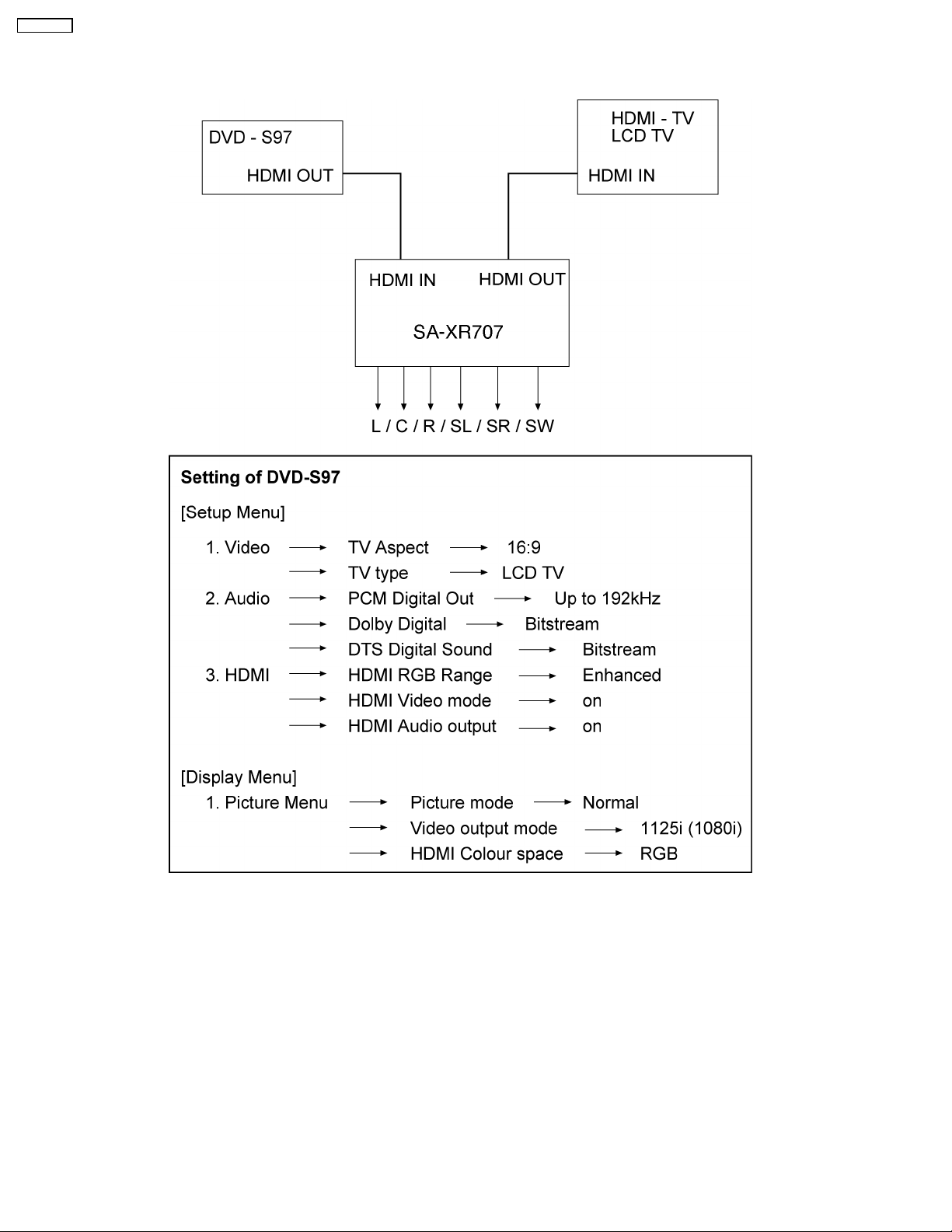
7 HDMI Checking Method
1. Connection of HDMI system
2. Check of HDMI Sound
a. Using the [DVD AUDIO TEST DISC V-612] and DVD-VIDEO disc with Dolby Digital signal.
b. [DVD AUDIO TEST DISC V-612] - Track No. 92 (96kHz, 5.1ch). Track No. 40 (Zero) Check the Level and Noise, output from
L / C / R / SL / SR / SW / speaker or pin.
c. [DVD AUDIO TEST DISC V-612] - Track No. 7 (192kHz, 2ch)
if this source can be reproduced, it is OK.
3. Check of HDMI Picture
a. The picture quality of TV is checked by watching that using [DVD TEST DISK S-20] or DVD disc with the colour bar signal.
b. [DVD TEST DISK S-20] - Track No. 2 (Flag of the rising sun)
[Colour bar disc] - Colour bar signal.
c. Make on DVD Setup Picture
Comfirmed that there are neither distortion nor a noise on the screen.
• If it is a picture quality equal when DVD was connected directly to TV, it is OK
24
SA-XR707P
1. Connect directly DVD player to TV.
2. Connect DVD player to set then connect it to TV.
3. Do the comparison for (1) and (2) if same, it is OK.
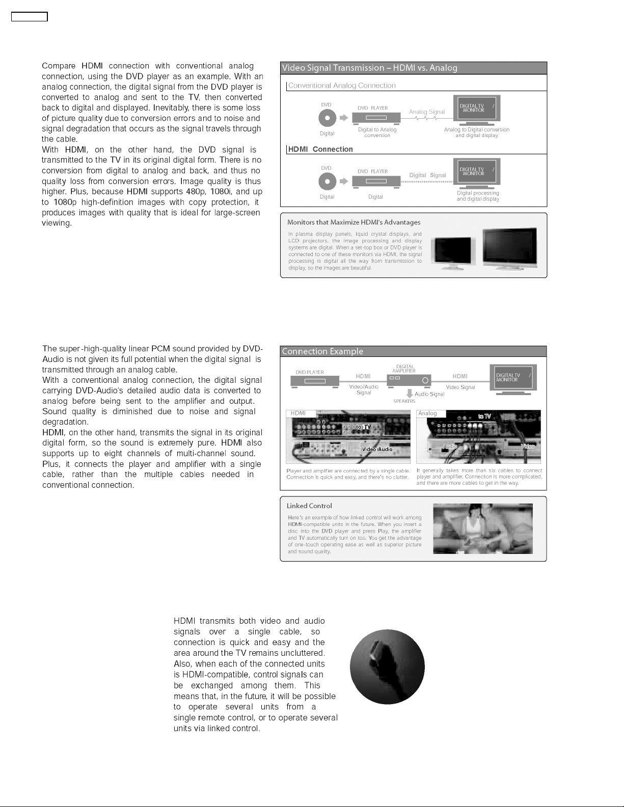
7.1. What is HDMI?
The High-Definition Multimedia Interface (HDMI) is rapidly emerging as the connection standard for HDTV. Developed by Sony,
Hitachi, Thomson (RCA), Philips , Matsushita (Panasonic), Toshiba and Silicon Image as the digital interface standard for the
consumer electronics market, HDMI combines high-definitio n video and multi-channel audio in a single digital interface to provide
crystal-clear digital quality over a single cable. One cable for audio and video dramatically simplifies home theater system
installation and eliminates the cable mess behind entertainment system components. HDMI offers significant advantages over
analog A/V connections, including the ability to transmit uncompressed digital video and audio content. Hollywood studios and
cable and satellite operators support HDMI.
HDMI is based on Silicon Image´s TMDS
®
technology and is fully backward compatible with PCs and displays incorporating the
Digital Visual Interface (DVI) standard, which was also pioneered by Silicon Image. Because it was designed specifically for
consumer electronics applications, HDMI offers additional consumer enhancements. Content comes in a variety of sizes,
resolutions and formats, and HDMI systems will automatically configure to display content in the most effective format. In addition,
with a point and click, HDMI´s integrated remote capability automatically configures the home theater system on demand, turning
on or off the components necessary to view a DVD, listen to a CD or watch cable or satellite TV.
25
SA-XR707P
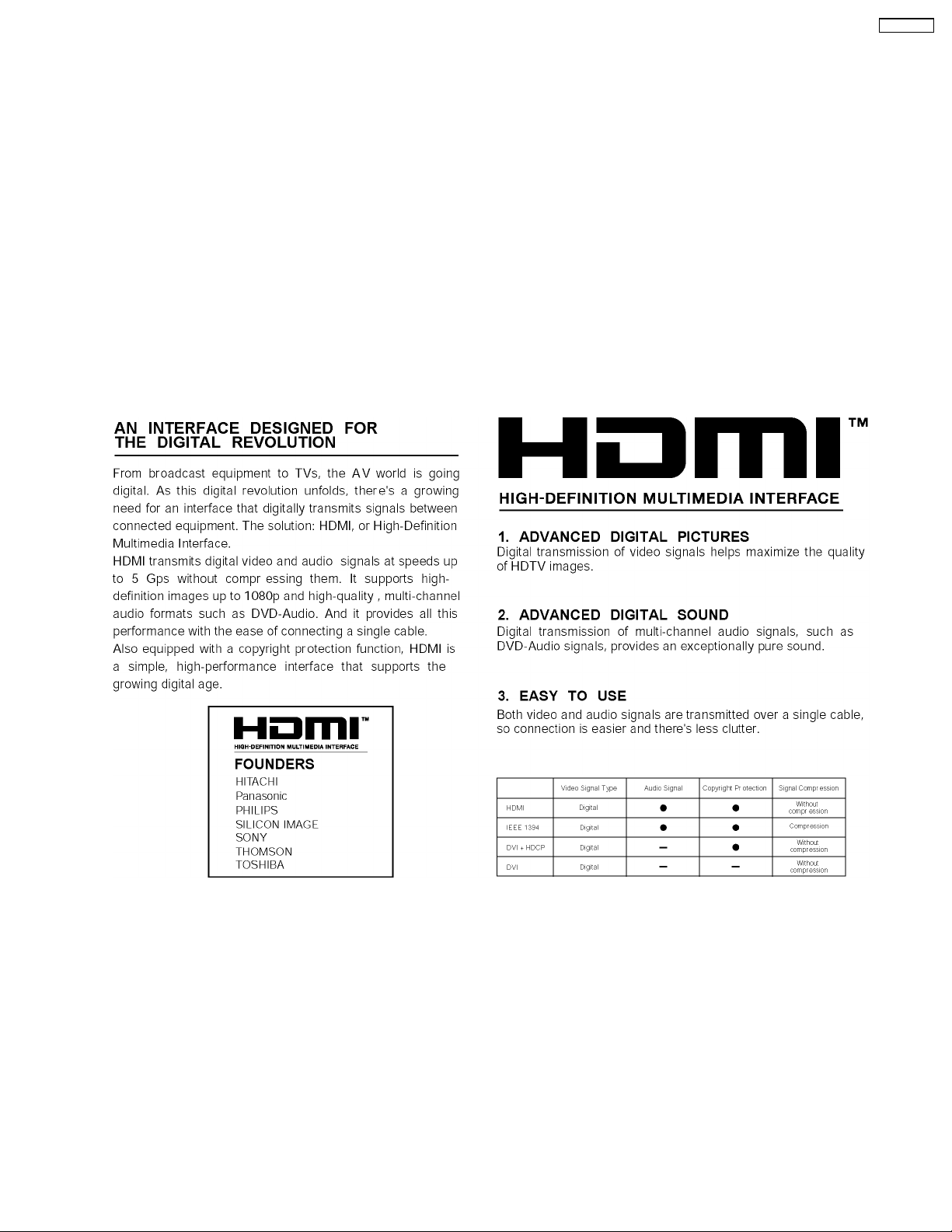
7.2. Advanced Digital Pictures
7.3. Advanced Digital Sound
7.4. Easy to Use
26
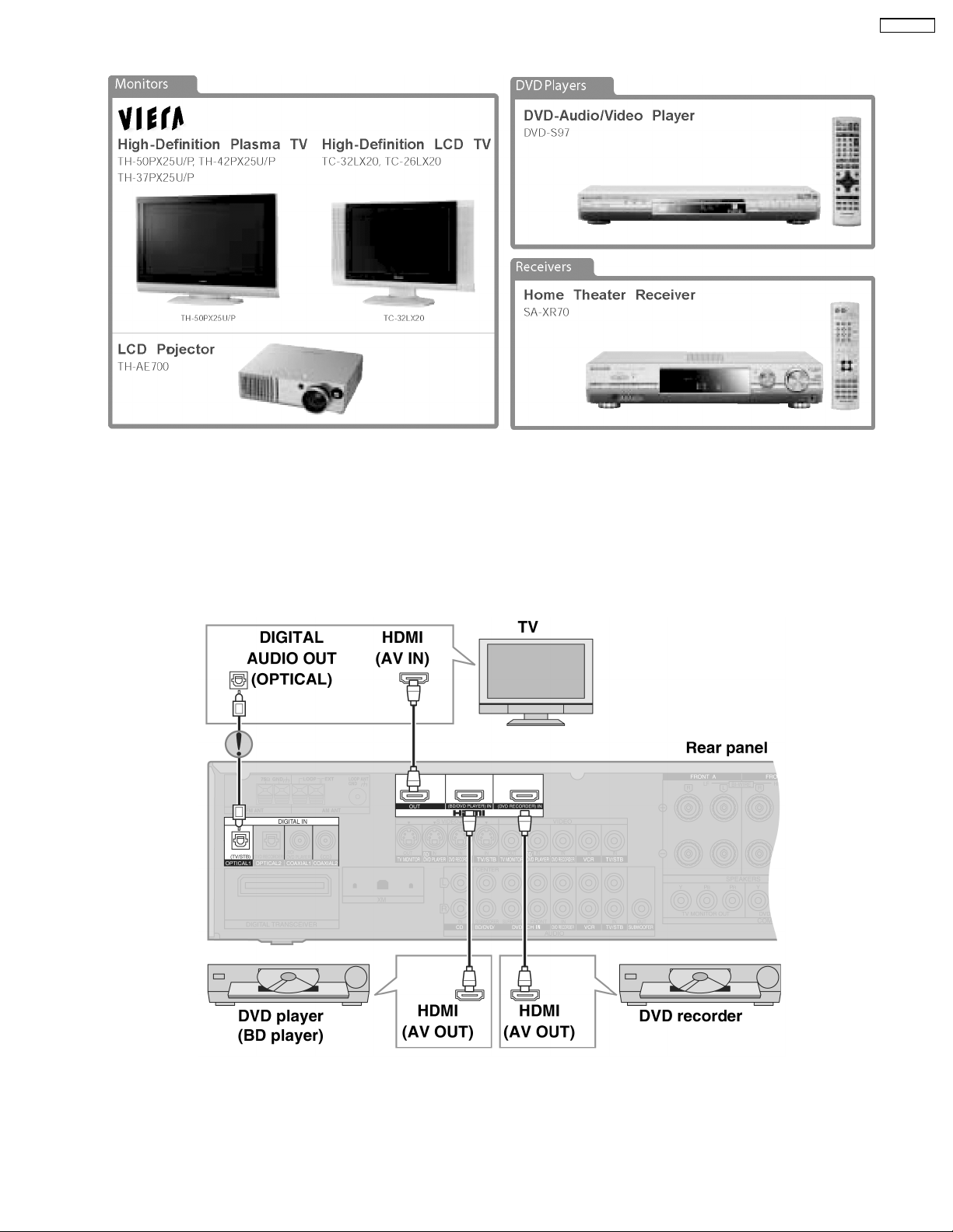
7.5. HDMI Compatible Products
7.6. Main features and benefits
SA-XR707P
• All digital provides the highest quality —
HDMI is the only interface in consumer electronics that can carry both uncompressed high-definition video and uncompressed
multi-channel audio in all HD formats, including 720p, 1080i and even upcoming 1080p .
• A single cable connection means no more cable mess —
Since HDMI carries all digital video and audio channels, there is only one cable to connect any HDMI-enabled source device
to a display .
7.7. Other features and benefits
• Automatic format adjustment matches content to preferred viewing format —
HDMI systems can automatically configure to display content in its most effective format. If cable TV content jumps from 16:9
format to standard 4:3, an HDMI-enabled TV will automatically adjust to match the ideal format.
27

SA-XR707P
• Integrated remote provides simple control of your system —
HDMI allows CE manufacturers to build intelligence into their devices so that one remote click can configure your entire HDMIenabled system to turn certain components on or off depending on the specific components that are required.
• PC Compatibility enables viewing of your PC data on your HDTV —
HDMI-enabled devices are backwards compatible with the broad array of DVI-based PCs so that you can display gaming or
entertainment content on your HDTV.
28
SA-XR707P
8 Assembling and Disassembling
8.1. Caution
“ATTENTION SERVICER”
Some chassis components may be have sharp edges. Be careful when disassembling and servicing.
1. This section describes procedures for checking the operation of the major printed circuit boards and replacing the main
components.
2. For reassembly after operation checks or replacement, reverse the respective procedures.
Special reassembly procedures are described only when required.
3. Select items from the following index when checks or replacement are required.
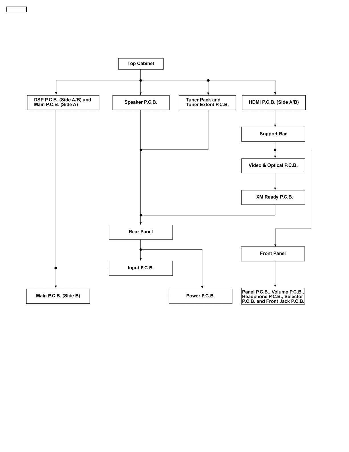
Below is the list of disassembly sections
• Disassembly of Top Cabinet
• Disassembly and Checking the DSP P.C.B. (Side A/B) and Main P.C.B. (Side A)
• Disassembly of Tuner Pack and Tuner Extent P.C.B.
• Disassembly and Checking of Speak er P.C.B.
• Disassembly and Checking of HDMI P.C.B. (Side A/B)
• Disassembly Support Bar
• Disassembly and Checking of Video & Optical P.C.B.
• Disassembly of XM Ready P.C.B.
• Disassembly of Rear Panel
• Disassembly and Checking of Input P.C.B.
• Disassembly and Checking of Main P.C.B. (Side B)
• Disassembly and Checking of Power P.C.B.
• Disassembly of Front Panel
• Disassembly and Checking of Panel P.C.B., Volume P.C.B., Headphone P.C.B., Selector P.C.B. and Front Jack P.C.B.
• Insert wire & Wire dressing
29
SA-XR707P
8.2. Disassembly flow chart
The following chart is the procedure for disassembling the casing and inside parts for internal inspection when carrying out the
servicing.
To assemble the unit, reverse the steps shown in the chart below.
30
 Loading...