

Panasonic SAXR-58-E, SAXR-58-EG Service manual
AV Control Receiver
SA-XR58E
SA-XR58EG
Colour
(S)... Silver Type
(K)... Black Type
ORDER NO. MD0606214CE
Specification
n AMPLIFIER SECTION
Power output (at AC 230 to 240 V)
DIN 1 kHz (T.H.D. 1 %) 2 x 100 W (6 Ω)
20 Hz to 20 kHz continuous power
output both channel driven
Total harmonic distortion
rated power at 20 Hz to 20 kHz 0.09 % (6 Ω)
Power bandwidth
both channels driven, -3 dB 4Hzto88kHz
Power output each channel driven (at AC 230 to 240V)
DIN 1 kHz (T.H.D. 1 %)
Front (L/R) 100 W (6 Ω)
Center
Surround (L/R) 100 W (6 Ω)
Surround Back (L/R) 100 W (6 Ω)
Load impedance
Front (L/R)
AorB 6 Ω to 16 Ω
A and B 6 Ω to 16 Ω
BI-WIRE 6 Ω to 16 Ω
Center
Surround (L/R) 6 Ω to 16 Ω
Surround Back (L/R) 6 Ω to 16 Ω
Frequency response
CD, DVD, DVD RECORDER, VCR,
TV/STB, AUX
DVD 6CH 4Hzto44kHz,±3dB
2x80W(6Ω)
(6 Ω,0.9%)
100 W (6 Ω)
6 Ω to 16 Ω
4Hzto88kHz,±3dB
Input sensitivity and impedance
CD, DVD/DVD 6CH, DVD RECORDER,
VCR, TV/STB, AUX
S/N at rated power (6 ΩΩΩΩ)
CD, TV/STB, DVD, DVD RECORDER
(Digital Input)
Tone controls
BASS 50 Hz, +10 dB to -10
TREBLE 20 kHz, +10 dB to -10
Channel balance (250 Hz-6.3 kHz)
Channel separation 55 dB
Subwoofer frequency response (-6 dB) 7 Hz to 200 Hz
Digital input
(Optical) 2
(Coaxial)
HDMI (version 1.2a)
(Input) 1
(Output) 1
n FM TUNER SECTION
Frequency range 87.50 MHz to 108.00
Sensitivity
S/N 30 dB 1.5 µV / 75Ω
S/N 26 dB 1.3 µV / 75Ω
S/N 20 dB 1.2 µV / 75Ω
200 mV / 22 kΩ
90 dB
(IHF, A: 103 dB)
dB
dB
±1 dB
MHz
2
© 2006 Matsushita Electric Industrial Co. Ltd.. All
rights reserved. Unauthorized copying and
distribution is a violation of law.
SA-XR58E / SA-XR58EG
IHF usable sensitivity (IHF,58) 1.5 µV / 75Ω
IHF 46 dB stereo quieting sensitivity 22 µV / 75Ω
Total harmonic distortion
MONO 0.2%
STEREO 0.3%
S/N
MONO 60 dB
STEREO 58 dB
Frequency response 20 Hz to 15 kHz,
+1 dB, -2 dB
Alternate channel selectivity
Capture ratio 1.5 dB
Image rejection at 98 MHz
IF rejection at 98 MHz 70 dB
Spurious respone rejection at 98 MHz 70 dB
AM suppression 50 dB
Stereo separation
Carrier leak 19 kHz, -30 dB
Channel balance (250 Hz-6.3 kHz)
Limiting point 1.2 µV
Bandwidth
IF amplifier 180 kHz
FM demodulator 1000 kHz
Antenna terminal 75 Ω (unbalanced)
±400 kHz, 65 dB
40 dB
40 dB
38 kHz, -50 dB
±1.5 dB
Selectivity (at 999 kHz) 55 dB
IF rejection (at 999 kHz) 50 dB
n VIDEO SECTION
Output voltage at 1 V input (unbalanced) 1 ± 0.1 Vp-p
Maximum input voltage 1.5 Vp-p
Input/output impedance 75 Ω (unbalanced)
S-Video
Input DVD, DVD Recorder,
TV/STB
Output
Component Video
Input
Output TV MONITOR
n GENERAL
Power supply
Power consumption 140 W
Dimensions (W × H × D) 430 mm × 107.5 mm ×
Mass
Power consumption in standby mode:
Power consumption in HDMI off mode:
TV MONITOR
DVD Recorder,
TV/STB
AC 230 to 240 V, 50
Hz
390 mm
4.7 kg
0.9 W
0.35 W
n AM TUNER SECTION
Frequency range
Sensitivity 20 µV, 330 µV/m
522 kHz to 1611 kHz
(9 kHz steps)
530 kHz to 1620 kHz
(10 kHz steps)
Notes:
1. Specifications are subject to change without notice.
2. Mass and dimensions are approximate.
3. Total harmonic distortion is measured by the digital spectrum
analyzer.
CONTENTS
Page Page
1 Safety Precautions
1.1. GENERAL GUIDELINES
1.2. Before Repair and Adjustment
1.3. Protection Circuitry
2 Prevention of Electro Static Discharge (ESD) to
Electrostatically Sensitive (ES) Devices
3 Handling the Lead free Solder
3.1. General description about Lead Free Solder (PbF)
4 Accessories
5 Operating Instructions Procedures
5.1. Remote Control Operation
5.2. Main Unit Operation
5.3. Main Unit connections (SA-XR58)
6 Self Diagnosis Display Function
4
4
5
5
6
7
7
8
9
9
10
11
6.1. Automatically Displayed Error Codes
6.2. Display Details
6.3. Returning to Normal Display
6.4. Overload/Shutdown Detection intenal Condition
6.5. Overload/Thermal Detection Display
6.6. Activating Self Diagnosis Function (Servicing Mode)
6.7. Analog 6.1 CH Output Check Method
6.8. Returning to Normal Display
6.9. Activating Self Diagnosis Function (Doctor Mode)
7 HDMI Checking Method
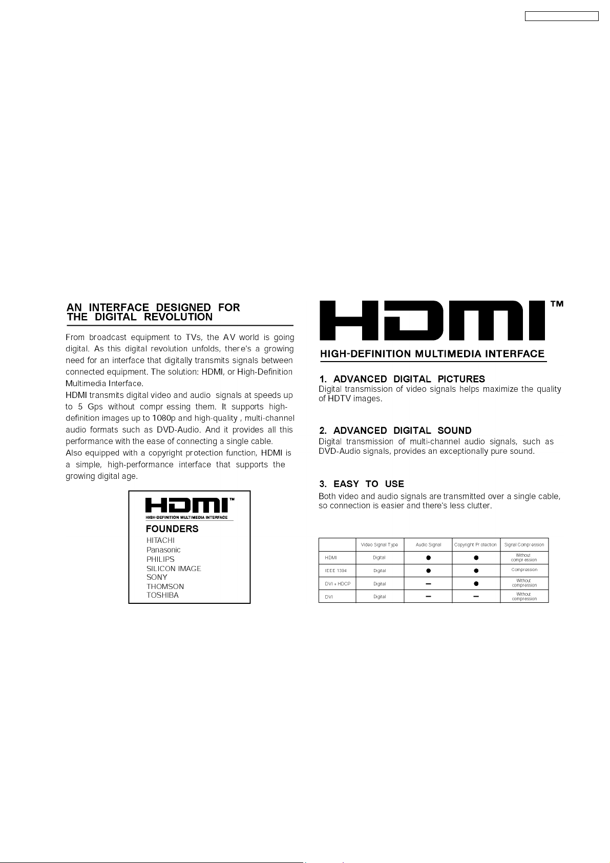
7.1. What is HDMI?
7.2. Advanced Digital Pictures
19
19
19
19
19
19
19
20
20
20
22
23
24
2
SA-XR58E / SA-XR58EG
7.3. Advanced Digital Sound 24
7.4. Easy to Use
7.5. HDMI Compatible Products
7.6. Main features and benefits
7.7. Other features and benefits
8 Assembling and Disassembling
8.1. Caution
8.2. Disassembly flow chart
8.3. Main Parts Location Diagram
8.4. Disassembly of Top Cabinet
8.5. Disassembly and Checking the DSP P.C.B. (Side A/B)
and Main P.C.B. (Side A)
8.6. Disassembly of Tuner Pack and Tuner Extent P.C.B.
8.7. Disassembly and Checking of Speaker P.C.B.
8.8. Disassembly and Checking of HDMI P.C.B. (Side A/B)
8.9. Disassembly Support Bar
8.10. Disassembly and Checking of Video & Optical P.C.B.
8.11. Disassembly of Rear Panel
8.12. Disassembly and Checking of Input P.C.B.
8.13. Disassembly and Checking of Main P.C.B. (Side B)
8.14. Disassembly and Checking of Power P.C.B.
8.15. Disassembly of Front Panel
8.16. Disassembly and Checking of Panel P.C.B., Volume
P.C.B. and Headphone P.C.B.
8.17. Insert wire & Wire dressing
9 Voltage Measurement & Waveform Chart
9.1. Voltage Measurement
9.2. Waveform Chart
10 Wiring Connection Diagram
11 Block Diagram
12 Notes of Schematic Diagram
13 Schematic Diagram
24
25
25
25
27
27
28
29
30
13.1. DSP CIRCUIT
13.2. MAIN (DIG1) CIRCUIT
13.3. MAIN (DIG2) CIRCUIT
13.4. MAIN (DIG3) CIRCUIT
13.5. INPUT CIRCUIT
13.6. PANEL CIRCUIT
13.7. SPEAKER CIRCUIT
13.8. POWER CIRCUIT
13.9. HDMI CIRCUIT
13.10. VIDEO & OPTICAL CIRCUIT
30
31
32
32
34
34
35
36
36
37
38
13.11. TUNER EXTENT CIRCUIT, HEADPHONE CIRCUIT
AND VOLUME CIRCUIT
14 Printed Circuit Board Diagrams
14.1. DSP P.C.B
14.2. MAIN P.C.B
14.3. INPUT P.C.B
14.4. TUNER EXTENT P.C.B, SPEAKER P.C.B, HEADPHONE
P.C.B and VOLUME P.C.B
14.5. PANEL P.C.B and VIDEO & OPTICAL P.C.B
14.6. POWER P.C.B
14.7. HDMI P.C.B
15 Illustration of IC's, Transistor s and Diodes
39
16 Terminal Function of IC's
40
41
41
55
57
59
16.1. IC6801 (C2BBYY000302) IC MICROPROCESSOR
16.2. IC6901 (C2CBYY000323) IC SUB MICRO-P
17 Exploded Views
17.1. Cabinet Parts Location
17.2. Packaging
18 Replacement Parts List
67
69
69
72
76
80
82
84
85
86
89
93
95
97
97
98
100
101
102
103
104
107
108
108
108
111
111
113
115
3
SA-XR58E / SA-XR58EG
1 Safety Precautions
1.1. GENERAL GUIDELINES
1. When servicing, observe the original lead dress. If a short circuit is found, replace all parts which have been overheated or
damaged by the short circuit.
2. After servicing, ensure that all the protective devices such as insulation barriers, insulation papers shields are properly installed.
3. After servicing, check for leakage current checks to prevent from being exposed to shock hazards.
1.1.1. LEAKAGE CURRENT COLD CHECK
1. Unplug the AC cord and connect a jumper between the two prongs on the plug.
2. Using an ohmmeter measure the resistance value, between the jumpered AC plug and each exposed metallic cabinet part on
the equipment such as screwheads, connectors, control shafts, etc. When the expose d metallic part has a return path to the
chassis, the reading should be between 1MΩ and 5.2Ω.
When the exposed metal does not have a return path to the chassis, the reading must be
.
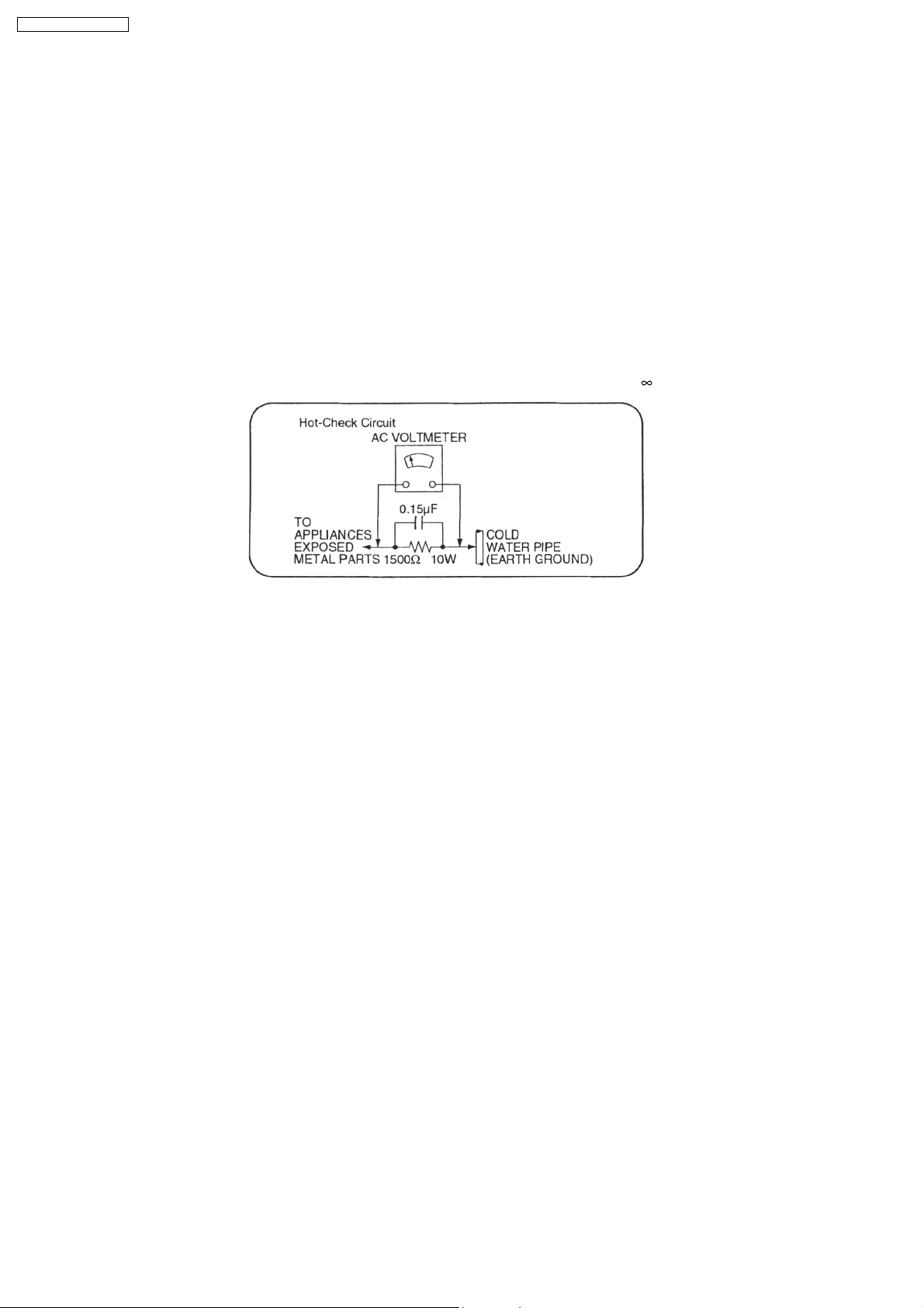
Figure. 1
1.1.2. LEAKAGE CURRENT HOT CHECK (See Figure 1.)
1. Plug the AC cord directly into the AC outlet. Do not use an isolation transformer for this check.
2. Connect a 1.5kΩ, 10 watts resistor, in parallel with a 0.15µF capacitors, between each exposed metallic part on the set and a
good earth ground such as a water pipe, as shown in Figure 1.
3. Use an AC voltmeter, with 1000 ohms/volt or more sensitivity, to measure the potential across the resistor.
4. Check each exposed metallic part, and measure the voltage at each point.
5. Reverse the AC plug in the AC outlet and repeat each of the above measurements.
6. The potential at any point should not exceed 0.75 volts RMS. A leakage current tester (Simpson Model 229 or equivalent) may
be used to make the hot checks, leakage current must not exceed 1/2 milliamp. should the measurement is outside of the limits
specified, there is a possibility of a shock hazard, and the equipment should be repaired and re-checked before it is returned
to the customer.
4

SA-XR58E / SA-XR58EG
1.2. Before Repair and Adjustment
Disconnect AC power, discharge Power Supply Capacitors C707, C717 and C718 through a 10Ω, 1W resistor to ground.
DO NOT SHORT-CIRCUIT DIRECTLY (with a screwdriver blade, for instance), as this may destroy solid state devices.
After repairs are completed, restore power gradually using a variac, to avoid overcurrent.
· Current consumption at AC 230 - 240V, 50 Hz in NO SIGNAL mode (at volume minimum) should be 200 ~ 600 mA.
1.3. Protection Circuitry
The protection circuitry may have operated if either of the following conditions are noticed:
· No sound is heard when the power is turned on.
· Sound stops during a performance.
The function of this circuitry is to prevent circuitry damage if, for example, the positive and negative speaker connection wires are
"shorted", or if speaker systems with an impedance less than the indicated rated impedance of the amplifier are used.
If this occurs, follow the procedure outlines below:
1. Turn off the power.
2. Determine the cause of the problem and correct it.
3. Turn on the power once again after one minute.
Note:
When the protection circuitry functions, the unit will not operate unless the power is first turned off and then on again.
5
SA-XR58E / SA-XR58EG
2 Prevention of Electro Static Discharge (ESD) to
Electrostatically Sensitive (ES) Devices
Some semiconductor (solid state) devices can be damaged easily by electricity. Such components commonly are called
Electrostatically Sensitive (ES) Devices. Examples of typical ES devices are integrated circuits and some field-effect transistors and
semiconductor “chip” components. The following techniques should be used to help reduce the incidence of component damage
caused by electro static discharge (ESD).
1. Immediately before handling any semiconductor component or semiconductor-equiped assembly, drain off any ESD on your
body by touchin g a known earth ground. Alternatively, obtain and wear a commercially available discharging ESD wrist strap,
which should be removed for potential shock reasons prior to applying power to the unit under test.
2. After removing an electrical assembly equiped with ES devices, place the assembly on a conductive surface such as aluminium
foil, to prevent electrostatic charge build up or exposure of the assembly.
3. Use only a grounded-tip soldering iron to solder or unsolder ES devices.
4. Use only an anti-static solder removal device. Some solder removal devices not classified as “anti-static (ESD protected)” can
generate electrical charge to damage ES devices.
5. Do not use freon-propelled chemicals. These can generate electrical charges sufficient to damage ES devices.
6. Do not remove a replacement ES device from its protective package until immediately before you are ready to install it. (Most
replacement ES devices are packaged with leads electrically shorted together by conductive foam, aluminium foil or
comparable conductive material).
7. Immediately before removing the protective material from the leads of a replacement ES device, touch the protective material
to the chassis or circuit assembly into which the device will be installed.
Caution
Be sure no power is applied to the chassis or circuit, and observe all other safety precautions.
8. Minimize bodily motions when handling unpackaged replacement ES devices. (Otherwise harmless motion such as the
brushing together of your clothes fabric or the lifting of your foot from a carpeted floor can generate static electricity (ESD)
sufficient to damage an ES device).
6

SA-XR58E / SA-XR58EG
3 Handling the Lead free Solder
3.1. General description about Lead Free Solder (PbF)
The lead free solder has been used in the mounting process of all electrical components on the printed circuit boards used for this
equipment in considering the globally environmental conservation.
The normal solder is the alloy of tin (Sn) and lead (Pb). On the other hand, the lead free solder is the alloy mainly consists of tin
(Sn), silver (Ag) and Copper (Cu), and the melting point of the lead free solder is higher approx.30 degrees C (86°F) more than that
of the normal solder.
Definition of PCB Lead Free Solder being used
The letter of “PbF” is printed either foil side or components side on the PCB using the lead free solder.
(See right figure)
Service caution for repair work using Lead Free Solder (PbF)
· The lead free solder has to be used when repairing the equipment for which the lead free solder is used.
(Definition: The letter of “PbF” is printed on the PCB using the lead free solder.)
· To put lead free solder, it should be well molten and mixed with the original lead free solder.
· Remove the remaining lead free solder on the PCB cleanly for soldering of the new IC.
· Since the melting point of the lead free solder is higher than that of the normal lead solder, it takes the longer time to melt
the lead free solder.
· Use the soldering iron (more than 70W) equipped with the temperature control after setting the temperature at 350±30
degrees C (662±86°F).
Recommended Lead Free Solder (Service Parts Route.)
· The following 3 types of lead free solder are available through the service parts route.
RFKZ03D01K-----------(0.3mm 100g Reel)
RFKZ06D01K-----------(0.6mm 100g Reel)
RFKZ10D01K-----------(1.0mm 100g Reel)
Note
* Ingredient: Tin (Sn), 96.5%, Silver (Ag) 3.0%, Copper (Cu) 0.5%, Cobalt (Co) / Germanium (Ge) 0.1 to 0.3%
7
SA-XR58E / SA-XR58EG
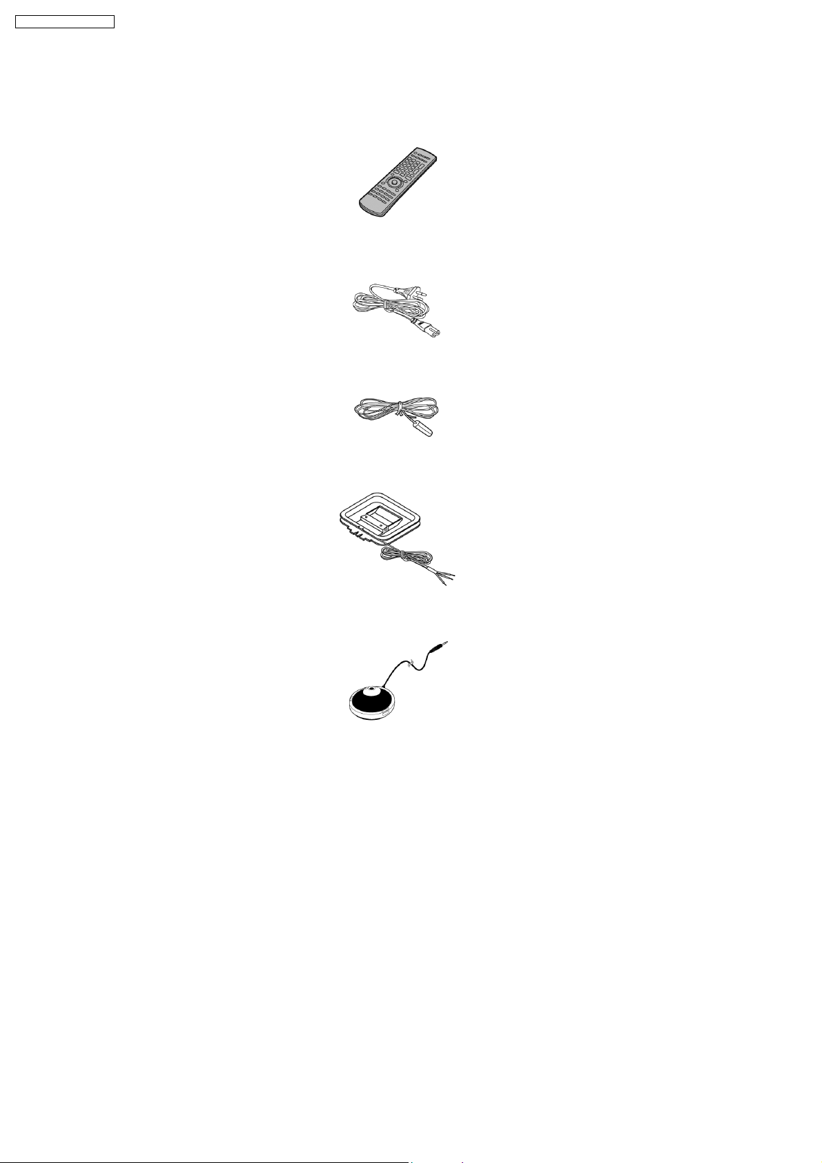
4 Accessories
Note : Refer to Packing Materials & Accessories Parts List (Section 18) for the part number.
Remote Control
AC Power Cord
FM Antenna
AM Loop Antenna
Calibration Mic
8
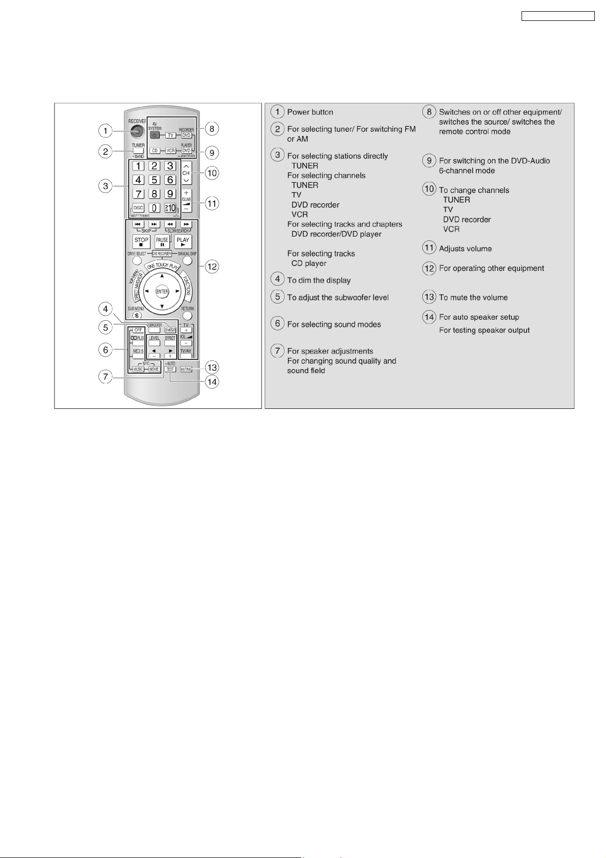
5 Operating Instructions Procedures
5.1. Remote Control Operation
SA-XR58E / SA-XR58EG
9
SA-XR58E / SA-XR58EG
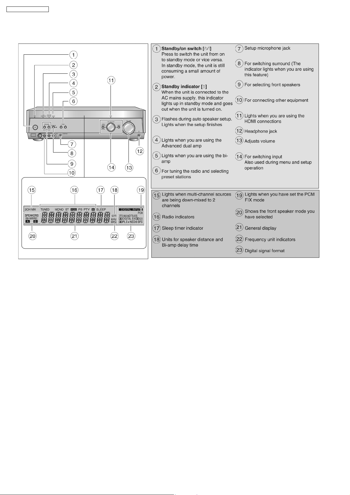
5.2. Main Unit Operation
10
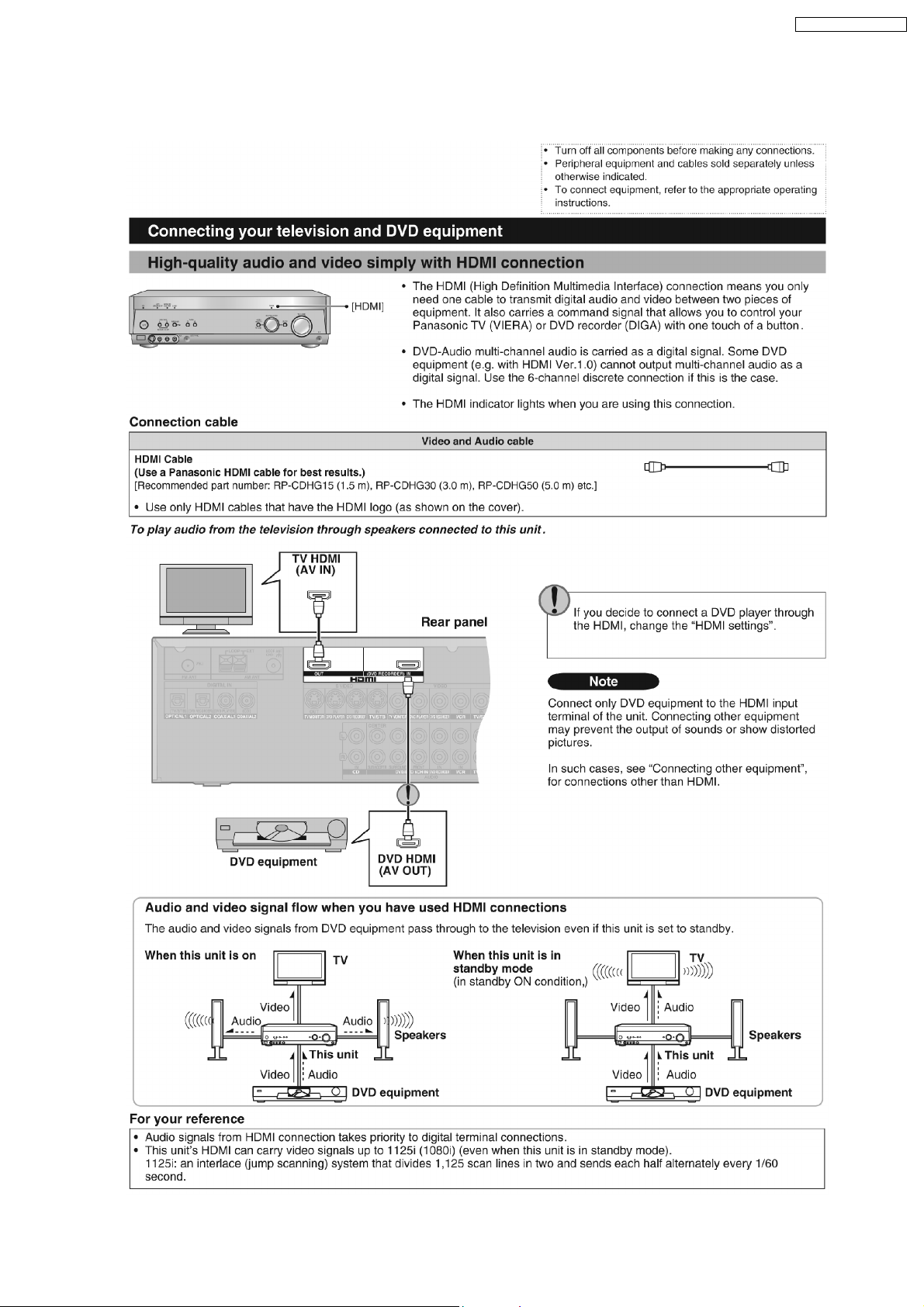
5.3. Main Unit connections (SA-XR58)
5.3.1. HDMI connection
SA-XR58E / SA-XR58EG
11
SA-XR58E / SA-XR58EG
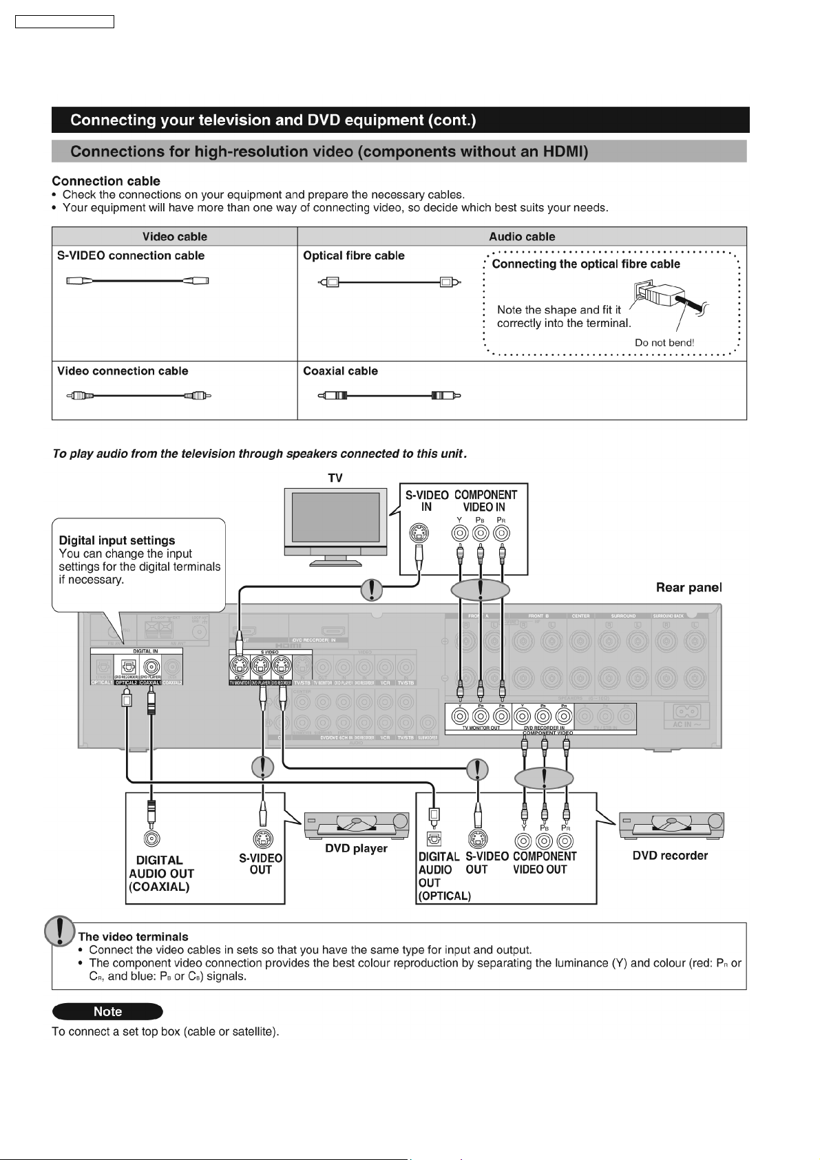
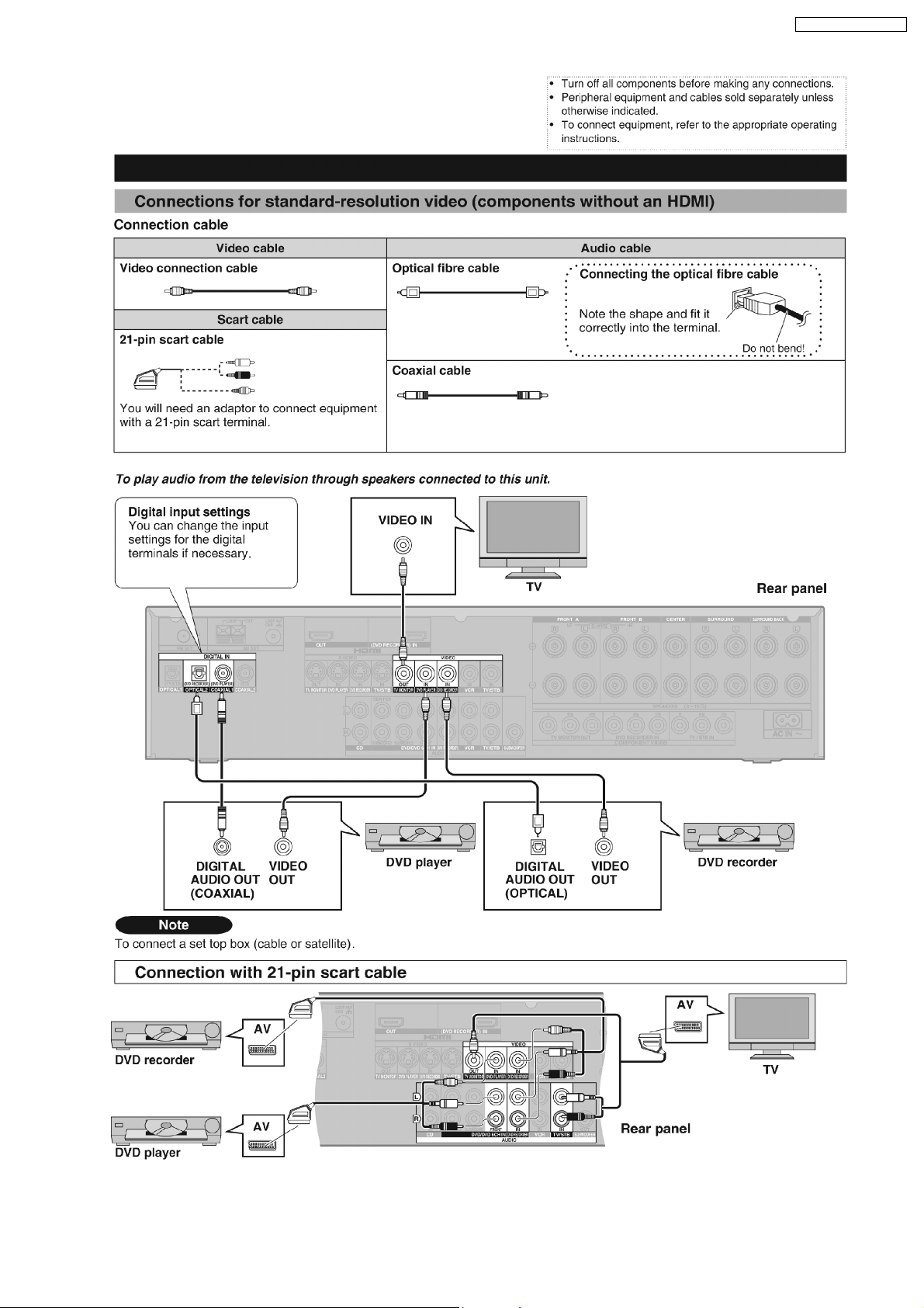
5.3.2. Video connection
12
SA-XR58E / SA-XR58EG
13
SA-XR58E / SA-XR58EG
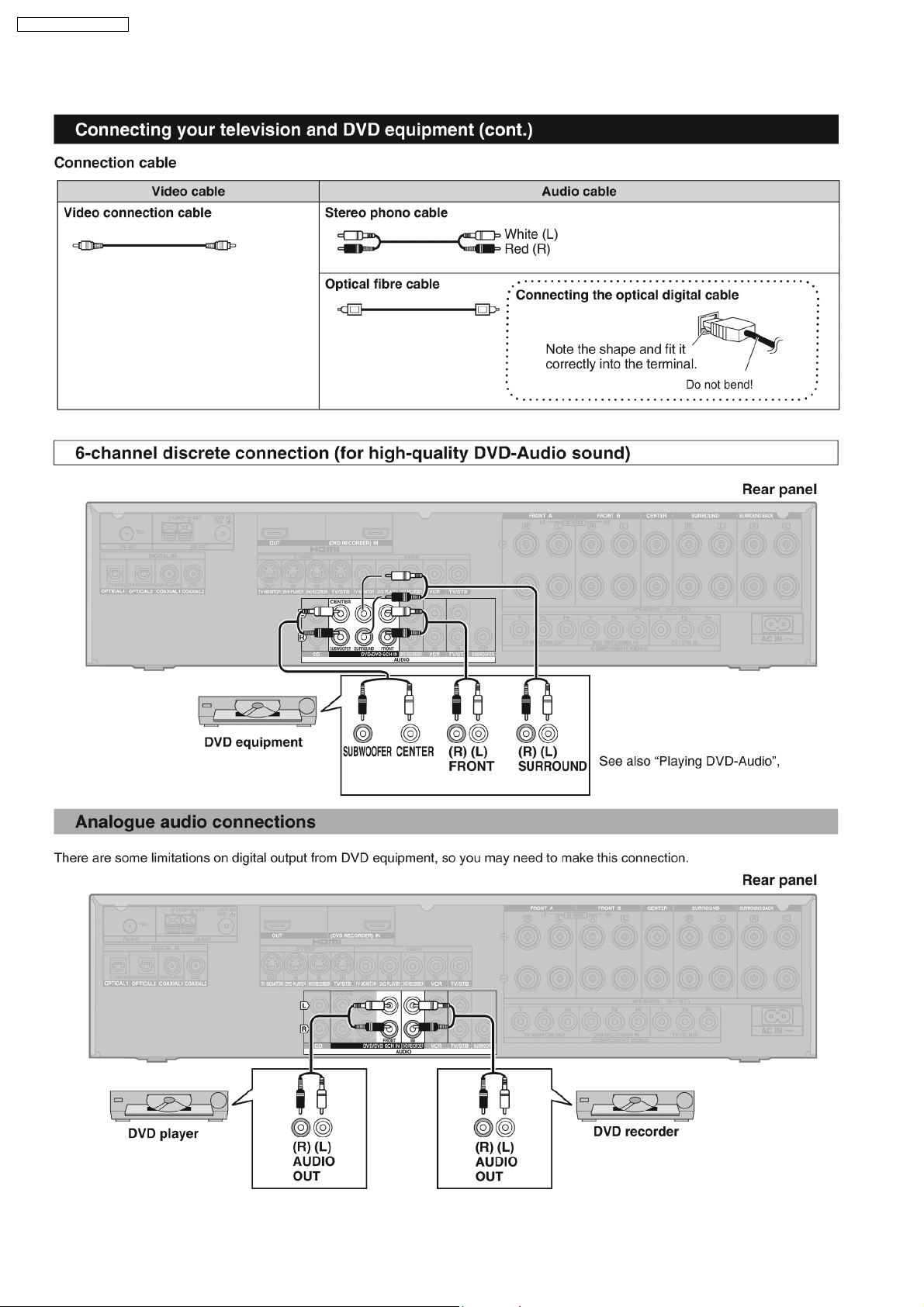
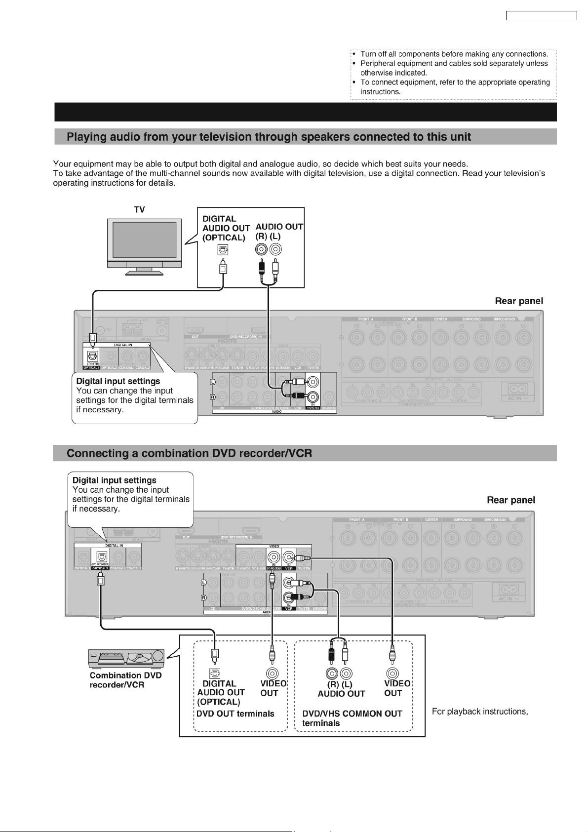
5.3.3. Audio connection
14
SA-XR58E / SA-XR58EG
15
SA-XR58E / SA-XR58EG
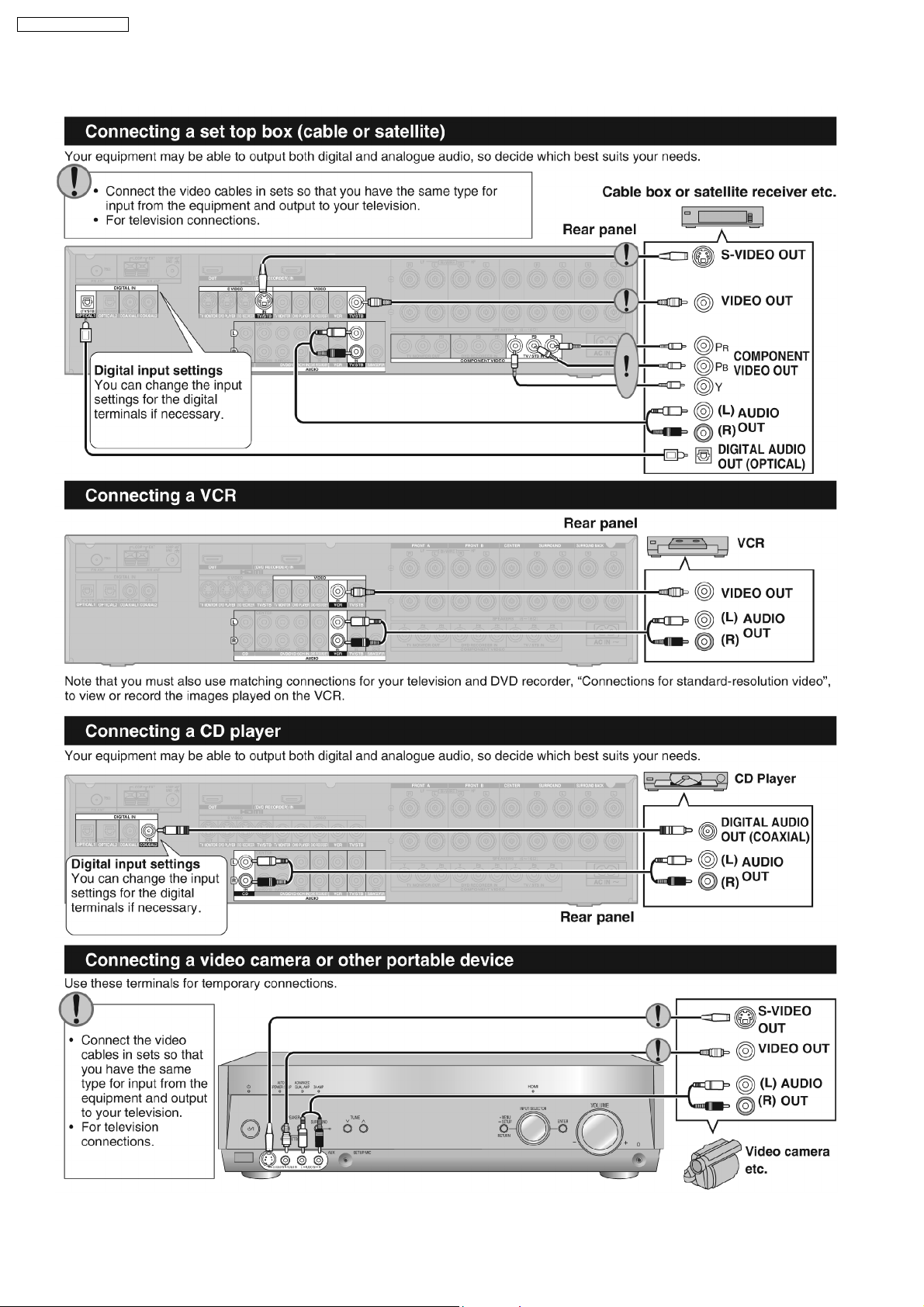
5.3.4. Connection with other equipments
16
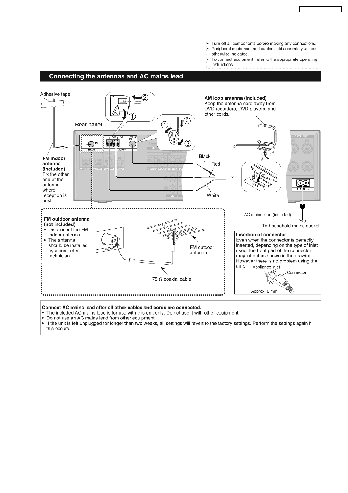
5.3.5. Tuner Antenna Connection / Power
SA-XR58E / SA-XR58EG
17
SA-XR58E / SA-XR58EG
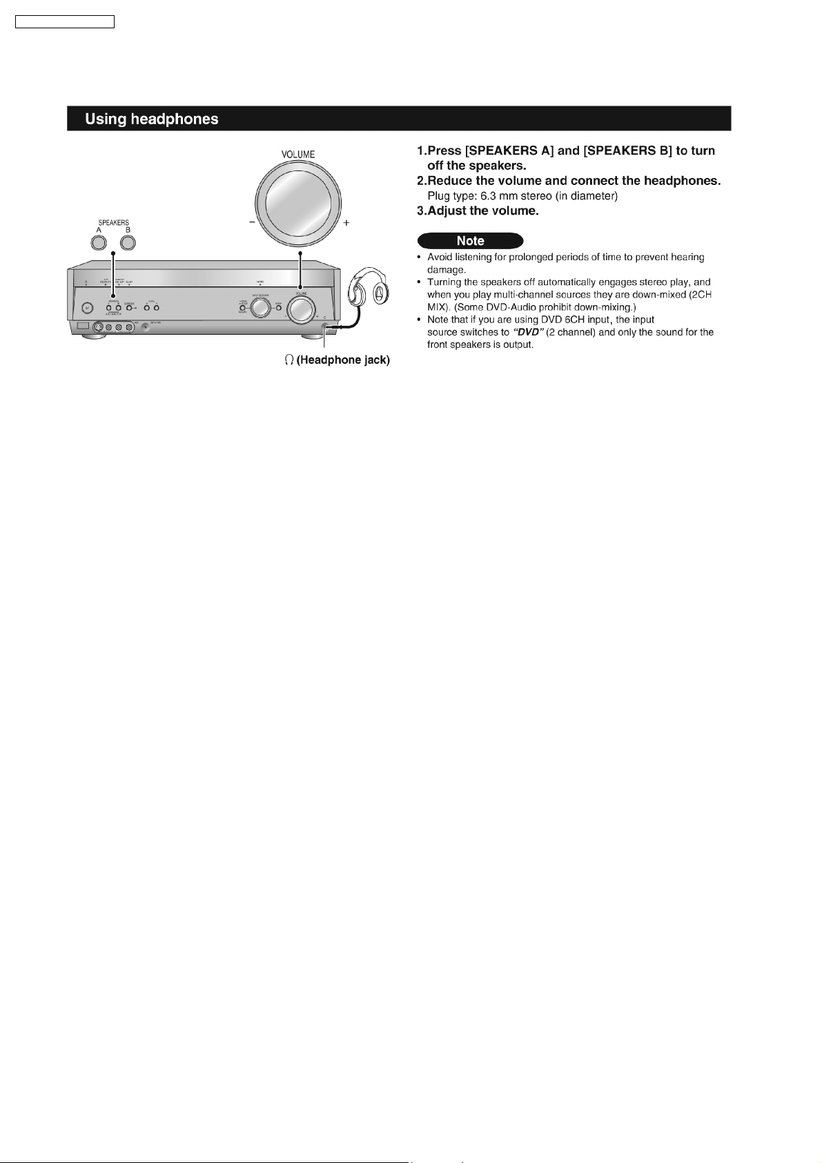
5.3.6. Headphone connection
18
SA-XR58E / SA-XR58EG
6 Self Diagnosis Display Function
This unit is equipped with the self diagnosis display function, which alarms faulty operation with error code. Use this function during
servicing.
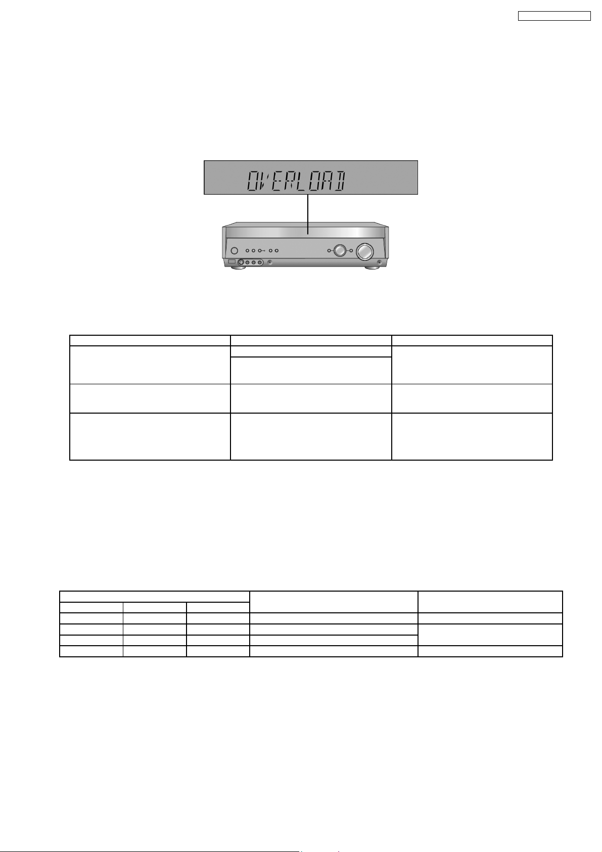
6.1. Automatically Displayed Error Codes
An error code automatically appears on the display (LCD) when faulty operation is detected. Refer to Fig. 6.1.
Fig. 6.1
6.2. Display Details
Refer to the following table.
LCD display Symptom Cause and Remedy
OVERLOAD Speaker short, amplifier failure Speaker short and failure in power
Humidity protection activated
F70 Communication error between sub micro-
processor and its peripheral LSI
F76 When the power is turned on, the unit
power automatically turns off; the power
cannot be turned on.
amplifier, pre-amplifier circuits. Check for
faulty parts and replace with new parts if
necessary.
Failure sub-micro processor and its
peripherals LSI. Check for faulty parts and
replace with new parts if necessary.
Failure in the power circuit system of the
unit. This may happen when the direct
current electricity is supplied to speaker
terminals. Check for the above and replace
with new parts if necessary.
6.3. Returning to Normal Display
Press the [POWER] button on the unit to exit the function. The power is turned off.
6.4. Overload/Shutdown Detection intenal Condition
It detects OVERLOAD, POWER MALFUNCTION with [THRM_DET], [SHORT_DET ] and [DC_DET] input port. It detects the
following condition depending on the input of the port as below table.
(H: DC ± 5V / L: DC ± 0V)
PROT Detection of malfunction Display and operation
SHORT_DET THRM_DET DC_DET
H L H Normal ----L L H Speaker Short, Malfunction of Amplifier [OVERLOAD] / POWER OFF
L H H Detection of THERMAL PROTECTION
- - L Detection of POWER MALFUNCTION [ _ _ _ F76 _ _ _ ] / POWER OFF
6.5. Overload/Thermal Detection Display
When overload is detected, automatic POWER OFF will occur. But if any key on the remote control other than the [POWER] key
is pressed before that (including the [HELP] key), the scroll display will show [SWITCH_OFF_POWER]. Then, 1 second after
display of message, [OVERLOAD] will be shown on the scroll display.
6.6. Activating Self Diagnosis Function (Servicing Mode)
This mode can be used during servicing.
1. Plug the AC adapter to the power source. Press and hold down the [ENTER] button and the [SPEAKERS A] button, and then
press the [POWER] button at the same time.
19
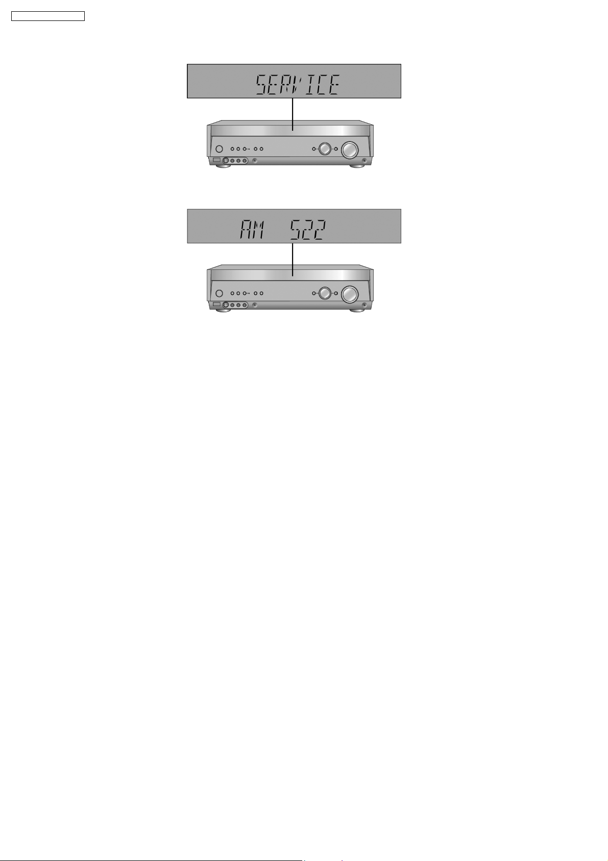
SA-XR58E / SA-XR58EG
2. The message, [SERVICE] appears on the display for three seconds, and then it will display the following. Refer to Fig. 6.2.
Fig. 6.2
3. When the [SPEAKER A] button is pressed, the current program filing number [M003 NO] appears. The *** digit indicates the
ROM checksum used for ROM collection, and if the unit is not loaded with ROM, "NO" appears.
When the [SPEAKER B] button is pressed, the sub micro computer program filing numbe r [S001 NO] appears. The *** digit
indicates the ROM checksum used for ROM collection, and if the unit is not loaded with ROM, "NO" appears.
6.7. Analog 6.1 CH Output Check Method
When the [SUBWOOFER] button on the remote controller, the function is switched to "Input Inspection Mode", which output analog
input signals at L channel of VCR analog input to all channels.
6.8. Returning to Normal Display
Press the [POWER] button on the unit to exit the function. The power is turned off.
6.9. Activating Self Diagnosis Function (Doctor Mode)
This mode can be used during servicing.
1. Plug the AC adapter to the power source. Press and hold down the [MENU-SETUP, RETURN] button and the [SPEAKERS A]
button, and then press the [POWER] button at the same time.
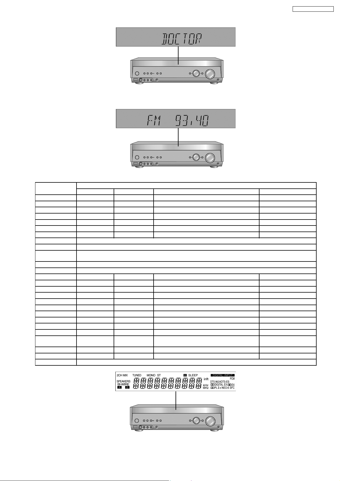
2. Initialize all the setting and set the frequency “93.40MHz” to Tuner.
The message, “_DOCTOR_” appea rs on the display for three seconds, and then it will display the following. Refer to Fig. 6.3.
20
SA-XR58E / SA-XR58EG
3. Doctor mode function at some remote control codes as below table.
Remote Control Test Mode Function and settings
Selector Sound Mode other settings Vol/Tone
CH 1 TUNER STEREO Frequency : FM min -48dB/0dB
CH 2 TUNER STEREO Frequency : FM max -48dB/0dB
CH 3 TUNER STEREO FM 98.3MHz -18dB/0dB
CH 4 TUNER STEREO Frequency : AM min -48dB/0dB
CH 5 TUNER STEREO Frequency : AM max -48dB/0dB
CH 6 TUNER STEREO AM 765kHz (9kHz/step) -18dB/0dB
CH 7 TUNER STEREO AM 770kHz (10kHz/step) -18dB/0dB
CH 8 If the input selector is TUNER, auto tuning function is started to upward on current frequency.
CH 9 If the input selector is TUNER, auto tuning function is started to downward on current frequency.
CH 0 All indicators of FL are displayed. All LED are off. Refer to Fig. 6.4.
Note : After this setting, only ‘POWER’ button or ‘Checker Command’ code by the remote control can be entered.
CH UP Check Main µP software version.
CH DOWN Check µP software version and HDMI µP software version are displayed at each time pressing.
SUBWOOFER VCR (Analog) - All CH Output Mode -18dB/0dB
MUTING DVD 6CH - - -18dB/0dB
PLIIx CD STEREO Analog -18dB/0dB
NEO:6 TV/STB STEREO Analog -18dB/0dB
TV/VIDEO DVD STEREO Analog -18dB/0dB
LEVEL DVR STEREO Analog -18dB/0dB
EFFECT CD STEREO Digital (COAX 2) -48dB/0dB
OFF TV/STB STEREO Digital (OPT 1) -48dB/0dB
SFC MOVIE DVD STEREO Digital (COAX 1) -48dB/0dB
SFC MUSIC DVR STEREO Digital (OPT 2) -48dB/0dB
TEST No change SURROUND Scan the test noise output channel with 500ms
intervals
-/L CD STEREO Balance is set to leftmost (COAX 2) -18dB/0dB
+/R CD STEREO Balance is set to rightmost (COAX 2) -18dB/0dB
DIMMER If the input selector is TUNER in E2 mode. Display Mode (PS/PTY) is changed.
-18dB/0dB
Fig. 6.4
21
SA-XR58E / SA-XR58EG
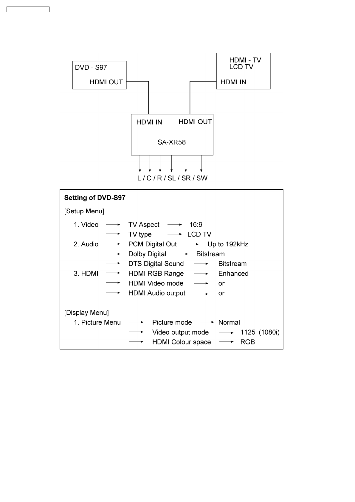
7 HDMI Checking Method
1. Connection of HDMI system
2. Check of HDMI Sound
a. Using the [DVD AUDIO TEST DISC V-612] and DVD-VIDEO disc with Dolby Digital signal.
b. [DVD AUDIO TEST DISC V-612] - Track No. 92 (96kHz, 5.1ch). Track No. 40 (Zero) Check the Level and Noise, output from
L / C / R / SL / SR / SW / speaker or pin.
c. [DVD AUDIO TEST DISC V-612] - Track No. 7 (192kHz, 2ch)
if this source can be reproduced, it is OK.
3. Check of HDMI Picture
a. The picture quality of TV is checked by watching that using [DVD TEST DISK S-20] or DVD disc with the colour bar signal.
b. [DVD TEST DISK S-20] - Track No. 2 (Flag of the rising sun)
[Colour bar disc] - Colour bar signal.
c. Make on DVD Setup Picture
Comfirmed that there are neither distortion nor a noise on the screen.
· If it is a picture quality equal when DVD was connec ted directly to TV, it is OK
22
SA-XR58E / SA-XR58EG
1. Connect directly DVD player to TV.
2. Connect DVD player to set then connect it to TV.
3. Do the comparison for (1) and (2) if same, it is OK.
7.1. What is HDMI?
The High-Definition Multimedia Interface (HDMI) is rapidly emerging as the connection standard for HDTV. Developed by Sony,
Hitachi, Thomson (RCA), Philips, Matsushita (Panasonic), Toshiba and Silicon Image as the digital interface standard for the
consumer electronics market, HDMI combines high-definitio n video and multi-channel audio in a single digital interface to provide
crystal-clear digital quality over a single cable. One cable for audio and video dramatically simplifies home theate r system
installation and eliminates the cable mess behind entertainment system components. HDMI offers significant advantages over
analog A/V connections, including the ability to transmit uncompressed digital video and audio content. Hollywood studios and
cable and satellite operators support HDMI.
HDMI is based on Silicon Image’s TMDS
®
technology and is fully backward compatible with PCs and displays incorporating the
Digital Visual Interface (DVI) standard, which was also pioneered by Silicon Image. Because it was designed specifically for
consumer electronics applications, HDMI offers additional consum er enhancements. Content comes in a variety of sizes,
resolutions and formats, and HDMI systems will automatically configure to display content in the most effective format. In addition,
with a point and click, HDMI´s integrated remote capability automatically configures the home theater system on demand, turning
on or off the components necessary to view a DVD, listen to a CD or watch cable or satellite TV.
23
SA-XR58E / SA-XR58EG
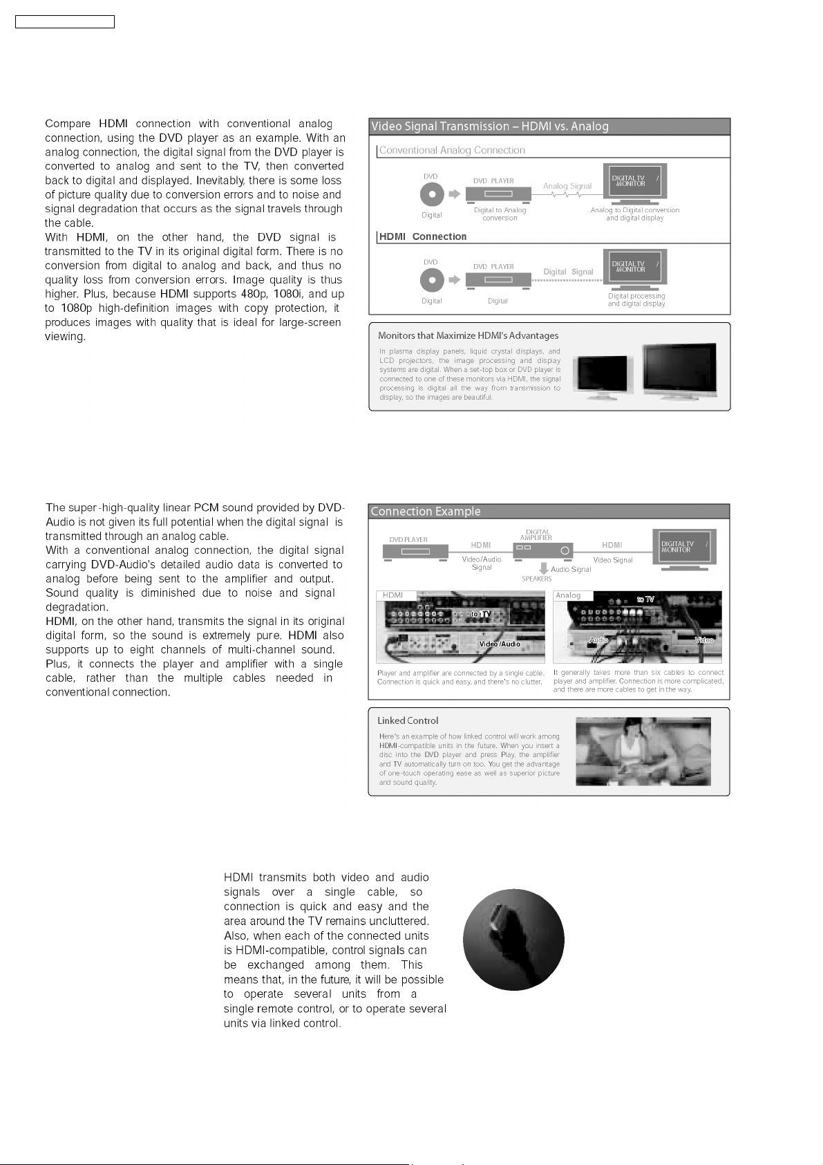
7.2. Advanced Digital Pictures
7.3. Advanced Digital Sound
7.4. Easy to Use
24
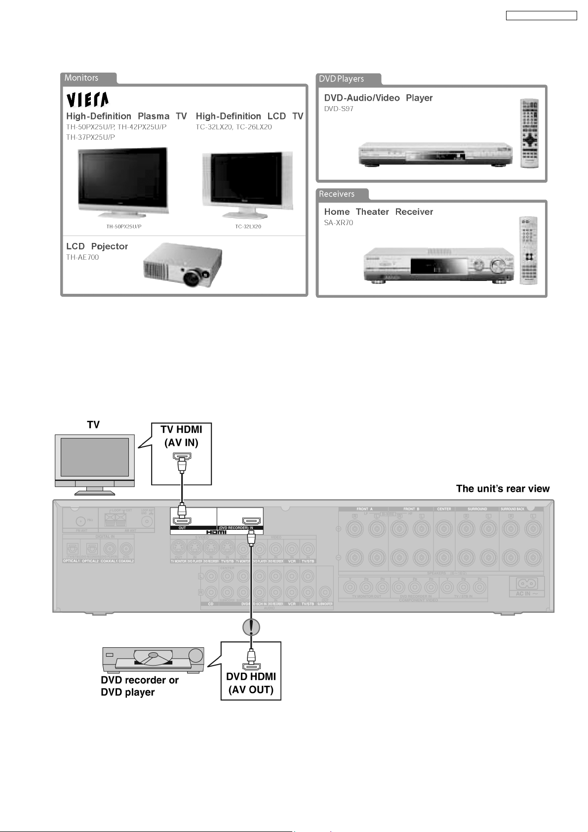
7.5. HDMI Compatible Products
SA-XR58E / SA-XR58EG
7.6. Main features and benefits
· All digital provides the highest quality —
HDMI is the only interface in consumer electronics that can carry both uncompressed high-definition video and uncompressed
multi-channel audio in all HD formats, includi ng 720p, 1080i and even upcoming 1080p.
· A single cable connection means no more cable mess —
Since HDMI carries all digital video and audio channels, there is only one cable to connect any HDMI-enabled source device
to a display.
7.7. Other features and benefits
· Automatic format adjustment matches content to preferred viewing format —
HDMI systems can automatically configure to display content in its most effective format. If cable TV content jumps from 16:9
format to standard 4:3, an HDMI-enable d TV will automatically adjust to match the ideal format.
25

SA-XR58E / SA-XR58EG
· Integrated remote provides simple control of your system —
HDMI allows CE manufacturers to build intelligence into their devices so that one remote click can configure your entire HDMIenabled system to turn certain components on or off depending on the specific components that are required.
· PC Compatibility enables viewing of your PC data on your HDTV —
HDMI-enabled devices are backwards compatible with the broad array of DVI-based PCs so that you can display gaming or
entertainment content on your HDTV.
26

SA-XR58E / SA-XR58EG
8 Assembling and Disassembling
8.1. Caution
“ATTENTION SERVICER”
Some chassis components may be have sharp edges. Be careful when disassembling and servicing.
1. This section describes procedures for checking the operation of the major printed circuit boards and replacing the main
components.
2. For reassembly after operation checks or replacement, reverse the respective procedures.
Special reassembly procedures are described only when required.
3. Select items from the following index when checks or replacement are required.
Warning:
This product uses a laser diode. Refer to “Precaution of Laser Diode”.
ACHTUNG:
Die Lasereinheit nicht zerlegen.
Die Lasereinheit darf nur gegen eine vom Hertsteller spezifizierte Einheit ausgetauscht werden.
Below is the list of disassembly sections
· Disasse mbly of Top Cabinet
· Disasse mbly and Checking the DSP P.C.B. (Side A/B) and Main P.C.B. (Side A)
· Disasse mbly of Tuner Pack and Tuner Extent P.C.B.
· Disasse mbly and Checking of Speaker P.C.B.
· Disasse mbly and Checking of HDMI P.C.B. (Side A/B)
· Disasse mbly Support Bar
· Disasse mbly and Checking of Video & Optical P.C.B.
· Disasse mbly of Rear Panel
· Disasse mbly and Checking of Input P.C.B.
· Disasse mbly and Checking of Main P.C.B. (Side B)
· Disasse mbly and Checking of Power P.C.B.
· Disasse mbly of Front Panel
· Disasse mbly and Checking of Panel P.C.B., Volume P.C.B. and Headphone P.C.B.
· Insert wire & Wire dressing
27
SA-XR58E / SA-XR58EG
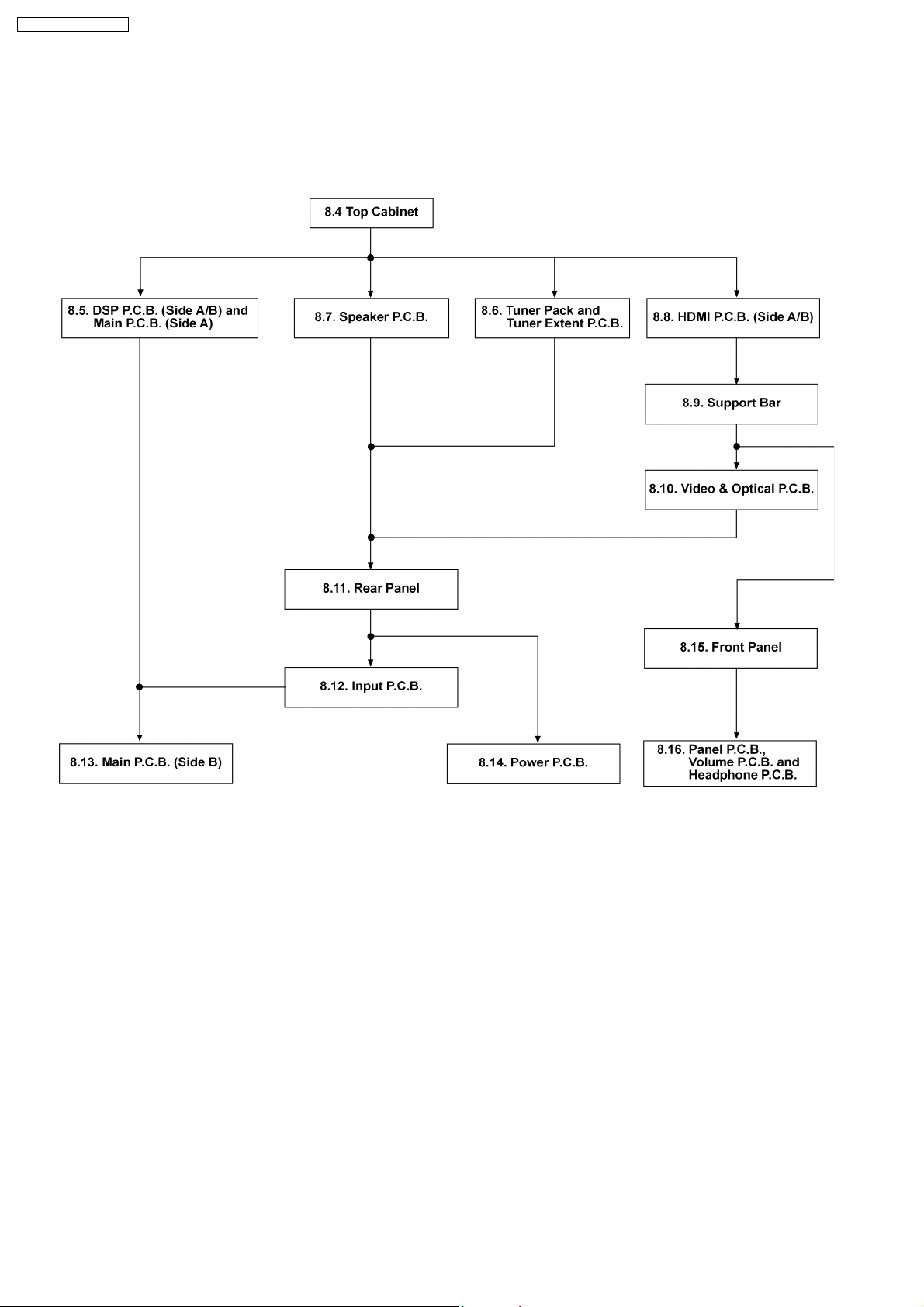
8.2. Disassembly flow chart
The following chart is the procedure for disassembling the casing and inside parts for internal inspection when carrying out the
servicing.
To assemble the unit, reverse the steps shown in the chart below.
28
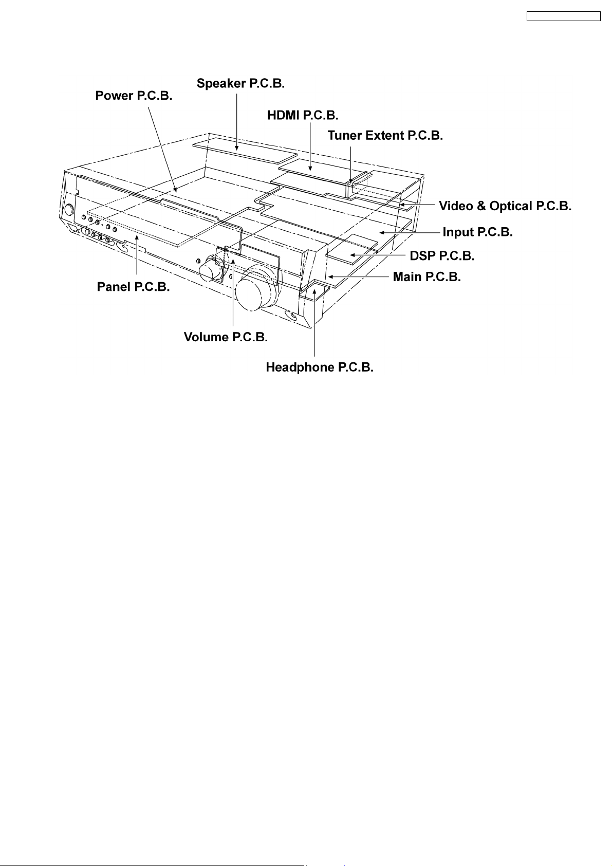
8.3. Main Parts Location Diagram
SA-XR58E / SA-XR58EG
29
SA-XR58E / SA-XR58EG
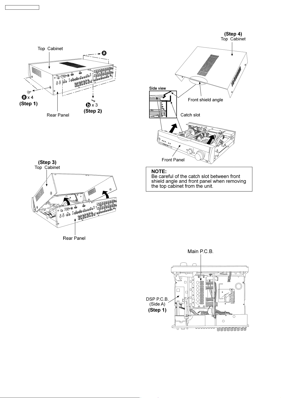
8.4. Disassembly of Top Cabinet
Step 1 : Remove 4 screws (Top cabinet).
Step 2 : Remove 3 screws (Rear panel).
Step 3 : Lift up the top cabinet as arrow shown.
Step 4 : Remove the top cabinet.
8.5. Disassembly and Checking the
DSP P.C.B. (Side A/B) and
Main P.C.B. (Side A)
· Follow the (Step 1) - (Step 4) of item 8.4.
Step 1 : Check the DSP P.C.B. (Side A).
30
 Loading...