

Panasonic SAVK-82-DGCP, SAVK-82-DGCS, SAVK-82-DGS Service manual
A
A
A
A
A
r
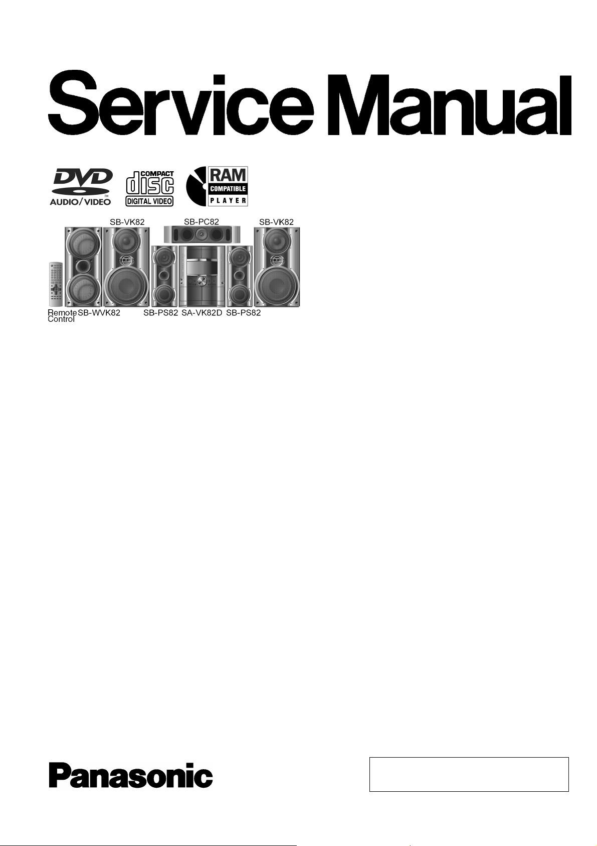
DVD Stereo System
SA-VK82DGCP
SA-VK82DGCS
SA-VK82DGS
Colour
(S)... Silver Type
ORDER NO. MD0506224C3
Specifications
AMPLIFIER SECTION
RMS Output Power: Dolby Digital Mode
Main
85 W per channel (4 Ω), 1 kHz, 10% THD
Surround Ch
60 W per channel (4 Ω), 1 kHz, 10% THD
Center Ch
80 W per channel (4 Ω), 1 kHz, 10% THD
Subwoofer Ch
90 W per channel (4 Ω), 100 Hz, 10% THD
Total RMS Dolby Digital mode power
460 W
PMPO output power 5600 W
FM/AM TUNER, TERMINALS SECTION
Preset station FM 15 stations
AM 15 stations
Frequency Modulation (FM)
Frequency range 87.50 - 108.00 MHz (50 kHz step)
Sensitivity 2.5 µV (IHF)
S/N 26dB 2.2 µV
ntenna terminals 75 Ω (unbalanced)
mplitude Modulation (AM)
Frequency range 522 - 1629 kHz (9 kHz step)
520 - 1630 kHz (10 kHz step)
M Sensitivity S/N 20dB at 999 kHz
560 µV/m
udio performance (Amplifier)
Input sensitivity/Input impedance
ux 250 mV, 20 kΩ
Phone jack
Terminal Stereo, 3.5 mm jack
Mic jack
Sensitivity 0.7 mV, 600 Ω
Terminal Mono, 6.3 mm jack (2 system)
CASSETTE DECK SECTION
Type Auto-Reverse
Track system 4-Track, 2 Channel
Head Record/Playback Solid permalloy head
Erasure Double gap ferrite head
Motor DC servo moto
Recording System AC Bias 100 kHz
Erasing System AC Erase 100 kHz
Tape Speed 4.8 cm/s
Overall frequency response (+3, -6 dB) at DECK OUT
Normal 35 Hz - 14 kHz
S/N Ratio 50 dB (A weighted)
Wow and Flutter 0.18 % (WRMS)
Fast Forward and Rewind Time Approx. 120 seconds with
C-60 cassette tape
DISC SECTION
Disc played [8 cm or 12 cm]
(1) DVD (DVD-Video, DVD-Audio)
(2) DVD-RAM (DVD-VR, JPEG*4,*5)
(3) DVD-R (DVD-Video)
© 2005 Matsushita Electric Industrial Co. Ltd.. All
rights reserved. Unauthorized copying and
distribution is a violation of law.
*1
*2
*3
*4
*5
A
A
SA-VK82DGCP / SA-VK82DGCS / SA-VK82D GS
(4) DVD-RW (DVD-Video)
+ R/RW (Video)
(5) CD,CD-R/RW [CD-DA, Video CD, SVCD*1, MP3*2,*5, WMA*3,*5,
JPEG*4,*5, HighMAT Level 2 (Audio and Image)]
Conforming to IEC62107
MPEG-1 Layer 3, MPEG-2 Layer 3
Windows Media Audio Ver.9.0. Class 2A
Not compatible with Multiple Bit Rate (MBR)
Exif Ver 2.1 JPEG Baseline files
Picture resolution: between 160 x 120 and 6144 x 4096 pixels (Sub
sampling is 4:2:2 or 4:2:0)
The total combined maximum number of recognizable audio and
picture contents and groups: 4000 audio and picture contents and
400 groups.
Pick up
Wavelength
CD 785 nm
DVD 662 nm
udio output (Disc)
Number of channels 5.1ch(FL,FR,C,SL,SR,SW)
udio performance (measurement at: Line out terminal)
Frequency response
CD-Audio 4Hzto20kHz(+1dB,-2dB)
VIDEO SECT ION
Video system
Signal system PAL625/50, PAL525/60, NTSC
Composite video output
Output level 1 Vp-p (75 Ω )
Terminal Pinjack(1system)
S-video output
Y output level 1 Vp-p (75 Ω )
C output level 0.3Vp-p(75Ω)(PAL)
0.286 Vp-p (75 Ω)(NTSC)
Terminal S terminal (1 system)
Component video output
[NTSC: 525 (480)p/525 (480)i, PAL: 625 (576)p/625 (576)i]
Y output level 1 Vp-p (75 Ω )
PBoutput level 0.7Vp-p(75Ω)
PRoutput level 0.7Vp-p(75Ω)
Terminal
Pin jack (Y: green, PB:blue,PR:red)(1system)
GENERAL
Power supply
AC 110 to 127V/220 to 240 V, 50/60Hz
Power consumption 365 W
Power consumption in standby mode:
0.9 W (approximate)
Dimensions (W x H x D) 250 x 330 x 348 mm
Mass 9.4 kg
Operating temperature range +5°C to +35°C
Operating humidity range 5% to 90% RH (no condensation)
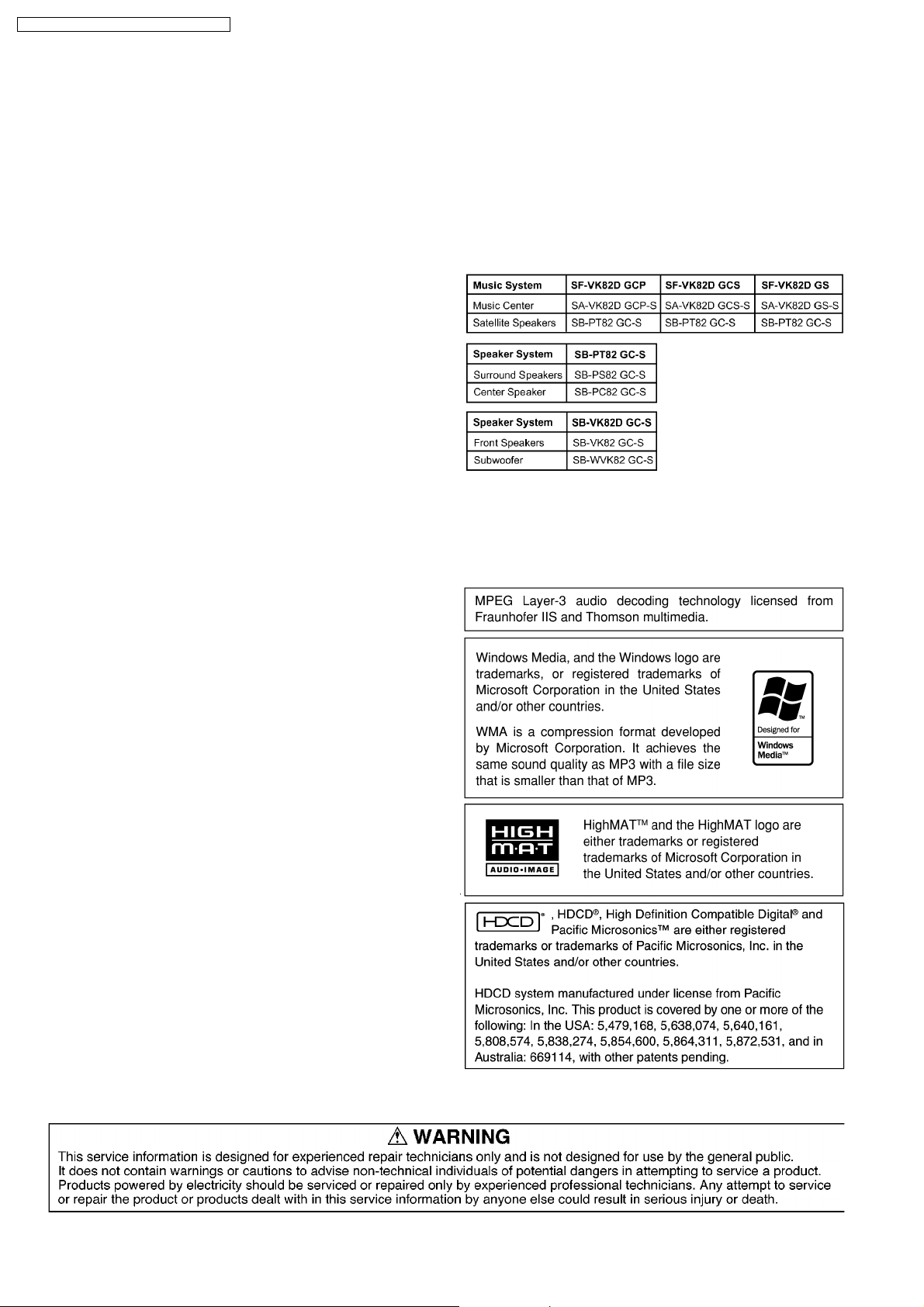
SYSTEM
SC-VK82D (GCP) Music System: SF-VK82D (GCP)
Speakers: SB-VK82D (GC)
SC-VK82D (GCS) Music System: SF-VK82D (GCS)
Speakers: SB-VK82D (GC)
SC-VK82D (GS) Music System: SF-VK82D (GS)
Speakers: SB-VK82D (GC)
Notes:
1. Specifications are subject to change without notice. Mass and
dimensions are approximate.
2. Total harmonic distortion is measured by the digital spectrum
analyzer.
2

SA-VK82DGCP / SA-VK82DG CS / SA-VK82DGS
CONTENTS
Page Page
1 Safety precautions for AC Cord (For GS only) 5
2 Before Use (Caution)
3 Before Repair and Adjustment
4 Protection Circuitry
5 Safety Precautions
5.1. General Guidelines
6 Prevention of Electro Static Discharge (ESD) to
Electrostatically Sensitive (ES) Devices
7 Handling the Lead-free Solder
7.1. About lead free solder (PbF)
8 Precaution of Laser Diode
9 Cautions to be taken when handling Optical Pickup
9.1. Handling Optical Pickup
9.2. Replacing Precautions for Optical Pickup Unit
9.3. Grounding for Preventing Electrostatic Destruction
10 Accessories
11 Operation Procedures
12 Disc information
13 About HighMAT
13.1. What 痴 HighMAT?
13.2. Why take advantage of HighMAT?
13.3. Benefits of HighMAT?
14 Optical Pickup Self-Diagnosis and Replacement Procedure
14.1. Optical Pickup Breakdown diagnosis
15 Self-Diagnosis Function
15.1. Entering into Self-Diagnostic Mode
15.2. Automatic Displayed Error Codes
15.3. Memorized Error Codes
15.4. Service Mode Table 1
15.5. DVD/CD Self-Diagnosis Error Code Description
15.6. Mode Table 2
15.7. CR16 Mechanism Ageing Mode
15.8. Operation Lock Function
15.9. Things to Do After Repair
16 Cautions To Be Taken During Servicing
16.1. Recovery after the dvd player is repaired
16.2. DVD Player Firmware Version Upgrade Process
16.3. Firmware Version Upgrade Process by Using Disc and
Recovery Process
16.4. Using Recovery Disc
16.5. Total Usage Time Display
16.6. After replacement of DVD Module
17 Disassembly and Assembly of Main Component
17.1. Disassembly steps
17.2. Disassembly flow chart
17.3. Disassembly of Top Cabinet
17.4. Disassembly of Rear Panel
17.5. Disassembly of DVD Changer Unit
17.6. Disassembly of Main P.C.B.
17.7. Disassembly of Power Amp P.C.B.
17.8. Disassembly of Power P.C.B.
10
11
13
15
15
15
16
19
19
20
20
20
20
21
21
21
24
24
25
25
25
25
25
26
26
26
27
27
28
29
29
29
30
31
32
17.9. Disassembly of Transformer P.C.B. & Voltage Selector
5
5
5
6
6
7
7
7
8
9
9
9
9
17.10. Disassembly of Front Panel Unit
17.11. Disassembly for Mic P.C.B. & Panel P.C.B.
17.12. Disassembly of Deck Mechanism Unit
17.13. Replacement for Deck P.C.B.
17.14. Replacement for Traverse Deck
17.15. Replacement for Optical Pickup Unit (DVD mechanism)
17.16. Procedure for removing CD loading mechanism
17.17. CR16 mechanism disassemb ly procedure
17.18. CR16 mechanism assembly procedure
17.19. Disassembly for Traverse Unit
17.20. Replacement for cassette lid
17.21. Rectification for tape jam problem
18 Checking for major P.C.Bs
18.1. Checking of Main P.C.B.
18.2. Checking of Transforme r P.C.B.
18.3. Checking of Panel, Deck & Deck Mechanism P.C.B.
18.4. Checking of Power P.C.B.
19 Measurements and Adjustments
19.1. Cassette Deck Section
19.2. Tuner Section
19.3. Alignment Points
20 Block Diagram
21 Voltage Measurement
22 Schematic Diagram
22.1. Optical Pickup Unit Circuit
22.2. (A) DVD Module Circuit
22.3. (B) Main (Tuner) Circuit
22.4. (B) Main Circuit
22.5. (C) Panel Circuit & (D) Mic Circuit
22.6. (E) Deck Circuit & (F) Deck Mechanism Circuit
22.7. (G) Power Circuit
22.8. (H) Power Amp Circuit
22.9. (I) Transformer Circuit
22.10. (J) CD Loading Circuit
23 Printed Circuit Board
23.1. (A) DVD Module P.C.B. (Side: A & B )
23.2. (B) Main P.C.B.
23.3. (C) Panel P.C.B.
23.4. (D) Mic P.C.B. & (K) Tuner Pack P.C.B.
23.5. (E) Deck P.C.B. & (F) Deck Mechanism P.C.B.
23.6. (G) Power P.C.B. & (H) Power Amp P.C.B.
23.7. (I) Transformer P.C.B.
23.8. (J) CD Loading P.C.B.
24 Wiring Connection Diagram
25 Illustration of ICs, Transistors and Diodes
26 Terminal Function of IC
26.1. IC2818 (C2CBJG000653) System Microprocessor
27 Parts Location and Replacement Parts List
27.1. Deck Mechanism (RAA3413-S)
27.2. DVD Loading Mechanism
33
33
35
36
36
36
37
40
40
46
58
59
60
61
61
62
63
64
65
65
66
67
68
79
80
81
82
89
90
99
101
103
104
105
106
107
107
109
111
113
114
115
117
118
119
121
123
123
125
126
129
3

SA-VK82DGCP / SA-VK82DG CS / SA-VK82DGS
27.3. Cabinet 132
27.4. Electrical Parts List
135
27.5. Packing Materials & Accessories Parts List
27.6. Packaging
148
149
4
SA-VK82DGCP / SA-VK82DG CS / SA-VK82DGS
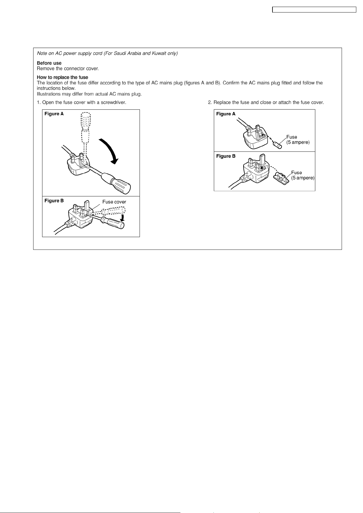
1 Safety precautions for AC Cord (For GS only)
2 Before Use (Caution)
Be sure to disconnect the AC cord before adjusting the voltage selector.
Use a minus(-) screwdriver to set the voltage selector (on the rear panel) to the voltage setting for the area in which the unit will
be used. (If the power supply in your area is 110-127V or 220-240V.)
Note that this unit will be seriously damaged if this setting is not made correctly. (There is no voltage selector for some countries,
the correct voltage is already set.)
3 Before Repair and Adjustment
Disconnect AC power, discharge Power Supply Capacitors C5815, C5818, C9513, C9533, C9534, C9816 and C9817 through a
10Ω, 5W resistor to ground.
DO NOT SHORT-CIRCUIT DIRECTLY (with a screwdriver blade, for instance), as this may destroy solid state devices.
After repairs are completed, restore power gradually using a variac, to avoid overcurrent.
Current consumption at AC 100/110V at 50/60 Hz & AC 240V at 50Hz in NO SIGNAL (vol. min, at CD mode) should be ~500mA
.
4 Protection Circuitry
The protection circuitry may have operated if either of the following conditions are noticed:
No sound is heard when the power is turned on.
·
Sound stops during a performance.
·
The function of this circuitry is to prevent circuitry damage if, for example, the positive and negative speaker connection wires are
“shorted”, or if speaker systems with an impedance less than the indicated rated impedance of the amplifier are used.
If this occurs, follow the procedure outlines below:
1. Turn off the power.
5

SA-VK82DGCP / SA-VK82DG CS / SA-VK82DGS
2. Determine the cause of the problem and correct it.
3. Turn on the power once again after one minute.
Note :
When the protection circuitry functions, the unit will not operate unless the power is first turned off and then on again.
5 Safety Precautions
5.1. General Guidelines
1. When servicing, observe the original lead dress. If a short circuit is found, replace all parts which have been overheated or
damaged by the short circuit.
2. After servicing, see to it that all the protective devices such as insulation barriers, insulation papers shields are properly
installed.
3. After servicing, make the following leakage current checks to prevent the customer from being exposed to shock hazards.
5.1.1. Leakage Current Cold Check
1. Unplug the AC cord and connect a jumper between the two prongs on the plug.
2. Measure the resistance value, with an ohmmeter, between the jumpered AC plug and each exposed metallic cabinet part on
the equipment such as screwheads, connectors, control shafts, etc. When the exposed metallic part has a return path to the
chassis, the reading should be between 1MΩ and 5.2MΩ.
When the exposed metal does not have a return path to the chassis, the reading must be
.
Figure 1
5.1.2. Leakage Current Hot Check
(See Figure 1)
1. Plug the AC cord directly into the AC outlet. Do not use an isolation transformer for this check.
2. Connect a 1.5kΩ, 10 watts resistor, in parallel with a 0.15µF capacitor, between each exposed metallic part on the set and a
good earth ground such as a water pipe, as shown in Figure 1.
3. Use an AC voltmeter, with 1000 ohms/volt or more sensitivity, to measure the potential across the resistor.
4. Check each exposed metallic part, and measure the voltage at each point.
5. Reverse the AC plug in the AC outlet and repeat each of the above measurements.
6. The potential at any point should not exceed 0.75 volts RMS. A leakage current tester (Simpson Model 229 or equivalent) may
be used to make the hot checks, leakage current must not exceed 1/2 milliamp. In case a measurement is out of the limits
specified, there is a possibility of a shock hazard, and the equipment should be repaired and rechecked before it is returned to
the customer.
6
SA-VK82DGCP / SA-VK82DG CS / SA-VK82DGS
6 Prevention of Electro Static Discharge (ESD) to
Electrostatically Sensitive (ES) Devices
Some semiconductor (solid state) devices can be damaged easily by electricity. Such components commonly are called
Electrostatically Sensitive (ES) Devices. Examples of typical ES devices are integrated circuits and some field-effect transistors and
semiconductor “chip” components. The following techniques should be used to help reduce the inciden ce of component damage
caused by electro static discharge (ESD).
1. Immediately before handling any semiconductor component or semiconductor-equipped assembly, drain off any ESD on your
body by touching a known earth ground. Alternatively, obtain and wear a commercially available discharging ESD wrist strap,
which should be removed for potential shock reasons prior to applying power to the unit under test.
2. After removing an electrical assembly equipped with ES devices, place the assembly on a conductive surface such as
aluminium foil, to prevent electrostatic charge build up or exposu re of the assembly.
3. Use only a grounded-tip soldering iron to solder or unsolder ES devices.
4. Use only an anti-static solder remover device. Some solder removal devices not classified as “anti-static (ESD protected)” can
generate electrical charge to damage ES devices.
5. Do not use freon-propelled chemicals. These can generate electrical charges sufficient to damage ES devices.
6. Do not remove a replacement ES device from its protective package until immediately before you are ready to install it. (Most
replacement ES devices are packaged with leads electrically shorted together by conductive foam, aluminium foil or
comparable conductive material).
7. Immediately before removing the protective material from the leads of a replacement ES device, touch the protective material
to the chassis or circuit assembly into which the device will be installed.
Caution
Be sure no power is applied to the chassis or circuit, and observe all other safety precautions.
8. Minimize body motions when handling unpackaged replacement ES devices. (Otherwise harmless motion such as the brushing
together of your clothes fabric or the lifting of your foot from a carpeted floor can generate static electricity (ESD) sufficient to
damage an ES device).
7 Handling the Lead-free Solder
7.1. About lead free solder (PbF)
Distinction of PbF P.C.B.:
P.C.B.s (manufactured) using lead free solder will have a PbF stamp on the P.C.B.
Caution:
· Pb free solder has a higher melting point than standard solder; Typically the melting point is 50 - 70°F (30 - 40°C) higher. Please
use a high temperature soldering iron. In case of soldering iron with temperature control, please set it to 700 ± 20°F (370 ±
10°C).
· Pb free solder will tend to splash when heated too high (about 1100°F/600°C).
· W hen soldering or unsoldering, please completely remove all of the solder on the pins or solder area, and be sure to heat the
soldering points with the Pb free solder until it melts enough.
7
SA-VK82DGCP / SA-VK82DG CS / SA-VK82DGS
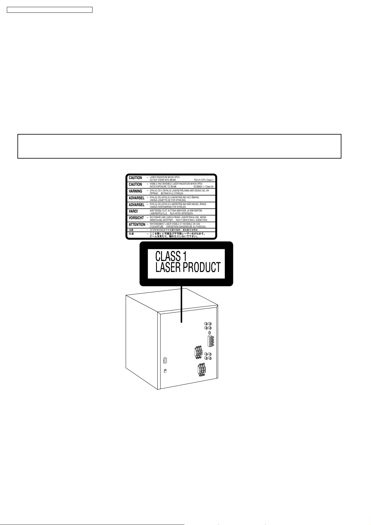
8 Precaution of Laser Diode
Caution :
This product utilizes a laser diode with the unit turned "ON", invisible laser radiation is emitted from the pick up lens.
Wavelength : 785 nm(CD)/662 nm(DVD)
Maximum output radiation power from pick up : 100 µW/VDE
Laser radiation from pick up unit is safety level, but be sure the followings:
1. Do not disassemble the optical pick up unit, since radiation from exposed laser diode is dangerous.
2. Do not adjust the variable resistor on the pick up unit. It was already adjusted.
3. Do not look at the focus lens using optical instruments.
4. Recommend not to look at pick up lens for a long time.
CAUTION!
THIS PRODUCT UTILIZES A LASER.
USE OF CONTROLS OR ADJUSTMENTS OR PERFORMANCE OF PROCEDURES OTHER THAN THOSE SPECIFIED HEREIN MAY RESULT
IN HAZARDOUS RADIATION EXPOSURE.
n Use of Caution Labels
8
SA-VK82DGCP / SA-VK82DG CS / SA-VK82DGS
9 Cautions to be taken when handling Optical Pickup
The laser diode used inside optical pickup could be destroyed due to static electricity as a potential difference is caused by
electrostatic load discharged from clothes or human body. Handling the parts carefully to avoid electrostatic destruction during
repair.
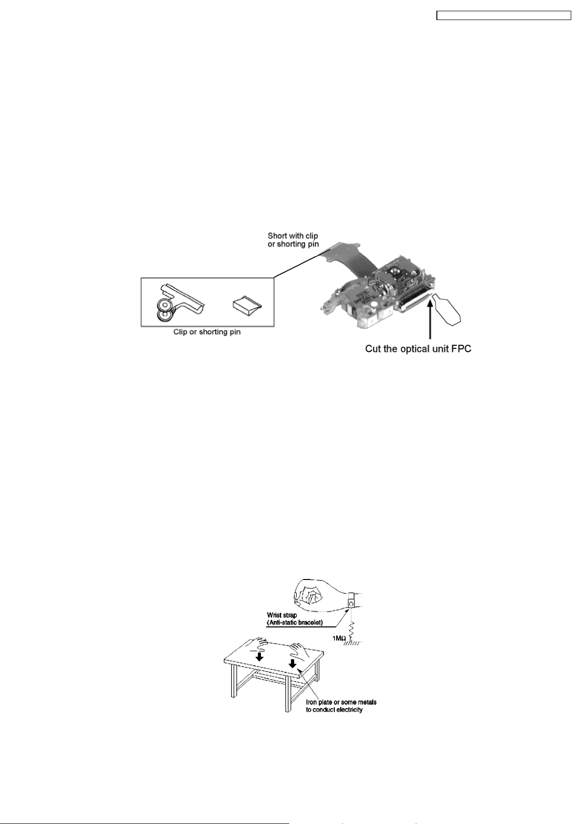
9.1. Handling Optical Pickup
1. Do not impact on optical pickup as the unit structurally uses an extremely precise technology.
2. Short-circuit the flexible cable of optical pickup remove from the circuit board using a short-circuit pin or clip in order to prevent
laser diode from electrostatic destruction (Refer to Fig. 9.1 and Fig. 9.2)
3. Do not handle flexible cables forcibly as this may cause snapping. Handle the parts carefully (Refer to Fig. 9.1)
4. A new optical pickup is equipped with an anti-static flexible cable. After replacing and connecting to the flexible board, cut the
anti-static flexible cable. (Refer to Fig. 9.1)
Fig. 9.1
9.2. Replacing Precautions for Optical Pickup Unit
DVD/CD Optical Pickup
The optical pickup by which part supply was carried out attaches the short clip to the flexible board for laser diode electrostatic
discharge damage prevention. Please remove the short clip and be sure to check that the short land is open, before connecting.
(Please remove solder, when the short land short-circuits.)
9.3. Grounding for Preventing Electrostatic Destruction
1. Human body grounding
Use the anti-static wrist strap to discharge the static electricity accumulated in your body. (Refer to Fig. 9.2)
2. Work place grounding
Place a conductive material (conductive sheet) or iron board where optical pickup is placed. (Refer to Fig. 9.2)
Note :
Keep your clothes away from optical pickup as wrist strap does not release the static electricity charged in clothes.
Fig. 9.2
9
SA-VK82DGCP / SA-VK82DG CS / SA-VK82DGS
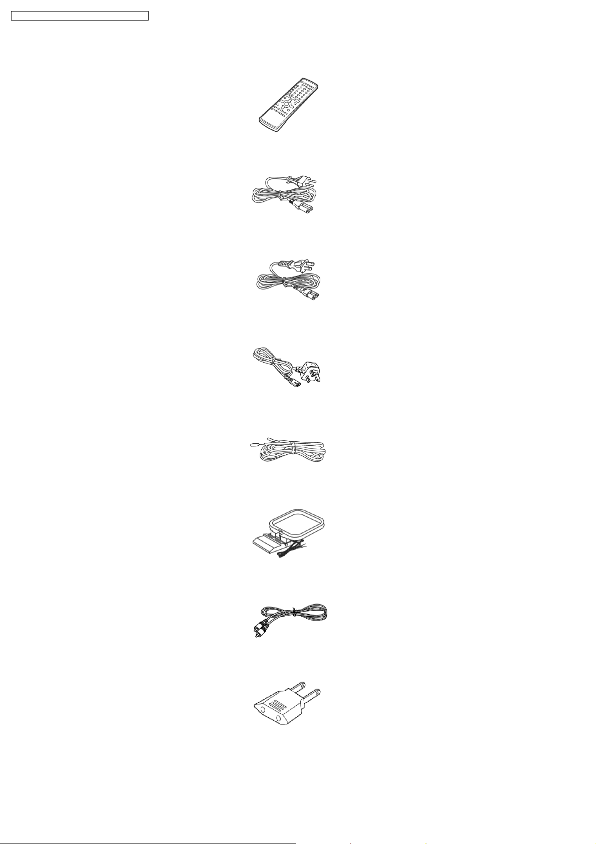
10 Accessories
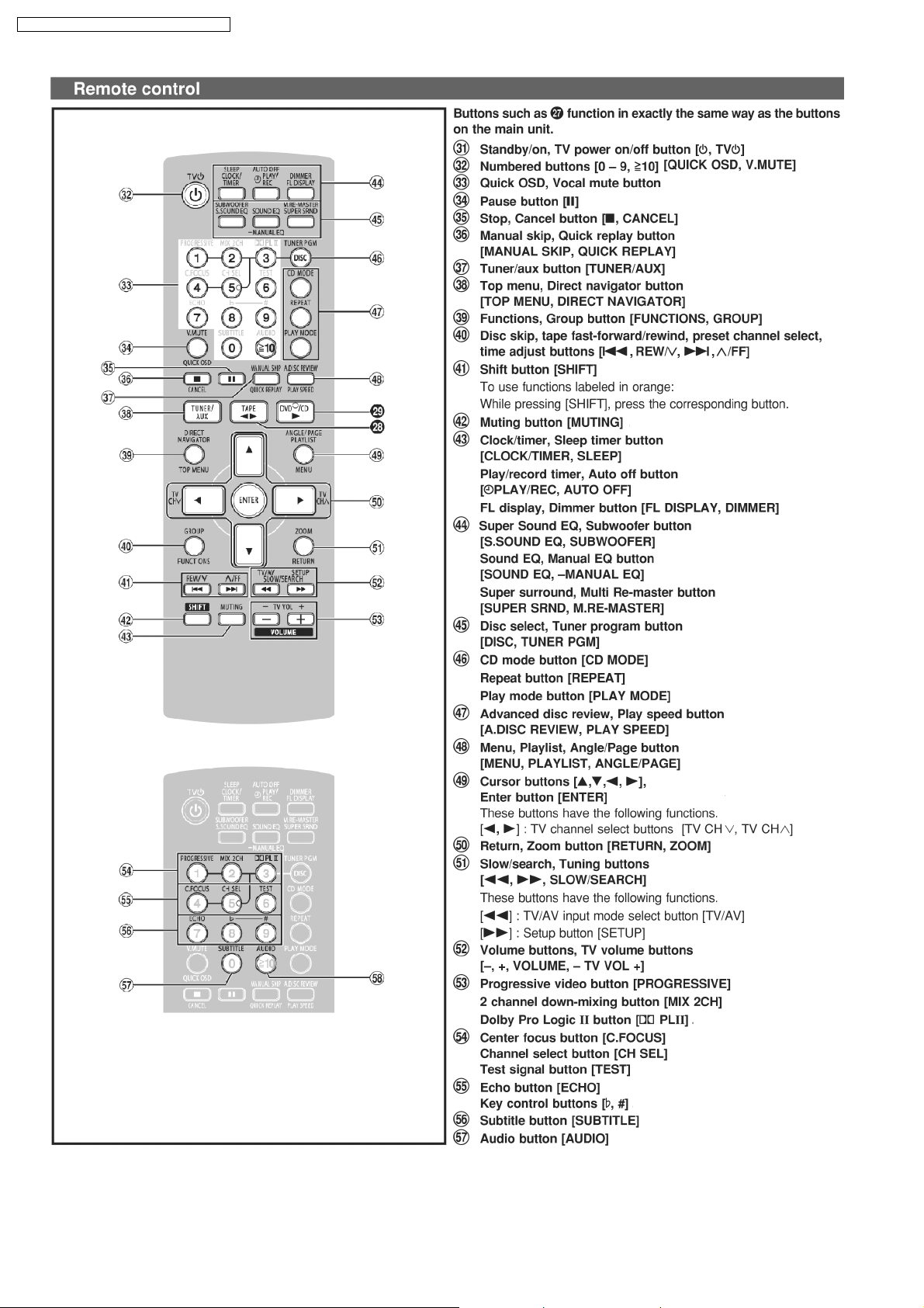
Remote control
AC cord (For GCS only)
AC cord (For GS only)
AC cord (For GS only)
FM antenna
AM antenna
Video cable
AC Plug Adaptor
(For GCP only)
10
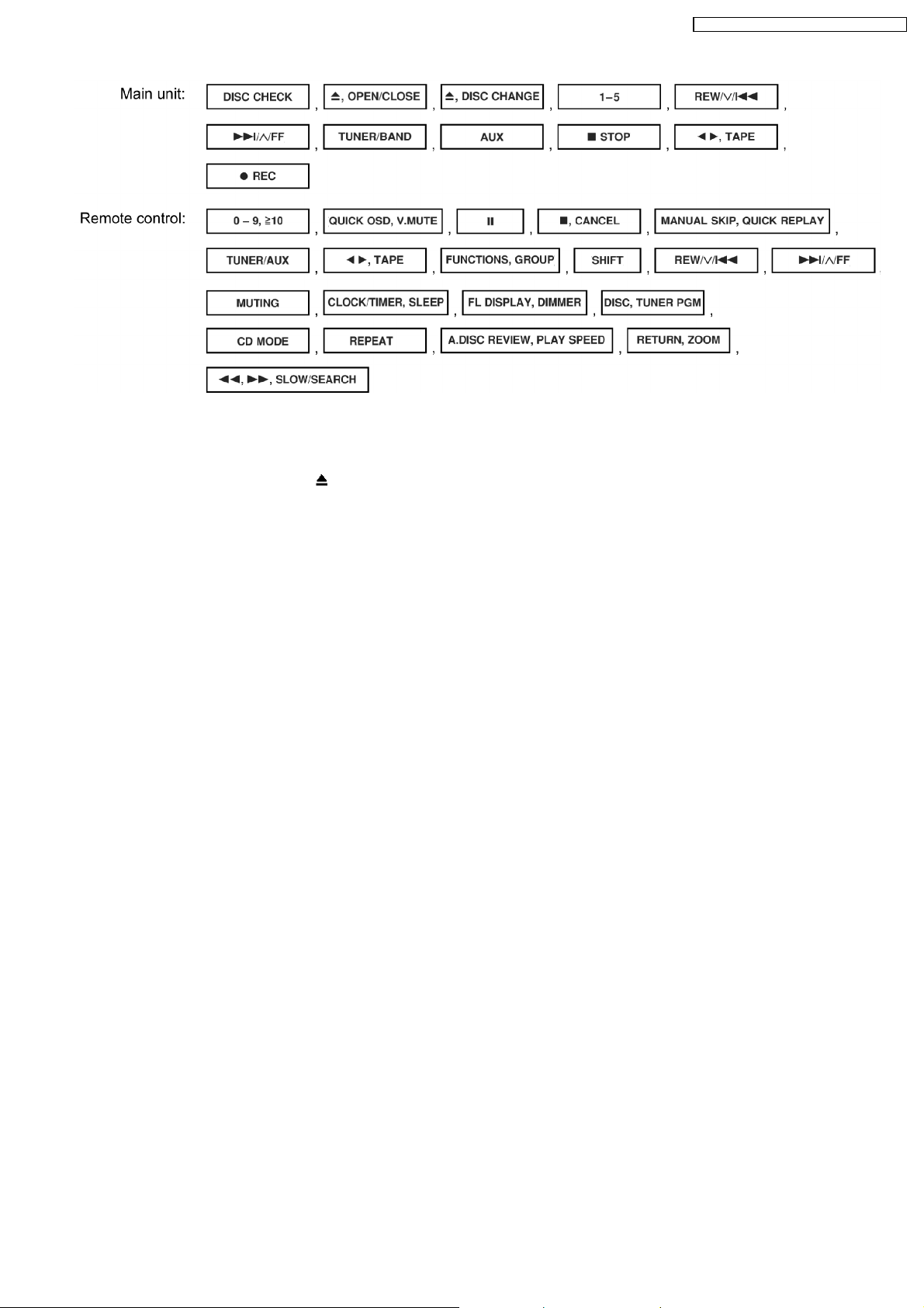
11 Operation Procedures
SA-VK82DGCP / SA-VK82DG CS / SA-VK82DGS
11
SA-VK82DGCP / SA-VK82DG CS / SA-VK82DGS
12
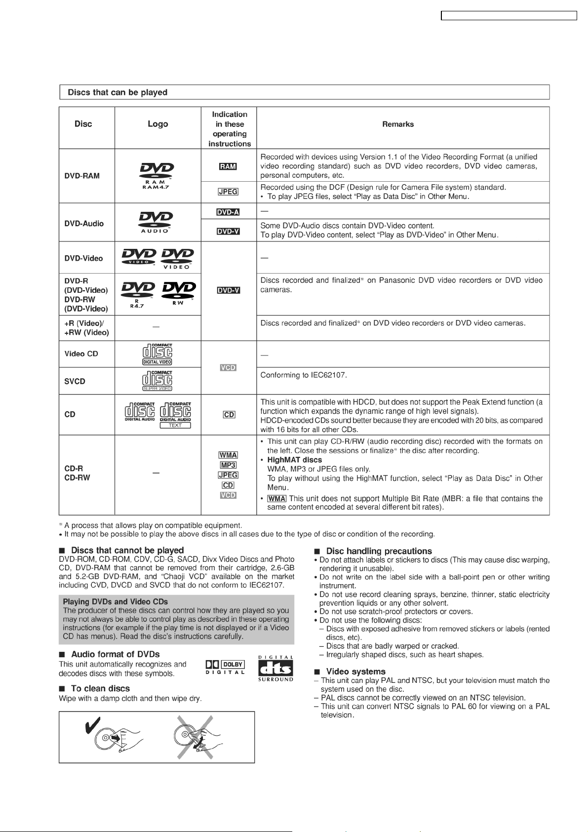
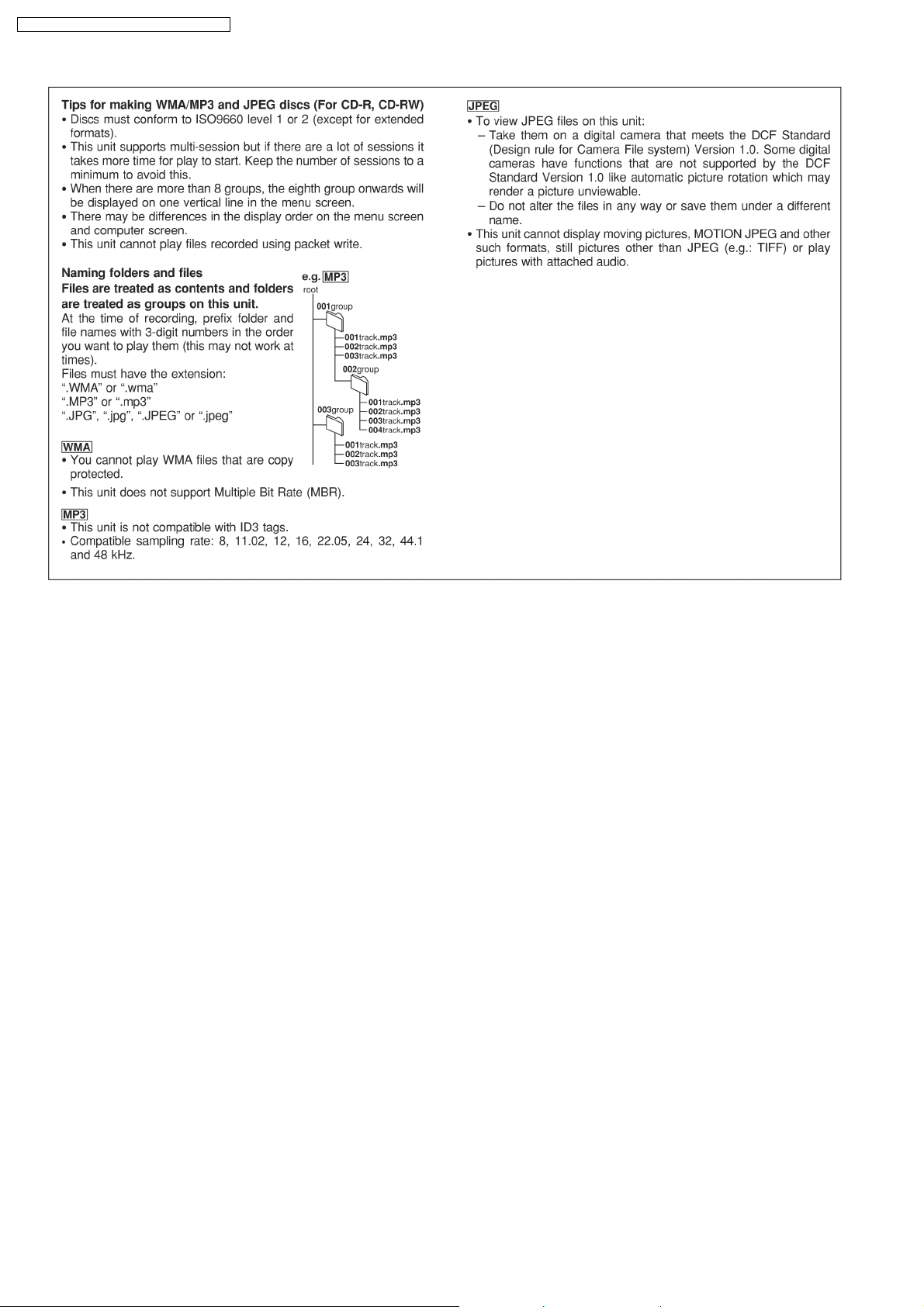
12 Disc information
SA-VK82DGCP / SA-VK82DG CS / SA-VK82DGS
13
SA-VK82DGCP / SA-VK82DG CS / SA-VK82DGS
14
SA-VK82DGCP / SA-VK82DG CS / SA-VK82DGS
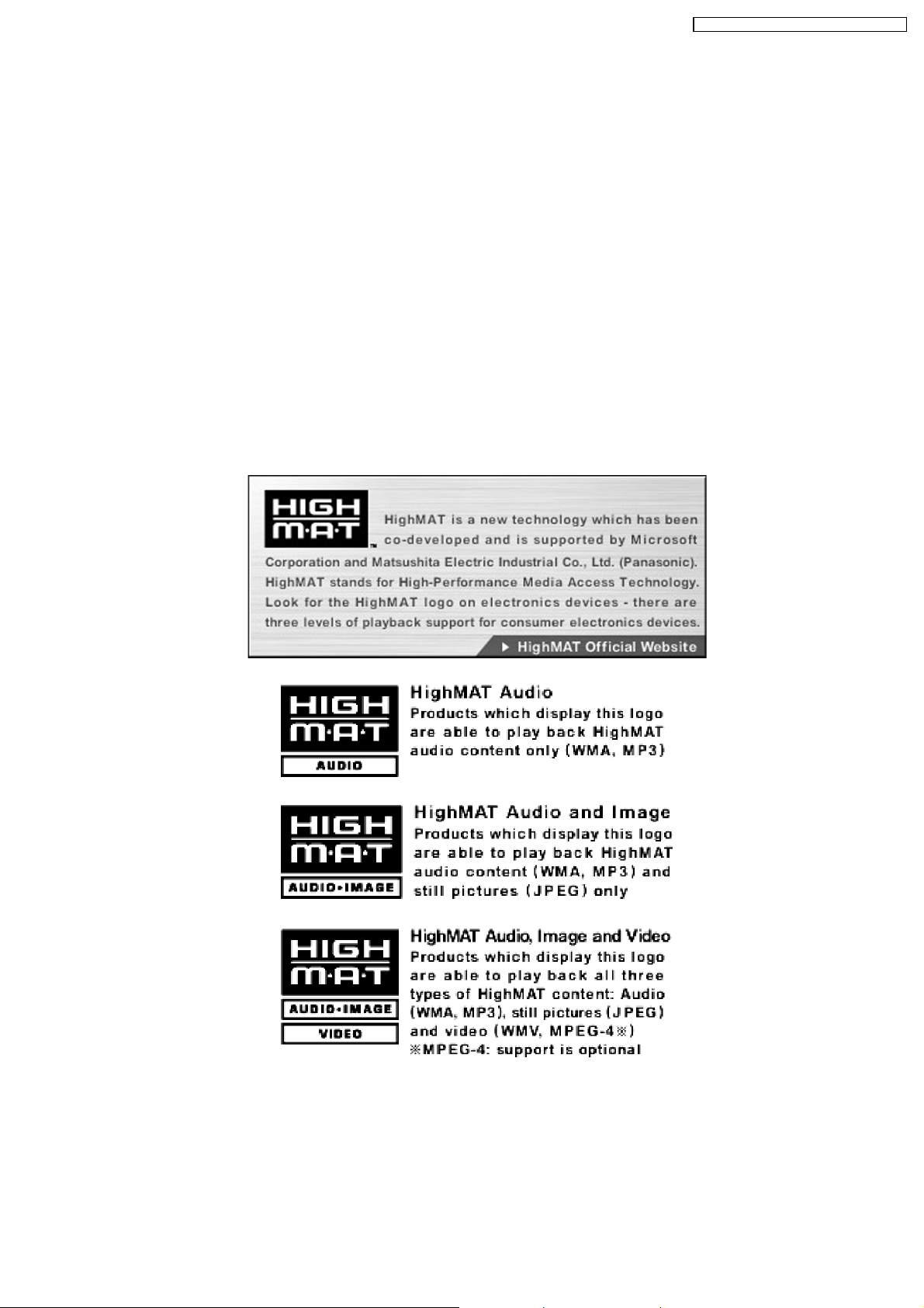
13 About HighMAT
13.1. What’s HighMAT?
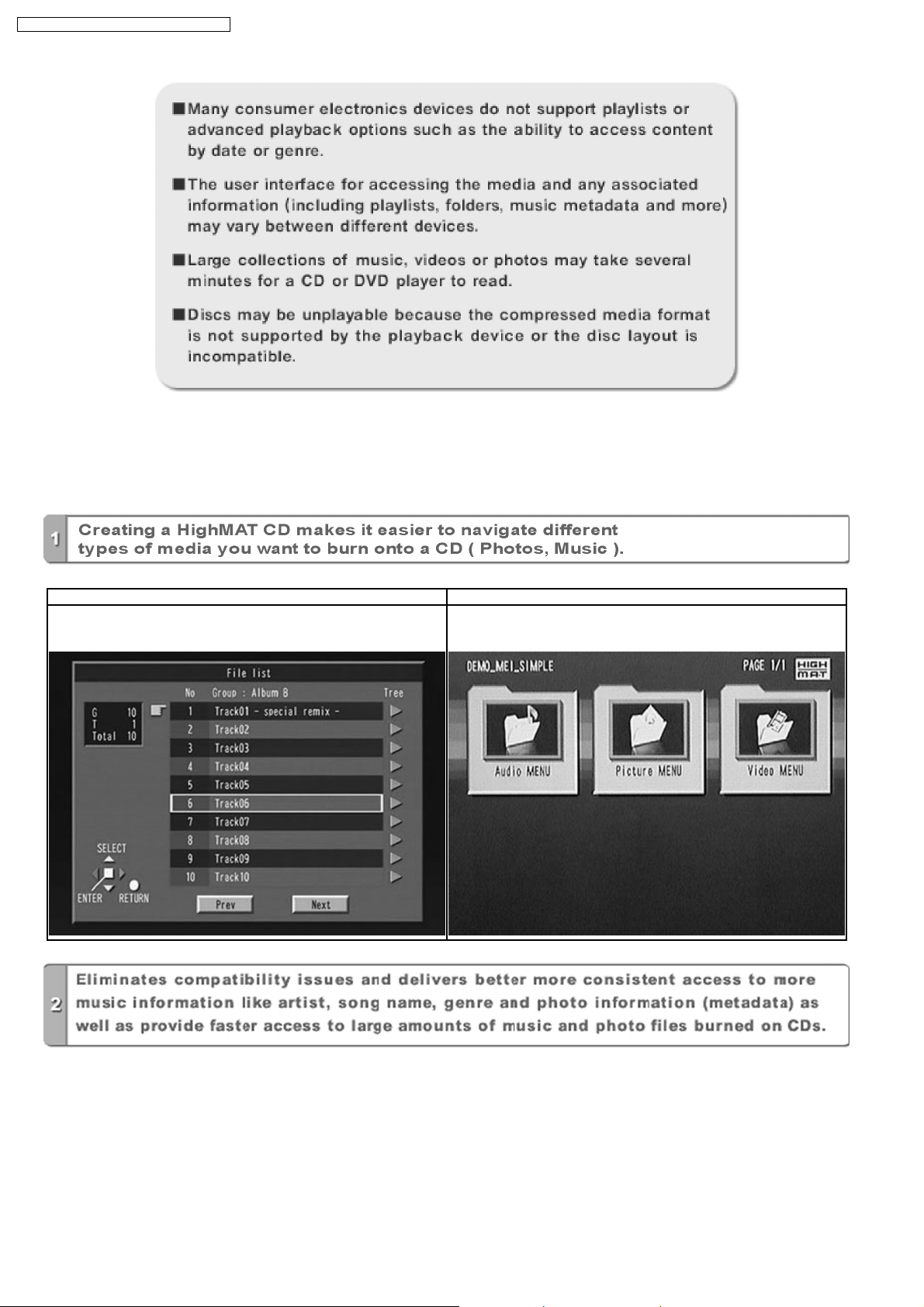
Consumers worldwide are using PCs to create their own collections of music, photos and even video by burning them onto CDs.
But how these collections can be experie nced across different devices can be confusing to navigate, time consum ing to access for
a DVD player, and be incomplete in terms of music information available to the customer.
HighMAT offers a solution to this growing consumer problem. HighMAT dramatically improves the digital media experience on
consumer electronic devices by delivering a simple, standardized approach that allows consumers who have created personal
collections of digital music, photography and video on their PC to:
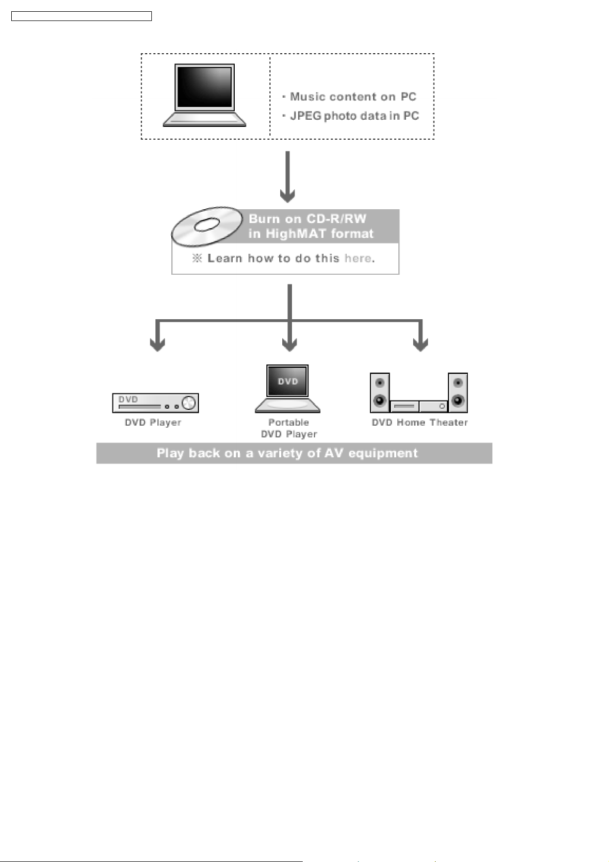
>> Create a HighMAT CD or DVD which can be easily played back on consum er electronics devices such as CD and DVD players,
and car stereos.
>> Move digital media files (using recordable media such as CD-R and CD-RW) between the PC and various playback devices
such as CD and DVD players.
A new standard for creating personal media on consumer electronic devices, HighMAT enable easier and more seamless
interoperability between Windows PCs and devices designed for your living room, or the car.
13.2. Why take advantage of HighMAT?
A Problem Defined:Today, when consumers create their own digital audio, video or photo collections on CD-R or other physic al
formats, there are numerous, inconsistent ways that devices read the data. For the consumer, the playback experience can be
confusing:
15
SA-VK82DGCP / SA-VK82DG CS / SA-VK82DGS
A Solution Created: HighMAT delivers a better digital media access experience by creating a standard approach for PCs to
structure digital media on various physical formats and for playback devices to read the data.
13.3. Benefits of HighMAT?
Conventional HighMAT
Even though DVD player is CD-R/RW compatible, the inconsistent ways
that various DVD players can read the music or photos files often leads
to a confusing and inconsistant playback experince.
HighMAT compatible products play content back with consistent
interface. This includes products which are JPEG compatible products
without HighMAT support.
16
SA-VK82DGCP / SA-VK82DG CS / SA-VK82DGS
17
SA-VK82DGCP / SA-VK82DG CS / SA-VK82DGS
HighMAT is now available for CD Burning and in Leading DVD PlayersHighMAT is a new technology that is now available in leading
software and consumer electronic devices to dramatically improve the digital media experience when you create homemade
CDsHighMAT delivers a simple, standardized way for PC software and consumer electronics devices to talk to each other and work
better together.
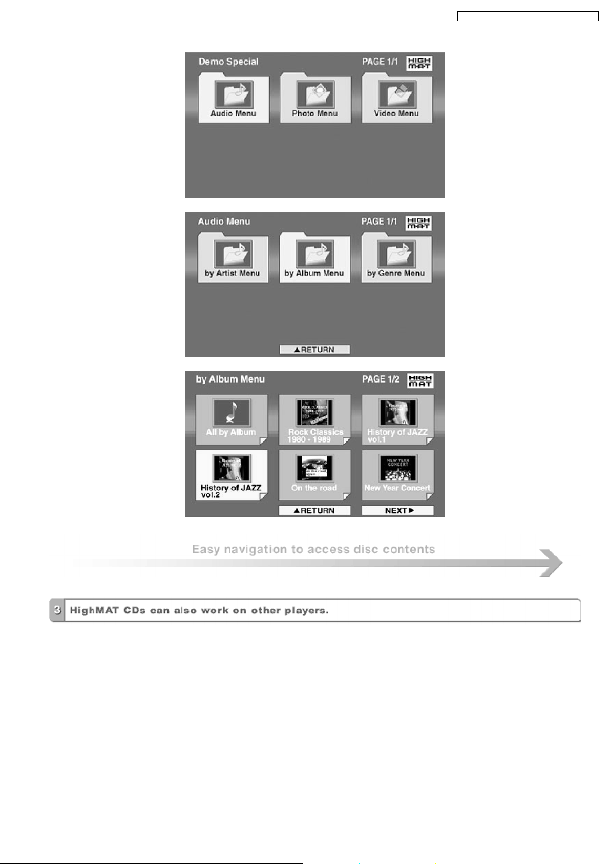
When you create your homemade CDs with software that supports HighMAT CD burning, and then play them back on a DVD
player that supports HighMAT, you get better, easier navigation. You get folders you can access with a single click of your DVD
player´s remote control. You can view important information about your music like full song names, artist titles, album names and
genre. And you can get faster startup on your home entertainment device.
To enjoy the benefits of HighMAT, all you need is software that supports HighMAT for CD burning of music or photos, as well as
a home entertainment device like a DVD player that supports HighMAT for playback. Always look for the HighMAT logo on your
software or home entertainment device to ensure it supports the HighMAT experience.
18
SA-VK82DGCP / SA-VK82DG CS / SA-VK82DGS
14 Optical Pickup Self-Diagnosis and Replacement
Procedure
14.1. Optical Pickup Breakdown diagnosis
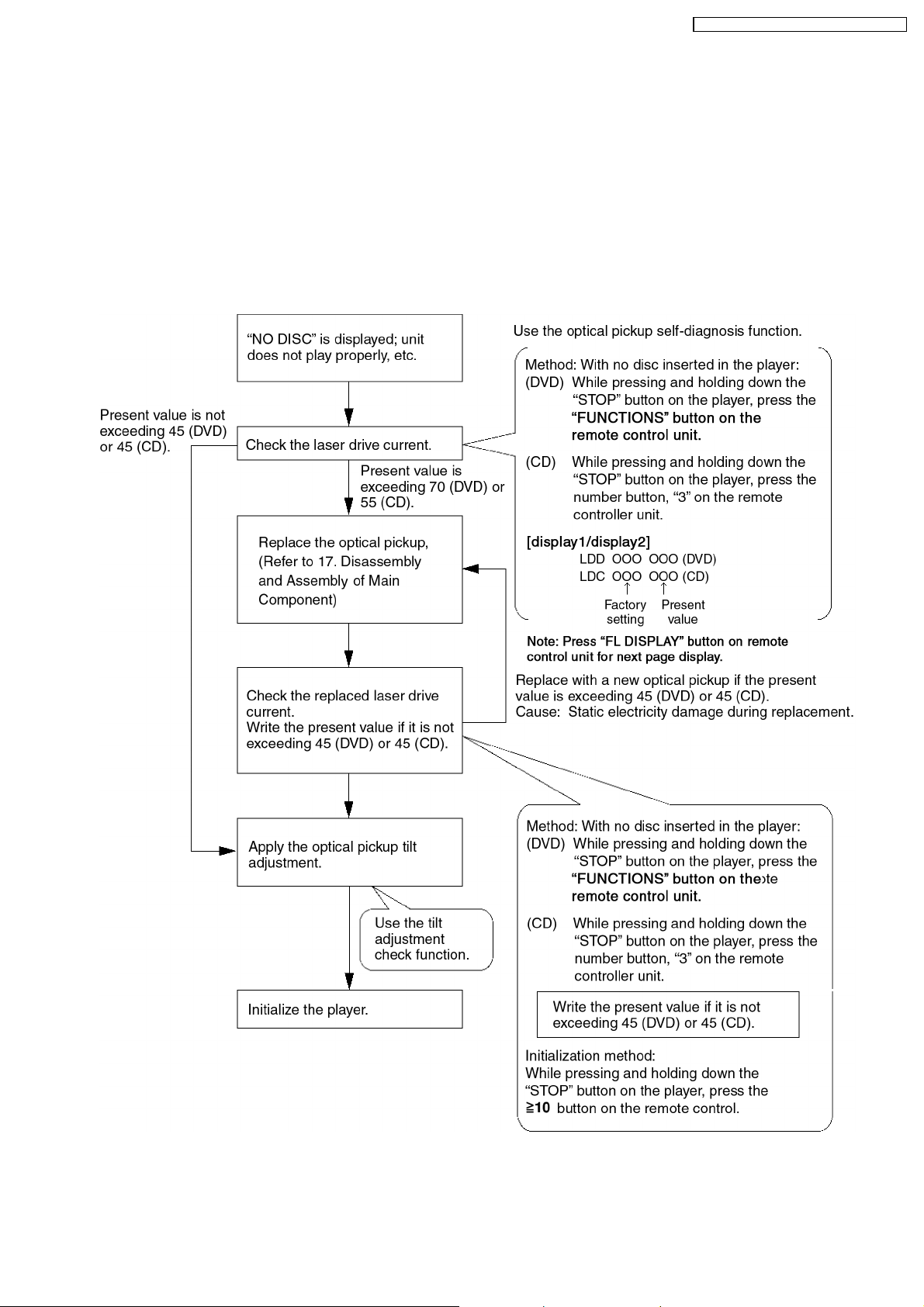
This unit is equipped with the optical pickup self-diagnosis function and the tilt adjustment check function. Follow the procedure
described below during repair in order to perform self-diagnosis and tilt adjustment effectively. Especially when “NO DISC” is
displayed, be sure to apply the self-diagnosis function before replacing with an optical pickup. Replacement of optical pickup
generally requires when the present value of laser drive exceed s 45 (DVD) or 45 (CD).
Note:
Start diagnosis within three minutes after turning on the power (as diagnosis fails when the unit becomes warm).
19
SA-VK82DGCP / SA-VK82DG CS / SA-VK82DGS
15 Self-Diagnosis Function
This unit is equipped with the self-diagnosis function, which display s an error when it occurs, for use during servicing.
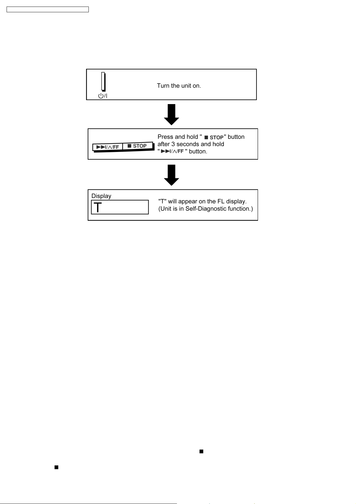
15.1. Entering into Self-Diagnostic Mode
15.2. Automatic Displayed Error Codes
15.2.1. Automatic Display Function
For a power unit error, the code is automatically displayed.
F61: Automatically displayed on the LCD of the player.
15.2.2. Re-Display
· For F61 Display
−
− When the code, F61 is displayed, the power is automatically turned off.
− −
−
− The code, F61 is displayed for three seconds, and then the current time appears.
− −
−
− To retrieve the code, turn on the power button so that the code F61 appears, however, is switched to time display after three
− −
seconds, and the power is automatically turned off.
· For F76 Display
−
− The abnormalities is an output or the abnormalities in a power supply of POWER AMP IC.
− −
15.2.3. Description of Error Code
15.2.3.1. F61
· State, Condition
When the power is turned on, the unit is automatically turned off. The power does not turn on.
· Cause, Troubleshooting
Power circuit system failure and/or direct current flown to speaker terminal
Identify the cause and replace with new parts.
15.3. Memorized Error Codes
15.3.1. Activating Self-Diagnosis Function and Displaying Method
1. Turn on the power.
2. Select DVD/CD function. With no DVD/CD inserted in the player, press
and press the “0” button on the remote control for at least two seconds in order to display “DVD_F---”.
3. Press the
button. If a memorized error is detected, the result of self diagnosis is displayed. (Ex.: T H15)
20
and hold down the button for at least two seconds,
SA-VK82DGCP / SA-VK82DG CS / SA-VK82DGS
If several errors are detected, press the button to display each.
15.3.2. Re-Display
· Press the power button to turn off the power, and then turn on the power.
· The details of self diagnosis are stored in the unit memory.
To retrieve them, follow the procedure described the above, “Activating Self-Diagnosis Function and Displaying Method”.
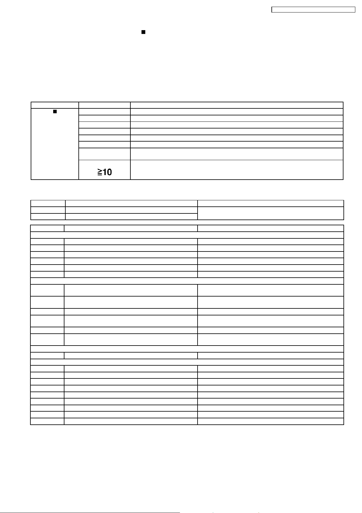
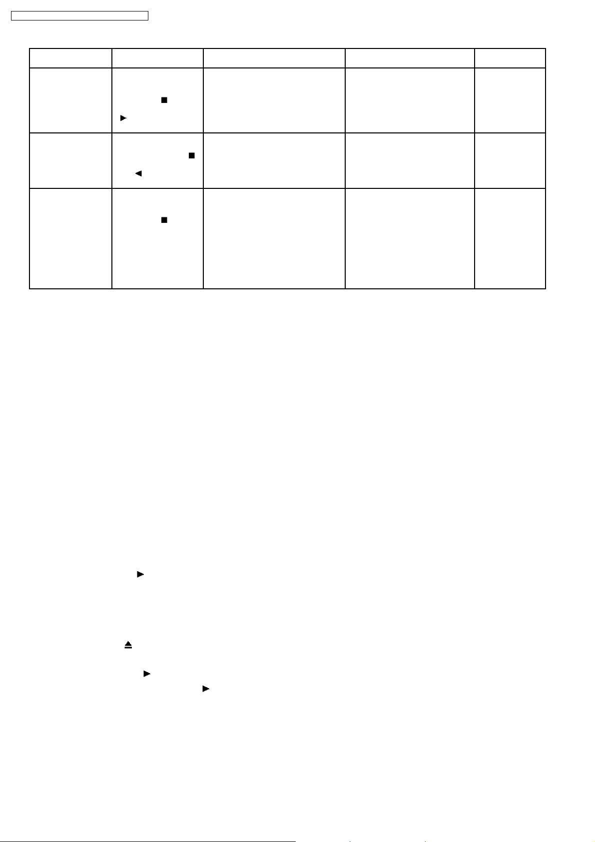
15.4. Service Mode Table 1
Following modes are available with combinations of the pressed buttons on the player and on the remote controller unit.
Player Remote Controller Unit Usage
button
0 Error code display (Refer to the Item 15.5. DVD/CD Self-Diagnosis Error Code Description)
5 Tilt adjustment (Jitter)
6 Region number and broadcasting system check
8 Bulit-in program version check (Micro-P)
FUNCTIONS DVD laser drive current check
3 CD laser drive current check
PAUSE Writing of laser drive current value after replacement of optical pickup
(Do use this function only when optical pickup is replaced.)
Initialization of the player (factory setting is restored.)
Used after replacement of micro-computer and its peripherals and printed circuit board.
15.5. DVD/CD Self-Diagnosis Error Code Description
Error Code State, Conditon Cause, Troublesh ooting
H15 The disc tray cannot be opened: it closes spontaneously. Disc tray open/close detection switch (S1001) failure.
H16 The disc tray cannot be closed: it opens spontaneously.
Error Code Meaning Details
U. H. Error
U11 Focus servo failure
H01 Tray loading failure
H02 Spindle servo failure (Spindle servo, DSC, SP motor, CLV servo failure)
H03 Traverse motor failure
H04 Tracking servo error
H05 Seek timeout failure
DSC system
F500 DSC failure DSC stops due to servo failure.
F501 DSC not Ready failure Communication failure between DSC and system computer
F502 DSC Time out failure See F500.
F503 DSC communication failure Communication failure (Result failure occurs after communication
F505 DSC Attention Error See F500.
F506 Invalid media Disc is placed upside down; TOC is unreadable or invalid disc is
Disc Code
F103 IIlegal highlight position Disc standard is possibly illegal when highlight is displayed.
IIC Error
F4FF Forced initialization failure (Time out)
F880 Unsuitable task number When a message arrives from not existing task
F890 A message is sent during AV task transmission During transmission of a message to AV task
F891 Unable to transmit a message to AV task When transmission of a message to AV task starts
F893 DVD Module problem Check for firmware version
F894 EEPROM failure
F895 Firmware compatibility problem Check for firm version for Main & DVD Module P.C.B.
F897 Initialization is not done properly Follow proper steps for initialization & reset
F8A0 Unsuitable message command When transmission of a message to AV task starts
(Check and replace)
(Startup, focus failure, etc.)
(No communication because DSC does not move)
command is transmitted .)
inserted.
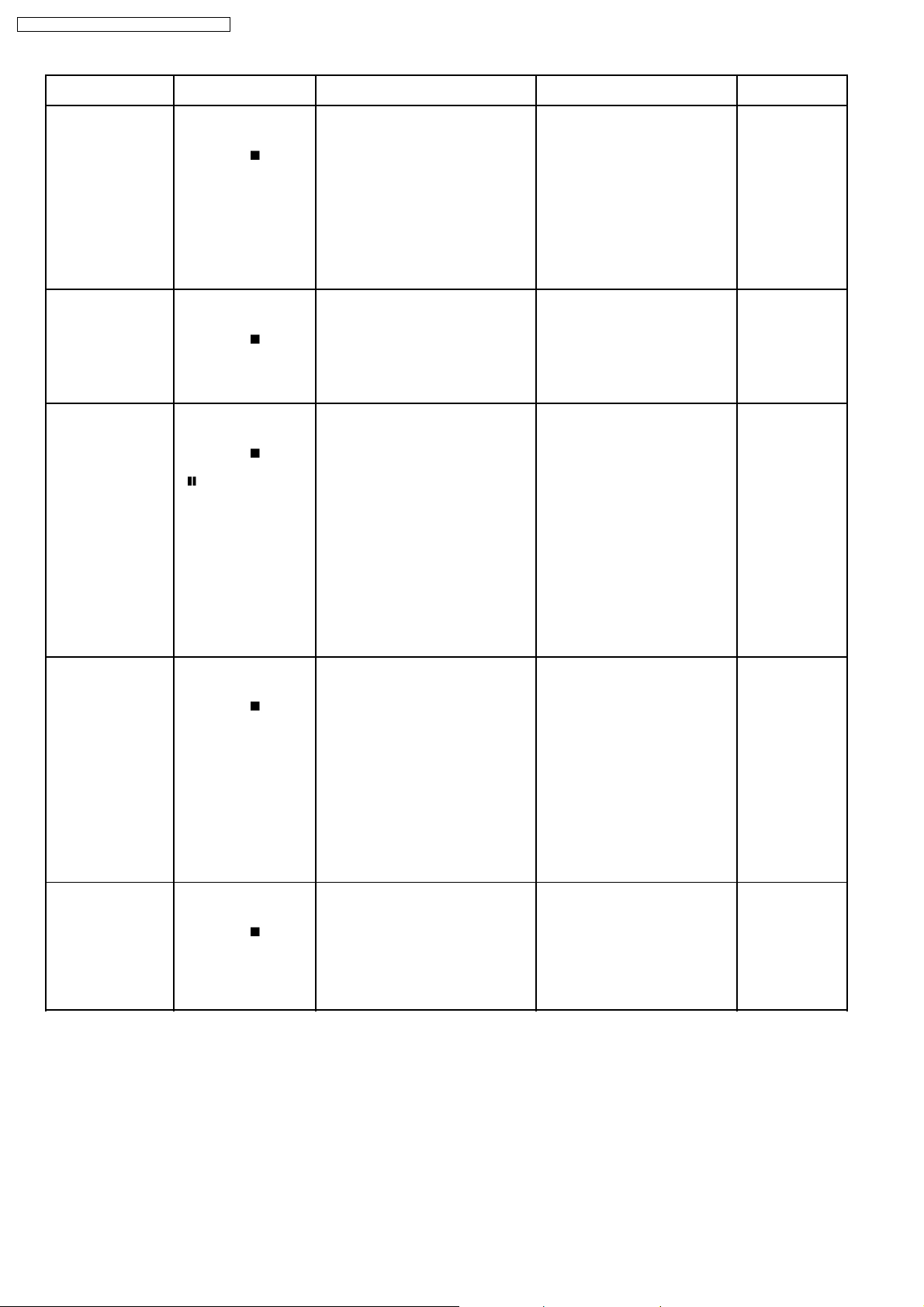
15.6. Mode Table 2
Following modes are available with combinations of the pressed buttons on the player and on the remote controller unit.
21
SA-VK82DGCP / SA-VK82DG CS / SA-VK82DGS
Item Operational Condition
and Key Function
Jitter display While the player is
stopped and no disc is
inserted, press and hold
down the
button
on the player and the
number button, “5” on
the remote controller
unit.
Error code display While the player is
stopped and no disc is
inserted, press and hold
down the
button
on the player and the
number button, “0” on
the remote controller
unit.
Measurement of laser
current electricity
initialization value
While the player is
stopped and no disc is
inserted, press and hold
down the
button
on the player and the
button on the
remote controller unit.
Press “FL Display”
button for next page
Details Display TO Exit Mode
Jitter display
Measures and displays jitter.
Measurement is repeated every
second. Read error counter starts at 0
at the mode setting, and increased by
one as data read fails at target block. A
small defect is allowed to correct by
retry. Any possibility is counted as one
increment. Repetitive errors after retry
increase by two levels or more.
Error code display
Displays the latest error code stored in
EEPROM.
Measurement of laser current
electricity initialization value
Memorizes each initialization value of
DVD and CD in EEPROM.
J*1xxx/yyy zz (display1/display2)
*1
: Jitter display mode
*2
: Jitter measurement value
*3
: Read error counter
*4
: Focus driving value
Values are shown to one decimal
place in the decimal digit. Focus
driving value is displayed in the
hexadecimal digit.
DVD_F---
*nn: Error history
*--: Error number
LDO*1/xxx*2yyyy
*3
(display1/display2)
*1
: Laser current electricity
measurement mode
*2
: DVD current electricity value
*3
: CD current electricity value
Press the STOP
button on the
player.
Press the STOP
button.
Automatically exits
the mode after five
seconds.
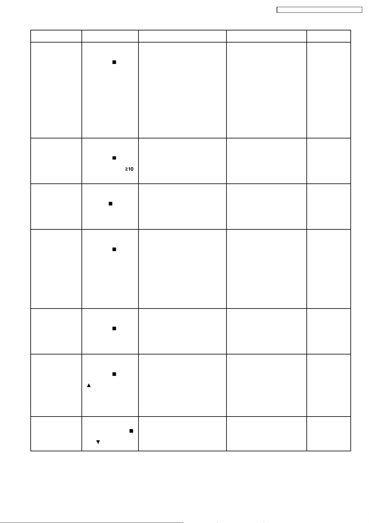
Measurement of DVD
laser current electricity
ADSC internal RAM
display
While the player is
stopped and no disc is
inserted, press and hold
down the
button
on the player and the
FUNCTIONS button on
the remote controller
unit.
Press “FL Display”
button for next page
While the player is
stopped and no disc is
inserted, press and hold
down the
button
on the player and the
number button “1” or “2”
on the remote controller
unit.
Measurement of DVD laser current
electricity
Measures DVD laser current electricity
and displays the result together with
the initialization value stored in
EEPROM. After measurement, DVD
laser is lit till the power is turned off (or
goes off when the primary power is
turned off).
ADSC internal RAM display
Reads and displays the RAM value
inside ADSC. The address is renewed
when the CLEAR key is pressed so
that the values at eleven points appear.
Values are shown in the decimal
digit. The above example indicates
that the current electricity
initialization value is 13mA at DVD
laser and 32mA at CD laser when
laser is turned on.
LDD*1/xxx*2yyyy
*3
(display1/display2)
*1
: DVD laser current electricity
measurement mode
*2
: Current electricity initialization
value stored in EEPROM
*3
: Present value of current
electricity
Values are shown in the decimal
digit. The above example indicates
that the current electricity
initialization value is 12mA and its
present value is 14mA.
FB0_0000
Values are shown in the
hexadecimal digit. The above
example indicates that ADSC
value at the address, FB0h is
0000h.
Automatically exits
the mode after five
seconds.
Press the STOP
button on the
player.
22
SA-VK82DGCP / SA-VK82DG CS / SA-VK82DGS
Item Operational Condition
and Key Function
Measurement of CD
laser current electricity
While the player is
stopped and no disc is
inserted, press and hold
down the
button
on the player and the
number button “3” on the
remote controller unit.
Press “FL Display”
button for next page
User initialization While the player is
stopped and no disc is
inserted, press and hold
down the
button
on the player and the
number button
on the remote controller
unit.
Region display While the player is
stopped and no disc is
inserted, press and hold
down the
button on
the player and the
number button, “6” on
the remote controller
unit.
Firmware version
display
While the player is
stopped and no disc is
inserted, press and hold
down the
button
on the player and the
number button, “7” on
the remote controller
unit.
Details Display TO Exit Mode
Measurement of CD laser current
electricity
Measures CD laser current electricity
and displays the result together with
the initialization value stored in
EEPROM. After measurement, CD
laser is lit till the power is turned off (or
goes off when the primary power is
turned off).
LDC*1/xxx*2yyyy
(display1/display2)
*1
: CD laser current electricity
measurement mode
*2
: Current electricity initialization
value stored in EEPROM
*3
: Present value of current
electricity
Values are shown in the decimal
digit. The above example indicates
the current electricity initialization
value is 28mA and its present
value is 26mA when laser is turned
on.
User initialization
“INIT” Automatically exits
The user setting recovers the factory
setting.
Region display [s rr zzz]
s : Panecon model type
rr : Panecon release number
zzz: Syscon release number
Firmware version display rrr*1xx*2y*3zzz
*1
: Panel computer release number
*2
: System computer generation
*3
: System computer model type
*4
: System computer release
number
*3
Automatically exits
the mode after five
seconds.
the mode after five
seconds.
Automatically exits
the mode after five
seconds.
*4
Automatically exits
the mode after five
seconds.
Press “FL Display”
button for next page
Region and firmware
display
While the player is
stopped and no disc is
inserted, press and hold
down the
button
on the player and the
number button, “8” on
the remote controller
unit.
Laser use time While the player is
stopped and no disc is
inserted, press and hold
down the
button
on the player and the
button on the
remote controller unit.
Press “FL Display”
button for next page
Reset laser use time While the usage time 1 is
displayed, press and
hold down the
button on the player and
the
button on the
remote controller unit.
Region and firmware version display x*1y*2z*3w
*1
: Region number
*2
: System computer generation
*3
: System computer model type
*4
: System computer release
number
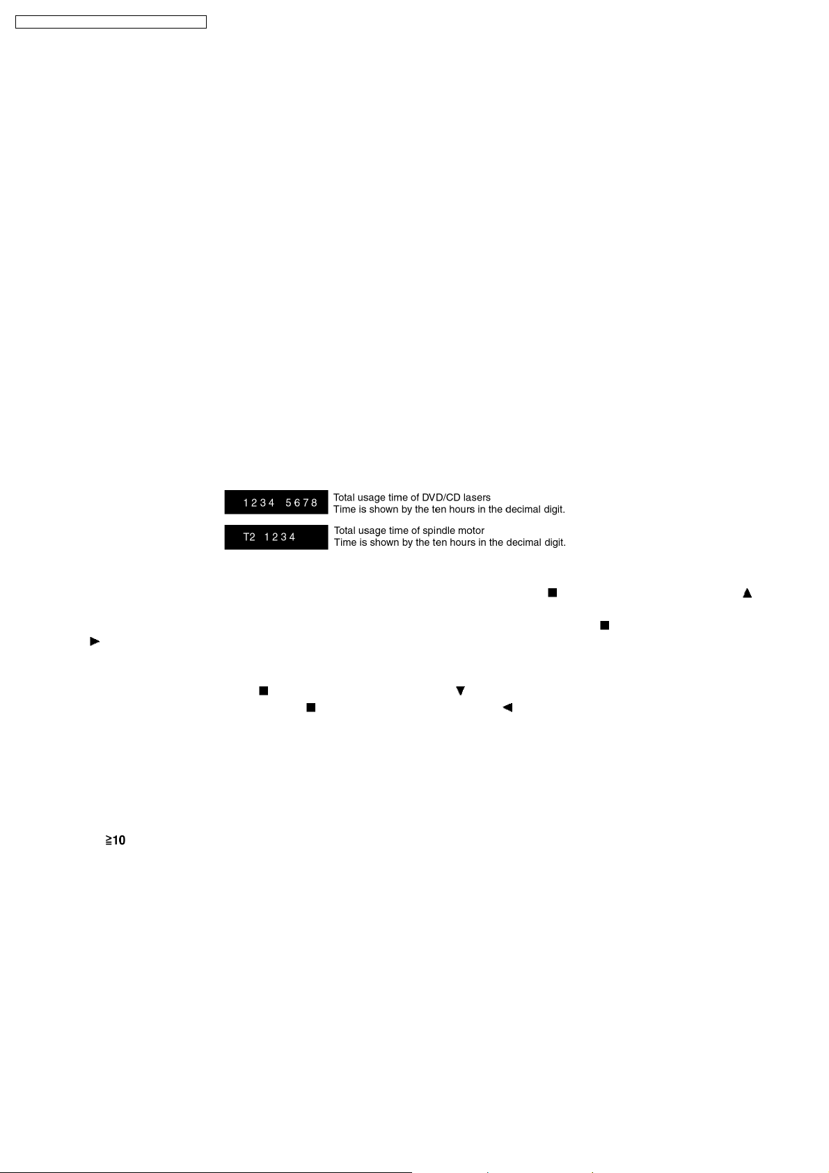
Laser usage time
Measures each for DVD and CD
T1_ _1234/5678
(display1/display2)
respectively.
The numbers in the left show
usage time for DVD laser and
those in the right for CD laser. The
four-digit number is shown by the
ten hours in the decimal digit. The
number after 0000 is 9999.
Laser usage time reset
Resets both for DVD and CD at once.
T1_ _0000/0000
(display1/display2)
*4
Automatically exits
the mode after five
seconds.
Automatically exits
the mode after five
seconds.
Automatically exits
the mode after five
seconds.
23
SA-VK82DGCP / SA-VK82DG CS / SA-VK82DGS
Item Operational Condition
Spindle use time While the player is
Reset spindle use
time
Communication error
display
and Key Function
stopped and no disc is
inserted, press and hold
down the
on the player and the
button on the
remote controller unit.
While the usage time 2 is
displayed, press and
hold down the
button on the player and
the
remote controller unit.
While the player is
stopped and no disc is
inserted, press and hold
down the
on the player and the
MENU button on the
remote controller unit.
Press “FL Display”
button for next page
button
button on the
button
Spindle motor usage time T2_00000
Usage time 2 reset
Spindle motor usage time
Displays frequency of communication
errors between system computer firm
IC and mechanical computer IC during
DVD module.
Details Display TO Exit Mode
Automatically exits
The four-digit number is shown by
the ten hours in the decimal digit.
The number after 00000 is 99999.
T2_ _00000 Automatically exits
ECC_ _ _ 00 Press the STOP or
the mode after five
seconds.
the mode after five
seconds.
Open button on the
player.
15.7. CR16 Mechanism Ageing Mode
To perform the ageing mode:
1. Enter into Test mode.
2. Press [3] button on remote control. It enters into ageing mode. (see below for ageing process)
Ageing process:
1. Tray 1 open.
2. It waits for one second (Note: Do not put any disc into the tray.
3. Tray close.
4. TOC READ (Reading incomplete)
5. Tray 2 open & repeat step 1 to step 4. (Process repeat until Tray 5)
6. Tray check.
7. Whole process complete (Counter on FL increase by 1)
Note: To exit ageing mode, press [POWER] button. The unit will power down. Do not unplug the power cord until FL display shows
“GOODBYE”. This is to avoid tray jam problem.
15.8. Operation Lock Function
15.8.1. Setting
· Operation Lock Function
1. With the DVD/CD/
Lock mode B.
[_LOCKED_] will be display ed for 3 seconds, and the current disc will begin playing.
2. Lock mode B primarily controls the selector and disc operations, and disena bles for the following keys.
Note:
OPEN/CLOSE
· Prohibiting operation of selector and disk
1. Select the DVD/CD/
2. Press and hold down the DVD/CD/
three seconds. (The message, “_LOCKED_” appears when the function is activated.)
Note:
The following buttons are invalid and the player displays “_LOCKED_” while the lock function mode is entered.
and POWER ON, and then press the [POWER] KEY on the remote control for 3 seconds to enter
button are invalid and the player displays “_LOCKED_” while the lock function mode is entered.
function.
button on the player and the power button on the remote controller unit for at least
24
15.9. Things to Do After Repair
Follow the procedure described below after repair.
1. While the power is on, press the
2. Press the power button to turn off the power.
3. Unplug the power cable.
Note:
It is prohibited to unplug the power cable while the tray is opened and to close the tray manually.
button to close the tray.
SA-VK82DGCP / SA-VK82DG CS / SA-VK82DGS
16 Cautions To Be Taken During Servicing
16.1. Recovery after the dvd player is repaired
· W hen Flash ROM or DVD Module P.C.B. is replaced, carry out the recovery processing to optimize the drive. Playback the
recovery disc to process the recovery automatically.
· Recovery disc (Product number=RFKZD03R005)
· Performing recovery
1. Load the recovery disc (Product number: RFKZD03R005) to the player and run it.
2. Recovery is performed automatically. When it is finished, a message appears on the screen.
3. Remove the recovery disc.
4. Turn off the power.
16.2. DVD Player Firmware Version Upgrade Process
Firmware of DVD player may upgrade to conform to improvement of its performance and quality includi ng operational range,
playability of non-standardized discs, etc. The version upgrade disc contains the recovery function, and the recovery disc is not
necessary.
Note:
Version upgrade process cannot be complete if the AC power is cut off due to power failure and other occasions during the
process. If this occurs, replace FLASH ROM IC and restart version upgrade. Version upgrade disc number is informed when
ordered.
16.3. Firmware Version Upgrade Process by Using Disc and Recovery
Process
· Recovery process
· Firmware version upgrade process
Both of the above procedures automatically start when the recovery disc is replayed.General CD-R disc allows version upgrade
process and recovery process, making version upgrade through disc simple.
Recovery process: Optimization process of player after replacement of FLASH ROM, EEPROM, or module circuit board
25
SA-VK82DGCP / SA-VK82DG CS / SA-VK82DGS
Version upgrade process: Renewal of firmware for improvement of operational range and performance
16.4. Using Recovery Disc
16.4.1. Recovery Process
1. Insert the recovery disc (RFKZD03R005) to the player to replay.
2. The recovery process automatically starts, and a message of completion prompts on the screen.
3. Remove the disc.
4. Turn off the power.
16.4.2. Version Upgrade Process
1. Insert the recovery disc to the player to replay.
2. The version of player is automatically checked and prompts if necessary.
3. Select version upgrade process using the cursor keys on the remote controller unit. (Select YES or NO)
4. a. If YES is selected, the process starts.
b. If NO is selected, only the recovery process is applied .
5. a. When the version upgrade process is complete, a message of completion appears on the screen. Remove the disc.
b. Follow the instruction appearing on the screen, and remove the disc.
6. Turn off the power.
16.5. Total Usage Time Display
1. Details of Operation/Display
Keys for Operation:
Laser usage time: While the player is stopped and no disc is inserted, press both the
button on the remote controller unit.
Spindle motor usage time: While the player is stopped and no disc is inserted, press both the
the
To reset the usage time, while the usage time is displayed:
Laser usage time: press both the
Spindle motor usage time: press both the
2. Purpose of Use
To obtain reference data of laser and spindle motor systems during failure diagnosis.
To check faulty parts during re-repair.
button on the remote controller unit.
button on the player and the button on the remote controller unit.
button on the player and the button on the remote controller unit.
16.6. After replacement of DVD Module
Below steps is to be performed after changing of DVD Module
1. Press
2. FL will display “INITIALIZE”.
3. Press “STOP” & “ENTER” on remote control (For reset of unit)
4. FL will display “DVD RESET” before change to TOC reading again.
5. Power off the set. Unplug AC cord & wait for few seconds.
6. Plug in AC cord & power on set.
on remote control while pressing “STOP” on main unit.
button on the player and the
button on the player and
26

SA-VK82DGCP / SA-VK82DG CS / SA-VK82DGS
17 Disassembly and Assembly of Main Component
“ATTENTION SERVICER”
Some chassis components may have sharp edges. Be careful when disassembling and servicing.
1. This section describes procedures for checking the operation of the major printed circuit boards and replacing the main
components.
2. For reassembly after operation checks or replacement, reverse the respective procedures.
Special reassembly procedures are described only when required.
3. Select items from the following index when checks or replacement are required.
4. Refer to the Parts No. on the page of “Parts Location and Replacement Parts List” (Section 27), if necessary.
17.1. Disassembly steps
· Disasse mbly of Top Cabinet
· Disasse mbly of Rear Panel
· Disasse mbly of DVD Changer Unit
· Disasse mbly of Main P.C.B.
· Disasse mbly of Power Amp P.C.B.
· Disasse mbly of Power P.C.B.
· Disasse mbly of Transformer P.C.B. & Voltage Selector
· Disasse mbly of Front Panel Unit
· Disasse mbly of Mic P.C.B. & Panel P.C.B.
· Disasse mbly of Deck Mechanism Unit
· Replacement for Deck P.C.B.
· Replacement for Traverse Deck
· Replacement for Optical Pickup Unit (DVD Mechanism)
· Procedure for removing CD loading mechanism
· CR16 mechanism disassembly procedure
· CR16 mechanism assembly procedure
· Disasse mbly for Traverse Unit
· Replacement for cassette lid
· Rectification for tape jam problem
27
SA-VK82DGCP / SA-VK82DG CS / SA-VK82DGS
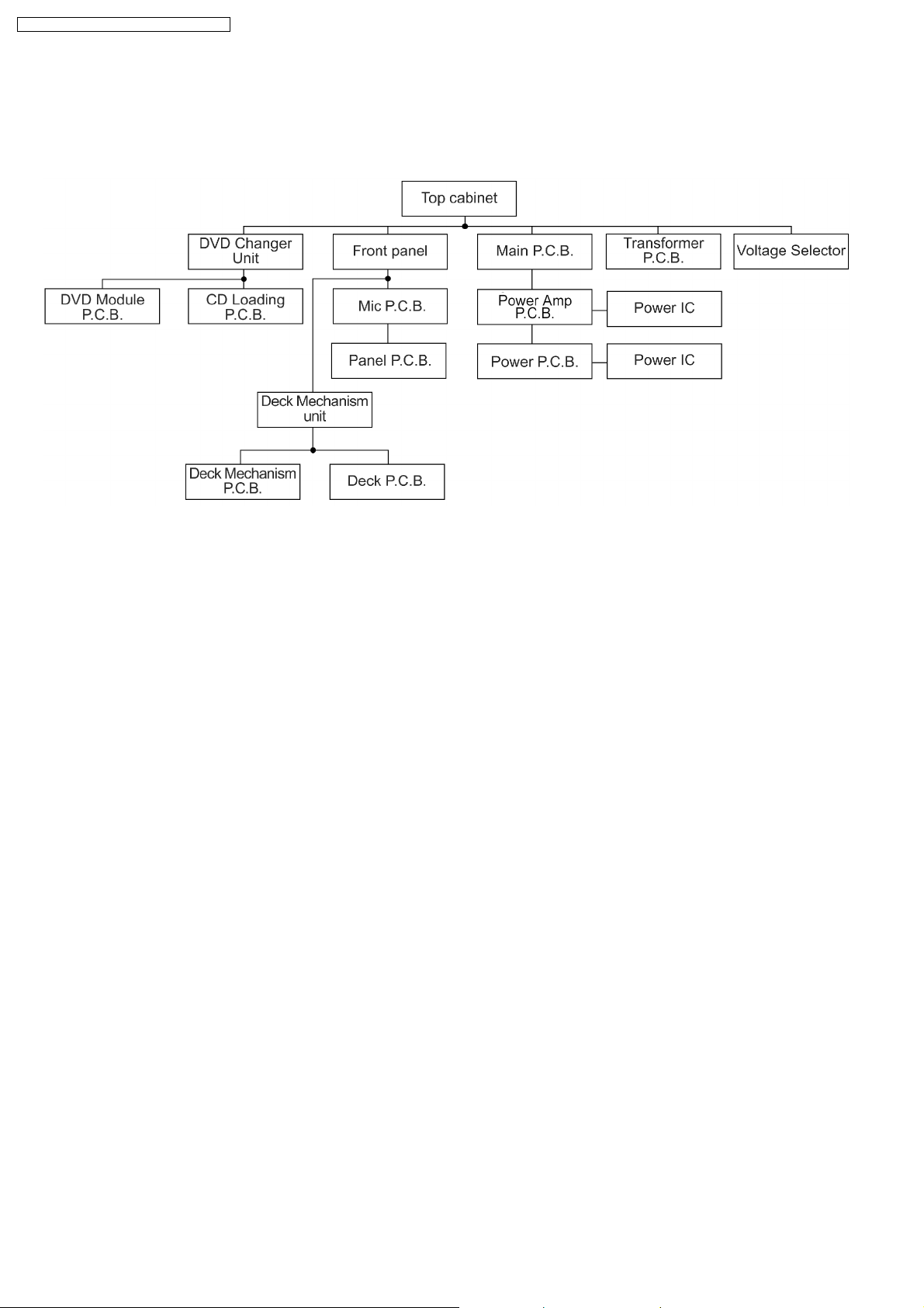
17.2. Disassembly flow chart
The following chart is the procedure for disassembling the casing and inside parts for internal inspection when carrying out the
servicing.
To assemble the unit, reverse the steps shown in the chart as below.
28
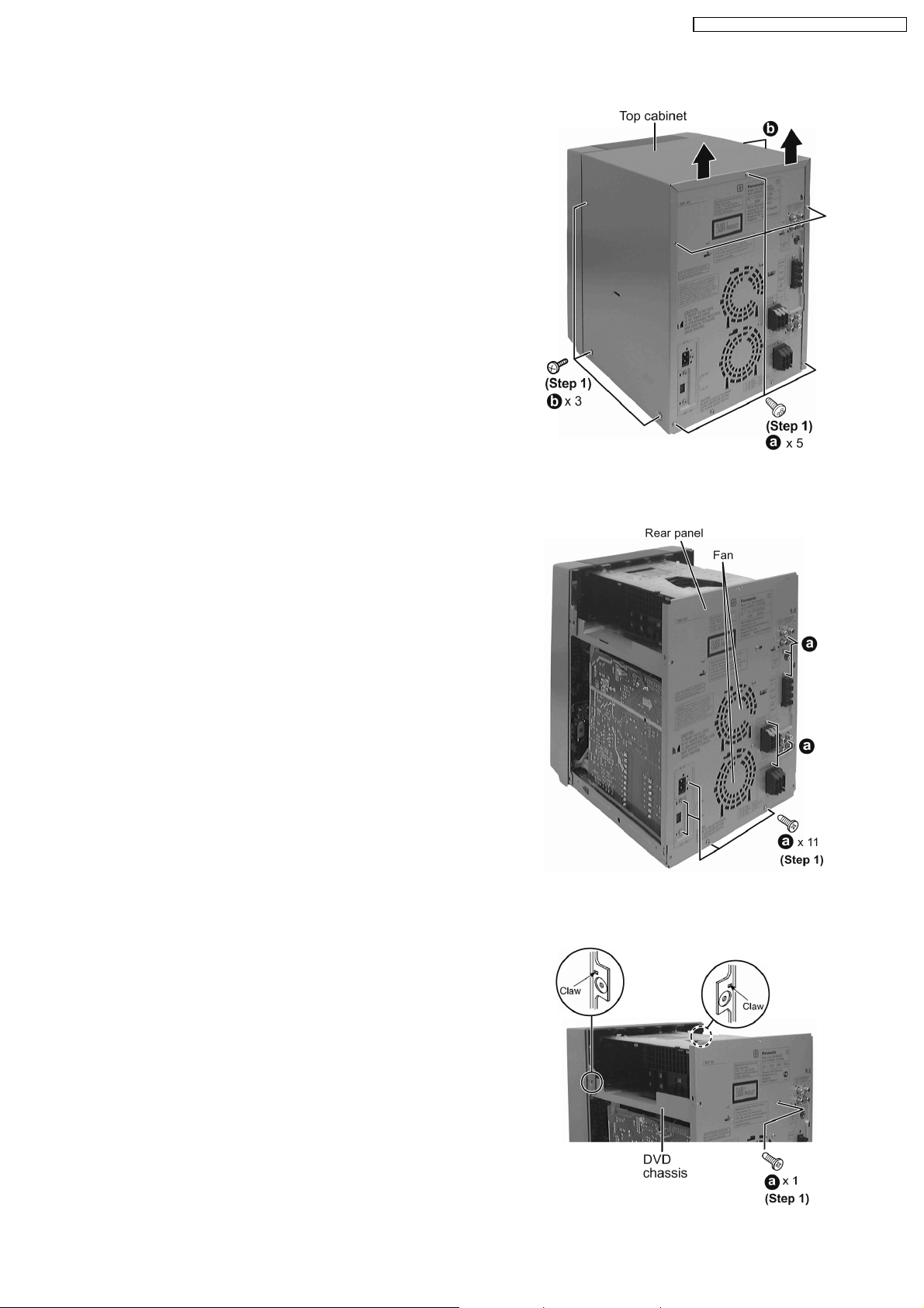
17.3. Disassembly of Top Cabinet
Step 1 Remove 3 screws at each side and 5 screws at rear
panel.
Step 2 Lift up both sides of the top cabine t, push the top
cabinet towards the rear to remove the top cabinet.
SA-VK82DGCP / SA-VK82DG CS / SA-VK82DGS
17.4. Disassembly of Rear Panel
· Follow the (Step 1) - (Step 2) of Item 17.3 - Disassembly of Top Cabinet
Step 1 Remove 11 screws and disconnect cables CN2810 and
CN2813 (Fan) at rear panel as shown.
17.5. Disassembly of DVD Changer Unit
· Follow the (Step 1) - (Step 2) of Item 17.3 - Disassembly of Top Cabinet
Step 1 Remove 1 screw at rear panel.
29
SA-VK82DGCP / SA-VK82DG CS / SA-VK82DGS
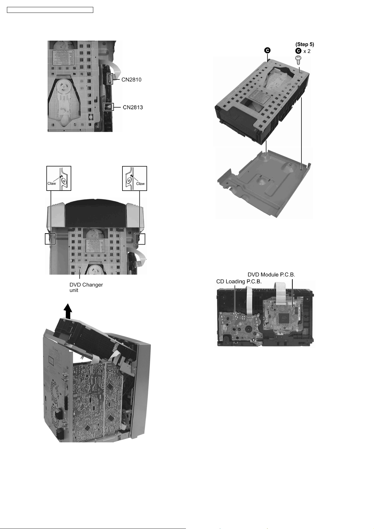
Step 2 Detach the FFC cables (CN2810 & CN2813).
Step 3 Release the claws on both ends, and remove the DVD
changer unit.
Step 4 Lift the DVD changer unit upwards.
Step 5 Remove 2 screws.
Step 6 Remove the DVD chassis.
Step 7 Lay the unit.
· For disassembly of DVD mechanism unit, please refer to
Section 17.16 of this manual.
17.6. Disassembly of Main P.C.B.
· Follow the (Step 1) - (Step 2) of Item 17.3 - Disassembly of Top Cabinet
· Follow the (Step 1) of Item 17.4 - Disassembly of Rear Panel
· Follow the (Step 1) - (Step 4) of Item 17.5 - Disassembly of DVD Changer Unit
30
 Loading...