

Page 1
A
A
ORDER NO. MD0704019CE
DVD Home Theater Sound System
SA-PTX7EB
SA-PTX7EG
Colour
(K).......................Black Type
Specifications
!
!GENERAL
!!
Power Supply:
Power Consumption: 90 W
Power Consumption in Standby Mode:
Power-Save Mode (Shipping Condition) Approx. 0.6 W
Dimensions (W×H×D): 360×105.5×334 mm
Mass:
(Dimensions and Mass do not include the speakers.)
Operating Temperature Range: +5°C to +40°C
Operating Humidity Range: 10% to 80% RH (no
!
!AMPLIFIER SECTION
!!
Dolby Virtual Speaker Mode (RMS)
Total Power Output: 300 W
At 1 kHz and total harmonic of 10%
!
!Front Ch: 50 W / Channel (8 Ω)
!!
!
!Center Ch: 50 W / Channel (8 Ω)
!!
At 100 Hz and total harmonic of 10%
!
!Subwoofer Ch: 100 W / Channel (4 Ω )
!!
Dolby Virtual Speaker Mode (DIN)
Total Power Output: 210 W
At 1 kHz and total harmonic of 1%
!
!Front Ch: (both CH driven)
!!
C 230 V - 240 V, 50 Hz
pprox. 4.7 kg
condensation)
35 W / Channel (8 Ω)
!
!Center Ch: (both CH driven)
!!
35 W / Channel (8 Ω)
At 100 Hz and total harmonic of 1%
!
!Subwoofer Ch: 70 W / Channel (4Ω)
!!
Dolby Virtual Speaker Mode (2.1 ch DIN)
Total Power Output: 140 W
At 1 kHz and total harmonic of 1%
!
!Front Ch: (both CH driven)
!!
35 W / Channel (8 Ω)
At 100 Hz and total harmonic of 1%
!
!Subwoofer Ch: 70 W / Channel (4Ω)
!!
!
!FM TUNER SECTION
!!
Frequency range: 87.50-108.00 MHz
(50 kHz step)
Antenna terminals: 75 Ω (unbalanced)
!
!HDD SECTION:
!!
Internal HDD Capacity: 80 GB
Recording Format: AAC/Linear PCM
MP3/WMA (LAN-PC)
Bit Rate (AAC): 128 kbps (XP)/96 kbps (SP)/
64 kbps (LP)
Channel: 2 channels (stereo)
Recording Time:
!
!AAC: Approx. 2460 hours (LP mode)
!!
© 2007 Matsushita Electric Industrial Co., Ltd. All
rights reserved. Unauthorized copying and
distribution is a violation of law.
Page 2
SA-PTX7EB / SA-PTX7EG
!
!Linear PCM: Approx. 104 hours
!!
!
!DIGITAL AUDIO OUTPUT:
!!
Optical Digital Output: Optical terminal (up to 96 kHz)
!
!DIGITAL AUDIO INPUT:
!!
Optical Digital Input: Optical terminal (up to 48 kHz)
!
!DISC SECTION
!!
Playable discs [8 cm or 12 cm]:
(1) DVD [DVD-Video, DVD-Audio, DivX (*6, *7)]
(2) DVD-RAM [DVD-VR, MP3 (*2, *7), JPEG (*4, *7), MPEG4
(*5, *7), DivX (*6, *7)]
(3) DVD-R [DVD-VR, DVD-Video, MP3 (*2, *7), JPEG (*4, *7),
MPEG4 (*5, *7), DivX (*6, *7)]
(4) DVD-R DL [DVD-VR (*8), DVD-Video]
(5) DVD-RW [DVD-VR, DVD-Video, MP3 (*2, *7), JPEG (*4, *7),
MPEG4 (*5, *7), DivX (*6, *7)]
(6) +R/+RW (Video)
(7) +R DL (Video)
(8) CD, CD-R/RW [CD-DA, Video CD, SVCD (*1), MP3 (*2, *7),
WMA (*3, *7), JPEG (*4, *7), MPEG4 (*5, *7), DivX (*6, *7)
HighMAT Level 2 (Audio and Image)]
*1 Conforming to IEC62107
*2 MPEG-1 Layer 3, MPEG-2 Layer 3
*3 Windows Media Audio Ver.9.0 L3
!Not compatible with Multiple Bit Rate (MBR)
*4 Exif Ver 2.1 JPEG Baseline files
!Picture resolution: between 160 x 120 and 6144 x 4096
pixels (Sub sampling is 4:2:2 or 4:2:0). Extremely long and
slender pictures may not be displayed.
*5 MPEG4 data recorded with the Panasonic SD multi cameras
or DVD video recorders.
!Conforming to SD VIDEO specifications (ASF standard)/
MPEG4 (Simple Profile) video system/G.726 audio system.
*6 Plays all versions of DivX® video (including DivX®6) with
standard playback of DivX® media files. Certified to the DivX
Home Theater Profile.
*7 The total combined maximum number of recognizable audio,
picture and video contents and groups: 4000 audio, picture
and video contents and 400 groups.
*8 Discs recorded on DVD recorders or DVD cameras using
Version 1.2 of the Video Recording Format (a unified video
recording standard).
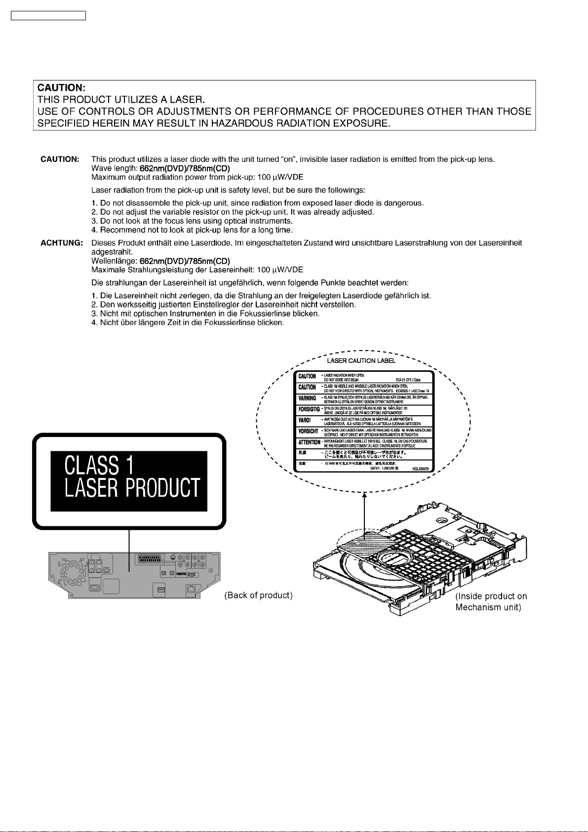
Pick Up:
Wavelength:
!
!CD: 785 nm
!!
!
!DVD: 662 nm
!!
Laser power:
!
!CD / DVD: CLASS 1M / CLASS 1
!!
!
!VIDEO SECTION
!!
Video System: PAL 625/50, PAL 525/60,
NTSC
Video Output:
!
!Output level: 1 Vp-p (75 Ω)
!!
!
!Output Terminal:
!!
Pin jack (1 system)/Scart jack (1 system)
S-video Output:
!
!Y output level: 1 Vp-p (75 Ω)
!!
!
!C output level: NTSC; 0.286 Vp-p (75 Ω)
!!
PAL; 0.300 Vp-p (75 Ω)
!
!Output Terminal:
!!
S terminal (1 system)/Scart jack (1 system)
Component Video Output (480p/480i):
!
!Y output level: 1 Vp-p (75 Ω)
!!
!
!PBoutput level: 0.7 Vp-p (75 Ω)
!!
!
!PRoutput level: 0.7 Vp-p (75 Ω)
!!
!
!Output Terminal: Pin jack (Y: green, PB: blue,
!!
P
: red) (1 system)
R
RGB Video Output:
!
!R output level: 0.7 Vp-p (75 Ω)
!!
!
!G output level: 0.7 Vp-p (75 Ω)
!!
!
!B output level: 0.7 Vp-p (75 Ω)
!!
!
!Output Terminal: Scart jack (1 system)
!!
HDMI AV Output: HDMI 19 pin type A connector
This unit supports “HDAVI Control 2” function.
Note:
1. Specifications are subject to change without notice.
Mass and dimensions are approximate.
2. Total harmonic distortion is measured by the digital spectrum
analyzer.
Solder:
This model uses lead free solder (PbF).
Mechanism:
This model uses DL2S (Single tray) mechanism.
Refer to the respective original service manuals for *1, *2.
2
Page 3
SA-PTX7EB / SA-PTX7EG
3
Page 4
SA-PTX7EB / SA-PTX7EG
CONTENTS
Page Page
1 Safety Precautions 6
1.1. GENERAL GUIDELINES
1.2. Before Repair and Adjustment
1.3. Protection Circuitry
1.4. Safety Parts Information
1.5. Caution for AC Cord
2 Prevention of Electro Static Discharge (ESD) to
Electrostatically Sensitive (ES) Devices
3 Precaution of Laser Diode
4 About Lead Free Solder (PbF)
4.1. Service caution based on legal restrictions
5 Handling Precautions for Traverse Unit
5.1. Cautions to Be Taken in Handling the Optical Pickup Unit
5.2. Grounding for electrostatic breakdown prevention
6 HDD (Hard Disk Drive) Handling Care
7 Accessories
8 Operation Procedures
8.1. Remote Control Key Buttons Operations
8.2. Main Unit Key Buttons Operations
8.3. Using the EZ Sync HDAVI Control
8.4. Using the Music Port
8.5. Using the iPod
8.6. Disc Information
9 New Features
9.1. As a Music Jukebox (Using HDD)
9.2. Easy Location of HDD Recording Contents
9.3. Network Connections (LAN)
9.4. Operating iPod with this Unit
10 Self-D iagno sis and Special Mode Setting
10.1. Service Mode Summary Table
10.2. Service Mode Table (Main Unit)
10.3. DVD Self Diagnostic Function-Error Code
10.4. Sales Demonstration Lock Function
10.5. Service Precautions
11 Assem bling and Disassemb l in g
11.1. Disassembly Flow Chart
11.2. Main Components and P.C.B. Locations
11.3. Disassembly of Top Cover Assembly
11.4. Disassembly of Top Shield
11.5. Disassembly of Front Panel
11.6. Disassembly of Panel P.C.B., Tact-1 P.C.B. & Tact-2
P.C.B.
11.7. Disassembly of USB P.C.B.
11.8. Disassembly of Main P.C.B.
10
11
11
12
12
12
14
15
16
16
17
18
20
21
22
24
24
30
32
38
39
39
39
48
51
52
53
54
55
56
56
56
57
58
58
6
6
6
7
8
9
11.9. Disassembly of Power P.C.B.
11.10. Replacement of Regulator IC (IC725)
11.11. Replacement of Regulator Diode (D725/D758)
11.12. Disassembly of Regulator P.C.B.
11.13. Disassembly of DVD Module P.C.B
11.14. Disassembly of Audio P.C.B.
11.15. Replacement of Digital Amp IC (IC102)
11.16. Replacement of Regulator Transistor (Q113)
11.17. Disassembly of DVD Mechanism Unit
11.18. Disassembly of Relay P.C.B.
11.19. Disassembly of Rear Panel
11.20. Disassembly of D-Port P.C.B.
11.21. Disassembly of Digital P.C.B.
11.22. Disassembly of AC-Inlet P.C.B.
11.23. Disassembly of Hard Disk Drive (HDD)
12 Assemb ly and disassembly of DVD Mecha n ism Unit
12.1. Disassembly Procedure
13 Service Fixture and Tools
14 Service Positions
14.1. Checking & Repairing Main P.C.B.
14.2. Checking & Repairing DVD Module P.C.B.
14.3. Checking & Repairing Audio P.C.B.
14.4. Checking & Repairing Regulator P.C.B.
14.5. Checking & Repairing Power P.C.B.
14.6. Checking & Repairing Panel P.C.B.
14.7. Checking & Repairing Digital P.C.B.
14.8. Checking & Repairing AC-Inlet P.C.B.
15 Measurements and Adjustments
15.1. Service Tools and Equipment
15.2. Important points in adjustment
15.3. Storing and handling of test discs
15.4. Optical adjustment
16 Abbreviations
17 Vol tage and Waveform Chart
17.1. DVD Module P.C.B.
17.2. Digital P.C.B.
17.3. Tray Loading, Panel, Tact-2 P.C.B.
17.4. Main P.C.B.
17.5. AC-Inlet, Power & Regulator P.C.B.
17.6. Audio (D-Amp) P.C.B.
17.7. Audio (DSP) P.C.B.
17.8. Waveform Chart
18 Illustration of IC’s, Trans istors and Diodes
19 Wiring Connection Diagram
20 Block Diagram
59
60
60
61
61
62
63
63
64
64
64
66
66
68
68
69
69
74
74
74
75
75
77
77
77
78
80
82
82
82
82
83
84
86
86
89
91
92
94
95
96
98
101
103
105
4
Page 5

SA-PTX7EB / SA-PTX7EG
20.1. System Control 105
20.2. DVD (Servo)
20.3. DVD (Audio)
20.4. DVD (Video)
20.5. DVD (Interface)
20.6. AUDIO SELECTOR
20.7. AUDIO (DSP)
20.8. AUDIO DiGITAL AMP
20.9. DIGITAL 1
20.10. DIGITAL 2
20.11. POWER
21 Schem atic Diagram Notes
22 Schematic Diagram
22.1. DVD Module (DV5/HDMI/FPGA/VIDEO DAC) Circuit
22.2. Digital Circuit
22.3. Main, D-Port & Panel Circuit
22.4. Power, Audio (DSP/D-Amp), AC-Inlet & Regulator Circuit
22.5. Tact-1, Tact-2, USB, Relay, Tray Loading & Optical Pickup
Unit Circuit
23 Prin ted Circui t Board
23.1. DVD Module P.C.B.
23.2. Digital P.C.B.
23.3. Main P.C.B.
23.4. Panel, D-Port, Tact-1 & Tact -2 P.C.B.
106
107
108
109
110
111
112
113
114
115
117
119
119
127
133
138
146
149
149
150
151
153
23.5. Power & USB P.CB.
23.6. Audio (D-Amp/DSP) P.C.B.
23.7. AC-Inlet, Regulator, Relay & Tray Loading P.C.B.
24 Basic Troubleshooting Guide
24.1. Before Repairing
24.2. Precaution of Replacement of HDD (Hardisk)
24.3. Precaution of Repairing Digital P.C.B.
24.4. Troubleshooting Flowchart of HDD Unit, CD Drive Unit &
Main Micron (IC1502)
25 Terminal Function of ICs
25.1. IC501 (RFKWERE010EA): IC System Control
25.2. IC800 (C0HBB0000057): IC FL Display Driver
25.3. IC1101 (C1CB00002054): IC LAN (Ethermet Controller)
25.4. IC1200 (C1DB00001549): IC Link/Transaction Controller
25.5. IC1502 (C2GBC0000300): IC Microcomputer
25.6. IC1800 (MN677382FV): IC Sub Microprocessor
25.7. IC3201 (C1AB00002259): IC Video Encoder
26 Expl od ed Views
26.1. Cabinet Parts Location
26.2. Packaging
27 Repl acement Parts List
27.1. Component Parts List
28 Schem atic Diagram for printing with letter size
154
155
156
157
157
157
157
158
159
159
160
160
161
162
164
165
167
169
173
175
176
199
5
Page 6
SA-PTX7EB / SA-PTX7EG
1 Safety Precautions
1.1. GENERAL GUIDELINES
1. When servicing, observe the original lead dress. If a short circuit is found, replace all parts which have been overheated or
damaged by the short circuit.
2. After servicing, see to it that all the protective devices such as insulation barriers, insulation papers shields are properly
installed.
3. After servicing, carry out the following leakage current checks to prevent the customer from being exposed to shock hazards.
1.1.1. LEAKAGE CURRENT COLD CHECK
1. Unplug the AC cord and connect a jumper between the two prongs on the plug.
2. Measure the resistance value, with an ohmmeter, between the jumpered AC plug and each exposed metallic cabinet part on
the equipment such as screwheads, connectors, control shafts, etc. When the exposed metallic part has a return path to the
chassis, the reading should be between 1MΩ and 5.2MΩ.
When the exposed metal does not have a return path to the chassis, the reading must be
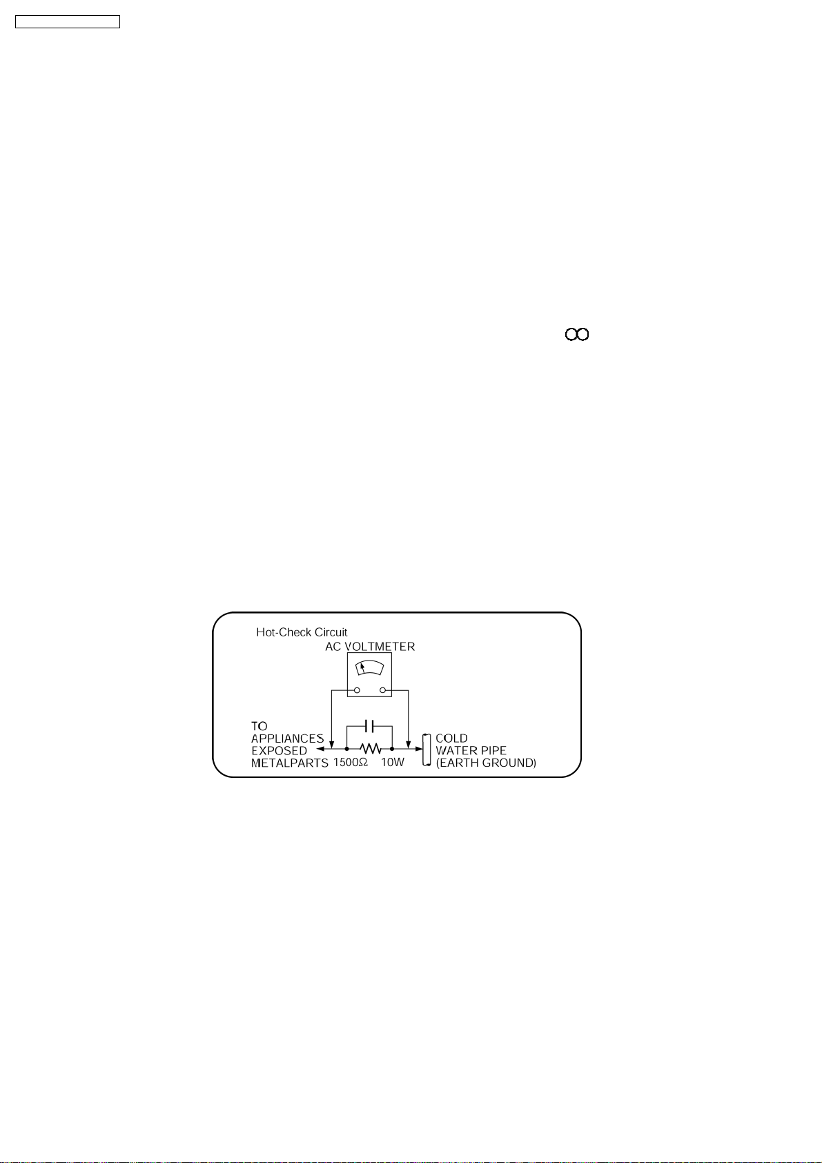
1.1.2. LEAKAGE CURRENT HOT CHECK
1. Plug the AC cord directly into the AC outlet. Do not use an isolation transformer for this check.
2. Connect a 1.5kΩ , 10 watts resistor, in parallel with a 0.15µF capacitors, between each exposed metallic part on the set and a
good earth ground such as a water pipe, as shown in Figure 1.
3. Use an AC voltmeter, with 1000 ohms/volt or more sensitivity, to measure the potential across the resistor.
4. Check each exposed metallic part, and measure the voltage at each point.
5. Reverse the AC plug in the AC outlet and repeat each of the above measurements.
6. The potential at any point should not exceed 0.75 volts RMS. A leakage current tester (Simpson Model 229 or equivalent) may
be used to make the hot checks, leakage current must not exceed 1/2 milliamp. In case a measurement is outside of the limits
specified, there is a possibility of a shock hazard, and the equipment should be repaired and rechecked before it is returned to
the customer.
Figure 1
1.2. Before Repair and Adjustment
Disconnect AC power to discharge unit AC Capacitors as such C701, C702, C703, C704, C705, C706, C707, C748 through a 10
Ω, 10 W resistor to ground.
Caution:
DO NOT SHORT-CIRCUIT DIRECTLY (with a screwdriver blade, for instance), as this may destroy solid state devices.
After repairs are completed, restore power gradually using a variac, to avoid overcurrent.
Current consumption at AC 240 V, 50 Hz in NO SIGNAL mode volume minimal should be ~ 600 mA.
1.3. Protection Circuitry
The protection circuitry may have operated if either of the following conditions are noticed:
•
• No sound is heard when the power is turned on.
• •
•
• Sound stops during a performance.
• •
The function of this circuitry is to prevent circuitry damage if, for example, the positive and negative speaker connection wires are
6
Page 7
SA-PTX7EB / SA-PTX7EG
“shorted”, or if speaker systems with an impedance less than the indicated rated impedance of the amplifier are used.
If this occurs, follow the procedure outlines below:
1. Turn off the power.
2. Determine the cause of the problem and correct it.
3. Turn on the power once again after one minute.
Note:
When the protection circuitry functions, the unit will not operate unless the power is first turned off and then on again.
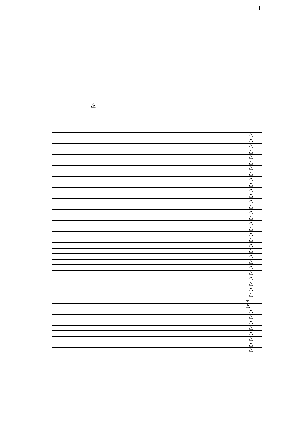
1.4. Safety Parts Information
Safety Parts List:
There are special components used in this equipment which are important for safety.
These parts are marked by
should be replaced with manufacturer’s specified parts to prevent shock, fire or other hazards. Do not modify the original design
without permission of manufacturer.
Reference No. Part No. Part Name & Description Remarks
340 RAE2025Z-S TRAVERSE UNIT [M]
PC701 B3PBA0000402 PHOTO COUPLER [M]
PC721 B3PBA0000402 PHOTO COUPLER [M]
TH701 D4CAA5R10001 THERMISTOR [M]
TH721 D4CAC8R00002 THERMISTOR [M]
L701 ELF15N035AN LINE FILTER [M]
L702 ELF19H010A CHOKE COIL [M]
LB102 J0JKB0000020 EMI BEAD CORE [M]
LB103 J0JKB0000020 EMI BEAD CORE [M]
LB501 J0JBC0000015 CHIP INDUCTOR [M]
LB502 J0JBC0000015 CHIP INDUCTOR [M]
LB503 J0JBC0000015 CHIP INDUCTOR [M]
LB504 J0JBC0000015 CHIP INDUCTOR [M]
LB505 J0JBC0000015 CHIP INDUCTOR [M]
LB506 J0JBC0000015 CHIP INDUCTOR [M]
LB507 J0JBC0000015 CHIP INDUCTOR [M]
LB509 J0JBC0000015 CHIP INDUCTOR [M]
LB510 J0JBC0000015 CHIP INDUCTOR [M]
LB8701 J0JBC0000015 CHIP INDUCTOR [M]
T701 ETS19AB221AG TRANSFORMER [M]
T721 ETS35BC2K6AD TRANSFORMER [M]
T722 G4D1A0000117 SWITCHING TRANSFORMER [M]
Z701 ERZV10D471CS ZENER [M]
RY701 K6B1AEA00015 POWER RELAY [M]
F701 K5D202BK0005 FUSE 2A [M]
IP701 K5H302100004 FUSE PROTECTOR [M]
IP702 K5H2022A0011 FUSE PROTECTOR [M]
IP703 K5H302100004 FUSE PROTECTOR [M]
IP722 K5H7512A0010 FUSE PROTECTOR [M]
P701 K2AA2B000011 JACK AC INLET [M]
A2 K2CQ2CA00002 AC CORD [M] EG
A2 K2CT3CA00004 AC CORD [M] EB
C701 F1BAF1020020 1000P [M]
C702 F1BAF1020020 1000P [M]
C703 ECQU2A104MLC 0.1µF [M]
C704 ECQU2A104MLC 0.1µF [M]
C705 F1BAF471A013 470P [M]
C706 F1BAF471A013 470P [M]
C707 F1BAF1020020 1000P [M]
C748 F1BAF471A013 470P [M]
in the Schematic Diagrams & Replacement Parts List. It is essential that these critical parts
Table 1
7
Page 8
SA-PTX7EB / SA-PTX7EG
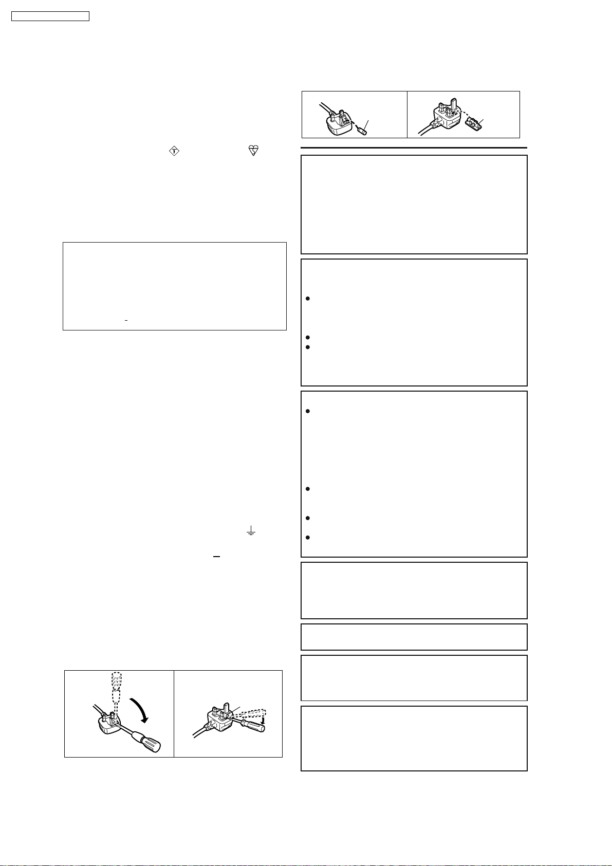
1.5. Caution for AC Cord
For your safety, please read the following text carefully.
This appliance is supplied with a moulded three pin
mains plug for your safety and convenience.
A 5-ampere fuse is fitted in this plug.
Should the fuse need to be replaced please ensure that
the replacement fuse has a rating of 5-ampere and that
it is approved by ASTA or BSI to BS1362.
Check for the ASTA mark or the BSI mark on the
body of the fuse.
If the plug contains a removable fuse cover you must
ensure that it is refitted when the fuse is replaced.
If you lose the fuse cover the plug must not be used
until a replacement cover is obtained.
A replacement fuse cover can be purchased from your
local dealer.
CAUTION!
IF THE FITTED MOULDED PLUG IS UNSUITABLE
FOR THE SOCKET OUTLET IN YOUR HOME THEN
THE FUSE SHOULD BE REMOVED AND THE
PLUG CUT OFF AND DISPOSED OF SAFELY.
THERE IS A DANGER OF SEVERE ELECTRICAL
SHOCK IF THE CUT OFF PLUG IS INSERTED
INTO ANY 13 AMPERE SOCKET.
If a new plug is to be fitted please observe the wiring
code as stated below.
If in any doubt please consult a qualified electrician.
IMPORTANT
The wires in this mains lead are coloured in accordance
with the following code:
Blue: Neutral, Brown: Live.
As these colours may not correspond with the coloured
markings identifying the terminals in your plug, proceed
as follows:
The wire which is coloured Blue must be connected to
the terminal which is marked with the letter N or
coloured Black or Blue.
The wire which is coloured Brown must be connected to
the terminal which is marked with the letter L or
coloured Brown or Red.
WARNING: DO NOT CONNECT EITHER WIRE TO
THE EARTH TERMINAL WHICH IS MARKED WITH
THE LETTER E, BY THE EARTH SYMBOL OR
COLOURED GREEN OR GREEN/YELLOW.
THIS PLUG IS NOT WATERPROOF KEEP DRY.
Before use
Remove the connector cover.
How to replace the fuse
The location of the fuse differ according to the type of
AC mains plug (figures A and B). Confirm the AC mains
plug fitted and follow the instructions below.
Illustrations may differ from actual AC mains plug.
A A
2. Replace the fuse and close or attach the fuse cover.
Figure A
Fuse
(5 ampere)
Figure B
Fuse
(5 ampere)
CAUTION!
THIS PRODUCT UTILIZES A LASER.
USE OF CONTROLS OR ADJUSTMENTS OR
PERFORMANCE OF PROCEDURES OTHER THAN
THOSE SPECIFIED HEREIN MAY RESULT IN
HAZARDOUS RADIATION EXPOSURE.
DO NOT OPEN COVERS AND DO NOT REPAIR
YOURSELF. REFER SERVICING TO QUALIFIED
PERSONNEL.
WARNING:
TO REDUCE THE RISK OF FIRE, ELECTRIC
SHOCK OR PRODUCT DAMAGE,
DO NOT EXPOSE THIS APPARATUS TO RAIN,
MOISTURE, DRIPPING OR SPLASHING AND THAT
NO OBJECTS FILLED WITH LIQUIDS, SUCH AS
VASES, SHALL BE PLACED ON THE APPARATUS.
USE ONLY THE RECOMMENDED ACCESSORIES.
DO NOT REMOVE THE COVER (OR BACK);
THERE ARE NO USER SERVICEABLE PARTS
INSIDE. REFER SERVICING TO QUALIFIED
SERVICE PERSONNEL.
CAUTION!
DO NOT INSTALL OR PLACE THIS UNIT IN A
BOOKCASE, BUILT-IN CABINET OR IN
ANOTHER CONFINED SPACE. ENSURE THE
UNIT IS WELL VENTILATED. TO PREVENT RISK
OF ELECTRIC SHOCK OR FIRE HAZARD DUE
TO OVERHEATING, ENSURE THAT CURTAINS
AND ANY OTHER MATERIALS DO NOT
OBSTRUCT THE VENTILATION VENTS.
DO NOT OBSTRUCT THE UNIT S VENTILATION
OPENINGS WITH NEWSPAPERS, TABLECLOTHS,
CURTAINS, AND SIMILAR ITEMS.
DO NOT PLACE SOURCES OF NAKED FLAMES,
SUCH AS LIGHTED CANDLES, ON THE UNIT.
DISPOSE OF BATTERIES IN AN
ENVIRONMENTALLY FRIENDLY MANNER.
CAUTION
Danger of explosion if battery is incorrectly replaced.
Replace only with the same or equivalent type
recommended by the manufacturer. Dispose of used
batteries according to the manufacturer s instructions.
THIS UNIT IS INTENDED FOR USE IN MODERATE
CLIMATES.
1. Open the fuse cover with a screwdriver.
Figure A Figure B
Fuse cover
This product may receive radio interference caused
by mobile telephones during use. If such interference
is apparent, please increase separation between the
product and the mobile telephone.
The socket outlet shall be installed near the
equipment and easily accessible. The mains plug of
the power supply cord shall remain readily operable.
To completely disconnect this apparatus from the AC
Mains, disconnect the power supply cord plug from
AC receptacle.
8
Page 9

SA-PTX7EB / SA-PTX7EG
2 Prevention of Electro Static Discharge (ESD) to
Electrostatically Sensitive (ES) Devices
Some semiconductor (solid state) devices can be damaged easily by static electricity. Such components commonly are called
Electrostatically Sensitive (ES) Devices. Examples of typical ES devices are integrated circuits and some field-effect transistors and
semiconductor "chip" components. The following techniques should be used to help reduce the incidence of component damage
caused by electro static discharge (ESD).
1. Immediately before handling any semiconductor component or semiconductor-equipped assembly, drain off any ESD on your
body by touching a known earth ground. Alternatively, obtain and wear a commercially available discharging ESD wrist strap,
which should be removed for potential shock reasons prior to applying power to the unit under test.
2. After removing an electrical assembly equipped with ES devices, place the assembly on a conductive surface such as
aluminum foil, to prevent electrostatic charge buildup or exposure of the assembly.
3. Use only a grounded-tip soldering iron to solder or unsolder ES devices.
4. Use only an anti-static solder removal device. Some solder removal devices not classified as "anti-static (ESD protected)" can
generate electrical charge sufficient to damage ES devices.
5. Do not use freon-propelled chemicals. These can generate electrical charges sufficient to damage ES devices.
6. Do not remove a replacement ES device from its protective package until immediately before you are ready to install it. (Most
replacement ES devices are packaged with leads electrically shorted together by conductive foam, aluminum foil or comparable
conductive material).
7. Immediately before removing the protective material from the leads of a replacement ES device, touch the protective material
to the chassis or circuit assembly into which the device will be installed.
Caution:
Be sure no power is applied to the chassis or circuit, and observe all other safety precautions.
8. Minimize bodily motions when handling unpackaged replacement ES devices. (Otherwise harmless motion such as the
brushing together of your clothes fabric or the lifting of your foot from a carpeted floor can generate static electricity (ESD)
sufficient to damage an ES device).
9
Page 10
SA-PTX7EB / SA-PTX7EG
3 Precaution of Laser Diode
10
Page 11
SA-PTX7EB / SA-PTX7EG
4 About Lead Free Solder (PbF)
4.1. Service caution based on legal restrictions
4.1.1. General description about Lead Free Solder (PbF)
The lead free solder has been used in the mounting process of all electrical components on the printed circuit boards used for this
equipment in considering the globally environmental conservation.
The normal solder is the alloy of tin (Sn) and lead (Pb). On the other hand, the lead free solder is the alloy mainly consists of tin
(Sn), silver (Ag) and Copper (Cu), and the melting point of the lead free solder is higher approx.30 degrees C (86°F) more than that
of the normal solder.
Definition of PCB Lead Free Solder being used
The letter of “PbF” is printed either foil side or components side on the PCB using the lead free solder.
(See right figure)
Service caution for repair work using Lead Free Solder (PbF)
•
• The lead free solder has to be used when repairing the equipment for which the lead free solder is used.
• •
(Definition: The letter of “PbF” is printed on the PCB using the lead free solder.)
•
• To put lead free solder, it should be well molten and mixed with the original lead free solder.
• •
•
• Remove the remaining lead free solder on the PCB cleanly for soldering of the new IC.
• •
•
• Since the melting point of the lead free solder is higher than that of the normal lead solder, it takes the longer time to melt
• •
the lead free solder.
•
• Use the soldering iron (more than 70W) equipped with the temperature control after setting the temperature at 350±30
• •
degrees C (662±86°F).
Recommended Lead Free Solder (Service Parts Route.)
•
• The following 3 types of lead free solder are available through the service parts route.
• •
RFKZ03D01K-----------(0.3mm 100g Reel)
RFKZ06D01K-----------(0.6mm 100g Reel)
RFKZ10D01K-----------(1.0mm 100g Reel)
Note
* Ingredient: tin (Sn), 96.5%, silver (Ag) 3.0%, Copper (Cu) 0.5%, Cobalt (Co) / Germanium (Ge) 0.1 to 0.3%
11
Page 12

SA-PTX7EB / SA-PTX7EG
5 Handling Precautions for Traverse Unit
The laser diode in the optical pickup unit may break down due to static electricity of clothes or human body. Special care must be
taken avoid caution to electrostatic breakdown when servicing and handling the laser diode.
5.1. Cautions to Be Taken in Handling the Optical Pickup Unit
The laser diode in the optical pickup unit may be damaged due to electrostatic discharge generating from clothes or human body.
Special care must be taken avoid caution to electrostatic discharge damage when servicing the laser diode.
1. Do not give a considerable shock to the optical pickup unit as it has an extremely high-precise structure.
2. To prevent the laser diode from the electrostatic discharge damage, the flexible cable of the optical pickup unit removed should
be short-circuited with a short pin or a clip.
3. The flexible cable may be cut off if an excessive force is applied to it. Use caution when handling the flexible cable.
4. The antistatic FPC is connected to the newoptical pickupunit. After replacing the optical pickup unit and connecting the flexible
cable, cut off the antistatic FPC.
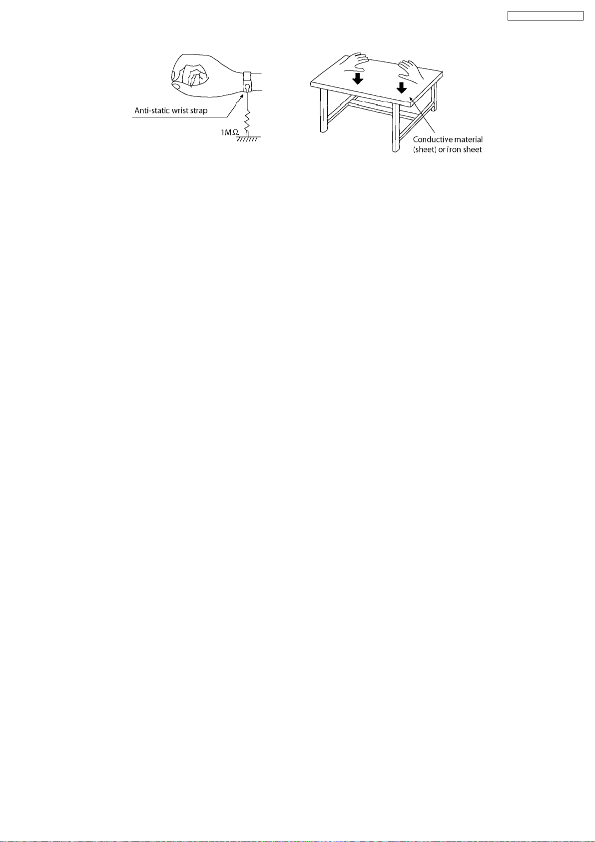
5.2. Grounding for electrostatic breakdown prevention
Some devices such as the DVD player use the optical pickup (laser diode) and the optical pickup will be damaged by static
electricity in the working environment. Proceed servicing works under the working environment where grounding works is
completed.
5.2.1. Worktable grounding
1. Put a conductive material (sheet) or iron sheet on the area where the optical pickup is placed, and ground the sheet.
5.2.2. Human body grounding
1. Use the anti-static wrist strap to discharge the static electricity form your body.
12
Page 13
SA-PTX7EB / SA-PTX7EG
13
Page 14
SA-PTX7EB / SA-PTX7EG
6 HDD (Hard Disk Drive) Handling Care
The HDD is a high precision recording instrument and because of its long recording capability and high speed operation it is a
very special device that is easily susceptible to damage.
The H
Depending on the setup environment and handling of the HDD some content may become damaged and play and recording may
no longer be possible. Especially during operation, do not subject the unit to any vibration, shock, or remove the AC mains lead
from the household AC mains socket . In the event of a power failure during recording or play, the content may be damaged.
Back up the HDD periodically
As a precaution for HDD failure, we recommend making a backup of the HDD periodically. However, in some cases where the
HDD is heavily damaged, backups may not be restored.
Immediately request service as soon as you feel there may be a problem with the HDD
If there is an irregularity within the HDD, repetitive strange sounds or distortion ("broken up" audio) may result. Using the HDD in
this condition may worsen the problem and in the worst case the HDD may no longer become usable. As soon as you notice this
type of problem, request service. Recorded content (data) on an HDD that has become unusable is unrecoverable.
DD
is a device that is not built to withstand vibration/shock or dust
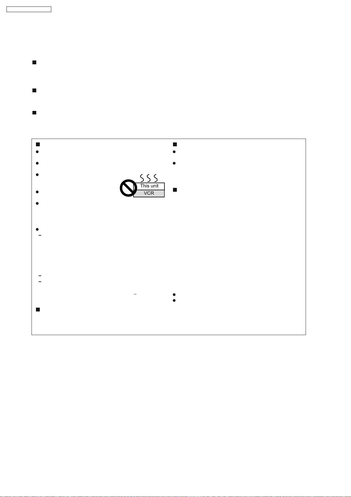
Setup precautions
Do not place in an enclosed area where the rear
cooling fan is covered up.
Place the unit on a surface that is flat and not subject
to vibrati o n or impact.
Do not place on anything that
generates heat like a video
cassette recorder, etc.
Do not place in an area often
subject to temperature changes.
Place in an area where condensation does not occur.
Condensation is a phenomenon where moisture forms on a
cold surface when there is an extreme change in temperature.
Condensation may cause internal damage to the unit.
Conditions where condensation may occur
When there is an extreme change in temperature (moving
from a very hot location to a very cold location, or vice
versa, or when subjected to an air conditioner or when
cooled air directly impacts the unit.) When the HDD
(warms during operation) is subjected to cold air,
condensation may form on the inside of the HDD and may
cause damage to the HDD heads, etc.
When there is high humidity or a lot of steam in the room.
During the rainy season.
In the above situation, without turning the unit on, let the
unit adjust to the room temperature and wait 2 3 hours until
condensation is gone.
Cigarette smoke, etc. causes malfunction
or breakdown
The unit may breakdown if cigarette smoke or bug spray/
vapor, etc. gets inside the unit.
While operating
Do not move the unit or subject to vibration or impact. (The
HDD may become damaged.)
Do not remove the AC mains lead from the household AC
mains socket, or flip the power breaker switch.
While the unit is on, the HDD is rotating at high speed. Sound
or movement due to rotation is normal.
When moving the unit
1.
Remove the CD.
2.
Turn the unit off.
3.
After "GOOD-BYE" is finished displaying, remove the
plug from the wall within 2 minutes, or wait until
conversion and analysis is complete to remove the AC
mains lead from the household mains socket.
4.
Once the HDD is no longer rotating and has come to a
complete stop (after waiting about 2 minutes), move
the unit carefully so as to avoid any vibration or shock.
(After the power has been turned off, the HDD will
briefly continue to rotate due to inertia.)
After the power to the unit has been turned off, (unit enters
"Standby Mode"), if there are recorded tracks that have not
yet been converted or analyzed, the HDD will begin
conversion and analysis of these recorded tracks after about
2 minutes.
During conversion/analysis:
Do not remove the AC mains lead.
If you are using an extension cord and/or power strip with a
power switch, do not switch the power to off.
14
Page 15

7 Accessories
Remote control
FM antenna
SA-PTX7EB / SA-PTX7EG
Speaker cable (4M)
Speaker cord (4M/White)
AC cord
AC cord
(For EB)
Speaker cord (4M/Red)
Din adaptor
(For EB)
15
Page 16
ENTER
SA-PTX7EB / SA-PTX7EG
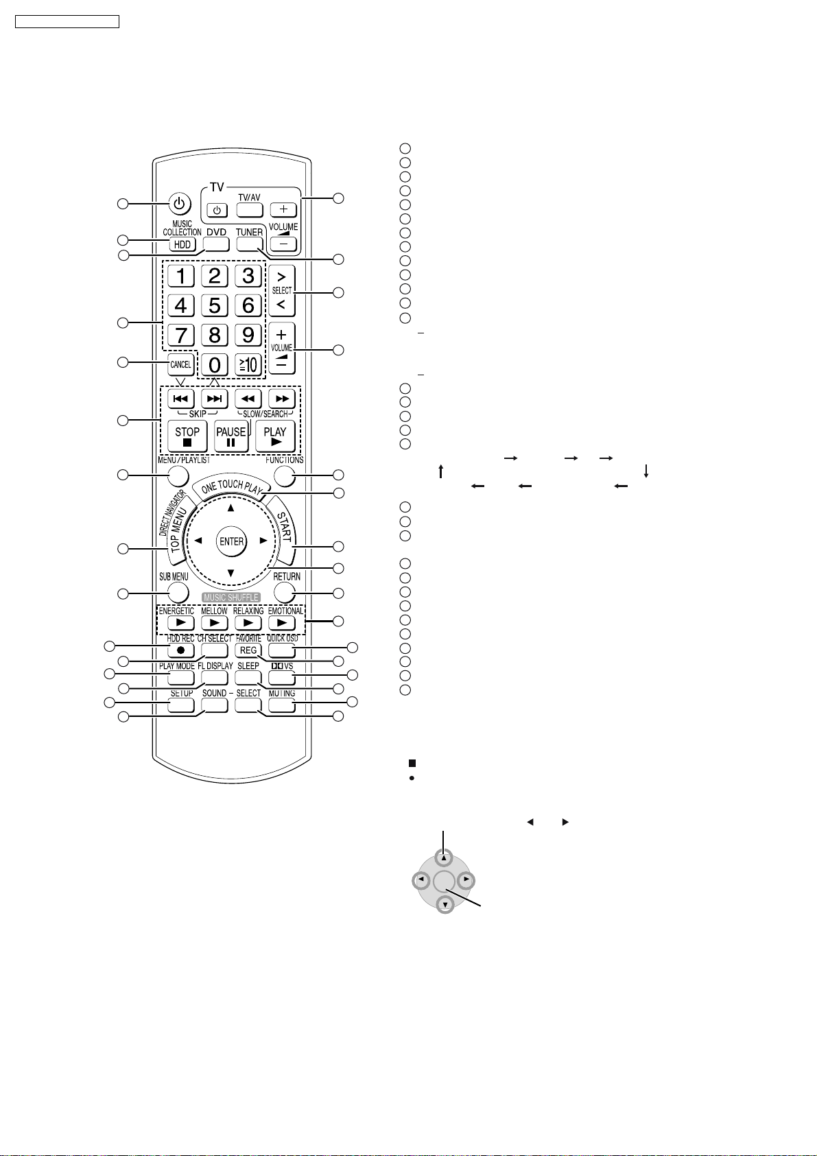
8 Operation Procedures
8.1. Remote Control Key Buttons Operations
1
2
3
1
2
3
4
5
6
7
16
17
18
19
20
21
8
9
10
11
12
13
14
15
22
23
24
25
26
27
28
29
30
31
4
5
6
7
8
9
10
11
12
13
14
15
16
17
18
19
20
21
22
23
24
25
26
27
28
29
30
31
Turn the unit on (OI page 16)
Select the HDD drive (OI page 31)
Select the DVD/CD drive
Select channels and title numbers, etc./Enter numbers
Cancel items
36, 37
Basic operations for playback (OI page 31,
Show a disc menu or playlist (OI page 38,
Show a disc top menu or program list (OI page 37,
)
40, 48)
38
Show sub menu
Start recording to HDD (OI page 29)
Select speaker channels (OI page 76)
53
Select play mode (OI page 50,
)
Switch information on the main unit’s display
When the selector is set to "DVD/CD", "USB",
time, track
depending on
number information, etc. can be switched
what is being played.
elapsed
When listening the RDS broadcasting (OI page 59)
85
Show Setup menu (OI page 16,
)
Select the sound effect to set (OI page 76)
Television operations
Select the FM tuner
Select the source
FM
Music Collection DVD/CD
OPTION MUSIC PORT AUX
USB
TV Audio
Adjust the volume
Show FUNCTIONS window
Start up and play a disc automatically/control both the
home theater system and the television (OI page 70)
Show Start menu (OI page 24)
Selection/enter, frame-by-frame (OI page 37)
Return to previous screen
Music shuffle (OI page 35)
Show Quick OSD (OI page 55)
Register the current track to Favorites (OI page 63)
Turn Dolby Virtual Speaker on/off (OI page 77)
Set SLEEP timer (OI page 80)
Mute the sound (OI page 80)
Set the sound effect (OI page 76)
)
Using the cursor
Select items on menu screens and set items.
Press up, down, left, or right to select an item.
You can also move frame-by-frame (backward/forward).
While paused, press [ ] or [ ] (left/right).
ENTER
Press [ENTER] to confirm.
16
Page 17
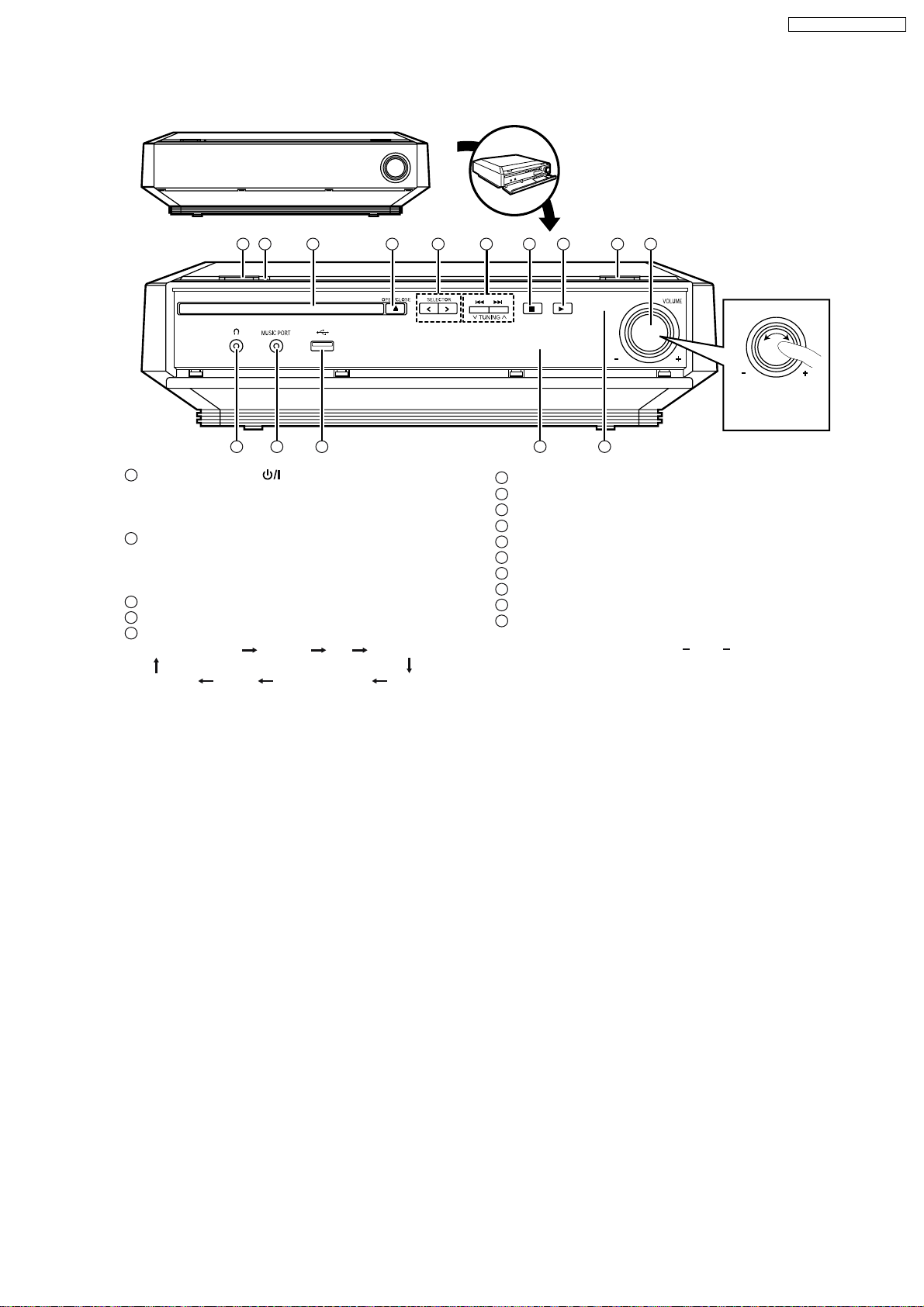
8.2. Main Unit Key Buttons Operations
1 2 3 4 5 6 7 8 9 10
SA-PTX7EB / SA-PTX7EG
When opening and closing the front
cover, be careful not to touch the power
button, especially during recording.
VOLUME
Adjust the volume
of the main unit.
11 12
1
Standby/on switch (
13
) (OIpage16)
Press to switch the unit from on to standby mode or vice versa. In
standby mode, the unit is still consuming a small amount of
power.
2
Standby/on indicator
When the unit is connected to the AC mains supply, this indicator
lights up in standby mode and goes out when the unit is turned
on.
3
Disc tray
4
Open/close disc tray (OI page 11)
5
Select the source
Music Collection DVD/CD FM
OPTION MUSIC PORT AUX
USB
TV Audio
14 15
6
Skip, Select preset radio stations/channels
7
Stop playback (OI page 31
8
Start playback (OI page 31
9
Start recording to HDD (OI page 29)
10
Adjust the volume
11
Connector for headphones (OI page 80)
12
Connector for external device (OIpage 80)
13
USB terminal (OI page 23)
14
Display (OI page 11)
15
Remote control signal sensor
Rear panel terminals (OI page 14
, 36,
, 36,
37)
37)
15, 91 94
)
17
Page 18
SA-PTX7EB / SA-PTX7EG
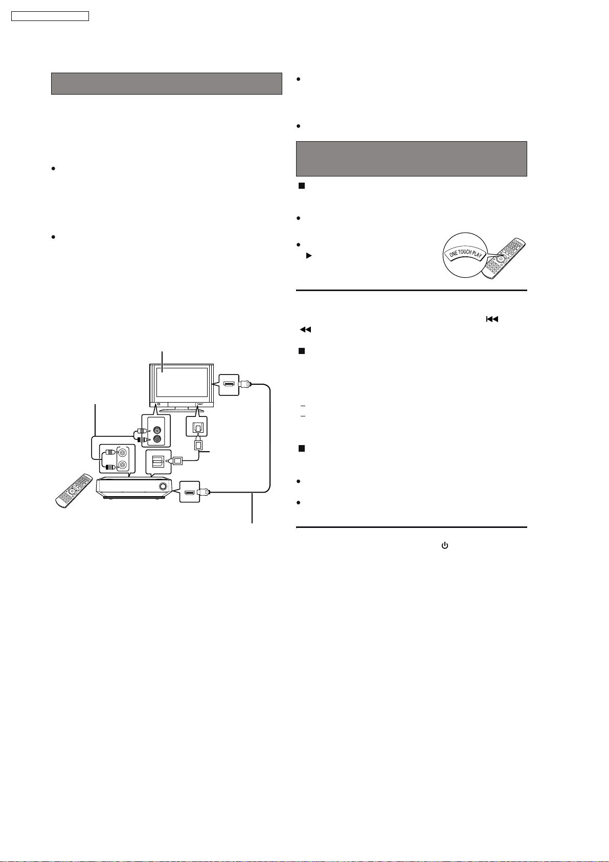
8.3. Using the EZ Sync HDAVI Control
VIERA Link "HDAVI Control"
VIERA Link "HDAVI Control" is a convenient function that offers
linked operation of this unit, and a Panasonic TV (VIERA)
under "HDAVI Control".
You can use this function by connecting the equipment with the
HDMI cable. See the operating instructions for connected
equipment for operational details.
VIERA Link "HDAVI Control", based on the control functions
provided by HDMI which is an industry standard known as
HDMI CEC (Consumer Electronics Control), is a unique
function that we have developed and added. As such, its
operation with other manufacturers’ equipment that supports
HDMI CEC cannot be guaranteed.
This unit supports "HDAVI Control 2" function. The TV with
"HDAVI Control 2" function enables the following operation:
VIERA Link Control only with TVs remote control (for "HDAVI
Control 2") (OI page 71).
"HDAVI Control 2" is the newest standard (current as of
February, 2007) for Panasonic s HDAVI Control compatible
equipment. This standard is compatible with Panasonic’s
conventional HDAVI equipment.
VIERA Link "HDAVI Control"
compatible television
HDMI IN
Audio cable
(not included)
TV IN
AUDIO
OUT
TV IN
L
R
AUDIO
OUT
L
R
OPTICAL IN (TV)
Main unit
Connect this when you want to output TV audio from this
*
unit’s speakers as digital audio.
OPTICAL
OUT
Optical digital
audio cable
(not included)
HDMI AV OUT
HDMI cable
(not included)
*
*
It is recommended that you use Panasonic s HDMI cable.
Recommended part number:
RP-CDHG15 (1.5 m), RP-CDHG30 (3.0 m),
RP-CDHG50 (5.0 m), etc.
Non-HDMI-compliant cables cannot be utilized.
Functions made possible with VIERA Link
"HDAVI Control" are...
One-touch theater playback
You can turn on this unit and television, and start playing the
disc with a single press of a button.
This operation is for "DVD/CD" only.
Press [ONE TOUCH PLAY].
This function also works if you press
[ ] (PLAY) on this unit’s remote
control when this unit is in standby
mode.
[Note]
Playback may not be immediately displayed on the television. If
you miss the beginning portion of playback, press [ ] or
[ ] to go back to where playback started.
Power on link
The television automatically turns on and the corresponding
display appears when the following operations are performed
with the television in standby mode. Audio output is also
automatically switched to this unit’s speakers.
When you start playback on this unit.
When using the GUI (display screen) to perform an action.
[e.g., Start menu screen (IO page 24)]
Power off link
When the television is turned off, this unit goes into standby
mode automatically.
This function works only when "Music Collection", "DVD/CD"
or "TV Audio" is selected as the source on this unit.
When the television is turned on, this unit does not turn on
automatically.
[Note]
Only this unit turns off when you press [ ] for shutting it down.
Other connected equipment compatible with VIERA Link
"HDAVI Control" stays on.
Preparation
1 Confirm that the HDMI connection (OI page 91) has been
made.
2 Set "VIERA Link" to "On" (OI page 87, HDMI menu).
3 To complete and activate the connection correctly, turn on
all VIERA Link "HDAVI Control" compatible equipment and
set the television to the corresponding HDMI input mode for
this unit.
Whenever the connection or settings are changed, reconfirm
the points above.
18
Page 19
SA-PTX7EB / SA-PTX7EG
Auto input switching
When you switch the television input to TV tuner mode, this
unit will automatically switch to "TV Audio ".
If you want to output digital audio, connect the optical cable
*
(OI page 70) and select "DIGITAL IN" in "TV Audio Input"
menu (OI page 88).
When you start playback on this unit, the television will
automatically switch to the HDMI input mode for this unit.
Also from the Start menu, the input mode will be switched.
*
Speaker control
You can select whether audio is output from this unit or the
television speakers by using the television menu settings. For
details, refer to the operating instructions of your television.
Home theater
Theater speakers are active.
When this unit is in standby mode, changing the television
speakers to theater speakers in the television menu will
automatically turn this unit on and select TV Audio as the
source.
If you want to output digital audio, connect the optical cable
*
(OI page 70) and select "DIGITAL IN" in "TV Audio Input"
menu (OI page 88).
The television speakers are automatically muted.
You can control the volume setting using the volume or mute
button on the TV s remote control. (The volume level is
displayed on this unit’s FL display.)
To cancel muting, you can also use this unit’s remote control
(OI page 90).
If you turn off this unit, television speakers will be
automatically activated.
*
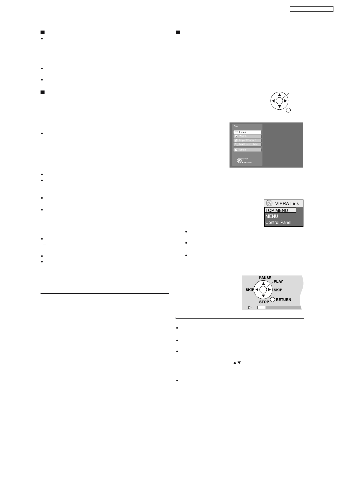
VIERA Link Control only with TV’s remote
control (for "HDAVI Control 2")
You can control the disc menus of this unit with the TV’s remote
control when using the "Music Collection", "DVD/CD", "FM",
and "USB" source. When operating the TV’s remote
control, refer to the illustration below for operation buttons.
1 Select the operation menu by using the television menu
settings. (For details, refer to the operating instructions of
your television.)
2 Select the desired item on the Start menu (OI page 24).
If you select "Disc" in "Listen" or "Watch" on the Start
menu
"VIERA Link" menu is displayed. Select the desired item.
ENTER/
PLAY
RETURN
TV
Television speakers are active.
The volume of this unit is set to "0".
This function works only when "DVD/CD" or "TV Audio" is
selected as the source on this unit.
Audio output is 2-channel audio.
Audio from the CD is not output from the television speakers
while recording to the HDD. However, if "Listening while
Recording" is selected, audio will be output from this unit’s
speakers. In this case, operate the volume settings with this
unit s remote control.
[Note]
Depending on the type of TV, the TV settings, or operations
performed on the TV, Speaker Control may be automatically
set to "Home theater".
"TOP MENU": Shows a disc top menu (OI page 37)
or program list (OI page 38).
"MENU": Shows a disc menu (OI page 36) or
playlist (OIpage 38).
"Control Panel": The basic operations for playback
discs are available.
e.g., "DVD/CD"
[Note]
Depending on the menu, some button operations cannot be
performed from the TV’s remote control.
"Control Panel" can be selected directly by using a button on
the TV’s remote control (e.g. [SUB MENU]).
Depending on the situation, not only the VIERA Link menu, but
this unit’s Start menu may be displayed as well. At this point,
select "Disc" by pressing [ ] (TV’s remote control) and
selecting "Listen" or "Watch". After that, you can operate the
VIERA Link menu by operating the TV remote control.
You cannot input numbers with the numbered buttons on the
remote control ([0] to [10]). Use this unit’s remote control to
input the IP Address, etc.
19
Page 20

SA-PTX7EB / SA-PTX7EG
8.4. Using the Music Port
The Music Port allows you to connect and enjoy music from an
external device (e.g. MP3 player) through this unit.
Preparation
To avoid distorted sound, make sure that any equalizer
function of your external device is turned off.
1
2
Reduce the volume and connect the external device
(not included).
Plug type: 3.5 mm stereo mini plug
VOLUME
External device
Reduce the volume before connecting.
Press [ SELECT ] to switch the selector to "MUSIC
PORT".
3
Adjust the external device volume to a normal
listening level, and then adjust the volume of the main
unit with [ VOLUME].
20
Page 21
8.5. Using the iPod
SA-PTX7EB / SA-PTX7EG
By inserting SH-PD10 (not included) into the OPTION port
and connecting iPod, you can play tracks (audio) through this
unit s speakers. Additionally, you can use the remote control for
this unit to perform operations such as play, stop, and record
operations on iPod.
Only audio tracks can be recorded from iPod.
*
Preparation
1 Connect the SH-PD10 and iPod as shown on
2 Press [ SELECT ] to switch the selector to "OPTION".
OI page 72.
Playing tracks of iPod with the remote
control for this unit
By performing the following operations on the remote control,
you can play tracks from iPod.
PLAY
,
VOLUME] Volume adjust
[
Play will continue from the last track you were listening to
before connecting SH-PD10 and iPod.
PAU S E
SKIP
SEARCH
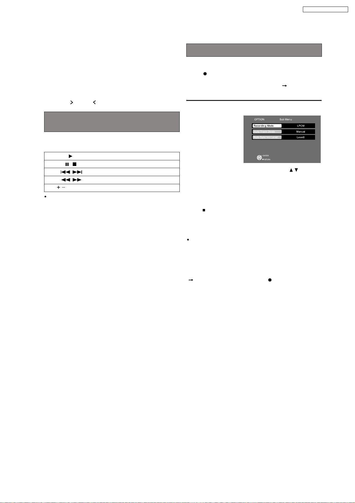
Recording tracks from iPod to the HDD
You can record tracks from iPod to the HDD.
*
Press [ HDD REC].
Recording starts in the set recording mode ( below) and
playing of iPod also starts automatically.
To change the recording mode
1 Press [SUB MENU] while stopped.
2 Select "Recording Mode" (OI page 27) with [ ] and
make changes.
In addition to the recording mode, you can also change
"Auto Track Divide" (OI page 42), or "Auto Synchro Level"
(OI page 42).
To stop partway through
Press [ ].
To return to the previous screen
Press [RETURN].
[Note]
If "No compatible equipment is connected" is displayed, then
no OPTION-compatible equipment is connected to the
OPTION port.
[Tips]
To select a track you want to record
In "Playing tracks of iPod with the remote control for this unit"
( left), operate the iPod, and press [ HDD REC] after
pausing at the beginning of the track you want to record.
21
Page 22
SA-PTX7EB / SA-PTX7EG
8.6. Disc Information
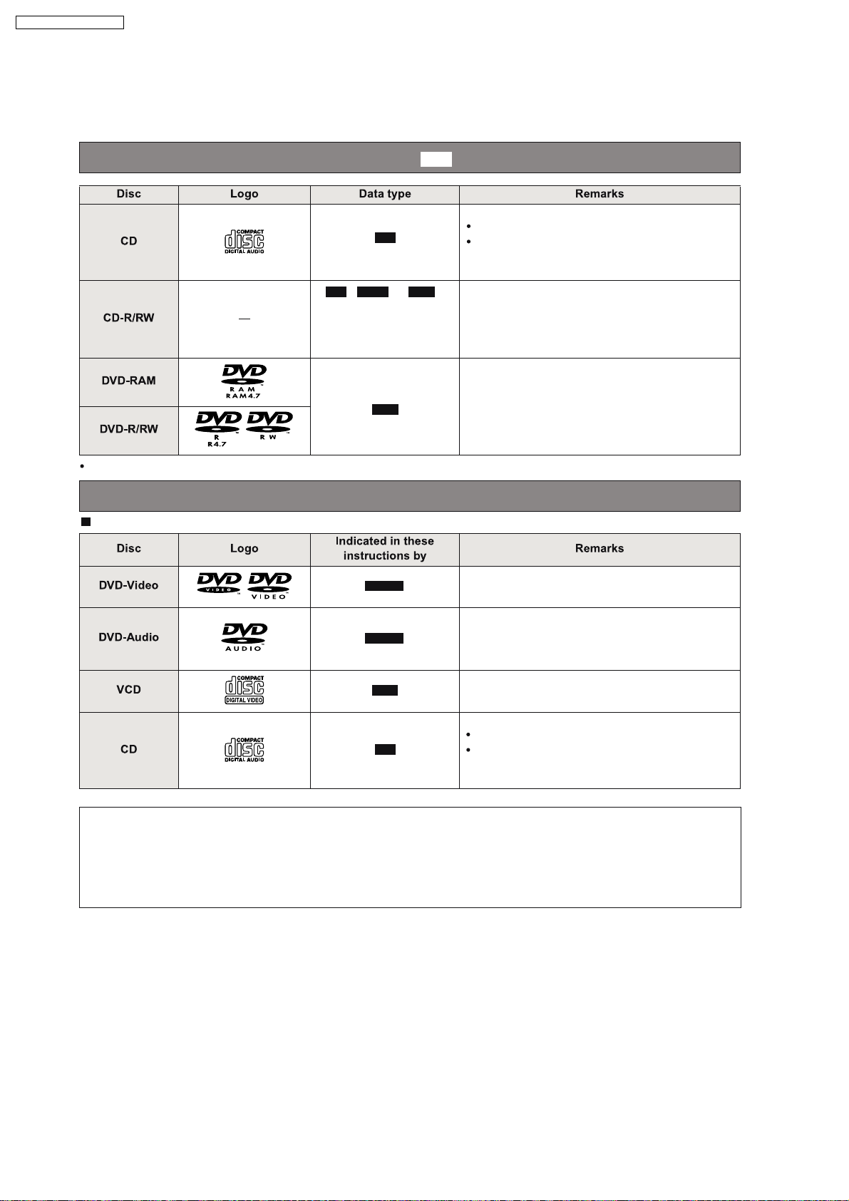
8.6.1. Disc Playability (Media)
Discs that can be recorded to this unit’s HDD ()
CD
WMA MP3
CD
/ /
1
*
See also "File Extension
Type Support (WMA/
MP3/JPEG/MPEG4/DivX)"
(Section 8.6.2.)
MP3
DVD content cannot be recorded to this unit’s HDD (except for MP3 files in recordable DVD).
HDD
Music discs
This unit is not compatible with HDCD.
Operation and sound quality of CDs that do not
conform to CD-DA specifications (copy control
CDs, etc.) cannot be guaranteed.
1
*
1
By recording in CD-DA, WMA, or MP3 format, and
*
closing the session or finalizing the CD-R/CD-RW
disc when recording is complete, you can record
tracks from the disc to this unit s HDD.
2
A process that allows play on other equipment.
*
This unit can record only MP3 files on these
recordable DVDs. DVD-R/RW discs need to be
finalized.
Discs that can be played
Commer ci al di scs
DVD-V
High quality movie and music discs
2
*
Regarding DVD-Audio
DVD-A
VCD
CD
High fidelity music discs
Some DVD-Audio discs contain DVD-Video
*
content. To play DVD-Video content, select "Play
as DVD-Video" (OI page 61, Other Menu).
Music discs with video
Including SVCD (Conforming to IEC62107)
Music discs
This unit is not compatible with HDCD.
Operation and sound quality of CDs that do not
conform to CD-DA specifications (copy control
CDs, etc.) cannot be guaranteed.
*
Some multi-channel DVD-Audio will prevent down-mixing (OI page 108, Glossary) of all or part of their contents if
this is the manufacturer’s intention. When playing such discs, or such parts of the disc, unless the number of
connected speakers is the same as the disc s channel specification, audio will not be output properly (e.g., part of
the audio is missing, multi-channel audio cannot be selected and audio is played in two channels). Refer to the
disc s jacket for more information.
22
Page 23
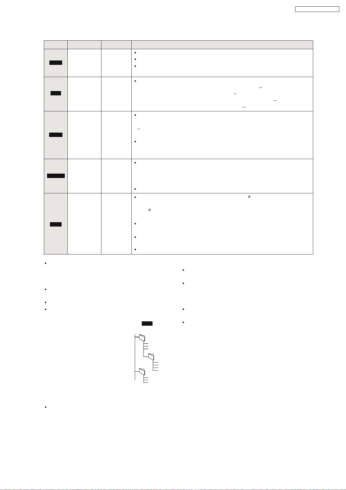
8.6.2. File Extension Type Support (WMA/MP3/JPEG/MPEG4/DivX)
Format Disc Extension Reference
Compatible compression rate: between 48 kbps and 320 kbps
WMA
MP3
JPEG
MPEG4
DivX
CD-R/RW
DVD-RAM
DVD-R/RW
CD-R/RW
DVD-RAM
DVD-R/RW
CD-R/RW
DVD-RAM
DVD-R/RW
CD-R/RW
DVD-RAM
DVD-R/RW
CD-R/RW
".WMA"
".wma"
".MP3"
".mp3"
".JPG"
".jpg"
".JPEG"
".jpeg"
".ASF"
".asf"
".DIVX"
".divx"
".AVI"
".avi"
You cannot play WMA files that are copy protected.
This unit is not compatible with Multiple Bit Rate (MBR: a file that contains
the same content encoded at several different bit rates).
Sampling frequency and compatible compression rate
DVD-RAM, DVD-R/RW :11.02, 12, 22.05, 24 kHz (8 160 kbps)
44.1, 48 kHz (32 320 kbps)
CD-R/RW : 8, 11.02, 12, 16, 22.05, 24 kHz (8 160 kbps)
32, 44.1, 48 kHz (32 320 kbps)
JPEG files taken on a digital camera that conforms to DCF Standard
Version 1.0 are displayed.
Files that have been altered, edited or saved with picture editing
software may not be displayed.
This unit cannot display moving pictures, MOTION JPEG and other such
formats, still pictures other than JPEG (e.g., TIFF) or play pictures with
attached audio.
You can play MPEG4 data [conforming to SD VIDEO specifications (ASF
standard)/MPEG4 (Simple Profile) video system/G.726 audio system]
recorded with the Panasonic SD multi cameras or DVD recorders with this
unit.
The recording date may differ from that of the actual date.
Plays all versions of DivX video (including DivX
6) [DivX video system/
MP3, Dolby Digital or MPEG audio system] with standard playback of
media files.
DivX
Functions added with DivX Ultra are not supported.
DivX files greater than 2GB or have no index may not play properly on this
unit.
This unit supports all resolutions up to maximum of 720 k 480 (NTSC)/
720 x 576 (PAL).
You can select up to 8 types of audio and subtitles on this unit.
SA-PTX7EB / SA-PTX7EG
If groups were created away from the root like "002
group" in the illustration below, the eighth one onwards
is displayed on the same vertical line in the menu
screen.
There may be differences in the display order on the
menu screen and PC screen.
This unit cannot play files recorded using packet write.
This unit is not compatible with ID3 tags.
Naming folders and files (Files
are treated as contents and
folders are treated as groups on
this unit.)
At the time of recording, prefix
folder and file names. This should
be with numbers that have an
equal number of digits, and should
be done in the order you want to
play them (this may not work at
e.g.,
root
MP3
001 group
001
003 group
001 track.mp3
002 track.mp3
003 track.mp3
002 group
001 track.mp3
002 track.mp3
003 track.mp3
004 track.mp3
001 track.mp3
002 track.mp3
003 track.mp3
times).
DVD-RAM
Discs must conform to UDF 2.0.
DVD-R/RW
Discs must conform to UDF bridge (UDF 1.02/
ISO9660).
This unit is not compatible with multi-session. The
default session only is played.
CD-R/RW
Discs must conform to ISO9660 level 1 or 2 (except for
extended formats).
This unit is compatible with multi-session but if there
are a lot of sessions it takes more time for play to start.
Keep the number of sessions to a minimum to avoid
this.
23
Page 24
SA-PTX7EB / SA-PTX7EG
9 New Features
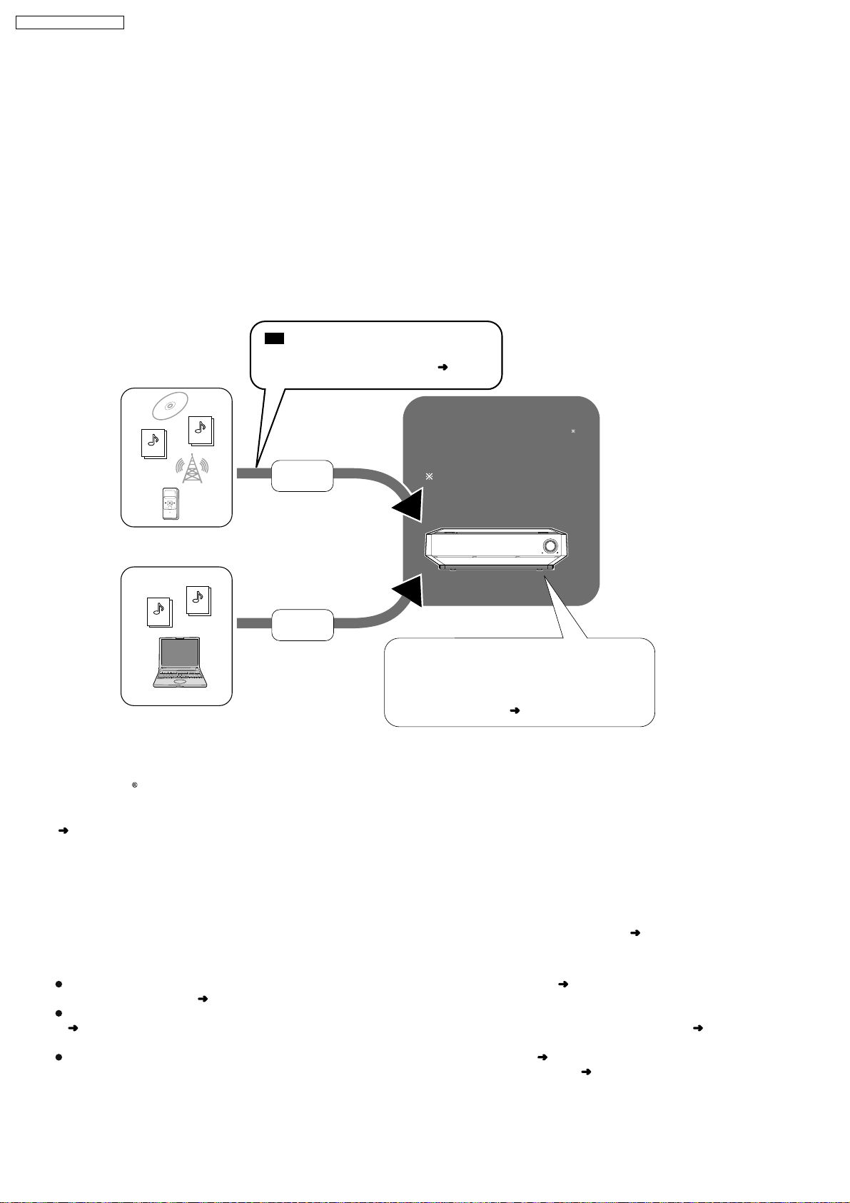
9.1. As a Music Jukebox (Using HDD)
Recording
This unit can record audio to the internal HDD from a variety of sources including commerical CDs, radio, music files (WMA/
MP3), and audio from externally connected devices (portable digital audio players, etc.). This unit can also access the Gracenote
database to obtain title information for music CDs, radio broadcasts, or other analog recordings made with externally connected
devices. (For recording details, see page 26 of operating instruction.)
Importing from a PC
You can import WMA/MP3 files from your PC to this unit. This differs from recording because the files are saved in the HDD in the
same format as they are saved on your PC. (LPCM and AAC conversion is not performed.)
Automatically connects to the
CD
Gracenote database and track title
Various audio sources
MP3
WMA
WMA/MP3 file on PC
information, etc. is obtained (
RECORD
All tracks recorded
are saved as LPCM.
below).
Music Jukebox
You can record up to 39,000
songs in the Music Jukebox.
The number of songs depends
upon various conditions.
VOLUMEVOLUME
This unit
MP3
WMA
IMPORT
Imported WMA/MP3
files are saved "as-is"
(without conversion) in
this unit’s HDD.
After tracks recorded from sources other than
a CD or WMA/MP3 files imported from a PC
are saved in this unit’s HDD, you can manually
access the Gracenote database to obtain track
title information, etc. (
below)
9.1.1. Built-in Gracenote® Database
The Gracenote
By connecting to the Internet, the unit can access the Gracenote server and obtain the most recent CD title information. When a
CD is inserted or recording from a CD begins, the unit will automatically search for and obtain information about the inserted CD
page 28 of operating instruction).
(
If this unit is not connected to the Internet:
A portion of the Gracenote database comes pre-installed on this unit, so titles and artist information can be obtained. Please note
however that the newest CD titles, etc. may not be registered yet to the internal database. This unit has an internal database
containing information for approximately 350,000 album titles.
Searching for titles other than on CD:
Using the Gracenote database, information can also be obtained for other types of tracks recorded to the HDD (
of operating instruction,
them automatically).
If it takes a long time to access the Gracenote database, check if the unit s network connection ( page 94 of operating instruction)
and the network settings (
Some CDs may have title information that is similar to other CDs. In this case, try obtaining the CD title information again
(
page 67 of operating instruction), or after recording to the HDD has completed enter the CD title information manually ( page 66
of operating instruction).
For some CDs, multiple title suggestions will be found, therefore select the appropriate title ( page 67 of operating instruction).
When you want to change the title, manually make changes after recording to the HDD is complete (
database is a database used to search and retrieve CD title information.
page 67
Searching for track names, artist names and album names within the Gracenote database and entering
page 96 of operating instruction) are correct.
page 66 of operating instruction).
24
Page 25

9.1.2. Types of Recordings
You can make these kinds of recordings.
Recording tracks from a
music CD (CD-DA)
(Commercial CD, Recordable CD)
Recording WMA/MP3 tracks
from recordable discs
(Recordable CD or DVD) or
USB devices
Digital
recording
Analogue
recording
SA-PTX7EB / SA-PTX7EG
This unit’s HDD
VOLUME
Recording from the FM radio
Recording from an external
device
IMPORTANT
DVD content cannot be recorded to this unit’s HDD (except for MP3 files in recordable DVD).
Analogue
recording
Analogue
recording
How recordings work
Tracks are initially recorded to the HDD and saved as LPCM. When the recording mode is set to AAC, AAC conversion takes
place while the unit is in standby mode. In addition to AAC conversion, track analysis for the "Music Shuffle" function (
of operating instruction) also takes place during standby mode.
While the unit is in standby modeInitially recorded as LPCM Track data in the HDD
Recording in
LPCM
recording
mode
Recording in
AAC
recording
mode
Audio signal is recorded
(uncompressed)
Record
LPCM
This unit’s
HDD
Conver ted to AA C
and co mp ressed
LPCM
AAC
Analysis
for Music
Shuffle
page 35
LPCM
AAC
AAC
LPCM data
is deleted
With LPCM recording mode, AAC data created (XP mode only) is not displayed in the Track List.
About AAC conversion of recorded tracks and Music Shuffle analysis
Conversion/analysis is performed when the unit is in standby mode. 2 minutes after the unit is set to standby mode, conversion/
analysis starts and the unit s display starts to show "_ _ _ _". Leave the power cord plugged in.
You can also perform conversion/analysis immediately (
This unit usually takes about one-third of the recording time to complete analysis and conversion.
For example, a 60-minute recording will take about 20 minutes to complete conversion and analysis. (For tracks imported from
a PC, time will be shorter as the tracks only need to be analyzed.)
Tracks can be played even if conversion and analysis is incomplete. However, the same track may sound slightly different before
and after AAC conversion.
You can also compress LPCM tracks to AAC to increase the amount of the available space on the HDD (see page 47 of
operating instruction).
page 46 of operating instruction).
25
Page 26
SA-PTX7EB / SA-PTX7EG
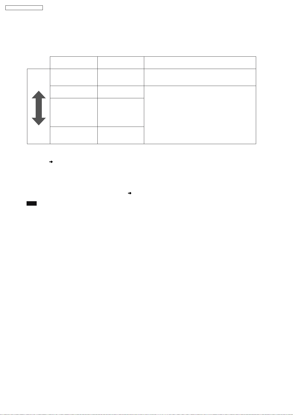
9.1.3. Recording Modes
With these settings you can adjust the audio quality when recording tracks to the HDD. Recordings made with higher bitrates use
more space, reducing the total available space on the HDD.
Recording mode
Recording mode/
bitrate
Higher
audio
quality
LPCM Approx. 104 hours
AAC(XP)
128 kbps
AAC(SP)
96 kbps
Possible recording
time
Approx. 1,230 hours
Approx. 1,640 hours
Explanation
The audio signal is digitally recorded without any
compression.
The audio is initially recorded as LPCM and converted to
AAC when this unit is in standby mode.
AAC is a compression format which compresses the audio
data into a smaller size. Audio quality and the amount of
tracks that can be recorded will differ depending on the
bitrate.
Longer
recording
time
Recording mode settings at the time of purchase:
The recording mode for each selector is set to "LPCM" at the time of purchase. The recording mode for each selector can be set
individually (
If you want to change the recording mode to AAC, please note the following:
Recordings made to this unit are initially recorded in LPCM, and then are converted to AAC. Therefore if you are making
continuous, long recordings, the maximum amount of recordings you can make must fit within the LPCM limits for maximum
possible recording time as described in the chart above. In the event that you are making many recordings, continue recording
after the music data has been converted to AAC format (
Note
LPCM audio quality does not exceed the audio quality of the original recording.
AAC(LP)
64 kbps
OI page 28).
Approx. 2,460 hours
OI page 26, How recordings work).
26
Page 27
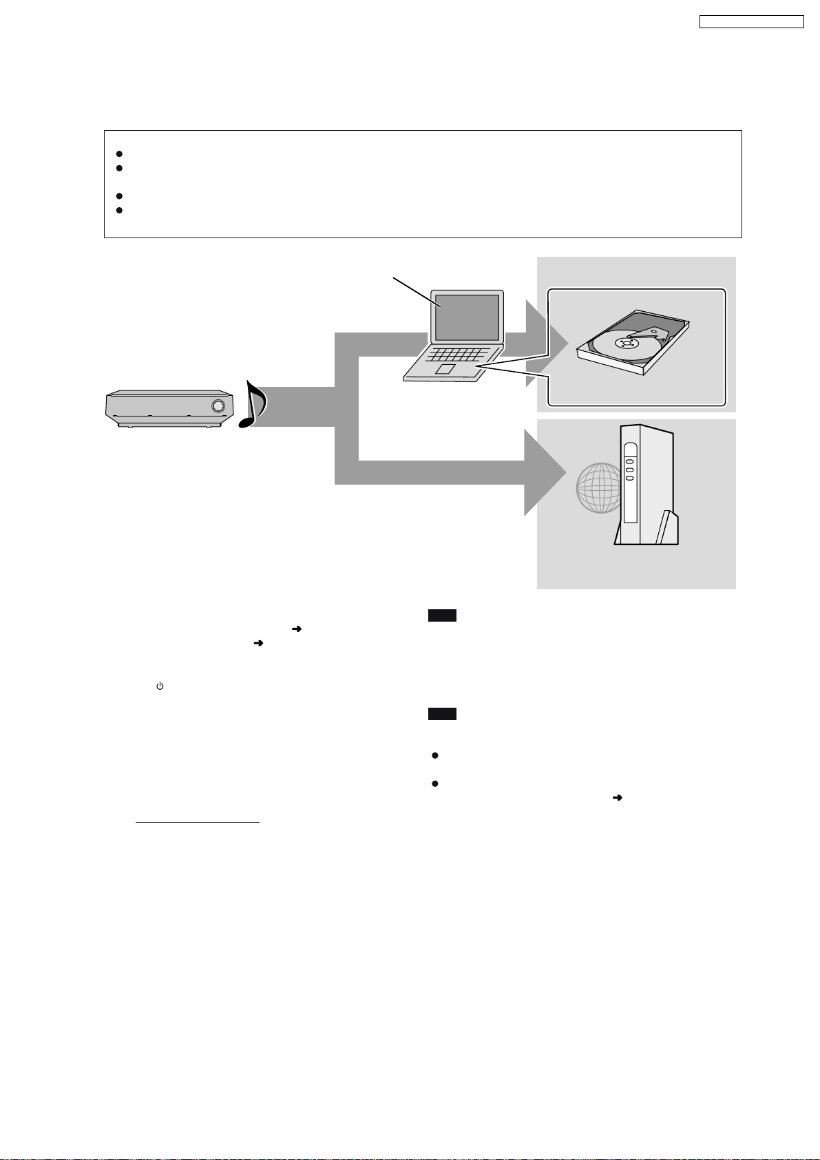
9.1.4. Backing up to HDD Data to a PC
We recommend backing up the tracks on the HDD regularly using a PC or NAS (Network Attached Storage). In the event that this
unit requires service and the music data is damaged or lost, you can restore music from the last time you backed up.
The necessary equipment and recommended operating system for creating a backup:
A PC operating with Windows XP SP2 installed
A hard disk drive (HDD) with adequate available space, or a NAS device. Other media (DVD-R, etc.) cannot be used for
creating a backup of your music library.
When creating a backup, we recommend using a fast network connection such as 100BASE-T LAN.
For further information about backups visit the following homepage.
http://panasonic.jp/support/global/cs/audio
SA-PTX7EB / SA-PTX7EG
PC with Windows XP SP2 installed
HDD
Preparation
1 Connect the unit to a PC network (
directly
2 To display the picture turn on the television and select the
3Press[].
4 Press [MUSIC COLLECTION] to switch the selector to
Settings to check on the PC
1
connect it to a PC (
appropriate video input to suit the connections to this unit.
"Music Collection".
Create a folder using the name below, and set the
folder to "Shared". (This folder then becomes the
save destination for the backup data.)
Folder name:
ptxbckup
Music data
OI page 94), or
OI page 84).
Backup destination
PC
HDD(PC)
Internal PC HDD
NAS
Network Attached Storage
Note
About backup data
The backup data is created with encryption. Therefore, backup
data cannot be played or copied to another device.
Furthermore backups can only be restored on the unit from
which it was created.
Tips
If you do not have the equipment required for creating a
backup
Make certain to keep the recording source (CD, files, etc.).
For information about the shared folder settings, see
"Importing WMA/MP3 from a PC" (
OI page 44).
2
Check the PC name.
27
Page 28
SA-PTX7EB / SA-PTX7EG
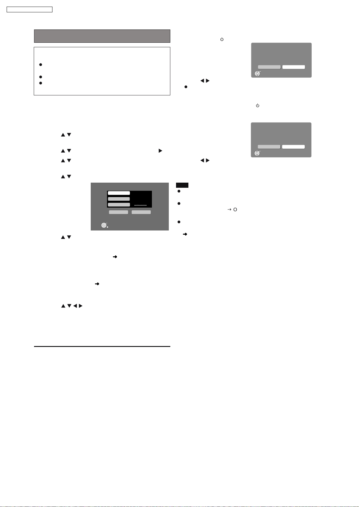
Backing up data recorded to the HDD
Cautions about backup data:
Be careful not to perform any of the following:
Do not open backup data with applications or software,
and do not change the contents.
Do not compress the backup data.
Do not change the backup data file name or change the
saved location.
Perform "Preparation" and "Settings to check on the PC" as
described on OI page 81.
1
Press [SETUP].
2
Press
[ ]
to s
elect "Other Setup" and press
[ENTER].
3
Press
[ ]
to s
elect "Maintenance" and press [ ].
4
Press
[ ]
to s
elect "Backup/Restore" and press
[ENTER].
5
Press
[ ]
to s
elect "Backup" and press [ENTER].
Backup
PC Name
User Name
Pass word
Backup Cancel
ENTER
Cancel
6
Press
[ ]
to s
elect "PC Name" and press [ENTER].
When the PC name is displayed
The PC name and other information that was used when
previous backups and imports (
performed may be displayed. In this case, check the PC
name again, and if necessary, follow the steps below to
make changes.
7
Enter the characters ( OI page 62).
Input the "User Name" and "Password" in steps 6 and 7 in
the same manner.
8
Press [
]
to s
elect "Backup" and press
[ENTER].
Backup begins.
A message will be displayed, indicating that backup is
complete. The unit will briefly stay this way, and then it will
turn off automatically shortly after.
OI page 44) were
To cancel backup
1 Press and hold [ ] during backup.
Backup
This function will pause and the po wer will turn off
immediatel y.
Do you want to contin u e?
No
2Press [
Yes
ENTER
] to select "Yes" and press [ENTER].
This unit turns off and backup canceled.
To continue a previously canceled backup
1 After backup is canceled, press [ ] to turn the unit on
again.
The following message is displayed.
Incomplete Bac kup
Backup is incomplete .
Do you want to resume Bac kup?
No
2Press [
Yes
ENTER
] and select "Yes", then press [ENTER].
Follow the steps given on screen, and start backup again.
Note
When the backup is canceled partway through, the data
becomes unusable. Finish the backup as soon as possible.
The settings for the Power Off Mode for this unit will enter
"Power-Save Mode" (gOI page 88) until the backup is
complete.
When performing a backup, all timer settings will be set to
"Off". If you use a timer, you will need to set to "On" again
OI page 79).
(
If the backup aborted due to critical errors or abnormal
termination
After the message is displayed on the unit, this unit will
automatically turn off.
In this situation, turn the power on again and continue the
backup.
A note about the second (and subsequent) backups
Only newly added tracks and changes made since the
previous backup was created will be backed up, therefore the
backup will take less time to finish than the first time.
To return to the previous screen
Press [RETURN].
28
Page 29
SA-PTX7EB / SA-PTX7EG
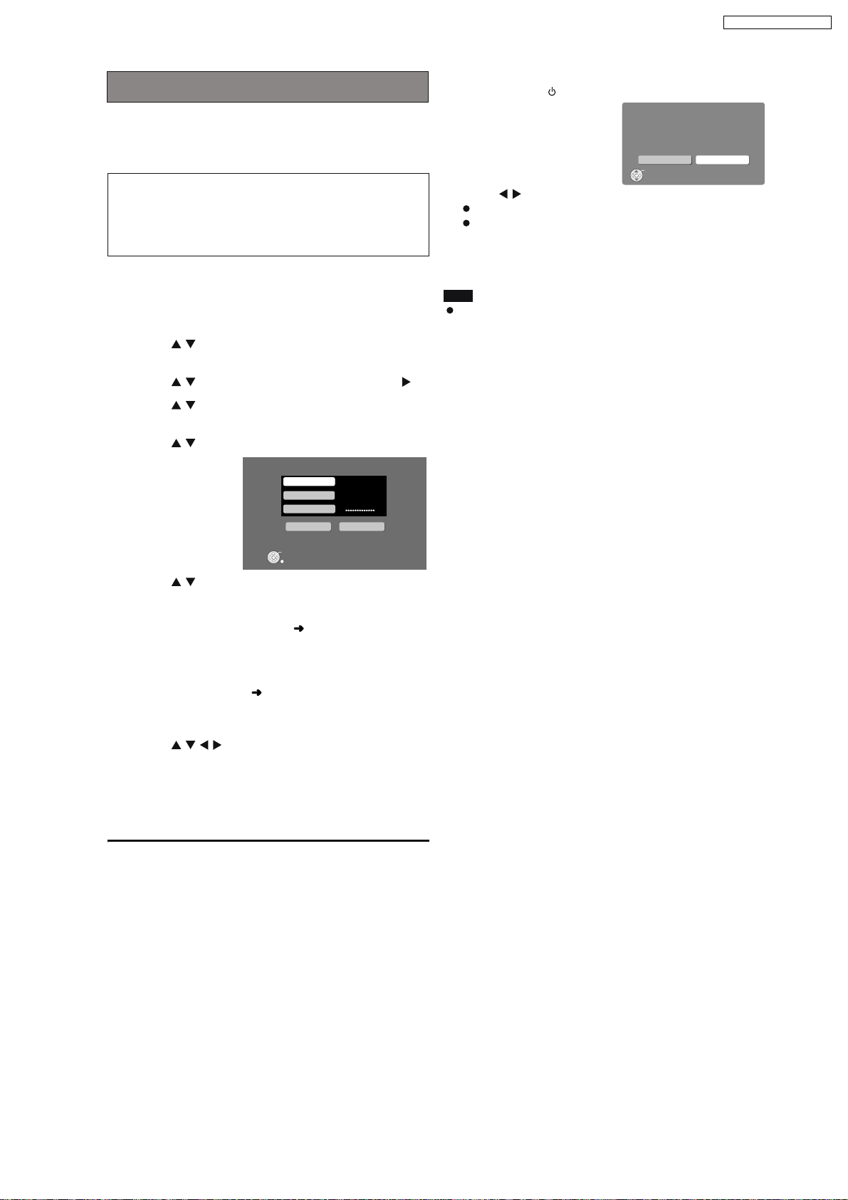
Restoring backed up data
This function will restore the backup data that was saved on
your PC to this unit.
If the HDD requires service, please wait until the HDD has
been repaired before restoring the backup to the HDD.
Restoring the backup data to the HDD will reset the
HDD (no tracks on the HDD). If restoring fails, the
content of the HDD will be lost. When restoring the
backup data, therefore, please exercise the utmost
caution.
Perform "Preparation" and "Settings to check on the PC" as
described on OI page 81.
1
Press [SETUP].
2
Press
[ ]
to s
elect "Other Setup" and press
[ENTER].
3
Press
[ ]
to s
elect "Maintenance" and press [ ].
4
Press
[ ]
to s
elect "Backup/Restore" and press
[ENTER].
5
Press
[ ]
to s
elect "Restore" and press [ENTER].
Restore
PC Name
User Name
Pass word
Restore Cancel
To cancel restore
1 Press and hold [ ] during restoring.
Restore
This function will pause and the po wer will
turn off immediatel y.
Do you want to contin ue?
No
2Press [
Yes
ENTER
] to select "Yes" and press [ENTER].
This unit is turned off and the restore is canceled.
If restore is canceled before completion, all progress up to
the point of cancelation will not be recorded and the HDD
will be completely empty. Restore this unit again later.
Note
Restore may be canceled if your PC is turned off in an
irregular manner or is forced to shut down due to errors. In
this situation, restore again from the beginning. However,
backups may not restore when the backup data contains
abnormalities.
ENTER
Cancel
6
Press
[ ]
to s
elect "PC Name" and press [ENTER].
When the PC name is displayed
The PC name and other information that was used when
previous backups and imports (
OI page 44) were
performed may be displayed. In this case, check the PC
name again, and if necessary, follow the steps below to
make changes.
7
Enter the characters ( OI page 62).
Input the "User Name" and "Password" in steps 6 and 7 in
the same manner.
8
Press [
]
to s
elect Res tore and press
[ENTER].
Restore begins.
A message will be displayed, indicating that restore is
complete. The unit will briefly stay this way, and then it will
turn off automatically shortly after.
To return to the previous screen
Press [RETURN].
29
Page 30
SA-PTX7EB / SA-PTX7EG
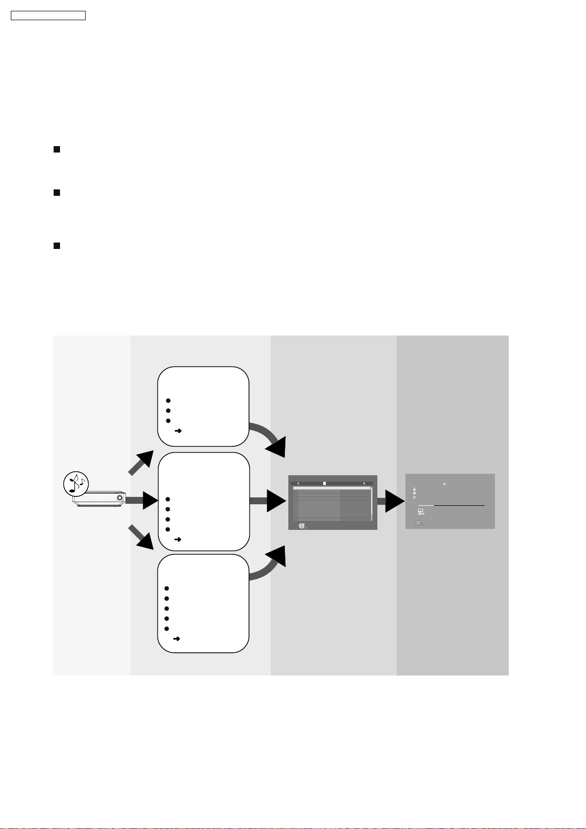
9.2. Easy Location of HDD Recording Contents
You can easily search for tracks that have been recorded to this unit’s HDD by using variety of categories based on your
preferences. From the lists created by your search, you can select the tracks that you want to listen to. These lists that are created
are preferred to as “Playlists”. Tracks are played when a selection is made in a playlist. Playlists are classified into the following
categories.
9.2.1. Playlist Search Method
Playlists with tracks sorted by basic details (artist, album, track)
These playlists are created using basic details such as artist names or album names. Also you can search tracks by track names
(Refer OI page 33).
Playlists generated by Music Shuffle function
"Music Shuffle" is a function that automatically decides the feeling or impression of tracks, and then classifies the track into one of
four different groups. If you select a specific group from "Music Shuffle", the tracks within the group will appear in a random playlist
each time. Depending on the track, some tracks cannot be classified into any
the
User-specific playlists ("Other Playlists" in
top m
Aside from the playlists created by using basic details (as mentioned above), this unit has some other special types of playlists
such as "User Playlists", which allow you to arrange any tracks in any order, or "Most Often Played" playlist, the tracks of which
are automatically selected and arranged based on the frequency of playback. There are other user-specific or automatically
arranged playlists like "Favorites", "Recently Ripped" and "Analog Recorded". For more information about these useful playlists,
(Refer OI page 34).
of Music Shuffle playlists (Refer OI page 35).
groups
e
nu of M
u
s
ic C
o
ll
e
c
tion)
Tracks recorded
to HDD
HDD
Select the playlist Tracks are shown and
select the track
Track is played and
enjoy listening
Select a category to
search for tracks
Artist name
Album name
Track name
OI page 33)
(
Select a playlist from
Music Shuffle
function
VOLUME
Energetic
Mellow
Relaxing
Emotional
OI page 35)
(
Track List (playlist) Main Screen
Music Collection
Eine Kleine Nac ht Musik
Fantasia K.397
Le nozze di Fi garo, over ture
Symphon y No.34
Symphon y No.35 "Haffner"
Symphon y No.40
The Elopement fr om the Harem
Turkischer Mar sch
Six German Dances
Symphon y No.36
Play
RETURN
PL
Playlist001
MOZART
MOZART
MOZART
MOZART
MOZART
MOZART
MOZART
MOZART
MOZART
MOZART
1 of 10
Music Collection > Other Play lists
Mozart
Life with Mozar t
Eine Kleine Nac ht Musik
2:45
LPCM
PL
Repeat
REC
Trac k L is t
Favorites
Tracks 3 of 12
Total Time 56:00
5:42
User-specific playlist
selection
User Playlists
Favorites
Most Often Played
Recently Ripped
Analog Recorded
OI page 34)
(
30
Page 31

You can use several methods to easily find tracks in the HDD that you want to listen to.
Searching for/selecting tracks in the HDD
SA-PTX7EB / SA-PTX7EG
1 From the Music
Collection top menu...
Artists
Albums
Tracks
Music Shuffle
Other Playlists
Random Shuffle
2 Select the desired playlist.
Energetic
Mellow
Relaxing
Emotional
User Playlists
Favorites
Most Often Played
Recently Ripped
Analog Recorded
Tracks will be randomly selected and played.
Searching from various playlists
3 Tracks are shown and
select the track.
Track List
(playlist)
Music Collection
Favorites
Bleep Bleep Daniel Bellman
Don Alan I can feel lo ve
John Carne yChristmas
Alex Elmsle yTrue White
SlydiniSummer vacation
SlydiniPlayhouse
Play
RETURN
1 of 5
4 Playback starts.
Main Screen
Music Collection > Other Playlists
Favorites
Mozart
Life with Mozar t
Eine Kleine Nach t Musik
2:45
Tracks 3 of 12
LPCM
Total Time 56:00
PL
Repeat
REC
Track List
5:42
BAND
HDD
SELECT
N
O
CH SELECT
CH SELECT
FL DISPLAY
SOUND
VOLUME
PLAYPA US ESTOP
FUNCTIONS
U
C
O
H
T
P
E
L
A
Y
S
S
T
T
A
A
R
R
T
T
EMOTIONAL
FAVORITE
2
ND
SELECT
REG
VS
SLEEP
MUTINGSETUP
SELECT
CANCEL
CANCEL
STOP
MENU PLAYLIST
R
O
T
A
G
I
V
A
U
N
T
N
C
E
E
R
I
M
D
P
O
T
ENERGETIC RELAXINGMELLOW EMOTIONAL
ENERGETIC RELAXINGMELLOW
HDDREC
PLAYMODE
HDD
Preparation
1 To display the picture turn on the television and select the
appropriate video input to suit the connections to this unit.
2Press [].
1
Press [START].
2
Press [ ] to select "Listen" and press [ENTER].
3
Press [ ] to select "Music Collection" and press
[ENTER].
Music Collection
Artists
Albums
Tracks
Music Shuffle
PL
Other Pla ylists
Random Shuffle
ENTER
Main Screen
Different ways to search for tracks
Artists
Search by artist name (Refer OI page 33)
Albums
Search by album name (Refer OI page 33)
Tra cks
Search by track name (Refer OI page 33)
Music Shuffle
Tracks are automatically selected from the
Music Shuffle collection playlist (Refer OI
page 35).
Other Playlists
Search from various user-specific playlists
PL
(Refer OI page 34)
31
Random Shuffle
Tracks will be randomly selected and played
(Refer OI page 35).
Page 32

SA-PTX7EB / SA-PTX7EG
9.3. Network Connections (LAN)
9.3.1. Network Connections
By connecting to the Internet, you can use the following functions:
You can obtain the most recent CD title information from the online Gracenote database.
[This unit has an abbreviated Gracenote
connected to the Internet. (
OI page 25, About the Gracenote database)].
Importing WMA/MP3 data ( OI page 44), data backup ( OI page 82), etc., are all functions that use the network.
(Functions other than those listed above are not supported by network services.)
When you have a dedicated Internet connection (such as cable, broadband, etc.), after checking with your Internet Service
Provider (ISP) and the service agreement, make connections and settings using indicated equipment.
For further information about network connection visit the following homepage.
http://panasonic.jp/support/global/cs/audio
database in the HDD. CD title information can be obtained even if you are not
Internet
Telecommunications
equipment (modem, etc.)
Main unit
SPEAKERS
CENTER
(8 )
SUB-
WOOFER
(4 )
FRONT
RL
(8 )
Straight LAN cable (not included)
Hub or broadband router
When using a modem with broadband router capabilities,
and if there are no open modem ports, connect a hub. If
the modem does not have broadband router capabilities,
connect a broadband router.
Use a router that supports 10BASE -T/100BASE -TX.
TV IN
VIDEO S-VIDEO
OUTOUT
DIGITAL
(TV)
AV
OPTION
V.1
DC OUT 5V
500mA MAX
Y
COMPONENT
OPTICAL
VIDEO OUT
IN(TV) AV OUT
OUT
AUX
LRL
P
R
R
P
B
(10BASE-T/
100BASE-TX)
FM
ANT
75
LAN
PC
Note
The name for the terminal may differ depending on the device.
Refer to the operating instructions for the connected device.
Inserting any cable other than a LAN cable in the LAN terminal can damage the unit.
32
Page 33

SA-PTX7EB / SA-PTX7EG
Router settings
We recommend setting the DHCP for the router to "ON" (the setting to automatically assign IP addresses).
This is usually set to "ON", therefore changes may be unnecessary.
Depending on the security settings of the router, this unit may not be able to connect to the Internet.
Settings for this unit
When the DHCP server function is set to "ON", you can use the default settings for this unit; no changes to the settings are
necessary.
Depending on the router settings, you may need to make changes to the network settings on this unit (OI page 96, Changing
the network settings).
Note
CD title information cannot be obtained from the online Gracenote
connection.
database if you connect to the Internet using a Proxy
Responsibility disclaimer
Panasonic will not accept responsibility for unintended consequences, malfunctions, hang-ups, or other damage resulting from
connections of unapproved devices or software.
I mplementing router security requires a high level of knowledge of networking. If you are setting security levels, do so at your
own risk. Panasonic accepts no responsibility for problems caused by security settings. Furthermore, Panasonic cannot
address questions relating to the settings and usage of each device.
33
Page 34

SA-PTX7EB / SA-PTX7EG
9.3.2. Importing WMA/MP3 from a PC
WMA MP3
With a network connection (LAN home network), you can save
WMA/MP3 data from your PC in the HDD of this unit.
You can import recordings without any audio distortion or
degradation.
Supported OS: Windows XP SP2
File formats that can be imported
extensions: WMA,MP3
MP3 files in compliance with MP3 standards
MPEG-1 Audio Layer III
MPEG-2 Audio Layer III (LSF)
compatible bitrate: 32 kbps to 192 kbps
files without copyright restrictions
Tracks can also be Imported from NAS (Network Attached
Storage).
Preparation
1 Connect this unit and the PC to the network (
or
connect this unit and the PC directly (
OI page 94),
OI page 84).
2 To display the picture turn on the television and select the
appropriate video input to suit the connections to this unit.
3Press [].
4 Press [MUSIC COLLECTION] to switch the selector to
"Music Collection".
Preparations and items to check on the PC
1 Set the "Shared Folder" (gOI page 45, Setting the "Shared
Folder"), and move the folder containing WMA/MP3 files to
the "Shared Folder", or move the folder containing WMA/
MP3 files to the "Shared Documents" folder.
It is necessary to name the PC and the PC Shared Folder
using only characters that can be used on this unit. If
necessary, make changes to the "Shared Name" and "Full
Computer Name" on the PC.
2 Checking the PC name (Computer name).
e.g., For "Windows XP Home Edition"
From the "Start" menu, select "System" in "Control Panel",
and click on the "Computer Name" tab, and make note of
the name given in the "Full Computer Name" field.
Main unit operations
From the Main Screen (
1
Press [SUB MENU].
2
Press [ ] to select "Import from PC" and press
OI page 24)
[ENTER].
Impor t from PCMusic Collection
PC Name
User Name
Passwo rd
Shared Folder
Impor t Cancel
ENTER
Cancel
3
Press [ ] to select "PC Name" and press [ENTER].
4
Enter the PC name ( OI page 62) and press [ ] (Set).
ADGJ
F40
Enter the name that you checked in step 2 of
"Preparations and items to check on the PC" (
(Up to 15 characters).
If the PC name, etc. is displayed
If you have previously imported data or performed a
backup (
OI page 81), then PC name, etc. may be
displayed. In this case, check the PC name and make any
changes that may be necessary.
5
Repeat steps 3 and 4 and enter other items.
User Name: The user account name used when
Windows XP was registered.
Password : Password set for the user name
Passwords will be displayed as " *************** ".
Shared Folder: Name of the shared folder on the PC.
6
Press [ ] to select "Import" and press [ENTER].
The list inside the shared folder on the PC will be
displayed.
Folder_003
Folder_001 Updatin g
Folder_002
Folder_004
Impor t from PCMusic Collection
Impor t Complete
Not Impor ted Yet
Not Impor ted Yet
left)
ENTER
[LEFT/RIGHT] to c heck/unc hec k
Cancel
7
Select the folder to be imported with [ ] and add a
check mark with [
].
To select all the folders
Press [SUB MENU] and select "Mark All".
To remove the check marks from all the folders, select
"Unmark All".
34
Page 35

SA-PTX7EB / SA-PTX7EG
8
Press [ENTER].
Impor t from PCMusic Collection
1 Folder(s)
1 file(s)
4.58 GB
Do you want to impor t?
Yes
No
ENTER
Cancel
9
Press [ ] to select "Yes" and press [ENTER].
Import starts and the current status and remaining time is
displayed. After importing is finished, the status message
appears.
If import does not start, refer to "Messages" (gOI page 99)
to address to any problems.
To stop importing
Press [
].
Tracks that finished importing up to the point stopped can be
recorded.
To return to the previous screen
Press [RETURN].
Note
When the unit is set to standby mode, this unit performs
analysis of WMA/MP3 tracks imported to the HDD for Music
Shuffle (gOI page 35). AAC conversion is not performed for
the WMA/MP3 tracks imported from a PC.
Tracks that have not been analyzed will appear in the playlist
screen with a " " mark next to them.
The audio may sound broken up in the space between tracks
imported from a PC.
I f a track contains large data such as JPEG, etc., the track
may be muted or not play at all.
When using NAS (Network Attached Storage), input the user
name and password registered with NAS (gOI page 44,
step 5).
Setting the "Shared Folder"
For further information, refer to the Windows operating
instructions or Windows "Help".
e.g., For "Windows XP Home Edition"
1
Right click on the folder that you want to share, and
select "Sharing and Security...".
2
Add check marks to "Share this folder on the
network" and "Allow network users to make
changes to files".
3
Make note of the "Shared Name" field. (Necessary
for later operations.)
4
Click "OK".
Depending on the PC, stability issues may cause problems
such as tracks to fail to import, or imported tracks may be
unusable, etc. Panasonic and/or its retailer s responsibility
are limited to gross negligence or malicious intent by
Panasonic and/or its retailers. Neither Panasonic nor its
retailers will accept any responsibility for direct or indirect
loss or damage to your music data.
Tips
How titles are added
If the music data on the PC uses music information tags, the
artist name, album name, and track titles will be added.
If there is no tag information, the names of the artist, album
and track are added as shown below.
Artist name: "_Unknown Artist"
Album name: The folder s name of the recorded track
Track name: The file name of the track
About WMA/MP3 data imported to this unit:
Operations for tracks imported from a PC will play and edit
(excluding Combine/Divide functions), etc. in the same manner
as tracks recorded to the HDD in this unit.
35
Page 36

TCP/IP 1
TCP/IP 2
IP Address
Auto Settin g
Auto Settin g
Network Settin gs
Connected to netw o rk.
IP Address
Subnet Mask
0. 0. 0. 0
0. 0. 0. 0
Gateway
0. 0. 0. 0
IP Manual Settin g
Primar y DNS Address
Secondar y DNS Ad dress
0. 0. 0. 0
0. 0. 0. 0
DNS Manual Settin g
[MAC Ad dress]
[IP Ad dress]
[Subnet Mask]
[Gateway ]
[Primar y DNS Ad dress]
[Secondar y DNS Ad dress]
00-00-00-00-00-00
---.---.---.---
---.---.---.---
---.---.---.---
---.---.---.---
---.---.---.---
IP Address
SA-PTX7EB / SA-PTX7EG
9.3.3. Changing the Network Settings
These settings are used if you will connect this unit to a
network.
Preparation
1 To display the picture turn on the television and select the
appropriate video input to suit the connections to this unit.
2Press [].
Common procedures
1
Press [SETUP].
2
Press [ ] to select "Other Setup" and press [ENTER].
3
Press [ ] to select "Network" and press [ ].
4
Press [ ] to select "Network Settings" and press
[ENTER].
The network connection status is displayed.
Manually setting the IP address
In most cases, default settings can normally be used without
making any changes.
When connecting this unit to a network and assigning a fixed
IP address, perform the following settings.
After performing steps 1 4 (
5
Press [ ] to select "TCP/IP 1" and press [ENTER].
6
Press [ ] to select "IP Manual Setting" and press
[ENTER].
7
Press [ ] to select the item to be set and press
[ENTER].
above)
Manually setting the DNS server
In most cases, default settings can normally be used without
making any changes.
When setting an assigned DNS server from your ISP, perform
the following settings.
After performing steps 1 4 (
5
Press [ ] to select "TCP/IP 2" and press
6
Press [ ] to select "DNS Manual Setting" and
press
[ENTER]
.
If "TCP/IP 1" is set to "IP Manual Setting", the "DNS Auto
Setting" will not be displayed.
7
Press [ ] to select the item to be set and press
[ENTER]
8
Enter numbers with the numbered buttons and press
.
[ENTER].
Follow the instructions given by your ISP and enter the
numbers.
The numeric input range is between 0 and 255.
Repeat steps 7 8, and enter numbers for other items.
To return to the previous screen
Press [RETURN].
To exit the screen
Press [RETURN] several times.
If you made an input mistake
Move the cursor with [
numbered buttons.
To delete settings and use default settings
Select "DNS Auto Setting" in step 6 and press [ENTER].
left)
[ENTER]
] and make corrections with the
.
8
Enter numbers with the numbered buttons and press
[ENTER].
After checking the specifications for your broadband
router, enter each number.
The numeric input range is between 0 and 255.
Repeat steps 7 8, and enter numbers for other items.
To return to the previous screen
Press [RETURN].
To exit the screen
Press [RETURN] several times.
If you made an input mistake
Move the cursor with [
] and make corrections with the
numbered buttons.
To delete settings and use default settings
Select "IP Auto Setting" in step 6 and press [ENTER].
To check the IP Address, etc.
After performing steps 1 4 (
5
Press [ ] to select "IP Address" and press
To return to the previous screen
Press [RETURN].
To exit the screen
Press [RETURN] several times.
left)
[ENTER]
.
36
Page 37

9.3.4. Connection Setting
When importing WMA/MP3 data (gOI page 44), creating a backup (gOI page 82), or restoring backed up data (gOI page 83),
you can connect this unit directly to your PC with a cross LAN cable. When using this connection method, changes to the settings
unit and your PC are necessary.
on this
Preparation
1 Connect this unit to the PC with a cross LAN cable (not
included).
2 To display the picture turn on the television and select the
appropriate video input to suit the connections to this unit.
3Press [].
PC
To LAN terminal
(100BASE-T or greater)
Cross LAN cable
(not included)
To LAN terminal (10/100)
Settings on the PC
For further information, refer to the operating instructions for
your PC. These instructions are the examples of operating a
PC with Windows XP operating system.
1
"Control Panel" >> "Network Connections" >> "Local
Area Connections", then click on "Properties".
2
Click on "Properties" in "Internet Protocol (TCP/IP)".
3
Select "Use the following IP address" and set the IP
address and subnet mask.
SA-PTX7EB / SA-PTX7EG
Settings on this unit
1
Press [SETUP].
2
Press
[ ]
to s
elect "Other Setup" and press
[ENTER].
3
Press
[ ]
to s
elect "Network" and press [ ].
4
Press
[ ]
to s
elect "Network Settings" and press
[ENTER].
5
Press
[ ]
to s
elect "TCP/IP 1" and press [ENTER].
6
Press
[ ]
to s
elect "IP Manual Setting" and press
[ENTER].
Set "IP Address", "Subnet Mask", and "Gateway".
Note
Connecting this unit to a PC in the manner described above
may result in temporary loss of Internet connection. When
using the Internet, change all the settings listed above back
to the previous settings. You can also use the connection
method described in "Network connection" (gpage 94).
Tips
To make sure that you can reconnect to a network, we
recommend taking note of the network setting values used
(IP addresses, Gateway, etc.) before changing any network
settings and/or values.
37
Page 38

SA-PTX7EB / SA-PTX7EG
9.4. Operating iPod with this Unit
By inserting Universal Dock for iPod (SH-PD10, not included) into the OPTION port on the back of this unit, you can
charge and play or record tracks from a connected iPod. Also make sure to read the operating instructions for SHPD10.
You can enjoy higher audio quality when audio tracks from iPod are output through this unit s speakers.
You can perform basic functions on iPod with this unit’s remote control.
You can record tracks from iPod to this unit’s HDD.
You can recharge iPod.
Connecting the SH-PD10 (not included)
Before connecting, turn off the power to iPod.
1
Insert SH-PD10 into the OPTION port on the back of this unit.
2
Connect iPod to the SH-PD10.
Once connected, recharging begins (ª below). Refer to page 73 for information about recording and play.
CENTER
(8 )
FRONT
RL
(8 )
SPEAKERS
SUB-
WOOFER
(4 )
Main unit
TV IN
VIDEO S-VIDEO
OUTOUT
DIGITAL
(TV)
AV
OPTION
V.1
DC OUT 5V
500mA MAX
OUT
OPTICAL
Y
COMPONENT
VIDEO OUT
IN(TV) AV OUT
P
B
P
R
(10BASE-T/
100BASE-TX)
AUX
L
L
R
R
FM
ANT
75
LAN
2
iPod
(not included)
1
Do not connect or
disconnect SH-PD10
while the main unit is
on.
SH-PD10
(not included)
9.4.1. About Recharging the Battery
About recharging the battery
By inserting SH-PD10 (not included) to the OPTION port on the back of this unit and connecting iPod, you can
recharge iPod.
Once connected, the battery will begin to recharge automatically.
iPod will start recharging regardless of whether this unit is on or off.
Check iPod to see if the battery is fully recharged.
NOTE
Tracks from this unit cannot be checked-out to iPod using SH-PD10.
If you are not using iPod for an extended period of time after recharging has completed, disconnect it from
SH-PD10, as the battery will be depleted naturally. (Once fully recharged, additional recharging will not
occur.)
For more information, refer to the operating instructions for iPod or SH-PD10.
38
Page 39

SA-PTX7EB / SA-PTX7EG
10 Self-Diagnosis and Special Mode Setting
10.1. Service Mode Summary Table
The service modes can be activated by pressing various button combination on the main unit and remote control unit.
Below is the summary for the various modes for checking:
Player buttons Remote control unit buttons Application Note
[STOP] [0]+[ ] Service mode entering. (Refer to the section
In Service Mode [1] Self-diagnostic error code.
[2] Firmware version for the micro-processor.
[4] Accumulated time for the unit in power-up. (Refer to the section
[3] Cold start of the unit.
“10.2.1. Service Mode
Table 1” for more
information.)
“10.2.2. Service Mode
Table 2” for more
information.)
[STOP] [HDD REC]+[ENERGETIC] Reliability Test 1. (Open/Close check) (Refer to the section
[HDD REC]+[MELLOW] Reliability Test 2. (Playability check)
[HDD REC]+[RELAXING] Reliability Test 3. (CD to HDD high speed recording)
[5] Jitter checking. (Refer to the section
[6] Region display and mode.
[7] Micro-processor firmware version check.
[0] Error code check.
[PAUSE] Initial setting of laser drive current. (Refer to the section
[FL DISPLAY] DVD laser drive current check.
[ ] Initialization of the player (factory setting is restored).
Used after replacement of Micro-processor (DV5 LSI) IC, FLASH
ROM IC (IC8651), EEPROM IC (IC8611) and DVD Module
P.C.B.
[ENTER] DVD Module P.C.B. reset.
[4] Device check.
[3] CD laser drive current check. (Refer to the section
[8] DVD Module P.C.B. firmware version check.
[MENU] Communication error display.
[ ] Timer 1 check. (Refer to the section
[ ] Timer 1 reset.
[ ] Timer 2 check.
[ ] Timer 2 reset.
“10.2.3. Service Mode
Table 3” for more
information.)
“10.2.4. Service Mode
Table 4” for more
information.)
“10.2.5. Service Mode
Table 5” for more
information.)
“10.2.6. Service Mode
Table 6” for more
information.)
“10.2.7. Service Mode
Table 7” for more
information.)
Note:
An error code will be canceled if a power supply is turned OFF.
*1: CPPM is the copy guard function beforehand written in the disk for protection of copyrights.
*2: CEC is the consumer electronic control used for high-level user control of HDMI-connected devices.
*3: HDCP is the specification developed to control digital audio & video contents transmission for DVI or HDMI connections.
10.2. Service Mode Table (Main Unit)
By pressing various button combinations on the main unit and remote control unit, you can activate the various service modes for
checking.
Special Note:
•
• Due to the limitations of the no. characters that can be shown on the FL Display, the “FL Display” button on the remote
• •
control unit can be used to show the two display pages. (Display 1 / Display 2).
•
• Refer to Section 8.1 for the section on “Remote Control Key Buttons Operations”.
• •
39
Page 40

SA-PTX7EB / SA-PTX7EG
10.2.1. Service Mode Table 1
Service mode
entering
Error code
check
Micro-processor
firmware version
display &
EEPROM
checksum
display.
Item
DescriptionMode Name
To enter into service mode.
Error code check
The latest error code stored in the
EEPROM IC is displayed.
Note: Refer to "Section 10.3 DVD Self
Diagnostic Function-Error Code" for
more detailed information on the error
codes.
Micro-processor firmware version
display & EEPROM checksum display.
EEPROM checksum is only available
due to existence of EEPROM IC.
FL Display sequence:
Display 1 2 3 4 5 6 7.
FL Display
(Display 1)
(Display 2)
Error code
record
By pressing the up/down key on the remote
control. You can view the next or previous
error codes present.
When there is no error present, the FL
display shows as below:
(Display 1)
(Display 2)
Error code no.
Main
micro-processor
firmware version no.
Key Operation
Front Key
In STOP (no disc) mode,
select DVD/CD and press
[STOP] button on the main
unit, followed by [ 10] button
and [0] button on the remote
control unit.
In SERVICE mode, press [1]
button on the remote control
unit. Error code will be shown
on the FL Display.
To clear the error code,
press [0] for 5 seconds
or more.
To exit, press [POWER]
button on main unit or
remote control.
In SERVICE mode, press [2]
button on the remote control
unit.
Press [FL Display] button on
remote control unit for next
page. (FL Display)
(Display 3)
(Display 4)
(Display 5)
(Display 6)
(Display 7)
Sub micro-processor IC (Digital P.C.B.)
firmware version no. for YYY. ZZ is for
the checksum no. if EEPROM IC
is present.
Kernel firmware version
Miniboot version no.
Fs version no.
DSP MICRO-PROCESSOR IC
FIRMWARE VERSION
To exit, press [POWER]
button on main unit or
remote control.
40
Misty key no.
Page 41

10.2.2. Service Mode Table 2
SA-PTX7EB / SA-PTX7EG
Item
DescriptionMode Name
Accumulated
time for the unit
in power-up
Cold start of unit After power-up, the FL display will light
To check for the accumulated time the
player is in its power-up state.
up when any key buttons is pressed.
10.2.3. Service Mode Table 3
Item
Mode Name
Reliability Test 1 Reliability Test 1 for Mechanism
Open/Close Tray.
The cycle begins with tray open,
follows by close and TOC.
Counter increments by 1.
Description
FL Display
Accumulated time
for the unit in power-up
FL Display
Counter
increase by 1
after 1 cycle
Key Operation
Front Key
In SERVICE mode, press [4]
button on on the remote
control unit.
To exit, press [POWER]
button on main unit or
remote control.
In SERVICE mode, press [3]
button on on the remote
control unit.
To exit, press [POWER]
button on main unit or
remote control.
Key Operation
Front Key
In STOP (no disc) mode,
press [HDD REC] button,
followed by [ENERGETIC]
button on the remote control
unit.
To exit, press [POWER]
button on main unit or
remote control.
Reliability Test 2 Reliability Test 2 for playability checking. First track is played.
Reliability Test 3 Reliability test 3 for CD to HDD
high speed recording.
(Display 1)
(Display 2)
Counter
increase by 1
after 1 cycle
Counter
increase by 1
after 1 cycle
In STOP mode with disc
inserted, press [HDD REC]
button, followed by
[MELLOW] button on the
remote control unit.
To exit, press [POWER]
button on main unit or
remote control.
In STOP (no disc), press
[HDD REC] button, followed
by [RELAXING] button on the
remote control unit.
To exit, press [POWER]
button on main unit or
remote control.
41
Page 42

SA-PTX7EB / SA-PTX7EG
10.2.4. Service Mode Table 4
Mode Name
Jitter check
Region display
Item
Description
Jitter check.
Jitter rate is measured and displayed.
Measurement is repeatedly done in
the cycle of one second. Read error
counter starts from zero upon mode
setting.
When target block data failed to be
read out, the counter advances by one
increment. When the failure is caused
by minor error, it may be corrected
when retried to enable successful
reading.
In this case, the counter advances by
one. When the error persists even
after retry, the counter may jump by
two or more.
FL Display sequence:
Display 1 2.
Region code display, TV broadcasting
system & the model no. information.
Note: Refer to Figure 2 for "Video
Design Information".
FL Display
(Display 1)
Jitter check
mode
Jitter rate is shown in decimal notation to
one place of decimal.
Focus drive value is shown in hexadecimal
notation.
(Display 2)
Lead
Error
Counter
N: NTSC / 6: PAL60
N: no PAL / P: PAL
Region No.: 0-8
Jitter rate
Focus
Drive
Value
Model
No.
Information
Key Operation
Front Key
In STOP (no disc) mode,
press [STOP] button on the
main unit, and [5] button on
the remote control unit.
Press [POWER] button to
exit.
Press [FL Display] on
remote control unit for next
page (FL Display).
In STOP (no disc)
mode, press [STOP]
button on the main unit,
and [6] button on the
remote control unit.
Cancelled automatically
5 seconds later.
Micro-
processor
firmware
version display
& EEPROM
checksum
display.
Error code
check
Micro-processor firmware version
display & EEPROM checksum display.
EEPROM checksum is only available
due to existence of EEPROM IC.
Error code check
The latest error code stored in the
EEPROM IC is displayed.
Note: Refer to "Section 10.3 DVD Self
Diagnostic Function-Error Code" for
more detailed information on the error
codes.
(Display 1)
EEPROM
Checksum
(If applicable,
refer below.)
Error Code
U / H / F
(Error Type)
Error code (play_err) is expressed in the
following convention.
Error code = 0 x DAXX is expressed: DVDnn U12
Error code = 0 x DBXX is expressed: DVDnn H12
Error code = 0 x DXXX is expressed: DVDnn F123
Error code = 0 x 0000 is expressed: DVDnn F--* "xx" denotes the error code
In STOP (no disc)
mode, press [STOP]
button on the main unit,
and [7] button on the
remote control unit.
Cancelled automatically
5 seconds later.
In STOP (no disc) mode,
press [STOP] button on the
main unit, and [0] button on
the remote control unit. * With
pointing of cursor up and
down on display.
Cancelled automatically
5 seconds later.
To exit, press [POWER]
button on main unit or
remote control.
42
Page 43

TV Broadcasting
Signal System Region Display
Code
System
(Default) (Default)
English, Spanish, Canadian
French
(S) Japan 2 NTSC NTSC (*A) 2PN Japanese, English
English, French, German,
Spanish, Polish, Russian,
Czech, Hungarian
English, French, German,
Italian, Spanish, Polish,
Swedish, Dutch
English, French, German,
Spanish, Polish, Russian,
Czech, Hungarian
GCS, GD, South East Asia, PAL English, Traditional Chinese
GT, GCT Korea, Taiwan NTSC
New Zealand,
English, French, German,
Australia
Italian, Spanish, Polish,
Swedish, Dutch
Central/South/
NTSC (*D) 4PN
English, Spanish, French,
Latin America Brazilian Portuguese
English, French, German,
Spanish, Polish, Russian,
Czech, Hungarian
GK China 6 PAL NTSC (*B) 6PN English, Simplified Chinese
OSD Menu Language
SA-PTX7EB / SA-PTX7EG
Model Series Country Region
Region
P, PC, PX USA, Canada, PX NTSC (*A)
E Europe 2 PAL PAL (*C) 2P6
EB, EG
GC, GS
Europe
Middle East
3 NTSC (*B)
4GN
PL, GCP, LB
NTSC4
Product
1PNNTSC1
2P6PAL (*C)PAL2
2P6PAL (*C)PAL2
3PN
4P6PAL (*C)PAL
EE CIS
NTSC (*A) NTSC (*B)
Source Output Source Output
Screen Saver NTSC Screen Saver NTSC
NTSC disc NTSC
PAL disc
PAL (*C) NTSC (*D)
Screen Saver PAL Screen Saver NTSC
Explanation of Display
NTSC disc
Source Output Source Output
PAL disc PAL
PAL (DVD-V) PAL60
NTSC (DVD-A/VCD) PAL disc PAL60
PAL60 (default) NTSC disc NTSC
NTSC PAL disc NTSC
NTSC disc
5P6PAL (*C)SECAM5
NTSC (default)
Individual Model Code
N: If NTSC disc is played, NTSC output.
6: If NTSC disc is played, PAL60 output.
can play PAL disc
Region code
Figure 2 Video Design Information
43
Page 44

SA-PTX7EB / SA-PTX7EG
10.2.5. Service Mode Table 5
Mode Name
Initial setting
of laser drive
current
DVD laser
drive current
measurement
Item
Description
Initial setting of laser drive current.
Initial current value for the DVD laser
and CD laser is separately saved in
the EEPROM IC.
FL Display sequence:
Display 1 2.
DVD laser drive current measurement.
DVD laser drive current is measured
and the result is displayed together
with the initial value stored in the
EEPROM IC.
After the measurement, DVD laser
emission is kept on. It is turned off
when POWER key is switched off.
FL Display sequence:
Display 1 2.
FL Display
(Display 1)
Laser current
measurement
The value denotes the current in decimal
notation.
(Display 2)
The above example shows the initial
current is XXXmA and YYYmA for CD
laser and DVD laser respectively when
the laser is switched on.
(Display 1)
The value denotes the current in decimal
notation.
(Display 2)
mode
CD
Laser
DVD laser current
measurement mode
DVD Laser
Key Operation
Front Key
In STOP (no disc) mode,
press [STOP] button on the
main unit, and [PAUSE]
button on the remote
control unit.
Cancelled automatically
5 seconds later.
Press [FL Display] on
remote control unit for next
page (FL Display) on values
of laser drive current.
In STOP (no disc) mode,
press [STOP] button on the
main unit, and [FL
DISPLAY] button on the
remote control unit.
Cancelled automatically
5 seconds later.
Press [FL Display] on
remote control unit for next
page (FL Display) on values
of dvd drive current.
Initialization
DVD Module
P.C.B. Reset
Device check To check the device.
Initialization.
User settings are cancelled and player
is initialized to factory setting.
It is necessary when after replacement
of Micro-processor (DV5 LSI) IC,
FLASH ROM IC (IC8651), EEPROM
IC (IC8611) & DVD Module P.C.B.
To reset DVD Module P.C.B.
This process is used when the DVD
Module P.C.B. or FLASH ROM
IC is replaced with a new one.
DVD
Laser
Initial Value
The above example shows the initial
current is XXXmA and the measured
value is YYYmA.
(Display 1)
(Display 2)
DVD
Laser
Value
In STOP (no disc)
mode, press [STOP]
button on the main unit,
and [ 10] button on the
remote control unit.
Cancelled automatically
5 seconds later.
While in initialization
mode, press & hold
[STOP] button on the main
unit, follow by [ENTER]
button on the remote
control unit.
Cancelled automatically
5 seconds later.
In STOP (no disc)
mode, press [STOP]
button on the main unit,
and [4] button on the
remote control unit.
Cancelled automatically
5 seconds later.
44
Page 45

10.2.6. Service Mode Table 6
SA-PTX7EB / SA-PTX7EG
CD laser drive
current
measurement
DVD Module
P.C.B. firmware
version display
Item
DescriptionMode Name
CD laser drive current measurement.
CD laser drive current is measured
and the result is displayed together
with the initial value stored in the
EEPROM IC.
After the measurement, CD laser
emission is kept on. It is turned off
when POWER key is switched off.
FL Display sequence:
Display 1 2.
DVD Module P.C.B. firmware version
is displayed on the FL Display.
The firmware version can be updated
using recovery disc.
Note: It is necessary to check for
firmware version before carrying out
the version up using the disc.
FL Display
(Display 1)
CD laser current
measurement mode
The value denotes the current in decimal
notation.
(Display 2)
CD
laser initial
value
The above example shows the initial current
is 0XXmA and the measured value is 0YYmA.
System controller
generation
Region No.: 0-8
CD laser
value
System
controller
version
Destination
Key Operation
Front Key
In STOP (no disc) mode,
press [STOP] button on
the main unit, and [3]
button on the remote
control unit.
To exit, press [POWER]
button.
Press [FL Display] on
remote control unit for next
page. (FL Display)
In STOP (no disc)
mode, press [STOP]
button on the main unit,
and [8] button on the
remote control unit.
Cancelled automatically
5 seconds later.
Communication
error display
Displays frequency of communication
errors between system control IC and
mechanism control IC in the DVD
Module P.C.B.
FL Display sequence:
Display 1 2.
(Display 1)
(Display 2)
No. of
communication
error
No. of
communication
In STOP (no disc)
mode, press [STOP]
button on the main unit,
and [MENU] button on the
remote control unit.
Cancelled automatically
5 seconds later.
Press [FL Display] on
remote control unit for next
page (FL Display).
45
Page 46

SA-PTX7EB / SA-PTX7EG
10.2.7. Service Mode Table 7
Timer 1 check
Timer 1 reset
Item
DescriptionMode Name
Timer 1 check
Laser operation timer is measured
separately for DVD laser and CD laser.
FL Display sequence:
Display 1 2.
Timer 1 reset
Laser operation timer of both DVD
laser and CD laser is reset all at once.
FL Display
(Display 1)
DVD laser usage time
Shown to the above is DVD laser usage
time, and to the below is CD laser usage
time.
Time is shown in 4 digits of decimal notation
in a unit of 10 hours.
"0000" will follow "9999". (DVD laser)
(Display 2)
CD laser
usage time
Time is shown in 4 digits of decimal notation
in a unit of 10 hours.
"0000" will follow "9999". (CD laser)
Time is shown in 4 digits of decimal notation
in a unit of 10 hours.
It will clear to "0000" upon reset.
Key Operation
Front Key
In STOP (no disc)
mode, press [STOP]
button on the main unit,
and [ ] button on the
remote control unit.
Cancelled automatically
5 seconds later.
Press [FL Display] button for
next page of FL Display.
While displaying Timer 1
data, press [STOP] button
on the main unit, and [ ]
button on the remote
control unit.
Cancelled automatically
5 seconds later
Timer 2 check
Timer 2 reset
Timer 2 check
Spindle motor operation timer
Timer 2 reset
Spindle motor operation timer
Time is shown in 4 digits of decimal notation in
a unit of 1 hour.
"0000" will follow "9999".
Time is shown in 4 digits of decimal notation in
a unit of 1 hour.
It will be cleared to "0000" upon activating
this.
In STOP (no disc)
mode, press [STOP]
button on the main unit,
and [ ] button on the
remote control unit.
Cancelled automatically
5 seconds later.
While displaying Timer 2
data, press [STOP] button
on the main unit, and [ ]
button on the remote
control unit.
Cancelled automatically
5 seconds later.
46
Page 47

Note: Press "FL DISPLAY" button on remote
control unit for next page display.
SA-PTX7EB / SA-PTX7EG
10.2.8. Optical Pick-up Self-Diagnosis
The optical pickup self-diagnosis function and tilt adjustment check function have been included in this unit. When repairing, use
the following procedure for effective self-diagnosis and tilt adjustment. Be sure to use the self-diagnosis function before replacing
the optical pickup when "NO DISC" is displayed. As a guideline, you should replace the optical pickup when the value of the laser
drive current is more than the specified value.
Note:
Press the power button to turn on the power, and check the value within three minutes before the unit warms up. (Otherwise,
the result will be incorrect.)
"NO DISC" is displayed, unit
does not play smoothly, etc.
Use the optical pickup self-diagnosis function.
Method: With no disc in the main unit:
· Press the "FL DISPLAY" button on the remote
control unit while pressing the "STOP"
button on the main unit. (DVD)
·Press the "3" button on the remote
control unit while pressing the "STOP"
button on the main unit. (CD)
Check the laser drive current.
Value is 23 (DVD),
34 (CD) or less.
Replace the optical pickup.
(Refer to the section "OPTICAL
PICKUP REPLACEMENT
PROCEDURE" in this Guide.)
Check the laser drive current
after replacement.
Write the present value into the
unit if it is 23 (DVD), 34 (CD) or
less.
Do the optical pickup tilt
adjustment. (Refer to the section
"TILT ADJUSTMENT" in this
Guide.)
Value is more than
23 (DVD), 34 (CD).
Display content (display1/display2)
/
LDD (DVD)
Factory setting Present value
LDC (CD)
/
Factory setting Present value
Replace with a new optical pickup if the present
value is more than 23 (DVD), 34 (CD).
Cause: Damage due to static electricity
during replacement.
Method: With no disc in the main unit:
·Press the "FL DISPLAY" button on the remote
control unit while pressing the "STOP"
button on the main unit. (DVD)
·Press the "3" button on the remote
control unit while pressing the "STOP"
button on the main unit. (CD)
Use the tilt adjustment
check function.
Initialize the main unit.
Writing method:
·Press the "PAUSE" button on the remote
control unit while pressing the "STOP"
button on the main unit.
Note: Press "FL DISPLAY" button on remote
control unit for next page display.
47
Page 48

Remarks
SA-PTX7EB / SA-PTX7EG
10.3. DVD Self Diagnostic Function-Error Code
10.3.1. Mechanism Error Code Table
Error
Diagnosis Contents Description of error Automatic FL Display
Code
H01 Tray loading error The tray opening and closing is Press [ STOP] on
abnormal. CLOSE and OPEN of the main unit for next error.
tray cannot be carried out properly. (OPEN time: OPEN
Loading motor error, DV5 LSI IC CLOSE OPEN
(IC8001) error. H01 at CLOSE: CLOSE
OPEN CLOSE
H01)
H02 Spindle servo error The spindle servo/motor is abnormal. Press [ STOP] on
The FG pulse is abnormal. CLV servo main unit for next error.
error.
H03 Traverse servo error The traverse is abnormal. (Traverse Press [ STOP] on
servo, DV5 LSI IC (IC8001), TRV main unit for next error.
motor error.)
H04 Tracking servo error Tracking coil NG (OPU unit Press [ STOP] on
abnormal), DV5 LSI IC (IC8001) main unit for next error.
error.
H05 Seek time out error It is not possible to access the disc. Press [ STOP] on
TOC cannot read. Abnormal disc etc. main unit for next error.
Pickup abnormal or disk is dirty.
(TRV motor error, DV5 LSI IC
(IC8001) error.)
H07 Driver IC thermal The spindle motor is abnormal. (short Press [ STOP] on
shut down between brushes) main unit for next error.
H15 Disc tray open The disc tray cannot be opened & it Press [ STOP] on
detection switch closes spontaneously. main unit for next error.
failure
H16 Disc tray close The disc tray cannot be closed & it Press [ STOP] on
detection switch opens spontaneously. main unit for next error.
failure
U11 Focus servo error Focus coil, FE signal error. Disc may
be dirty.
U15 Unfinalized DVD-R is likely to beocme U11.)
F500 DSC error DV5 LSI IC (IC8001) stops in the Press [ STOP] on
occurance of servo error (startup, main unit for next error.
focus error, etc)
Press [ STOP] on
main unit for next error.
(Unfinalized DVD-R
F506 Invalid media Disc is flipped over, TOC unreadable, Press [ STOP] on
incompatible disc. main unit for next error.
F620 OPU unit Laser protection at high temperature. Press [ STOP] on
abnormality main unit for next error.
temperature
F621 OPU unit Laser protection at circuit failure. Press [ STOP] on
circuitry main unit for next error.
temperature
48
Page 49

10.3.2. DVD Module Error Code Table
U702
HDMI/DVI I2C The communication error of I2C Press [ STOP] on
U703
HDMI/DVI attestation When attestation (HDCP) with the TV Press [ STOP] on
U704
HDMI/DVI SRM It is generated at the equipment to Press [ STOP] on
U705
HDMI/DVI SRM disk It is generated at the time of it is time Press [ STOP] on
Automatic FL Display
Remarks
SA-PTX7EB / SA-PTX7EG
Error
Code
Diagnosis Contents Description of error
communication error when connecting it with HDMI/ main unit for next error.
DVI. For instance, when EDID
information to which information on the
TV set side has been described
cannot be read, it is generated.
error side fails when connecting it with main unit for next error.
HDMI/DVI, it is generated.
Riborcerar which the TV set is Riborced when main unit for next error.
connecting it with HDMI/DVI.
falsification check when illegal the SRM data of the main unit for next error.
error reproducing disk (verify error), when
connecting it with HDMI/DVI.
F740 HDMI device key I2C error when writing HDMI Key Press [ STOP] on
device into transmitter. main unit for next error.
F893 FLASH ROM IC data Firmware error, DV5 LSI IC (IC8651) Press [ STOP] on
falsification error error. main unit for next error.
F894 EEPROM IC When failing in the access to Press [ STOP] on
abnormality error EEPROM IC located in the DVD main unit for next error.
(HDMI) Module P.C.B. (IC8611)
F895 Language area Firmware version agreement check for Press [ STOP] on
abnormal factory preset setting failure main unit for next error.
prevention.
F896 No existence model Firmware version agreement check for Press [ STOP] on
factory preset setting failure main unit for next error.
prevention.
F897 Initialization Incomplete initialization after writing of Press [ STOP] on
error new firmware (Factory preset setting main unit for next error.
failure prevention)
F898 Disagreement of Unsuitable combination of AV Decoder, Press [ STOP] on
hardware and SDRAM & FLASH ROM IC (firmware). main unit for next error.
software
F899 The communication Unsuitable combination of number of Press [ STOP] on
specification system com and panel com used. main unit for next error.
disagreement (Frimware)
between
micro-processor
49
Page 50

SA-PTX7EB / SA-PTX7EG
10.3.3. Power Supply Error Code Table
Error
Code
H19 Abnormality in the W hen the fan motor stops operating Press [ STOP] on
Diagnosis Contents Description of error Automatic FL Display Remarks
F61 The abnormalities In normal operation, when DCDET2 Press [ STOP] on
in an output or power goes to "L" (Low) (Not during POWER main unit for next error.
supply circuit of OFF condition), F61 appears on FL
POWER AMP Display and PCONT goes to "L" (Low).
This is due to speaker output has DC
voltage or fan is not working.
F76 Abnormality in the In normal operation when DCDET1 is Press [ STOP] on
output voltage of detected "L" (Low) for two consecutive main unit for next error.
stabilized power times, F76 is displayed on FL for 2
supply seconds and after that PCONT will be
turned to "L" (Low). This is due to any of
the DC voltages (+9V, +7V, -7V, +5V,
+5.3V etc.) not available.
fan operation during power-up at normal operation. main unit for next error.
After 1 seconds, the unit will
automatically shutdown to standby
mode after the error code appears on
the FL display.
U59 Abnormality in the W hen there is a detection of Press [ STOP] on
digital amp IC abnormality to the digital amp IC at main unit for next error.
time of normal operation. After 1
seconds, the unit will automatically
shutdown to standby mode after the
error code appears on the FL display.
10.3.4. ECC Error Code Table
Error
Diagnosis Contents Description of error Automatic FL Display Remarks
Code
F600 Administrative It becomes impossible NaviPack etc. Press [ STOP] on
information cannot were done, and not to be able to main unit for next error.
be acquired by the acquire necessary information in the
recovery error. navigation’s changing due to wound
etc. of DISC, and to have done the
reproduction transition.
F601 Irregular sector ID It tried to access the position that did Press [ STOP] on
was demanded. not exist on DISC by the recording main unit for next error.
error etc. of authoring.
F603 KEYDET cannot be The data for decoding copyright Press [ STOP] on
acquired by the protection (CSS) cannot be acquired main unit for next error.
recovery error. due to wound etc. of DISC, and it is not
possible to reproduce.
50
Page 51

10.3.5. USB Error Code Table
Automatic FL Display
SA-PTX7EB / SA-PTX7EG
Error
Code
Diagnosis Contents Description of error
Remarks
F650 USB device: Devices Devices other than the mass storage Press [ STOP] on
other than mass class are connected. main unit for next error.
storage
F651 USB device: Non- The device that the transfer rate did not Press [ STOP] on
Full Speed Device correspond to Full Speed was main unit for next error.
connected.
F652 USB device: The device in the interface (subclass) Press [ STOP] on
Interface NG outside correspondence was main unit for next error.
connected. (correspondence interface)
001b: Reduced Block Commands
(RBC)
010b: SFF-8020i. MMC-2 (ATAPI)
110b: SCSI transparent command set.
F655 USB device: The overcurrent of 500mA or more was Press [ STOP] on
Overcurrent detected in VDD USB, and the USB main unit for next error.
detection device driver function was intercepted.
(To intercept the current.)
10.4. Sales Demonstration Lock Function
This function prevents discs from being lost when the unit is used for sales demonstratio ns by disabling the disc eject function.
"LOCKED" is displayed on the unit, and ordinary operation is disabled.
10.4.1. Setting
•
• Prohibiting removal of disc (Lock mode A)
• •
1. Select the DVD/CD function.
2. At POWER ON condition, press the [POWER] button on the remote control for three seconds, followed by the
on the main unit. (The message, “___LOCKED_” appears when the function is activated.)
Note:
OPEN/CLOSE
•
• Prohibiting operation of selector and disc (Lock mode B)
• •
1. Select the DVD/CD function.
2. At POWER ON condition, press the [POWER] button on the remote control for three seconds, followed by the
on the main unit. (The message, “___LOCKED_” appears when the function is activated.)
−
− The selector change is prohibited in this mode.
− −
Note:
1. The PLAY begins when the above-mentioned both enter the mode. It is likely to have to operate it with a cross key and
the Play key in case of the disk that comes out the disc menu and stops.
2. The following buttons are invalid and the player displays “___LOCKED_” while the lock function mode is entered.
Player OPEN/CLOSE ,CD / HDD , SELECTOR , SELECTOR , , / , /
button is invalid and the player displays “___LOCKED_” while the lock function mode is entered.
button
button
Remote
controller unit
10.4.2. Cancellation
The lock can be cancelled by the same procedure as used in setting. ("UNLOCKED" is displayed on cancellation. Disconnecting
the power cable from power outlet does not cancel the lock.)
HDD (MUSIC COLLECTION), TUNER, SELECTOR <, SELECTOR >, NUMERIC KEYS 0~9, , , ,
, , , , CANCEL, HDD REC, PLAY MODE, SETUP, START, SUBMENU.
51
Page 52

SA-PTX7EB / SA-PTX7EG
10.5. Service Precautions
10.5.1. Recovery after the DVD player is repaired
•
• When the FLASH ROM IC or DVD Module P.C.B. is replaced, carry out the recovery processing to optimize the drive.
• •
Playback the recovery disk to process the recovery automatically.
•
• Recovery disc (Product number: RFKZD03R005) [SPG]
• •
•
• Performing recovery process
• •
1. Load the recovery disc RFKZD03R005 on to the player and run it.
2. Recovery is performed automatically. When it is finished, a message appears on the screen.
3. Remove the recovery disc.
4. Turn off the power.
5. Initialize the player.
10.5.2. Firmware version-up of the DVD player
•
• The firmware of the DVD player may be renewed to improve the quality including operability and playability to the substandard
• •
discs.processing to optimize the drive.
The recovery disc has also firmware version-up.
•
• After version-up, recovery processing is executed automatically.
• •
•
• Part number of the recovery disc for version-up will be noticed when it is supplied.
• •
•
• Updating firmware
• •
1. Load the recovery disc on to the player and run it.
2. Firmware version of the player is automatically checked. Appropriate message appears whenever necessary.
3. Using remote controller´s cursor key, select whether version updating is to be done or not. (Selection of Yes/No)
4. a. If Yes is selected, version updating is performed.
b. If No is selected, only recovery is performed.
5. a. When updating is finished, remove the disc according to the message appearing on the screen.
b. Remove the disc according to the message appearing on the screen.
6. Turn off the power.
Note:
If the AC power supply is shut out during version-up due to a power failure, the version-up is improperly carried out.
In such a case, replace the FLASH ROM IC and carry out the version-up again.
10.5.3. DVD Module P.C.B. Reset
•
• When after replacing FLASH ROM IC or DVD Module P.C.B., FL displays error code “ DVD F897”. This means the unit is not
• •
initialized properly and the following process needs to be carry out.
•
• Procedures:
• •
1. Press
2. FL display show “INIT”
3. While still pressing “STOP” button on main unit, press “ENTER” on remote control. (To reset the unit)
4. FL will display “RESET” before FL display will change to TOC reading again.
5. Power off unit. Unplug the AC cord.
6. Power on the unit. It should be no problem. If problem persist check on the DVD Module P.C.B. or FLASH ROM IC.
on remote control while pressing “STOP” button on main unit. (To enter into initialization)
52
Page 53

SA-PTX7EB / SA-PTX7EG
11 Assembling and Disass embling
“ATTENTION SERVICER”
Be careful when disassembling and servicing.
Some chassis components may have sharp edges.
Special Note:
1. This section describes the disassembly procedures for all the major printed circuit boards and main components.
2. Before the disassembly process was carried out, do take special note that all safety precautions are to be carried out.
(Ensure that no AC power supply is connected during disassembling.)
3. For assembly after operation checks or replacement, reverse the respective procedures.
Special reassembly procedures are described only when required.
4. The Switch Regulator IC may have high temperature after prolonged use.
5. Use caution when removing the top cabinet and avoid touching heat sinks located in the unit.
6. Select items from the following index when checks or replacement are required.
•
• Disassembly of Top Cover Assembly
• •
•
• Disassembly of Top Shield
• •
•
• Disassembly of Front Panel
• •
•
• Disassembly of Panel P.C.B., Tact-1 P.C.B. & Tact-2 P.C.B.
• •
•
• Disassembly of USB P.C.B.
• •
•
• Disassembly of Main P.C.B.
• •
•
• Disassembly of Power P.C.B.
• •
•
• Replacement of Regulator IC (IC725)
• •
•
• Replacement of Regulator Diode (D725/D758)
• •
•
• Disassembly of Regulator P.C.B.
• •
•
• Disassembly of DVD Module P.C.B.
• •
•
• Disassembly of Audio P.C.B.
• •
•
• Replacement of Digital Amp IC (IC102)
• •
•
• Replacement of Regulator Transistor (Q113)
• •
•
• Disassembly of DVD Mechanism Unit
• •
•
• Disassembly of Relay P.C.B.
• •
•
• Disassembly of Rear Panel
• •
•
• Disassembly of D-Port P.C.B.
• •
•
• Disassembly of Digital P.C.B.
• •
•
• Disassembly of AC-Inlet P.C.B.
• •
•
• Disassembly of Hard Disk Drive
• •
53
Page 54

SA-PTX7EB / SA-PTX7EG
11.1. Disassembly Flow Chart
11.3. Top Cover Assembly
11.4. Top Shield
11.6. Panel P.C.B.,
Tact-1 P.C.B. & Tact-2 P.C.B.
11.9. Power P.C.B.
11.10. Regulator IC (IC725)
11.11. Regulator Diode
(D725/D758)
11.21. Digital P.C.B.
11.22. AC-Inlet P.C.B.
11.23. Hard Disk Drive
11.8. Main P.C.B.11.5. Front Panel
11.7. USB P.C.B.
11.12. Regulator P.C.B.
11.13. DVD Module P.C.B.
11.14. Audio P.C.B.
11.15. Digital Amp IC
(IC102)
11.16. Regulator Transistor
(Q113)
11.17. DVD Mechanism
Unit
11.18. Relay P.C.B.
11.19. Rear Panel
54
11.20. D-Port P.C.B.
Page 55

11.2. Main Components and P.C.B. Locations
SA-PTX7EB / SA-PTX7EG
55
Page 56

SA-PTX7EB / SA-PTX7EG
11.3. Disassembly of Top Cover
Assembly
Step 1 Remove 2 screws.
Step 2 Release 2 catches on the side in the direction of arrows.
Step 3 Lift up the top cover assembly in the direction of arrows
to remove it.
11.5. Disassembly of Front Panel
•
• Follow (Step 1) to (Step 3) of Item 11.3.
• •
•
• Follow (Step 1) to (Step 2) of Item 11.4.
• •
Step 1 Release the hook at each side of the front panel.
Step 2 Release the tabs at the bottom of the front panel.
Caution: Do not exert strong force when releasing the tabs.
11.4. Disassembly of Top Shield
•
• Follow (Step 1) to (Step 3) of Item 11.3.
• •
Step 1 Remove 5 screws.
Step 2 Remove the top shield in the direction of arrows.
Step 3 Detach cables at the connectors (CN725) on Power
P.C.B. and (CN515 & CN507) on Main P.C.B.
Step 4 Detach the front panel in the direction of arrows.
Step 5 Detach the USB shield wire from the connector
(FP9002) on USB P.C.B.
Step 6 Remove the front panel.
56
Page 57

11.6. Disassembly of Panel P.C.B.,
Tact-1 P.C.B. & Tact-2 P.C.B.
•
• Follow (Step 1) to (Step 3) of Item 11.3.
• •
•
• Follow (Step 1) to (Step 2) of Item 11.4.
• •
•
• Follow (Step 1) to (Step 6) of Item 11.5.
• •
SA-PTX7EB / SA-PTX7EG
Caution Note: Keep the VR earth spring in safe place.
Avoid denting the spring. Place the VR earth spring back
during assembling.
•
• Disassembly of HP Earth Spring
• •
Step 4 Remove 1 screw.
Step 5 Remove the HP earth spring.
Step 1 Remove the volume knob from the front panel.
•
• Disassembly of VR Earth Spring
• •
Step 2 Remove 1 screw.
Step 3 Remove the VR earth spring.
Caution Note: Keep the HP earth spring in safe place.
Avoid denting the spring. Place the HP earth spring back
during assembling.
•
• Disassembly of Panel P.C.B., Tact-1 P.C.B. & Tact-2
• •
P.C.B.
Step 6 Remove 5 screws from Panel P.C.B.
Step 7 Remove 2 screws from Tact-1 P.C.B.
Step 8 Remove 2 screws from Tact-2 P.C.B.
Step 9 Remove Panel P.C.B., Tact-1 P.C.B. & Tact-2 P.C.B.
57
Page 58

SA-PTX7EB / SA-PTX7EG
11.7. Disassembly of USB P.C.B.
•
• Follow (Step 1) to (Step 3) of Item 11.3.
• •
•
• Follow (Step 1) to (Step 2) of Item 11.4.
• •
•
• Follow (Step 1) to (Step 6) of Item 11.5.
• •
•
• Follow (Step 1) to (Step 9) of Item 11.6.
• •
Step 2 Release the tabs at the bottom of the slide plate L.
Caution: Do not exert strong force when releasing the tabs.
Step 3 Remove the slide plate L.
Step 1 Remove USB P.C.B. from the front panel.
11.8. Disassembly of Main P.C.B.
•
• Follow (Step 1) to (Step 3) of Item 11.3.
• •
•
• Follow (Step 1) to (Step 2) of Item 11.4.
• •
•
• Disassembly of Slide Plate L
• •
Step 1 Remove 1 screw.
•
• Disassembly of Tuner Earth Spring
• •
Step 4 Remove 1 screw.
Step 5 Remove the tuner earth spring.
•
• Disassembly of Main P.C.B.
• •
Step 6 Remove 2 screws from Main P.C.B.
58
Page 59

Caution Note: Keep the tuner earth spring in safe place.
Avoid denting the spring. Place the tuner earth spring back
during assembling.
Step 7 Remove 5 screws from the rear panel.
Step 8 Release the tab of the rear panel in the direction of
arrow.
SA-PTX7EB / SA-PTX7EG
Step 11 Detach cable from the connector (CN301) on Audio
P.C.B.
Step 12 Remove Main P.C.B.
Step 9 Remove Main P.C.B. from the rear panel and flip it to
another side.
Step 10 Detach cables from the connectors (CN502, CN503,
CN504, CN505, CN507, CN511, CN513, CN514, CN515 &
CN516) on Main P.C.B. and (CS901) on Tray Loading P.C.B.
11.9. Disassembly of Power P.C.B.
•
• Follow (Step 1) to (Step 3) of Item 11.3.
• •
•
• Follow (Step 1) to (Step 2) of Item 11.4.
• •
•
• Follow (Step 1) to (Step 6) of Item 11.5.
• •
•
• Follow (Step 1) to (Step 9) of Item 11.7.
• •
Step 1 Remove 3 screws from Power P.C.B.
Step 2 Detach cable from the connector (CN723) on Power
P.C.B.
59
Page 60

SA-PTX7EB / SA-PTX7EG
Step 3 Detach cables from the connectors (CN201) on Audio
P.C.B. and (CN721 & CN724) on Power P.C.B.
Step 4 Remove Power P.C.B.
Step 2 Remove 1 screw from the regulator IC (IC725).
Step 3 Remove the regulator IC (IC725) from the heatsink.
Caution: Handle the heatsink with caution due to its high
temperature after prolonged use. Touching it may lead to
injuries.
11.10. Replacement of Regulator IC
(IC725)
•
• Follow (Step 1) to (Step 3) of Item 11.3.
• •
•
• Follow (Step 1) to (Step 2) of Item 11.4.
• •
•
• Follow (Step 1) to (Step 6) of Item 11.5.
• •
•
• Follow (Step 1) to (Step 9) of Item 11.7.
• •
•
• Follow (Step 1) to (Step 4) of Item 11.9.
• •
Step 1 Desolder pins of the regulator IC (IC725) on the reverse
side of Power P.C.B.
Note : Refer to the diagram of Power P.C.B. (Item 11.9.) for
location of the parts.
11.11. Replacement of Regulator
Diode (D725/D758)
•
• Follow (Step 1) to (Step 3) of Item 11.3.
• •
•
• Follow (Step 1) to (Step 2) of Item 11.4.
• •
•
• Follow (Step 1) to (Step 6) of Item 11.5.
• •
•
• Follow (Step 1) to (Step 9) of Item 11.7.
• •
•
• Follow (Step 1) to (Step 4) of Item 11.9.
• •
Step 1 Desolder pins of the regulator diode (D725/D758) on
the reverse side of Power P.C.B.
60
Page 61

SA-PTX7EB / SA-PTX7EG
Step 2 Remove 1 screw from the regulator diode (D725/D758).
Step 3 Remove the regulator diode (D725/D758) from the
regulator heatsink.
Caution: Handle the regulator heatsink with caution due to
its high temperature after prolonged use. Touching it may
lead to injuries.
Note : Refer to the diagram of Power P.C.B. (Item 11.9.) for
location of the parts.
11.12. Disassembly of Regulator
P.C.B.
•
• Follow (Step 1) to (Step 3) of Item 11.3.
• •
•
• Follow (Step 1) to (Step 2) of Item 11.4.
• •
•
• Follow (Step 1) to (Step 9) of Item 11.7.
• •
Step 1 Remove 1 screw from Power P.C.B.
Step 2 Remove the shield wire J3 (brown).
Caution: Remember to attach the shield wire (brown)
during assembling.
Step 3 Detach Regulator P.C.B. from the connectors (PP701,
PP702 & PP703) on Power P.C.B.
Step 4 Remove Regulator P.C.B. from the P.C.B. holders.
11.13. Disassembly of DVD Module
P.C.B
•
• Follow (Step 1) to (Step 3) of Item 11.3.
• •
•
• Follow (Step 1) to (Step 2) of Item 11.4.
• •
•
• Follow (Step 1) to (Step 9) of Item 11.7.
• •
Step 1 Remove 2 screws from DVD Module P.C.B.
Step 2 Detach FFC cables from the connectors (FP8251,
FP8531, FP9001 & P3007) on DVD Module P.C.B.
61
Page 62

SA-PTX7EB / SA-PTX7EG
Step 3 Remove 3 screws from the rear panel.
Step 4 Release the tab of the rear panel in the direction of the
arrow.
Step 5 Remove DVD Module P.C.B.
Step 3 Remove the video shield.
Step 4 Detach cables from the connectors (CN201 & CN202)
on Audio P.C.B.
11.14. Disassembly of Audio P.C.B.
•
• Follow (Step 1) to (Step 3) of Item 11.3.
• •
•
• Follow (Step 1) to (Step 2) of Item 11.4.
• •
•
• Follow (Step 1) to (Step 9) of Item 11.7.
• •
Step 1 Move aside Main P.C.B. (as diagram shown) in order to
remove 3 screws from Audio P.C.B.
Step 2 Detach cable from the connector (P301 & CN301) on
Audio P.C.B.
Step 5 Remove 2 screws from the rear panel.
Step 6 Remove Audio P.C.B.
62
Page 63

11.15. Replacement of Digital Amp IC
(IC102)
•
• Follow (Step 1) to (Step 3) of Item 11.3.
• •
•
• Follow (Step 1) to (Step 2) of Item 11.4.
• •
•
• Follow (Step 1) to (Step 9) of Item 11.7.
• •
•
• Follow (Step 1) to (Step 6) of Item 11.14.
• •
•
• Disassembly of Heat Sink Unit
• •
Step 1 Remove 2 screws on the reverse side of Audio P.C.B.
Step 2 Remove the heat sink unit.
SA-PTX7EB / SA-PTX7EG
lead to injuries.
Note : For disassembly of digital amp ICs (IC103 & IC104),
repeat the (Step 1) to (Step 4). Refer to the diagrams of Audio
P.C.B. (Item 11.14.) for location of the parts.
11.16. Replacement of Regulator
Transistor (Q113)
•
• Follow (Step 1) to (Step 3) of Item 11.3.
• •
•
• Follow (Step 1) to (Step 2) of Item 11.4.
• •
•
• Follow (Step 1) to (Step 9) of Item 11.7.
• •
•
• Follow (Step 1) to (Step 6) of Item 11.14.
• •
Step 1 Desolder pins of the regulator transistor (Q113) on the
reverse side of Audio P.C.B.
•
• Disassembly of Digital Amp IC (IC102)
• •
Step 3 Desolder pins of the digital amp IC (IC102) on Audio
P.C.B.
Step 4 Remove the digital amp IC (IC102) from Audio P.C.B.
Caution: Handle the heat sink unit with caution due to its
high temperature after prolonged use. Touching it may
Step 2 Remove 1 screw from the regulator transistor (Q113).
Step 3 Remove the regulator transistor (Q113) from the
heatsink (S2).
63
Page 64

SA-PTX7EB / SA-PTX7EG
Caution: Handle the heatsink with caution due to its high
temperature after prolonged use. Touching it may lead to
injuries.
Note : Refer to the diagrams of Audio P.C.B. (Item 11.14.) for
location of the part.
11.17. Disassembly of DVD
Mechanism Unit
•
• Follow (Step 1) to (Step 3) of Item 11.3.
• •
•
• Follow (Step 1) to (Step 2) of Item 11.4.
• •
•
• Follow (Step 1) to (Step 9) of Item 11.7.
• •
11.18. Disassembly of Relay P.C.B.
•
• Follow (Step 1) to (Step 3) of Item 11.3.
• •
•
• Follow (Step 1) to (Step 2) of Item 11.4.
• •
•
• Follow (Step 1) to (Step 9) of Item 11.7.
• •
•
• Follow (Step 1) to (Step 4) of Item 11.17.
• •
Step 1 Remove 2 screws from Relay P.C.B.
Step 2 Detach FFC cables from the connectors (FP8002 &
FP8004) on Relay P.C.B.
Step 3 Remove Relay P.C.B.
Step 1 Remove 2 screws from the DVD mechanism unit.
Step 2 Detach FFC cable from the connector (CS901) on Tray
Loading P.C.B.
Step 3 Detach FFC cables from the connectors (FP8251 &
FP8531) on DVD Module P.C.B.
Step 4 Remove the DVD mechanism unit.
Caution : Do not use strong or excessive force to avoid
damage to FFC cables.
11.19. Disassembly of Rear Panel
•
• Follow (Step 1) to (Step 3) of Item 11.3.
• •
•
• Follow (Step 1) to (Step 2) of Item 11.4.
• •
•
• Disassembly of Slide Plate L
• •
Step 1 Remove 1 screw.
64
Page 65

Step 2 Release the tabs at the bottom of the slide plate L.
Caution: Do not exert strong force when releasing the tabs.
Step 3 Remove the slide plate L.
SA-PTX7EB / SA-PTX7EG
•
• Disassembly of Slide Plate R
• •
Step 4 Remove 1 screw.
•
• Disassembly of Fuse Plate
• •
Step 7 Remove 1 screw.
Step 8 Remove the fuse plate.
Caution: Keep the fuse plate in safe place. Place it back to
its original location during assembling.
•
• Disassembly of Rear Panel
• •
Step 9 Detach cable from the connector (CN202) on Audio
P.C.B.
Step 10 Remove 11 screws from the rear panel.
Step 5 Release the tabs at the bottom of the slide plate R.
Caution: Do not exert strong force when releasing the tabs.
Step 6 Remove the slide plate R.
65
Page 66

SA-PTX7EB / SA-PTX7EG
Step 11 Remove 1 screw from Main P.C.B.
Step 12 Detach the rear panel by releasing the tab at each
side.
11.20. Disassembly of D-Port P.C.B.
•
• Follow (Step 1) to (Step 3) of Item 11.3.
• •
•
• Follow (Step 1) to (Step 2) of Item 11.4.
• •
•
• Follow (Step 1) to (Step 14) of Item 11.19.
• •
Step 13 Remove D-Port P.C.B. from the the rear panel.
Step 14 Remove the rear panel.
Step 1 Detach FFC cable from the connector (CN610) on D-
Port P.C.B.
Step 2 Remove D-Port P.C.B.
11.21. Disassembly of Digital P.C.B.
•
• Follow (Step 1) to (Step 3) of Item 11.3.
• •
•
• Follow (Step 1) to (Step 2) of Item 11.4.
• •
•
• Follow (Step 1) to (Step 6) of Item 11.5.
• •
•
• Follow (Step 1) to (Step 9) of Item 11.7.
• •
•
• Follow (Step 4) to (Step 6) of Item 11.19. for disassembly of
• •
Slide Plate R.
Step 1 Remove 3 screws from the bottom chassis.
66
Page 67

Step 2 Detach cables from the connectors (CN721) on Power
P.C.B. and (CN502 & CN513) on Main P.C.B. and (P3007) on
DVD Module P.C.B.
SA-PTX7EB / SA-PTX7EG
Caution: Keep the fuse plate in safe place. Place it back to
its original location during assembling.
Step 4 Detach the hooks by pushing the bottom chassis in the
direction of arrows.
Step 3 Remove 3 screws and the fuse plate from the rear
panel.
Step 5 Flip the bottom chassis with rear panel vertically and
position it according to the diagram shown.
67
Page 68

SA-PTX7EB / SA-PTX7EG
Step 6 Remove 4 screws from Digital P.C.B.
Step 7 Detach FFC cable from the connector (FP1201) on
Digital P.C.B.
Step 8 Remove Digital P.C.B.
11.23. Disassembly of Hard Disk
Drive (HDD)
11.22. Disassembly of AC-Inlet P.C.B.
•
• Follow (Step 1) to (Step 3) of Item 11.3.
• •
•
• Follow (Step 1) to (Step 2) of Item 11.4.
• •
•
• Follow (Step 1) to (Step 6) of Item 11.5.
• •
•
• Follow (Step 1) to (Step 9) of Item 11.7.
• •
•
• Follow (Step 4) to (Step 6) of Item 11.19. for disassembly of
• •
Slide Plate R.
•
• Follow (Step 1) to (Step 5) of Item 11.21.
• •
•
• Follow (Step 1) to (Step 3) of Item 11.3.
• •
•
• Follow (Step 1) to (Step 2) of Item 11.4.
• •
•
• Follow (Step 1) to (Step 6) of Item 11.5.
• •
•
• Follow (Step 1) to (Step 9) of Item 11.7.
• •
•
• Follow (Step 4) to (Step 6) of Item 11.19. for disassembly of
• •
Slide Plate R.
•
• Follow (Step 1) to (Step 5) of Item 11.21.
• •
Step 1 Remove 4 screws from the hard disk drive.
Step 2 Detach FFC cable from the circuit unit interface.
Step 3 Remove the hard disk drive.
Step 1 Remove 4 screws from AC-Inlet P.C.B.
Step 2 Remove AC-Inlet P.C.B.
68
Page 69

12 Assembly and
disassembly of DVD
Mechanism Unit
12.1. Disassembly Procedure
SA-PTX7EB / SA-PTX7EG
12.1.1. Disassembly of Traverse Unit (with
Middle Chassis)
Step 1 Slide the lever (A) in the arrow direction (to the opposite
side) till it stops.
Step 2 Slide the lever (A) further by bending the tab at the right
side of the lever A in the right direction. (The right groove opens
and the boss becomes seen.)
Step 3 Open the lever (B) to left. (The 2 grooves at the left side
open.).
Step 4 Remove the traverse unit.
12.1.2. Disassembly of Tray
Step 1 Slide the clamp plate while pressing the stopper in the
arrow direction, and remove the clamp plate.
69
Page 70

SA-PTX7EB / SA-PTX7EG
Step 2 Raise the mecha chassis vertically.
Step 3 Slide the lever in the arrow direction till it stops and pull
the tray out.
Step 4 Spread the tabs at the both sides and pull the tray out.
(The tray slides a little forword and stops.).
!
!(Assembly of the tray unit)
!!
Step 1 Insert a part of the tray into the unit sliding over the
groove on the mecha chassis.
Step 2 Insert the tray to the point before the tab of the
mecha chassis.
Step 3 Hook the drive arm concave phase over the tray and
the tray slider.
Step 4 Press in the tray.
Step 5 Make sure that the tray and the drive arm move
smoothly.
Step 5 Remove the drive arm concave phase from the tray
slider and tray.
70
Page 71

SA-PTX7EB / SA-PTX7EG
12.1.3. Disassembly of Loading Section
Step 1 Spread the tabs at the both sides and push out the drive
arm.
Step 4 Remove the belt.
Step 5 Unlock the tab and remove the pulley gear.
Step 6 Remove the relay gear.
Step 7 Turn the change lever in the arrow direction till it stops.
Step 8 Hook the change lever spring on the change lever
project part temporarily.
Step 2 Hook the lock lever spring on the lock lever projection
part temporarly.
Step 3 Unlock the tab and remove the lock lever.
71
Page 72

SA-PTX7EB / SA-PTX7EG
Step 9 Pull the lever (B) at the bottom side in the direction of
arrow and remove the change lever.
12.1.5. Disassembly of Traverse Unit
Step 1 Spread the tabs to push in the pin in the direction of
arrows.
Step 10 Remove the drive rack, the sub rack and the drive gear
in the direction of arrow.
12.1.4. Disassembly of Tray Loading
P.C.B.
Step 1 Remove 3 screws
Step 2 Remove Tray Loading P.C.B.
Step 2 Remove 4 fixed pins.
72
Page 73

Step 3 Remove the middle chassis.
Step 4 Remove the traverse unit.
SA-PTX7EB / SA-PTX7EG
73
Page 74

SA-PTX7EB / SA-PTX7EG
13 Service Fixture and Tools
Prepare service tools before proccess service position.
Service Tools Remarks
Power P.C.B. - Hard Disk Drive RFKZ0339 (4 pin wire) [SPG]
DVD Module P.C.B. - Digital
P.C.B.
Main P.C.B. - Digital P.C.B. RFKZ0432 (28 pin FFC cable) [M]
Main P.C.B. - AC-Inlet P.C.B. RFKZ0433 (4 pin wire) [M]
14 Service Positions
14.1. Checking & Repairing Main
P.C.B.
•
• Servicing Side A of Main P.C.B.
• •
Step 1 Remove the top cover assembly & top shield to service
the side A of Main P.C.B.
RFKZ0431 (50 pin FFC cable) [M]
Note: Side A of DVD Module P.C.B. can be checked at its
original position.
•
• Servicing Side B of Main P.C.B.
• •
Step 2 Remove the slide plate L.
Step 3 Remove 3 screws from Main P.C.B.
Step 4 Remove the tuner earth spring.
Caution Note: Keep the tuner earth spring in safe place.
Avoid denting the spring. Place the tuner earth spring back
during assembling.
Step 5 Remove 5 screws from the rear panel.
Step 6 Release the tab of the rear panel in the direction of
arrow.
Step 7 Remove Main P.C.B. from the rear panel.
Step 8 Flip Main P.C.B. to another side horizontally and
position it according to the diagram shown.
74
Page 75

Note Insulate Main P.C.B. from other parts with insulating
material (eg. plastic).
SA-PTX7EB / SA-PTX7EG
14.2. Checking & Repairing DVD
Module P.C.B.
•
• Follow (Step 1) to (Step 8) of Item 14.1.
• •
•
• Servicing Side A of DVD Module P.C.B.
• •
Step 1 Follow (Step 1) to (Step 9) of “Checking & Repairing
Main P.C.B.” in order to service the side A of DVD Module
P.C.B.
Step 5 Flip DVD Module P.C.B. to the side B vertically and
position it according to diagram shown.
Note Insulate DVD Module P.C.B. from other parts with
insulating material (eg. plastic).
14.3. Checking & Repairing Audio
P.C.B.
Note: Side A of DVD Module P.C.B. can be checked at its
original position.
•
• Servicing Side B of DVD Module P.C.B.
• •
Step 2 Remove 3 screws from the rear panel.
Step 3 Release the tab of the rear panel in the direction of
arrow.
Step 4 Remove DVD Module P.C.B. from the rear panel.
•
• Servicing Side A of Audio P.C.B.
• •
Step 1 Remove the top cover assembly.
Step 2 Remove the top shield.
Note: Side A of Audio P.C.B. can be checked at its original
position.
75
Page 76

SA-PTX7EB / SA-PTX7EG
•
• Servicing Side B of Audio P.C.B.
• •
Step 3 Disassemble the r ear panel.
Step 4 Remove 2 screws from the rear panel.
Step 5 Remove the fan unit.
Caution Note: Keep the tuner earth spring in safe place.
Avoid denting the spring. Place the tuner earth spring back
during assembling.
Step 9 Move aside Main P.C.B. in order to remove 3 screws
from Audio P.C.B.
Step 6 Remove the video shield.
Step 7 Remove 3 screws from Main P.C.B.
Step 8 Remove the tuner earth spring.
Step 10 Connect cables at the connector (CN202) on Audio
P.C.B.
Step 11 Place Main P.C.B. to its original position.
Step 12 Flip Audio P.C.B. to the side B vertically and position
it according to the diagram shown.
76
Page 77

Note Insulate Audio P.C.B. from other parts with insulating
material (eg. plastic).
14.4. Checking & Repairing
Regulator P.C.B.
Step 1 Remove the top cover assembly.
Step 2 Remove the top shield.
SA-PTX7EB / SA-PTX7EG
Step 6 Flip Main P.C.B. to another side and place it in original
position as the diagram shown.
Step 7 Flip Power P.C.B. to another side vertically and position
it according to the diagram shown.
Note: Regulator P.C.B. can be checked at its original position.
14.5. Checking & Repairing Power
P.C.B.
•
• Follow (Step 1) to (Step 8) of Item 14.1.
• •
Step 1 Disassemble the front panel.
Step 2 Disassemble Panel P.C.B., Tact-1 P.C.B. & Tact-2
P.C.B.
Step 3 Disassemble USB P.C.B.
Step 4 Remove 3 screws from Power P.C.B.
Note Insulate Power P.C.B. from other parts with insulating
material (eg. plastic).
14.6. Checking & Repairing Panel
P.C.B.
Step 5 Connect cables at the connectors (CN725) on Power
P.C.B., (CN507 & CN515) on Main P.C.B. and (FP9002) on
USB P.C.B.
Step 1 Remove the top cover assembly.
Step 2 Remove the top shield.
Step 3 Disassemble the front panel.
Step 4 Disassemble Panel P.C.B., Tact-1 P.C.B. and Tact-2
P.C.B.
Step 5 Disassemble USB P.C.B.
Step 6 Connect cables at the connectors (CN725) on Power
P.C.B., (CN507 & CN515) on Main P.C.B. and (FP9002) on
USB P.C.B.
77
Page 78

SA-PTX7EB / SA-PTX7EG
Step 7 Flip Panel P.C.B. to another side horizontally and
position it according to the diagram shown.
14.7. Checking & Repairing Digital
P.C.B.
•
• Follow (Step 1) to (Step 8) of Item 14.1.
• •
Step 6 Remove 3 screws from the bottom chassis.
Step 7 Remove 3 screws and the fuse plate from the rear
panel.
Step 1 Remove the slide plate R.
Step 2 Disassemble the front panel.
Step 3 Disassemble Panel P.C.B., Tact-1 P.C.B. and Tact-2
P.C.B.
Step 4 Disassemble USB P.C.B.
•
• Servicing Side A of Digital P.C.B.
• •
Step 5 Detach cables from the connectors (CN721) on Power
P.C.B. and (CN502 & CN513) on Main P.C.B. and (P3007) on
DVD Module P.C.B.
78
Page 79

Caution: Keep the fuse plate in safe place. Place it back to
its original location during assembling.
Step 8 Detach the hooks by pushing the bottom chassis in the
direction of arrows.
SA-PTX7EB / SA-PTX7EG
Step 12 Replace original cables with extended cables
RFKZ0339 (4P wire, from CN721 to the hard disk drive),
RFKZ0431 (50P FFC cable, from CN1503 to P3007),
RFKZ0432 (28P FFC cable, from CN502 to CN1900) and
RFKZ0433 (4P wire, from CN513 to P702).
Step 9 Flip the bottom chassis with rear panel vertically and
position it according to the diagram shown.
Step 10 Position Main P.C.B. according to the diagram shown.
Note: An object (eg. box) can be placed beneath Main P.C.B.
to adjust its position height.
Step 11 Connect cables at the connectors (CN725) on Power
P.C.B. and (CN507 & CN515) on Main P.C.B. and (FP9002) on
USB P.C.B.
•
• Servicing Side B of Digital P.C.B.
• •
Step 13 Remove 4 screws from Digital P.C.B.
79
Page 80

SA-PTX7EB / SA-PTX7EG
Step 14 Flip Digital P.C.B. to the side B vertically and position
it according to the diagram shown.
Note Insulate Digital P.C.B. from other parts with insulating
material (eg. plastic).
•
• Servicing Side B of AC-Inlet P.C.B.
• •
Step 1 Remove 4 screws from AC-Inlet P.C.B.
Step 2 Flip AC-Inlet P.C.B. to the side B vertically and position
it according to the diagram shown.
14.8. Checking & Repairing AC-Inlet
P.C.B.
•
• Follow (Step 1) to (Step 12) of Item 14.7.
• •
•
• Servicing Side A of AC-Inlet P.C.B.
• •
Note: Side A of AC-Inlet P.C.B. can be checked at its original
position. (Refer to the diagram shown)
80
Page 81

Note Insulate AC-Inlet P.C.B. from other parts with insulating
material (eg. plastic).
SA-PTX7EB / SA-PTX7EG
81
Page 82

SA-PTX7EB / SA-PTX7EG
15 Measurements and Adjustments
15.1. Service Tools and Equipment
Application Name Number
Tilt adjustment DVD test disc DVDT-S20 [SPG]
TORX screw driver (T6) Available on sales route. (T6) or
Others Grease RFKXPG641 [SPG]
Confirmation CD test disc PVCD-K06 or any other commercially
VCD test disc PVCD-K06 or any other commercially
Recovery disc RFKZD03R005 [SPG]
RFKZ0185 [SPG]
available disc
available disc
15.2. Important points in adjustment
15.2.1. Important points in optical adjustment
•
• Before starting optical adjustment, be sure to take anti-static measures.
• •
•
• Optical pickup tilt adjustment is needed after replacement of the following components.
• •
1. Optical pickup unit
2. Spindle motor unit
3. Optical pickup peripheral parts
Notes
Adjustment is generally unnecessary after replacing other parts of the traverse unit. However, make adjustment if there is a
noticeable degradation in picture quality. Optical adjustments cannot be made inside the optical pickup. Adjustment is generally
unnecessary after replacing the traverse unit.
15.2.2. Important points in electrical adjustment
•
• Follow the adjustment procedures described in this manual.
• •
15.3. Storing and handling of test discs
•
• Surface precision is vital for DVD test discs. Be sure to store and handle them carefully.
• •
1. Do not place discs directly onto the workbench, etc., after use.
2. Handle discs carefully in order to maintain their flatness. Place them into their case after use and store them vertically. Store
discs in a cool place where they are not exposed to direct sunlight or air from air conditioners.
3. Accurate adjustment will not be possible if the disc is warped when placed on a surface made of glass,etc. If this happens, use
a new test disc to make optical adjustments.
4. If adjustment is done using a warped disc, the adjustment will be incorrect and some discs will not be playable.
82
Page 83

15.4. Optical adjustment
15.4.1. Optical pickup tilt adjustment
Measurement point Adjustment point Mode Disc
Tangential adjustment screw
Tilt adjustment screw
Measuring equipment Adjustment value
None (Main unit display for servicing is used.) Adjust to the minimum jitter value.
T01 (inner periphery) play
T30 (center periphery)
T43 (outer periphery) play
SA-PTX7EB / SA-PTX7EG
DVDT-S20 [SPG]
15.4.1.1. Adjustment procedure
1. While pressing STOP button on the main unit, press "5" on
the remote control unit.
2. Confirm that "J_xxx/yyy_zz" (Display 1/Display 2) is shown
on the front display.
For your information:
"yyy" and "zz" have nothing to do with the jitter value.
"yyy" is the error counter, while "zz" is the focus drive
value.
Note:
Jitter value appears on the front display.
3. Play test disc T30 (center periphery).
4. Adjust tangential adjustment screw so that the jitter value is
minimized.
5. Play test disc T30 (center periphery).
6. Adjust tilt adjustment screw 1 so that the jitter value is
minimized.
7. Play test disc T30 (center periphery).
8. Adjust tilt adjustment screw 2 so that the jitter value is
minimized.
9. Repeat adjusting tilt adjustment screws 1 and 2 alternately
until the jitter value is minimized.
the mechanism unit. Follow (Step 1) to (Step 4) of Item
11.17. for its disassembling procedures.
15.4.1.3. Check after adjustment
Play test disc or any other disc to make sure there is no picture
degradation in the inner, middle and outer peripheries, and no
audio skipping. After adjustment is finished, lock each
adjustment screw in position using screw lock.
15.4.1.4. Procedure for screw lock
1. After adjustment, remove top cover, tray, clamper base and
traverse unit in this sequence.
2. Lay the traverseunit upside down, and fix adjustment screw
with screw lock.
3. After fixing, reassemble traverse unit, clamper base, tray
and top cover.
15.4.1.2. Important points
1. Make tangential adjustment first, and then make tilt
adjustment.
2. Repeat adjusting two or three times to find the optimum
point.
3. Finish the procedure with tilt adjustment.
Jitter value depends on the model:
1. If the jitter value changes like B, the optimum point is easy to
find.
2. If the jitter value changes like A, set the optimum point near the
middle.
Note: Tilt adjustment can be done through disassembly of
83
Page 84

SA-PTX7EB / SA-PTX7EG
16 Abbreviations
INITIAL/LOGO ABBREVIATIONS
A A0~UP
ACLK
AD0~UP
ADATA
ALE
AMUTE
AREQ
ARF
ASI
ASO
ASYNC
B BCK
BCKIN
BDO
BLKCK
BOTTOM
BYP
BYTCK
C CAV
CBDO
CD
CDSCK
CDSRDATA
CDRF
CDV
CHNDATA
CKSL
CLV
COFTR
CPA
CPCS
CPDT
CPUADR
CPUADT
CPUIRQ
CPRD
CPWR
CS
CSYNCIN
CSYNCOUT
D DACCK
DEEMP
DEMPH
DIG0~UP
DIN
DMSRCK
DMUTE
DO
DOUT0~UP
DRF
DRPOUT
DREQ
DRESP
DSC
DSLF
DVD
ADDRESS
AUDIO CLOCK
ADDRESS BUS
AUDIO PES PACKET DATA
ADDRESS LATCH ENABLE
AUDIO MUTE
AUDIO PES PACKET REQUEST
AUDIO RF
SERVO AMP INVERTED INPUT
SERVO AMP OUTPUT
AUDIO WORD DISTINCTION SYNC
BIT CLOCK (PCM)
BIT CLOCK INPUT
BLACK DROP OUT
SUBCODEBLOCKCLOCK
CAP. FOR BOTTOM HOLD
BYPATH
BYTE CLOCK
CONSTANT ANGULAR VELOCITY
CAP. BLACK DROP OUT
COMPACT DISC
CD SERIAL DATA CLOCK
CD SERIAL DATA
CD RF (EFM) SIGNAL
COMPACT DISC-VIDEO
CHANNEL DATA
SYSTEM CLOCK SELECT
CONSTANT LINEAR VELOCITY
CAP. OFF TRACK
CPU ADDRESS
CPU CHIP SELECT
CPU DATA
CPU ADDRESS LATCH
CPU ADDRESS DATA BUS
CPU INTERRUPT REQUEST
CPU READ ENABLE
CPU WRITE ENABLE
CHIP SELECT
COMPOSITE SYNC IN
COMPOSITE SYNC OUT
D/A CONVERTER CLOCK
DEEMPHASIS BIT ON/OFF
DEEMPHASIS SWITCHING
FL DIGIT OUTPUT
DATA INPUT
DM SERIAL DATA READ CLOCK
DIGITAL MUTE CONTROL
DROP OUT
DATA OUTPUT
DATA SLICE RF (BIAS)
DROP OUT SIGNAL
DATA REQUEST
DATA RESPONSE
DIGITAL SERVO CONTROLLER
DATA SLICE LOOP FILTER
DIGITAL VIDEO DISC
INITIAL/LOGO ABBREVIATIONS
E EC
ECR
ENCSEL
ETMCLK
ETSCLK
F FBAL
FCLK
FE
FFI
FEO
FG
FSC
FSCK
G GND COMMON GROUNDING (EARTH)
H HA0~UP
HD0~UP
HINT
HRXW
I IECOUT
IPFRAG
IREF
ISEL
L LDON
LPC
LRCK
M MA0~UP
MCK
MCKI
MCLK
MDATA
MDQ0~UP
MDQM
MLD
MPEG
O ODC
OFTR
OSCI
OSCO
OSD
P P1~UP
PCD
PCK
PDVD
PEAK
PLLCLK
PLLOK
PWMCTL
PWMDA
PWMOA, B
ERROR TORQUE CONTROL
ERROR TORQUE CONTROL
REFERENCE
ENCODER SELECT
EXTERNAL M CLOCK (81MHz/40.5MHz)
EXTERNAL S CLOCK (54MHz)
FOCUS BALANCE
FRAME CLOCK
FOCUS ERROR
FOCUS ERROR AMP INVERTED INPUT
FOCUS ERROR AMP OUTPUT
FREQUENCY GENERATOR
FREQUENCY SUB CARRIER
FS (384 OVER SAMPLING) CLOCK
HOST ADDRESS
HOST DATA
HOST INTERRUPT
HOST READ/WRITE
IEC958 FORMAT DATA OUTPUT
INTERPOLATION FLAG
I (CURRENT) REFERENCE
INTERFACE MODE SELECT
LASER DIODE CONTROL
LASER POWER CONTROL
L CH/R CH DISTINCTION CLOCK
MEMORY ADDRESS
MEMORY CLOCK
MEMORY CLOCK INPUT
MEMORY SERIAL COMMAND CLOCK
MEMORY SERIAL COMMAND DATA
MEMORY DATA INPUT/OUTPUT
MEMORY DATA I/O MASK
MEMORY SERIAL COMMAND LOAD
MOVING PICTURE EXPERTS GROUP
OPTICAL DISC CONTROLLER
OFF TRACKING
OSCILLATOR INPUT
OSCILLATOR OUTPUT
ON SCREEN DISPLAY
PORT
CD TRACKING PHASE DIFFERENCE
PLL CLOCK
DVD TRACKING PHASE DIFFERENCE
CAP. FOR PEAK HOLD
CHANNEL PLL CLOCK
PLL LOCK
PWM OUTPUT CONTROL
PULSE WAVE MOTOR DRIVE A
PULSE WAVE MOTOR OUT A, B
84
Page 85

SA-PTX7EB / SA-PTX7EG
INITIAL/LOGO ABBREVIATIONS
R RE
RFENV
RFO
RS
RSEL
RST
RSV
S SBI0, 1
SBO0
SBT0, 1
SCK
SCKR
SCL
SCLK
SDA
SEG0~UP
SELCLK
SEN
SIN1, 2
SOUT1, 2
SPDI
SPDO
SPEN
SPRCLK
SPWCLK
SQCK
SQCX
SRDATA
SRMADR
SRMDT0~7
SS
STAT
STCLK
STD0~UP
STENABLE
STSEL
STVALID
SUBC
SBCK
SUBQ
SYSCLK
T TE
TIBAL
TID
TIN
TIP
TIS
TPSN
TPSO
TPSP
TRCRS
TRON
TRSON
READ ENABLE
RF ENVELOPE
RF PHASE DIFFERENCE OUTPUT
(CD-ROM) REGISTER SELECT
RF POLARITY SELECT
RESET
RESERVE
SERIAL DATA INPUT
SERIAL DATA OUTPUT
SERIAL CLOCK
SERIAL DATA CLOCK
AUDIO SERIAL CLOCK RECEIVER
SERIAL CLOCK
SERIAL CLOCK
SERIAL DATA
FL SEGMENT OUTPUT
SELECT CLOCK
SERIAL PORT ENABLE
SERIAL DATA IN
SERIAL DATA OUT
SERIAL PORT DATA INPUT
SERIAL PORT DATA OUTPUT
SERIAL PORT R/W ENABLE
SERIAL PORT READ CLOCK
SERIAL PORT WRITE CLOCK
SUBCODEQCLOCK
SUB CODE Q DATA READ CLOCK
SERIAL DATA
SRAM ADDRESS BUS
SRAM DATA BUS 0~7
START/STOP
STATUS
STREAM DATA CLOCK
STREAM DATA
STREAM DATA INPUT ENABLE
STREAM DATA POLARITY SELECT
STREAM DATA VALIDITY
SUB CODE SERIAL
SUBCODECLOCK
SUBCODEQDATA
SYSTEM CLOCK
TRACKING ERROR
BALANCE CONTROL
BALANCE OUTPUT 1
BALANCE INPUT
BALANCE INPUT
BALANCE OUTPUT 2
OP AMP INPUT
OP AMP OUTPUT
OP AMP INVERTED INPUT
TRACK CROSS SIGNAL
TRACKING ON
TRAVERSE SERVO ON
INITIAL/LOGO ABBREVIATIONS
V VBLANK
VCC
VBLANKING
COLLECTOR POWER SUPPLY
VOLTAGE
VCDCONT
VIDEO CD CONTROL (TRACKING
BALANCE)
VDD
VFB
VREF
VSS
W WAIT
WDCK
WEH
WSR
X X
XALE
XAREQ
XCDROM
XCS
XCSYNC
XDS
XHSYNCO
XHINT
XI
XINT
XMW
XO
XRE
XSRMCE
XSRMOE
XSRMWE
XVCS
XVDS
XVSYNCO
DRAIN POWER SUPPLY VOLTAGE
VIDEO FEED BACK
VOLTAGE REFERENCE
SOURCE POWER SUPPLY VOLTAGE
BUS CYCLE WAIT
WORD CLOCK
WRITE ENABLE HIGH
WORD SELECT RECEIVER
X´ TAL
X ADDRESS LATCH ENABLE
X AUDIO DATA REQUEST
X CD ROM CHIP SELECT
X CHIP SELECT
X COMPOSITE SYNC
XDATASTROBE
X HORIZONTAL SYNC OUTPUT
XH INTERRUPT REQUEST
X´ TAL OSCILLATOR INPUT
X INTERRUPT
X MEMORY WRITE ENABLE
X´ TAL OSCILLATOR OUTPUT
X READ ENABLE
X SRAM CHIP ENABLE
X SRAM OUTPUT ENABLE
X SRAM WRITE ENABLE
X V-DEC CHIP SELECT
X V-DEC CONTROL BUS STROBE
X VERTICAL SYNC OUTPUT
85
Page 86

SA-PTX7EB / SA-PTX7EG
17 Voltage and Waveform Chart
17.1. DVD Module P.C.B.
Ref No.
MODE 1234567891011121314151617181920
CD PLAY 3.3 0 0 1.6 1.7 1 1.1 3.3 0.3 2.5 0 0.1 0.1 0 0 0.8 1.7 1.7 3.2 0
Ref No.
MODE 21 22 23 24 25 26 27 28 29 30 31 32 33 34 35 36 37 38 39 40
CD PLAY 3.1 3.2 3 3.2 0.6 1.8 1.4 1.3 1.3 2 0 1.7 3.3 1.2 1.3 1.7 0.7 0.7 0.5 0.1
Ref No.
MODE 41 42 43 44 45 46 47 48 49 50 51 52 53 54 55 56 57 58 59 60
CD PLAY 2.5 0.7 0.4 0.1 1.7 1.3 1.3 3.3 3.3 3.3 0 0 1.2 1.8 1.4 2.5 0 1.5 2.3 0.8
Ref No.
MODE 61 62 63 64
CD PLAY 0.7 1.1 1.7 0
Ref No.
MODE 12345678910111213141516
CD PLAY 1.1 1.1 1.4 1.4 1.6 0.1 0.1 0.1 4.9 4.9 4.9 1.5 1.4 1.4 1.1 4.9
Ref No.
MODE 12345678910111213141516
CD PLAY 0.7 0.8 1.1 1.1 1.1 0.1 0.1 0.1 4.9 4.9 4.9 1.5 1.4 1.4 0.7 4.9
Ref No.
MODE 12345
CD PLAY 3.4 3.4 2.5 - 0
Ref No.
MODE 1234567891011121314151617181920
CD PLAY----1.20.802.93.30003.30003.3000
Ref No.
MODE 21 22 23 24 25 26 27 28 29 30 31 32 33 34 35 36 37 38 39 40
CD PLAY 3.3 0 0 0 3.3 1.2 0 3.3 - - - - 1.6 3.3 0.9 0 0 0.9 0 3.3
Ref No.
MODE 41 42 43 44 45 46 47 48 49 50 51 52 53 54 55 56 57 58 59 60
CD PLAY1.71.21.701.601.200003.353570 - - 0
Ref No.
MODE 61 62 63 64 65 66 67 68 69 70 71 72 73 74 75 76 77 78 79 80
CD PLAY0- 0- -00003.30000000000
Ref No.
MODE 81 82 83 84 85 86 87 88 89 90 91 92 93 94 95 96 97 98 99 100
CD PLAY003.31.201.10.70.82.301.41.41.71.2----03.3
Ref No.
MODE 101 102 103 104 105 106 107 108 109 110 111 112 113 114 115 116 117 118 119 120
CD PLAY 0 1.2 0 0 0 3.3 3.3 3.3 1.2 0 1.4 0 3.3 3.2 3.3 1.2 1.5 0 0 3.3
Ref No.
MODE 121 122 123 124 125 126 127 128
CD PLAY3.301.23.300.70 0
Ref No.
MODE 12345
CD PLAY1.308.38.95
IC3291
IC3952
IC3201
IC3201
IC3201
IC3201
IC3251
IC3252
IC3901
IC3901
IC3901
IC3901
IC3901
IC3901
IC3901
86
Page 87

Ref No.
MODE 1234567891011121314151617181920
CD PLAY 0 0 0 0.1 0 3.3 0.1 0.1 0.9 0.6 0.7 2.3 1.4 1.3 0 3.3 1.7 1.1 0 1.2
Ref No.
MODE 21 22 23 24 25 26 27 28 29 30 31 32 33 34 35 36 37 38 39 40
CD PLAY 0.8 1.2 0 1.6 1.4 1.2 1.6 1.7 1.8 1.1 3.3 0 3.3 1.6 0.7 1.4 1.7 1.8 1.5 1.6
Ref No.
MODE 41 42 43 44 45 46 47 48 49 50 51 52 53 54 55 56 57 58 59 60
CD PLAY 2 1.9 0 1.2 0 3.2 3.3 3.3 3.3 0.8 0 3.3 3.2 2.7 3 0.1 3.3 2.9 3.3 3.3
Ref No.
MODE 61 62 63 64 65 66 67 68 69 70 71 72 73 74 75 76 77 78 79 80
CD PLAY1.6000.90.11.91.703.33.303.33.302.93.30000
Ref No.
MODE 81 82 83 84 85 86 87 88 89 90 91 92 93 94 95 96 97 98 99 100
CD PLAY 0 0 1.2 3.3 0.9 2.3 0.1 1.9 0.1 0.2 1.8 3.3 0.8 0.8 1.8 1.8 1.7 1.7 1.7 1.7
Ref No.
MODE 101 102 103 104 105 106 107 108 109 110 111 112 113 114 115 116 117 118 119 120
CD PLAY 0 0 0.4 0 0.2 1.9 3.3 0.1 2.2 1.7 2.6 2.6 2.6 2.6 2.6 2.7 2.4 2.5 2.5 2.5
Ref No.
MODE 121 122 123 124 125 126 127 128 129 130 131 132 133 134 135 136 137 138 139 140
CD PLAY 1.8 2 1.7 1.7 0.1 1.7 1.7 3.3 0.9 0.9 0.5 3.3 2.4 1 1 2.4 0.1 0.4 0.9 0.1
Ref No.
MODE 141 142 143 144 145 146 147 148 149 150 151 152 153 154 155 156 157 158 159 160
CD PLAY 3.3 3.3 0.1 0.1 0 0.1 3.3 1.6 1.7 1.7 0.9 1.7 0 3.3 1.4 1.4 0 1.2 2.9 2.8
Ref No.
MODE 161 162 163 164 165 166 167 168 169 170 171 172 173 174 175 176 177 178 179 180
CD PLAY 2.6 2.9 2.6 2.8 0 3.1 2.9 3 2.9 3.2 3 3 0 3.3 3.1 2.9 2.9 2.8 2.6 2.6
Ref No.
MODE 181 182 183 184 185 186 187 188 189 190 191 192 193 194 195 196 197 198 199 200
CD PLAY 3.3 0 1.6 3.3 1.6 0 1.2 3.2 3.2 3.1 3.3 0 1.7 0 0 3.3 1.6 0 0 1.5
Ref No.
MODE 201 202 203 204 205 206 207 208 209 210 211 212 213 214 215 216
CD PLAY 0.1 1.6 0.2 0 3.3 1.6 0.2 1.6 1.4 0 1.2 2.2 2 2.5 3.3 3.3
Ref No.
MODE 1234567891011121314151617181920
CD PLAY 3.3 2.9 3.3 3.1 3 0 3 3.2 3.3 3 2.9 0 2.8 3.3 2.6 3.3 3.2 3.2 3.1 1.8
Ref No.
MODE 21 22 23 24 25 26 27 28 29 30 31 32 33 34 35 36 37 38 39 40
CD PLAY 1.6 0 0.1 0.2 0.2 1.4 3.3 0 1.6 1.6 1.6 1.5 0.1 0 0 0 3.3 1.6 2.6 -
Ref No.
MODE 41 42 43 44 45 46 47 48 49 50 51 52 53 54
CD PLAY 0 2.9 3.3 3.1 3 0 2.9 3 3.2 2.6 2.7 0 2.8 0
Ref No.
MODE 12345678 12345
CD PLAY 3.3 - 0 1.9 3.9 - - 4.1 2.3 2.3 0 1.2 0.8
Ref No.
MODE 1234567891011121314151617181920
CD PLAY 1.7 1.7 1.7 2.2 2.2 1.9 0 4.9 3.3 0 2.4 2.5 2.5 2.5 4.1 4.3 5 3.5 0 3.3
Ref No.
MODE 21 22 23 24 25 26 27 28 29 30
CD PLAY 9 8.8 1.8 1.7 1.7 1.7 3.3 4.3 0 0
Ref No.
MODE 1234567891011121314151617181920
CD PLAY 0 3.1 2.7 3.1 1.5 0.8 1.5 1.7 4.9 0 0.9 0 0 0 2.4 2.4 4.9 0 2.4 2.4
Ref No.
MODE 21 22 23 24 25 26 27 28
CD PLAY 2.4 2.4 4.9 0 2.5 2.4 2.4 4.9
IC8001
IC8051
IC8001
IC8001
IC8001
IC8001
IC8001
IC8001
IC8001
IC8001
IC8001
IC8001
IC8051
IC8051
IC8421
IC8421
IC8151
IC8251
IC8251
SA-PTX7EB / SA-PTX7EG
IC8111
87
Page 88

Q3231
Q3239
IC8902
Q3211
Q3903
Q8341
Q8561
Q3942
Q8331
QR3261
QR8571
SA-PTX7EB / SA-PTX7EG
Ref No.
MODE 1234 12345 12345678
CD PLAY3.21.20.10 3.33.300- 00003.23.303.3
Ref No.
MODE 1234567891011121314151617181920
CD PLAY 1.2 1.1 1.7 1.4 1.2 1.7 1.6 1.9 1.1 0 3.3 3.3 3.3 3.3 0.7 1.6 0.7 1.5 1.9 1.9
Ref No.
MODE 21 22 23 24 25 26 27 28 29 30 31 32 33 34 35 36 37 38 39 40
CD PLAY 1.5 1.7 2 1.9 2.3 2 0 2.5 2.2 1.2 1 1.5 1.4 1.2 1.6 1.6 3.3 1.8 1.3 1.8
Ref No.
MODE 41 42 43 44 45 46 47 48
CD PLAY 1.8 1.5 1.6 2.1 1.8 0 3.3 0.8
Ref No.
MODE 12345 12345 12345
CD PLAY - 1.5 0 1.3 3.3 3.3 3.3 0 3.3 3.3 3.2 3.3 0 3.3 3.3
Ref No.
MODE 1234567891011121314151617181920
CD PLAY 0 2.2 1.9 2 1.6 1.5 1.8 1.8 1.3 0 2 1.4 1.9 1.9 1.6 1.7 2 1.9 2.3 3.3
Ref No.
MODE 1234567891011121314151617181920
CD PLAY 0 1.8 1.6 0 0 1.4 1.5 1 1.2 0 2.1 1.1 1.2 1.6 1.4 1.2 1.6 1.6 1.9 3.3
Ref No.
MODE 123456 12345678
CD PLAY 1.5 0 1.6 1.7 3.3 1.6 0 4.9 4.9 3.3 3.3 1.4 1.4 1.4
Ref No.
MODE 1234567891011121314151617181920
CD PLAY03.32.93.30.10.10.10.13.30.10 - - 0000003.3
Ref No.
MODEECBECBECBECBECB
CD PLAY 1.4 0.1 0.7 1.4 0.1 0.8 1.1 0.1 0.5 1.4 0.1 0.7 1.1 0.1 0.4
Ref No.
MODEECBECBECBECBECB
CD PLAY 0.7 0.1 0.1 0 3.3 -0.4 3.3 5 3.3 3.3 5 3.3 3.5 3.5 3.5
Ref No.
MODEECBECBECBECBECB
CD PLAY 0 3.3 0 1.1 0 0.4 1.5 0 0.9 1.1 0 0.4 1.5 0 0.9
Ref No.
MODEECBECBECBECBECB
CD PLAY 1.5 0 0.9 0 4.9 0.1 4.9 0 4.9 1.3 3.7 1.9 4.3 2.3 3.7
Ref No.
MODE ECB ECB 1234
CD PLAY 0.1 4.8 0 0.1 4.8 0 0 0 1.2
Ref No.
MODE E C B
CD PLAY 3.3 3.3 0.1
IC8701
IC9003 IC9005
Q3216
Q3901 Q3902
Q8321 Q8325
Q8551 Q8552
QR3271
IC8606IC8601
IC8651
IC8651
IC8651
IC8901
IC9001
IC9002
IC9006
Q3221
56
0.1 0.1 3.9
IC8611
QR8420QR8111
ECB
04.90.1
Q3235
Q3941
Q8335
Q8562
SA-PTX7EB/EG DVD MODULE P.C.B.
88
Page 89

17.2. Digital P.C.B.
IC1506
IC1201
SA-PTX7EB / SA-PTX7EG
Ref No.
MODE 1234567891011121314151617181920
CD PLAY03.21.800.61.01.83.23.21.301.12.22.2000003.2
STANDBY03.21.800.61.01.83.23.21.301.72.22.2000003.2
Ref No.
MODE 21 22 23 24 25 26 27 28 29 30 31 32 33 34 35 36 37 38 39 40
CD PLAY 1.1 1.1 2.3 2.3 1.6 2.7 0 3.2 1.8 2.6 1.1 1. 12.3 0 3.2 2.3 1.6 2.7 1.8 2.6
STANDBY 1.0 1.1 3.2 1.1 3.2 1.1 0 3.2 3.2 1.1 1.1 1.1 3.2 0 3.2 1.1 3.2 1.1 3.2 1.1
Ref No.
MODE 41 42 43 44 45 46 47 48 49 50 51 52 53 54 55 56 57 58 59 60
CD PLAY 0 3.2 1.0 1.0 2.3 2.3 0 3.2 1.5 2.7 0 2.6 1.0 0 3.2 1.0 2.3 0 1.5 0
STANDBY 0 3.2 1.0 1.0 3.2 1.0 0 3.2 3.2 1.0 3.2 1.0 1.0 0 3.2 1.0 3.2 1.0 3.2 0
Ref No.
MODE 61 62 63 64 65 66 67 68 69 70 71 72 73 74 75 76 77 78 79 80
CD PLAY3.22.6001.800000003.200003.23.20
STANDBY 3.2 1.0 3.2 1.0 1.8 0 3.2 0 2.2 2.2 0 3.2 0 2.2 0 0 0 3.2 3.2 0
Ref No.
MODE 81 82 83 84 85 86 87 88 89 90 91 92 93 94 95 96 97 98 99 100
CD PLAY 3.2 1.8 1.8 1.3 3.2 0 1.3 0 3.2 0 3.2 3.2 2.8 3.2 3.2 0 3.2 2.5 2.5 2.6
STANDBY 0 0 0 0.6 3.2 0 1.3 0 3.2 0 3.2 3.2 2.9 3.2 3.2 0 3.2 2.2 2.2 2.2
Ref No.
MODE 1234567891011121314151617181920
CD PLAY0.801.800.8003.20.800.83.200001.803.23.2
STANDBY0 01.800.80 03.20.800.83.201.80 01.803.23.2
Ref No.
MODE 21 22 23 24 25 26 27 28 29 30 31 32 33 34 35 36 37 38 39 40
CD PLAY0000.10.12.12.21.703.20.83.23.20.100003.23.2
STANDBY0000.10.122.201.73.23.12.9000003.23.23.2
Ref No.
MODE 41 42 43 44 45 46 47 48 49 50 51 52 53 54 55 56 57 58 59 60
CD PLAY0002.60000002.21000001.62.21
STANDBY3.21.800.30.10.300.23.200.2000000.30.10.20.2
Ref No.
MODE 61 62 63 64 65 66 67 68 69 70 71 72 73 74 75 76 77 78 79 80
CD PLAY 1 1 1.8 3.2 3.2 1.8 0 4.5 0 1.1 1.1 1 0 1.1 1.1 1.1 1.1 1.8 0 3.2
STANDBY 0 0 1.8 3.2 3.2 1.8 0 4.5 0 1.1 1.1 1 0 1.1 1.1 1.1 1.1 1.8 0 3.2
Ref No.
MODE 81 82 83 84 85 86 87 88 89 90 91 92 93 94 95 96 97 98 99 100
CD PLAY 1.1 1 1.1 1.1 0 1.1 1.2 1.2 3.2 1.2 0 3.3 3.3 3.2 3.3 0 0 3.2 0 1.8
STANDBY 1.1 1 1.2 1.2 0 1.1 1.2 1.2 3.2 1.1 0 3.3 3.3 3.2 3.3 0 1.1 3.2 1.1 1.8
Ref No.
MODE 101 102 103 104 105 106 107 108 109 110 111 112 113 114 115 116 117 118 119 120
CD PLAY 0 3.2 0 3.3 3.32 3.2 3.2 0 1.8 0 1 0 3.2 0 0 0 3.2 1.8 0 0
STANDBY 0 3.23 1.1 3.3 3.3 3.2 3.2 0 1.8 0 0.8 0 3.2 0 0 0 3.2 1.8 0 0
Ref No.
MODE121122123124125126127128 12345
CD PLAY 0.8 0 3.2 0 0 0 1.8 0 - 0 3.2 3.2 1.8
STANDBY 0.8 0 3.2 0 0 0 1.8 1.6 - 0 3.2 3.2 1.8
Ref No.
MODE 1234567891011121314151617181920
CD PLAY 3.2 2.6 3.2 1.7 2.6 0 0 2.3 3.2 2.2 1 0 0 3.2 2.8 3.2 3.1 3.1 2.8 3
STANDBY 3.2 1.0 3.2 3.2 1.0 0 3.2 1.0 3.2 3.2 1.0 0 1.0 3.2 2.9 3.2 3.1 3.1 2.8 3.2
Ref No.
MODE 21 22 23 24 25 26 27 28 29 30 31 32 33 34 35 36 37 38 39 40
CD PLAY 3 3.2 0.1 0.1 0.1 2.1 3.2 0 2.1 1.7 1.7 1.5 1.5 0.1 0.1 0 3.2 1.6 2.8 0
STANDBY 3.1 3.1 0 0 0 2.2 3.2 0 2.2 1.7 1.7 1.5 1.5 0.1 0.1 0 3.2 1.6 2.9 0
Ref No.
MODE 41 42 43 44 45 46 47 48 49 50 51 52 53 54
CD PLAY 0 1.1 3.2 3.2 0.5 0 0.1 0.1 3.2 1 3.2 0 1 0
STANDBY 0 1.0 3.2 3.2 1.0 0 3.2 1.0 3.2 3.2 1.0 0 1.0 0
Ref No.
MODE 1234567891011121314151617181920
CD PLAY 3.2 1 3.2 1.8 2.6 0 1.6 2.3 3.2 2.2 1.1 0 1.1 3.2 2.8 3.2 3.1 3.1 2.8 3
STANDBY 3.2 1.0 3.2 3.2 1.1 0 3.2 1.1 3.2 3.2 1.1 0 1.1 3.2 2.9 3.2 3.1 3.1 2.8 3.1
Ref No.
MODE 21 22 23 24 25 26 27 28 29 30 31 32 33 34 35 36 37 38 39 40
CD PLAY 3 3.2 0.1 0.1 0.1 2.1 3.2 0 1.6 1.6 1.6 1.6 1.6 1.6 1.6 0 3.2 1.6 1.6 -
STANDBY 3.2 3.1 0 0 0 2.2 3.2 0 2.2 1.7 1.7 1.4 1.5 0.1 0.1 0 3.2 1.6 2.9 -
Ref No.
MODE 41 42 43 44 45 46 47 48 49 50 51 52 53 54
CD PLAY 0 1.2 3.2 1.7 2.6 0 1.6 2.3 3.2 2.2 1.1 0 1.1 0
STANDBY 0 1.1 3.2 3.2 1.1 0 3.2 1.1 3.2 3.2 1.1 0 1.1 0
Ref No.
MODE 1234567891011121314151617181920
CD PLAY 0 3.0 3.0 0.1 3.2 0.1 1.5 1.5 3.0 3.0 2.8 3.2 3.0 3.2 0.9 3.0 0 1.7 1.7 2.2
STANDBY 0 3.03.00.13.20.11.51.53.03.02.83.23.03.21.43.0 0 1.71.72.2
Ref No.
MODE 21 22 23 24 25 26 27 28 29 30 31 32 33 34 35 36 37 38 39 40
CD PLAY 2.2 0.1 0.1 0.1 0 3.2 0 3.2 2.6 2.6 1.8 1.7 2.7 2.7 1.5 1.5 3.2 2.3 2.3 2.3
STANDBY2.200003.203.11.01.03.23.21.01.03.23.23.21.01.03.2
Ref No.
MODE 41 42 43 44 45 46 47 48
CD PLAY 2.3 1.0 1.0 1.0 1.0 0 3.2 0
STANDBY 3.2 1.0 1.0 1.0 1.0 0 3.2 0
Ref No.
MODE 12345 12345 12345
CD PLAY 0 0 0 3.2 3.2 0 3.2 0 3.2 3.2 0 3.2 0 0 3.2
STANDBY 0 0 0 3.2 3.2 0 3.2 0 3.2 3.2 0 3.2 0 0 3.2
IC1504 IC1505
IC1200
IC1101
IC1101
IC1101
IC1101
IC1101
IC1200
IC1200
IC1200
IC1200
IC1200
IC1200
IC1300
IC1300
IC1300
IC1301
IC1301
IC1301
IC1400
IC1400
IC1400
89
Page 90

IC1507
SA-PTX7EB / SA-PTX7EG
Ref No.
MODE 123 1234567891011121314
CD PLAY301.5 0003.20000003.23.203.2
STANDBY31.50 03.203.20000003.23.23.23.2
Ref No.
MODE 123456
CD PLAY 3.2 0 0 3.2 0 0
STANDBY 3.2 0 0 3.2 3.2 0
Ref No.
MODE 1234567891011121314
CD PLAY 2.8 3.2 3.2 3.2 3.2 3.2 0 3.2 2.8 3.2 0 0 0 3.2
STANDBY 2.9 3.2 3.2 3.2 3.2 3.2 0 3.2 2.9 3.2 0 0 0 3.2
Ref No.
MODE 1234567891011121314
CD PLAY3.201.63.2000003.20003.2
STANDBY 3.2 0 1.6 3.2 0 3.2 0 0 3.2 3.2 0 0 3.2 3.2
Ref No.
MODE 1234567891011121314
CD PLAY3.23.21.63.23.200003.21.603.23.2
STANDBY 3.2 3.2 1.6 3.2 3.2 0 0 3.2 0 3.2 1.6 0 3.2 3.2
Ref No.
MODE 1234567891011121314
CD PLAY 3.2 3.2 1.6 3.2 3.2 0 0 0 3.2 3.2 1.6 3.2 3.2 3.2
STANDBY 3.2 3.2 1.6 3.2 3.2 0 0 0 3.2 3.2 1.6 3.2 3.2 3.2
Ref No.
MODE 12345678910111213141516
CD PLAY3.21.600000000000003.2
STANDBY3.21.600000000000003.2
Ref No.
MODE 12345678
CD PLAY 3.2 2.8 3.2 0 0 3.2 3.2 3.2
STANDBY 3.2 2.9 3.2 0 2.0 3.2 3.2 3.2
Ref No.
MODE 1234567891011121314
CD PLAY3.22.83.200000000000
STANDBY3.22.93.200000000003.2
Ref No.
MODE 1234567891011121314
CD PLAY3.201.63.203.203.203.21.603.23.2
STANDBY3.201.63.203.203.203.21.603.23.2
Ref No.
MODE 1234567891011121314
CD PLAY3.203.23.203.203.203.23.203.23.2
STANDBY3.203.23.203.203.203.23.203.23.2
Ref No.
MODE 1234567891011121314151617181920
CD PLAY 1.6 1.5 3.2 1.0 1.0 0 0 3.2 0 0 0.1 0 3.2 0 0 1.6 1.6 1.6 0 0
STANDBY1.61.53.21.01.0003.200003.2001.61.61.600
Ref No.
MODE 21 22 23 24 25 26 27 28 29 30 31 32 33 34 35 36 37 38 39 40
CD PLAY 0 3.2 3.2 3.2 0 0 3.2 3.2 3.2 3.2 3.2 3.2 0 3.2 3.2 - 0.9 0 0.9 0
STANDBY 0 3.2 3.2 3.2 0 0 3.2 3.2 3.2 3.2 3.2 3.2 3.2 0 3.2 - 1.4 0 1.4 0
Ref No.
MODE 41 42 43 44 45 46 47 48 49 50 51 52 53 54 55 56 57 58 59 60
CD PLAY 3.2 0 3.2 0 0 0 1.6 3.2 1.6 0 3.2 1.6 0 0 1.6 1.6 3.2 0 0 1.6
STANDBY 3.2 0 3.2 0 0 0 1.6 3.2 1.6 0 3.2 1.6 0 0 1.6 1.6 3.2 0 0 1.6
Ref No.
MODE 61 62 63 64 65 66 67 68 69 70 71 72 73 74 75 76 77 78 79 80
CD PLAY0003.2003.23.203.20001.000001.61.6
STANDBY0003.2003.23.203.20001.000001.61.6
Ref No.
MODE 81 82 83 84 85 86 87 88 89 90 91 92 93 94 95 96 97 98 99 100
CD PLAY3.21.63.203.2000.100003.23.23.23.23.2003.2
STANDBY3.21.63.203.200000003.23.23.23.23.2003.2
Ref No.
MODE 101 102 103 104 105 106 107 108 109 110 111 112 113 114 115 116 117 118 119 120
CD PLAY 0 1.6 3.2 1.0 1.2 0.8 1.0 1.0 1.0 0 3.2 1.7 2.2 0 0 3.2 1.0 0 2.2 1.1
STANDBY 0 1.6 3.2 1.0 1.0 1.0 0 1.7 0 0 3.2 3.2 0 0 0 3.2 0 0 0 3.3
Ref No.
MODE 121 122 123 124 125 126 127 128 129 130 131 132 133 134 135 136 137 138 139 140
CD PLAY 1.7 0 1.0 0 1.4 3.2 1.1 0 3.1 1.6 0.1 0 1.5 2.5 3.2 0 0 0.1 0 2.2
STANDBY3.300003.30001.600003.3003.201.6
Ref No.
MODE 141 142 143 144
CD PLAY 2.2 3.0 0 3.0
STANDBY 1.7 3.2 0 0
IC1703
IC1704
IC1705
IC1706
IC1707
IC1708
IC1709
IC1710
IC1711
IC1712
IC1702
IC1800
IC1800
IC1800
IC1800
IC1800
IC1800
IC1800
IC1800
90
Page 91

SA-PTX7EB/EG DIGITAL P.C.B.
IC1901
Ref No.
MODE 123456789
CD PLAY 5.1 7.5 0.6 7.5 0 7.5 0.6 2.8 5.1
STANDBY 5.1 7.6 0.6 7.6 0 7.6 0.6 2.8 5.1
Ref No.
MODE 1234567891011121314151617181920
CD PLAY00001.91.10.10.13.31.11.103.3-24.8-24.8-22.6-22.6-15.8-22.6-18
STANDBY00001.91.10.10.13.31.21.103.3-24.6-24.6-24.6-24.6-15.7-13.4-17.9
Ref No.
MODE 21 22 23 24 25 26 27 28 29 30 31 32 33 34 35 36 37 38 39 40
CD PLAY -24.8 -24.8 -24.8 -18 -18 -24.8 -24.8 -22.6 -24.8 -25.5 -15.9 -16 -23.2 -23 -23 -23 -23 -23 -23.1 -23.1
STANDBY -24.6 -24.6 -22.3 -15.6 -15.6 -22.3 -24.6 -20.1 -11.2 -25 -18 -15.8 -23 -22.9 -22.9 -22.9 -22.9 -22.9 -22.9 -22.9
Ref No.
MODE 41 42 43 44
CD PLAY -23 -23 3.3 0
STANDBY -22.9 -22.8 3.3 0
Ref No.
MODE E C B
CD PLAY 0 0.1 2.8
STANDBY 0 0.1 2.8
Ref No.
MODE E C B
CD PLAY 0 4.5 0
STANDBY 0 4.7 0
IC904
IC800
IC800
IC800
Q841
Q800
SA-PTX7EB / SA-PTX7EG
Ref No.
MODE 12345 12345 12345678
CD PLAY 0 0 3.2 3.2 1.6 3.2 3.2 0 3.2 3.2 1.6 1.6 1.6 0 1.6 0 0 3.2
STANDBY 0 0 3.2 3.2 1.6 3.2 3.2 0 3.2 3.2 1.6 1.6 1.5 0 1.6 0 0 3.2
Ref No.
MODE 12345678910111213141516
CD PLAY 0 3.2 0 0 1.6 3.2 3.2 3.2 0 0 5.0 0 2.3 2.3 2.5 0
STANDBY03.20 01.63.23.23.20 05.002.52.52.50
Ref No.
MODE 12345678910111213141516
CD PLAY 2.4 2.5 0 2.3 0 0 3.2 0 0 1.6 1.6 1.6 3.2 0 0 0
STANDBY 2.5 2.5 0 2.5 0 5.0 3.2 0 1.5 1.6 1.6 1.6 3.2 0 0 0
Ref No.
MODE 123456 12345678
CD PLAY1.501.51.63.21.6 1.61.6000000
STANDBY 1.5 0 1.5 1.6 3.2 1.6 1.6 1.6 1.5 0 1.6 0 0 3.2
Ref No.
MODE 12345 1234567891011121314
CD PLAY 01.200.93.2 00.80.801.71.601.60 0 00.903.2
STANDBY 0 1.2 0 0.5 3.2 0 0 0.4 0 1.7 1.6 0 1.6 1.6 0 0 2.4 0 3.2
Ref No.
MODE 12345 12345678
CD PLAY 03.20 03.2 1.601.501.63.203.2
STANDBY 0 3.2 0 0 3.2 1.6 1.6 1.5 0 1.6 3.2 0 3.2
IC1904 IC1905
IC1906 IC1907
IC1900IC1801
IC1902
IC1903
IC1920IC1918
17.3. Tray Loading, Panel, Tact-2 P.C.B.
SA-PTX7EB/EG TRAY LOADING P.C.B.
SA-PTX7EB/EG PANEL P.C.B.
SA-PTX7EB/EG TACT-2 P.C.B.
91
Page 92

SA-PTX7EB / SA-PTX7EG
17.4. Main P.C.B.
Ref No.
MODE 1234567891011121314151617181920
CD PLAY 0 - -0.1 2.7 3.2 2.9 3.3
STANDBY 0 - 0 2.7 3.2 2.9 0
Ref No.
MODE 21 22 23 24 25 26 27 28 29 30 31 32 33 34 35 36 37 38 39 40
CD PLAY 1.6 3.3 3.3 3.2
STANDBY 0 3.3 3.3 3.3
Ref No.
MODE 41 42 43 44 45 46 47 48 49 50 51 52 53 54 55 56 57 58 59 60
CD PLAY 3.3 3.3 3.3 0 3.3 3.3 0
STANDBY 3.3 3.3 0 3.3 3.3 3.3 0
Ref No.
MODE 61 62 63 64 65 66 67 68 69 70 71 72 73 74 75 76 77 78 79 80
CD PLAY 1.8 3.3 0 3.3 0 3.3 1.3
STANDBY1.83.303.303.31.3
Ref No.
MODE 81 82 83 84 85 86 87 88 89 90 91 92 93 94 95 96 97 98 99 100
CD PLAY 0 0 3.3 3.3 3.3 0 3.3 0 3.2 3.3 3.3 0.2 0 0 3.2 3.2 3.2 0 3.3 0.1
STANDBY0000003.303.23.33.30.2003.23.43.303.30.1
Ref No.
MODE 101 102 103 104 105 106 107 108 109 110 111 112 113 114 115 116 117 118 119 120
CD PLAY 3.3 0.1 3.3 0 0 3.3 3.2 0 3.3 1.1 3 3.3 3.2 3.3 0 3.2 3.3 3.3 3.1 2.6
STANDBY 3.3 0.1 3.3 0 0 3.3 3.3 0 3.3 1.3 0 3.2 3.2 3.3 0 3.3 3.3 3.3 3.2 2.6
Ref No.
MODE 121 122 123 124 125 126 127 128
CD PLAY 3.3 0.7 3.3 0 0 1.8 3.3
STANDBY 3.3 0.9 3.3 0 0 1.8 3.3
Ref No.
MODE 12345
CD PLAY 0 0 0 3.3 3.3
STANDBY 0 0 0 3.3 3.3
Ref No.
MODE 1234567891011121314
CD PLAY0006.8000000-7000
STANDBY0006.9000000-7000
Ref No.
MODE 12345678 12345678
CD PLAY000-7000
STANDBY000-7000
Ref No.
MODE 12345678 12345678
CD PLAY00000006.8 000-70006.8
STANDBY000-70006.9 000-70006.9
Ref No.
MODE 12345678
CD PLAY000-70006.8
STANDBY000-70006.9
Ref No.
MODE 1234567891011121314151617181920
CD PLAY00000000000000000000
STANDBY00000000000000000000
Ref No.
MODE 21 22 23 24 25 26 27 28 29 30 31 32
CD PLAY----006.80-7000
STANDBY----006.90-7000
Ref No.
MODE 12345678910111213141516
CD PLAY 0 0 0 1.2 1.2 0.7 0.7 0 0.7 0.7 0.7 0.7 0 3.2 3.2 3.2
STANDBY 0 0 0 0.8 0.8 0.7 0.7 0 0.7 0.7 0.7 0.7 0 3.3 3.3 3.3
Ref No.
MODE 12345678910111213141516
CD PLAY
STANDBY
Ref No.
MODE 1234567891011121314151617181920
CD PLAY 4.9 0 0 2.2 4.9 0 0
STANDBY 4.9 0 0 2.2 4.9 0 0
Ref No.
MODE 21 22 23 24 25 26 27 28 29 30 31 32
CD PLAY3.503.53.501.61.601.71.70.12.3
STANDBY3.503.33.301.61.601.71.70.12.3
Ref No.
MODE 12345678910111213141516
CD PLAY
STANDBY 4.9 2.3 2.5 1.7 2.6 1.7 0 2.3 2.3 0 2.3 2.3 1.7 1.7 1.7 2.3
Ref No.
MODE 123456 123456
CD PLAY 0 2.5 4.9 1.9 0 1.9 0 1.9 4.9 1.9 0 1.9
STANDBY 0 2.5 4.9 2.5 0 2.2 0 2.2 4.9 2.2 0 2.2
Ref No.
MODE 12345678 12345678
CD PLAY000-70007 -5.50.9-0.1-7-0.1-0.1-0.1
STANDBY000-70006.9 -5.50.90-7000
Ref No.
MODE 12345678 12345678
CD PLAY -0.1 5.3 5.3 -0.1 3.2 5.3 5.3 5.3 -0.1 5.2 5.2 3.2 3.2 4.4 4.4 4.4
STANDBY 0 5.45.40.13.35.45.45.4 0 5.35.33.33.35.25.25.2
Ref No.
MODE 12345
CD PLAY 0 0 0 3.3 3.3
STANDBY 0 0 0 3.3 3.3
3.3 3.3 1.7 1.6 3.3 0 1.7 1.6 00 3.3 0 3.3 1.7 1.7 0 0
3.3 0 1.7 1.6 3.3 0 1.7 1.6 00 3.3 0 3.3 1.7 1.7 0 0
4.8 2.3 2.4 1.8 2.5 1.9 0 2.3 2.2 0 2.2 2.2 2 2 1.9 2.2
IC502
IC515 IC516
IC521
3.303.20
3.303.20
IC507 IC508
IC509
IC517
IC519
0.8
3.1 3.1 3.1 3.1 3 0.2 0 3 0 3.3 1.8 3.3
1.3
3.3 3.3 3.3 3.3 3.3 0 0 3.3 0 3.3 1.8 3.3
3.3 3.3 3.3 0.8
3.3 3.3 3.3 1.3
0
3.3 3.3 0 3.3 3.2 0 0 0 3.2 3.2 3.3 0
0
3.3 3.3 0 3.3 3.2 0 0 0 3.3 3.3 3.3 0
1.7
3.3 1.8 3.3 1.6 1.6 0 0 1.8 3.3 3.3 3.2 3.2
1.7
3.3 1.8 3.3 1.6 1.6 0 3.3 1.8 3.3 3.2 3.2 3.2
3.3
3.3
12345678
00003.33.303.3
00003.33.303.3
IC504
6.8
6.9
1.7
2.24.9000004.92.62.603.5
1.7
2.24.9000004.92.62.603.5
IC501
IC501
3.3 0 0
IC501
IC501
IC501
IC501
IC501
IC503
000-70006.8
000-70006.9
IC510
IC510
IC511
IC512
IC513
IC513
IC514
3.3 0 0
IC506IC505
IC518
IC520
03.33.3
0
03.33.3
0
5
5
3.3
3.3
92
Page 93

Ref No.
MODE ECB ECB ECB 123456
CD PLAY 3.3 -3.9 3.2 0 0 0.6 0 3.3 0 -0.1 -7 -0.1 -0.1 -6.9 -0.1
STANDBY 2.2 2.2 1.5 0 0 0.6 0 3.3 0 0 -7 0 0 -7 0
Ref No.
MODE 123456 123456 ECB
CD PLAY 0-3.90 0-3.90 0-3.90 0-3.90 011.50
STANDBY00.40 00.70 00.70 00.70 011.50
Ref No.
MODEECBECBECBECB
CD PLAY 3.2 -1.1 -0.5 10.8 11.5 11.4 1.2 0 -1.1 0.2 0 -1.1
STANDBY 3.2 -1.1 -0.5 10.8 11.5 11.4 1.2 0 -1.1 0 0 -1.1
Ref No.
MODE 123456 ECB ECB ECB
CD PLAY4.94.94.9000 000.6 000.6 000.6
STANDBY4.94.94.9000 000.6 000.6 003.1
Ref No.
MODE ECB ECB ECB 123456
CD PLAY 0.6 0 0 0 0 0.6 0 0 0.6 0 -7.1 0
0-7.10
STANDBY0 00.6 0 00.6 0 00.6 0-7.10
0-7.10
Ref No.
MODEECBECBECBECBECB
CD PLAY
3.23.22.5 000 000
-0.1 3.1 -0.1 3.2 -0.1 2.8
STANDBY
3.23.22.5 000 000
0 3.2 0 3.3 0 2.9
Ref No.
MODE ECB 123456 ECB
CD PLAY 3.2 -3.9 3.2 -0.1 -3.8 -0.1 -0.1 -3.9 -0.1
3.3
-3.9 3.2
STANDBY 3.3 -3.9 3.2 0 -3.9 0 0 -3.9 0
2.2
2.2 1.5
Ref No.
MODE 123456 123456 123456
CD PLAY550.5555 4.94.90.554.94.9
9
90.8999
STANDBY550.5555 550.5555
9
90.8999
Ref No.
MODE 123456
CD PLAY 2.4 2.4 0.2 2.5 2.4 2.4
STANDBY 2.4 2.4 0.2 2.4 2.4 2.4
Ref No.
MODE 123456 123456 ECB
CD PLAY -0.1 -0.1 0 -0.1 4 4
-0.1 -0.1 0 -0.1 4 4
-0.1 4.9 -0.1
STANDBY00004.14.1
00004.14.1
003.2
Ref No.
MODE E C B
ECB
ECB ECB
ECB
CD PLAY 3.3 -7.1 3.3
02.60
3.3 -7.1 3.3
0 0 3.1 0 0.1 3.3
STANDBY 3.3 -7.1 3.3
02.60
3.3 -7.1 3.3
003.1 003.3
Ref No.
MODE E
CB ECB
E
CB
ECB ECB
CD PLAY 0
11.4 0.1 10.8 10.8 0.1
0
0.1 4.9
003.1 003.1
STANDBY 0
11.4 0 10.8 10.8 0.1
0
0.1 4.9
003.1 003.1
Ref No.
MODE E C B E C B E C B
CD PLAY 0 0 3.1 0 0 3.1 0 0 3.1
STANDBY0 00.6 0 03.1 0 03.1
Q515
QR507
QR514
Q507
Q500
QR512
Q521
Q561
QR504
Q550
Q563
QR509
Q510
Q513
SA-PTX7EB / SA-PTX7EG
Q502
Q505Q504
Q508 Q509
Q511
Q516
Q522
Q562
Q566
Q569
QR501 QR502
Q512
Q517
Q523
Q567 Q568
Q503Q501
Q506
Q514
Q520
Q560
QR503
QR505
QR510
QR506
QR511
QR516QR515
QR508
QR513
SA-PTX7EB/EG MAIN P.C.B.
93
Page 94

QR734
QR730
Q727
IC703
Q701
Q721
Q724
QR721
QR726
SA-PTX7EB / SA-PTX7EG
17.5. AC-Inlet, Power & Regulator P.C.B.
Ref No.
MODE 123456
CD PLAY 5.9 0.9 2.4 14.2 159 -
STANDBY 6 1 2.4 14.2 159.3 -
Ref No.
MODE E C B
CD PLAY 0 0.1 0.8
STANDBY 0 0.1 0.8
IC701
78
00 4.22.50
00 4.22.50
IC702
123 123
4.5 0 3.3
4.5 0 3.3
SA-PTX7EB/EG AC-INLET P.C.B.
Ref No.
MODE 12345 12345 1234567
CD PLAY 10.9 10.9 9 - 0 11.6 11.6 9 - 0 18.6 - -11.3 -8.1 -11.3 -11 -11.1
STANDBY 10.9 10.9 9 - 0 11.6 11.6 9 - 0 18.8 - -11.4 -8 -11.3 -11 -11.2
Ref No.
MODE 12345 123
CD PLAY 5.2 5.2 0 - - 25.4 2.5 0
STANDBY 5.2 5.2 0 - - 25.3 2.5 0
Ref No.
MODE ECB ECB ECB ECB ECB
CD PLAY 6.9 17.2 7.5 -7 -11.6 -7.7 0 -7.7 -0.6 -11.6 -11.3 -11.6 0 3.3 -2
STANDBY 6.9 17.2 7.5 -7 -11.6 -7.7 0 -7.7 -0.6 -11.6 -11.3 -11.5 0 3.3 -2
Ref No.
MODE ECB ECB 123456
CD PLAY 0 11.3 0 0 0 0.6 11.6 11.6 2 11.6 11.6 11.6
STANDBY 0 11.3 0 0 0 0.6 11.6 11.6 2 11.6 11.6 11.6
Ref No.
MODE ECB ECB ECB ECB ECB
CD PLAY 0 3.3 0 0 3.3 0 0 0 3.2 0 3.3 0 0 0 0.1
STANDBY03.30 03.30 0 03.2 03.30 0 00.1
IC722 IC723 IC725
IC726
Q722 Q723
Q728 Q729
QR732
IC727
QR733
Q725
QR735
SA-PTX7EB/EG POWER P.C.B.
Ref No.
MODE 12345678 12345678
CD PLAY 1 2.3 1 1 0 6.1 17.3 1.6 1 2.2 1 0.8 0 14.1 17.3 1.6
STANDBY 1 2.3 1 1 0 6.1 17.3 1.6 1 2.2 0.8 0.8 0 14.1 17.3 1.6
Ref No.
MODE 12345678
CD PLAY 1 2.3 1 0.8 0 12.4 17.3
STANDBY 1 2.3 1 0.8 0 12.4 17.3
Ref No.
MODE 123456 123456 123456
CD PLAY 11.7 11.7 6 17.2 11.7 11.7
STANDBY 11.7 11.7 6 17.3 11.7 11.7
Ref No.
MODE ECB ECB ECB ECB ECB
CD PLAY003 02.60 02.50 003 02.50
STANDBY003 02.60 02.50 003 02.50
IC706
1.6
1.6
3.8
3.8 13.6 17.2 3.9 3.8 5.1 5.1 12.3 17.2 5.1 5.1
3.9
3.9 13.6 17.3 3.9 3.9 5.1 5.1 12.4 17.3 5.1 5.1
QR725QR722
IC705IC704
Q704Q703Q702
QR727
SA-PTX7EB/EG REGULATOR P.C.B.
94
Page 95

17.6. Audio (D-Amp) P.C.B.
Ref No.
MODE 1234567891011121314151617181920
CD PLAY12 - 0 03.403.3
0
- 0 03.303.30 - 3.30 0 0
STANDBY 12 - 0 0 3.4 0 3.3
0
- 0 03.303.30 - 3.30 0 0
Ref No.
MODE 21 22 23 24 25 26 27 28 29 30 31 32 33 34 35 36 37 38 39 40
CD PLAY - 12 12 14.5
0303014.5
0014.530
14.5 14.5 30
14.5
0014.5
30
STANDBY - 12 12 14.5
0303014.5
0014.530
14.5 14.5 30
14.5
0014.5
30
Ref No.
MODE 41 42 43 44
CD PLAY 30 0 14.5 -
STANDBY 30 0 14.5 -
Ref No.
MODE 1234567891011121314151617181920
CD PLAY 1.8 3.3 0 0 0.8 0 0
1.6
3.3 3.3 3.3 0 0 1.1 1.9 3.3 0.8 0.8 1.6 1.6
STANDBY1.83.30 00.80.90
1.6
3.3 3.3 3.3 0 0 1.1 1.9 0 3.3 3.3 3.2 1.6
Ref No.
MODE 21 22 23 24 25 26 27 28 29 30 31 32 33 34 35 36 37 38
CD PLAY0000003.2001.900000000
STANDBY0000003.2001.900000000
Ref No.
MODE 1234
512
312
345
CD PLAY 3.3 3.3 0 3.3 3.3 12.4 2.5 0 3.3 3.3
000
STANDBY 3.3 3.3 0 3.3 3.3 12.4 2.5 0 3.3 3.3
000
Ref No.
MODE 123456
1
2
3
4
5
6
CD PLAY00003.3
0
00003.3
0
STANDBY00003.3
0
00003.3
0
Ref No.
MODEECBECBECBECBECB
CD PLAY 14.4 - 14.4 14.4 - 14.4 14.4 - 14.4 14.4 - 14.4 14.4 - 14.4
STANDBY 0.6 - 0.6 14.4 - 14.4 14.4 - 14.4 14.4 - 14.4 14.4 - 14.4
Ref No.
MODEECBECBECBECBECB
CD PLAY 14.4 - 14.4 30 0 0 0 3.3 0 0 3.8 0 0 0 0.7
STANDBY 14.4 - 14.4 30 0 0 0 3.3 0 0 3.8 0 0 0.7 0
Ref No.
MODEECBECBECBECBECB
CD PLAY 6.9 29 7.5 0 3.4 0 11.8 27.4 12.4
0 0 0.6 10.6 10.6 10
STANDBY 7 29 7.5 0 3.4 0 11.8 27.4 12.4
0 0 0.6 10.6 10 10
IC104
IC103
IC103
IC104
IC104
IC102
IC102
IC102
IC103
Q106
Q111
IC105
IC105
IC108
Q101
Q104
Q109
Q114
SA-PTX7EB / SA-PTX7EG
IC107IC106
IC151 IC152
Q102 Q103
Q107
Q112
Q108
Q113
Q105
Q110
Q115
SA-PTX7EB/EG AUDIO(D-AMP) P.C.B.
95
Page 96

SA-PTX7EB / SA-PTX7EG
17.7. Audio (DSP) P.C.B.
Ref No.
MODE 1234567891011121314
CD PLAY2.5053.301.71.61.610002.52.5
STANDBY 2.5 0 5 3.3 0 1.7 1.6 0 1.2 0 0 0 2.5 2.5
Ref No.
MODE 1234567891011121314
CD PLAY 2.5 0 4.9 3.3 0 1.7 1.6 1.6 1.3 0 0 0 2.5 2.5
STANDBY 2.5 0 5 3.3 0 1.7 1.6 1.6 1.2 0 0 0 2.5 2.5
Ref No.
MODE 1234567891011121314
CD PLAY 2.5 0 4.9 3.3 0 1.7 1.6 1.6 1.3 0 0 0 2.5 2.5
STANDBY 2.5 0 5 3.3 0 1.7 1.6 1.6 1.2 0 0 0 2.5 2.5
Ref No.
MODE 1234567891011121314
CD PLAY 2.5 0 4.9 3.3 0 1.7 1.6 1.6 1.2 0 0
STANDBY 2.5 0 4.9 3.3 0 1.7 1.6 1.6 1.2 0 0
Ref No.
MODE 1234567891011121314151617181920
CD PLAY000000000-3.33.3
STANDBY00000003.40 -3.43.3
Ref No.
MODE 21 22 23 24 25 26 27 28 29 30 31 32 33 34 35 36 37 38 39 40
CD PLAY 0 0 0
STANDBY 0 0 0
Ref No.
MODE 41 42 43 44 45 46 47 48
CD PLAY0000003.30
STANDBY 1.5 1.5 1.5 1.6 1.5 0 3.4 0
Ref No.
MODE 1234567891011121314151617181920
CD PLAY 0 1.6 0.9
STANDBY 0 0.2 0.7
Ref No.
MODE 21 22 23 24 25 26 27 28 29 30 31 32 33 34 35 36 37 38 39 40
CD PLAY 0 0 0.6
STANDBY 0 0 0.6
Ref No.
MODE 41 42 43 44 45 46 47 48 49 50 51 52 53 54 55 56 57 58 59 60
CD PLAY 0 3.4 0
STANDBY 0 3.4 0
Ref No.
MODE 61 62 63 64 65 66 67 68 69 70 71 72 73 74 75 76 77 78 79 80
CD PLAY 0 0 0
STANDBY 0 0 0
Ref No.
MODE 81 82 83 84 85 86 87 88 89 90 91 92 93 94 95 96 97 98 99 100
CD PLAY 3.4 0 3.4
STANDBY 3.4 0 3.4
Ref No.
MODE 101 102 103 104 105 106 107 108 109 110 111 112 113 114 115 116 117 118 119 120
CD PLAY 1.2 3.4 3.4
STANDBY 1.2 0 3.4
Ref No.
MODE 121 122 123 124 125 126 127 128 129 130 131 132 133 134 135 136 137 138 139 140
CD PLAY 0 0 1.2
STANDBY 0 0 1.2
Ref No.
MODE 141 142 143
CD PLAY 0 3.4 3.4
STANDBY 0 0.2 0.8
0
3.3 3.3 0
0
3.4 3.4 0
0.9
1.701.7
0.7
0.700.8
0.5
1.203.3
0.6
1.203.4
1.2
000
1.2
000
0
1.203.4
0
1.203.4
3.4
1.2 3.4 0
3.4
1.2 3.4 0
3.4
000
3.4
3.3 0 0
0
3.4 0 0
0
3.4 0.8 0
144
0
0
3.3 0
3.4 1.5
1.2 0.8
1.2 0
3.3 0
3.4 0
00
00
3.4 0
3.4 0
3.4 3.4
3.4 3.4
00
00
1.2 0
00
IC300
IC301
IC302
IC303
0
IC305
IC305
3.3 0 3.3
1.5 1.5 1.5
IC305
IC306
3.3 1.7 0.8
3.4 0.7 0
IC306
03.33.4
03.43.4
IC306
3.4 0 0
3.4 0 0
IC306
03.40
1.7 3.4 0
IC306
1.2 3.4 3.4
1.2 3.4 3.4
IC306
3.4 0 3.4
3.4 0 3.4
IC306
001.2
000
IC306
0
2.5 2.5
2.5 2.5
3.33.31.31.60000
3.4 3.3 0.7 0 0 3.4 3.4 0
00003.3
1.51.51.51.53.41.51.51.5
03.301.20
0 3.3 0 1.2 0 0 3.4 1.2
1.2 3.4 3.4 0 3.4
1.2 3.4 3.4 0 3.4 3.4 3.4 0
1.20001.2
1.20001.2
3.40001.2
3.43.43.43.41.2 0 3.43.4
03.403.40
3.4 3.4 0 3.4 0 3.4 0 3.4
00000
00000000
0003.40
0003.40000
000
03.31.2
3.4 3.4 0
003.4
003.4
03.43.4
3.4 0 3.4
000
000
96
Page 97

Ref No.
MODE 1234567891011121314151617181920
CD PLAY 3.3 2.7 0.3
0
0.3 0.3 3.3
0.3 0.3
00.30.3
3.32.93.33.33.3
03.30
STANDBY 3.4 1.3 1.3
0
1.3 1.3 3.4
1.3 1.3
01.31.3
3.43.43.43.43.43.43.4 0
Ref No.
MODE 21 22 23 24 25 26 27 28 29 30 31 32 33 34 35 36 37 38 39 40
CD PLAY 0 0 0
0
3.3 0 0
00
000
- 3.3 1.7 3.3 -
3.3 3.3 3.3
STANDBY 0 0 0
0
3.4 0 0
3.4 3.4
3.4 0 0
- 0 0 3.4 - 3.4 1.3 1.4
Ref No.
MODE 41 42 43 44 45 46 47 48 49 50
CD PLAY 0 0 0
3.3
000
00
0
STANDBY 0 1.3 1.4
3.4
1.4 1.4 0
1.4 1.4
0
Ref No.
MODE 12345
CD PLAY 3.3 0 0
0
3.3
STANDBY 3.3 0 0
0
3.3
Ref No.
MODE 12345678910111213141516
CD PLAY 4.8 3.3 0.1
0.1
1.601.6
1.6 -
-4.80
2.42.32.34.8
STANDBY 4.8 3.3 0.1
0.1
1.601.6
1.6 -
-4.80
2.42.32.34.8
Ref No.
MODE 12345 12345678
CD PLAY - 3.3 0
0
3.3 5
4.5 1.2
1.2 0.8 0
45
STANDBY - 3.3 0
0
3.3 5
4.5 1.2
1.2 0.8 0
45
Ref No.
MODE ECB ECB 123456
CD PLAY 3.3 3.3 2.7 0 0.6 0
1.3
1.3 3.5 5
1.3 1.3
STANDBY 3.3 3.3 2.7 0 0.6 0
1.3
1.3 4 5
1.3 1.3
Ref No.
MODE E C B
CD PLAY 0 3.3 0.2
STANDBY 0 3.3 0.2
IC308
QR305
IC308
IC308
IC310
Q300
IC311
IC312 IC405
SA-PTX7EB / SA-PTX7EG
Q305
Q405
SA-PTX7EB/EG AUDIO(DSP) P.C.B.
97
Page 98

SA-PTX7EB / SA-PTX7EG
17.8. Waveform Chart
17.8.1. Waveform 1
WF No. IC102-28,31,36,39 (PLAY)
WF No. IC105-34,36,37,38 (PLAY)
5.8Vp-p(1usec/div)
WF No. IC301-9 (PLAY)
WF No. IC103-28,31,36,39 (PLAY)
22Vp-p(200usec/div)
WF No. IC300-9 (PLAY)
4Vp-p(500nsec/div)
WF No. IC301-13,14 (PLAY)
WF No. IC104-28,31,36,39 (PLAY)
26Vp-p(5msec/div)29Vp-p(200usec/div)
WF No. IC300-13 (PLAY)
0.3Vp-p(200usec/div)
WF No. IC302-9 (PLAY)
WF No. IC105-24,25,26 (PLAY)
5.6Vp-p(10usec/div)
WF No. IC300-14 (PLAY)
2.1Vp-p(200usec/div)
WF No. IC302-13,14 (PLAY)
4Vp-p(500nsec/div)
WF No. IC303-9 (PLAY)
WF No. IC506-1,7 (PLAY)
2.3Vp-p(200usec/div) 2.3Vp-p(200usec/div) 2.3Vp-p(200usec/div)
WF No. IC510-15,20,26 (PLAY)
2.2Vp-p(200usec/div)
WF No. IC303-13,14 (PLAY)
WF No. IC507-1,7 (PLAY)
WF No. IC510-16,19,25 (PLAY)
4Vp-p(500nsec/div)
WF No. IC505-1 (PLAY)
0.4Vp-p(200usec/div)
WF No. IC508-1,7 (PLAY)
WF No. IC514-9 (PLAY)
2.2Vp-p(200usec/div)
WF No. IC505-7 (PLAY)
2.5Vp-p(200usec/div)4Vp-p(500nsec/div) 2.2Vp-p(200usec/div)
WF No. IC509-1,7 (PLAY)
12Vp-p(200usec/div)
WF No. IC514-11 (PLAY)
0.4Vp-p(200usec/div)
2.4Vp-p(200usec/div)
98
0.7Vp-p(20usec/div)
1.3Vp-p(20usec/div)
Page 99

17.8.2. Waveform 2
SA-PTX7EB / SA-PTX7EG
WF No. IC514-12 (PLAY)
1.3Vp-p(20usec/div)
WF No. IC702-1,2,3 (PLAY)
180Vp-p(5msec/div)
WF No. IC3201-38 (PLAY)
WF No. IC514-13 (PLAY)
2.2Vp-p(20usec/div)
WF No. IC725-1,3,4,5,6,7 (PLAY)
180Vp-p(5msec/div)
WF No. IC3201-39 (PLAY)
WF No. IC514-15 (PLAY)
2.1Vp-p(20usec/div)
WF No. IC800-5 (PLAY)
1.5Vp-p(2usec/div)
WF No. IC3201-42 (PLAY)
WF No. IC701-2,3,5 (PLAY)
160Vp-p(5msec/div)
WF No. IC3201-37 (PLAY)
0.7Vp-p(20usec/div)
WF No. IC3201-43,44 (PLAY)
0.7Vp-p(20usec/div)
WF No. IC3251-4 (PLAY)
0.9Vp-p(20usec/div)
WF No. IC3252-14 (PLAY)
0.6Vp-p(20usec/div)
WF No. IC3901-43 (PLAY)
1.1Vp-p(20usec/div)
WF No. IC3251-14 (PLAY)
0.7Vp-p(20usec/div)
WF No. IC3901-14,16,18,20, 22,
24,36,37,90 (PLAY)
0.2Vp-p(5usec/div)
WF No. IC3901-45 (PLAY)
0.6Vp-p(20usec/div)
WF No. IC3251-15 (PLAY)
1.1Vp-p(20usec/div)
WF No. IC3901-35 (PLAY)
4.8Vp-p(500nsec/div)
WF No. IC3901-87,88,89 (PLAY)
1.1Vp-p(20usec/div)
WF No. IC3252-4 (PLAY)
1.1Vp-p(20usec/div)
WF No. IC3901-38 (PLAY)
4Vp-p(500nsec/div)
WF No. IC3901-92,93,94 (PLAY)
3.6Vp-p(500nsec/div)
3.6Vp-p(100nsec/div)
99
7.2Vp-p(5usec/div)
7.2Vp-p(5usec/div)
Page 100

SA-PTX7EB / SA-PTX7EG
17.8.3. Waveform 3
WF No. IC3901-95 (PLAY)
0.6Vp-p(10usec/div)
WF No. IC8421-27 (PLAY)
0.6Vp-p(200usec/div)
WF No. IC8421-15 (PLAY)
2.4Vp-p(5msec/div)
WF No. IC8421-16,19,20,21,
22 (PLAY)
4Vp-p(200usec/div)
WF No. IC8421-26 (PLAY)
5Vp-p(200usec/div)
100
 Loading...