

Panasonic SA-PMX5EG Service Manual
PSG1203010CE
CD Stereo System
Model No. SA-PMX5EG
Product Color: (S)...Silver Type
Notes: Please refer to the Original Service Manual for :
O CD Mechanism Unit (BRS11C), Order No. PSG1201019AE
O Speaker system SB-PMX5EG-K, Order No. PSG1203060CE
TABLE OF CONTENTS
PAGE PAGE
1 Safety Precautions----------------------------------------------- 3
1.1. General Guidelines---------------------------------------- 3
1.2. Before Repair and Adjustment------------------------- 4
1.3. Protection Circuitry---------------------------------------- 4
1.4. Caution For Fuse Replacement------------------------ 4
1.5. Safety Part Information----------------------------------- 5
2 Warning-------------------------------------------------------------- 6
2.1. Prevention of Electro Static Discharge (ESD)
to Electrostatically Sensitive (ES) Devices---------- 6
2.2. Precaution of Laser Diode------------------------------- 7
2.3. Service caution based on Legal restrictions-------- 8
2.4. Handling Precaution for Traverse --------------------- 9
3 Service Navigation----------------------------------------------11
3.1. Service Information-------------------------------------- 11
4 Specifications----------------------------------------------------12
5 General/Introduction------------------------------------------- 13
5.1. CD playback operations--------------------------------13
5.2. iPod/iPhone playback operations-------------------- 14
6 Location of Controls and Components------------------15
6.1. Main Unit & Remote Control Key Button
Operations------------------------------------------------- 15
7 Installation Instructions --------------------------------------16
7.1. Connections----------------------------------------------- 16
8 Service Mode-----------------------------------------------------17
8.1. Self Diagnostic Mode ----------------------------------- 17
8.2. Self Diagnostic Function Error Code----------------18
© Panasonic Corporation 2012. All rights reserved.
Unauthorized copying and distribution is a violation of
law.

8.3. Doctor Mode Table--------------------------------------- 19
9 Disassembly and Assembly Instructions---------------25
9.1. Disassembly flow chart ---------------------------------26
9.2. Types of Screws------------------------------------------26
9.3. Main Parts Location Diagram -------------------------27
9.4. Disassembly of Top Cabinet Block ------------------28
9.5. Disassembly of Headphone P.C.B.------------------29
9.6. Disassembly of iPod P.C.B.----------------------------31
9.7. Disassembly of iPhone Docking Unit ---------------32
9.8. Disassembly of iPod Lid--------------------------------33
9.9. Disassembly of Front Panel Block-------------------36
9.10. Disassembly of Panel P.C.B. and Remote
Sensor P.C.B. ---------------------------------------------38
9.11. Disassembly of USB P.C.B. ---------------------------40
9.12. Disassembly of CD Lid----------------------------------41
9.13. Replacement of Bottom Ornament ------------------42
9.14. Disassembly of Volume Knob Cover----------------43
9.15. Disassembly of SMPS P.C.B. -------------------------44
9.16. Replacement of Diode (D5802) ----------------------45
9.17. Replacement of Power Amp IC (IC5701)---------- 47
9.18. Disassembly of Main P.C.B.---------------------------49
9.19. Replacement of Digital Amplifier IC (IC5300)-----50
9.20. Disassembly of Inner Chassis ------------------------53
9.21. Disassembly of CD Mechanism Unit ---------------55
9.22. Replacement of Traverse Unit------------------------56
9.23. Disassembly of Rear Cabinet Block-----------------64
9.24. Disassembly of Tuner P.C.B.--------------------------65
10 Service Position -------------------------------------------------66
10.1. Checking and Repairing of Panel P.C.B. ----------66
10.2. Checking and Repairing of SMPS P.C.B. ---------66
10.3. Checking and Repairing of Main P.C.B. (Side
A) ------------------------------------------------------------ 67
10.4. Checking and Repairing of Main P.C.B. (Side
B) ------------------------------------------------------------ 69
10.5. Checking and Repairing of CD Servo P.C.B. -----71
11 Block Diagram ---------------------------------------------------73
11.1. SERVO & SYSTEM CONTROL BLOCK
DIAGRAM--------------------------------------------------73
11.2. IC TERMINAL CHART----------------------------------74
1 1 .3. AUDIO BLOCK DIAGRAM ----------------------------75
11.4. POWER SUPPLY (1/2) BLOCK DIAGRAM -------76
11.5. POWER SUPPLY (2/2) BLOCK DIAGRAM -------77
12 Wiring Connection Diagram---------------------------------78
13 Schematic Diagram---------------------------------------------79
13.1. Schematic Diagram Notes-----------------------------79
13.2. CD SERVO CIRCUIT (1/2) ---------------------------- 8 1
13.3. CD SERVO CIRCUIT (2/2) ---------------------------- 8 2
13.4. MAIN CIRCUIT (1/4) ------------------------------------83
13.5. MAIN CIRCUIT (2/4) ------------------------------------84
13.6. MAIN CIRCUIT (3/4) ------------------------------------85
13.7. MAIN CIRCUIT (4/4) ------------------------------------86
13.8. TUNER & iPod CIRCUIT-------------------------------87
13.9. PANEL, REMOTE SENSOR, USB &
HEADPHONE CIRCUIT--------------------------------88
13.10. SMPS CIRCUIT (1/2) -----------------------------------89
13.1 1 . SMPS CIRCUIT (2/2) -----------------------------------90
14 Printed Circuit Board ------------------------------------------91
14.1. CD SERVO P.C.B.---------------------------------------91
14.2. MAIN P.C.B. (Side A)------------------------------------92
14.3. MAIN P.C.B. (Side B)------------------------------------93
14.4. TUNER & iPod P.C.B.----------------------------------- 94
14.5. PANEL, REMOTE SENSOR, USB &
HEADPHONE P.C.B. ----------------------------------- 95
14.6. SMPS P.C.B.---------------------------------------------- 96
15 Appendix Information of Schematic Diagram -------- 97
15.1. Voltage Measurement & Waveform Chart--------- 97
15.2. Illustration of IC’s, Transistors and Diodes-------104
15.3. Terminal Function of IC’s -----------------------------105
16 Exploded View and Replacement Parts List----------107
16.1. Exploded View and Mechanical replacement
Parts List--------------------------------------------------107
16.2. Electrical Replacement Parts List ------------------ 111
2
1 Safety Precautions
1.1. General Guidelines
1. When servicing, observe the original lead dress. If a short circuit is found, re place all parts which have been overheated or
damaged by the short circuit.
2. After servicing, see to it that all the protective devices such as insulation barriers, insulation papers shie lds are properly
installed.
3. After servicing, carry out the following leakage current checks to prevent the customer from being exposed to shock hazards.
1.1.1. Leakage Current Cold Check
1. Unplug the AC cord and connect a jumper between the two prongs on the plug.
2. measure the resistance value, with an ohmmeter between the jumpered AC plug a nd each exposed metallic cabinet part on
the equipment such as screwheads, connectors, control shafts, etc. When the exposed metallic part has a return path to th e
chassis, the reading should be between 1MΩ and 5.2MΩ. Whe n the exposed me tal does not have a retu rn path to the chas-
sis, the reading must be
1.1.2. Leakage Current Hot Check
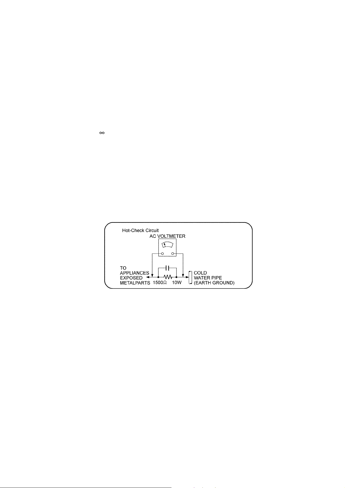
1. Plug the AC cord directly into the AC outlet. Do not use an isolation transformer for this check.
2. Connect a 1.5kΩ, 10 watts resistor, in parallel with a 0.15μF capacitors, between each exposed metallic part on the set and a
good earth ground such as a water pipe, as shown in Figure 1.
3. Use an AC voltmeter, with 1000 ohms/volt or more sensitivity, to measure the potential across the resistor.
4. Check each exposed metallic part, and measure the voltage at each point.
5. Reverse the AC plug in the AC outlet and repeat each of the above measurements.
6. The potential at any point should not exceed 0.75 volts RMS. A leakage current tester (Simpson Model 229 or e quivalent)
may be used to make the hot checks, leakage current must not exceed 1/2 milliamp. In case a measurement is outside of the
limits specified, there is a possibility of a shock hazard, and the equipment sho uld be repaired and rechecked before it is
returned to the customer.
Figure. 1
3
1.2. Before Repair and Adjustment
Disconnect AC power, discharge unit AC Capacitors as such C5700, C5702, C5703, C5705, and C5706 through a 1 0W, 1W resistor to ground.
Caution : DO NOT SHORT-CIRCUIT DIRECTLY (with a screwdriver blade, for instance), as this may destroy solid state devices.
After repairs are completed, restore power gradually using a variac, to avoid overcurrent.
• Current consumption at AC 220V - 240V, at 50Hz in NO SIGNAL mode (at volume min in FM Tuner mode) should be ~ 200 mA.
1.3. Protection Circuitry
The protection circuitry may have operated if either of the following conditions are noticed:
• No sound is heard when the power is turned on.
• Sound stops during a performance.
The function of this circuitry is to prevent circuitry damage if, for example, the positive and negative speaker connection wir es are
"shorted", or if speaker systems with an impedance less than the indicated rated impedance of the amplifier are used.
If this occurs, follow the procedure outlines below:
1. Turn off the power.
2. Determine the cause of the problem and correct it.
3. Turn on the power once again after one minute.
Note:
When the protection circuitry functions, the unit will not operate unless the power is first turned off and then on again.
1.4. Caution For Fuse Replacement
4
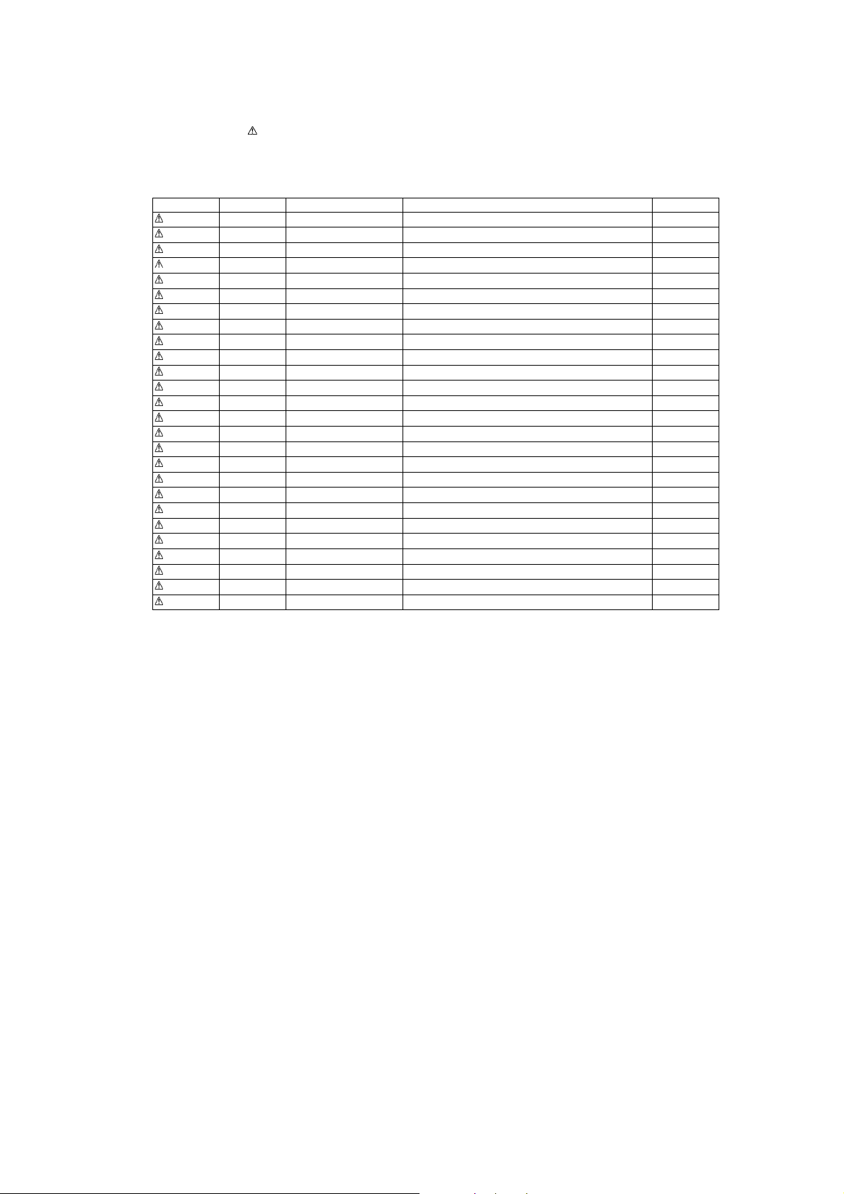
1.5. Safety Part Information
Safety Parts List:
There are special components used in this equipment which are important for safety.
These parts are marked by in the Schematic Diagrams, Exploded View & Replacement Parts List. It is essential that these
critical parts should be replaced with manufacturer’s specified parts to prevent shock, fire or other hazards. Do not modify the
original design without permission of manufacturer.
Safety Ref. No. Part No. Part Name & Description Remarks
17 RGR0431A-A REAR CABINET
23 RKM0677-S TOP CABINET
31 RMQ2034 PC SHEET
301 RAE1035Z-V TRAVERSE ASS’Y
A2 K2CQ2CA00002 AC CORD
A3 RQT9671-D O/I BOOK (Ge/It/Fr/Sp/Du/Da/Sw)
A3 RQT9672-E O/I BOOK (En/L.Sp/Po/C z/Fi)
PCB8 REP4812AF SMPS P.C.B (RTL)
DZ5701 ERZVA5Z471 ZNR
L5702 ELF15N035AN LINE FILTER
L5703 ELF19H010A LINE FILTER
T2900 G4D1A0000117 SWITCHING TRANSFORMER
T5701 ETS35BL166AD MAIN TRANSFORMER
PC5720 B3PBA0000503 PHOTO COUPLER
PC5760 B3PBA0000503 PHOTO COUPLER
F1 K5G312Y00007 FUSE
TH5702 D4CAA5R10001 THERMISTOR
P5701 K2AA2B000011 AC INLET
R5700 ERJ8GEYJ474V 470K 1/4W
R5701 ERJ8GEYJ474V 470K 1/4W
R5710 ERJ8GEYJ474V 470K 1/4W
C5700 F1BAF1020020 1000pF
C5702 F0CAF224A105 0.22uF
C5703 F0CAF224A105 0.22uF
C5705 F1BAF1020020 1000pF
C5706 F1BAF1020020 1000pF
5

2Warning
2.1. Prevention of Electro Static Discharge (ESD) to Electrostatically Sensi-
tive (ES) Devices
Some semiconductor (solid state) devices can be damaged easily by static electricity. Such components commonly are called Electrostatically Sensitive (ES) Devices. Examples of typical ES devices are integrated circuits and some field-effect transistors and
semiconductor “chip” components. The following techniques should be used to help reduce the incidence of component damage
caused by electrostatic discharge (ESD).
1. Immediately before handling any semiconductor compo nent or semicon ductor-equiped assembly, drain off any ESD on your
body by touching a known earth ground. Alternatively, obtain and wear a commercially available discharging ESD wrist strap,
which should be removed for potential shock reasons prior to applying power to the unit under test.
2. After removing an electrical assembly equiped with ES devices, pla ce the assembly on a condu ctive surface such as al umin-
ium foil, to prevent electrostatic charge build up or exposure of the assembly.
3. Use only a grounded-tip soldering iron to solder or unsolder ES devices.
4. Use only an anti-static solder remover device. Some solder removal devices not classified as “anti-static (ESD protected)” can
generate electrical charge sufficient to damage ES devices.
5. Do not use freon-propelled chemicals. These can generate electrical charges sufficient to damage ES devices.
6. Do not remove a replacement ES device from its protective package until immediately before you are ready to install it. (Most
replacement ES devices are packaged with leads electrically shorted together by conductive foam, aluminium foil or comparable conductive material).
7. Immediately before removing the protective material from the leads of a replacement ES device, touch the protective material
to the chassis or circuit assembly into which the device will be installed.
Caution :
Be sure no power is applied to the chassis or circuit, and observe all other safety precautions.
8. Minimize bodily motions when handling unpackaged replacement ES devices. (Otherwise harmless motion such as the
brushing together of your clothes fabric or the lif ting of your foot from a carpeted floor can generate static electricity (ESD) sufficient to damage an ES device).
6
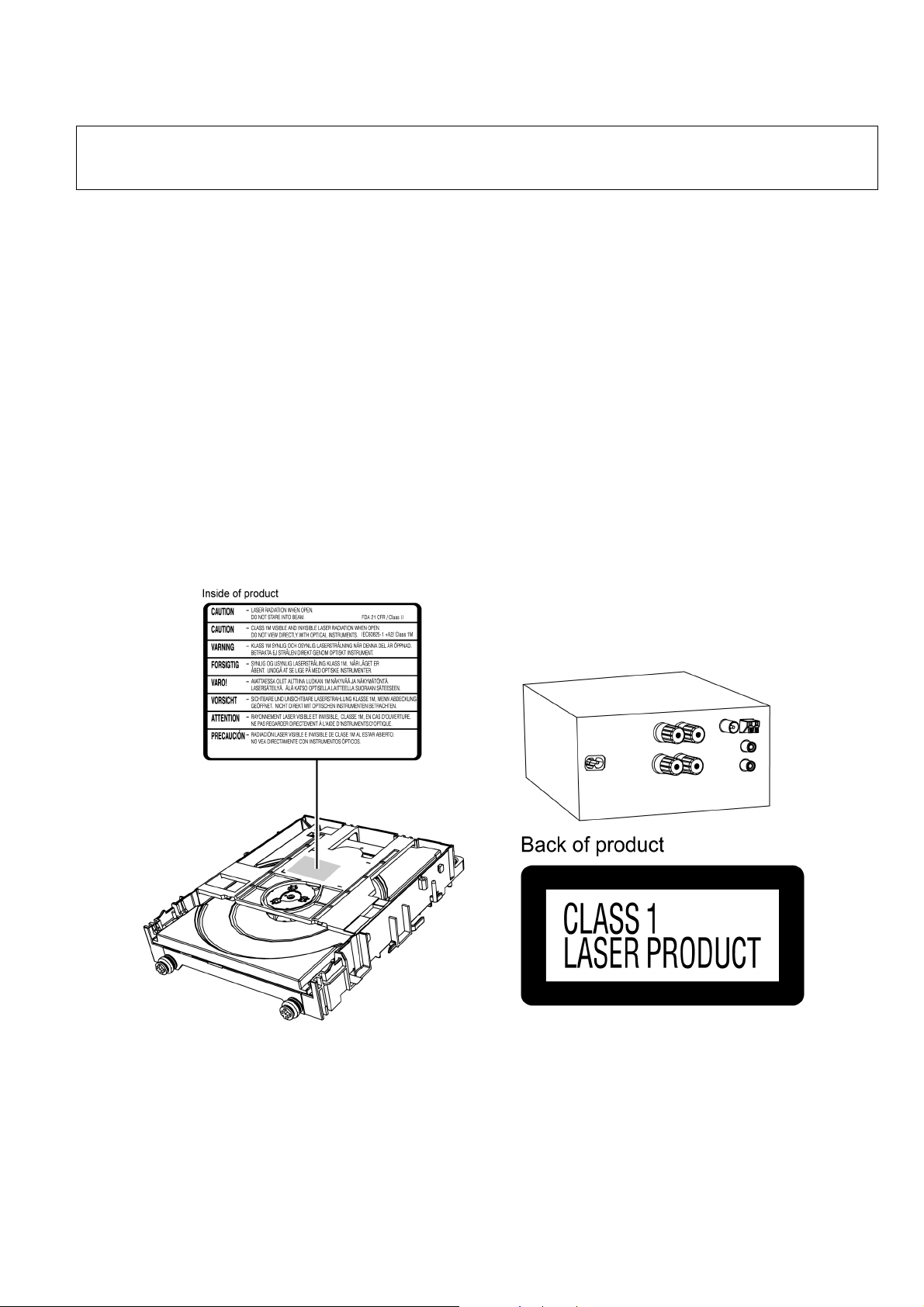
2.2. Precaution of Laser Diode
CAUTION!
THIS PRODUCT UTILIZES A LASER.
USE OF CONTROLS OR ADJUSTMENTS OR PERFORMANCE OF PROCEDURES OTHER THAN THOSE SPECIFIED HEREIN MAY RESULT
IN HAZARDOUS RADIATION EXPOSURE.
Caution:
This product utilizes a laser diode with the unit turned "on", invisible laser radiation is emitte d from the pickup lens.
Wavelength: 790 nm (CD)
Maximum output radiation power from pickup: 100 μW/VDE
Laser radiation from the pickup unit is safety level, but be sure the followings:
1. Do not disassemble the pickup unit, since radiation from exposed laser diode is dangerous.
2. Do not adjust the variable resistor on the pickup unit. It was already adjusted.
3. Do not look at the focus lens using optical instruments.
4. Recommend not to look at pickup lens for a long time.
ACHTUNG :
Dieses Produkt enthält eine Laserdiode. Im eingeschalteten Zustand wird unsichtbare Laserstrahlung von der Lasereinhei tadgestrahit.
Wellenlänge : 790nm (CD)
Maximale Strahlungsleistung der Lasereinheit :100 μW/VDE
Die Strahlung an der Lasereinheit ist ungefährlich, wenn folgende Punkte beachtet werden:
1. Die Lasereinheit nicht zerlegen, da die Strahlung an der freigelegten Laserdiode gefährlich ist.
2. Den werkseitig justierten Einstellregler der Lasereinhit nicht verstellen.
3. Nicht mit optischen Instrumenten in die Fokussierlinse blicken.
4. Nicht über längere Zeit in die Fokussierlinse blicken.
7

2.3. Service caution based on Legal restrictions
2.3.1. General description about Lead Free Solder (PbF)
The lead free solder has been used in the mounting process of all electrical comp onents on the printed circuit boards us ed for this
equipment in considering the globally environmental conservation.
The normal solder is the alloy of tin (Sn) and lead (Pb). On the other hand, the lead free solder is the alloy mainly consists of tin
(Sn), silver (Ag) and Copper (Cu), and the melting point of the lead free solder is higher approx.30 degrees C (86°F) more than that
of the normal solder.
Definition of PCB Lead Free Solder being used
The letter of “PbF” is printed either foil side or components side on the PCB using the lead free solder.
(See right figure)
Service caution for repair work using Lead Free Solder (PbF)
• The lead free solder has to be used when repairing the equipment for which the lead free solder is used.
(Definition: The letter of “PbF” is printed on the PCB using the lead free solder.)
• To put lead free solder, it should be well molten and mixed with the original lead free solder.
• Remove the remaining lead free solder on the PCB cleanly for soldering of the new IC.
• Since the melting point of the lead free solder i s higher than that of the normal lead solder, it takes the longer time to melt the
lead free solder.
• Use the soldering iron (more than 70W) e quipped with the tempe rature control after setting the te mperature at 350±30 degrees
C (662±86°F).
Recommended Lead Free Solder (Service Parts Route.)
• The following 3 types of lead free solder are available through the service parts route.
RFKZ03D01K-----------(0.3mm 100g Reel)
RFKZ06D01K-----------(0.6mm 100g Reel)
RFKZ10D01K-----------(1.0mm 100g Reel)
Note
* Ingredient: Tin (Sn), 96.5%, Silver (Ag) 3.0%, Copper (Cu) 0.5%, Cobalt (Co) / Germanium (Ge) 0.1 to 0.3%
8
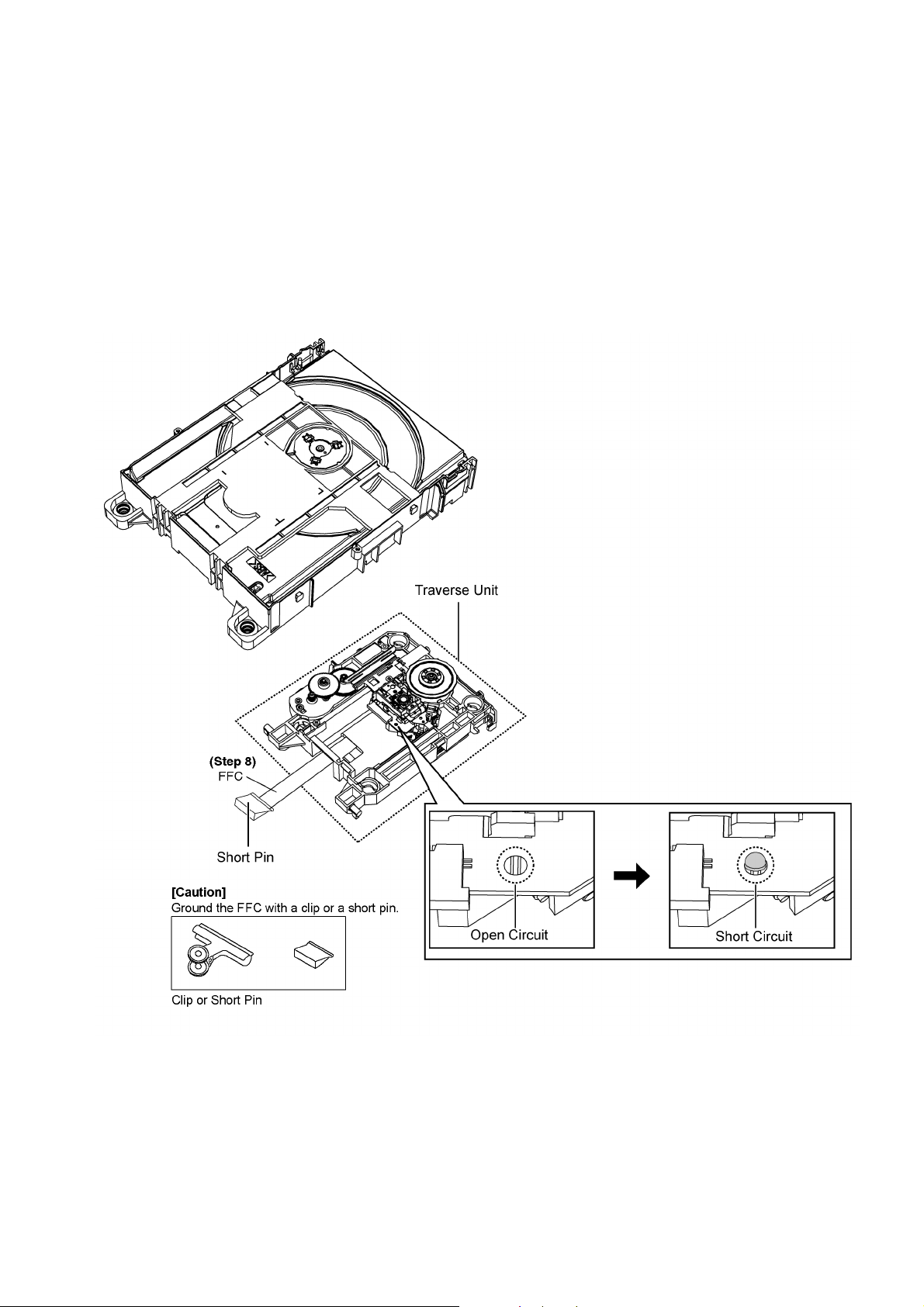
2.4. Handling Precaution for Traverse
The laser diode in the optical pickup unit may break down due to static electricity of clothes or human b ody. Spe cial care must be
taken avoid caution to electrostatic breakdown when servicing and handling the laser diode in the Traverse.
2.4.1. Cautions to Be Taken in Handling the Optical Pickup Unit
The laser diode in the optical pickup unit ma y be damaged due to electrostatic discharge generating from clothes or human body.
Special care must be taken avoid caution to electrostatic discharge damage when servicing the laser diode.
1. Do not give a considerable shock to the optical pickup unit as it has an extremely high-precise structure.
2. To prevent the laser diode from the electrostatic discharge d amage, the flexible cable of the optical pickup unit removed
should be short-circuited with a short pin or a clip.
3. The flexible cable may be cut off if an excessive force is applied to it. Use caution when handling the flexible cable.
4. The antistatic FPC is connected to the new optical pickup unit. After replacing the optical pickup unit and connecting the flexible cable, cut off the antistatic FPC.
9
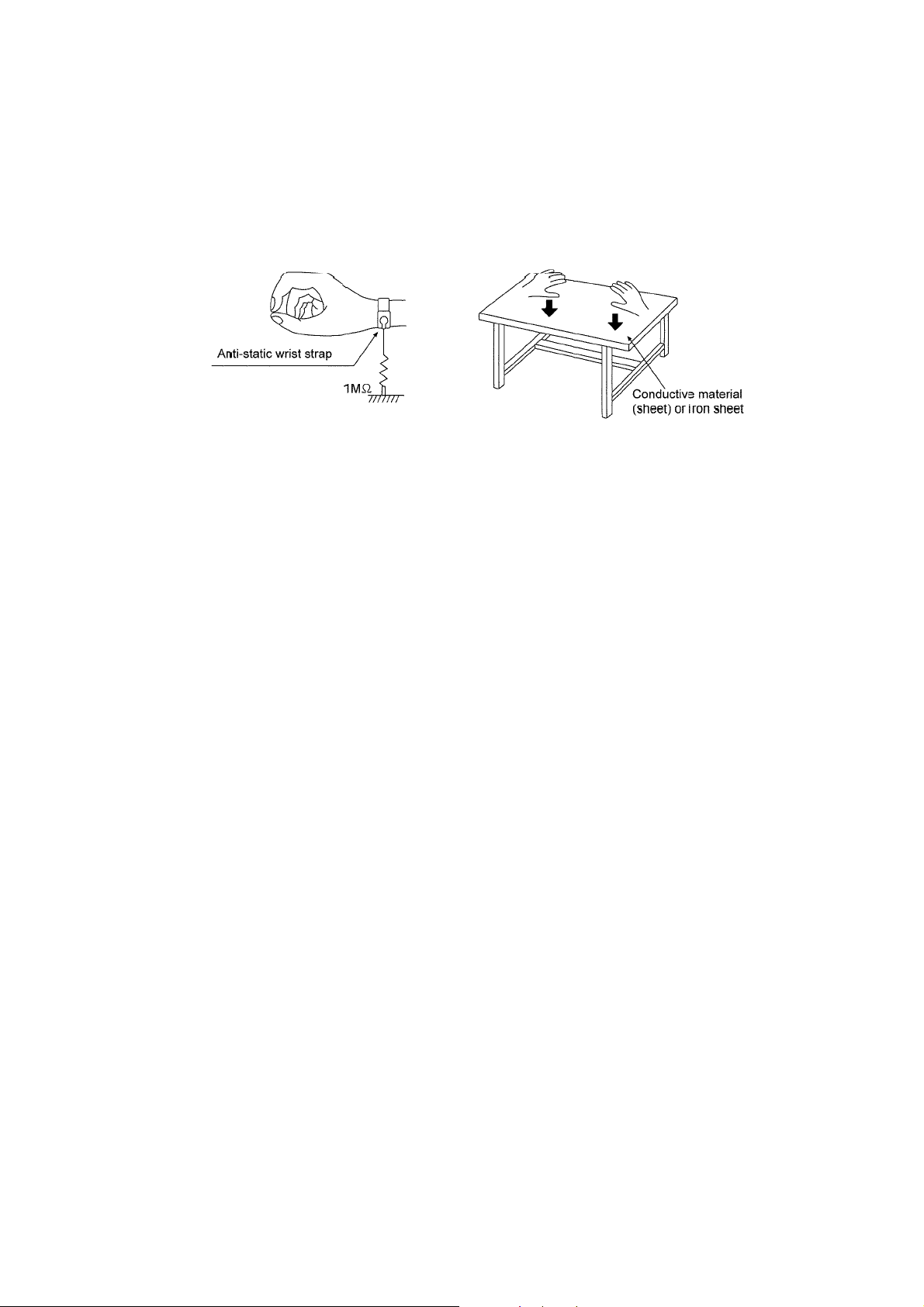
2.4.2. Grounding for electrostatic breakdown prevention
Some devices such as the CD player use the optical pickup (laser diode) and the optical pickup will be damaged by static electricity
in the working environment. Proceed servicing works under the working environment where grounding works is completed.
2.4.2.1. Worktable grounding
1. Put a conductive material (sheet) or iron sheet on the area where the optical picku p is placed , and ground the sheet.
2.4.2.2. Human body grounding
1. Use the anti-static wrist strap to discharge the static electricity form your body.
10

3 Service Navigation
3.1. Service Information
This service manual contains technical information which will allow service personnel’s to understand and service this model.
Please place orders using the parts list and not the drawing reference numbers.
If the circuit is changed or modified, this information wil l be fol lowed by supp lement service ma nual to be filed with original servic e
manual.
• Micro-processor:
1) The following components are supplied as an assembled part.
- Micro-processor IC, (IC6003) (RFKWMPMX5EG)
11

4 Specifications
Q Amplifier Section
RMS Output Power Stereo Mode
Front Ch (both ch driven) 60 W per channel (3 Ω), 1 kHz,
10% THD
Total RMS Stereo mode power 120 W
Q Tuner section
Preset station FM 30 stations
AM 15 stations
Frequency modulation (FM)
Frequency range 87.50 MHz to 108.00 MHz
(50 kHz step)
Antenna terminals 75 Ω (unbalanced)
Amplitude modulation (AM)
Frequency range 522 kHz to 1629 kHz (9 kHz step)
520 kHz to 1630 kHz
(10 kHz step)
Q Terminals section
USB port
USB standard USB 2.0 full speed
Media file format support MP3 (*.mp3)
USB device file system FAT12, FAT16, FAT32
USB port power 500 mA (max)
Headphones jack
Terminal Stereo, Ø3.5 mm jack
AUX input (rear) RCA pin jack
• Specifications are subject to change without notice. Mass and
dimensions are approximate.
• Total harmonic distortion is measured by the digital spectrum analyzer.
Q System : SC-PMX5EG-S Music center: SA-PMX5EG-S
Speaker: SB-PMX5EG-K
Q Disc Section
Disc played [8 cm or 12 cm]
CD, CD-R/RW (CD-DA, MP3*)
Pick up
Wavelength 790 nm (CD)
Laser power CLASS 1
Audio output (Disc)
Number of channels 2 ch (FL, FR)
FL = Front left channel
FR = Front right channel
*MPEG-1 Layer 3, MPEG-2 Layer 3
Q Speaker Section
Type 3 way, 3 speaker system
Speaker unit(s)
Woofer 14 cm cone type
Tweeter 1.9 cm soft dome type
Super tweeter 1.5 cm piezo type
Impedance 3 Ω
Output sound pressure 81 dB/W (1 m)
Frequency range 41 Hz to 43 kHz (–16 dB)
48 Hz to 36 kHz (–10 dB)
Dimensions (W x H x D) 161 mm x 238 mm x 262 mm
Mass 2.6 kg
Q General
Power supply AC 220 V to 240 V, 50 Hz
Power consumption 40 W
Dimensions (W x H x D) 210 mm x 120 mm x 266 mm
Mass 3 kg
Operating temperature range 0 °C to +40 °C
Operating humidity range 35% to 80 % RH
Power consumption in standby mode: Approx. 0.4 W
(approximate)
(bass reflex)
(no condensation)
12
5 General/Introduction
5.1. CD playback operations
13
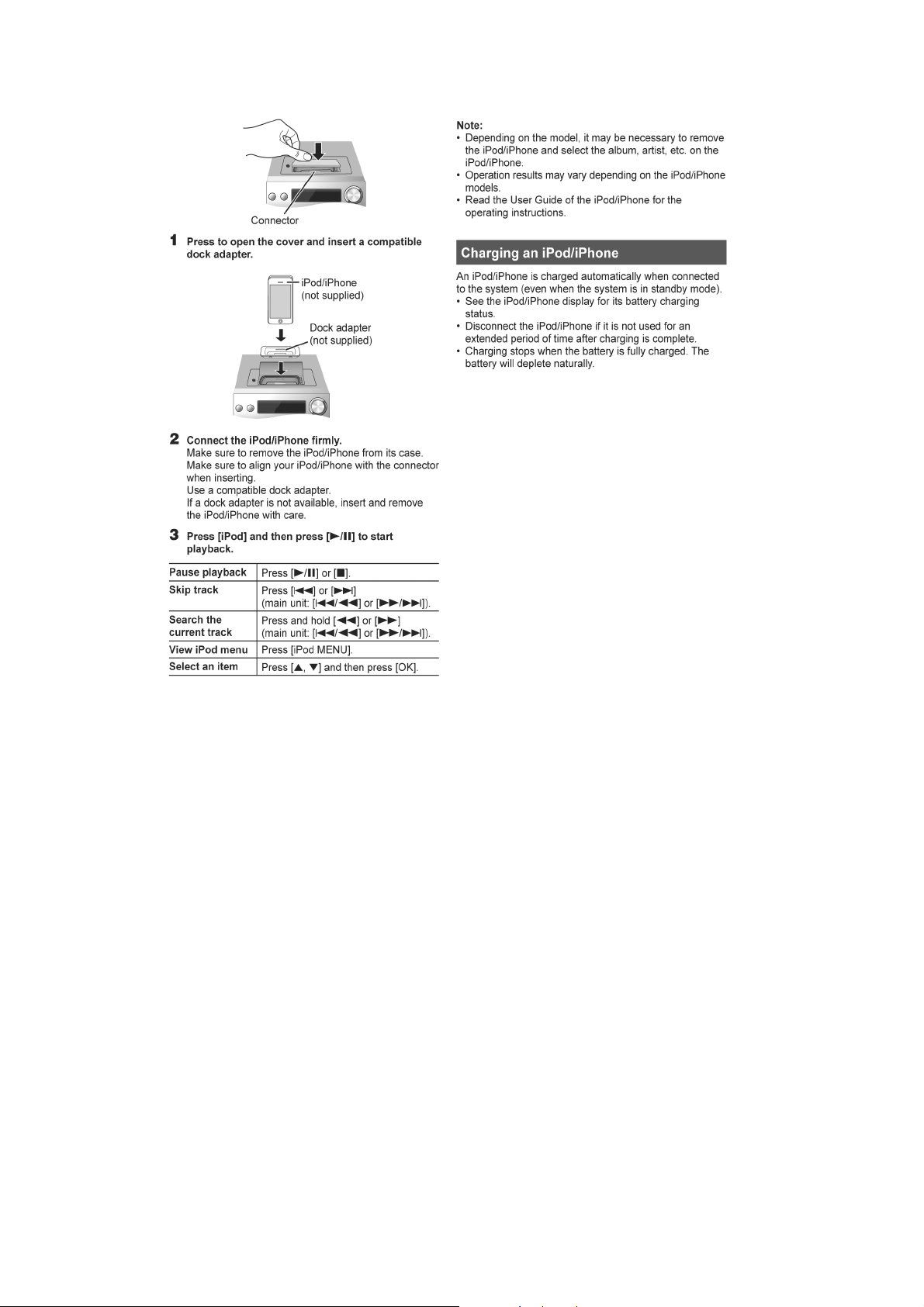
5.2. iPod/iPhone playback operations
Compatibility CD, iPod/iPhone & USB
• For compatibility of CD, iPod/iPhone & USB please refer to Operating Instructions.
14
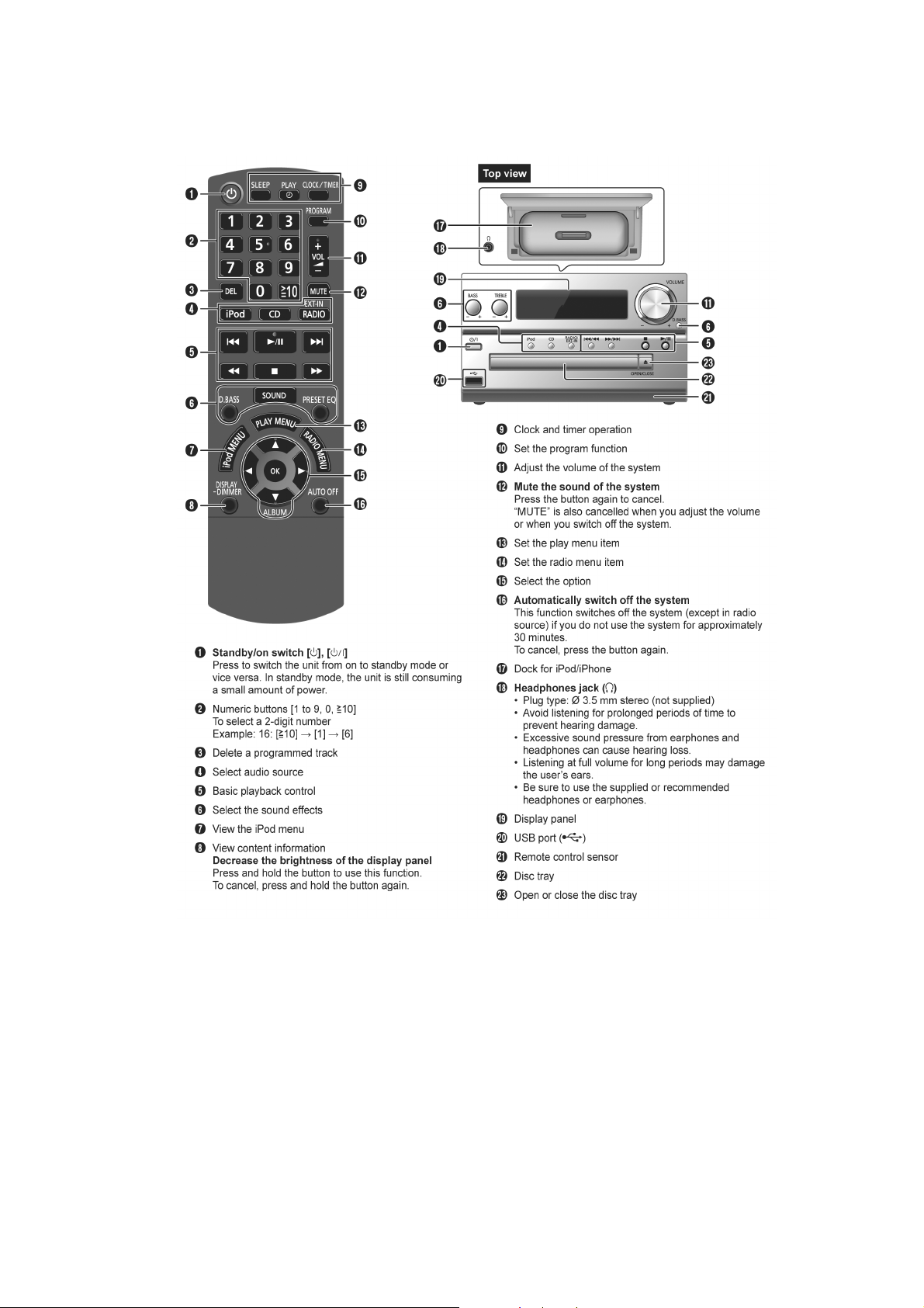
6 Location of Controls and Components
6.1. Main Unit & Remote Control Key Button Operations
15
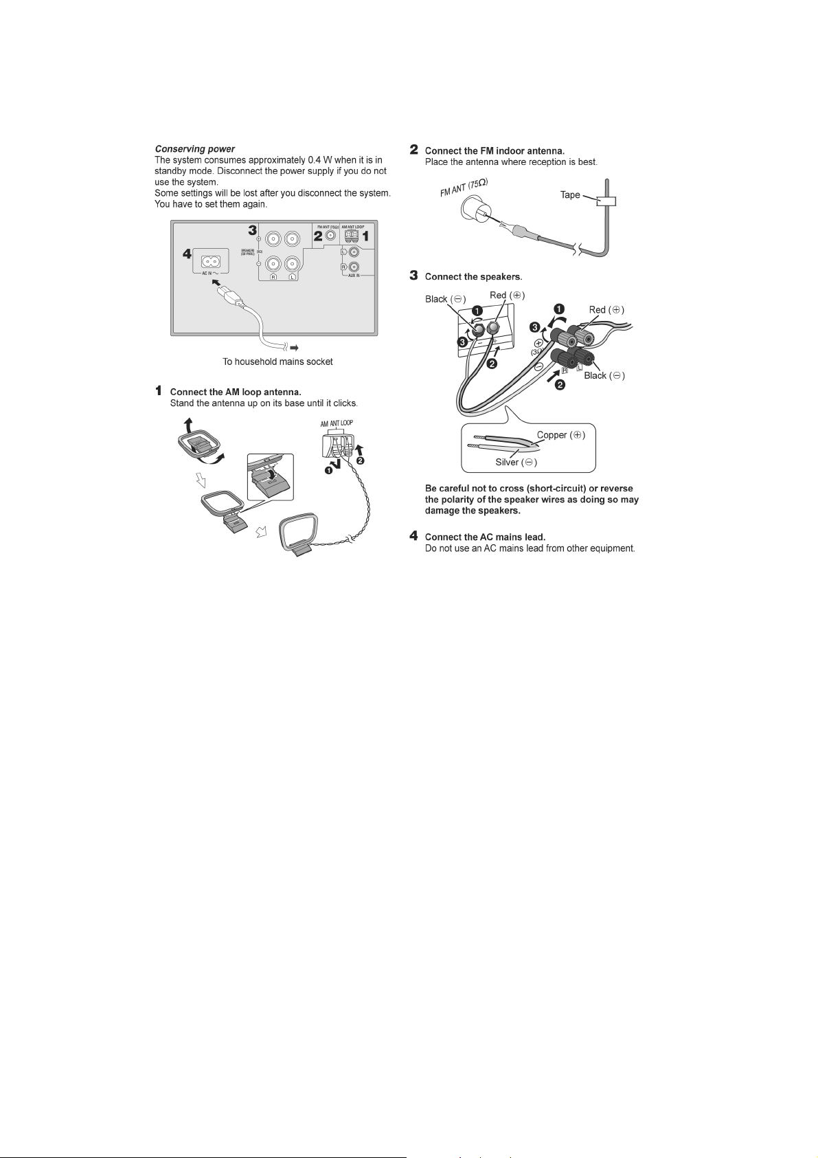
7 Installation Instructions
7.1. Connections
16
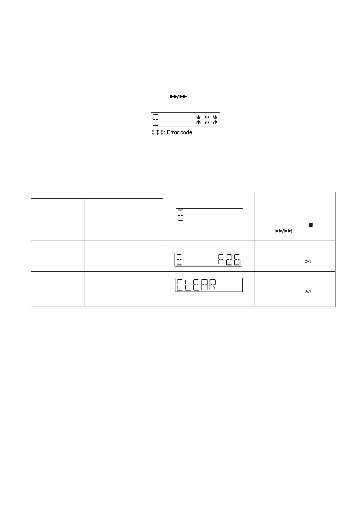
8 Service Mode
Self Diagnostic Mode To enter into self diagnostic
checking
Item
FL display Key operation
Mode name Description
Error code information
Delete Error code
Example:
System will perform a check on
any unusual/error code from the
memory
To clear the stored in memory
(EEPROM IC)
Step 1 : Select CD mode
(Ensure no disc is inserted).
Step 2 : Press and hold [ ] follow by
[ ] on main unit for 2
second .
Step 1 : In self diagnostic mode,
Press [STOP] on main unit.
To exit, press [TA] on main
unit or remote control.
Step 1 : In self diagnostic mode,
Press [0] on remote control.
To exit, press [TA] on main
unit or remote control.
This unit is equipped with features of self diagnostic & doctor mode setting for checking the functions & reliability.
8.1. Self Diagnostic Mode
Here is the procedures to enter into Self Diagnostic Mode.
Step 1 : Turn on the unit.
Step 2 : Select CD mode.
Step 3 : Press and hold [Q] button for 2 seconds follow by [ ] on the unit.
Step 4 : The display show as follow.
To exit the Self Diag nostic Mode
Use either one of the following methods to cancel the Self Diagnostic Mode.
• Press the power button on the main unit or using the remote control.
• Unplug the AC cord.
8.1.1. Self Diagnostic Table
17
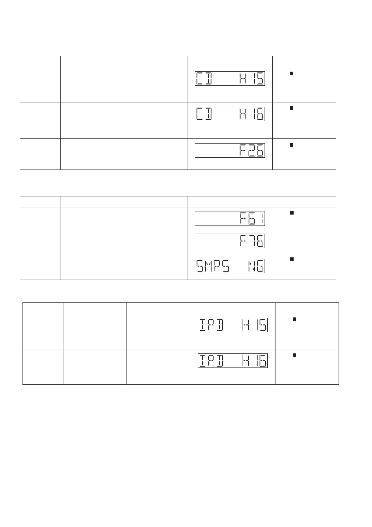
8.2. Self Diagnostic Function Error Code
of error Automatic FL Display Remarks
CD H15 CD Open Abnormal During operation
POS_SW_R On fail to be
detected within 4 sec. Error
No. shall be clear by force
or during cold start.
Press [
] on main unit for
next error.
CD H16 CD Closing Abnormal During operation
POS_SW_CEN On fail to
be detected within 4 sec.
Error No. shall be clear by
force or during cold start.
Press [
] on main unit for
next error.
F26 Communication between
CD servo LSI and micro-p
abnormal.
During switch to CD function, if SENSE = “L” within
failsafe time of 20ms.
Press [
] on main unit for
next error.
Error Code Diagnostic Contents Description of error
of error Automatic FL Display Remarks
F61/F76 Power Amp IC output
SMPS NG Checking SMPS Type
abnormal
During power-on, PDET1,
SMPS type and REGION
not match.
The unit will shutdown.
PDET2 & MAINV_DET /
TEMP_DET is “L” after 1
sec.
Press [
] on main unit for
next error.
Press [
] on main unit for
next error.
Error Code Diagnostic Contents Description of error
of error Automatic FL Display Remarks
IPD H15 iPod Open Abnormal During operation
POS_SW_L On fail to be
detected within 3 sec. Error
No. shall be clear by force
or during cold start.
Press [
] on main unit for
next error.
IPD H16 iPod Closing Abnormal During operation
POS_SW_CEN On fail to
be detected within 3 sec.
Error No. shall be clear by
force or during cold start.
Press [
] on main unit for
next error.
Error Code Diagnostic Contents Description of error
8.2.1. CD Mechanism Error Code Table
8.2.2. Power Amp Error Code Table
8.2.3. iPod Error Code Table
18
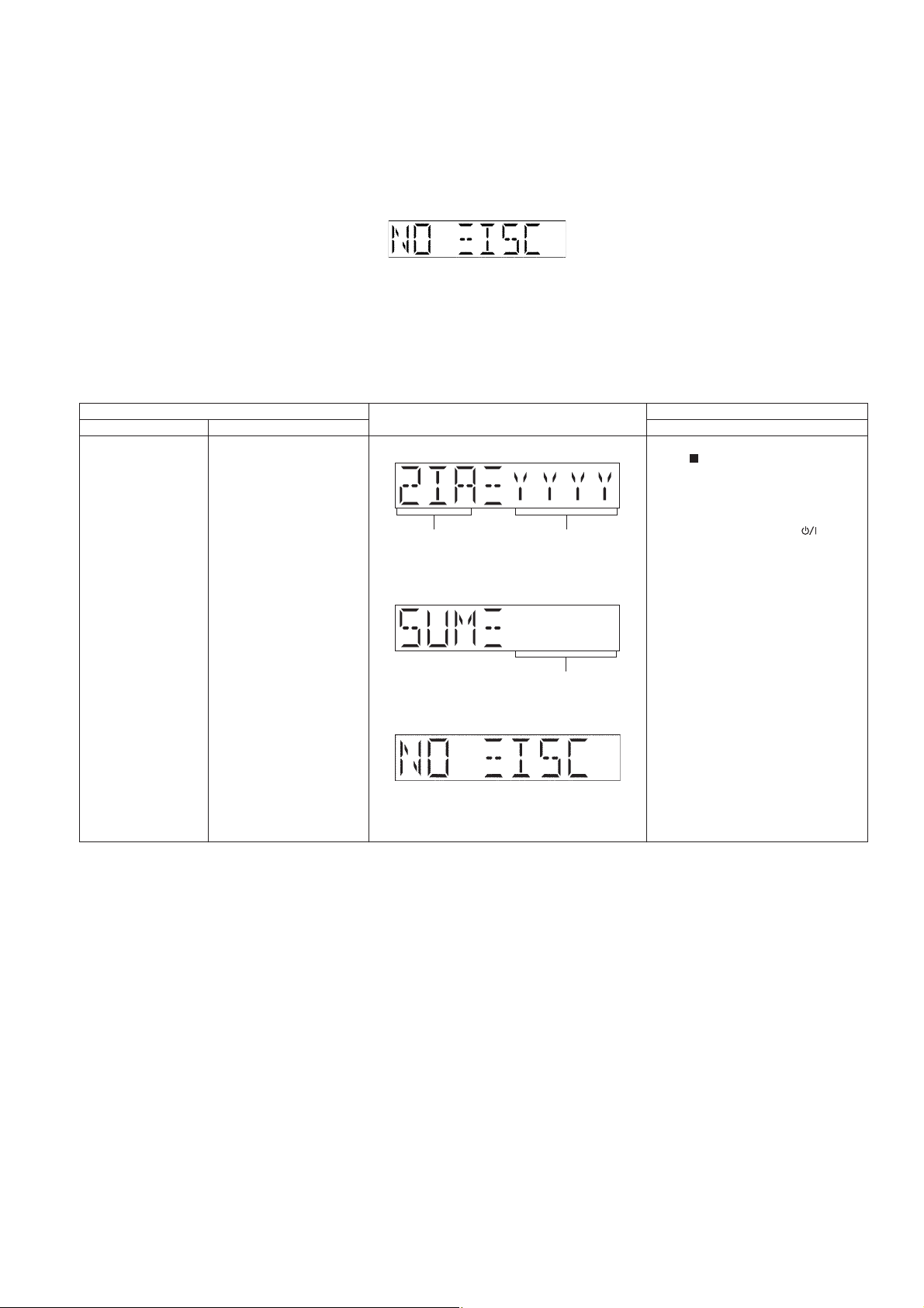
8.3. Doctor Mode Table
Item
FL Display
Key Operation
Mode Name Description Front Key
Doctor Mode To enter into Doctor Mode
for checking of various
items and displaying
EEPROM and firmware version.
Note: The micro-processor
version as shown is an
example. It will be revise
when there is an updates.
FL Display sequence Display 1 ¡ 2
(Display 1)
Checksum : (Condition 1)
(Display 2)
The Checksum of EEPROM and firmware
version will be display for 2 sec.
In any mode:
Press
[ ]
button on main unit follow by
[4] & then [7] on the remote control.
To exit Doctor Mode, press
[TA]
button
on main unit or on the remote control.
Version Display
(DEC)
Check sum
(HEX)
No Rom correction
Note : To enter the Doctor Mode, please use HC35 remote control.
Here is the procedures to enter into Doctor Mode.
Step 1 : Turn on the unit.
Step 2 : Select CD mode.
Step 3 : Pressing and hold [Q] on main unit then press [4] follow by [7] using the remote control.
Step 4 : The display show as follow.
To exit the Doc tor mo de
Use either one of the following methods to cancel the Doctor mode.
• Press the power button of the unit or using the remote control.
• Unplug the AC cord.
8.3.1. Doctor Mode Table 1
19
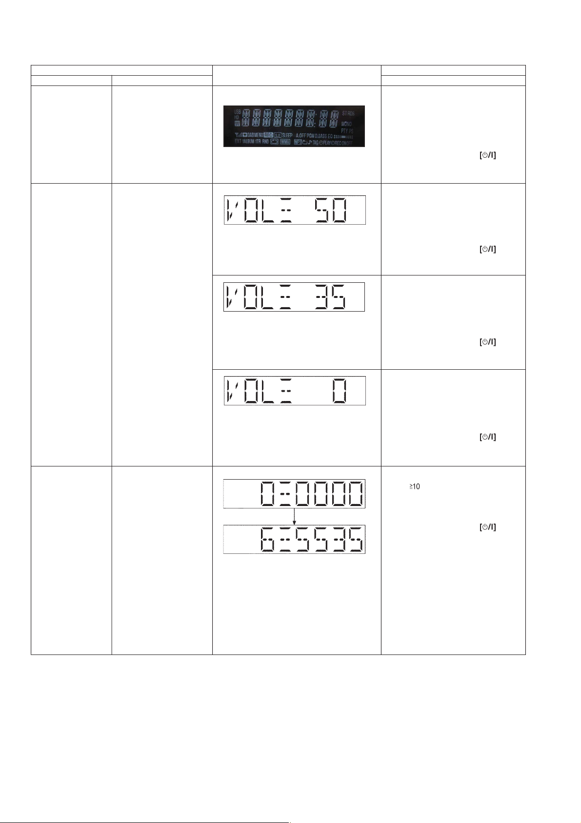
8.3.2. Doctor Mode Table 2
Item
FL Display
Key Operation
Mode Name Description
Front Key
FL Display Test To check the FL segments
display (All segments will
light up)
In Doctor Mode:
Press [1] button on the remote control.
To cancel, press [0] button on remote
control. It returns Doctor Mode.
To cancel, press [0] button on remote
control. It returns Doctor Mode.
To cancel, press [0] button on remote
control. It returns Doctor Mode.
To cancel, press [0] button on remote
control. It returns Doctor Mode.
To exit Doctor Mode, press button on main unit or on the remote control.
Volume Setting In Doctor Mode:
Press [7] button on the remote control.
In Doctor Mode:
Press [8] button on the remote control of.
In Doctor Mode:
Press [9] button on the remote control of5.
Mecha Sliding Panel
Reliability
In Doctor Mode:
Press [ ] follow by [2] & then [1]
button on the remote control.
To cancel, press [0] button on remote
control. It returns Doctor Mode.
To exit Doctor Mode, press button on main unit or on the remote control.
To exit Doctor Mode, press button on main unit or on the remote control.
To exit Doctor Mode, press button on main unit or on the remote control.
To exit Doctor Mode, press button on main unit or on the remote control.
To check the operation of
sliding Panel.
Sequence as follow :
1. CD Door set to CLOSE
position.
2. CD Door move to the left
(CD Open direction) and
stop at LEFT position for 1
sec.
3. CD Door move to the
right (CD Close direction)
and stop at CLOSE position
for 1 sec.
4. All the process above is
considered as 1 cycle. Step
(2) ~ (3) will repeat; Cycle
Counter display increase
every 1 cycle completed.
Refer to 8.3.5 for more
information
To check for preset volume
setting
Note : In tuner mode this
function is not possible
20
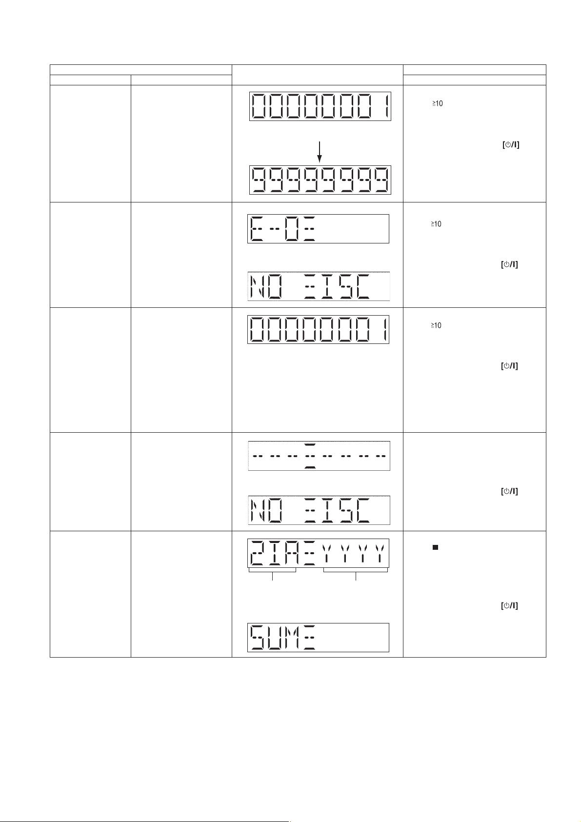
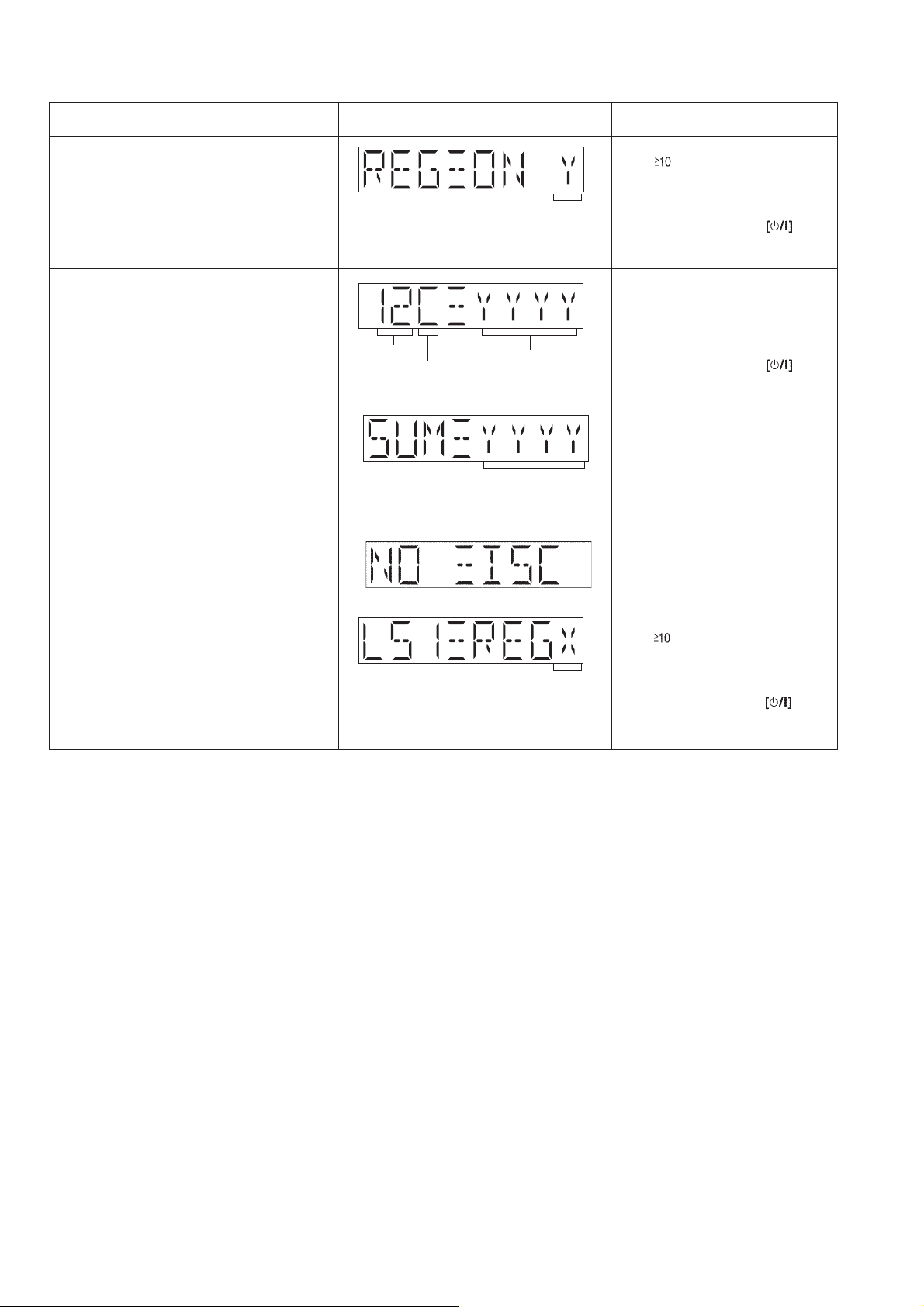
8.3.3. Doctor Mode Table 3
Item FL Display Key Operation
Mode Name Description Front Key
Cold Start
The [NO DISC] display will appear after 2s,
To display result of self
adjustment for CD.
The [NO DISC] display will appear after 3s,
In Doctor Mode:
Press [ ] follow by [1] & then [4]
button on the remote control.
To cancel, press [0] button on remote
control. It returns Doctor Mode.
To exit Doctor Mode, press button on main unit or on the remote control.
In Doctor Mode:
Press [ ] follow by [1] & then [5]
button on the remote control.
To cancel, press [0] button on remote
control. It returns Doctor Mode.
To exit Doctor Mode, press button on main unit or on the remote control.
In Doctor Mode:
Press [SLEEP] button on remote
control.
To cancel, press [0] button on remote
control. It returns Doctor Mode.
To exit Doctor Mode, press button on main unit or on the remote control.
To cancel, press [0] button on remote
control. It returns Doctor Mode.
To exit Doctor Mode, press button on main unit or on the remote control.
CD Self-Adjusment
Display
CD Combination Test To check the open/close
operation & inner outer disc
access operation.
1. It fails when CD
open/close is not completed
by 4s.
2. The disc access fails in
10s.
3. The traverse is out of
focus for more than 2s.
Refer to 8.3.7 for more
information
To activate cold start upon
next power up.
(Backup data are initialized)
EEPROM Checksum To check sum of EEPROM
for a simplifield ROM
correction.
1. When EEPROM is not
detected, the only micro-p’s
version shall be displayed
without an EEPROM’s
check sum
In any mode:
Press
[ ]
button on main unit follow by
[4] & then [7] on the remote control.
EEPROM not detected only firmware is display
Version Display
(DEC)
Check sum
(HEX)
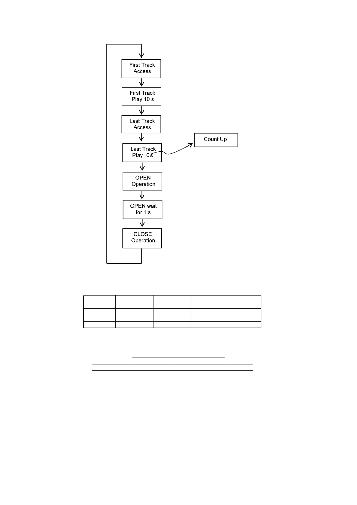
CD Traverse Test
Mode
To check for the traverse unit
operation. In this mode, the
first & last track is access &
read. (TOC). It fails when
TOC is not completed by 10s
or the traverse is out of
focus. for more than 2s
Refer to 8.3.6 for more
information
In Doctor Mode:
Press [ ] follow by [1] & then [2]
button on the remote control.
To cancel, press [0] button on remote
control. It returns Doctor Mode.
To exit Doctor Mode, press button on main unit or on the remote control.
The counter will increment by 1 until reach
99999999
21
8.3.4. Doctor Mode Table 4
Item FL Display Key Operation
Mode Name Description Front Key
In Doctor Mode:
Press [ ] follow by [1] & then [6]
button on the remote control.
To cancel, press [0] button on remote
control. It returns Doctor Mode.
To exit Doctor Mode, press button on main unit or on the remote control.
In Doctor Mode:
Press [4] button on the remote control.
To cancel, press [0] button on remote
control. It returns Doctor Mode.
To exit Doctor Mode, press button on main unit or on the remote control.
Region Checking
To check Region setting of
unit.
Refer to 8.3.8 for the Region
Setting destination
Region Setting destination
CD LSI 947 Version
Check
To check CD LSI Version
No. & checksum correction
Model setting
To check Model Setting.
Refer to 8.3.9 for the Model
Setting
Year of sales
ROM type
Running version
number
In Doctor Mode:
Press [ ] follow by [1] & then [8]
button on the remote control.
To cancel, press [0] button on remote
control. It returns Doctor Mode.
To exit Doctor Mode, press button on main unit or on the remote control.
Model Setting
Check sum display (HEX)
The display will appear after 2s,
The [NO DISC] display will appear after 2s,
22
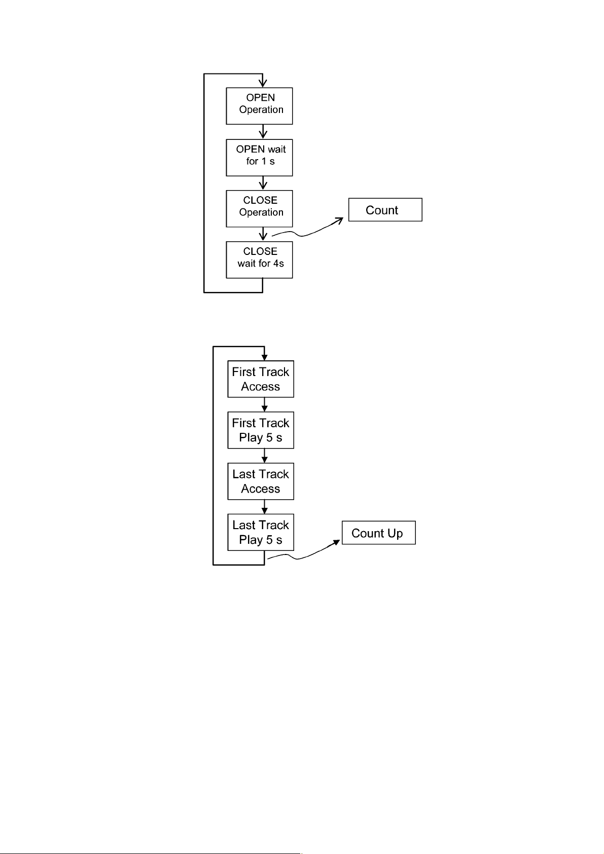
8.3.5. Mecha Sliding Panel Reliability
8.3.6. CD T raverse Test (For CD)
23
8.3.7. CD Combination Test (For CD)
8.3.8. Region Check Table (For Tuner)
Region Model Series Country
2 (D) PMX5 Japan Japan
4 PMX5 EG S.America (except Argentina)
5 PMX5 DBEB UK
9 PMX5 DBGN Oceania
8.3.9. Model setting
Region No. Function Model
With iPod With Shock Proof
S0 O O PMX5
24

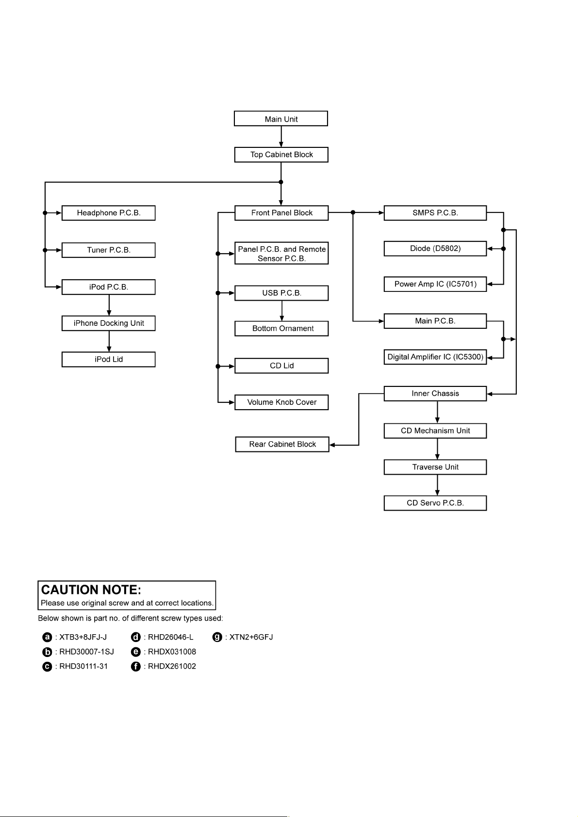
9 Disassembly and Assembly Instructions
Caution Note:
• This section describes the disassembly and/or assembly procedures for all major printed circuit boards & main components for the unit. (You may refe r to the se ctio n of “Main compon ents and P.C.B Locations” as de scr ibed in the servic e
manual)
• Before carrying out the disassembly process, please ensure all the safety precautions & procedures are followed.
• During the disassembly and/or assembly p rocess, please handle with care as there may be chassis components with
sharp edges.
• Avoid touching heatsinks due to its high temperature after prolong use. (See caution as described below)
• During disassembly and assembly, please ensure proper service tools, equipments or jigs is being used.
• During replacement of component parts, please refer to the section of “Replacement Parts List” as described in the service manual.
• Select items from the following indexes when disassembly or replacement are required.
• Disassembly of Top Cabinet Block
• Disassembly of Headphone P.C.B.
• Disassembly of iPod P.C.B.
• Disassembly of iPhone Docking Unit
• Disassembly of iPod Lid
• Disassembly of Front Panel Block
• Disassembly of Panel P.C.B. and Remote Sensor P .C.B.
• Disassembly of USB P.C.B.
• Disassembly of CD Lid
• Replacement of Bottom Ornament
• Disassembly of Volume Knob Cover
• Disassembly of SMPS P.C.B.
• Replacement of Diode (D5802)
• Replacement of Power Amp IC (IC5701)
• Disassembly of Main P.C.B.
• Replacement of Digital Amplifier IC (IC5300)
• Disassembly of Inner Chassis
• Replacement of Traverse Unit
• Disassembly of Rear Cabinet Block
• Disassembly of Tuner P.C.B.
25
9.1. Disassembly flow chart
The following chart is the procedure for disassembling the casing and inside parts for internal inspection when carrying out the servicing.
To assemble the unit, reverse the steps shown in the chart below.
9.2. Types of Screws
26
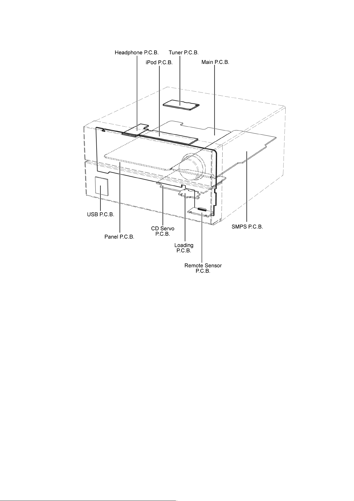
9.3. Main Parts Location Diagram
27
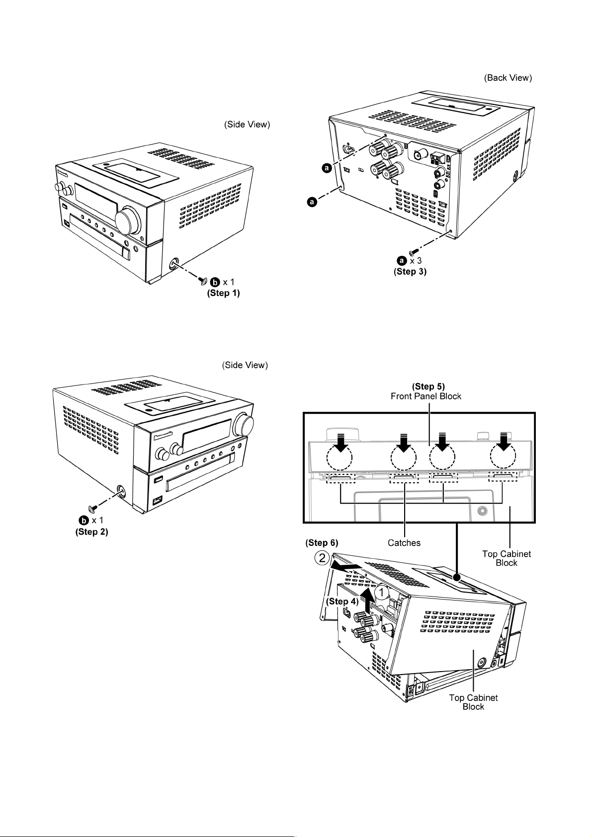
9.4. Disassembly of Top Cabinet Block
Step 1 : Remove 1 screw.
Step 2 : Remove 1 screw.
Step 3 : Remove 3 screws.
Step 4 : Lift up the Top Cabinet Block.
Step 5 : Press the Front Panel Assembly downwards to release
the catches.
Step 6 : Remove the Top Cabinet Block as shown.
Caution : During assembling, ensure the Top Cabinet
Block is inserted fully into the Front Panel Block.
28
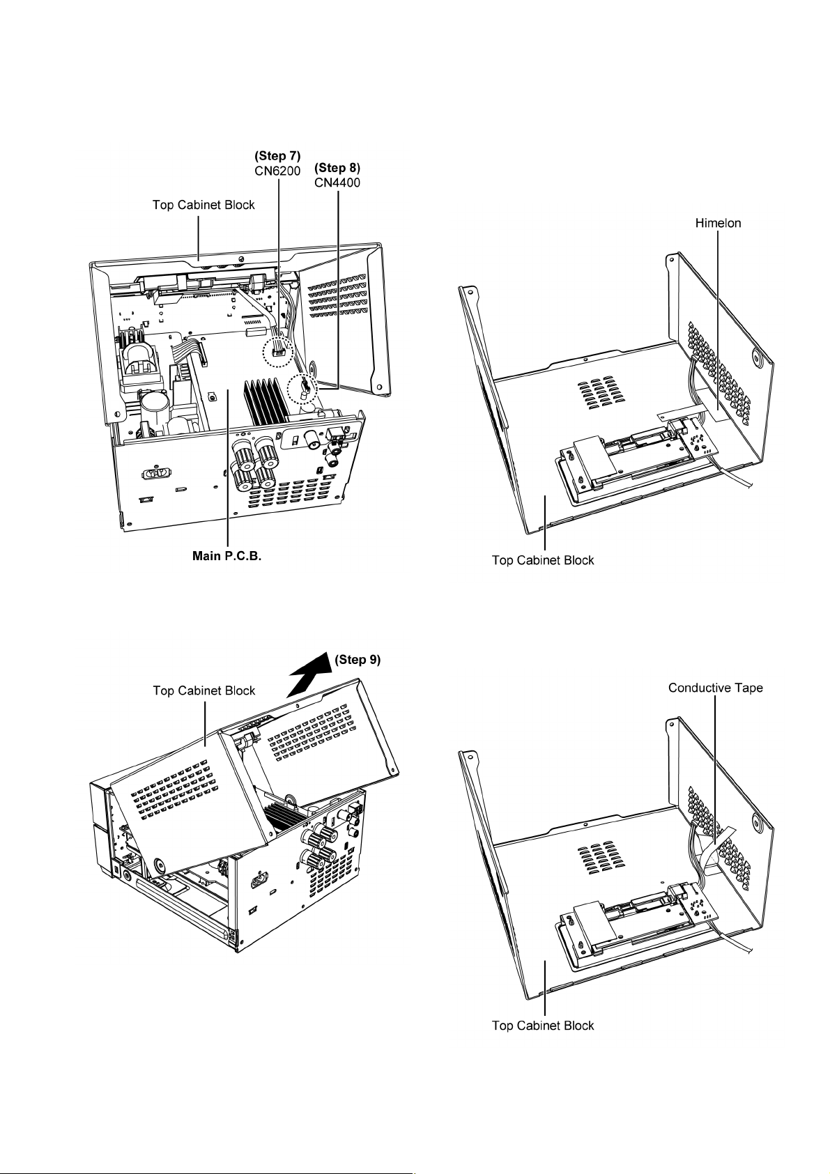
Step 7 : Detach 5P Cable Wire at connector (CN6200) on Main
P.C.B..
Step 8 : Detach 5P Cable Wire at connector (CN4400) on Main
P.C.B..
9.5. Disassembly of Headphone P.C.B.
• Refer to “Disassembly of Top Cabinet Block”.
Step 1 : Lift up the Him el on.
Caution : Replace the Himelon if torn during disassem-
bling.
Step 9 : Remove the Top Cabinet Block.
Step 2 : Lift up the Conductive Tape .
Caution : Replace the Conductive Tape if torn during disas-
sembling.
29
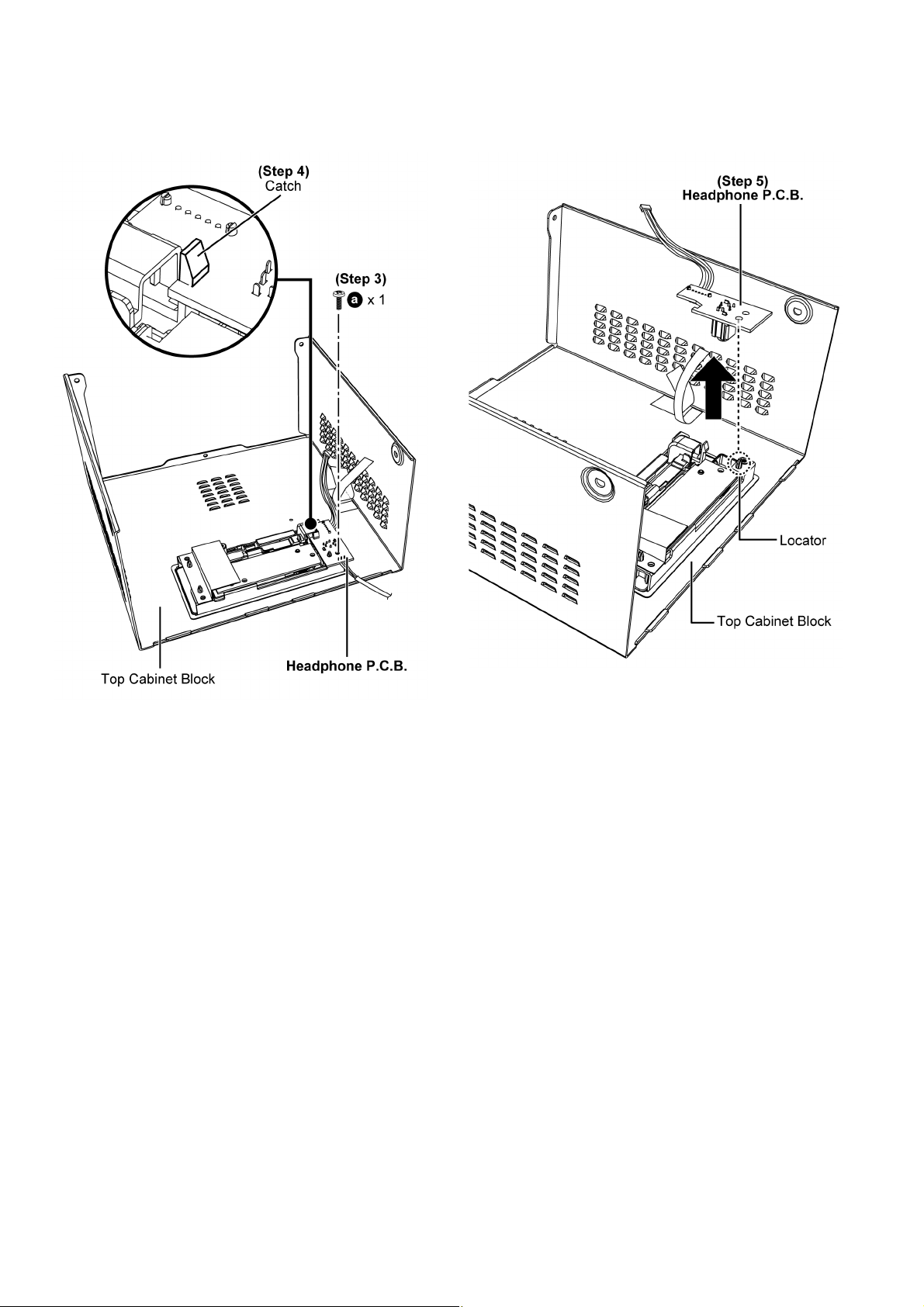
Step 3 : Remove 1 screw.
Step 4 : Release 1 catch.
Caution : During assembling, ensure the Head phone P.C.B.
is fully catched.
Step 5 : Remove the Headphone P.C.B..
Step 6 : Remove the Top Cabinet Block as shown.
Caution : During assembling, ensure the Headphone P.C.B.
is seated properly on the locator.
30
 Loading...