

Panasonic SAPMX-3-GN Service manual
I
T
I
y
A
A
A
y
T
T
CD Stereo System
SA-PMX3GN
Colour
(S)... Silver Type
ORDER NO. MD0806017CE
Notes: This model’s mechanism unit is DLS6C. Please refer to the original Service Manual (Order No.
MD0803034CE) for this mechanism.
Specifications
AMPLIFIER SECTION
RMS output power Stereo Mode
Front Ch (both ch driven) 80 W per channel (3 Ω), 1 kHz,
10% THD
otal RMS Stereo mode power 160 W
FM/AM TUNER, TERMINALS SECTION
Preset memory FM 30 stations
AM 15 stations
FrequencyModulation (FM)
Frequencyrange 87.50 to 108.00 MHz
(50 kHz step)
Sensitivit
S/N 50 dB 9.0 dBµV
ntenna terminals 75 Ω (unbalanced)
mplitude Modulation (AM)
Frequencyrange 522 to 1629 kHz (9 kHz step)
M Sensitivity S/N 20dB at 999
kHz
Music Port input jack
Sensitivit
erminal Stereo, 3.5 mm jack
Phone jack
erminal Stereo, 3.5 mm jack
Option port Version 1
4.5 dBµV (IHF)
660 µV/m
100 mV, 11 kΩ
I CD SECTION
Disc played (8 cm or 12 cm)
(1) CD, CD-R/RW (CD-DA, MP3 *)
* MPEG-1 Layer 3, MPEG-2 Layer 3
Pick up
Wavelength (CD) 785 nm
Laser power (CD) CLASS 1
Audio output (Disc)
Number of channels (FL, FR), 2 Channel
I USB SECTION
USB port
USB standard USB 2.0 full speed
Media file format support MP3 (*.mp3)
USB device file system FAT 12 / FAT 16 / FAT 32
USB port power Max 500 mA
USB ripping bit rate 128 / 192 / 320 kbps
Frequency response 4Hzto20kHz
Output level ( 1 kHz, 0 dB) 1000 mV ± 150 mV
S/N ratio >80dB
Dynamic range >80dB
Separation >60dB
Total harmonic distortion <0.1%
USB recording speed 1x, 4x (CD only)
© 2008 Matsushita Electric Industrial Co. Ltd.. All
rights reserved. Unauthorized copying and
distribution is a violation of law.
SA-PMX3GN
Recording file format MP3 (*.mp3)
I GENERAL
Power supply AC 230 to 240 V, 50 Hz
Power consumption 85 W
Dimensions (W x H x D) 175 mm x 240 mm x 349.8 mm
Mass 4.5 kg
Operating temperature range 0°C to +40°C
Operating humidity range 35 to 80% RH (no condensation)
Power consumption in standby
mode
Note:
1. Specifications are subject to change without notice.
Mass and dimensions are approximate.
2. Total harmonic distortion is measured by the digital spectrum
analyzer.
I System: SC-PMX3GN-S Music center: SA-PMX3GN-S
0.7 W (Approximate)
Speakers: SB-PMX3EG-K
CONTENTS
Page Page
1 Safety Precautions
2 Prevention of Electro Static Discharge (ESD) to
Electrostatically Sensitive (ES) Devices
3 Precaution of Laser Diode
4 Handling Precautions for Traverse Unit
5 Handling the Lead Free Solder
6 Operation Procedures
7 Self diagnosis and special mode setting
8 Assembling and Disassembling
9 Assembling and Disassembling of CD Mechanism Unit
10 Service Fixture and Tools
3
11 Service Position 43
12 Voltage Measurement & Waveform Chart
5
13 Wiring Connection Diagram
14 Block Diagram
6
7
15 Notes Of Schematic Diagram
9
16 Schematic Diagram
17 Printed Circuit Board
10
12
18 Illustration of IC’s, Transistors and Diodes
17
19 Terminal Function of IC’s
20 Exploded Views
39
42
21 Replacement Parts List
48
57
59
65
67
81
87
88
91
93
2
SA-PMX3GN
1 Safety Precautions
1.1. General Guidelines
1. When servicing, observe the original lead dress. If a short circuit is found, replace all parts which have been overheated or
damaged by the short circuit.
2. After servicing, ensure that all the protective devices such as insulation barriers, insulation papers shields are properly installed.
3. After servicing, check for leakage current checks to prevent from being expose d to shock hazards.
1.1.1. Leakage Current Cold Check
1. Unplug the AC cord and connect a jumper between the two prongs on the plug.
2. Using an ohmmeter measure the resistance value, between the jumpered AC plug and each exposed metallic cabinet part on
the equipment such as screwheads, connectors, control shafts, etc. When the exposed metallic part has a return path to the
chassis, the reading should be between 1MΩ and 5.2Ω.
When the exposed metal does not have a return path to the chassis, the reading must be
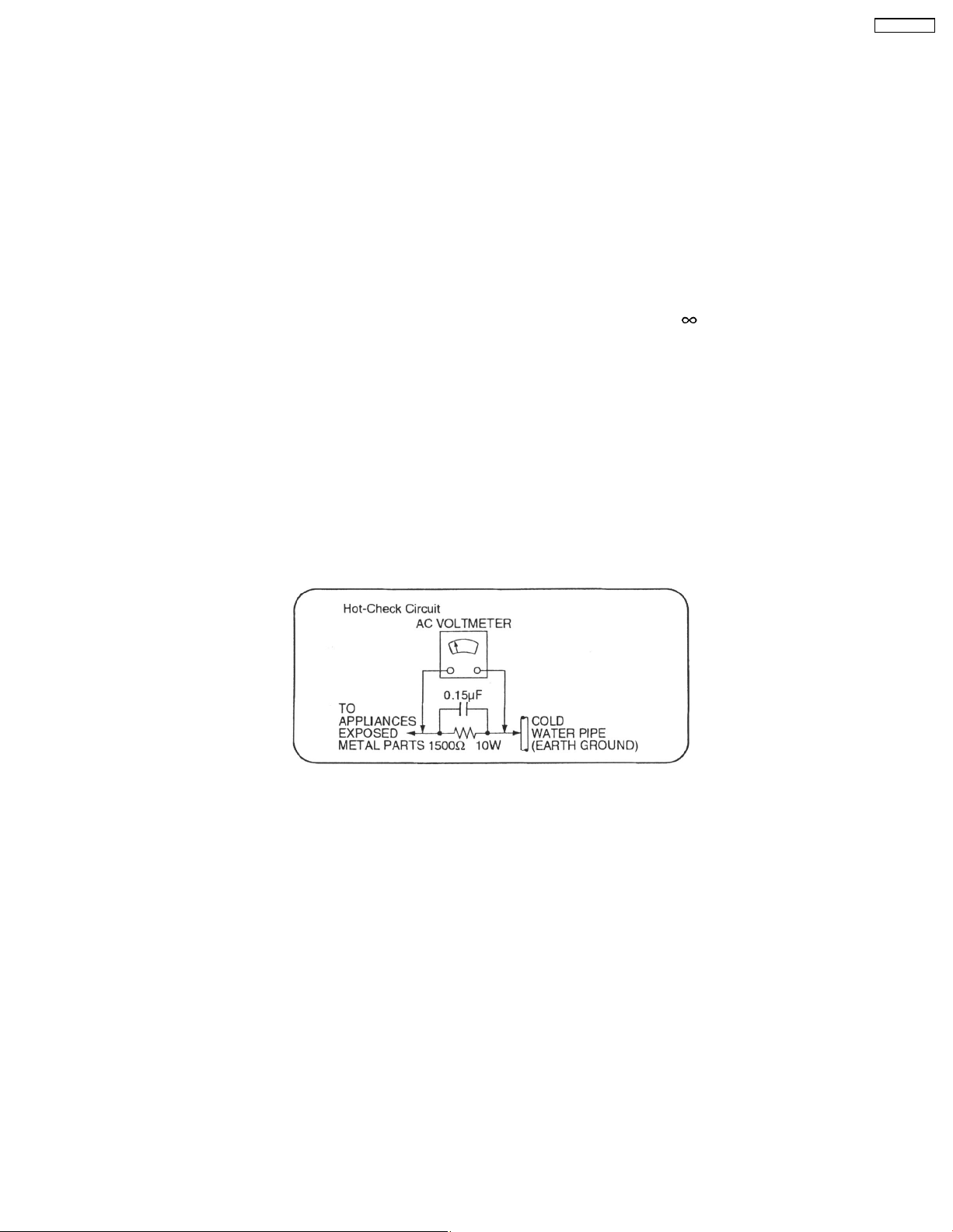
1.1.2. Leakage Current Hot Check
1. Plug the AC cord directly into the AC outlet. Do not use an isolation transformer for this check.
2. Connect a 1.5kΩ, 10 watts resistor, in parallel with a 0.15µF capacitors, between each exposed metallic part on the set and a
good earth ground such as a water pipe, as shown in Figure 1.
3. Use an AC voltmeter, with 1000 ohms/volt or more sensitivity, to measure the potential across the resistor.
4. Check each exposed metallic part, and measure the voltage at each point.
5. Reverse the AC plug in the AC outlet and repeat each of the above measurements.
6. The potential at any point should not exceed 0.75 volts RMS. A leakage current tester (Simpson Model 229 or equivalent) may
be used to make the hot checks, leakage current must not exceed 1/2 milliamp. should the measurement is outside of the limits
specified, there is a possibility of a shock hazard, and the equipment should be repaired and re-checked before it is returned
to the customer.
.
Figure 1
3
SA-PMX3GN
1.2. Before Repair and Adjustment
Disconnect AC power, discharge Power Supply Capacitors C2602, C2641, C2642, C5015, C5016, C5110, C5916, C5917 and
C5938 through a 10Ω, 1W resistor to ground.
DO NOT SHORT-CIRCUIT DIRECTLY (with a screwdriver blade, for instance), as this may destroy solid state devices.
After repairs are completed, restore power gradually using a variac, to avoid overcurrent.
• Current consumption at AC 230-240 V, at 50 Hz in NO SIGNAL mode (at volume min) should be ~300 mA.
1.3. Protection Circuitry
The protection circuitry may have operated if either of the following conditions are noticed:
• No sound is heard when the power is turned on.
• Sound stops during a performance.
The function of this circuitry is to prevent circuitry damage if, for example, the positive and negative speaker connection wires are
"shorted", or if speaker systems with an impedance less than the indicated rated impedance of the amplifier are used.
If this occurs, follow the procedure outlines below:
1. Turn off the power.
2. Determine the cause of the problem and correct it.
3. Turn on the power once again after one minute.
Note:
When the protection circuitry functions, the unit will not operate unless the power is first turned off and then on again.
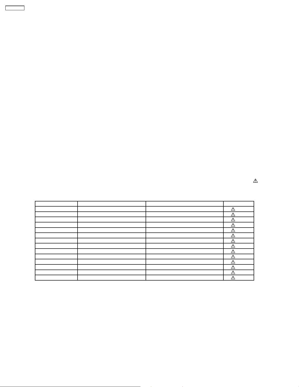
1.4. Safety Part Information
Safety Parts List:
There are special components used in this equipment which are important for safety.These parts are marked by
Schematic Diagrams & Replac ement Parts List. It is essential that these critical parts should be replaced with manufacturer’s
specified parts to prevent shock, fire or other hazards. Do not modify the original design without permission of manufacturer.
Table 1
Reference No. Part No. Part Name & Description Remarks
A2 K2CJ2DA00008 AC CORD [M]
JK5970 K2AA2B000017 AC INLET [M]
T5900 G4CYAYY00174 POWER TRANSFORMER [M]
T5901 G4CYAYY00137 SUB-TRANSFORMER [M]
F5970 K5D162BLA013 FUSE [M]
L5970 ELF15N035AN LINE FILTER [M]
RL5970 K6B1AEA00003 POWER RELAY [M]
Z5970 ERZVA5Z471 ZENER [M]
FP5920 K5G402AA0002 FUSE PROTECTOR [M]
FP5922 K5G202AA0002 FUSE PROTECTOR [M]
22 RFKHAPMX3GNS REAR CABINET ASS´Y [M]
21 RKMX0142-S TOP CABINET [M]
PCB1 REPX0633A TRANSFORMER P.C.B. [M] (RTL)
301 RAEX0190Z-V TRAVERSE UNIT [M] (RTL)
in the
4

SA-PMX3GN
2 Prevention of Electro Static Discharge (ESD) to
Electrostatically Sensitive (ES) Devices
Some semiconductor (solid state) devices can be damaged easily by electricity. Such components commonly are called
Electrostatically Sensitive (ES) Devices. Examples of typical ES devices are integrated circuits and some field-effect transistors and
semiconductor “chip” components. The following techniques should be used to help reduce the inciden ce of component damage
caused by electro static discharge (ESD).
1. Immediately before handlin g any semiconductor component or semiconductor-equiped assembly, drain off any ESD on your
body by touchin g a known earth ground. Alternatively, obtain and wear a commercially available discharging ESD wrist strap,
which should be removed for potential shock reasons prior to applyin g power to the unit under test.
2. After removing an electrical assembly equiped with ES devices, place the assembly on a conductive surface such as aluminium
foil, to prevent electrostatic charge build up or exposure of the assembly.
3. Use only a grounded-tip soldering iron to solder or unsolder ES devices.
4. Use only an anti-static solder remover device. Some solder removal devices not classified as “anti-static (ESD protected)” can
generate electrical charge to damage ES devices.
5. Do not use freon-propelled chemicals. These can generate electrical charges sufficient to damage ES devices.
6. Do not remove a replacement ES device from its protective package until immediately before you are ready to install it. (Most
replacement ES devices are packaged with leads electrically shorted together by conductive foam, aluminium foil or
comparable conductive material).
7. Immediately before removing the protective material from the leads of a replacement ES device, touch the protective material
to the chassis or circuit assembly into which the device will be installed.
Caution
Be sure no power is applied to the chassis or circuit, and observe all other safety precautions.
8. Minimize body motions when handling unpackaged replacement ES devices. (Otherwise harmless motion such as the brushing
together of your clothes fabric or the lifting of your foot from a carpeted floor can generate static electricity (ESD) sufficient to
damage an ES device).
5
SA-PMX3GN
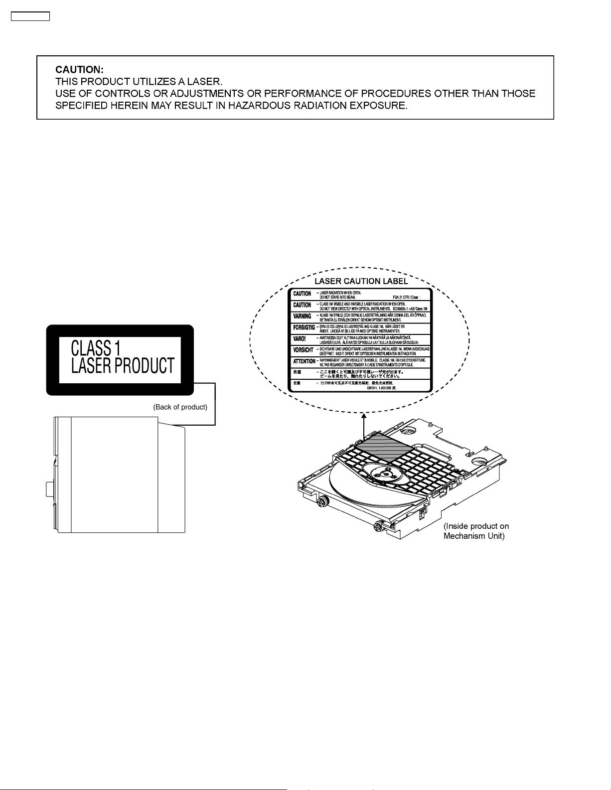
3 Precaution of Laser Diode
CAUTION :
This product utilizes a laser diode with the unit turned "on", invisible laser radiation is emitted from the pickup lens.
Wavelength: 785 nm (CD)
Maximum output radiation power from pickup: 100 µW/VDE
Laser radiation from the pickup unit is safety level, but be sure the followings:
1. Do not disassemble the pickup unit, since radiation from exposed laser diode is dangerous.
2. Do not adjust the variable resistor on the pickup unit. It was already adjusted.
3. Do not look at the focus lens using optical instruments.
4. Recommend not to look at pickup lens for a long time.
6
SA-PMX3GN
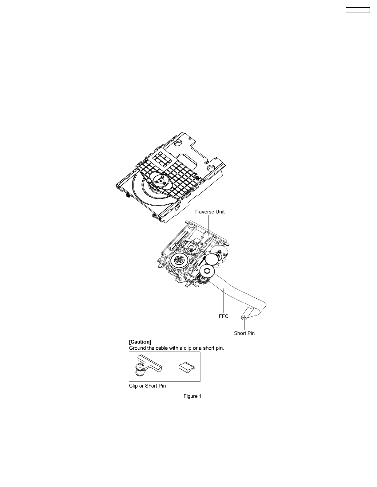
4 Handling Precautions for Traverse Unit
The laser diode in the optical pickup unit may break down due to static electricity of clothes or human body. Special care must be
taken avoid caution to electrostatic breakdown when servicing and handling the laser diode in the traverse unit.
4.1. Cautions to Be Taken in Handling the Optical Pickup Unit
The laser diode in the optical pickup unit may be damaged due to electrostatic discharge generating from clothes or human body.
Special care must be taken avoid caution to electrostatic discharge damage when servicing the laser diode.
1. Do not give a considerable shock to the optical pickup unit as it has an extremely high-precise structure.
2. To prevent the laser diode from the electrostatic discharge damage, the flexible cable of the optical pickup unit removed should
be short-circuited with a short pin or a clip.
3. The flexible cable may be cut off if an excessive force is applied to it. Use caution when handling the flexible cable.
4. The antistatic FPC is connected to the new optical pickup unit. After replacing the optical pickup unit and connecting the flexible
cable, cut off the antistatic FPC.
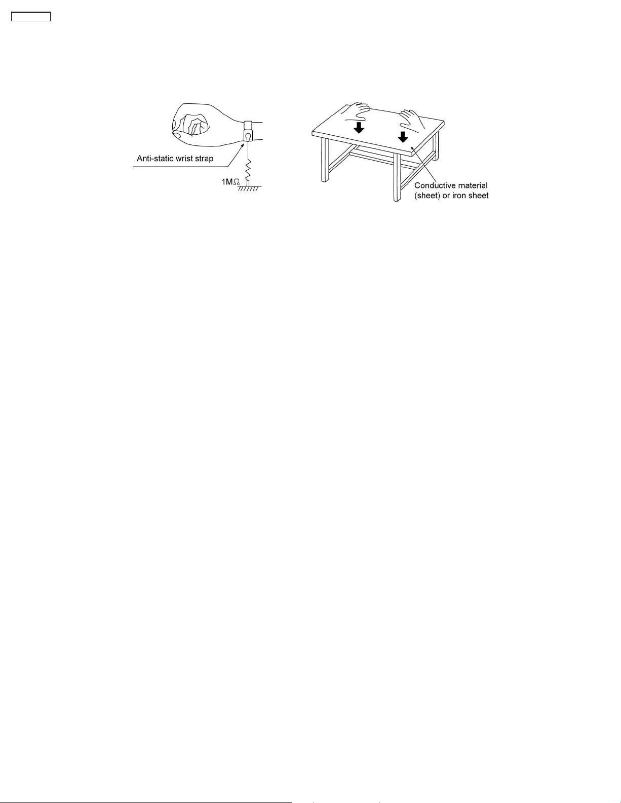
4.2. Grounding for electrostatic breakdown prevention
Some devices such as the DVD player use the optical pickup (laser diode) and the optical pickup will be damaged by static
electricity in the working environment. Proceed servicing works under the working environment where grounding works is
completed.
4.2.1. Worktable grounding
1. Put a conductive material (sheet) or iron sheet on the area where the optical pickup is placed, and ground the sheet.
7
SA-PMX3GN
4.2.2. Human body grounding
1. Use the anti-static wrist strap to discharge the static electricity form your body.
8
SA-PMX3GN
5 Handling the Lead Free Solder
5.1. General description about Lead Free Solder (PbF)
The lead free solder has been used in the mounting process of all electrical components on the printed circuit boards used for this
equipment in considering the globally environmental conservation.
The normal solder is the alloy of tin (Sn) and lead (Pb). On the other hand, the lead free solder is the alloy mainly consists of tin
(Sn), silver (Ag) and Copper (Cu), and the melting point of the lead free solder is higher approx.30 degrees C (86°F) more than that
of the normal solder.
Definition of PCB Lead Free Solder being used
The letter of “PbF” is printed either foil side or components side on the PCB using the lead free solder.
(See right figure)
Service caution for repair work using Lead Free Solder (PbF)
• The lead free solder has to be used when repairing the equipment for which the lead free solder is used.
(Definition: The letter of “PbF” is printed on the PCB using the lead free solder.)
• To put lead free solder, it should be well molten and mixed with the original lead free solder.
• Remove the remaining lead free solder on the PCB cleanly for soldering of the new IC.
• Since the melting point of the lead free solder is higher than that of the normal lead solder, it takes the longer time to melt
the lead free solder.
• Use the soldering iron (more than 70W) equipped with the temperature control after setting the temperature at 350±30
degrees C (662±86°F).
Recommended Lead Free Solder (Service Parts Route.)
• The following 3 types of lead free solder are available through the service parts route.
RFKZ03D01K-----------(0.3mm 100g Reel)
RFKZ06D01K-----------(0.6mm 100g Reel)
RFKZ10D01K-----------(1.0mm 100g Reel)
Note
* Ingredient: Tin (Sn), 96.5%, Silver (Ag) 3.0%, Copper (Cu) 0.5%, Cobalt (Co) / Germanium (Ge) 0.1 to 0.3%
9
SA-PMX3GN
6 Operation Procedures
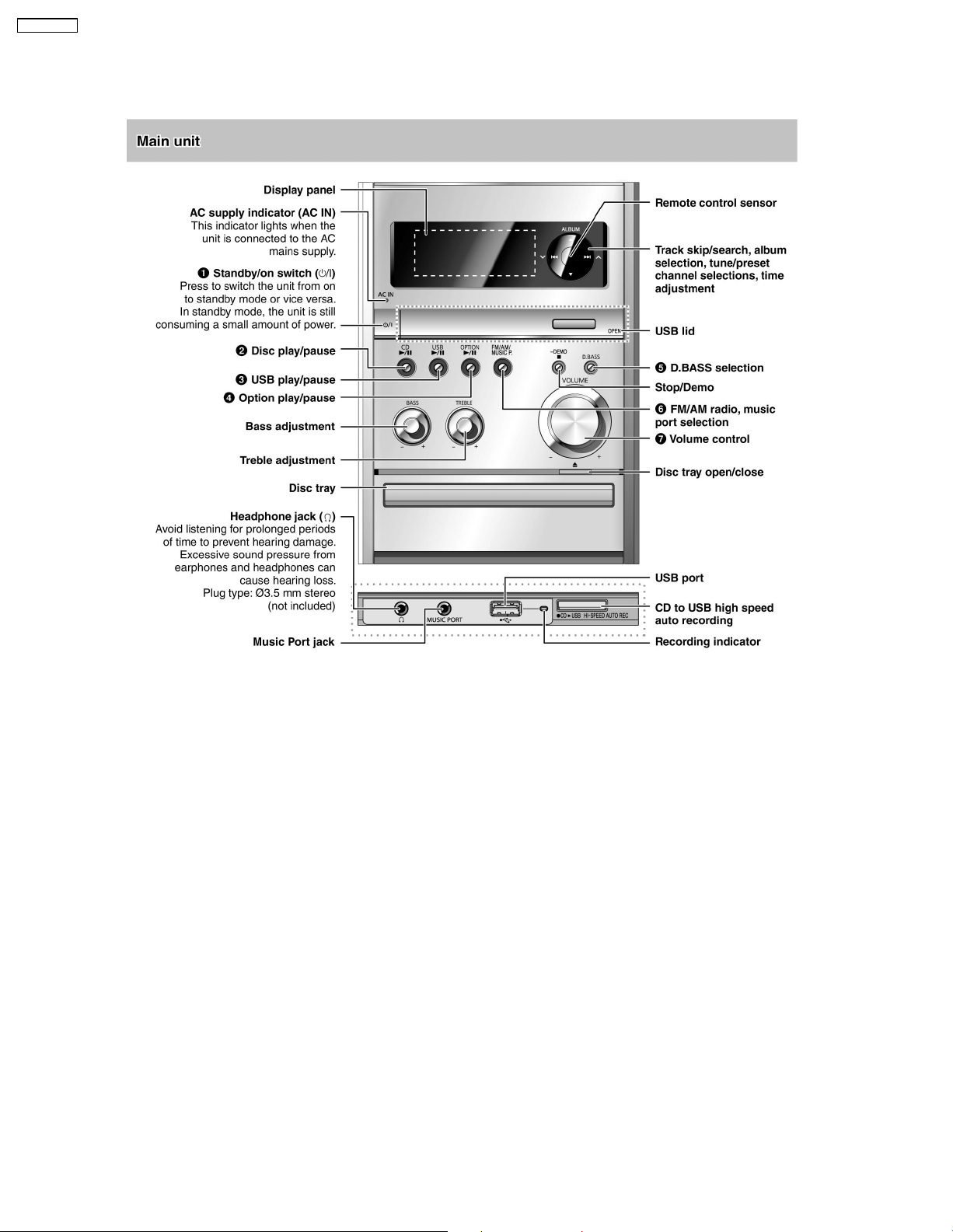
6.1. Main Unit Key Buttons Operation
10
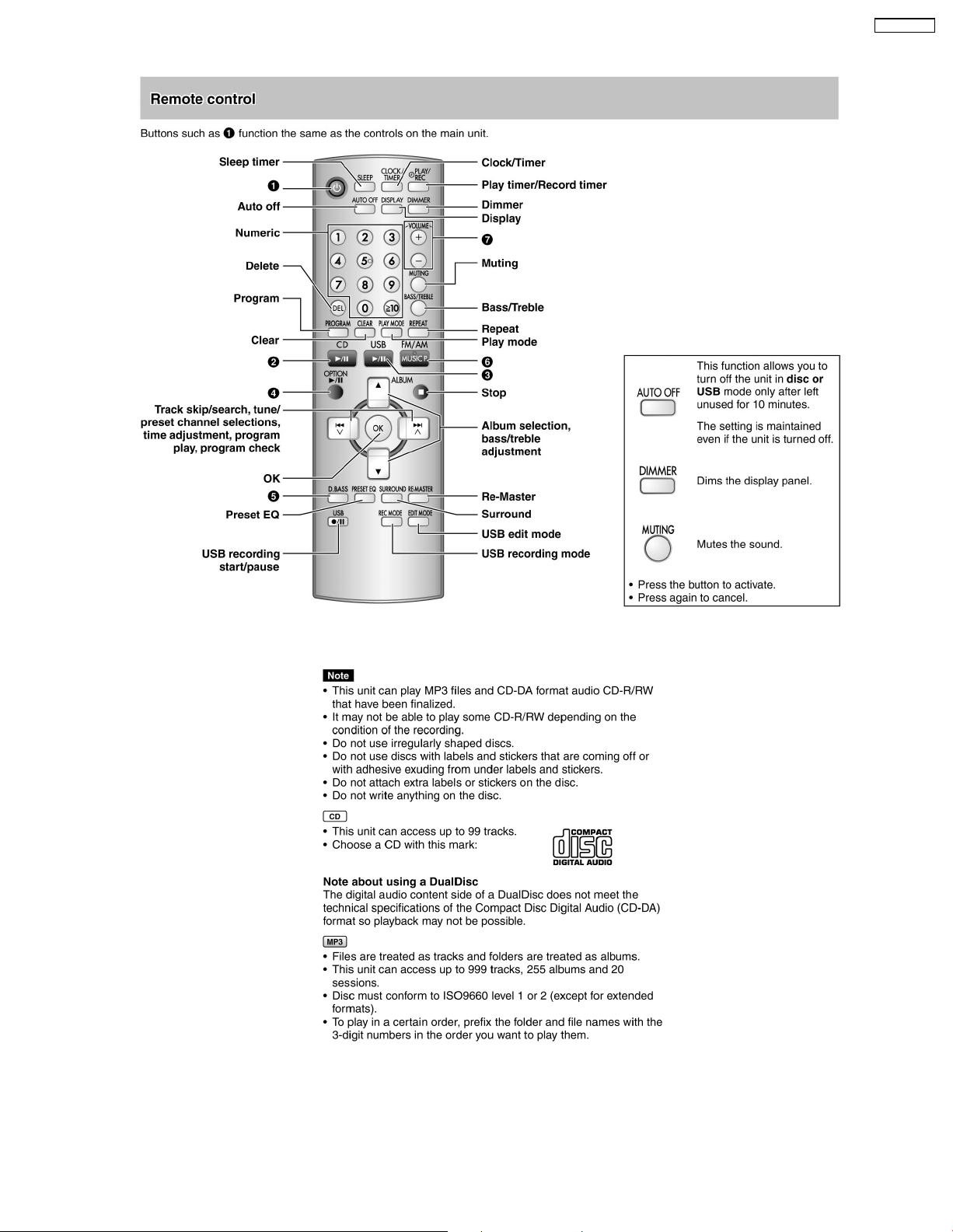
6.2. Remote Control Key Buttons Operation
SA-PMX3GN
6.3. Disc Information
11
SA-PMX3GN
7 Self diagnosis and special mode setting
This unit is equipped with features of self-diagnostic & special mode setting for checking the functions & reliability.
Special Note : Checking of the reliability (ageing) & changer operation must be carry out to ensure good working condition
in unit.
7.1. Service Mode Summary Table
The service modes can be activated by pressing various button combination on the main unit and remote control unit.Below is the
summary for the various modes for checking:
Player buttons Remote control unit buttons Application Note
[STOP] [4], [7] Entering into doctor mode (Refer to section .7.2.1. service mode
[STOP] [ ] Entering into service mode (Refer to section .7.2.1. service mode
Mode Remote control unit buttons Application Note
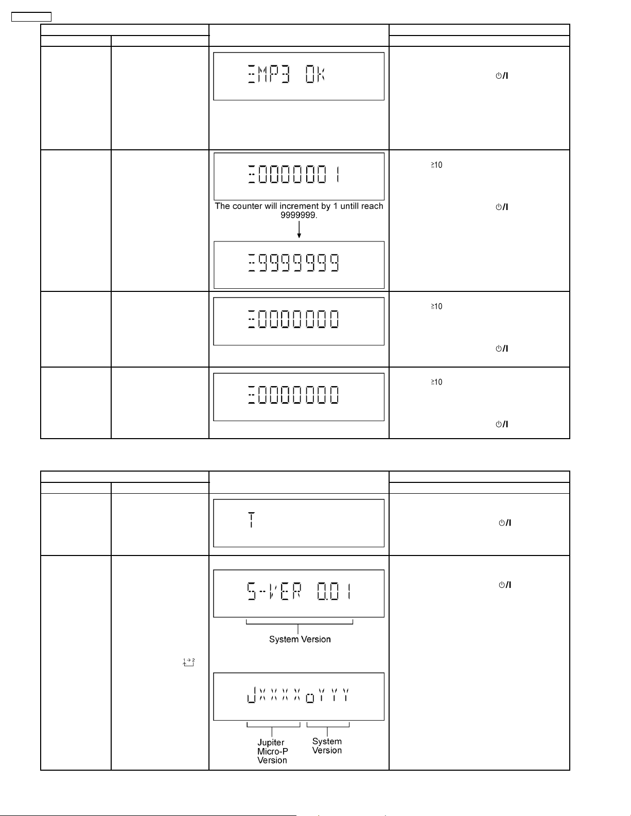
In Doctor Mode [1] FL all segment & LED inspection (Refer to section .7.2.2. service mode
[MUSIC.P] Tuner Check (Refer to section .7.2.2. service mode
[7] Volume 50 setting check (Refer to section .7.2.2. service mode
[8] Volume 29 setting check (Refer to section .7.2.2. service mode
[9] Volume 0 setting check (Refer to section .7.2.2. service mode
[2] Micro-P Version Display (Refer to section .7.2.2. service mode
[4] CD→USB Recording & Playing inspection (Refer to section .7.2.2. service mode
[5] CD-MP3 Reading & Playing inspection (Refer to section .7.2.2. service mode
[ ], [1], [1] CD Loading Test Mode (Refer to section .7.2.2. service mode
[ ], [1], [2] CD Traverse Unit Test Mode (Refer to section .7.2.2. service mode
[ ], [1], [3] CD Combination Test Mode (Refer to section .7.2.2. service mode
Table 1 for more information.)
Table 1 for more information.)
Table 2 for more information.)
Table 2 for more information.)
Table 2 for more information.)
Table 2 for more information.)
Table 2 for more information.)
Table 2 for more information.)
Table 2 for more information.)
Table 2 for more information.)
Table 2 for more information.)
Table 2 for more information.)
Table 2 for more information.)
Mode Remote control unit buttons Application Note
In Service Mode [1] self diagnostic history (Refer to section .7.2.3. service mode
[2] Micro-P FW (Refer to section .7.2.3. service mode
[3] Cold Start (Reset) (Refer to section .7.2.3. service mode
Table 3 for more information.)
Table 3 for more information.)
Table 3 for more information.)
7.2. Service Mode Table
Below is the various special modes for checking:-
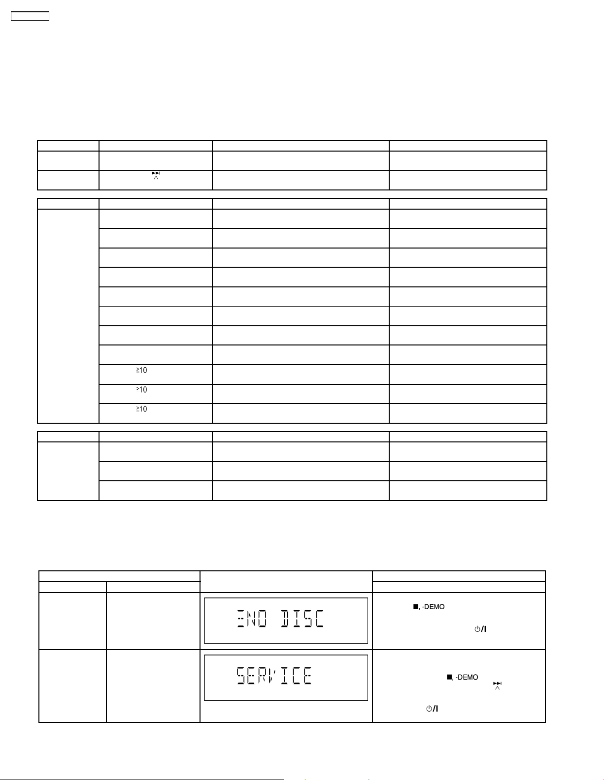
7.2.1. Service Mode Table 1
Item FL Display Key Operation
Mode Name Description Front Key
Doctor Mode To enter into Doctor
Mode.
Service Mode To enter into Service
Mode.
In any mode:
1. Press [
by [4] and [7] on remote control.
To exit Doctor Mode, press [
main unit or remote control.
1. Select [CD] for DISC mode (Ensure no disc
is inserted).
2. Press and hold [
unit for 2 seconds follow by [
remote control.
To exit, press [
remote control.
] button on main unit follow
] button on
]button on main
]on
] button on main unit or
12
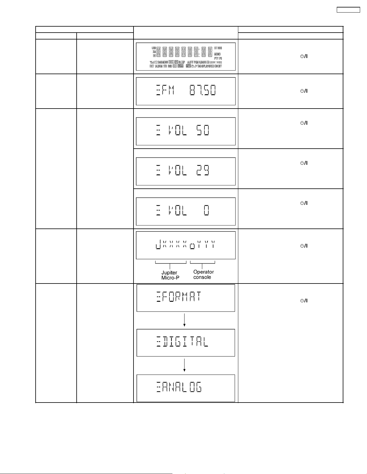
7.2.2. Service Mode Table 2
Item FL Display Key Operation
Mode Name Description Front Key
FL Display Test To check the FL
segments display (All
segments will light up)
In doctor mode:
1. Press [1] button on remote control.
To exit Doctor Mode, press [
main unit or remote control.
SA-PMX3GN
] button on
Tuner Check To Inspect Tuner Check In doctor mode:
Volume Setting
Mode
Micro-P Version
Display
To check for the volume
setting of the main unit.
The volume will be
automatically set to its
respective level (in dB).
During this mode,
treble/bass/EQ will be set
to ‘0’dB & OFF.
Checking of various
items and firmware
version.
Note: The microprocessor version as
shown is an example. It
will be revise when there
is an updates.
Display 1 In doctor mode:
Display 1 In doctor mode:
Display 1 In doctor mode:
1. Press [MUSIC.P] button on remote control.
To exit Doctor Mode, press [
main unit or remote control.
1. Press [7] button on remote control.
To exit Doctor Mode, press [
main unit or remote control.
2. Press [8] button on remote control.
To exit Doctor Mode, press [
main unit or remote control.
3. Press [9] button on remote control.
To exit Doctor Mode, press [
main unit or remote control.
In doctor mode:
1. Press [2] button on remote control.
To exit Doctor Mode, press [
main unit or remote control.
] button on
] button on
] button on
] button on
] button on
CD→USB
Recording &
Playing inspection
To check for the
CD→USB Recording
setting of the main unit.
The volume will be
automatically set to its
respective level (in dB).
During this mode,
treble/bass/EQ will be set
to ‘0’dB & OFF.
In doctor mode:
1. Press [4] button on remote control.
To exit Doctor Mode, press [
main unit or remote control.
] button on
13
SA-PMX3GN
Item FL Display Key Operation
Mode Name Description Front Key
CD-MP3 Reading
& Playing
inspection
CD Loading Test
Mode
To check for the CD-MP3
Reading setting of the
main unit. The volume
will be automatically set
to its respective level (in
dB). During this mode,
treble/bass/EQ will be set
to ‘0’dB & OFF.
(For more information,
refer to section 8.2.4)
To determine the
reliability of CD Loading
Unit.
To check for the
open/close operation for
the CD loading unit. It
fails when there is
abnormality in opening or
closing.
In doctor mode:
1. Press [5] button on remote control.
To exit Doctor Mode, press [
main unit or remote control.
In doctor Mode:
1. Press [
To cancel, press [PROGRAM] button on remote
control.
To exit Doctor Mode, press [
main unit or remote control.
] button on
], [1] & [1] button on remote
control.
] button on
CD Traverse Unit
Test Mode
CD Combination
Test Mode
To check for the traverse
unit operation. In this
mode, the first & lost
track is access & read
(TOC). It fails when TOC
is not completed by IDS
or the traverse is out of
focus.
A combination of CD
loading & Traverse unit
test.
In doctor Mode:
1. Press [
To cancel, press [PROGRAM] button on remote
control.
To exit Doctor Mode, press [
main unit or remote control.
In doctor Mode:
1. Press [
To cancel, press [PROGRAM] button on remote
control.
To exit Doctor Mode, press [
main unit or remote control.
7.2.3. Service Mode Table 3
Item FL Display Key Operation
Mode Name Description Front Key
Self Diagnostic
History
Micro-P Version
Display
Checking the records for
self-diagnostic.
Checking of various
items and firmware
version.
Note: The microprocessor version as
shown is an example. It
will be revise when there
is an updates.
(Display 1)
In service mode:
1. Press [1] button on remote control.
To exit Service Mode, press [
main unit or remote control.
To clear history, press & hold [0] for 5 seconds
or more.
In service mode:
1. Press [2] button on remote control.
To exit Service Mode, press [
main unit or remote control.
control.
], [1] & [2] button on remote
] button on
], [1] & [3] button on remote
control.
] button on
] button on
] button on
FL Display
sequenceDisplay [
]
(Display 2)
14
Item FL Display Key Operation
Mode Name Description Front Key
Cold Start (Reset) To activate cold start
ipon next AC power up.
In service mode:
1. Press [3] button on remote control.
To exit Service Mode, press [
main unit or remote control.
] button on
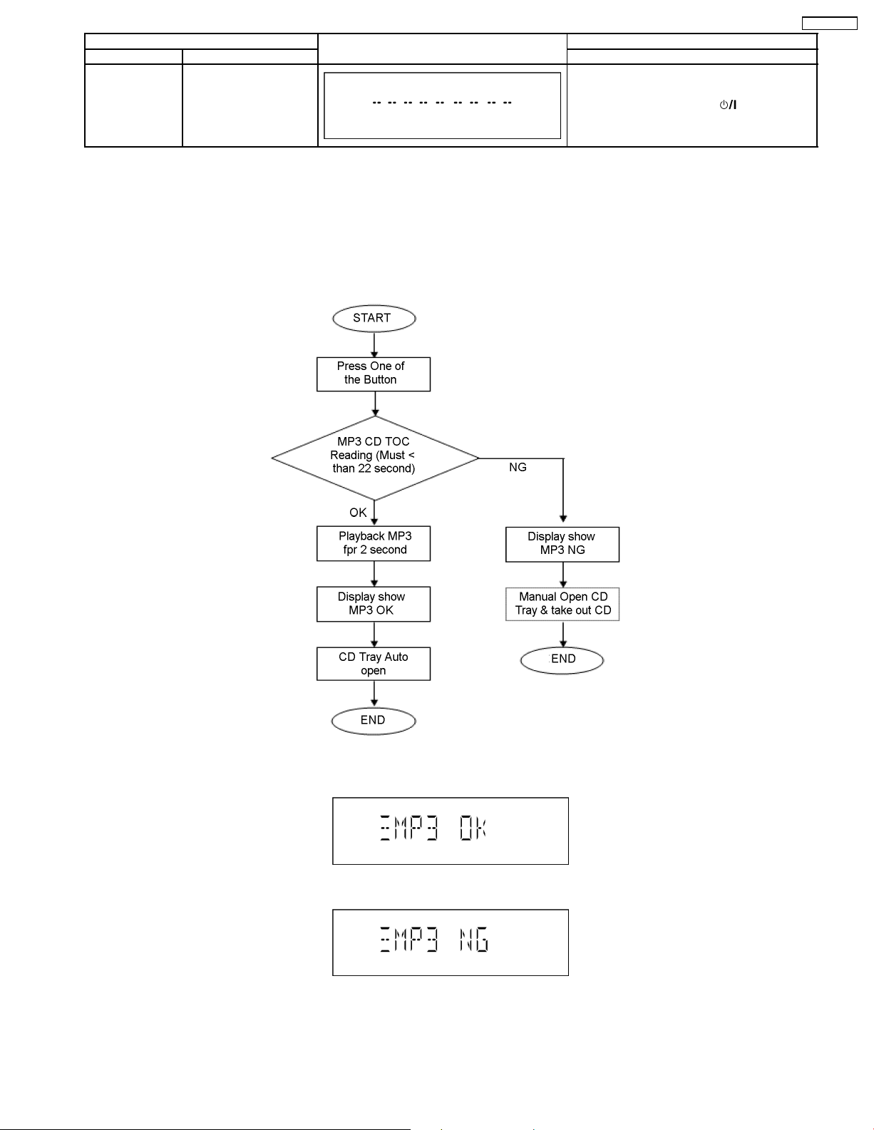
7.2.4. CD-MP3 Reading & Playing inspection
Purpose : CD-MP3 Readin g & Playing test.
Below is the procedures for this mode.
Step 1 : Enter into Doctor mode. (For more information refer to section 7.1 on key operation to enter into this mode)
Step 2 : Insert CD with MP3 tracks. (Ensure correct MP3 tracks is loaded)
Step 3 : Press [5] button on remote control. Execute MP3 Disc Check (Refer Flowchart below)
SA-PMX3GN
Result display :
• Displayed if MP3 test OK
• Displayed if MP3 test NG
15
SA-PMX3GN
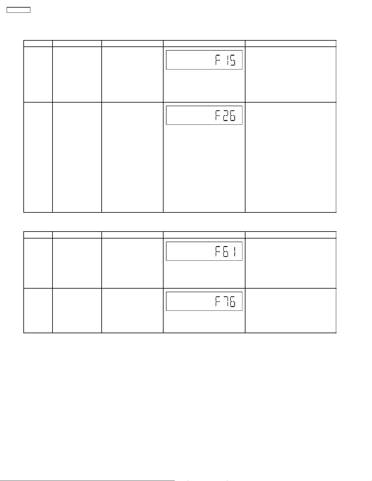
7.3. Error Code Table
7.3.1. Traverse Error Code Table
Error Code Diagnosis Contents Description of error Automatic FL Display Remarks
F15 CD REST SW
Abnormal
CD F26 Communication
between CD servo
LSI and micro-p
abnormal.
At initial setting of CD
traverse position, if the
RESET SW ON is not
detected even though the
fail safe timer time is over
(10 sec), it is memorized
as an error and the error
number can be cleared
only at the start up of
micro-p after reset.
1) At the time of switching
to CD function, SENSE =
H shall be detected using
DTMS system setting
command. If the error is
memorized when SENSE =
L is not detected within fail
safe timer time (20 mSec),
[F26] shall be displayed
simultaneously. This
display shall be retained if
the power is ON and at CD
function. If this error
occurs, CD operation
afterward shall not be
executed as in the case of
[NO DISC].
2) This error number can
be cleared only at the start
up of micro-p reset.
Press [1] on remote control for next error.
Press [1] on remote control for next
error.
7.3.2. Power Supply & Digital Amplifier Error Code Table
Error Code Diagnosis Contents Description of error Automatic FL Display Remarks
F61 The abnormalities in
an output or power
supply circuit of
POWER AMP
F76 Abnormality in the
output voltage of
stabilized power
supply.
In normal operation, when
DCDET2 goes to “L” (Low)
(Not during POWER OFF
condition), F61 appears on
FL Display for 1 second and
PCONT goes to “L” (Low).
This is due to speaker
output has DC voltage or
fan is not working.
In normal operation when
DCDET1 is detected “L”
(Low) for two consecutive
times, F76 is displayed on
FL for 1 second and after
that PCONT will be turned
to “L” (Low). This is due to
any of the DC voltages.
Press [1] on remote control for next
error.
Press [1] on main unit for next error.
16
SA-PMX3GN
8 Assembling and Disassembling
“ATTENTION SERVICER”
Be careful when disassembling and servicing.
Some chassis components may have sharp edges.
Special Note:
1. This model uses a CD mechanism unit (DLS6C). In this following section does not contain the necessary assembly and
disassembly information except the assembly and disassembly of the traverse unit. Kindly refer to the original service
manual for the CD mechanism unit. (Order No. MD0803034CE).
2. This section describes the disassembly procedures for all the major printed circuit boards and main components.
3. Before the disassembly process was carried out, do take special note that all safety precautions are to be carried out.
(Ensure that no AC power supply is connected during disassembling.)
4. For assembly after operation checks or replacement, reverse the respec tive procedures.
Special reassembly procedures are described only when required.
5. Do take note of the locators on each printed circuit board during reassembling procedures.
6. The Switch Regulator IC may have high temperature after prolonged use.
7. Use caution when removing the top cabinet and avoid touching heat sinks located in the unit.
8. Select items from the following index when checks or replacement are required.
• Disassembly of Top Panel
• Disassembly of Front Panel
• Disassembly of Jupiter P.C.B.
• Disassembly of Panel A P.C.B.
• Disassembly of Panel B P.C.B.
• Disassembly of Jupiter USB P.C.B.
• Disassembly of Rear Panel
• Disassembly of D-Port P.C.B.
• Disassembly of Main P.C.B.
• Disassembly of Transformer P.C.B.
• Replacement of Transistor (Q5927)
• Replacement of Transistor (Q5921)
• Disassembly of Power P.C.B.
• Replacement of Digital Power-Amp IC (IC5000)
• Replacement of Transistor (Q5105)
• Replacement of Transistor (Q5103)
• Replacement of Transistor (Q5100)
• Disassembly of Inner Chassis
• Disassembly of Mechanism Unit
• Disassembly of CD Servo P.C.B.
• Disassembly of USB Lid
• Disassembly of CD Lid
17

SA-PMX3GN
18
SA-PMX3GN
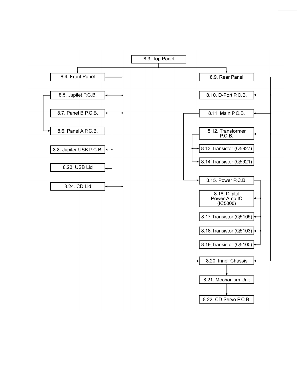
8.1. Disassembly flow chart
The following chart is the procedure for disassembling the casing and inside parts for internal inspection when carrying out the
servicing.
To assemble the unit, reverse the steps shown in the chart below.
19
SA-PMX3GN
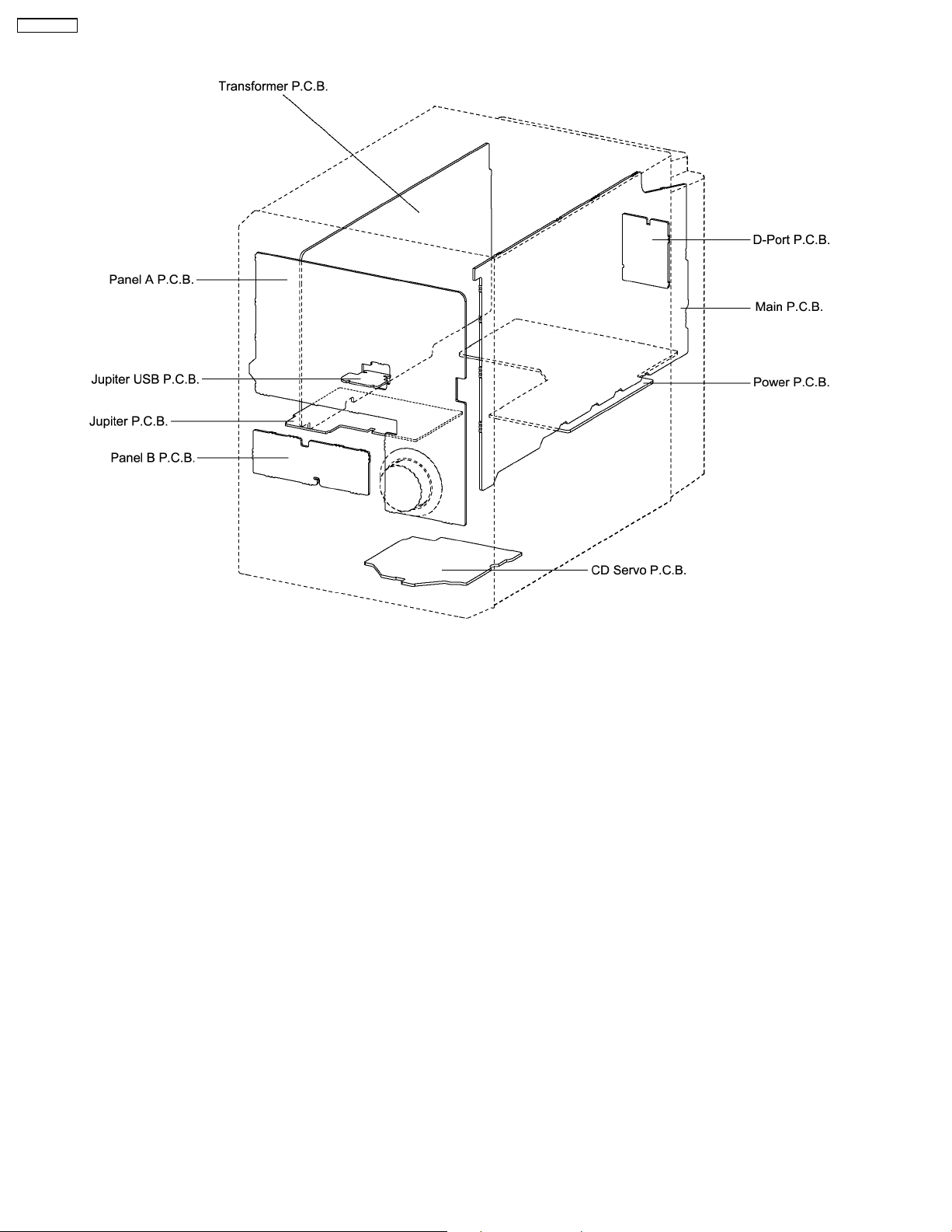
8.2. Main Parts Location Diagram
20
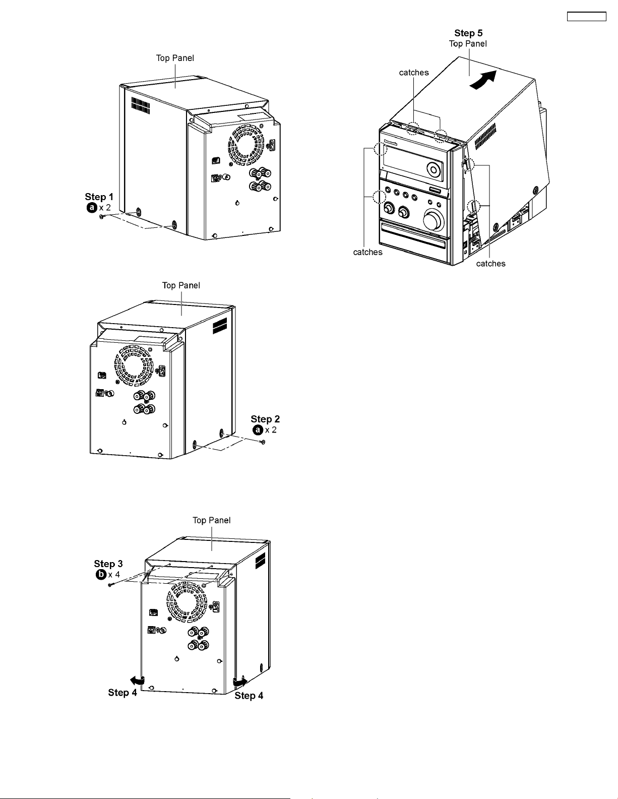
8.3. Disassembly of Top Panel
Step 1 : Remove 2 screws at the side of Top Panel (L).
SA-PMX3GN
Step 5 : Lift up the back part of the Top Panel and remove it in
the direction of arrow.
Note : During assembling of top panel, ensure it seats
properly.
Step 2 : Remove 2 screws at the side of Top Panel (R).
Step 3 : Remove 4 screws at the rear of Top Panel.
Step 4 : Lift both sides of Top Panel outwards in the direction
of arrow.
21
SA-PMX3GN
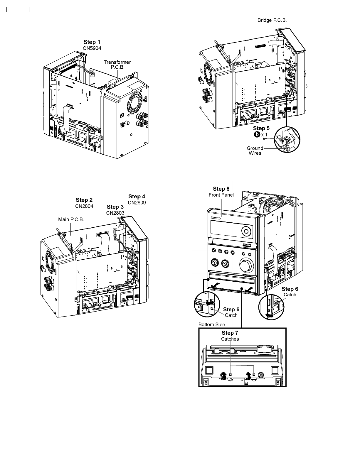
8.4. Disassembly of Front Panel
• Follow the (Step 1) - (Step 5) of Item 8.3
Step 1 : Detach 4P cable at the connector (CN5904) on
Transformer P.C.B..
Step 2 : Detach 20P FFC cable at the connector (CN2804) on
Main P.C.B..
Step 3 : Detach 17P FFC cable at the connector (CN2803) on
Main P.C.B..
Step 4 : Detach 4P cable at the connector (CN2809) on Main
P.C.B..
Step 5 : Remove 1 screw on Bridge P.C.B..
Caution : Do not exert strong force when releasing the
catches.
Step 6 : Release the catch at each side of the Front Panel in
the direction of arrow.
Step 7 : Release the catches at the bottom of the Front Panel.
Step 8 : Remove Front Panel.
22
8.5. Disassembly of Jupiter P.C.B.
• Follow the (Step 1) - (Step 5) of Item 8.3
• Follow the (Step 1) - (Step 8) of Item 8.4
SA-PMX3GN
Step 7 : Desolder 4 points.
Step 8 : Remove Jupiter P.C.B..
Note : During reassembling procedures, ensure 4 points is
solder onto Jupiter P.C.B..
8.6. Disassembly of Panel A P.C.B.
• Follow the (Step 1) - (Step 5) of Item 8.3
• Follow the (Step 1) - (Step 8) of Item 8.4
• Follow the (Step 1) - (Step 4) of Item 8.5
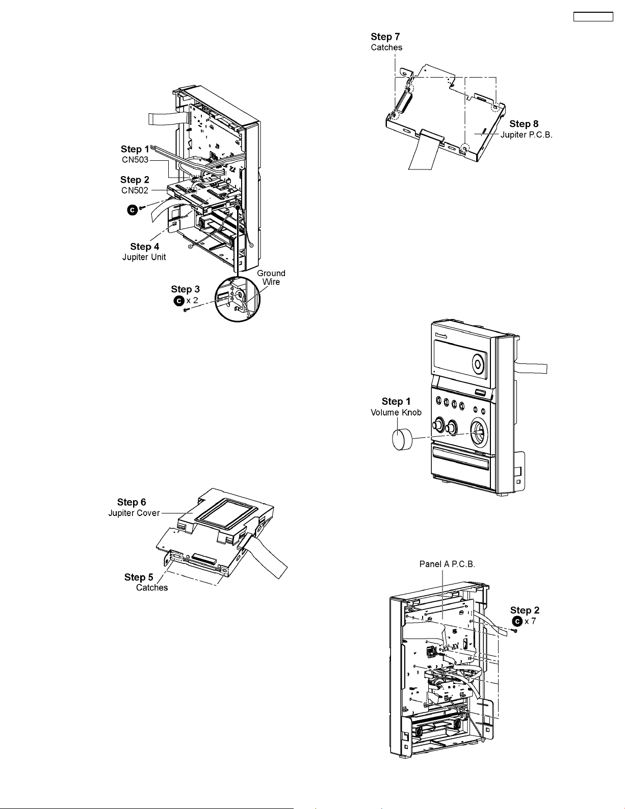
Step 1 : Detach 5P cable at the connector (CN503) on Jupiter
P.C.B..
Step 2 : Detach 6P FFC cable at the connector (CN502) on
Jupiter P.C.B..
Step 3 : Remove 2 screws.
Caution : Keep the Ground wire in safe place. Place it back
during assembling.
Step 4 : Remove the Jupiter Unit.
• Disassembly of Jupiter P.C.B. (Jupiter Unit)
Step 5 : Release all the catches.
Step 6 : Remove Jupiter Cover.
Step 1 : Remove the Volume Knob.
23
SA-PMX3GN
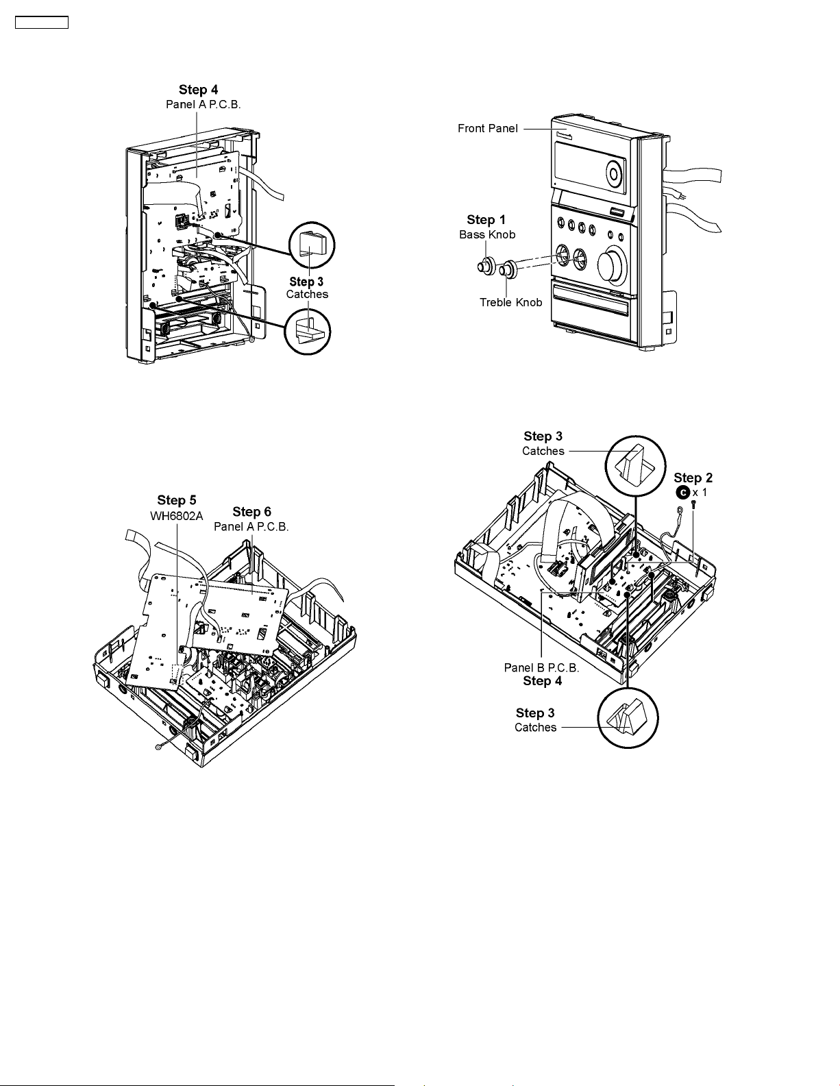
Step 2 : Remove 7 screws on the Panel A P.C.B..
8.7. Disassembly of Panel B P.C.B.
• Follow the (Step 1) - (Step 5) of Item 8.3
• Follow the (Step 1) - (Step 8) of Item 8.4
Step 3 : Release all the catches.
Step 4 : Release Panel A P.C.B..
Note: During reassembling procedures, ensure Panel A
P.C.B. is fully catched onto Front Panel.
Step 5 : Desolder 6P cable (WH6802) at Panel A P.C.B..
Step 6 : Remove Panel A P.C.B..
Note: During reassembling procedures, ensure 6P cable
(WH6802) are soldered on Panel A P.C.B..
Step 1 : Remove the Bass Knob and Treble Knob.
Step 2 : Remove 1 screw from Panel B P.C.B..
Step 3 : Release all the catches.
Step 4 : Release Panel B P.C.B..
Note: During reassembling procedures, ensure Panel B
P.C.B. is fully catched onto Front Panel.
24
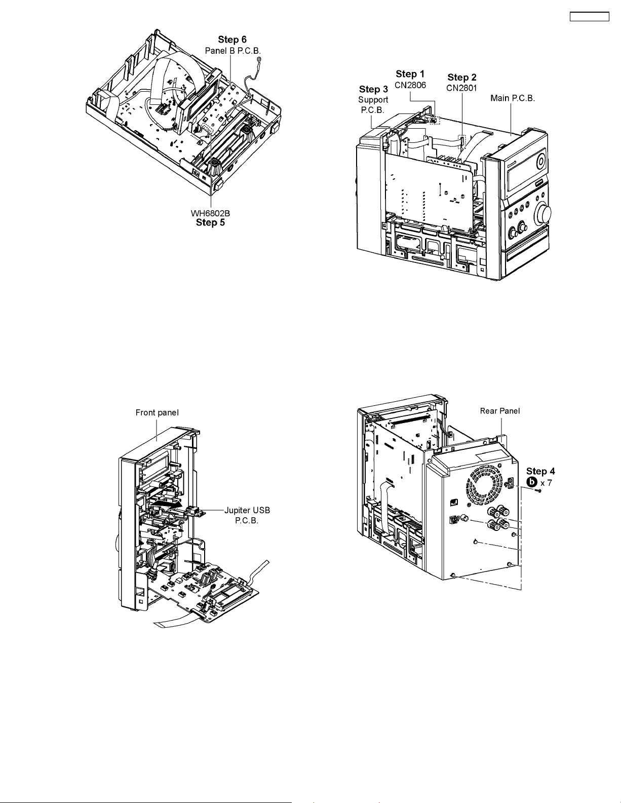
Step 5 : Desolder 6P cable (WH6881) at Panel B P.C.B..
Step 6 : Remove Panel B P.C.B..
Note: During reassembling procedures, ensure 6P cable
(WH6881) are soldered on Panel B P.C.B..
SA-PMX3GN
8.9. Disassembly of Rear Panel
• Follow the (Step 1) - (Step 5) of Item 8.3
8.8. Disassembly of Jupiter USB
P.C.B.
• Follow the (Step 1) - (Step 5) of Item 8.3
• Follow the (Step 1) - (Step 8) of Item 8.4
• Follow the (Step 1) - (Step 4) of Item 8.5
• Follow the (Step 1) - (Step 4) of Item 8.6
Step 1 : Detach 2P cable at the connector (CN2806) on Main
P.C.B..
Step 2 : Detach 14P FFC cable at the connector (CN2801) on
Main P.C.B..
Step 3 : Remove cable from Support P.C.B..
Step 1 : Remove Jupiter USB P.C.B. from Front Panel in the
direction of arrow.
Step 4 : Remove 7 screws from the Rear Panel.
25
SA-PMX3GN
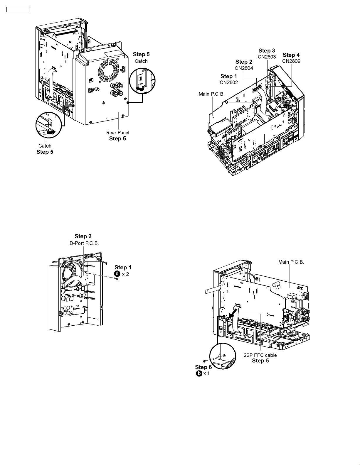
Step 5 : Releas e the catch at each side of the Rear Panel in
the direction of arrow.
Step 6 : Remove Rear Panel.
8.10. Disassembly of D-Port P.C.B.
• Follow the (Step 1) - (Step 5) of Item 8.3
• Follow the (Step 1) - (Step 6) of Item 8.9
8.11. Disassembly of Main P.C.B.
• Follow the (Step 1) - (Step 5) of Item 8.3
• Follow the (Step 1) - (Step 6) of Item 8.9
Step 1 : Detach 22P FFC cable at the connector (CN2802) on
Main P.C.B..
Step 2 : Detach 20P FFC cable at the connector (CN2804) on
Main P.C.B..
Step 3 : Detach 17P FFC cable at the connector (CN2803) on
Main P.C.B..
Step 4 : Detach 4P cable at the connector (CN2809) on Main
P.C.B..
Step 1 : Remove 2 screws from D-Port P.C.B..
Step 2 : Remove D-Port P.C.B..
Step 5 : Remove 22P FFC cable from Main P.C.B. in the
direction of arrow.
Step 6 : Remove 1 screw from Main P.C.B..
26
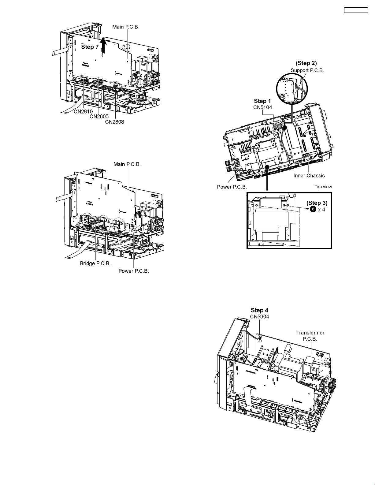
Step 7 : Lift up to remove Main P.C.B..
SA-PMX3GN
8.12. Disassembly of Transformer
P.C.B.
• Follow the (Step 1) - (Step 5) of Item 8.3
• Follow the (Step 1) - (Step 6) of Item 8.9
Note: During reassembling procedures, ensure that Main
P.C.B. is properly connected to Bridge P.C.B. and Power
P.C.B..
Step 1 : Detach 8P cable at the connector (CN5104) on Power
P.C.B..
Step 2 : Remove 8P cable from Support P.C.B..
Step 3 : Remove 4 screws at Inner Chassis.
Step 4 : Detach 4P cable (CN5904) at the connector on
Transformer P.C.B..
27
SA-PMX3GN
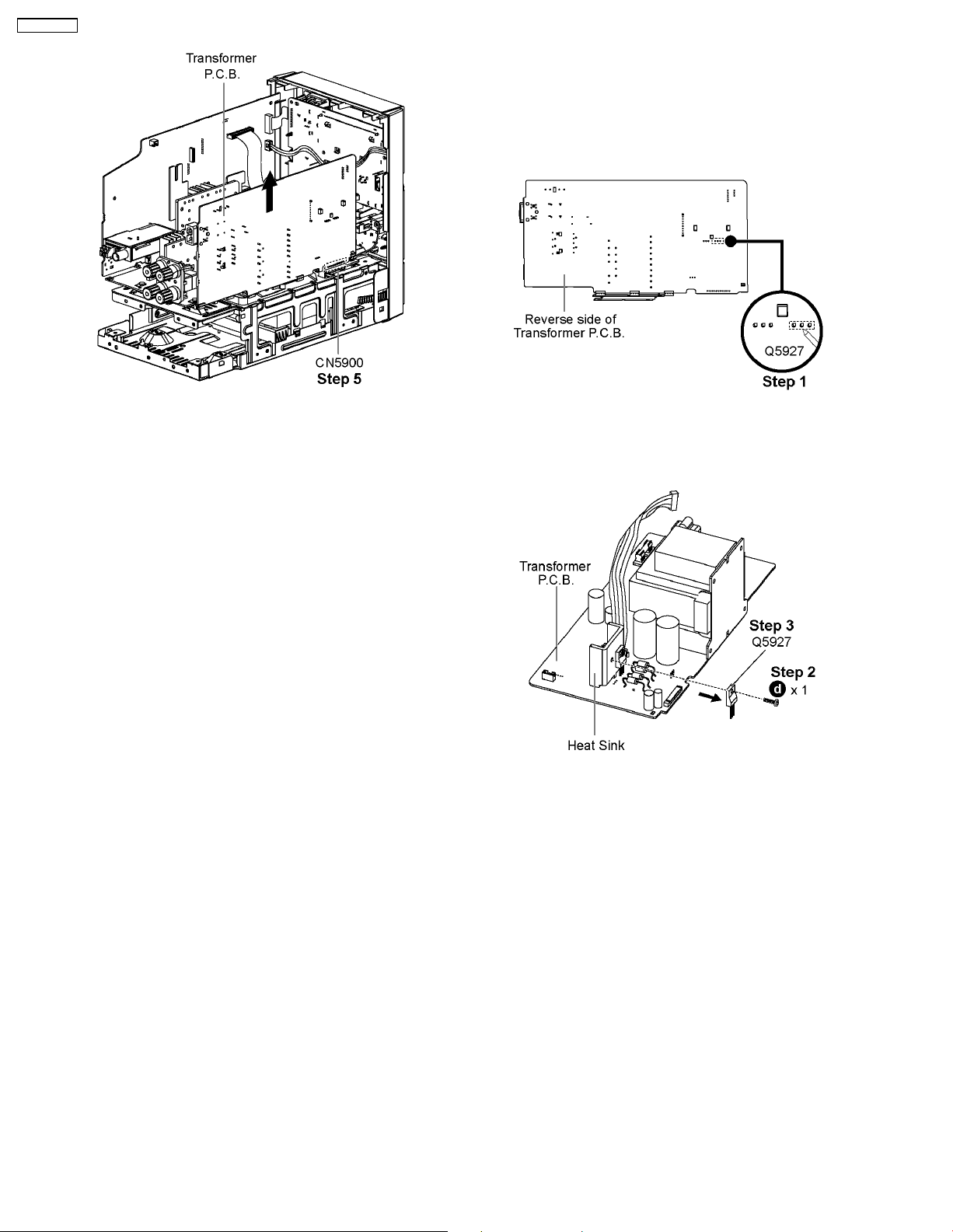
8.13. Replacement of Transistor
(Q5927)
• Follow the (Step 1) - (Step 5) of Item 8.3
• Follow the (Step 1) - (Step 6) of Item 8.9
• Follow the (Step 1) - (Step 5) of Item 8.12
Step 5 : Lift up to remove Transformer P.C.B..
Note: During reassembling procedures, ensure the 8P
cable is properly dresse d into the Support P.C.B..
Step 1 : Desolder pins of Transistor (Q5927) on reverse side of
Transformer P.C.B..
Step 2 : Remove 1 screw.
Step 3 : Remove the Transistor (Q5927).
Caution : Avoid touching the Heat Sink during replacement
due to its hight temperature as it may lead to injuries/shock.
28
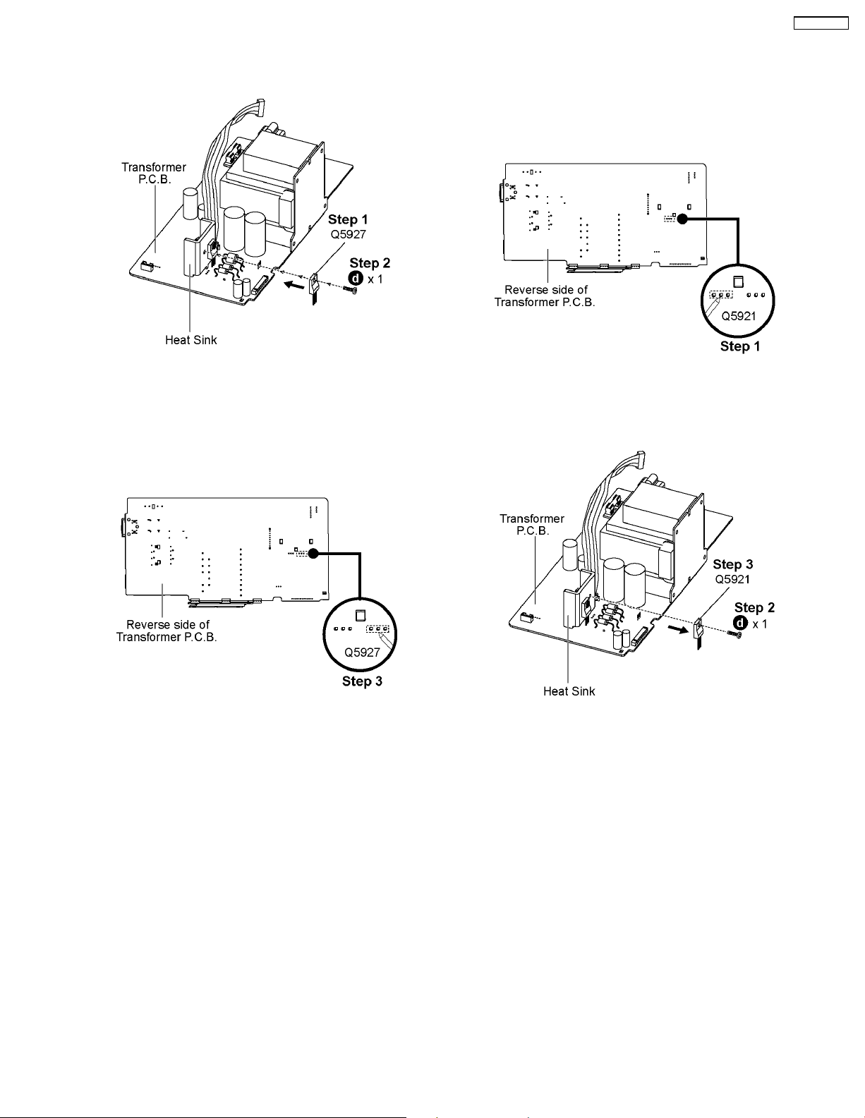
8.13.1. Assembly of the Transistor
(Q5927)
SA-PMX3GN
8.14. Replacement of Transistor
(Q5921)
• Follow the (Step 1) - (Step 5) of Item 8.3
• Follow the (Step 1) - (Step 6) of Item 8.9
• Follow the (Step 1) - (Step 5) of Item 8.12
Step 1 : Mount the transistor (Q5927) onto the Transformer
P.C.B..
Caution : Ensure all pins are seated properly.
Step 2 : Fix 1 screw to attach the transistor (Q5927) to the Heat
Sink.
Step 3 : Solder the pins of the Transistor (Q5927) on the
reverse side of the transformer P.C.B..
Caution : Before soldering, ensure all pins are properly seated
and no ‘floating’ of pins.
Step 1 : Desolder pins of Transistor (Q5921) on reverse side of
Transformer P.C.B..
Step 2 : Remove 1 screw.
Step 3 : Remove the Transistor (Q5921).
Caution : Avoid touching the Heat Sink during replacement
due to its hight temperature as it may lead to injuries/shock.
29
SA-PMX3GN
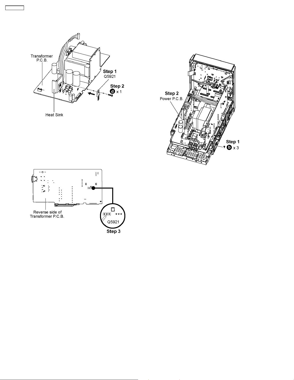
8.14.1. Assembly of the Transistor
(Q5921)
Step 1 : Mount the transistor (Q5921) onto the Transformer
P.C.B..
Caution : Ensure all pins are seated properly.
Step 2 : Fix 1 screw to attach the transistor (Q5921) to the Heat
Sink.
8.15. Disassembly of Power P.C.B.
• Follow the (Step 1) - (Step 5) of Item 8.3
• Follow the (Step 1) - (Step 6) of Item 8.9
• Follow the (Step 1) - (Step 7) of Item 8.11
• Follow the (Step 1) - (Step 2) of Item 8.12
Step 3 : Solder the pins of the Transistor (Q5921) on the
reverse side of the transformer P.C.B..
Caution : Before soldering, ensure all pins are properly seated
and no ‘floating’ of pins.
Step 1 : Remove 3 screws on Power P.C.B..
Step 2 : Remove Power P.C.B..
30
 Loading...