

Panasonic SAPM-71-SDGN Service manual
A
ORDER NO. MD0504156C3
CD Stereo System
SA-PM71SDGN
SA-PM71SDGT
Colour
(S)... Silver Type
Specification
n Amplifier Section
RMS output power, both channels driven
10%, Total harmonic distortion
1 kHz (Low channel) 40 W per channel
(6 Ω)
8 kHz (High channel) 40 W per channel
(6 Ω)
Total Bi-Amp power 80 W per channel
Output Impedance
Headphone 16Ω -32Ω
n FM Tuner Section
Frequency range 87.50 MHz to 108.00 MHz
(50 kHz steps)
Sensitivity 1.50 µV (IHF)
S/N 26dB 1.70 µV
ntenna terminals 75 Ω (unbalanced)
Preset stations 15
n AM Tuner Section
Frequency range 522 kHz to 1629 kHz (Default)
(9 kHz steps)
520 kHz to 1630 kHz
(10 kHz steps)
Sensitivity S/N 20 dB at 999 kHz 560 µV/m
Preset stations 15
n Cassette Deck Section
Track system 4 track, 2 channel
Heads
Record/playback Solid permalloy head
Erasure Double gap ferrite head
Motor DC servo motor
Recording system AC bias 100 kHz
Erase system AC erase 100 kHz
Tape speed 4.8cm/s(1-7/8ips)
Overall frequency response (+3 dB, -6 dB) at DECK OUT
Normal 35 Hz to 14 kHz
Wow and flutter 0.10% (WRMS)
Fast forward and rewind time Approx. 120 seconds with C-60
cassette tape
n CD Section
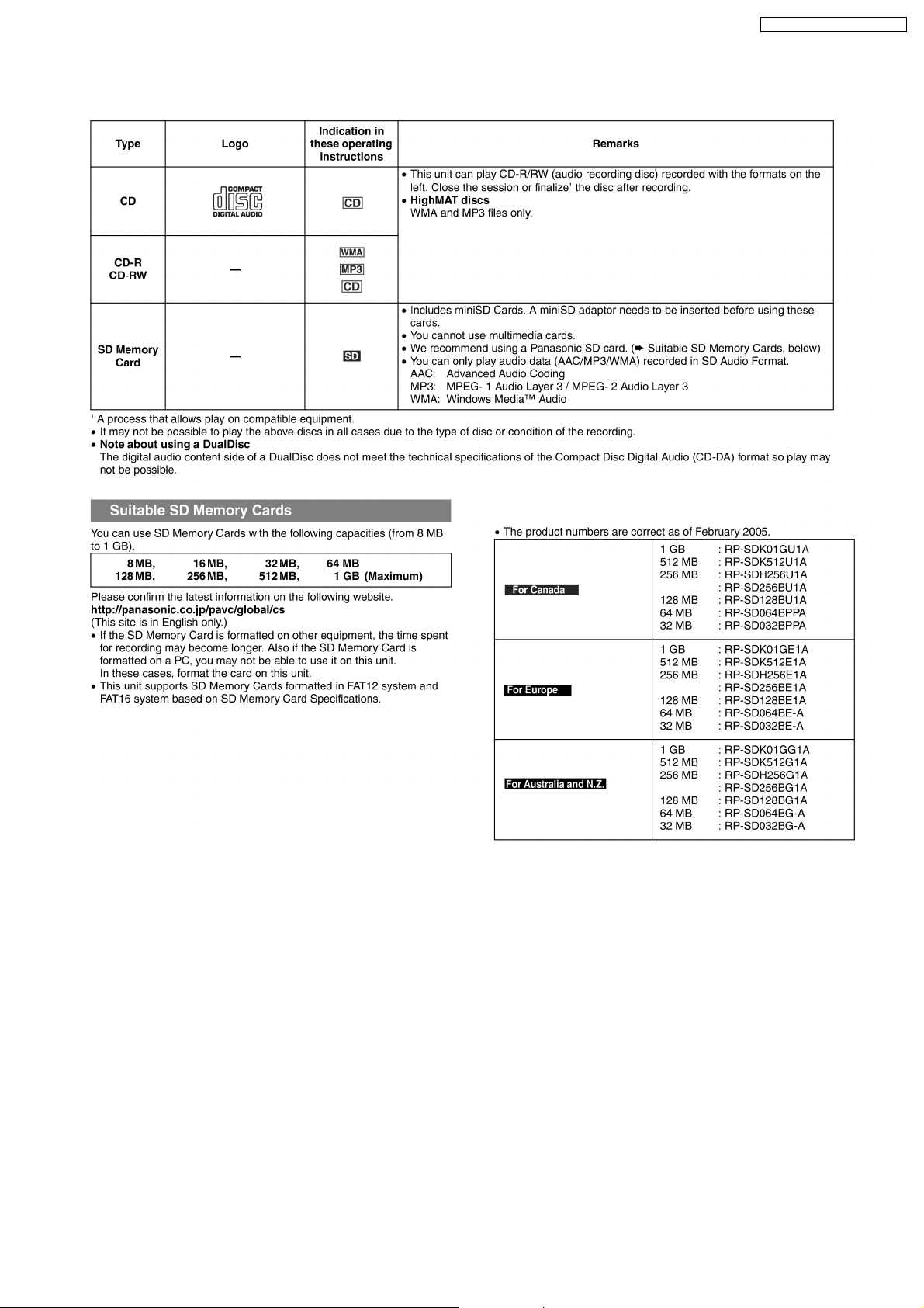
Disc CD,MP3,WMA,CD-R/RW,
HighMat
8cm (3”) / 12 cm (5”)
Sampling frequency
CD 44.1 kHz
MP3/WMA 32 kHz, 44.1 kHz, 48 kHz
Bit rate
MP3 32 kbps to 320 kbps
WMA 40 kbps to 192 kbps
Decoding 16 bit linear
Pickup
Beam source Semiconductor laser
Wavelength 780 nm
Number of channels Stereo
Frequency response 20 Hz to 20 kHz (+1dB, -2 dB)
© 2005 Matsushita Electric Industrial Co. Ltd.. All
rights reserved. Unauthorized copying and
distribution is a violation of law.
SA-PM71SDGN / SA-PM71SDGT
Wow and flutter Below measurable limit
Digital filter 8fs
D/A converter MASH (1 bit DAC)
n SD Section
Sampling frequency 32 kHz (LP), 44.1 kHz (SP,XP)
Coding system
SD Audio Playback AAC, MP3, W MA
SD Audio Record AAC
Number of channels 2 channel (stereo)
n Other
CD → SD Recording speed Maximum 4 times (LP)
n General
Power supply AC 230 - 240 V, 50 Hz (For GN)
AC 110 V, 60 Hz (For GT)
Max. power consumption 248 W (1% total harmonic
distortion) (For GT)
Power consumption 130 W
Dimensions (W x H x D) 175 mm x 249.5 mm x 379.6 mm
(6 29/32 x 9 27/32” x 14 31/32”)
Mass 5.8 kg (12.8 Ibs)
Power consumption in standby
mode
Notes :
1. Specifications are subject to change without notices. Mass and
dimensions are approximate.
2. Total harmonic distortion is measured by the digital spectrum
analyzer.
n System : SC-PM71SDGN-S
n System : SC-PM71SDGTS
Music center: SA-PM71SDGN-S
Music center: SA-PM71SDGTS
0.5 W (For GN)
0.3 W (For GT)
Speaker: SB-PM71P-M
Speaker: SB-PM71P-M
CONTENTS
Page Page
1 Safety Precautions
1.1. GENERAL GUIDELINES
2 Before Repair and Adjustment
3 Protection Circuitry
4 Handling the Lead-free Solder
4.1. About lead free solder (PbF)
5 Precaution of Laser Diode
6 Handling Precautions For Traverse Deck
7 Accessories
8 Operation Procedures
8.1. Main Unit
8.2. Remote Control
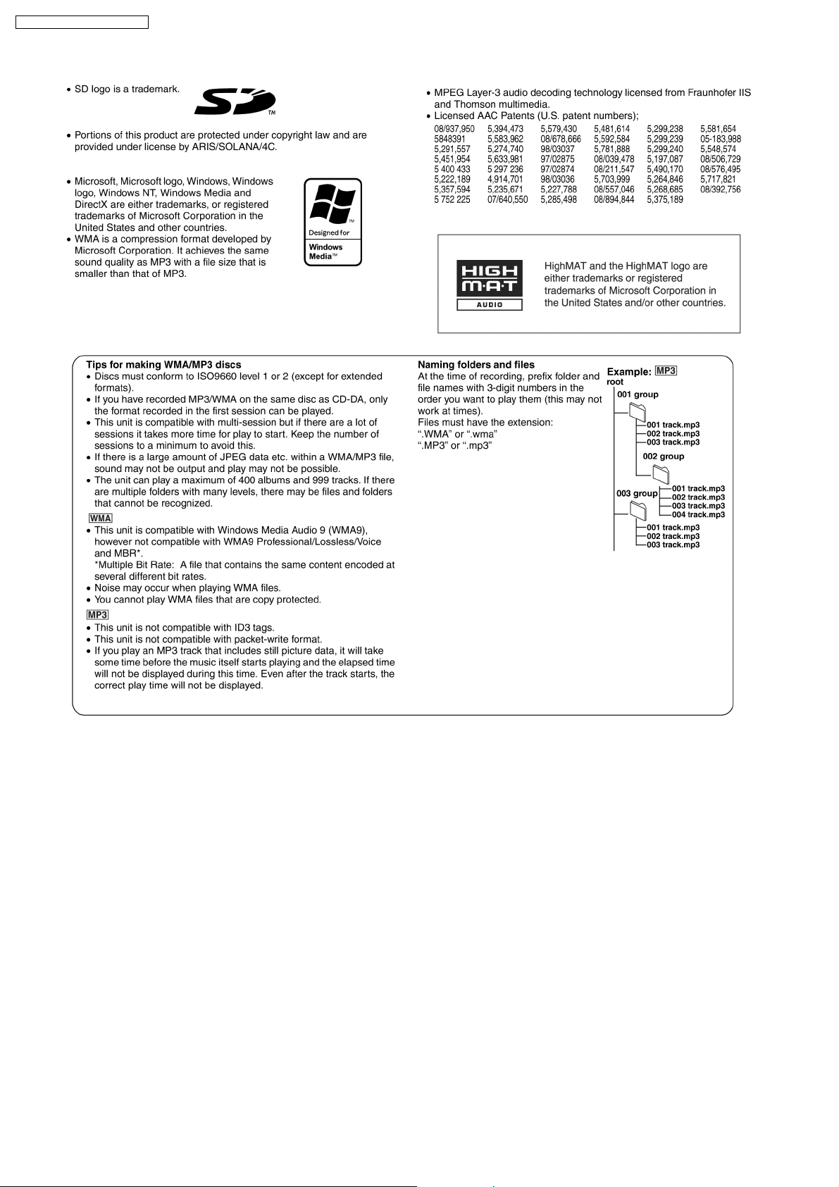
9 Information on Disc & MP3
10 SD Card Information
11 About HighMAT
11.1. What 痴 HighMAT?
11.2. Why take advantage of HighMAT?
11.3. Benefits of HighMAT?
12 Assembling and Disassembling
12.1. Disassembly flow chart
12.2. Disassembly of Side Panel L & R
12.3. Disassembly of Top Cabinet
12.4. Disassembly of Deck Mechanism P.C.B. and Tape Eject
P.C.B.
12.5. Disassembly of Front Panel
12.6. Disassembly of SD Module P.C.B.
12.7. Disassembly of Panel P.C.B.
12.8. Disassembly of Rear Cabinet
12.9. Disassembly of Main P.C.B.
4
4
5
5
5
5
6
7
8
9
9
10
11
13
15
15
15
16
19
19
20
20
20
21
22
22
23
24
12.10. Disassembly of Transforme r P.C.B.
12.11. Disassembly of Tuner Pack
12.12. Disassembly of Power P.C.B.
12.13. Disassembly of CR16 Mechanism
12.14. Replacement of CD Lid and Inner CD Lid
12.15. Replacement of Cassette Lid
12.16. Replacement of the Power IC and Transistors
12.17. Procedure for Replacing Pinch Roller and Head Block
(Deck Mechanism Unit)
12.18. Procedure for Replacing Motor, Capstan Belt A, Capstan
Belt B, and Winding Belt (Deck Mechanism Unit)
12.19. Procedure for Replacing Parts on Deck Mechanism PCB
12.20. Disassembly of CR16 Mechanism
12.21. Replacement of optical pickup unit (CD mechanism)
12.22. Replacement of a traverse gear A and a traverse gear B
12.23. Procedure for removing CD loading mechanism
12.24. CR16 mechanism disassembly procedure
12.25. CR16 MECHANISM ASSEMBLY PROCEDURE
12.26. Disassembly of traverse mechanism
12.27. Handling of cassette tape jam
13 Service Positions
13.1. Checking procedure
13.2. Checking the major P.C.B
14 Self-Diagnostic Display Function
14.1. Entering into Self-Diagnostic Mode
14.2. Error Code Table
14.3. Changer Reliability Test Mode
24
25
25
25
26
28
28
30
30
32
32
33
35
36
36
42
55
56
57
57
57
58
58
59
60
2
SA-PM71SDGN / SA-PM71SDGT
15 Procedure for Checking Operation of Individual Parts of Deck
Mechanism Unit
15.1. Operation Check with Cassette Tape
15.2. Operation Check without Cassette Tape
16 Measurement And Adjustments
16.1. Cassette Deck Section
17 Voltage Measurement and Waveform Chart
17.1. Voltage Measurement
17.2. Waveform Chart
18 Block Diagram
18.1. CD SERVO Block
18.2. MAIN Block
19 Notes of Schematic Diagram
20 Schematic Diagram
20.1. CD SERVO CIRCUIT
20.2. SD MODULE CIRCUIT
20.3. MAIN CIRCUIT
20.4. PANEL CIRCUIT and TRANSFORMER CIRCUIT
20.5. POWER CIRCUIT
61
61
61
63
63
65
65
71
73
73
75
82
83
83
85
90
95
97
20.6. DECK CIRCUIT, DECK MECHANISM CIRCUIT and TAPE
EJECT CIRCUIT
20.7. CD LOADING CIRCUIT
21 Printed Circuit Board
99
101
102
21.1. CD SERVO P.C.B
21.2. SD MODULE P.C.B
21.3. MAIN P.C.B
21.4. PANEL P.C.B
21.5. TRANSFORMER P.C.B
21.6. POWER P.C.B
21.7. DECK P.C.B and TAPE EJECT P.C.B
21.8. DECK MECHANISM P.C.B and CD LOADING P.C.B
22 Wiring Connection Diagram
23 Illustration of IC 痴, Transistors and Diodes
24 Terminal Function of ICエs
24.1. IC807 (MN103SF77RXW) IC SD Audio Drive Controller
24.2. IC703 (BA5948FPE2) IC 4CH Drive
25 Troubleshooting Flowchart (CD Section Circuit)
26 Troubleshooting Flowchart (SD Card Section Circuit)
27 Parts Location and Replacement Parts List
27.1. Deck Mechanism
27.2. CD LOading Mechanisms
27.3. Cabinet Part List
27.4. Electrical Part List
27.5. Packaging Materials & Accessories Parts List
27.6. Packaging
102
104
105
107
108
109
110
111
112
114
115
115
116
117
119
121
122
124
129
133
144
144
3
SA-PM71SDGN / SA-PM71SDGT
1 Safety Precautions
1.1. GENERAL GUIDELINES
1. When servicing, observe the original lead dress. If a short circuit is found, replace all parts which have been overheated or
damaged by the short circuit.
2. After servicing, ensure that all the protective devices such as insulation barriers, insulation papers shields are properly installed.
3. After servicing, check for leakage current checks to prevent from being exposed to shock hazards.
1.1.1. LEAKAGE CURRENT COLD CHECK
1. Unplug the AC cord and connect a jumper between the two prongs on the plug.
2. Using an ohmmeter measure the resistance value, between the jumpered AC plug and each expose d metallic cabinet part on
the equipment such as screwheads, connectors, control shafts, etc. When the exposed metallic part has a return path to the
chassis, the reading should be between 1MΩand 5.2Ω.
When the exposed metal does not have a return path to the chassis, the reading must be
.
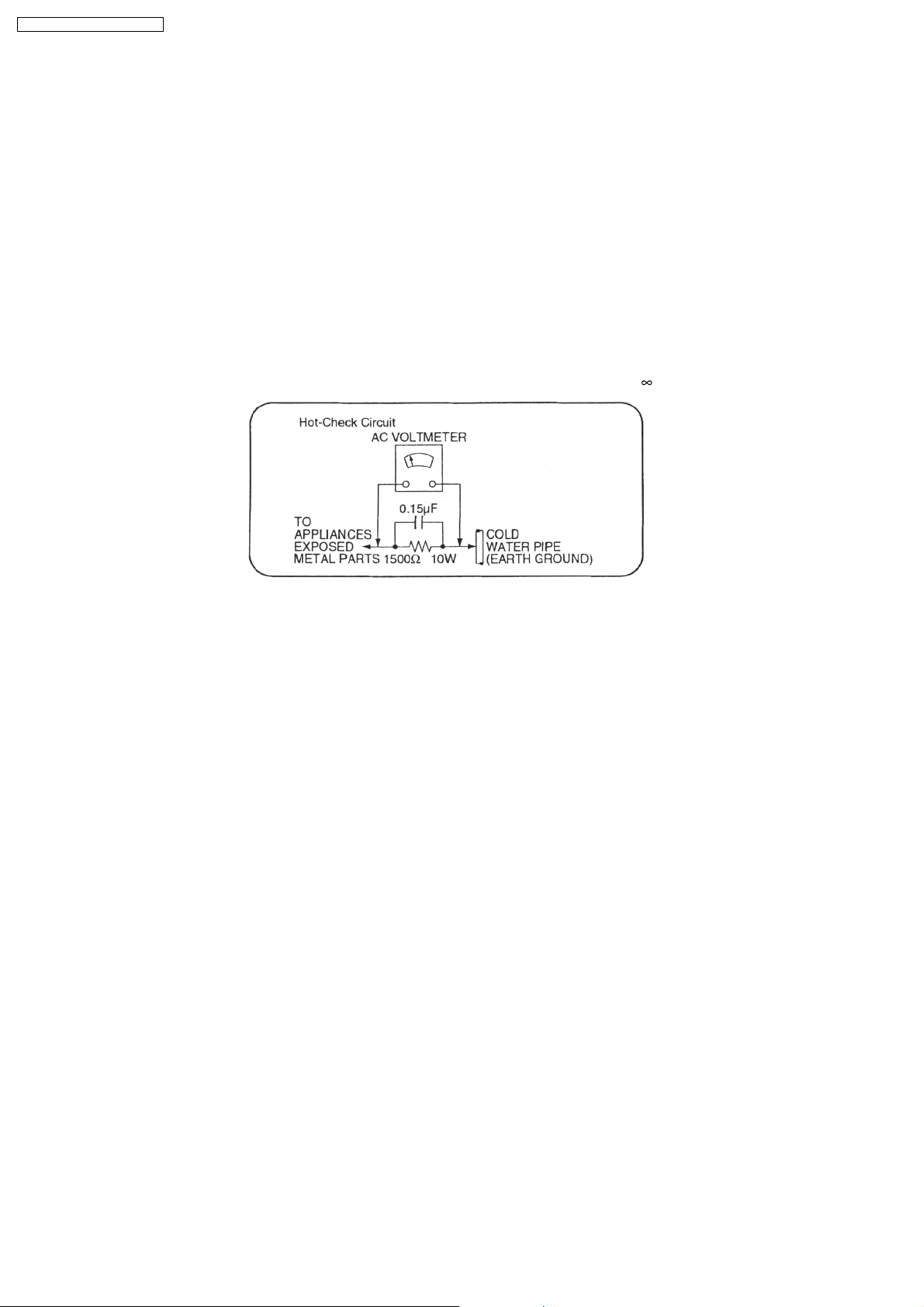
Fig. 1
1.1.2. LEAKAGE CURRENT HOT CHECK (See Figure 1.)
1. Plug the AC cord directly into the AC outlet. Do not use an isolatio n transfo rmer for this check.
2. Connect a 1.5kΩ, 10 watts resistor, in parallel with a 0.15µF capacitors, between each exposed metallic part on the set and a
good earth ground such as a water pipe, as shown in Figure 1.
3. Use an AC voltmeter, with 1000 ohms/volt or more sensitivity, to measure the potential across the resistor.
4. Check each exposed metallic part, and measure the voltage at each point.
5. Reverse the AC plug in the AC outlet and repeat each of the above measurements.
6. The potential at any point should not exceed 0.75 volts RMS. A leakage current tester (Simpson Model 229 or equivalent) may
be used to make the hot checks, leakage current must not exceed 1/2 milliamp. should the measurement is outside of the limits
specified, there is a possibility of a shock hazard, and the equipment should be repaired and re-checked before it is returned
to the customer.
4

SA-PM71SDGN / SA-PM71SDGT
2 Before Repair and Adjustment
Disconnect AC power, discharge Power Supply Capacitors C448, C449, C452, C455, C456, C506, C507, C508 & C584 through
a10Ω, 1W resistor to ground.
DO NOT SHORT-CIRCUIT DIRECTLY (with a screwdriver blade, for instance), as this may destroy solid state devices.
After repairs are completed, restore power gradually using a variac, to avoid overcurrent.
· Current consumption at AC 230V-2 40V, 50 Hz in NO SIGNAL mode should be ~300 mA. (For GN)
· Current consumption at AC 110V, 60 Hz in NO SIGNAL mode should be ~350 mA. (For GT)
3 Protection Circuitry
The protection circuitry may have operated if either of the following conditions are noticed:
· No sound is heard when the power is turned on.
· Sound stops during a performance.
The function of this circuitry is to prevent circuitry damage if, for example, the positive and negative speaker connection wires are
"shorted", or if speaker systems with an impedance less than the indicated rated impedance of the amplifier are used.
If this occurs, follow the procedure outline s below:
1. Turn off the power.
2. Determine the cause of the problem and correct it.
3. Turn on the power once again after one minute.
Note:
When the protection circuitry functions, the unit will not operate unless the power is first turned off and then on again.
4 Handling the Lead-free Solder
4.1. About lead free solder (PbF)
Distinction of PbF P.C.B.:
P.C.B.s (manufactured) using lead free solder will have a PbF stamp on the P.C.B.
Caution:
· Pb free solder has a higher melting point than standard solder; Typically the melting point is 50 - 70°F (30 - 40°C) higher. Please
use a high temperature soldering iron. In case of soldering iron with temperature control, please set it to 700 ± 20°F (370 ±
10°C).
· Pb free solder will tend to splash when heated too high (about 1100°F/600°C).
· W hen soldering or unsoldering, please completely remove all of the solder on the pins or solder area, and be sure to heat the
soldering points with the Pb free solder until it melts enough.
5

SA-PM71SDGN / SA-PM71SDGT
5 Precaution of Laser Diode
CAUTION:
This unit utilizes a class 1 laser.
Invisible laser radiation is emitted from the optical pickup lens.
When the unit is turned on:
1. Do not look directly into the pick up lens.
2. Do not use optical instruments to look at the pick up lens.
3. Do not adjust the preset variable resistor on the pickup lens.
4. Do not disassemble the optical pick up unit.
5. If the optical pick up is replaced, use the manufacturer’s specified replacement pick up only.
6. Use of control or adjustments or performance of procedures other than those specified herein may result in hazardous radiation
exposure.
CAUTION!
THIS PRODUCT UTILIZES A LASER.
USE OF CONTROLS OR ADJUSTMENTS OR PERFORMANCE OF PROCEDURES OTHER THAN THOSE SPECIFIED HEREIN MAY RESULT
IN HAZARDOUS RADIATION EXPOSURE.
6
SA-PM71SDGN / SA-PM71SDGT
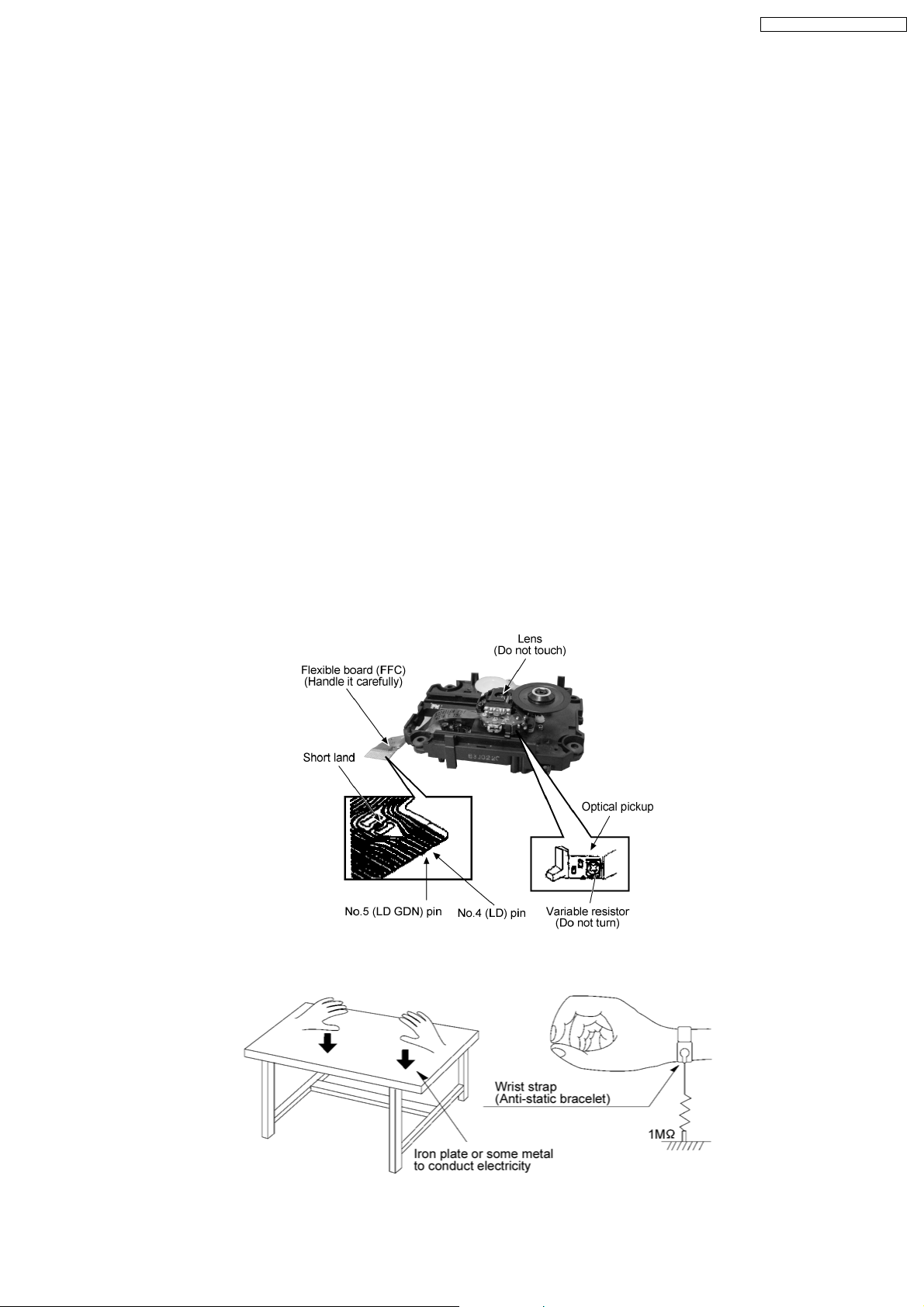
6 Handling Precautions For Traverse Deck
The laser diode in the traverse deck (optical pickup) may break down due to potential difference caused by static electricity of
clothes or human body. So, be careful of electrostatic breakdown during repair of the traverse deck (optical pickup).
· Handling of traverse deck (optical pickup)
1. Do not subject the traverse deck (optical pickup) to static electricity as it is extremely sensitive to electrical shock.
2. To prevent the breakdown of the laser diode, an antistatic shorting pin is inserted into the flexible board (FFC board).
3. Take care not to apply excessive stress to the flexible board (FFC board). When removing or connecting the short pin, finish
the job in as short time as possible. (Fig 6.1)
4. Do not turn the variable resistor (laser power adjustment). It has already been adjusted.
· Grounding for electrostatic breakdown prevention
1. Work table grounding. (Fig 6.2)
Use the anti-static wrist strap to discharge the static electricity from your body.
2. Work table grounding. (Fig 6.2)
Put a conductive material (sheet) or steel sheet on the area where the traverse deck (optical pickup) is place, and ground
the sheet.
Caution:
The static electricity of your clothes will not be grounded through the wrist strap. So, take care not to let your clothes touch the
traverse deck (optical pickup).
Caution when replacing the Traverse Deck
The traverse deck has a short point shorted with solder to protect the laser diode against electrostatics breakdown. Be sure to
remove the solder from the short point before making connections.
(Fig 6.1)
(Figs 6.2)
7
SA-PM71SDGN / SA-PM71SDGT
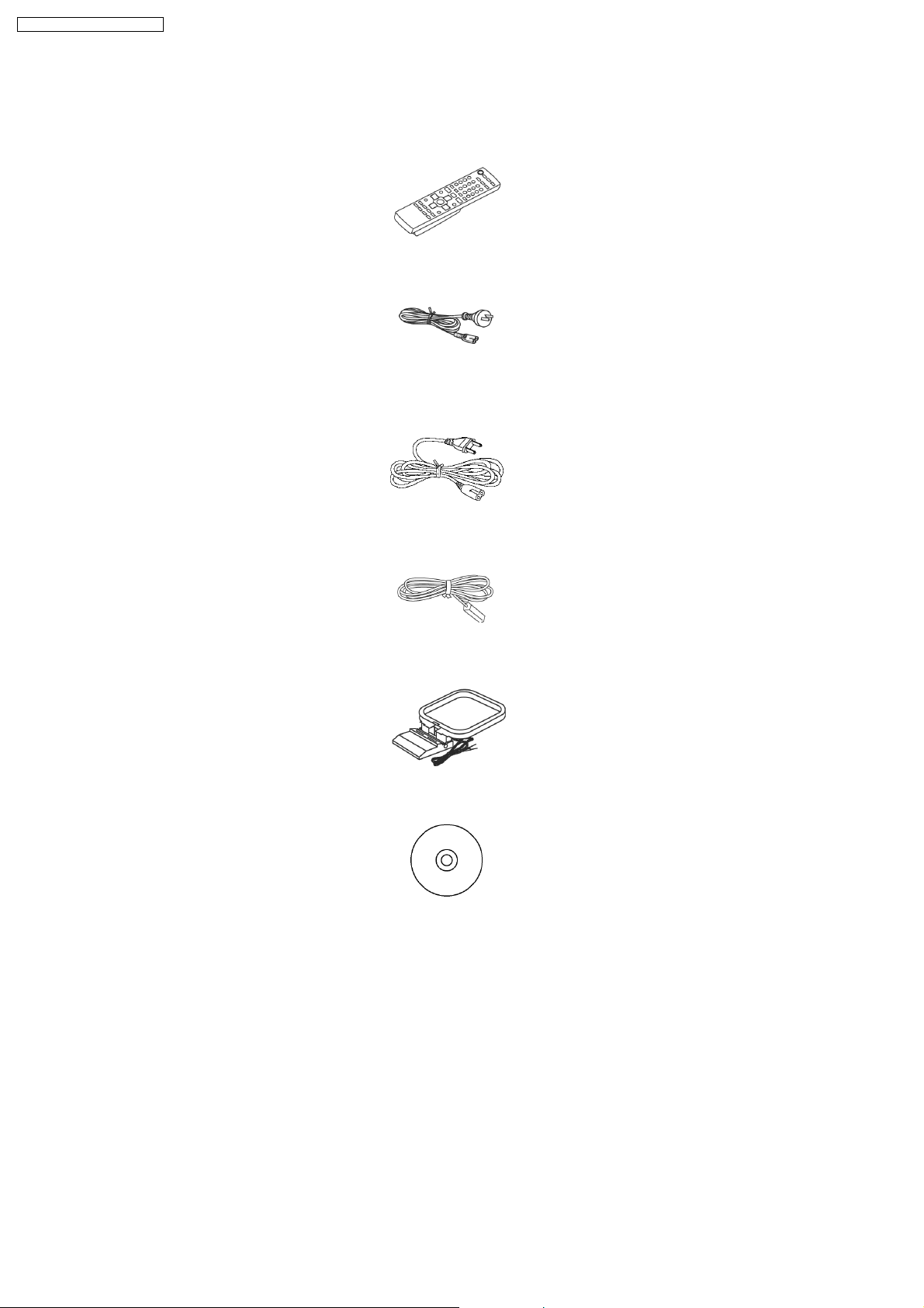
7 Accessories
Note : Refer to Packing Materials & Accessories Parts List (Section 27.5) for the part number.
Remote Control
AC cord (For GN
only)
AC cord (For GT only)
FM indoor antenna
AM loop antenna
CD ROM
(For GN
only)
8
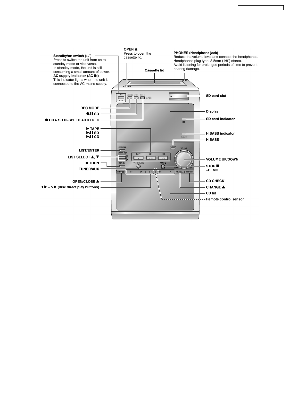
8 Operation Procedures
8.1. Main Unit
SA-PM71SDGN / SA-PM71SDGT
9
SA-PM71SDGN / SA-PM71SDGT
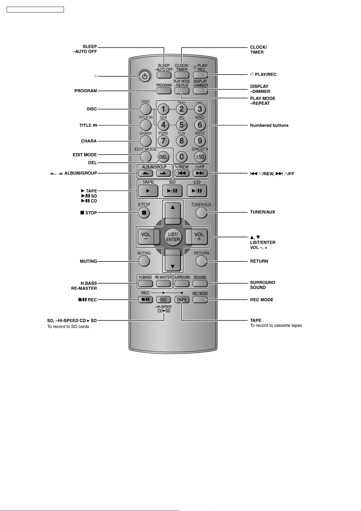
8.2. Remote Control
10
9 Information on Disc & MP3
SA-PM71SDGN / SA-PM71SDGT
11
SA-PM71SDGN / SA-PM71SDGT
12
SA-PM71SDGN / SA-PM71SDGT
10 SD Card Information
A New Lifestyle is Evolving with the SD Memory Card
The SD Memory Card is at the heart of many Panasonic products. It´s a high-capacity, high-speed storage medium for the digital
age. Incredibly small yet durable, the SD Memory Card is about the size of a postage stamp. It can store all kinds of digital content,
like video, still images, music and more! So you can transfer data easily between products with an SD Card slot.
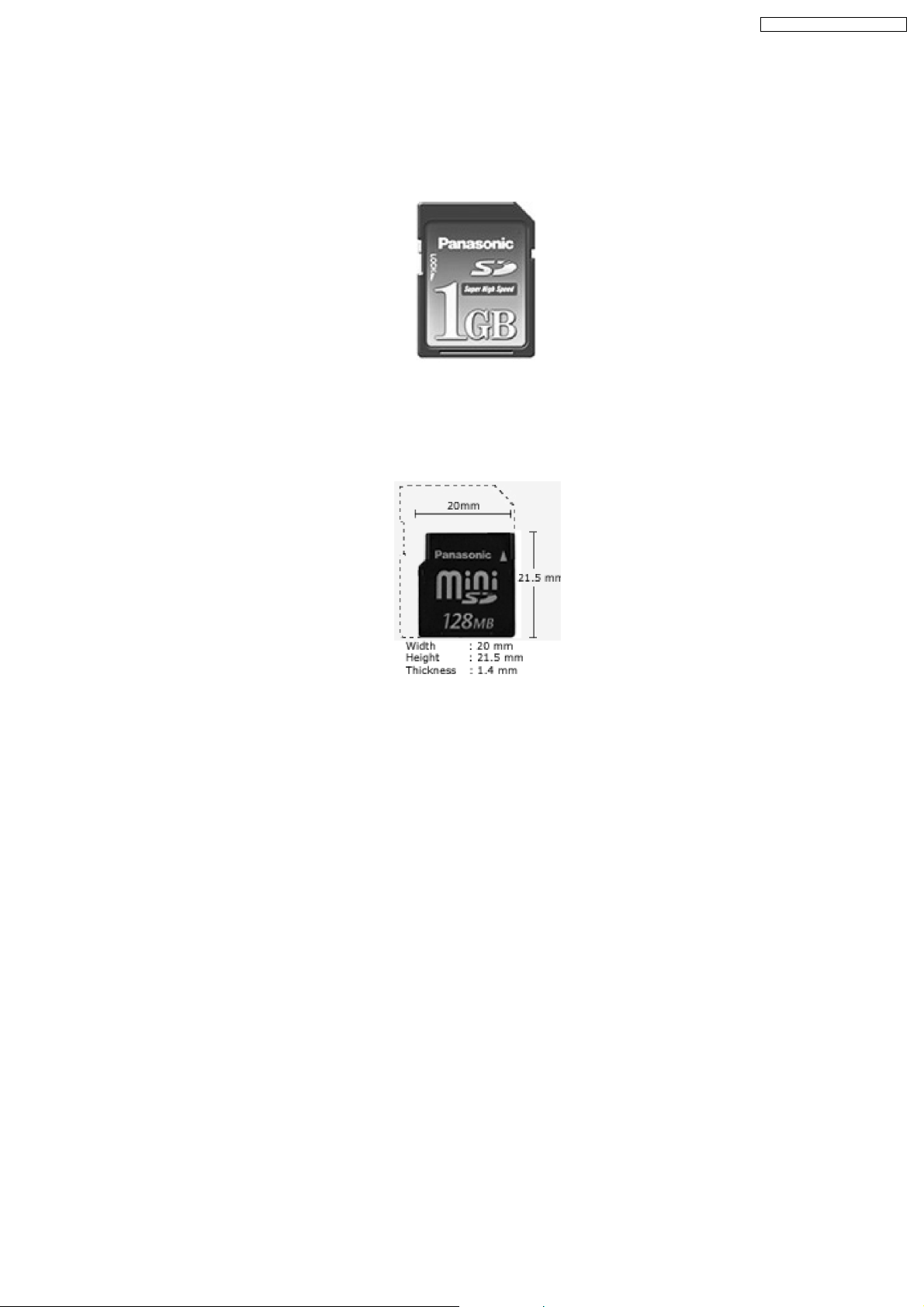
The miniSD card
The miniSD card was developed to meet industry deman ds for a memory card small enough for today’s compact mobile phones.
It is about 40% smaller than a Panasonic SD Memory Card, but offers all the benefits-including copyright protection. Each miniSD
card comes with an adapter that makes the miniSD card compatible with standard SD-enabled products.
Ideal for MPEG2 Video Recording
The increasing data volume and expand ing range of digital contents require high data reading and writing speeds. Panasonic SD
Memory Cards, 256MB
1
and higher, achieve the data writing speed fast enough to record MPEG2 video in fine mode.
Compact & Slim
The SD Memory Card measures a mere 0.94" x 1.26" x .08" (24mm x 32mm x 2.1mm). Its slim, compact design promotes easy
handling-an important factor for moving between differe nt SD-compatible products. Our SD Memory Cards are small enough to be
used in select mobile phones and PDAs, as well as many other compact or multi-functional products.
Large Capacity
SD Memory Cards are currently available in several capacities up to 1GB
2
. Be on the lookout in the near future for 2GB2and 4GB
cards. This kind of large capacity is essential for use with various digital content types, especially high-quality MPEG2 video.
Fast Access
Providing quick response and effortless handling of digital content, SD Memory Cards 256MB
1
and higher can write data fast
enough to record high-quality MPEG2 video in fine mode.
Copyright Protection
The copyright protection technology used for the SD Memory Card, Content Protection for Recordable Media (CPRM), is the key
to enabling a new distribution system for music and other commercial media. CPRM assures a high level of protection against
illegal copying and was developed by 4C (The digital contents copyright protection technology licensing organization of IBM, Intel,
Matsushita, and Toshiba.).
2
This protection is enhanced in the SD Memory Card through the use of key revocation technology that is built into the card. The
13
SA-PM71SDGN / SA-PM71SDGT
card´s control circuitry allows data to be read and written, in its protection area only when appropriate external devices are detected.
Copying data ("checking-out") from a PC to an SD Memory Card is restricted to three copies in compliance with the SDMI
specification.
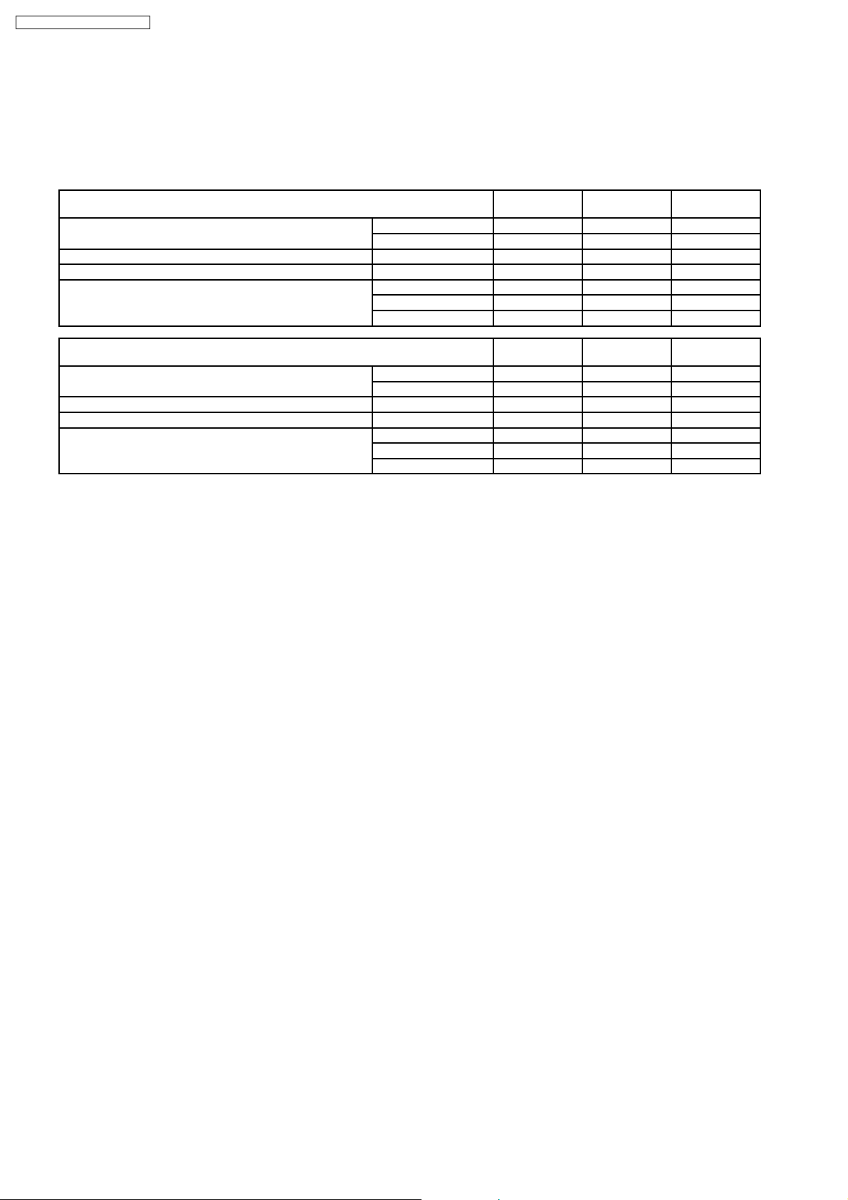
Comparison chart
File Type 1GB
2
Approx. Number of JPEG Photos3(1,600 x 1,200) Standard 2325 1209 600
Fine 1162 604 300
Approx. Time of MPEG4 Video (Using the D-snap SV-AV50) 384 Kbps, 12 fps 370 min. 180 min. 90 min.
Approx. Time of MPEG2 Video (Using the D-snap SV-AV100) 6 Mbps, 30 fp3 20 min. 10 min. 5 min.
Approx. Time of Recording Capacity for Music
(AAC/MP3/WMA)
4
High Quality (128kbps) 8h. 44 min. 4h. 20 min.
Normal (96kbps) 11h. 38 min. 5h. 46 min.
Long Play (64kbps) 17h. 28 min. 8h. 40 min.
File Type 128MB
1
Approx. Number of JPEG Photos3(1,600 x 1,200) Standard 301 149 72
Fine 150 74 36
Approx. Time of MPEG4 Video (Using the D-snap SV-AV50) 384 Kbps, 12 fps 40 min. 20 min. 10 min.
Approx. Time of MPEG2 Video (Using the D-snap SV-AV100) 6 Mbps, 30 fp3 N/A N/A N/A
Approx. Time of Recording Capacity for Music
(AAC/MP3/WMA)
4
High Quality (128kbps) 2h. 10 min. 1h. 4 min. 31 min.
Normal (96kbps) 2h. 54 min. 1h. 26 min. 42 min.
Long Play (64kbps) 4h. 21 min. 2h. 9 min. 1h. 3 min.
512MB
64MB
1
1
256MB
32MB
1
1
For Notes
1. MB = 1 million bytes. Usable capacity will be less.
2. GB = 1 billion bytes. Usable capacity will be less.
3. For normal shooting of 1,600 x 1,200 /static/Content. These figures vary depending on the subject being photographed and
on the particular model.
4. Approximate recording time in AAC format.
14

SA-PM71SDGN / SA-PM71SDGT
11 About HighMAT
11.1. What’s HighMAT?
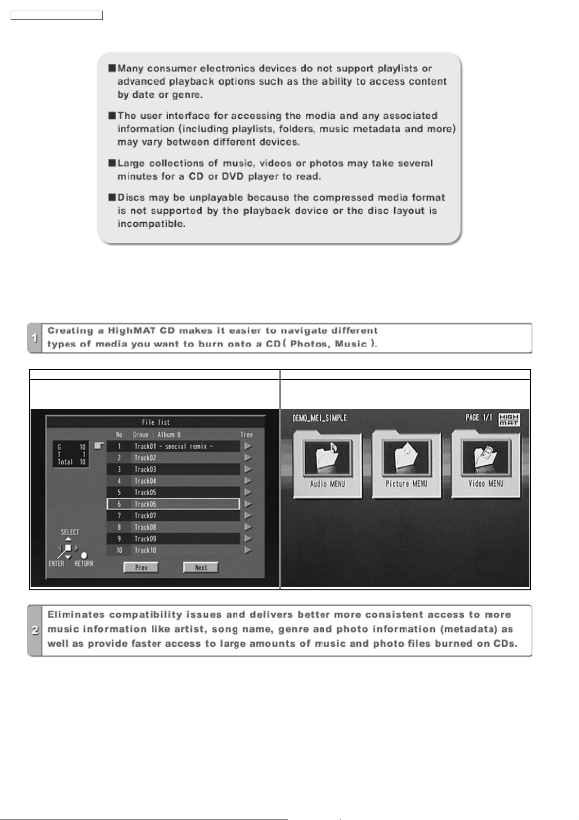
Consumers worldwide are using PCs to create their own collections of music, photos and even video by burning them onto CDs.
But how these collections can be experie nced across different devices can be confusing to navigate, time consuming to access for
a DVD player, and be incomplete in terms of music information available to the customer.
HighMAT offers a solution to this growing consumer problem. HighMAT dramatically improves the digital media experience on
consumer electronic devices by delivering a simple, standardized approach that allows consumers who have created personal
collections of digital music, photography and video on their PC to:
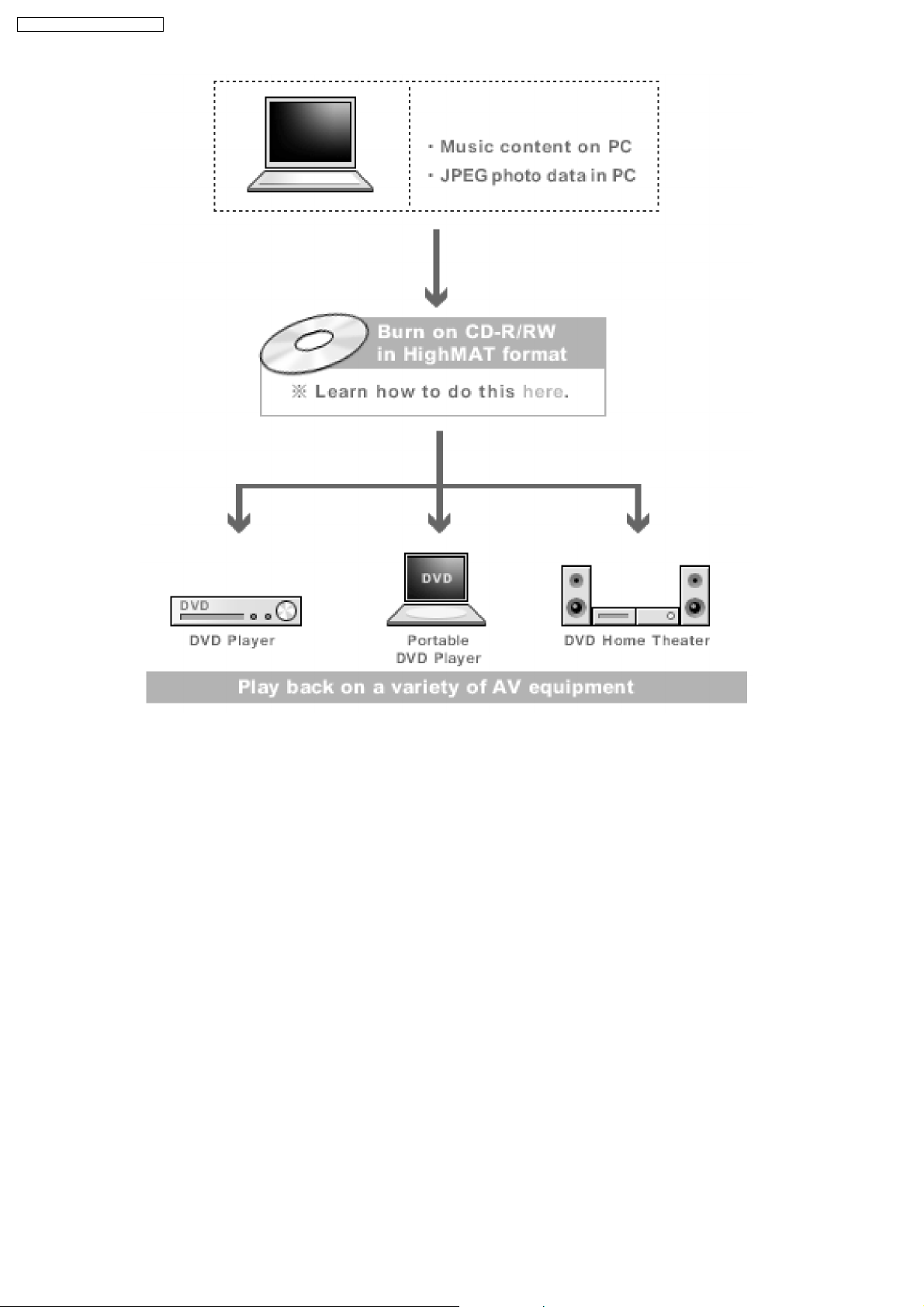
· Create a HighMAT CD or DVD which can be easily played back on consum er electronics devices such as CD and DVD players,
and car stereos.
· Move digital media files (using recordable media such as CD-R and CD-RW) between the PC and various playback devices
such as CD and DVD players.
A new standard for creating personal media on consumer electronic devices, HighMAT enable easier and more seamless
interoperability between Windows PCs and devices designed for your living room, or the car.
11.2. Why take advantage of HighMAT?
A Problem Defined:Today, when consum ers create their own digital audio, video or photo collections on CD-R or other physical
formats, there are numerous, inconsistent ways that devices read the data. For the consumer, the playback experience can be
confusing:
15
SA-PM71SDGN / SA-PM71SDGT
A Solution Created: HighMAT delivers a better digital media access experience by creating a standard approach for PCs to
structure digital media on various physical formats and for playba ck devices to read the data.
11.3. Benefits of HighMAT?
Conventional HighMAT
Even though DVD player is CD-R/RW compatible, the inconsistent ways
that various DVD players can read the music or photos files often leads
to a confusing and inconsistant playback experince.
HighMAT compatible products play content back with consistent
interface. This includes products which are JPEG compatible products
without HighMAT support.
16
SA-PM71SDGN / SA-PM71SDGT
17
SA-PM71SDGN / SA-PM71SDGT
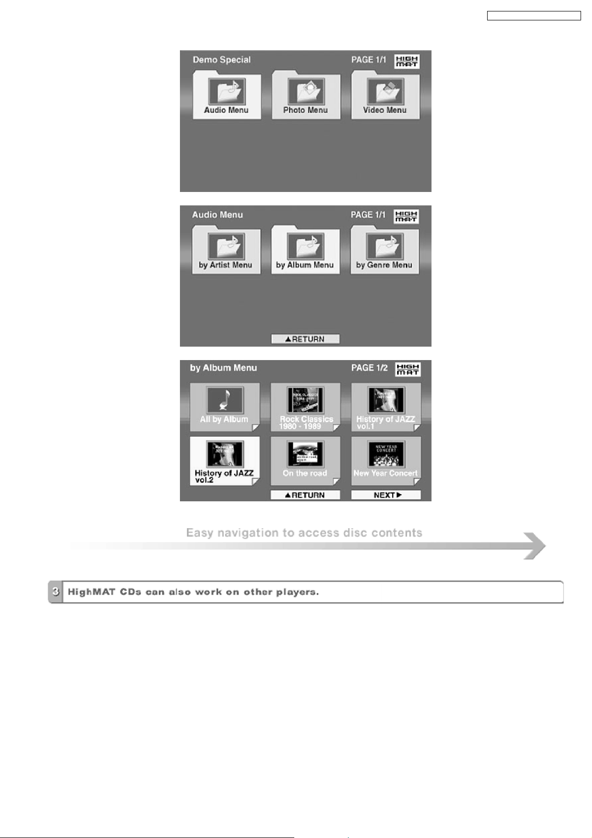
HighMAT is now available for CD Burning and in Leading DVD PlayersHighMAT is a new technology that is now available in leading
software and consumer electronic devices to dramatically improve the digital media experience when you create homemade
CDsHighMAT delivers a simple, standardized way for PC software and consum er electronics devices to talk to each other and work
better together.
When you create your homemade CDs with software that supports HighMAT CD burning, and then play them back on a DVD
player that supports HighMAT, you get better, easier navigation. You get folders you can access with a single click of your DVD
player´s remote control. You can view important information about your music like full song names, artist titles, album names and
genre. And you can get faster startup on your home entertainment device.
To enjoy the benefits of HighMAT, all you need is software that supports HighMAT for CD burning of music or photos, as well as
a home entertainment device like a DVD player that supports HighMAT for playback. Always look for the HighMAT logo on your
software or home entertainment device to ensure it supports the HighMAT experience.
18
SA-PM71SDGN / SA-PM71SDGT
12 Assembling and Disassembling
“ATTENTION SERVICER”
Some chassis components may be have sharp edges. Be careful when disassembling and servicing.
1. This section describes procedures for checking the operation of the major printed circuit boards and replacing the main
components.
2. For reassembly after operation checks or replacement, reverse the respective procedures.
Special reassembly procedures are described only when required.
3. Select items from the following index when checks or replacement are required.
· Disassembly of Side Panel L & R
· Disassembly of Top Cabinet
· Disassembly of Deck Mechanism P.C.B. and Tape Eject P.C.B.
· Disassembly of Front Panel
· Disassembly of SD Module P.C.B.
· Disassembly of Panel P.C.B.
· Disassembly of Rear Cabinet
· Disassembly of Main P.C.B.
· Disassembly of Transformer P.C.B.
· Disassembly of Tuner Pack
· Disassembly of Power P.C.B.
· Disassembly of CR16 Mechanism
Warning:
This product uses a laser diode. Refer to “Precaution of Laser Diode”.
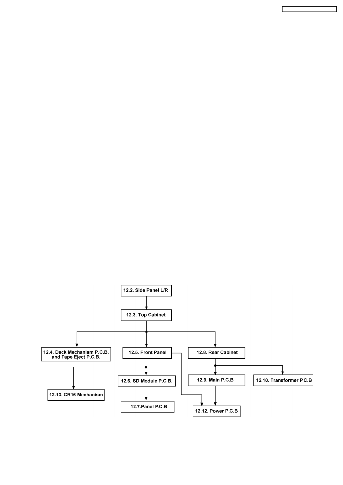
12.1. Disassembly flow chart
The following chart is the procedure for disassembling the casing and inside parts for internal inspection when carrying out the
servicing.
To assemble the unit, reverse the steps shown in the chart below.
19
SA-PM71SDGN / SA-PM71SDGT
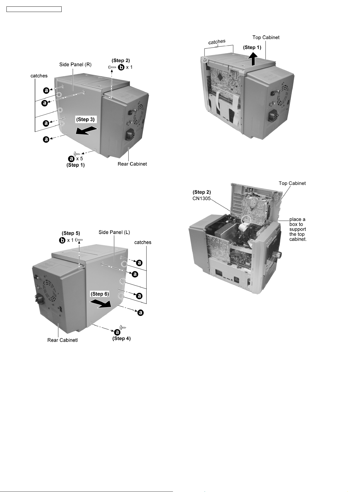
12.2. Disassembly of Side Panel L &
R
Step 1 : Lift up the top cabinet as arrow shown (Be careful of
the catches).
Step 1 : Remove 5 screws from the side panel (R).
Step 2 : Remove 1 screws from the corner of the side panel
(R).
Step 3 : Remove the side panel as arrow shown (Be careful of
the catches).
Step 4 : Remove 5 screws from the side panel (L).
Step 5 : Remove 1 screws from the corner of the side panel (L).
Step 6 : Remove the side panel as arrow shown (Be careful of
the catches).
Step 2 : Place the top cabinet as shown and detach the
connector CN1305.
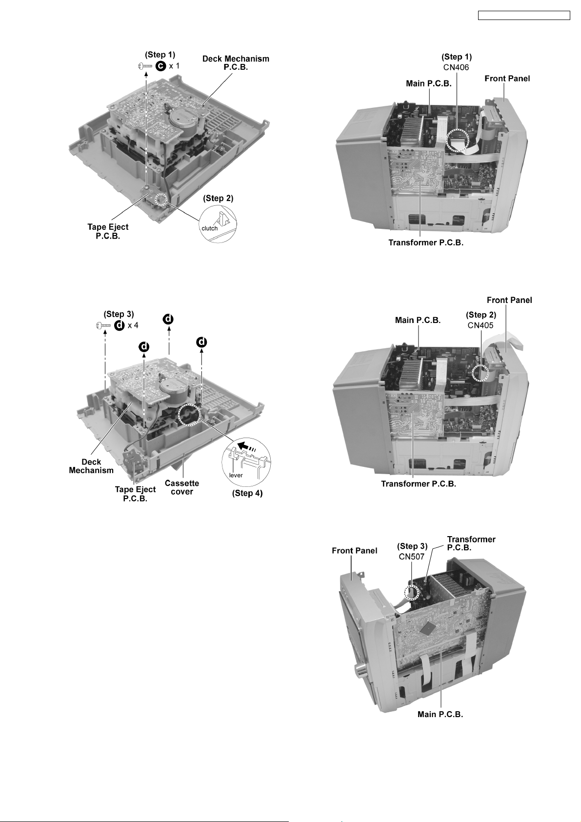
12.4. Disassembly of Deck
Mechanism P.C.B. and Tape
Eject P.C.B.
· Follow the (Step 1) - (Step 6) of item 12.2.
· Follow the (Step 1) - (Step 2) of item 12.3.
12.3. Disassembly of Top Cabinet
· Follow the (Step 1) - (Step 6) of item 12.2.
20
SA-PM71SDGN / SA-PM71SDGT
Step 1 : Remove 1 screw.
Step 2 : Release the clutch and remove the Tape Eject P.C.B..
Step 3 : Remove 4 screws.
Step 4 : Push the lever as arrow shown to remove the Deck
Mechanism.
Step 1 : Detach the connector CN406.
Step 2 : Detach the connector CN405.
12.5. Disassembly of Front Panel
· Follow the (Step 1) - (Step 6) of item 12.2.
· Follow the (Step 1) - (Step 2) of item 12.3.
Step 2 : Detach the connector CN507.
21
SA-PM71SDGN / SA-PM71SDGT
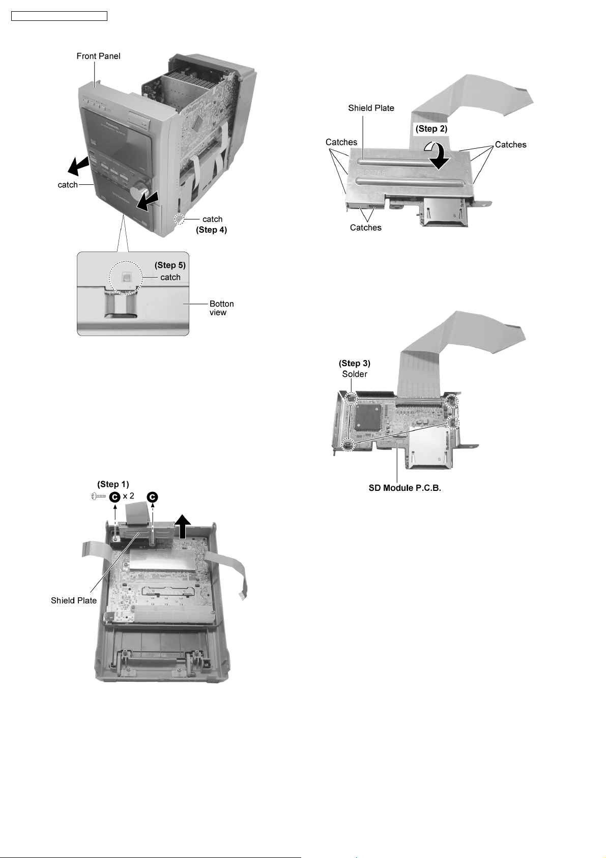
Step 2 : Remove shield plate. (Be careful of the catches)
Step 4 : Release 2 catches.
Step 5 : Release the catch at the bottom cabinet and remove
the front panel as arrow shown.
12.6. Disassembly of SD Module
P.C.B.
· Follow the (Step 1) - (Step 6) of item 12.2.
· Follow the (Step 1) - (Step 2) of item 12.3.
· Follow the (Step 1) - (Step 5) of item 12.5.
Step 3 : Unsolder 4 point to remove SD Module P.C.B..
12.7. Disassembly of Panel P.C.B.
· Follow the (Step 1) - (Step 6) of item 12.2.
· Follow the (Step 1) - (Step 2) of item 12.3.
· Follow the (Step 1) - (Step 5) of item 12.5.
· Follow the (Step 1) of item 12.6.
Step 1 : Remove 2 screws to remove the SD Module P.C.B.
with shield plate as arrow shown.
22
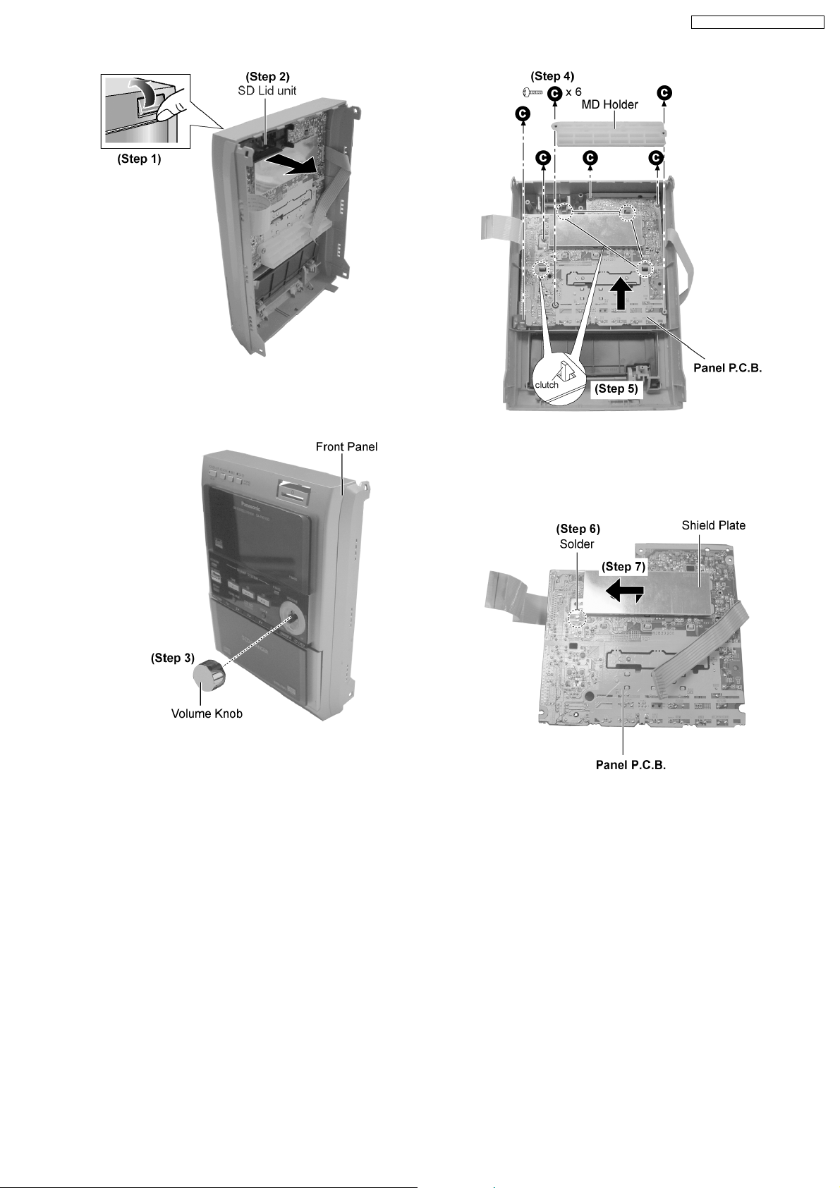
Step 1 : Flip open the SD cover as arrow shown.
Step 2 : Remove the SD Lid unit as arrow shown.
SA-PM71SDGN / SA-PM71SDGT
Step 3 : Remove the volume knob.
Step 4 : Remove 6 screws and MD Holder.
Step 5 : Release 4 clutches and remove the Panel P.C.B. as
arrow shown.
Step 6 : Unsolder the shield plate.
Step 7 : Remove the shield plate as arrow shown.
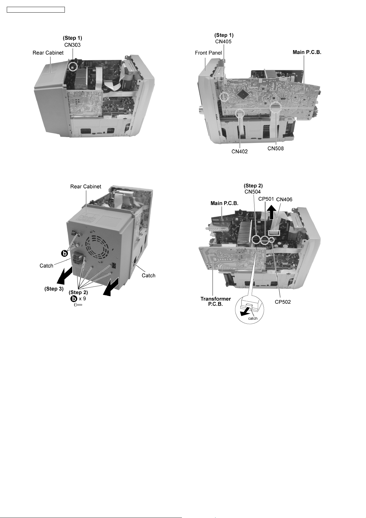
12.8. Disassembly of Rear Cabinet
· Follow the (Step 1) - (Step 6) of item 12.2.
· Follow the (Step 1) - (Step 2) of item 12.3.
23
SA-PM71SDGN / SA-PM71SDGT
Step 1 : Detach the connector CN303.
Step 2 : Remove 9 screws altogether.
Step 3 : Remove the rear cabinet as arrows shown (Be careful
of the catches).
12.9. Disassembly of Main P.C.B.
· Follow the (Step 1) - (Step 6) of item 12.2.
· Follow the (Step 1) - (Step 2) of item 12.3.
· Follow the (Step 1) - (Step 3) of item 12.8.
Step 1 : Detach the connector CN405 , CN402 and CN508.
Step 2 : Detach the connectors CN406.
Step 3 : Releas e the catch as arrow shown and detach the
connector CN504, CP501 and CP502 and pull out the Main
P.C.B. as arrow shown.
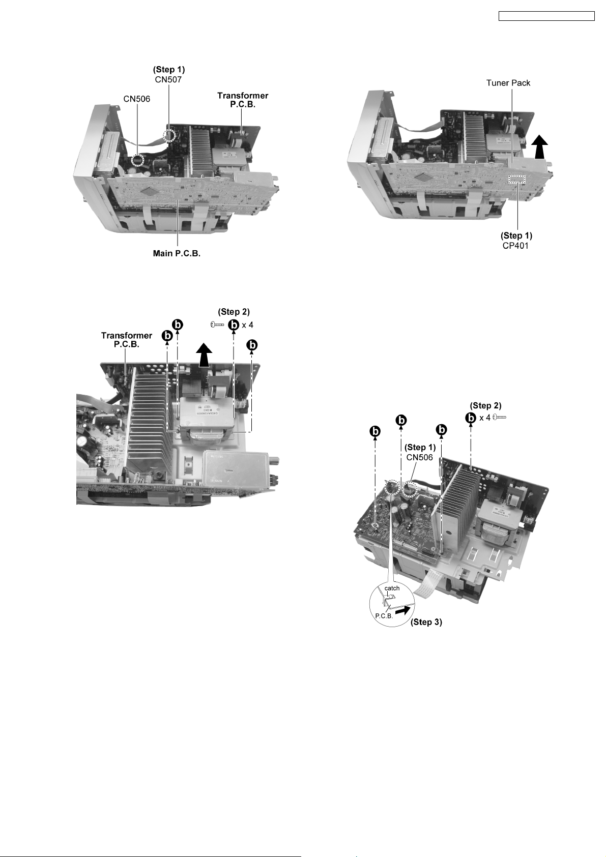
12.10. Disassembly of Transformer
P.C.B.
· Follow the (Step 1) - (Step 6) of item 12.2.
· Follow the (Step 1) - (Step 2) of item 12.3.
· Follow the (Step 1) - (Step 3) of item 12.8.
24
SA-PM71SDGN / SA-PM71SDGT
Step 1 : Detach the connectors CN506 and CN507.
Step 2 : Remove 4 screws and pull out the Transformer P.C.B.
as arrow shown.
12.11. Disassembly of Tuner Pack
Step 1 : Detach the connector CP401 and remove the tuner
pack as arrow shown.
12.12. Disassembly of Power P.C.B.
· Follow the (Step 1) - (Step 6) of item 12.2.
· Follow the (Step 1) - (Step 2) of item 12.3.
· Follow the (Step 1) - (Step 5) of item 12.5.
· Follow the (Step 1) - (Step 3) of item 12.8.
· Follow the (Step 1) - (Step 3) of item 12.9.
· Follow the (Step 1) - (Step 6) of item 12.2.
· Follow the (Step 1) - (Step 2) of item 12.3.
· Follow the (Step 1) - (Step 3) of item 12.8.
Step 1 : Detach the connector CN506.
Step 2 : Remove 4 screws.
Step 3 : Remove the Power P.C.B. (Be careful of the catch)
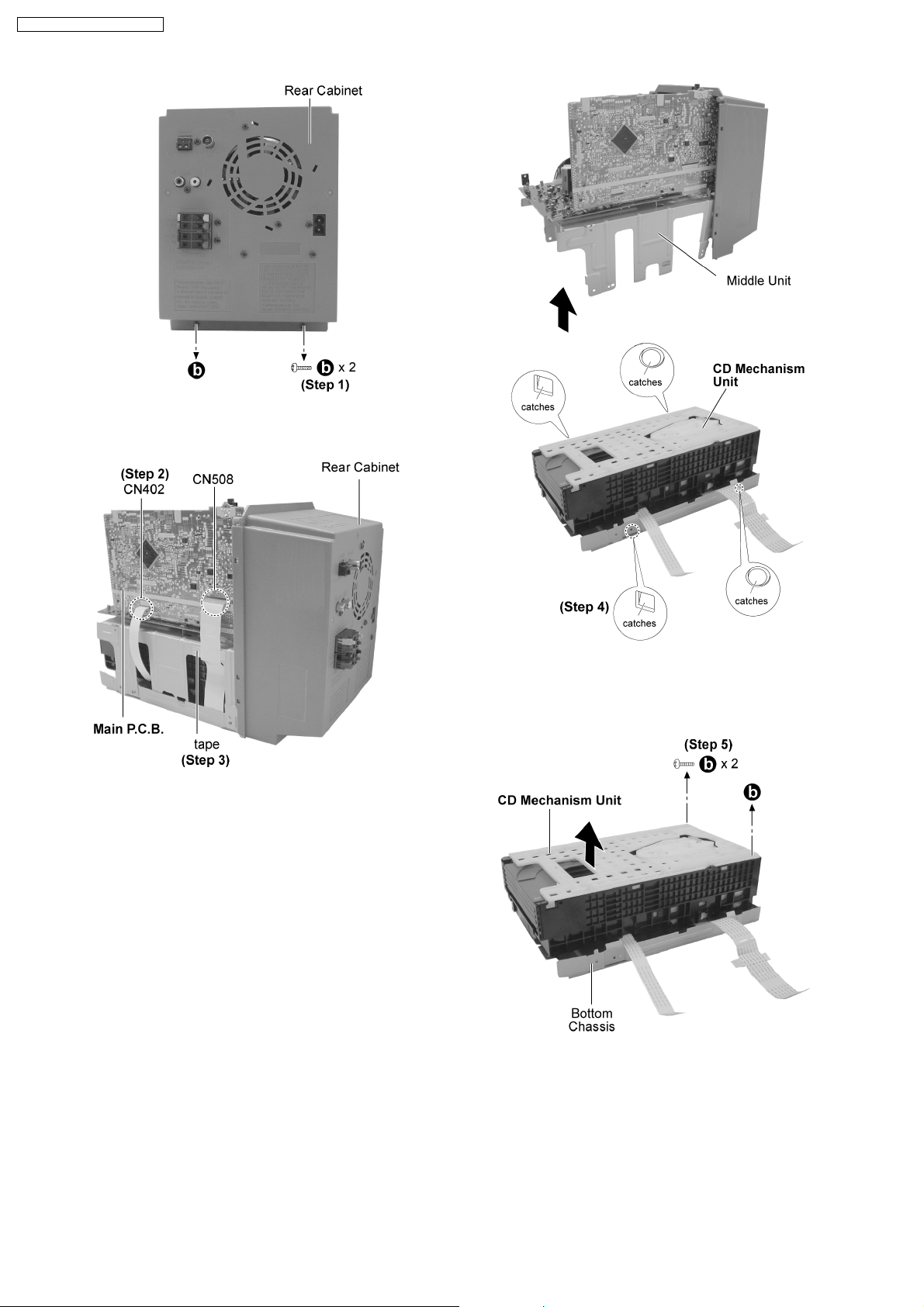
12.13. Disassembly of CR16
Mechanism
· Follow the (Step 1) - (Step 6) of item 12.2.
· Follow the (Step 1) - (Step 2) of item 12.3.
· Follow the (Step 1) - (Step 5) of item 12.5.
25
SA-PM71SDGN / SA-PM71SDGT
Step 1 : Remove 2 screws.
Step 2 : Detach the connectors CN402 and CN508.
Step 3 : Remove the tape which used to secure the FFC
connectors.
Step 4 : Release the catches and remove the middle unit as
arrow shown.
Step 5 : Remove 2 screws and remove the CD Mechanism Unit
from the bottom chassis as arrow shown.
12.14. Replacement of CD Lid and
Inner CD Lid
· Follow the (Step 1) - (Step 6) of item 12.2.
· Follow the (Step 1) - (Step 2) of item 12.3.
26
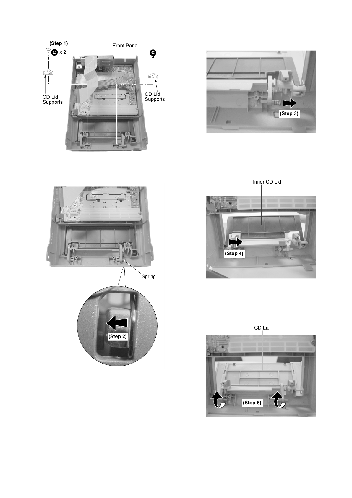
· Follow the (Step 1) - (Step 5) of item 12.5.
Step 1 : Remove 2 screws 2 CD Lid supports.
SA-PM71SDGN / SA-PM71SDGT
Step 3 : Remove the spring as arrow shown.
Step 2 : Release the spring hook as arrow shown.
Step 4 : Remove the Inner CD Lid as arrow shown.
Step 5 : Remove the CD lid as arrow shown.
27
SA-PM71SDGN / SA-PM71SDGT
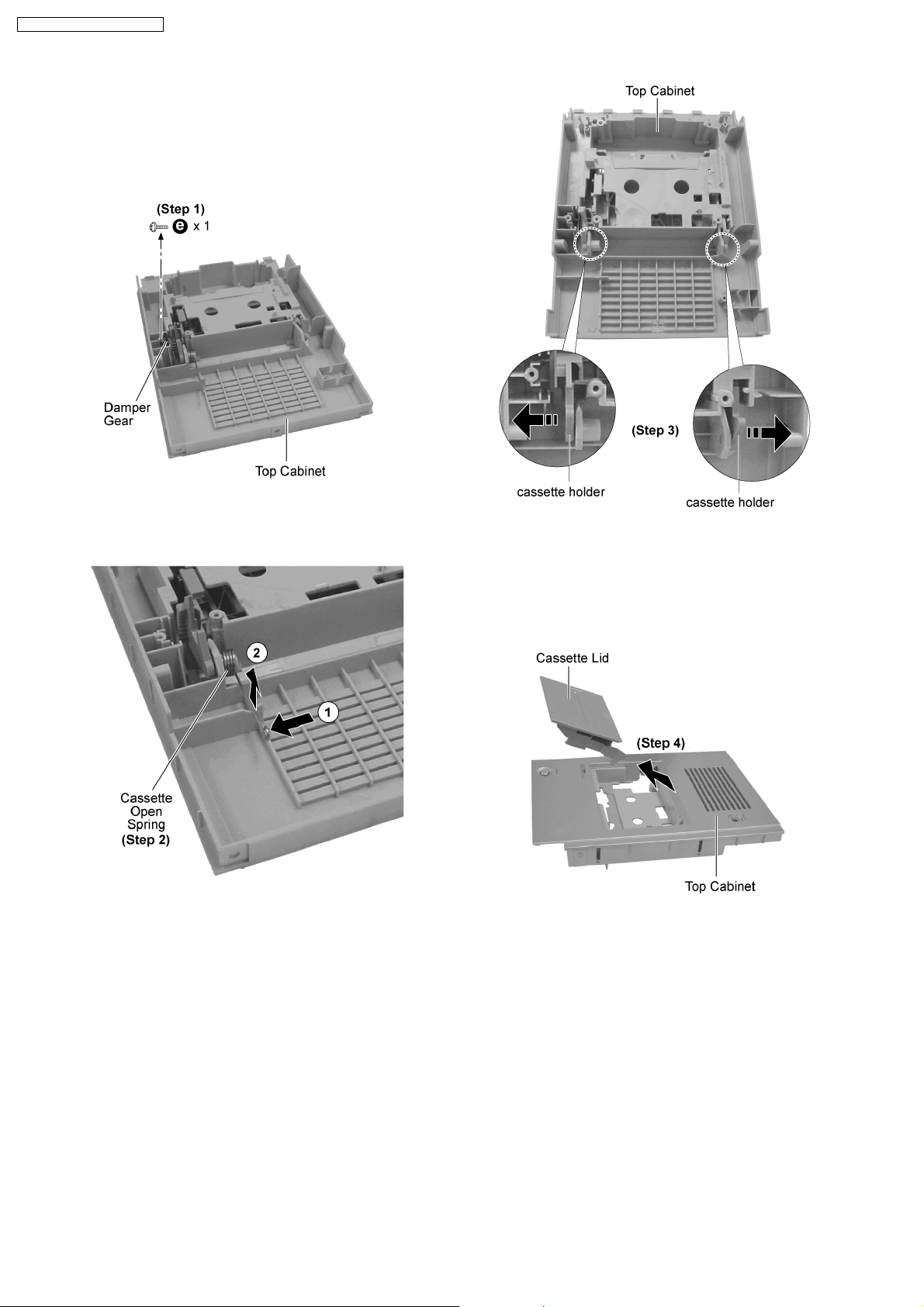
12.15. Replacement of Cassette Lid
· Follow the (Step 1) - (Step 6) of item 12.2.
· Follow the (Step 1) - (Step 2) of item 12.3.
· Follow the (Step 1) - (Step 4) of item 12.4.
Step 1 : Remove 1 screw and the damper gear.
Step 2 : Remove the cassette open spring as arrows shown in
order.
Step 3 : Pull both sides cassette holders to the direction of the
arrows shown.
Step 4 : Remove the cassette lid as arrow shown.
12.16. Replacement of the Power IC
and Transistors
· Follow the (Step 1) - (Step 6) of item 12.2.
· Follow the (Step 1) - (Step 2) of item 12.3.
· Follow the (Step 1) - (Step 5) of item 12.5.
· Follow the (Step 1) - (Step 3) of item 12.8.
· Follow the (Step 1) - (Step 3) of item 12.9.
· Follow the (Step 1) - (Step 3) of item 12.12.
28
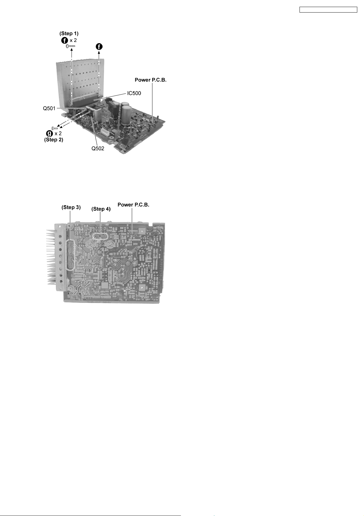
Step 1 : Remove 2 screws.
Step 2 : Remove 2 screws.
SA-PM71SDGN / SA-PM71SDGT
Step 3 : Unsolder the Power IC500.
Step 4 : Unsolder the Transistor Q501 and Q502.
29
SA-PM71SDGN / SA-PM71SDGT
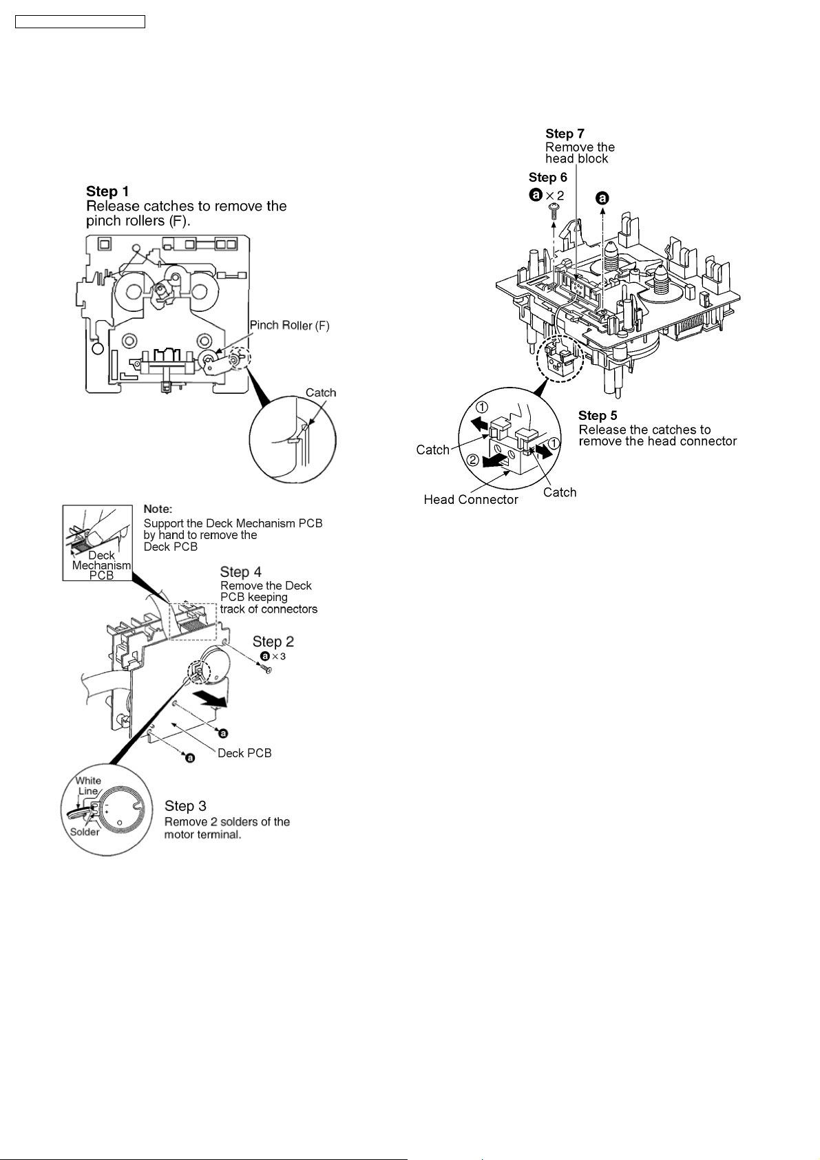
12.17. Procedure for Replacing Pinch Roller and Head Block (Deck
Mechanism Unit)
· Follow the (Step 1) - (Step 6) of Item 12.2.
· Follow the (Step 1) - (Step 2) of Item 12.3.
· Follow the (Step 1) - (Step 4) of Item 12.4.
12.18. Procedure for Replacing Motor, Capstan Belt A, Capstan Belt B, and
Winding Belt (Deck Mechanism Unit)
· Follow the (Step 1) - (Step 6) of Item 12.2.
· Follow the (Step 1) - (Step 2) of Item 12.3.
· Follow the (Step 1) - (Step 4) of Item 12.4.
· Follow the (Step 1) - (Step 4) of Item 12.17.
30
 Loading...