

Page 1
A
CD Stereo System
SA-PM71SDE
SA-PM71SDEB
SA-PM71SDEG
Colour
(S)... Silver Type
ORDER NO. MD0504157C2
Specification
n Amplifier Section
RMS output power, both channels driven
10%, Total harmonic distortion
1 kHz (Low channel) 40 W per channel
(6 Ω)
8 kHz (High channel) 40 W per channel
(6 Ω)
Total Bi-Amp power 80 W per channel
Output Impedance
Headphone 16Ω -32Ω
n FM Tuner Section
Frequency range 87.50 MHz to 108.00 MHz
(50 kHz steps)
Sensitivity 1.50 µV (IHF)
S/N 26dB 1.70 µV
ntenna terminals 75 Ω (unbalanced)
Preset stations 15
n AM Tuner Section
Frequency range 522 kHz to 1629 kHz (Default)
(9 kHz steps)
520 kHz to 1630 kHz
(10 kHz steps)
Sensitivity S/N 20 dB at 999 kHz 560 µV/m
Preset stations 15
n Cassette Deck Section
Track system 4 track, 2 channel
Heads
Record/playback Solid permalloy head
Erasure Double gap ferrite head
Motor DC servo motor
Recording system AC bias 100 kHz
Erase system AC erase 100 kHz
Tape speed 4.8cm/s(1-7/8ips)
Overall frequency response (+3 dB, -6 dB) at DECK OUT
Normal 35 Hz to 14 kHz
Wow and flutter 0.10% (WRMS)
Fast forward and rewind time Approx. 120 seconds with C-60
cassette tape
n CD Section
Disc CD,MP3,WMA,CD-R/RW,
HighMat
8cm (3”) / 12 cm (5”)
Sampling frequency
CD 44.1 kHz
MP3/WMA 32 kHz, 44.1 kHz, 48 kHz
Bit rate
MP3 32 kbps to 320 kbps
WMA 40 kbps to 192 kbps
Decoding 16 bit linear
Pickup
Beam source Semiconductor laser
Wavelength 780 nm
Number of channels Stereo
Frequency response 20 Hz to 20 kHz (+1dB, -2 dB)
© 2005 Matsushita Electric Industrial Co. Ltd.. All
rights reserved. Unauthorized copying and
distribution is a violation of law.
Page 2
SA-PM71SDE / SA-PM71SDEB / SA-PM71SDEG
Wow and flutter Below measurable limit
Digital filter 8fs
D/A converter MASH (1 bit DAC)
n SD Section
Sampling frequency 32 kHz (LP), 44.1 kHz (SP,XP)
Coding system
SD Audio Playback AAC, MP3, W MA
SD Audio Record AAC
Number of channels 2 channel (stereo)
n Other
CD → SD Recording speed Maximum 4 times (LP)
n General
Power supply AC 230 V, 50 Hz (For E/EG)
AC 230 - 240 V, 50 Hz (For EB)
Power consumption 130 W
Dimensions (W x H x D) 175 mm x 249.5 mm x 379.6 mm
(6 29/32 x 9 27/32” x 14 31/32”)
Mass 5.8 kg (12.8 Ibs)
Power consumption in standby
mode
Notes :
1. Specifications are subject to change without notices. Mass and
dimensions are approximate.
2. Total harmonic distortion is measured by the digital spectrum
analyzer.
n System : SC-PM71SDE-S
n System : SC-PM71SDEBS
n System : SC-PM71SDEGS
Music center: SA-PM71SDE-S
Speaker: SB-PM71P-M
Music center: SA-PM71SDEBS
Speaker: SB-PM71P-M
Music center: SA-PM71SDEGS
Speaker: SB-PM71P-M
0.5 W
CONTENTS
Page Page
1 Safety Precautions
1.1. GENERAL GUIDELINES
2 Caution for AC Mains Lead
3 Before Repair and Adjustment
4 Protection Circuitry
5 Handling the Lead-free Solder
5.1. About lead free solder (PbF)
6 Precaution of Laser Diode
7 Handling Precautions For Traverse Deck
8 Accessories
9 Operation Procedures
9.1. Main Unit
9.2. Remote Control
10 Information on Disc & MP3
11 SD Card Information
12 About HighMAT
12.1. What 痴 HighMAT?
12.2. Why take advantage of HighMAT?
12.3. Benefits of HighMAT?
13 Assembling and Disassembling
13.1. Disassembly flow chart
13.2. Disassembly of Side Panel L & R
13.3. Disassembly of Top Cabinet
13.4. Disassembly of Deck Mechanism P.C.B. and Tape Eject
P.C.B.
13.5. Disassembly of Front Panel
13.6. Disassembly of SD Module P.C.B.
13.7. Disassembly of Panel P.C.B.
13.8. Disassembly of Rear Cabinet
4
4
5
6
6
6
6
7
8
9
10
10
11
12
14
16
16
16
17
20
20
21
21
21
22
23
23
24
13.9. Disassembly of Main P.C.B.
13.10. Disassembly of Transforme r P.C.B.
13.11. Disassembly of Tuner Pack
13.12. Disassembly of Power P.C.B.
13.13. Disassembly of CR16 Mechanism
13.14. Replacement of CD Lid and Inner CD Lid
13.15. Replacement of Cassette Lid
13.16. Replacement of the Power IC and Transistors
13.17. Procedure for Replacing Pinch Roller and Head Block
(Deck Mechanism Unit)
13.18. Procedure for Replacing Motor, Capstan Belt A, Capstan
Belt B, and Winding Belt (Deck Mechanism Unit)
13.19. Procedure for Replacing Parts on Deck Mechanism PCB
13.20. Disassembly of CR16 Mechanism
13.21. Replacement of optical pickup unit (CD mechanism)
13.22. Replacement of a traverse gear A and a traverse gear B
13.23. Procedure for removing CD loading mechanism
13.24. CR16 mechanism disassembly procedure
13.25. CR16 MECHANISM ASSEMBLY PROCEDURE
13.26. Disassembly of traverse mechanism
13.27. Handling of cassette tape jam
14 Service Positions
14.1. Checking procedure
14.2. Checking the major P.C.B
15 Self-Diagnostic Display Function
15.1. Entering into Self-Diagnostic Mode
15.2. Error Code Table
25
25
26
26
26
27
29
29
31
31
33
33
34
36
37
37
43
56
57
58
58
58
59
59
60
2
Page 3

SA-PM71SDE / SA-PM71SDEB / SA-PM71SDEG
15.3. Changer Reliability Test Mode 61
16 Procedure for Checking Operation of Individual Parts of Deck
Mechanism Unit
16.1. Operation Check with Cassette Tape
16.2. Operation Check without Cassette Tape
17 Measurement And Adjustments
17.1. Cassette Deck Section
18 Voltage Measurement and Waveform Chart
18.1. Voltage Measurement
18.2. Waveform Chart
19 Block Diagram
19.1. CD SERVO Block
19.2. MAIN Block
20 Notes of Schematic Diagram
21 Schematic Diagram
21.1. CD SERVO CIRCUIT
21.2. SD MODULE CIRCUIT
21.3. MAIN CIRCUIT
21.4. PANEL CIRCUIT and TRANSFORMER CIRCUIT
21.5. POWER CIRCUIT
62
62
62
64
64
66
66
72
74
74
76
83
84
84
86
91
96
98
21.6. DECK CIRCUIT, DECK MECHANISM CIRCUIT and TAPE
EJECT CIRCUIT
21.7. CD LOADING CIRCUIT
22 Printed Circuit Board
100
102
103
22.1. CD SERVO P.C.B
22.2. SD MODULE P.C.B
22.3. MAIN P.C.B
22.4. PANEL P.C.B
22.5. TRANSFORMER P.C.B
22.6. POWER P.C.B
22.7. DECK P.C.B and TAPE EJECT P.C.B
22.8. DECK MECHANISM P.C.B and CD LOADING P.C.B
23 Wiring Connection Diagram
24 Illustration of IC 痴, Transistors and Diodes
25 Terminal Function of ICエs
25.1. IC807 (MN103SF77RXW) IC SD Audio Drive Controller
25.2. IC703 (BA5948FPE2) IC 4CH Drive
26 Troubleshooting Flowchart (CD Section Circuit)
27 Troubleshooting Flowchart (SD Card Section Circuit)
28 Parts Location and Replacement Parts List
28.1. Deck Mechanism
28.2. CD LOading Mechanisms
28.3. Cabinet Part List
28.4. Electrical Part List
28.5. Packaging Materials & Accessories Parts List
28.6. Packaging
103
105
106
108
109
110
111
112
113
115
116
116
117
118
120
122
123
125
130
134
145
145
3
Page 4
SA-PM71SDE / SA-PM71SDEB / SA-PM71SDEG
1 Safety Precautions
1.1. GENERAL GUIDELINES
1. When servicing, observe the original lead dress. If a short circuit is found, replace all parts which have been overheated or
damaged by the short circuit.
2. After servicing, ensure that all the protective devices such as insulation barriers, insulation papers shields are properly installed.
3. After servicing, check for leakage current checks to prevent from being exposed to shock hazards.
1.1.1. LEAKAGE CURRENT COLD CHECK
1. Unplug the AC cord and connect a jumper between the two prongs on the plug.
2. Using an ohmmeter measure the resistance value, between the jumpered AC plug and each expose d metallic cabinet part on
the equipment such as screwheads, connectors, control shafts, etc. When the exposed metallic part has a return path to the
chassis, the reading should be between 1MΩand 5.2Ω.
When the exposed metal does not have a return path to the chassis, the reading must be
.
Fig. 1
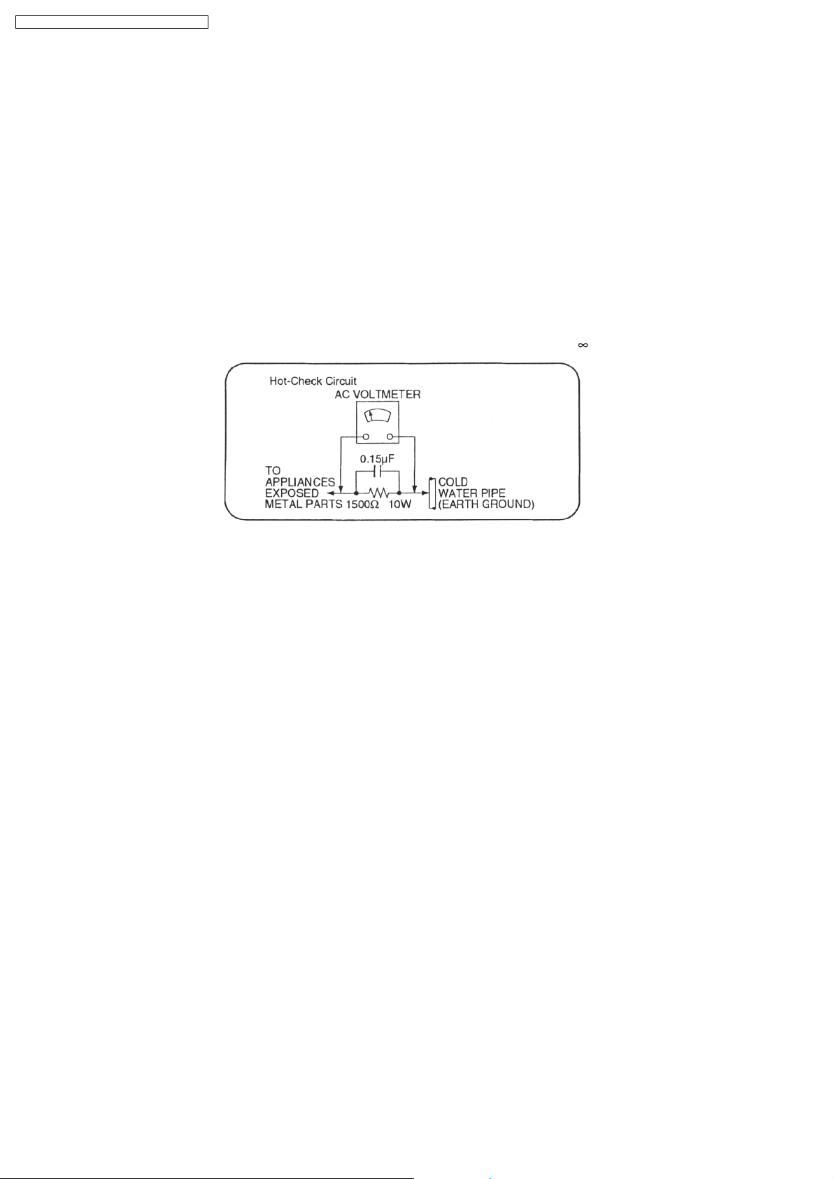
1.1.2. LEAKAGE CURRENT HOT CHECK (See Figure 1.)
1. Plug the AC cord directly into the AC outlet. Do not use an isolatio n transfo rmer for this check.
2. Connect a 1.5kΩ, 10 watts resistor, in parallel with a 0.15µF capacitors, between each exposed metallic part on the set and a
good earth ground such as a water pipe, as shown in Figure 1.
3. Use an AC voltmeter, with 1000 ohms/volt or more sensitivity, to measure the potential across the resistor.
4. Check each exposed metallic part, and measure the voltage at each point.
5. Reverse the AC plug in the AC outlet and repeat each of the above measurements.
6. The potential at any point should not exceed 0.75 volts RMS. A leakage current tester (Simpson Model 229 or equivalent) may
be used to make the hot checks, leakage current must not exceed 1/2 milliamp. should the measurement is outside of the limits
specified, there is a possibility of a shock hazard, and the equipment should be repaired and re-checked before it is returned
to the customer.
4
Page 5
2 Caution for AC Mains Lead
SA-PM71SDE / SA-PM71SDEB / SA-PM71SDEG
5
Page 6

SA-PM71SDE / SA-PM71SDEB / SA-PM71SDEG
3 Before Repair and Adjustment
Disconnect AC power, discharge Power Supply Capacitors C448, C449, C452, C455, C456, C506, C507, C508 & C584 through
a10Ω, 1W resistor to ground.
DO NOT SHORT-CIRCUIT DIRECTLY (with a screwdriver blade, for instance), as this may destroy solid state devices.
After repairs are completed, restore power gradually using a variac, to avoid overcurrent.
· Current consumption at AC 230V, 50 Hz in NO SIGNAL mode should be ~300 mA. (For E/EG)
· Current consumption at AC 230V-2 40V, 50 Hz in NO SIGNAL mode should be ~300 mA. (For EB)
4 Protection Circuitry
The protection circuitry may have operated if either of the following conditions are noticed:
· No sound is heard when the power is turned on.
· Sound stops during a performance.
The function of this circuitry is to prevent circuitry damage if, for example, the positive and negative speaker connection wires are
"shorted", or if speaker systems with an impedance less than the indicated rated impedance of the amplifier are used.
If this occurs, follow the procedure outline s below:
1. Turn off the power.
2. Determine the cause of the problem and correct it.
3. Turn on the power once again after one minute.
Note:
When the protection circuitry functions, the unit will not operate unless the power is first turned off and then on again.
5 Handling the Lead-free Solder
5.1. About lead free solder (PbF)
Distinction of PbF P.C.B.:
P.C.B.s (manufactured) using lead free solder will have a PbF stamp on the P.C.B.
Caution:
· Pb free solder has a higher melting point than standard solder; Typically the melting point is 50 - 70°F (30 - 40°C) higher. Please
use a high temperature soldering iron. In case of soldering iron with temperature control, please set it to 700 ± 20°F (370 ±
10°C).
· Pb free solder will tend to splash when heated too high (about 1100°F/600°C).
· W hen soldering or unsoldering, please completely remove all of the solder on the pins or solder area, and be sure to heat the
soldering points with the Pb free solder until it melts enough.
6
Page 7
SA-PM71SDE / SA-PM71SDEB / SA-PM71SDEG
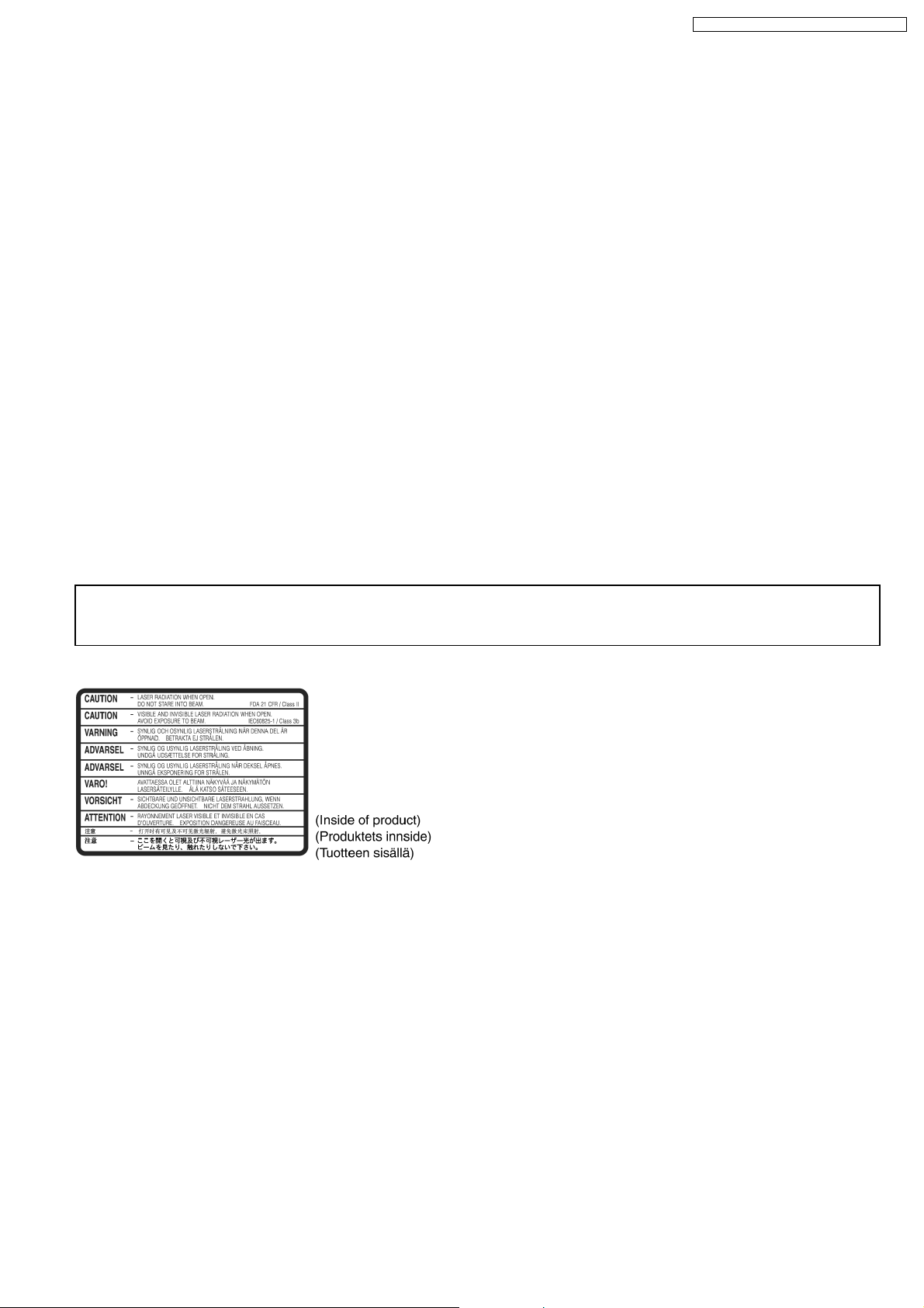
6 Precaution of Laser Diode
Caution :
This product utilizes a laser diode with the unit turned "ON", invisible laser radiation is emitted from the pick up lens.
Wavelength : 780 nm
Maximum output radiation power from pick up : 100 µW/VDE
Laser radiation from pick up unit is safety level, but be sure the followings:
1. Do not disassemble the optical pick up unit, since radiation from exposed laser diode is dangerous.
2. Do not adjust the variable resistor on the pick up unit. It was already adjusted.
3. Do not look at the focus lens using optical instruments.
4. Recommend not to look at pick up lens for a long time.
ACHTUNG :
Dieses Produkt enthält eine Laserdiode. Im eingeschalteten Zustand wird unsichtbare Laserstrahlun g von der Lasereinheit
abgestrahlt.
Wellenlänge : 780nm
Maximale Strahlungsleistung der Lasereinheit :100µW/VDE
Die Strahlung an der Lasereinheit ist ungefährlich, wenn folgende Punkte beachtet werden:
1. Die Lasereinheit nicht zerlegen, da die Strahlung an der freigelegten Laserdiode gefährlich ist.
2. Den werkseitig justierten Einstellregler der Lasereinhit nicht verstellen.
3. Nicht mit optischen Instrumenten in die Fokussierlinse blicken.
4. Nicht über längere Zeit in die Fokussierlinse blicken.
ADVARSEL :
I dette a apparat anvendes laser.
CAUTION!
THIS PRODUCT UTILIZES A LASER.
USE OF CONTROLS OR ADJUSTMENTS OR PERFORMANCE OF PROCEDURES OTHER THAN THOSE SPECIFIED HEREIN MAY RESULT
IN HAZARDOUS RADIATION EXPOSURE.
n Use of Caution Labels
7
Page 8
SA-PM71SDE / SA-PM71SDEB / SA-PM71SDEG
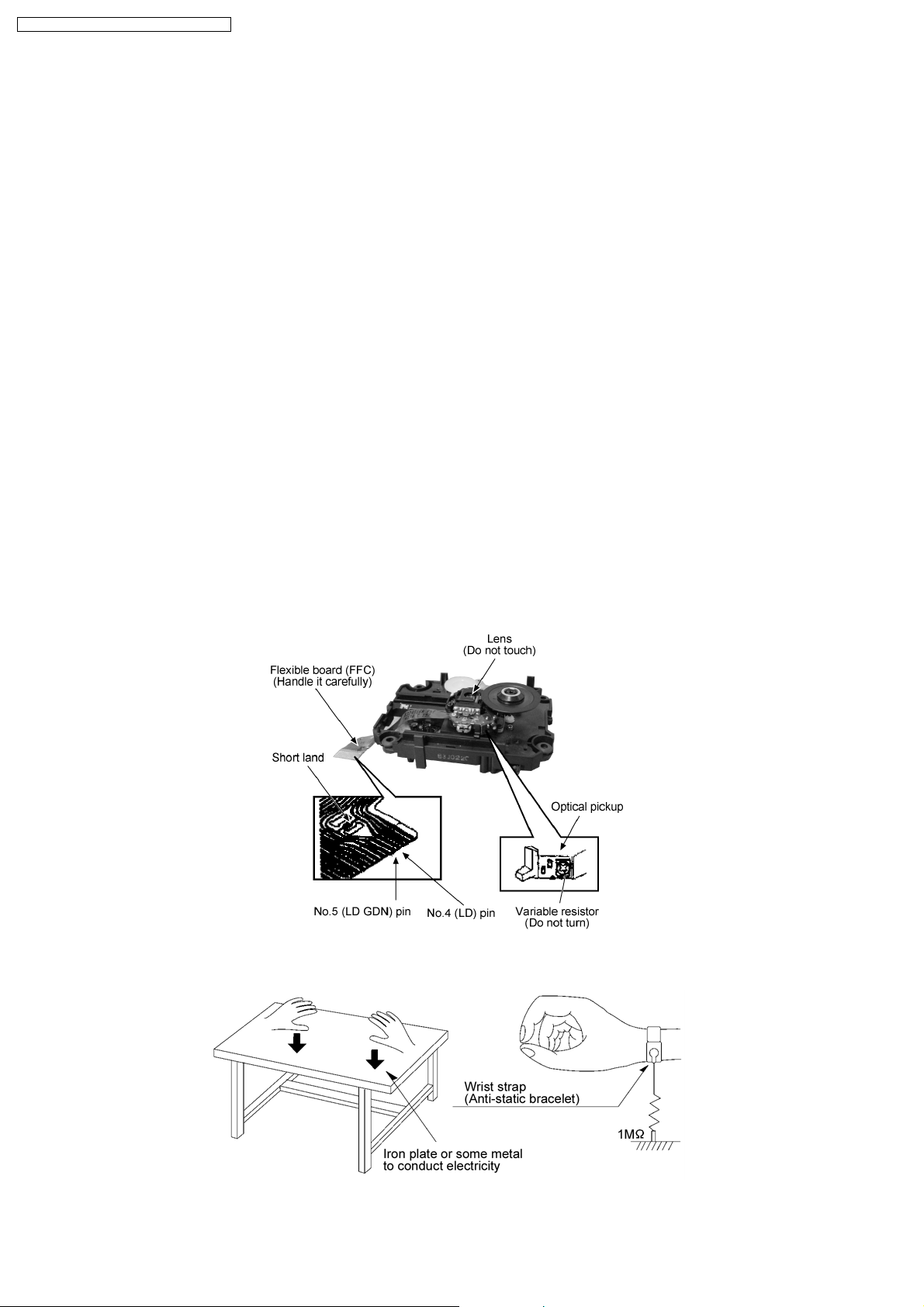
7 Handling Precautions For Traverse Deck
The laser diode in the traverse deck (optical pickup) may break down due to potential difference caused by static electricity of
clothes or human body. So, be careful of electrostatic breakdown during repair of the traverse deck (optical pickup).
· Handling of traverse deck (optical pickup)
1. Do not subject the traverse deck (optical pickup) to static electricity as it is extremely sensitive to electrical shock.
2. To prevent the breakdown of the laser diode, an antistatic shorting pin is inserted into the flexible board (FFC board).
3. Take care not to apply excessive stress to the flexible board (FFC board). When removing or connecting the short pin, finish
the job in as short time as possible. (Fig 7.1)
4. Do not turn the variable resistor (laser power adjustment). It has already been adjusted.
· Grounding for electrostatic breakdown prevention
1. Work table grounding. (Fig 7.2)
Use the anti-static wrist strap to discharge the static electricity from your body.
2. Work table grounding. (Fig 7.2)
Put a conductive material (sheet) or steel sheet on the area where the traverse deck (optical pickup) is place, and ground
the sheet.
Caution:
The static electricity of your clothes will not be grounded through the wrist strap. So, take care not to let your clothes touch the
traverse deck (optical pickup).
Caution when replacing the Traverse Deck
The traverse deck has a short point shorted with solder to protect the laser diode against electrostatics breakdown. Be sure to
remove the solder from the short point before making connections.
(Fig 7.1)
(Figs 7.2)
8
Page 9
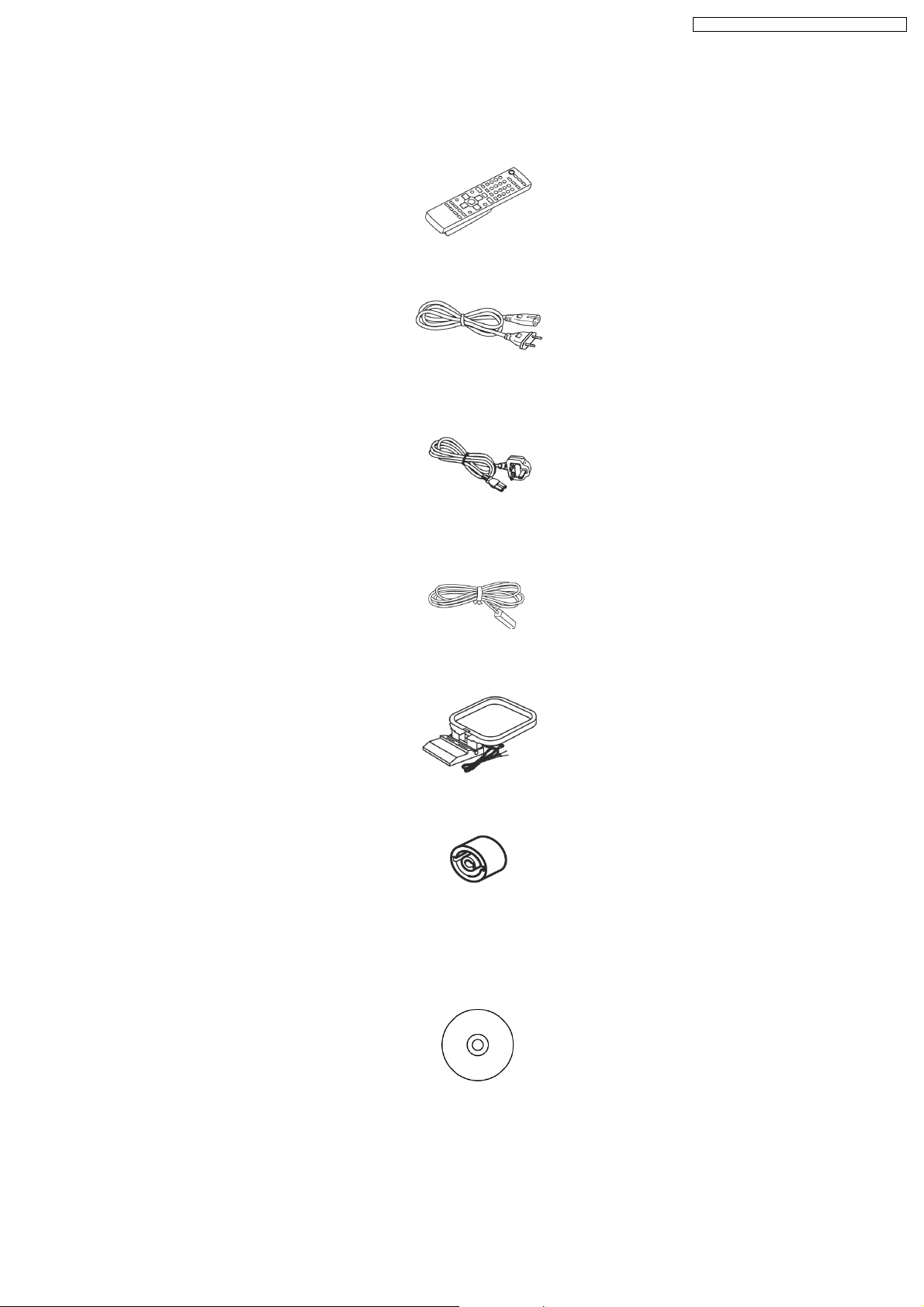
8 Accessories
Note : Refer to Packing Materials & Accessories Parts List (Section 28.5) for the part number.
Remote Control
AC cord (For E/EG
only)
SA-PM71SDE / SA-PM71SDEB / SA-PM71SDEG
AC cord (For EB
only)
FM indoor antenna
AM loop antenna
Antenna
plug
adaptor
(For EB
only)
CD ROM
9
Page 10
SA-PM71SDE / SA-PM71SDEB / SA-PM71SDEG
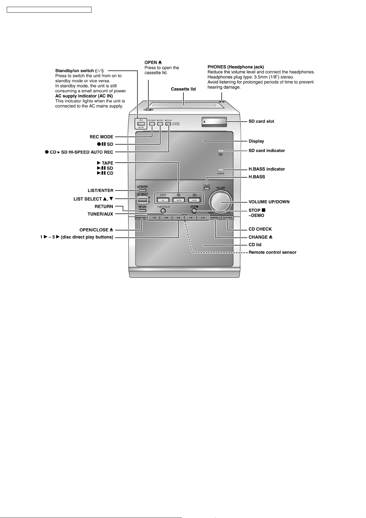
9 Operation Procedures
9.1. Main Unit
10
Page 11
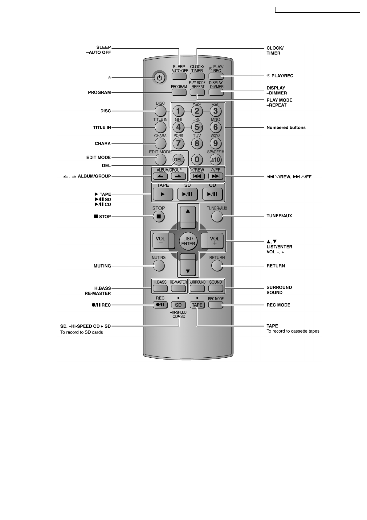
9.2. Remote Control
SA-PM71SDE / SA-PM71SDEB / SA-PM71SDEG
11
Page 12
SA-PM71SDE / SA-PM71SDEB / SA-PM71SDEG
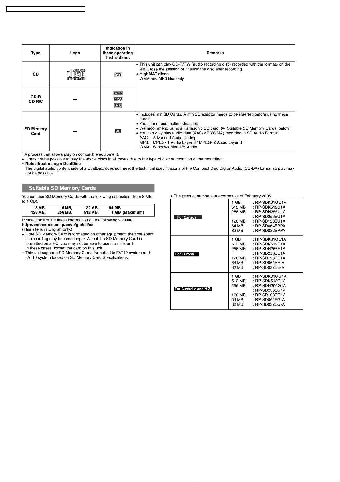
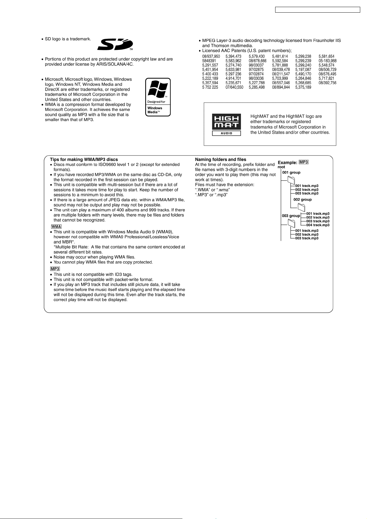
10 Information on Disc & MP3
12
Page 13
SA-PM71SDE / SA-PM71SDEB / SA-PM71SDEG
13
Page 14
SA-PM71SDE / SA-PM71SDEB / SA-PM71SDEG
11 SD Card Information
A New Lifestyle is Evolving with the SD Memory Card
The SD Memory Card is at the heart of many Panasonic products. It´s a high-capacity, high-speed storage medium for the digital
age. Incredibly small yet durable, the SD Memory Card is about the size of a postage stamp. It can store all kinds of digital content,
like video, still images, music and more! So you can transfer data easily between products with an SD Card slot.
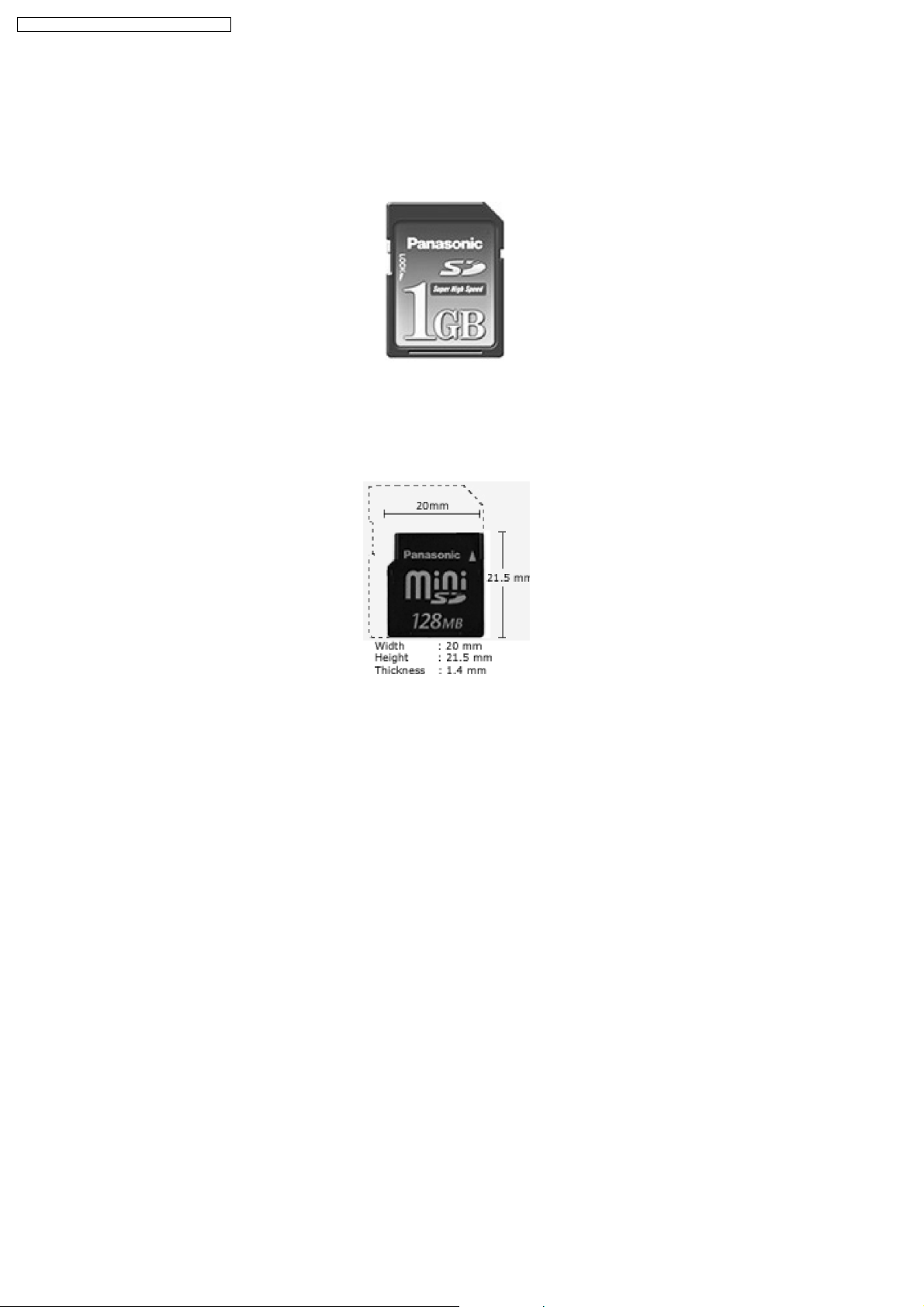
The miniSD card
The miniSD card was developed to meet industry deman ds for a memory card small enough for today’s compact mobile phones.
It is about 40% smaller than a Panasonic SD Memory Card, but offers all the benefits-including copyright protection. Each miniSD
card comes with an adapter that makes the miniSD card compatible with standard SD-enabled products.
Ideal for MPEG2 Video Recording
The increasing data volume and expand ing range of digital contents require high data reading and writing speeds. Panasonic SD
Memory Cards, 256MB
1
and higher, achieve the data writing speed fast enough to record MPEG2 video in fine mode.
Compact & Slim
The SD Memory Card measures a mere 0.94" x 1.26" x .08" (24mm x 32mm x 2.1mm). Its slim, compact design promotes easy
handling-an important factor for moving between differe nt SD-compatible products. Our SD Memory Cards are small enough to be
used in select mobile phones and PDAs, as well as many other compact or multi-functional products.
Large Capacity
SD Memory Cards are currently available in several capacities up to 1GB
2
. Be on the lookout in the near future for 2GB2and 4GB
cards. This kind of large capacity is essential for use with various digital content types, especially high-quality MPEG2 video.
Fast Access
Providing quick response and effortless handling of digital content, SD Memory Cards 256MB
1
and higher can write data fast
enough to record high-quality MPEG2 video in fine mode.
Copyright Protection
The copyright protection technology used for the SD Memory Card, Content Protection for Recordable Media (CPRM), is the key
to enabling a new distribution system for music and other commercial media. CPRM assures a high level of protection against
illegal copying and was developed by 4C (The digital contents copyright protection technology licensing organization of IBM, Intel,
Matsushita, and Toshiba.).
2
This protection is enhanced in the SD Memory Card through the use of key revocation technology that is built into the card. The
14
Page 15
SA-PM71SDE / SA-PM71SDEB / SA-PM71SDEG
card´s control circuitry allows data to be read and written, in its protection area only when appropriate external devices are detected.
Copying data ("checking-out") from a PC to an SD Memory Card is restricted to three copies in compliance with the SDMI
specification.
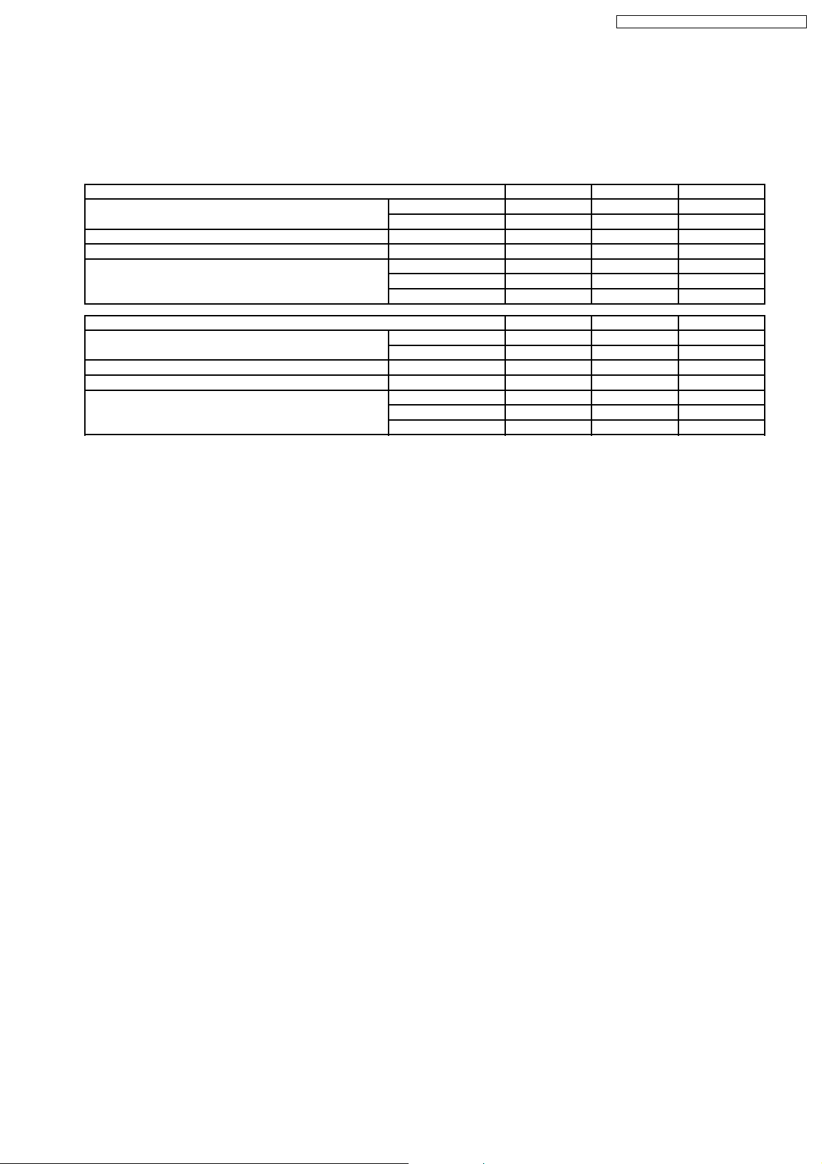
Comparison chart
File Type 1GB
2
Approx. Number of JPEG Photos3(1,600 x 1,200) Standard 2325 1209 600
Fine 1162 604 300
Approx. Time of MPEG4 Video (Using the D-snap SV-AV50) 384 Kbps, 12 fps 370 min. 180 min. 90 min.
Approx. Time of MPEG2 Video (Using the D-snap SV-AV100) 6 Mbps, 30 fp3 20 min. 10 min. 5 min.
Approx. Time of Recording Capacity for Music
(AAC/MP3/WMA)
4
High Quality (128kbps) 8h. 44 min. 4h. 20 min.
Normal (96kbps) 11h. 38 min. 5h. 46 min.
Long Play (64kbps) 17h. 28 min. 8h. 40 min.
File Type 128MB
1
Approx. Number of JPEG Photos3(1,600 x 1,200) Standard 301 149 72
Fine 150 74 36
Approx. Time of MPEG4 Video (Using the D-snap SV-AV50) 384 Kbps, 12 fps 40 min. 20 min. 10 min.
Approx. Time of MPEG2 Video (Using the D-snap SV-AV100) 6 Mbps, 30 fp3 N/A N/A N/A
Approx. Time of Recording Capacity for Music
(AAC/MP3/WMA)
4
High Quality (128kbps) 2h. 10 min. 1h. 4 min. 31 min.
Normal (96kbps) 2h. 54 min. 1h. 26 min. 42 min.
Long Play (64kbps) 4h. 21 min. 2h. 9 min. 1h. 3 min.
512MB
64MB
1
1
256MB
32MB
1
1
For Notes
1. MB = 1 million bytes. Usable capacity will be less.
2. GB = 1 billion bytes. Usable capacity will be less.
3. For normal shooting of 1,600 x 1,200 /static/Content. These figures vary depending on the subject being photographed and
on the particular model.
4. Approximate recording time in AAC format.
15
Page 16

SA-PM71SDE / SA-PM71SDEB / SA-PM71SDEG
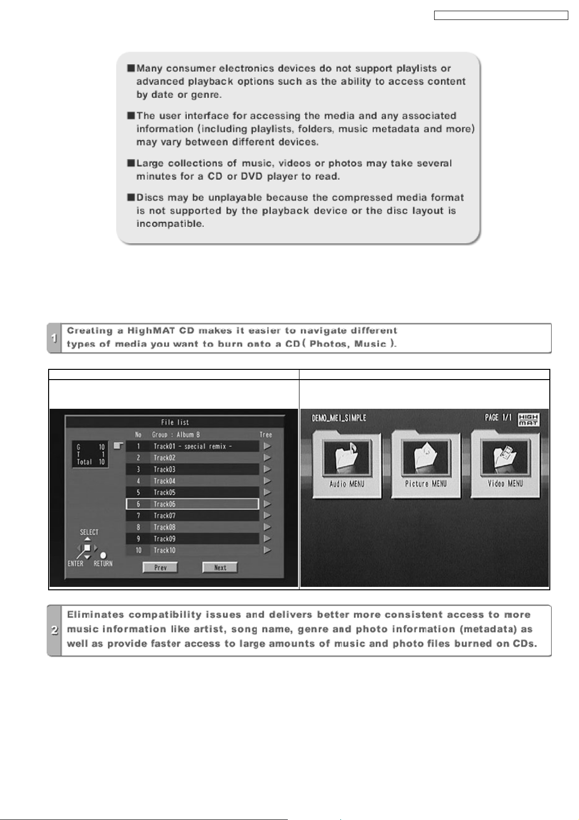
12 About HighMAT
12.1. What’s HighMAT?
Consumers worldwide are using PCs to create their own collections of music, photos and even video by burning them onto CDs.
But how these collections can be experie nced across different devices can be confusing to navigate, time consuming to access for
a DVD player, and be incomplete in terms of music information available to the customer.
HighMAT offers a solution to this growing consumer problem. HighMAT dramatically improves the digital media experience on
consumer electronic devices by delivering a simple, standardized approach that allows consumers who have created personal
collections of digital music, photography and video on their PC to:
· Create a HighMAT CD or DVD which can be easily played back on consum er electronics devices such as CD and DVD players,
and car stereos.
· Move digital media files (using recordable media such as CD-R and CD-RW) between the PC and various playback devices
such as CD and DVD players.
A new standard for creating personal media on consumer electronic devices, HighMAT enable easier and more seamless
interoperability between Windows PCs and devices designed for your living room, or the car.
12.2. Why take advantage of HighMAT?
A Problem Defined:Today, when consum ers create their own digital audio, video or photo collections on CD-R or other physical
formats, there are numerous, inconsistent ways that devices read the data. For the consumer, the playback experience can be
confusing:
16
Page 17
SA-PM71SDE / SA-PM71SDEB / SA-PM71SDEG
A Solution Created: HighMAT delivers a better digital media access experience by creating a standard approach for PCs to
structure digital media on various physical formats and for playba ck devices to read the data.
12.3. Benefits of HighMAT?
Conventional HighMAT
Even though DVD player is CD-R/RW compatible, the inconsistent ways
that various DVD players can read the music or photos files often leads
to a confusing and inconsistant playback experince.
HighMAT compatible products play content back with consistent
interface. This includes products which are JPEG compatible products
without HighMAT support.
17
Page 18
SA-PM71SDE / SA-PM71SDEB / SA-PM71SDEG
18
Page 19
SA-PM71SDE / SA-PM71SDEB / SA-PM71SDEG
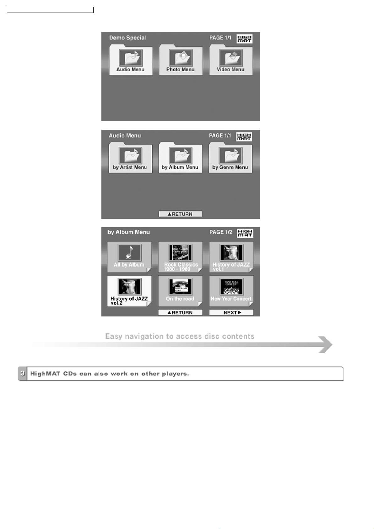
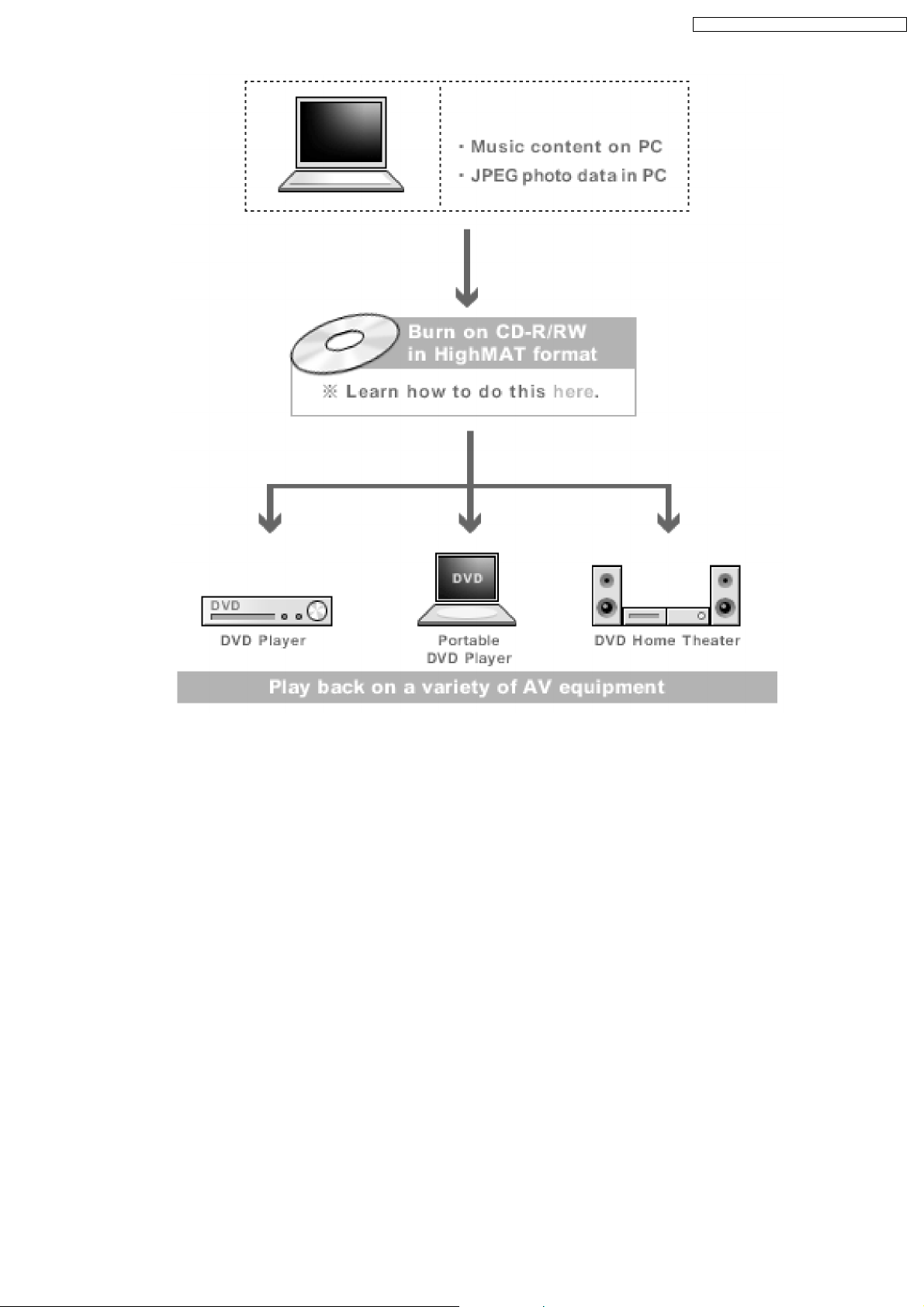
HighMAT is now available for CD Burning and in Leading DVD PlayersHighMAT is a new technology that is now available in leading
software and consumer electronic devices to dramatically improve the digital media experience when you create homemade
CDsHighMAT delivers a simple, standardized way for PC software and consum er electronics devices to talk to each other and work
better together.
When you create your homemade CDs with software that supports HighMAT CD burning, and then play them back on a DVD
player that supports HighMAT, you get better, easier navigation. You get folders you can access with a single click of your DVD
player´s remote control. You can view important information about your music like full song names, artist titles, album names and
genre. And you can get faster startup on your home entertainment device.
To enjoy the benefits of HighMAT, all you need is software that supports HighMAT for CD burning of music or photos, as well as
a home entertainment device like a DVD player that supports HighMAT for playback. Always look for the HighMAT logo on your
software or home entertainment device to ensure it supports the HighMAT experience.
19
Page 20

SA-PM71SDE / SA-PM71SDEB / SA-PM71SDEG
13 Assembling and Disassembling
“ATTENTION SERVICER”
Some chassis components may be have sharp edges. Be careful when disassembling and servicing.
1. This section describes procedures for checking the operation of the major printed circuit boards and replacing the main
components.
2. For reassembly after operation checks or replacement, reverse the respective procedures.
Special reassembly procedures are described only when required.
3. Select items from the following index when checks or replacement are required.
· Disassembly of Side Panel L & R
· Disassembly of Top Cabinet
· Disassembly of Deck Mechanism P.C.B. and Tape Eject P.C.B.
· Disassembly of Front Panel
· Disassembly of SD Module P.C.B.
· Disassembly of Panel P.C.B.
· Disassembly of Rear Cabinet
· Disassembly of Main P.C.B.
· Disassembly of Transformer P.C.B.
· Disassembly of Tuner Pack
· Disassembly of Power P.C.B.
· Disassembly of CR16 Mechanism
Warning:
This product uses a laser diode. Refer to “Precaution of Laser Diode”.
ACHTUNG:
Die Lasereinheit nicht zerlegen.
Die Lasereinheit darf nur gegen eine vom Hertsteller spezifizierte Einheit ausgetauscht werden.
13.1. Disassembly flow chart
The following chart is the procedure for disassembling the casing and inside parts for internal inspection when carrying out the
servicing.
To assemble the unit, reverse the steps shown in the chart below.
20
Page 21
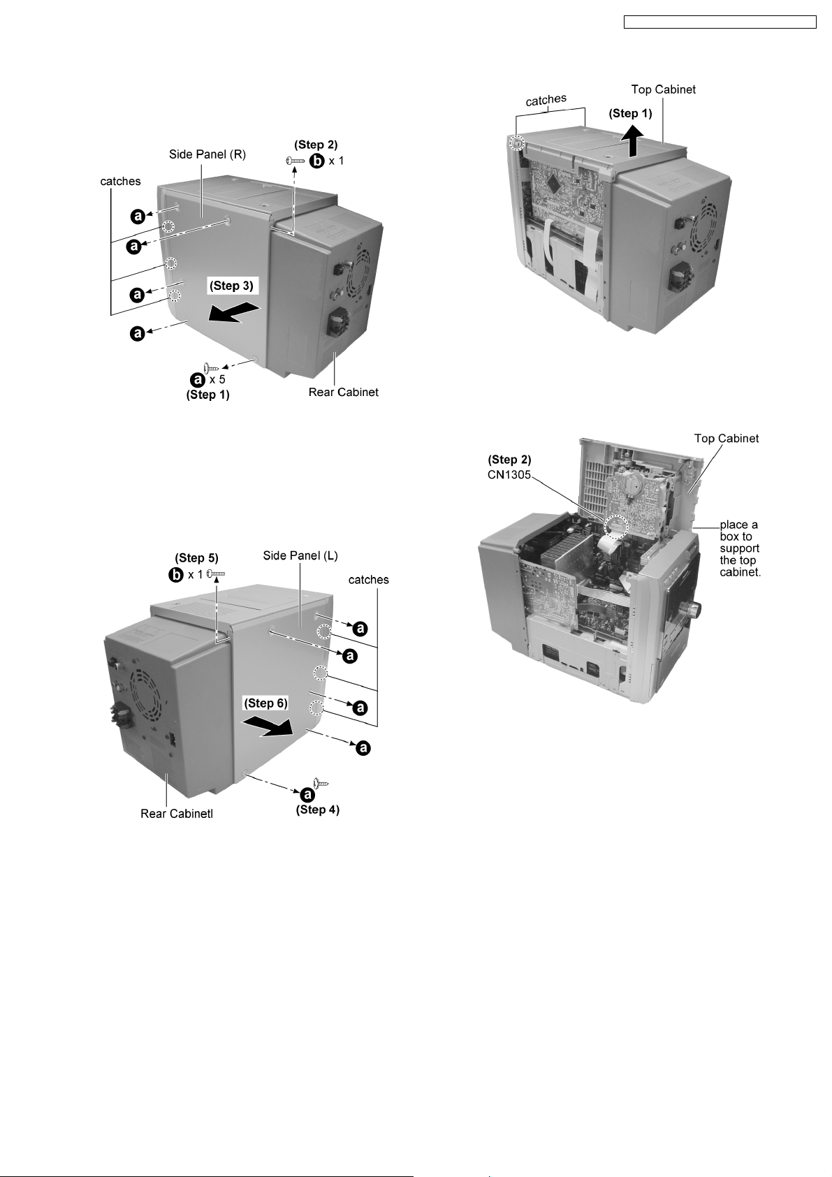
13.2. Disassembly of Side Panel L &
R
SA-PM71SDE / SA-PM71SDEB / SA-PM71SDEG
Step 1 : Lift up the top cabinet as arrow shown (Be careful of
the catches).
Step 1 : Remove 5 screws from the side panel (R).
Step 2 : Remove 1 screws from the corner of the side panel
(R).
Step 3 : Remove the side panel as arrow shown (Be careful of
the catches).
Step 4 : Remove 5 screws from the side panel (L).
Step 5 : Remove 1 screws from the corner of the side panel (L).
Step 6 : Remove the side panel as arrow shown (Be careful of
the catches).
Step 2 : Place the top cabinet as shown and detach the
connector CN1305.
13.4. Disassembly of Deck
Mechanism P.C.B. and Tape
Eject P.C.B.
· Follow the (Step 1) - (Step 6) of item 13.2.
· Follow the (Step 1) - (Step 2) of item 13.3.
13.3. Disassembly of Top Cabinet
· Follow the (Step 1) - (Step 6) of item 13.2.
21
Page 22
SA-PM71SDE / SA-PM71SDEB / SA-PM71SDEG
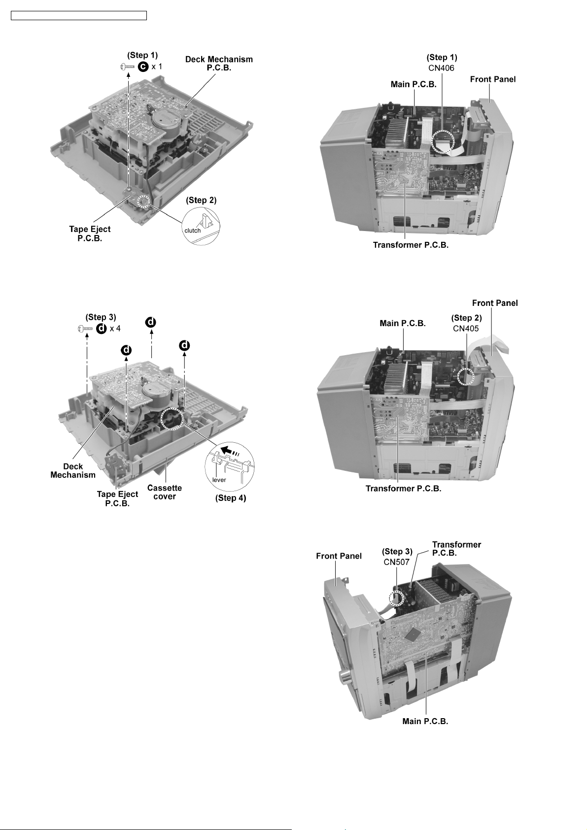
Step 1 : Remove 1 screw.
Step 2 : Release the clutch and remove the Tape Eject P.C.B..
Step 3 : Remove 4 screws.
Step 4 : Push the lever as arrow shown to remove the Deck
Mechanism.
Step 1 : Detach the connector CN406.
Step 2 : Detach the connector CN405.
13.5. Disassembly of Front Panel
· Follow the (Step 1) - (Step 6) of item 13.2.
· Follow the (Step 1) - (Step 2) of item 13.3.
Step 2 : Detach the connector CN507.
22
Page 23

SA-PM71SDE / SA-PM71SDEB / SA-PM71SDEG
Step 2 : Remove shield plate. (Be careful of the catches)
Step 4 : Release 2 catches.
Step 5 : Release the catch at the bottom cabinet and remove
the front panel as arrow shown.
13.6. Disassembly of SD Module
P.C.B.
· Follow the (Step 1) - (Step 6) of item 13.2.
· Follow the (Step 1) - (Step 2) of item 13.3.
· Follow the (Step 1) - (Step 5) of item 13.5.
Step 3 : Unsolder 4 point to remove SD Module P.C.B..
13.7. Disassembly of Panel P.C.B.
· Follow the (Step 1) - (Step 6) of item 13.2.
· Follow the (Step 1) - (Step 2) of item 13.3.
· Follow the (Step 1) - (Step 5) of item 13.5.
· Follow the (Step 1) of item 13.6.
Step 1 : Remove 2 screws to remove the SD Module P.C.B.
with shield plate as arrow shown.
23
Page 24
SA-PM71SDE / SA-PM71SDEB / SA-PM71SDEG
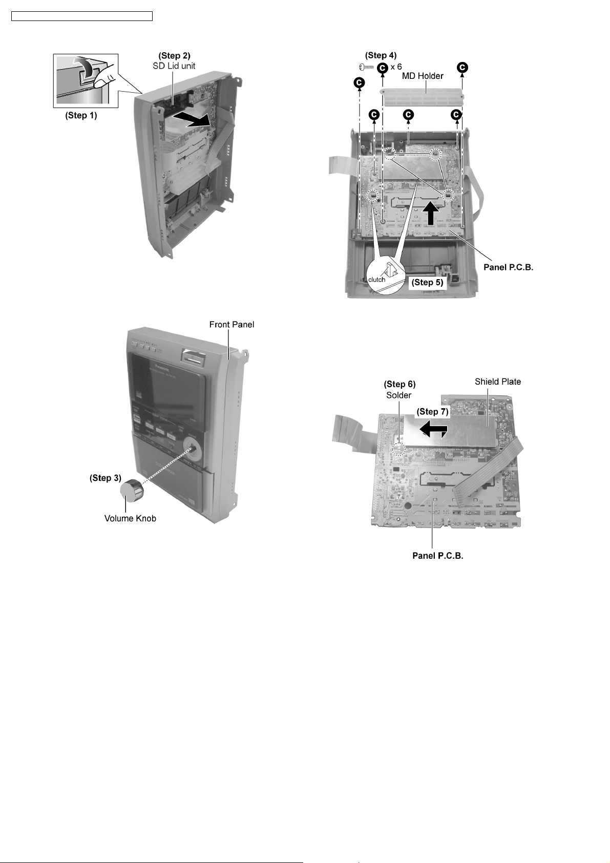
Step 1 : Flip open the SD cover as arrow shown.
Step 2 : Remove the SD Lid unit as arrow shown.
Step 3 : Remove the volume knob.
Step 4 : Remove 6 screws and MD Holder.
Step 5 : Release 4 clutches and remove the Panel P.C.B. as
arrow shown.
Step 6 : Unsolder the shield plate.
Step 7 : Remove the shield plate as arrow shown.
13.8. Disassembly of Rear Cabinet
· Follow the (Step 1) - (Step 6) of item 13.2.
· Follow the (Step 1) - (Step 2) of item 13.3.
24
Page 25
SA-PM71SDE / SA-PM71SDEB / SA-PM71SDEG
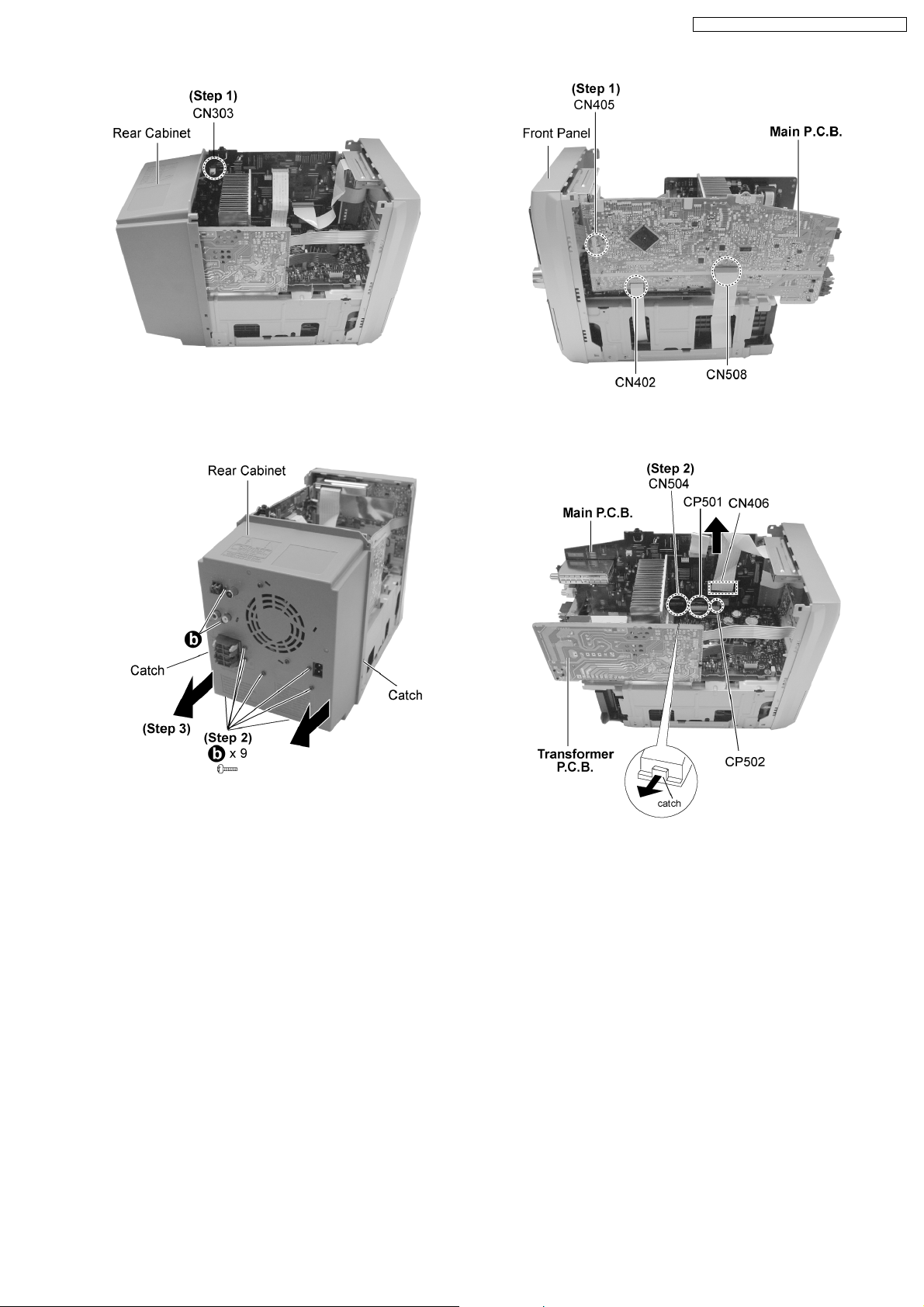
Step 1 : Detach the connector CN303.
Step 2 : Remove 9 screws altogether.
Step 3 : Remove the rear cabinet as arrows shown (Be careful
of the catches).
13.9. Disassembly of Main P.C.B.
· Follow the (Step 1) - (Step 6) of item 13.2.
· Follow the (Step 1) - (Step 2) of item 13.3.
· Follow the (Step 1) - (Step 3) of item 13.8.
Step 1 : Detach the connector CN405 , CN402 and CN508.
Step 2 : Detach the connectors CN406.
Step 3 : Releas e the catch as arrow shown and detach the
connector CN504, CP501 and CP502 and pull out the Main
P.C.B. as arrow shown.
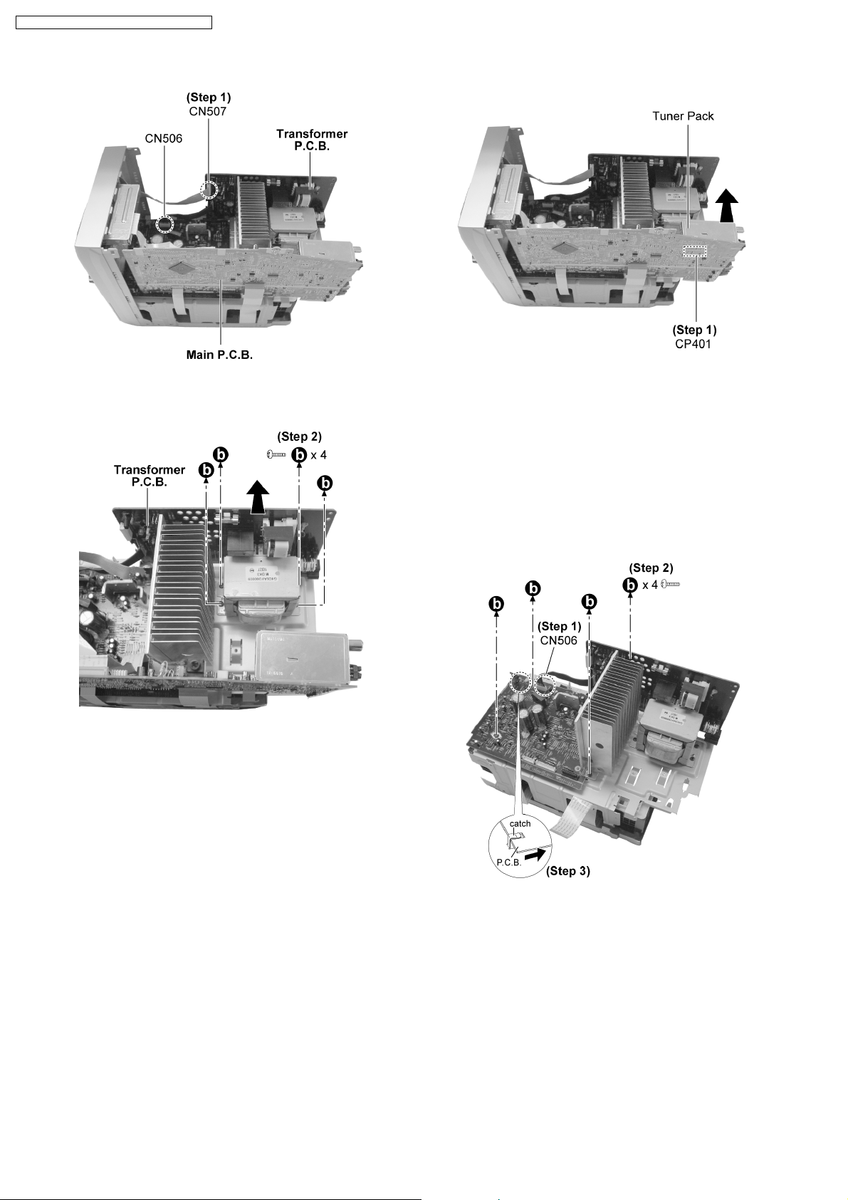
13.10. Disassembly of Transformer
P.C.B.
· Follow the (Step 1) - (Step 6) of item 13.2.
· Follow the (Step 1) - (Step 2) of item 13.3.
· Follow the (Step 1) - (Step 3) of item 13.8.
25
Page 26
SA-PM71SDE / SA-PM71SDEB / SA-PM71SDEG
Step 1 : Detach the connectors CN506 and CN507.
Step 2 : Remove 4 screws and pull out the Transformer P.C.B.
as arrow shown.
13.11. Disassembly of Tuner Pack
Step 1 : Detach the connector CP401 and remove the tuner
pack as arrow shown.
13.12. Disassembly of Power P.C.B.
· Follow the (Step 1) - (Step 6) of item 13.2.
· Follow the (Step 1) - (Step 2) of item 13.3.
· Follow the (Step 1) - (Step 5) of item 13.5.
· Follow the (Step 1) - (Step 3) of item 13.8.
· Follow the (Step 1) - (Step 3) of item 13.9.
· Follow the (Step 1) - (Step 6) of item 13.2.
· Follow the (Step 1) - (Step 2) of item 13.3.
· Follow the (Step 1) - (Step 3) of item 13.8.
Step 1 : Detach the connector CN506.
Step 2 : Remove 4 screws.
Step 3 : Remove the Power P.C.B. (Be careful of the catch)
13.13. Disassembly of CR16
Mechanism
· Follow the (Step 1) - (Step 6) of item 13.2.
· Follow the (Step 1) - (Step 2) of item 13.3.
· Follow the (Step 1) - (Step 5) of item 13.5.
26
Page 27
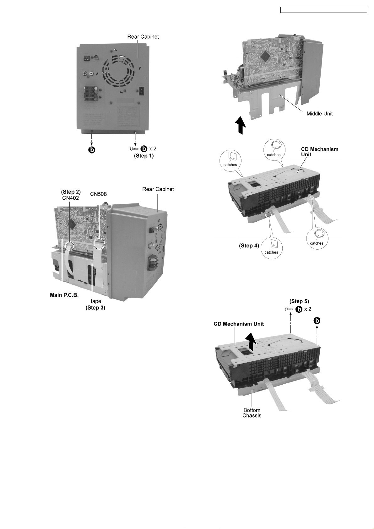
Step 1 : Remove 2 screws.
SA-PM71SDE / SA-PM71SDEB / SA-PM71SDEG
Step 2 : Detach the connectors CN402 and CN508.
Step 3 : Remove the tape which used to secure the FFC
connectors.
Step 4 : Release the catches and remove the middle unit as
arrow shown.
Step 5 : Remove 2 screws and remove the CD Mechanism Unit
from the bottom chassis as arrow shown.
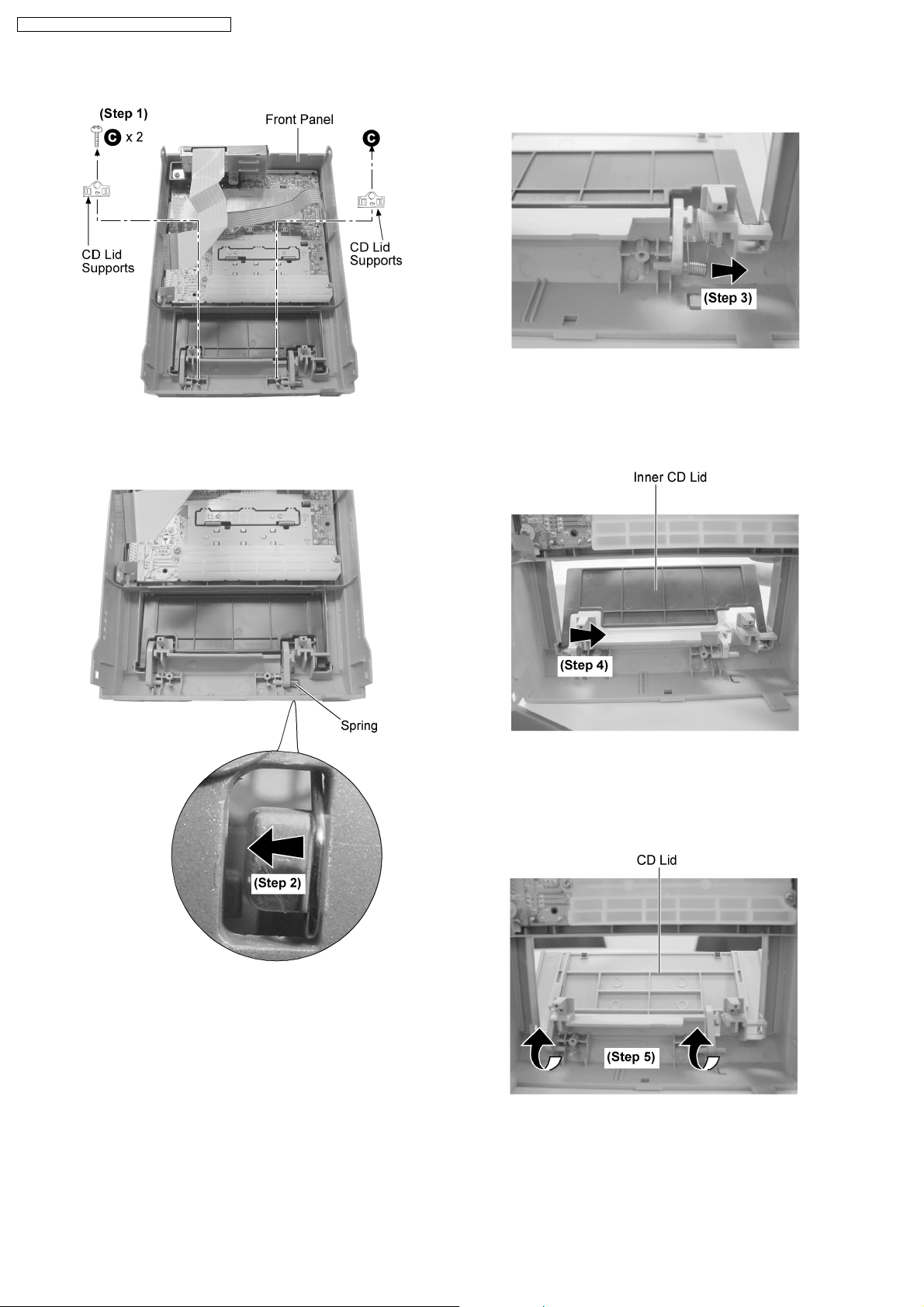
13.14. Replacement of CD Lid and
Inner CD Lid
· Follow the (Step 1) - (Step 6) of item 13.2.
· Follow the (Step 1) - (Step 2) of item 13.3.
27
Page 28
SA-PM71SDE / SA-PM71SDEB / SA-PM71SDEG
· Follow the (Step 1) - (Step 5) of item 13.5.
Step 1 : Remove 2 screws 2 CD Lid supports.
Step 3 : Remove the spring as arrow shown.
Step 2 : Release the spring hook as arrow shown.
Step 4 : Remove the Inner CD Lid as arrow shown.
Step 5 : Remove the CD lid as arrow shown.
28
Page 29
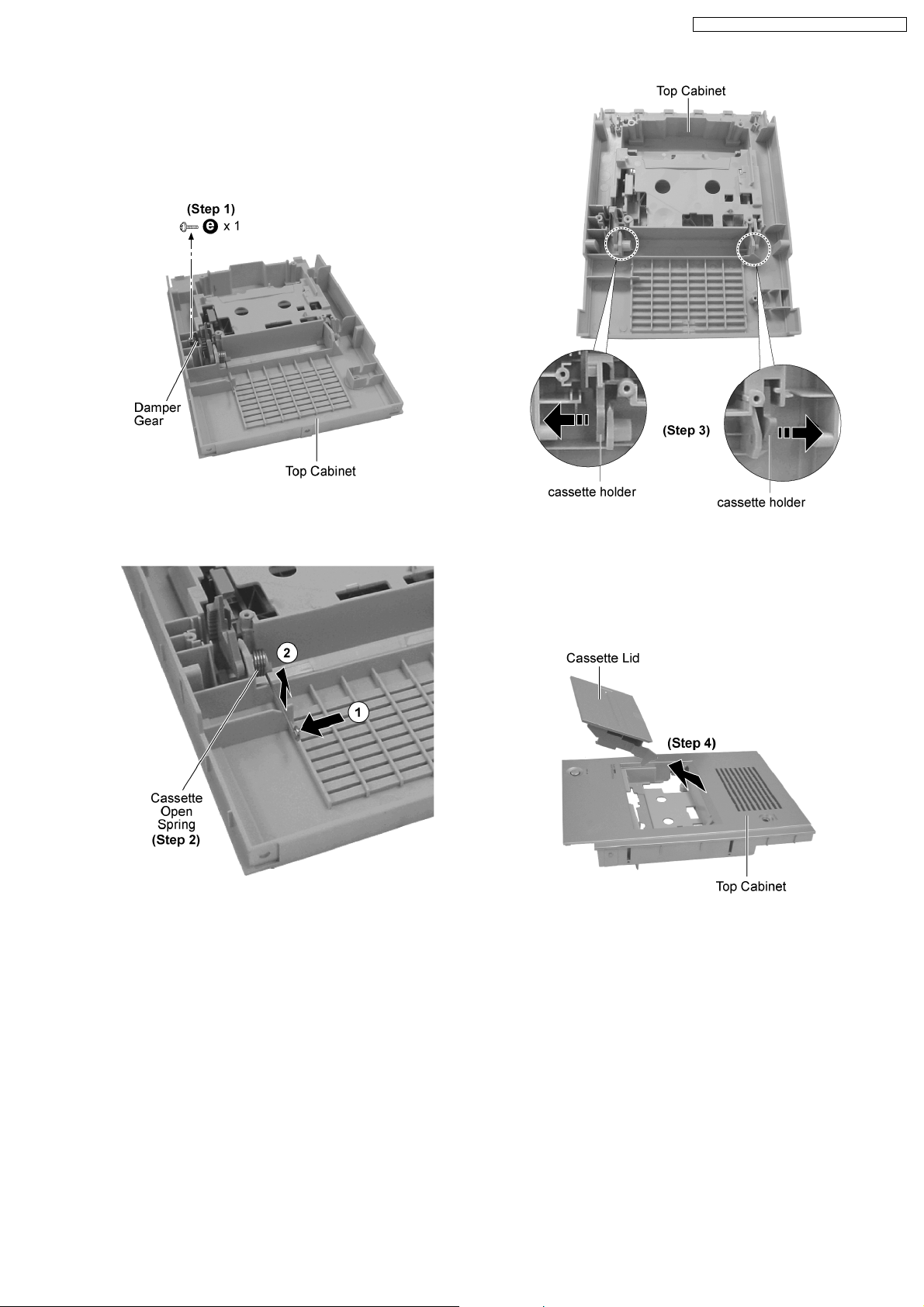
13.15. Replacement of Cassette Lid
· Follow the (Step 1) - (Step 6) of item 13.2.
· Follow the (Step 1) - (Step 2) of item 13.3.
· Follow the (Step 1) - (Step 4) of item 13.4.
SA-PM71SDE / SA-PM71SDEB / SA-PM71SDEG
Step 1 : Remove 1 screw and the damper gear.
Step 2 : Remove the cassette open spring as arrows shown in
order.
Step 3 : Pull both sides cassette holders to the direction of the
arrows shown.
Step 4 : Remove the cassette lid as arrow shown.
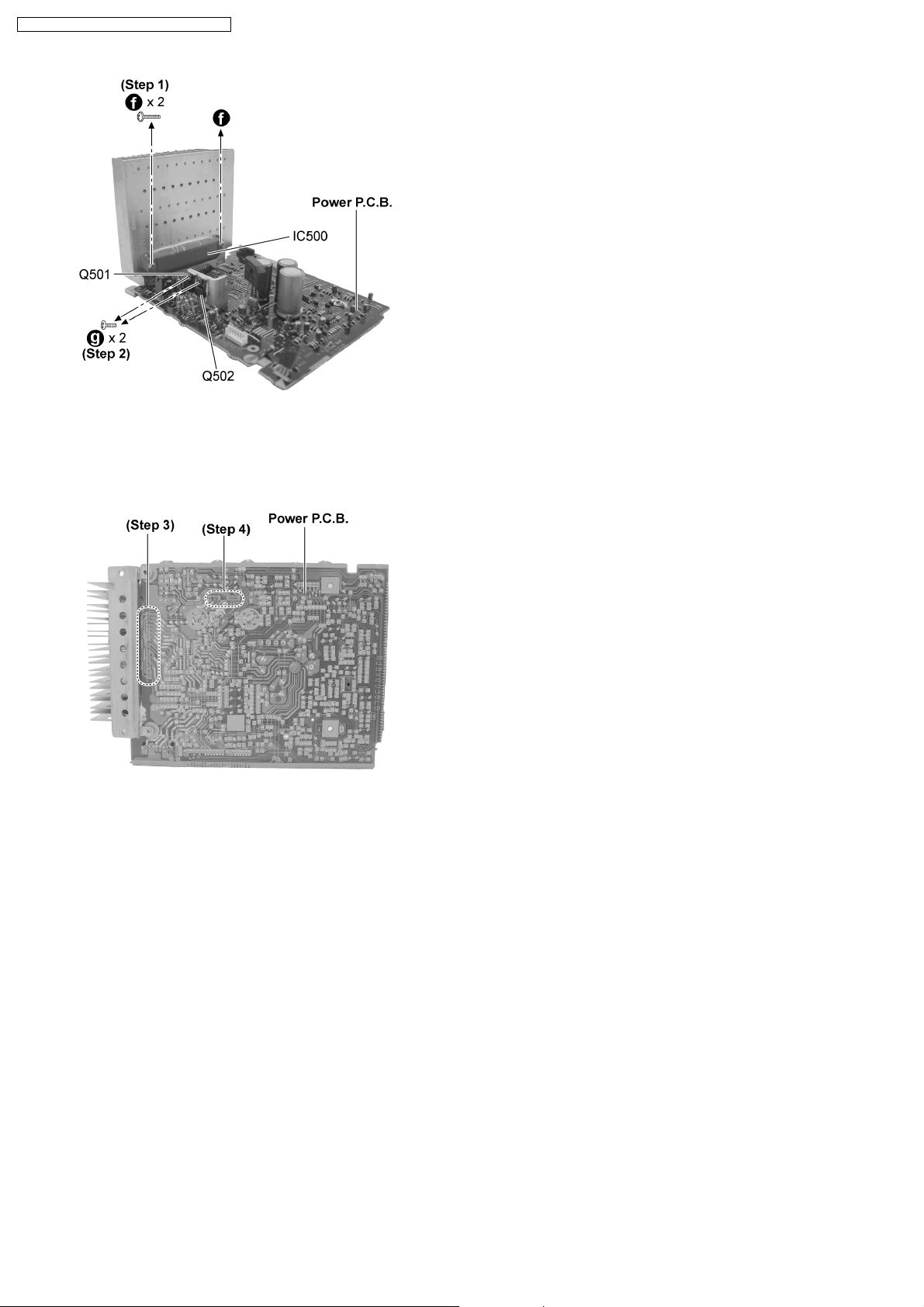
13.16. Replacement of the Power IC
and Transistors
· Follow the (Step 1) - (Step 6) of item 13.2.
· Follow the (Step 1) - (Step 2) of item 13.3.
· Follow the (Step 1) - (Step 5) of item 13.5.
· Follow the (Step 1) - (Step 3) of item 13.8.
· Follow the (Step 1) - (Step 3) of item 13.9.
· Follow the (Step 1) - (Step 3) of item 13.12.
29
Page 30
SA-PM71SDE / SA-PM71SDEB / SA-PM71SDEG
Step 1 : Remove 2 screws.
Step 2 : Remove 2 screws.
Step 3 : Unsolder the Power IC500.
Step 4 : Unsolder the Transistor Q501 and Q502.
30
Page 31

SA-PM71SDE / SA-PM71SDEB / SA-PM71SDEG
13.17. Procedure for Replacing Pinch Roller and Head Block (Deck
Mechanism Unit)
· Follow the (Step 1) - (Step 6) of Item 13.2.
· Follow the (Step 1) - (Step 2) of Item 13.3.
· Follow the (Step 1) - (Step 4) of Item 13.4.
13.18. Procedure for Replacing Motor, Capstan Belt A, Capstan Belt B, and
Winding Belt (Deck Mechanism Unit)
· Follow the (Step 1) - (Step 6) of Item 13.2.
· Follow the (Step 1) - (Step 2) of Item 13.3.
· Follow the (Step 1) - (Step 4) of Item 13.4.
· Follow the (Step 1) - (Step 4) of Item 13.17.
31
Page 32

SA-PM71SDE / SA-PM71SDEB / SA-PM71SDEG
32
Page 33

SA-PM71SDE / SA-PM71SDEB / SA-PM71SDEG
13.19. Procedure for Replacing Parts on Deck Mechanism PCB
· Follow the (Step 1) - (Step 6) of Item 13.2.
· Follow the (Step 1) - (Step 2) of Item 13.3.
· Follow the (Step 1) - (Step 4) of Item 13.4.
13.20. Disassembly of CR16 Mechanism
· Follow the (Step 1) - (Step 6) of Item 13.2.
· Follow the (Step 1) - (Step 2) of Item 13.3.
· Follow the (Step 1) - (Step 5) of Item 13.5.
· Follow the (Step 1) - (Step 5) of Item 13.13.
33
Page 34

SA-PM71SDE / SA-PM71SDEB / SA-PM71SDEG
13.21. Replacement of optical pickup unit (CD mechanism)
· Follow the (Step 1) - (Step 6) of Item 13.2.
· Follow the (Step 1) - (Step 2) of Item 13.3.
· Follow the (Step 1) - (Step 5) of Item 13.5.
· Follow the (Step 1) - (Step 5) of Item 13.13.
· Follow the (Step 1) - (Step 2) of Item 13.20.
34
Page 35

SA-PM71SDE / SA-PM71SDEB / SA-PM71SDEG
35
Page 36

SA-PM71SDE / SA-PM71SDEB / SA-PM71SDEG
13.22. Replacement of a traverse gear A and a traverse gear B
· Follow the (Step 1) - (Step 6) of Item 13.2.
· Follow the (Step 1) - (Step 2) of Item 13.3.
· Follow the (Step 1) - (Step 5) of Item 13.5.
· Follow the (Step 1) - (Step 5) of Item 13.13.
· Follow the (Step 1) - (Step 2) of Item 13.20.
· Follow the (Step 1) - (Step 4) of Item 13.21.
36
Page 37

SA-PM71SDE / SA-PM71SDEB / SA-PM71SDEG
13.23. Procedure for removing CD loading mechanism
1. Turn off by pressing power SW in the body.
2. Unplug AC power cord after the indication of [GOOD-BYE],
then disassemble the body.
3. Disassemble the body, and take out CD loading
mechanism.
4. Perform disassembly according to the following procedure
for disassembly.
13.24. CR16 mechanism disassembly procedure
13.24.1. Gear for servicing information
· This unit has a gear which used for checking items
(open/close of disc tray, up/down operation of traverse unit
by manually) when servicing. (For gear information, that is
described on the items for disassembly procedures.)
· For preparation of gear (for servicing), perform the
procedures as follows.
· In case of re-servicing the same set, the “ gear for servicing”
may be took off becaus e it had been used. So, the “gear for
servicing” must be stored.
1. Remove the gear attached to top cover of CD loading
mechanism.
2. Insert the hexagonal wrench (2.5mm) into the gear.
37
Page 38

SA-PM71SDE / SA-PM71SDEB / SA-PM71SDEG
13.24.2. Replacement for the disc tray
· Follow the (Step 1) - (Step 6) of Item 13.2.
· Follow the (Step 1) - (Step 2) of Item 13.3.
· Follow the (Step 1) - (Step 5) of Item 13.5.
· Follow the (Step 1) - (Step 5) of Item 13.13.
38
Page 39

SA-PM71SDE / SA-PM71SDEB / SA-PM71SDEG
39
Page 40

SA-PM71SDE / SA-PM71SDEB / SA-PM71SDEG
13.24.3. Replacement for the traverse deck
· Follow the (Step 1) - (Step 6) of Item 13.2.
· Follow the (Step 1) - (Step 2) of Item 13.3.
· Follow the (Step 1) - (Step 5) of Item 13.5.
· Follow the (Step 1) - (Step 5) of Item 13.13.
· Follow the (Step 1) - (Step 10) of Item 13.24.2
13.24.4. Disassembly for CD loading unit
· Follow the (Step 1) - (Step 6) of Item 13.2.
· Follow the (Step 1) - (Step 2) of Item 13.3.
· Follow the (Step 1) - (Step 5) of Item 13.5.
· Follow the (Step 1) - (Step 5) of Item 13.13.
· Follow the (Step 1) - (Step 10) of Item 13.24.2
· Follow the (Step 1) - (Step 4) of Item 13.24.3
40
Page 41

SA-PM71SDE / SA-PM71SDEB / SA-PM71SDEG
41
Page 42

SA-PM71SDE / SA-PM71SDEB / SA-PM71SDEG
42
Page 43

SA-PM71SDE / SA-PM71SDEB / SA-PM71SDEG
13.25. CR16 MECHANISM ASSEMBLY
PROCEDURE
The following specified greases and/or oil must be applied
when some specific parts are changed.
1. Floil grease (VFK1298) : The floil grease must be
applied to tray, tray (L) and tray (R).
2. Hanarl oil (VFK1700) : The hanarl oil must be applied to
any parts with grease other than the said parts.
· Follow the (Step 1) - (Step 6) of Item 13.2.
· Follow the (Step 1) - (Step 2) of Item 13.3.
· Follow the (Step 1) - (Step 5) of Item 13.5.
· Follow the (Step 1) - (Step 2) of Item 13.10.
· Follow the (Step 1) - (Step 5) of Item 13.13.
· Follow the (Step 1) - (Step 10) of Item 13.24.2
· Follow the (Step 1) - (Step 4) of Item 13.24.3
· Follow the (Step 1) - (Step 22) of Item 13.24.4
43
Page 44

SA-PM71SDE / SA-PM71SDEB / SA-PM71SDEG
44
Page 45

SA-PM71SDE / SA-PM71SDEB / SA-PM71SDEG
45
Page 46

SA-PM71SDE / SA-PM71SDEB / SA-PM71SDEG
46
Page 47

SA-PM71SDE / SA-PM71SDEB / SA-PM71SDEG
47
Page 48

SA-PM71SDE / SA-PM71SDEB / SA-PM71SDEG
48
Page 49

SA-PM71SDE / SA-PM71SDEB / SA-PM71SDEG
49
Page 50

SA-PM71SDE / SA-PM71SDEB / SA-PM71SDEG
50
Page 51

SA-PM71SDE / SA-PM71SDEB / SA-PM71SDEG
51
Page 52

SA-PM71SDE / SA-PM71SDEB / SA-PM71SDEG
52
Page 53

SA-PM71SDE / SA-PM71SDEB / SA-PM71SDEG
53
Page 54

SA-PM71SDE / SA-PM71SDEB / SA-PM71SDEG
54
Page 55

SA-PM71SDE / SA-PM71SDEB / SA-PM71SDEG
55
Page 56

SA-PM71SDE / SA-PM71SDEB / SA-PM71SDEG
13.26. Disassembly of traverse mechanism
· Follow the (Step 1) - (Step 6) of Item 13.2.
· Follow the (Step 1) - (Step 2) of Item 13.3.
· Follow the (Step 1) - (Step 5) of Item 13.5.
· Follow the (Step 1) - (Step 5) of Item 13.13.
· Follow the (Step 1) - (Step 2) of Item 13.20.
56
Page 57

SA-PM71SDE / SA-PM71SDEB / SA-PM71SDEG
13.27. Handling of cassette tape jam
· Follow the (Step 1) - (Step 6) of Item 13.2.
Step 1 : If the cassette tape cannot eject due to twinning
around capstan or pinch roller during play or record, rotate the
flywheel F as arrow shown to remove twined tape.
Step 2 : Push the lever as arrow shown to open the cassette lid
and remove the cassette tape.
57
Page 58

SA-PM71SDE / SA-PM71SDEB / SA-PM71SDEG
14 Service Positions
14.1. Checking procedure
Note : For the disassembling procedure, see the section 13.
14.2. Checking the major P.C.B
1. Disassembly of Side Panel L & R
2. Disassembly of Top Cabinet
3. Disassembly of Deck Mechanism P.C.B and Tape Eject P.C.B
4. Disassembly of Front Panel
5. Disassembly of SD Module P.C.B
6. Disassembly Panel P.C.B
7. Disassembly of Rear Cabinet
8. Disassembly of Main P.C.B
9. Disassembly of Transformer P.C.B
10. Disassembly of Power P.C.B
11. Disassembly of CR16 mechanism
58
Page 59

SA-PM71SDE / SA-PM71SDEB / SA-PM71SDEG
15 Self-Diagnostic Display Function
This unit is equipped with a self-diagnostic display function, which will be useful during servicing and maintenance.
· Refer to the next page for display symbols, symptoms, etc.
15.1. Entering into Self-Diagnostic Mode
15.1.1. Setting of Self-Diagnostic (Doctor Mode)
a) Turn on power for unit.
b) Select SD Stop Mode.
c) Press and hold [STOP n/-DEMO] button for at least 2 seconds, follow by [4] and [7] on remote control. In the case where there
is EEPRO M, then, the display should be as below:
15.1.2. Rom Correction Checksum and Micro-p version
a) Turn on power for unit.
b) Select CD Mode.
c) Press and hold [STOP n/-DEMO] button for at least 2 seconds, follow by [4] and [7] on remote control. In the case where there
is EEPRO M, then, the display should be as below:
59
Page 60

SA-PM71SDE / SA-PM71SDEB / SA-PM71SDEG
15.2. Error Code Table
15.2.1. Error codes for CR 16
Mode Present After modify Description
Initialize F17 F17
F17P Play
F22 F22
F22L Load
F22T Trouble
F22U Unload
F27 F27
F27T Trouble
F27P Play
F28 F22
F28P Play
Load/Unload F28 LOAD Load
F29 UNLOAD Unload
Disc Change F27 DCHU Disc change up
DCHD Disc change down
Single open / close F28 NSCL Normal single close
F29 NSOP Normal single open
Single open / close during play F27 PSOU Play single open up
PSOD Play single open down
PSCU Play single close up
PSCD Play single close down
F28 PSCL Play single close
F29 PSOP Play single open
All open / close H16 H16
F27 NAOU Normal all open up
NACD Normal all close down
F28 NACL Normal all close
F29 NAOP Normal all open
All open / close during play F27 PAOU Play all open up
PACD Play all close down
F28 PACL Play all close
F29 PAOP Play all open
Lock for shipment F27 LOCK Lock
Total of kind 5 33
Display of error code
1. Upon occurrence of error, a maximum of 5 will be displayed.
2. Upon occurrence of error, indication will be from number 1.
3. Upon occurrence of the same error time, the error will be displayed twice.
Example:
60
Page 61

SA-PM71SDE / SA-PM71SDEB / SA-PM71SDEG
1st occurrence ......... ERROR 1 DCHU
2nd occurrence ......... ERROR 2 NSOP
3rd occurrence ......... ERROR 3 PAOP
4th occurrence ......... ERROR 4 PAOP
5th occurrence ......... ERROR 5 NSOP
15.2.2. Error codes for Deck Mechanism
Error Code Abnormal Items Possible Cause
H01 MODE SW abnormal Normal operation during mecha transition, MODE SW abnormal is memorised. The content
H02 REC INH SW abnormal
H03 HALF SW abnormal
H06 Cr02 SW abnormal
F01 Reel pulse abnormal
F02 TPS abnormal
of abnormality can be confirmed in the abnormal detection mode explained in the later
section.
The content of abnormality can be confirmed in the abnormal detection mode explained in
the later section.
15.3. Changer Reliability Test Mode
1. After entering the inspection mode, push button [12] on the remote control for reliability testing mode.
2. Follow the flow process below
3. During the aging process, pressing the [PROGRAM] button will stop the process, and return it to NORMAL mode.
4. Enter the service mode.
5. Press,[
· DVD/CD function set to automatic mode.
· Input a Disc into each tray.
6. Set display uses 4-digit for counter display.
· [PLAYCHECK 0000] to max [PLAYCHECK 9999].
7. After 1 cycle process is completed, FL counter will display [1] count up from [0000] to max [9999]. From [9999] count up [1] will
display [0000].
8. During mechanism operation in test mode, if time over error occurs with arnormal operations, do not retry but stop the test
instead.
9. To exit from Test mode power off the set.
10. If during test mode, after TOC reading of disc and [NO DISC] [NO PLAY] is indicated, stop the test here. (Keep the counter
displayed in the same state as when it was stopped.) Do not reopen the reliability test mode after it stops,
11. Go back to [1] after 1 cycle finishe s.
· After 1 cycle process is completed, FL counter will display [1] count up from [0000] to max [9999]. From [9999] count up [1]
10], [2] with the settings below.
will display [0000] .
61
Page 62

SA-PM71SDE / SA-PM71SDEB / SA-PM71SDEG
16 Procedure for Checking Operation of Individual Parts of
Deck Mechanism Unit
16.1. Operation Check with Cassette Tape
1. Pull up the EJECT lever using a rubber band. (Fig. 6)
2. Supply DC5V to MOTOR. (→ MOTOR rotates.) (Fig. 5)
3. Insert a cassette tape to the unit.
4. Supply DC9V to the plunger, and turn the power ON and OFF. (→ Power +PL, -PL) (Fig. 5)
a. FWD PLAY: Supply the plunger power in a flash. (ON: approx. 5msec)
b. FWD FF: Supply the plunger power in a flash at PLAY mode. (ON: approx. 5msec)
c. STOP: Supply the plunger power in a flash at FWD FF mode. (ON: approx. 5msec)
d. REV PLAY: Supply the plunger power in a normal timing at STOP mode. (ON: approx. 200msec)
e. REV REW: Supply the plunger power in a flash at REV PLAY mode. (ON: approx. 50msec)
f. STOP: Supply the plunger power in a flash at FF mode. (ON: approx. 50msec)
Repeat the operation (→ FWD PLAY)
(Note) Other operation may start if a timing of supplying the plunger power is missed.
16.1.1. Connection Status between Mechanism and Power Supply (Motor, Plunger)
16.1.2. Operative Parts of Mechanism Unit (EJECT lever fitted with rubber band,
Plunger/Rib operation)
Fig. 6
16.2. Operation Check without Cassette Tape
1. Pull up the EJECT lever using a rubber band. (Fig. 6)
2. Supply DC5V to MOTOR. (→ MOTOR rotates.)
3. Lift up the mechanism unit’s plunger/rib with the tip of a negative screwdriver, and operate the unit in the same timing as
supplying the power. (Fig. 7)
62
Page 63

Fig. 7
SA-PM71SDE / SA-PM71SDEB / SA-PM71SDEG
63
Page 64

SA-PM71SDE / SA-PM71SDEB / SA-PM71SDEG
17 Measurement And Adjustments
17.1. Cassette Deck Section
17.1.1. Requirements
· Test tape (QZZCFM) (QZZCWAT)
· Normal blank cassette tape (QZZCRA)
· Digital frequency counter
· Oscilloscope
· Electrical voltmeter
· Headphone jack output jig (Fig. 8)
17.1.2. Setting of Unit
· VOLUME: MAX
17.1.3. Preparations
1. Apply under [13. Assembling and Disassembling].
2. Remove 4 screws from the mechanism unit to disassemble. under [13. Assembling and Disassembling].
3. Connect the headphone jack output jig (Fig. 8) to headphone jack.
Fig. 8
Fig. 9
17.1.4. Tape Speed Adjustment
· Normal speed adjustment (only during forward playback)
(Product reference value: 3,000±90Hz)
1. Connect a frequency indicator. (Fig. 12)
2. Playback the middle portion of the test tape (QZZCWAT).
3. Adjust the motor screw so that the following output level is produced. (Fig. 10)
Adjustment Range: 3,000 ± 90Hz (a constant speed)
64
Page 65

17.1.5. Bias Voltage Check
1. Connect an electrical voltmeter. (Fig. 9) (Fig. 12)
2. Set the function to “TAPE” position.
3. Insert a normal blank cassette tape (QZZCRA).
4. While pressing and holding down [REC (
pressing the buttons till the recording pause mode is activated.)
5. Check that the output level is within the standard range.
Standard Range: 14 ± 4mV
/ )] button, press [TAPE ( )] button to pause the recording mode. (Repeat
SA-PM71SDE / SA-PM71SDEB / SA-PM71SDEG
Fig. 10
Fig. 11
Fig. 12
17.1.6. Bias Frequency Check
1. Connect a digital frequency counter (Fig. 13).
2. Set the function to “TAPE” position.
3. Insert a normal blank cassette tape (QZZCRA) and press “REC” mode on main unit.
4. Check that the output frequency is within the standard range.
Standard Value: 98 ±8 kHz
Fig. 13
65
Page 66

SA-PM71SDE / SA-PM71SDEB / SA-PM71SDEG
18 Voltage Measurement and Waveform Chart
Note:
· Indicated voltage values are the standard values for the unit measured by the DC electronic circuit tester (high-impedance)
with the chassis taken as standard.
Therefore, there may exist some errors in the voltage values, depending on the internal impedance of the DC circuit tester.
· Circuit voltage and waveform described herein shall be regarded as reference information when probing defect point
because it may differ from actual measuring value due to difference of Measuring instrument and its measuring condition
and product itself.
18.1. Voltage Measurement
18.1.1. CD SERVO P.C.B.
CD SERVO P.C.B.
Ref No.
MODE 1234567891011121314151617181920
SD REC 0.2 2.5 3.3 0 2.2 2.1 1.7 1.5 1.6 1.6 2.1 1.2 0 0 0 3.3 0 1.6 1.7 1.6
SD PLAY 0 2.9 3.3 0 0 1.6 1.4 0.4 1.4 1.6 1.5 1.2 0 0.4 3.1 0 0 1.7 1.6 1.6
CD PLAY 0.2 2.5 3.3 0 2.2 2.1 1.7 1.5 1.6 1.6 2.1 1.2 0 0 0 3.3 0 1.6 1.7 1.6
STANDBY 0 -0.2 0.1 00000000000000000
Ref No.
MODE 21 22 23 24 25 26 27 28 29 30 31 32
SD REC 1.7 1.7 1.7 0 1.7 1.7 2.0 2.0 1.8 1.8 1.8 1.8
SD PLAY 1.6 1.6 1.6 1.6 1.6 1.6 1.7 1.7 1.8 1.8 1.8 1.8
CD PLAY 1.7 1.7 1.7 0 1.7 1.7 2.0 2.0 1.8 1.8 1.8 1.8
STANDBY 000000000000
Ref No.
MODE 1234567891011121314151617181920
SD REC 3.3 1.5 1.5 0.3 3.1 1.6 1.5 3.2 1.2 1.2 1.2 1.2 1.2 1.2 1.2 2.4 2.4 1.3 1.3 0
SD PLAY 3.3 0 0 0 3.3 0 0 3.3 3.3 3.3 00003.300000
CD PLAY 3.3 1.5 1.5 0.3 3.1 1.6 1.5 3.2 1.2 1.2 1.2 1.2 1.2 1.2 1.2 2.4 2.4 1.3 1.3 0
STANDBY 0.1 0.1 0.1 0.1 0.1 0.1 0.1 0.1 0.1 0.1 0.1 0.1 0.1 0.1 0.1 0.1 0.1 0.1 0.1 0
Ref No.
MODE 21 22 23 24 25 26 27 28 29 30 31 32 33 34 35 36 37 38 39 40
SD REC 1.5 1.5 1.6 0 1.6 0 1.7 0 3.3 1.7 1.7 1.7 1.7 1.7 0 0 0 3.3 1.6 0.8
SD PLAY 1.5 1.5 1.6 3.3 1.6 0 1.7 0 3.3 1.7 1.7 1.7 1.7 1.7 0.4 3.1 0 0 0.1 0.8
CD PLAY 1.5 1.5 1.6 0 1.6 0 1.7 0 3.3 1.7 1.7 1.7 1.7 1.7 0 0 0 3.3 1.6 0.8
STANDBY 00000000000000000000
Ref No.
MODE 41 42 43 44 45 46 47 48 49 50 51 52 53 54 55 56 57 58 59 60
SD REC 1.6 1.6 1.6 1.6 1.6 3.3 0 1.5 0 1.5 3.0 0 1.5 3.3 3.3 0 0 0 3.3 0
SD PLAY 1.5 0.1 0.3 0 0 3.3 0 1.5 0 1.5 3.0 0 1.5 3.3 00003.30
CD PLAY 1.6 1.6 1.6 1.6 1.6 3.3 0 1.5 0 1.5 3.0 0 1.5 3.3 3.3 0 0 0 3.3 0
STANDBY 00000000000000000000
Ref No.
MODE 61 62 63 64 65 66 67 68 69 70 71 72 73 74 75 76 77 78 79 80
SD REC 3.2 3.2 3.2 0.1 3.3 0.1 0.5 0.1 3.2 0 0.1 0.8 1.6 1.6 3.3 1.6 - 0 1.5 1.0
SD PLAY 00003.30003.203.3001.63.33.33.301.53.3
CD PLAY 3.2 3.2 3.2 0.1 3.3 0 0 0 3.2 0 0 0.8 1.6 1.6 3.3 - 1.6 0 1.5 1.6
STANDBY 00000000000000000000
Ref No.
MODE 1234567891011121314151617181920
SD REC1.601.60000007.74.53.43.63.63.53.73.63.57.70
SD PLAY 1.6 0 1.6 3.3 000007.74.04.03.63.63.63.63.63.67.70
CD PLAY 1.6 0 1.6 0000007.74.53.43.63.63.53.73.63.57.70
STANDBY 0000000000.20.10.10.100.10.10.10.10.20
Ref No.
MODE 21 22 23 24 25 26 27 28
SD REC 7.7 0 0 0 7.7 1.7 1.7 1.7
SD PLAY 7.7 0 0 0 7.7 1.7 1.7 1.7
CD PLAY 7.7 0 0 0 7.7 1.7 1.7 1.7
STANDBY 0.2 0 0 0 0.2 0 0 0
Ref No.
MODE E C B
SD REC 3.2 2.0 2.5
SD PLAY 3.3 0.8 2.9
CD PLAY 3.2 2.0 2.5
STANDBY 0.1 0.1 -0.3
Q701
IC701
IC701
IC702
IC702
IC702
IC702
IC 703
IC 703
66
Page 67

18.1.2. CD LOADING P.C.B
Ref No.
MODE 123456789
SD REC 7.7 0 0 0 7.7 7.7 3.1 0 3.1
SD PLAY 7.7 0 0 0 7.7 7.7 3.1 0 3.1
CD PLAY 7.7 0 0 0 7.7 7.7 3.1 0 3.1
STANDBY 0.1 0.1 0 0.1 0.1 0.1 0 0 0
Ref No.
MODE 123456789
SD REC 7.7 0 0 0 7.7 7.7 3.1 0 3.1
SD PLAY 7.7 0 0 0 7.7 7.7 3.1 0 3.1
CD PLAY 7.7 0 0 0 7.7 7.7 3.1 0 3.1
STANDBY 0.2 0 0 0.1 0.2 0.2 0 0 0
IC 11
CD LOADING P.C.B
IC 21
Ref No.
MODE 1234567891011121314151617181920
CD PLAY 3.8 3.8 3.8 3.8 0 3.8 3.8 3.8 3.8 3.8 3.8 3.8 3.8 3.8 3.8 3.8 3.8 0 0 0
STANDBY -0.1 -0.1 0.4 0.4 0 0.4 0.4 0.4 0.4 0.4 0.4 0.4 0.4 0.4 0.4 0.4 0.4 0 0 0
Ref No.
MODE 21 22 23 24 25 26 27 28 29 30 31 32 33 34 35 36 37 38 39 40
CD PLAY 7.6 0 3.8 3.8 3.8 3.8 3.8 3.8 3.8 3.8 3.8 3.8 3.8 3.8 3.8 3.8 3.8 3.8 3.8 3.8
STANDBY 0.2 0 0.3 0.2 0.2 0.1 0.2 0.2 0.1 0.1 0.2 0.2 0000000.10.1
Ref No.
MODE 12345678
SD REC 0 - - -8.6 0 0 0 8.9
SD PLAY 0 - - -8.6 0 0 0 8.9
CD PLAY 0 - - -8.6 0 0 0 8.9
STANDBY 0 0 0 0.2 0 0 0 0.2
Ref No.
MODE 12345678
SD REC 0 0 0 -8.6 0 - 0 8.9
SD PLAY 0 0 0 -8.6 0 - 0 8.9
CD PLAY 0 0 0 -8.6 0 0 0 8.9
STANDBY 0 0 0 0.2 0 0 0 0.2
Ref No.
MODE 12345678
SD REC 0 0 0 -8.6 - 0 0 8.9
SD PLAY 0 0 0 -8.6 - 0 0 8.9
CD PLAY 0 0 0 -8.6 - 0 0 8.9
STANDBY 0 0 0 0.2 0 0 0 0.2
Ref No.
MODE 12345678
SD REC 3.2 3.2 3.2 3.2 0 3.2 0 0
SD PLAY 3.2 3.2 3.2 3.2 0 3.2 0 0
CD PLAY 3.2 3.2 3.2 3.2 0 3.2 0 0
STANDBY 3.2 3.2 3.2 3.2 0 3.3 0 0
IC205
IC201
IC203
IC201
MAIN P.C.B.
IC206
IC403
18.1.3. MAIN P.C.B.
SA-PM71SDE / SA-PM71SDEB / SA-PM71SDEG
67
Page 68

SA-PM71SDE / SA-PM71SDEB / SA-PM71SDEG
Ref No.
MODE 1234567891011121314151617181920
SD REC 0 3.1 0 3.2 2.7 3.2 2.8 0 3.2 3.2 3.2 3.2 3.2 3.2 0 2.7 3.2 0 3.2 1.8
SD PLAY 0 3.1 0 3.2 2.7 3.2 2.8 0 3.2 3.2 3.2 3.2 3.2 3.2 0 2.7 3.2 0 3.2 1.8
CD PLAY 0 3.1 0 3.2 2.7 3.2 2.8 0 3.2 3.2 3.2 3.2 3.2 3.2 0 2.7 3.2 0 3.2 1.8
STANDBY 0 0 0 3.2 00003.23.23.23.23.23.202.83.200.51.8
Ref No.
MODE 21 22 23 24 25 26 27 28 29 30 31 32 33 34 35 36 37 38 39 40
SD REC3.23.23.23.2- -3.23.23.23.203.200000000
SD PLAY 3.2 3.2 3.2 3.2 - - 3.2 3.2 3.2 3.2 0 3.2 00000000
CD PLAY 3.2 3.2 3.2 3.2 3.2 3.2 3.2 3.2 3.2 3.2 0 3.2 00000000
STANDBY 3.3 3.3 3.3 2.6 00003.33.303.300000000
Ref No.
MODE 41 42 43 44 45 46 47 48 49 50 51 52 53 54 55 56 57 58 59 60
SD REC3.23.23.23.201.201.23.200000003.23.200
SD PLAY 3.2 3.2 3.2 3.2 0 1.2 0 1.2 3.2 00000003.23.200
CD PLAY 3.2 3.2 3.2 3.2 0 0.7 0 0.7 3.2 00000003.23.200
STANDBY 000000003.3000000003.300
Ref No.
MODE 61 62 63 64 65 66 67 68 69 70 71 72 73 74 75 76 77 78 79 80
SD REC 0 3.2 0 1.8 3.2 0 3.2 0 0 0 1.4 1.6 0 3.2 1.8 3.2 1.5 1.6 0 0
SD PLAY 0 3.2 0 1.8 3.2 0 3.2 0 0 0 1.4 1.6 0 3.2 1.8 3.2 1.5 1.6 0 0
CD PLAY 0 3.2 0 1.8 3.2 0 3.2 0 0 0 1.4 1.6 0 3.2 1.8 3.2 1.5 1.6 0 0
STANDBY 0 0 3.3 1.8 3.3 0 3.3 0 0 0 1.4 1.6 0 3.2 1.8 3.2 1.5 1.6 0 0
Ref No.
MODE 81 82 83 84 85 86 87 88 89 90 91 92 93 94 95 96 97 98 99 100
SD REC 1.8 3.2 0 0 3.2 0 3.2 0 3.2 0 0 0 3.2 3.2 3.2 3.2 0.2 3.2 3.2 3.2
SD PLAY 1.8 3.2 0 0 3.2 0 3.2 0 3.2 0 0 0 3.2 3.2 3.2 3.2 0.2 3.2 3.2 3.2
CD PLAY 1.8 3.2 0 3.2 0 0 3.2 0 3.2 0 0 0 3.2 3.2 3.2 3.2 0.2 3.2 3.2 3.2
STANDBY 1.8 3.2 0 3.2 000000003.30003.33.300
Ref No.
MODE 101 102 103 104 105 106 107 108 109 110 111 112 113 114 115 116 117 118 119 120
SD REC0003.22.900000003.32.203.23.23.200
SD PLAY 0 0 0 3.2 2.9 00000003.32.203.23.23.200
CD PLAY 0 0 0 3.2 2.9 00000003.32.203.203.200
STANDBY 0 3.3 0 3.3 000000003.32.30003.300
Ref No.
MODE 121 122 123 124 125 126 127 128 129 130 131 132 133 134 135 136
SD REC 0 0 0 3.2 3.2 0 0 0 0.1 3.2 3.2 0 1.8 3.2 3.2 0
SD PLAY 0 0 0 3.2 3.2 0 0 0 0.1 3.2 3.2 0 1.8 3.2 3.2 0
CD PLAY 0 0 0 3.2 3.2 0 0 0 0.1 3.2 3.2 0 1.8 3.2 3.2 0
STANDBY 0000000000001.83.33.30
IC405
IC405
IC405
IC405
IC405
IC405
IC405
68
Page 69

Ref No.
MODE 1 2 3
SD REC 5.0 0 3.3
SD PLAY 5.0 0 3.3
CD PLAY 5.0 0 3.3
STANDBY 0 0 0.1
Ref No.
MODE 12345
SD REC 6.7 6.7 0 3.3 3.3
SD PLAY 6.7 6.7 0 3.3 3.3
CD PLAY 6.7 6.7 0 3.3 3.3
STANDBY 0.9 0.9 0 0.1 0.1
Ref No.
MODE 12345
SD REC 7.4 7.4 0 5.0 5.0
SD PLAY 7.4 7.4 0 5.0 5.0
CD PLAY 7.4 7.4 0 5.0 5.0
STANDBY 0.3 0.3 0 0 0
Ref No.
MODE 12345
SD REC 3.2 3.2 0 0 1.6
SD PLAY 3.2 3.2 0 0 1.6
CD PLAY 3.2 3.2 0 0 1.6
STANDBY 3.2 3.2 0 0 1.6
Ref No.
MODE 1 2 3
SD REC 5.6 0 3.3
SD PLAY 5.6 0 3.3
CD PLAY 5.6 0 3.3
STANDBY 6.0 0 3.3
Ref No.
MODE 12345678910111213141516
SD REC 3.3 0 1.6 1.6 3.3 0 1.6 1.6 0 3.3 0 3.3 1.6 1.7 0 0
SD PLAY 3.3 0 1.6 1.6 3.3 0 1.6 1.6 0 3.3 0 3.3 1.6 1.7 0 0
CD PLAY 3.3 0 1.6 1.6 3.3 0 1.6 1.6 0 3.3 0 3.3 1.6 1.7 0 0
STANDBY 0 0 0.2 00000.200000000
Ref No.
MODE E C B E C B E C B E C B E C B
SD REC 0 0 0 0 0 0
0 0 -0.9
0 0 0.7 2.2 2.1 0
SD PLAY 0 0 0 0 0 0
0 0 -0.9
0 0 0.7 2.2 2.1 0
CD PLAY 0 0 0 0 0 0
0 0 -0.9
0 0 0.7 2.2 2.1 0
STANDBY 0 0 0 0 0 0
0 0 -1.9
0 0 -2.0 0 -2.0 0
Ref No.
MODE E C B E C B 1 2 3 E C B E C B
SD REC 0 -0.9 0 0 9.8 0 0 9.8 0 3.2 0 3.2 0 0 0
SD PLAY 0 -0.9 0 0 9.8 0 0 9.8 0 3.2 0 3.2 0 0 0
CD PLAY 0 -0.9 0 0 9.8 0 0 9.8 0 3.2 0 3.2 0 0 0
STANDBY 0 -1.9 0 0 0.2 0 0 0.2 0 3.3 0 3.3 0 0 0
Ref No.
MODE E C B E C B
SD REC 0 3.2 0 0 3.2 -1.4
SD PLAY 0 3.2 0 0 3.2 -1.4
CD PLAY 0 3.2 0 0 3.2 -1.4
STANDBY 0 0.5 0 0 0.5 0.2
IC608
Q205 Q209Q208
IC406
IC410
IC408
IC409
QR203
QR406
QR402
QR202
IC407
QR404 QR405QR403
Q204
QR703
SA-PM71SDE / SA-PM71SDEB / SA-PM71SDEG
69
Page 70

SA-PM71SDE / SA-PM71SDEB / SA-PM71SDEG
18.1.4. PANEL P.C.B.
PANEL P.C.B.
Ref No.
MODE 1234567891011121314151617181920
SD REC000000000003.21.601.53.33.3000
SD PLAY 000000000003.21.601.53.33.3000
CD PLAY 000000000003.21.601.53.33.3000
STANDBY 0000000000001.601.43.33.3000
Ref No.
MODE 21 22 23 24 25 26 27 28 29 30 31 32 33 34 35 36 37 38 39 40
SD REC000000-3.23.23.2000000003.23.2
SD PLAY 000000-3.23.23.2000000003.23.2
CD PLAY 000000-3.23.23.2000000003.23.2
STANDBY 0000000003.21.51.51.51.51.501.51.53.30
Ref No.
MODE 41 42 43 44 45 46 47 48 49 50 51 52 53 54 55 56 57 58 59 60
SD REC00000003.200000003.20000
SD PLAY 00000003.200000003.20000
CD PLAY 00000003.200000003.20000
STANDBY 000001.51.51.51.51.51.51.51.51.51.51.51.51.51.51.5
Ref No.
MODE 61 62 63 64 65 66 67 68 69 70 71 72 73 74 75 76 77 78 79 80
SD REC 0 3.2 0 0 0 3.3 0 3.2 3.1 3.2 0 3.2 0 3.2 0 3.2 0 3.2 0 3.2
SD PLAY 0 3.2 0 0 0 3.3 0 3.2 3.1 3.2 0 3.2 0 3.2 0 3.2 0 3.2 0 3.2
CD PLAY 0 3.2 0 0 0 3.3 0 3.2 3.1 3.2 0 3.2 0 3.2 0 3.2 0 3.2 0 3.2
STANDBY 1.5 1.5 1.5 0 1.5 1.5 1.5 1.5 0 1.5 1.5 1.5 1.5 1.5 1.5 1.5 1.5 1.5 1.5 1.5
Ref No.
MODE 81 82 83 84 85 86 87 88 89 90 91 92 93 94 95 96 97 98 99 100
SD REC03.23.23.20000000000003.13.23.20
SD PLAY 0 3.2 3.2 3.2 0000000000003.13.23.20
CD PLAY 0 3.2 3.2 3.2 0000000000003.13.23.20
STANDBY 1.5 1.5 1.5 1.5 1.5 1.5 1.5 1.5 1.5 1.5 1.5 1.5 1.5 1.5 1.5 0 0 3.2 3.2 0
Ref No.
MODE E C B E C B E C B E C B E C B
SD REC 0 3.2 0 3.8 0 5.5 0 0.1 0.8 0 0 0.8 0 0 0.8
SD PLAY 0 3.2 0 3.8 0 5.5 0 0.1 0.8 0 0 0.8 0 0 0.8
CD PLAY 0 3.2 0 3.8 0 5.5 0 0.1 0.8 0 0 0.8 0 0 0.8
STANDBY 0 0.5 0 0.1 0 0 0 0.3 0 0 0.3 0 0 0.3 0
Ref No.
MODE E C B
SD REC 0 6.3 0
SD PLAY 0 6.3 0
CD PLAY 0 6.3 0
STANDBY 0 5.6 0
Q600 Q601
Q606
IC601
IC601
IC601
IC601
IC601
Q603 Q604 Q605
18.1.5. DECK P.C.B.
Ref No.
DECK P.C.B.
MODE 12345
SD REC6.00000
SD PLAY 6.0 0000
CD PLAY 6.0 0000
STANDBY 0.2 0000
Ref No.
MODE 1234567891011121314151617181920
SD REC 0 0.7 5.0 4.2 0 3.2 0 0.1 0 5.8 0 8.6 0 0 0.1 0 3.5 0.2 4.1 4.9
SD PLAY 0 0.7 5.0 4.2 0 3.2 0 0.1 0 5.8 0 8.6 0 0 0.1 0 3.5 0.2 4.1 4.9
CD PLAY 0 0.7 5.0 4.2 0 3.2 0 0.1 0 5.8 0 8.6 0 0 0.1 0 3.5 0.2 4.1 4.9
STANDBY 0 0.3 0.3 0.3 0 0.9 0 0 0 0.2 0 0.2 0000000.30.3
Ref No.
MODE 21 22
SD REC 0.7 0
SD PLAY 0.7 0
CD PLAY 0.7 0
STANDBY 0.3 0
Ref No.
MODE E C B E C B E C B E C B E C B
SD REC 0 0 0.7 0 0 0.7 2.0 1.9 0 0 6.0 0 6.0 0 6.0
SD PLAY 0 0 0.7 0 0 0.7 2.0 1.9 0 0 6.0 0 6.0 0 6.0
CD PLAY 0 0 0.7 0 0 0.7 2.0 1.9 0 0 6.0 0 6.0 0 6.0
STANDBY 0 0 0 0 0 0 0 0 0 0 0.2 0 0.2 0 0.2
Ref No.
MODE E C B E C B E C B E C B E C B
SD REC 0 8.6 0 0 8.6 0 0 0 0 9.8 -0.6 9.8 9.8 0 9.8
SD PLAY 0 8.6 0 0 8.6 0 0 0 0 9.8 -0.6 9.8 9.8 0 9.8
CD PLAY 0 8.6 0 0 8.6 0 0 0 0 9.8 -0.6 9.8 9.8 0 9.8
STANDBY 0 0.2 0 0 0.2 0 0 0 0 0.2 -1.4 0.2 0.2 0 0.2
Ref No.
MODE E C B E C B
SD REC 0 9.2 -0.6 0 0 0
SD PLAY 0 9.2 -0.6 0 0 0
CD PLAY 0 9.2 -0.6 0 0 0
STANDBY 0 0 -1.4 0 0 0
Q1101
Q1309 Q1310 Q1312
Q1316
Q1201 Q1302 Q1303
Q1317
IC 1000
IC 1001
IC 1001
Q1304
Q1314 Q1315
70
Page 71

18.1.6. POWER P.C.B.
Ref No.
MODE 123456789101112131415161718
SD REC -35.2 35.6 0 35.5 -35.2 0 0 0.2 0 -15.2 00000035.5 -35.2
SD PLAY -35.2 35.6 0 35.5 -35.2 0 0 0.2 0 -15.2 00000035.5 -35.2
CD PLAY -35.2 35.6 0 35.5 -35.2 0 0 0.2 0 -15.2 00000035.5 -35.2
STANDBY -0.2 35.8 0 35.8 -0.2 0000-0.2 00000035.8 -0.2
Ref No.
MODE 12345678
SD REC 0 0 0 -8.6 0 0 0 8.9
SD PLAY 0 0 0 -8.6 0 0 0 8.9
CD PLAY 0 0 0 -8.6 0 0 0 8.9
STANDBY 0 0 0 -0.3 0 0 0 0.2
Ref No.
MODE E C B E C B E C B E C B E C B
SD REC 9.0 13.6 9.6 13.7 9.9 13.1 0 -9.2 -0.6 -9.2 -34.1 -8.7 9.2 13.0 9.8
SD PLAY 9.0 13.6 9.6 13.7 9.9 13.1 0 -9.2 -0.6 -9.2 -34.1 -8.7 9.2 13.0 9.8
CD PLAY 9.0 13.6 9.6 13.7 9.9 13.1 0 -9.2 -0.6 -9.2 -34.1 -8.7 9.2 13.0 9.8
STANDBY 0.2 0.4 0.4 0.4 0.2 0.4 0 -0.1 0.2 -0.1 -0.1 0.2 0 0.4 0.4
Ref No.
MODE E C B E C B E C B E C B E C B
SD REC 13.1 14.0 13.7 0.1 3.2 0 0 3.2 0.1 0 1.1 -0.3 7.8 9.9 8.5
SD PLAY 13.1 14.0 13.7 0.1 3.2 0 0 3.2 0.1 0 1.1 -0.3 7.8 9.9 8.5
CD PLAY 13.1 14.0 13.7 0.1 3.2 0 0 3.2 0.1 0 1.1 -0.3 7.8 9.9 8.5
STANDBY 0.4 0 0.4 0.1 0.5 0 0 0.5 0.1 0 0 0.6 0.2 0.2 0.2
Ref No.
MODE E C B E C B E C B E C B E C B
SD REC 0 0 0.2 9.9 0 9.9 0 9.9 0 0 3.2 0 0 0 -5.9
SD PLAY 0 0 0.2 9.9 0 9.9 0 9.9 0 0 3.2 0 0 0 -5.9
CD PLAY 0 0 0.2 9.9 0 9.9 0 9.9 0 0 3.2 0 0 0 -5.9
STANDBY 0 0 0 0.2 0 0.2 0 0.2 0 0 0.5 0 0 0 0.1
Ref No.
MODE E C B E C B E C B E C B E C B
SD REC 0 0 -5.9 -1.6 9.0 -0.9 -1.5 9.0 -0.9 -0.7 9.0 -0.1 -0.7 9.0 -0.1
SD PLAY 0 0 -5.9 -1.6 9.0 -0.9 -1.5 9.0 -0.9 -0.7 9.0 -0.1 -0.7 9.0 -0.1
CD PLAY 0 0 -5.9 -1.6 9.0 -0.9 -1.5 9.0 -0.9 -0.7 9.0 -0.1 -0.7 9.0 -0.1
STANDBY 0 0 0.1 0.2 0.2 0 0.2 0.2 0 0.2 0.2 0 0.2 0.2 0
Ref No.
MODE E C B E C B E C B E C B E C B
SD REC 0 0 -5.9 0 0 -5.9 0 0 0 0 0 0 0 0 -5.9
SD PLAY 0 0 -5.9 0 0 -5.9 0 0 0 0 0 0 0 0 -5.9
CD PLAY 0 0 -5.9 0 0 -5.9 0 0 0 0 0 0 0 0 -5.9
STANDBY 0 0 0.1 0 0 0.1 0 0 0 0 0 0 0 0 0.1
Ref No.
MODE E C B E C B
SD REC 0 0 -5.9 0 -5.9 0
SD PLAY 0 0 -5.9 0 -5.9 0
CD PLAY 0 0 -5.9 0 -5.9 0
STANDBY 0 0 0.1 0 0 0
POWER P.C.B.
Q508
Q520
Q501 Q502 Q505 Q506
Q509 Q515 Q516 Q519
Q717
Q702 Q703 Q710
Q711
Q700 Q701
Q714 Q715 Q716
Q718 Q719 Q720 Q721 Q725
Q726 QR704
IC 501
IC 500
Ref No.
MODE E C B E C B E C B E C B
SD REC 0 0 0.7 5.8 8.0 6.5 0 2.2 -0.2 57.4 74.9 58.0
SD PLAY 0 0 0.7 5.8 8.0 6.5 0 2.2 -0.2 57.4 74.9 58.0
CD PLAY 0 0 0.7 5.8 8.0 6.5 0 2.2 -0.2 57.4 74.9 58.0
STANDBY 0 5.9 0 5.9 8.1 6.6 0 2.3 -0.1 0 0.3 0.3
Q577 Q578 Q579
TRANSFORMER P.C.B.
Q575
SA-PM71SDE / SA-PM71SDEB / SA-PM71SDEG
18.1.7. TRANSFORMER P.C.B.
71
Page 72

SA-PM71SDE / SA-PM71SDEB / SA-PM71SDEG
18.2. Waveform Chart
CN405 PIN 5
CD PLAY
3.44Vp-p (10msec.div)
CN406 PIN 1
CD PLAY
3.96Vp-p (25usec.div)
CN406 PIN 21
CD PLAY
3.40Vp-p (2.5msec.div)
CN405 PIN 18
CD PLAY
3.60Vp-p (50msec.div)
CN406 PIN 3
CD PLAY
4.16Vp-p (2.5usec.div)
CN506 PIN 1
CD PLAY
73.2Vp-p (25msec.div)
CN405 PIN 19
CD PLAY
3.48Vp-p (50msec.div)
CN406 PIN 5
CD PLAY
4.24Vp-p (2.5usec.div)
CN506 PIN 2
CD PLAY
73.2Vp-p (25msec.div)
CN405 PIN 20
CD PLAY
3.48Vp-p (50msec.div)
CN406 PIN 9
CD PLAY
3.44Vp-p (50usec.div)
CN507 PIN 3
CD PLAY
3.44Vp-p (25msec.div)
72
Page 73

SA-PM71SDE / SA-PM71SDEB / SA-PM71SDEG
CN507 PIN 6
CD PLAY
5.40Vp-p (25msec.div)
CN508 PIN 6
CD PLAY
3.36Vp-p (10msec.div)
CN508 PIN 10
CD PLAY
3.64Vp-p (10msec.div)
CN507 PIN 7
CD PLAY
5.52Vp-p (25msec.div)
CN508 PIN 7
CD PLAY
3.44Vp-p (10msec.div)
CN508 PIN 16
CD PLAY
4.40Vp-p (25usec.div)
CN508 PIN 4
CD PLAY
3.60Vp-p (10msec.div)
CN508 PIN 8
CD PLAY
3.44Vp-p (10msec.div)
CN508 PIN 17
CD PLAY
4.40Vp-p (25usec.div)
CN508 PIN 5
CD PLAY
3.32Vp-p (10msec.div)
CN508 PIN 9
CD PLAY
3.72Vp-p (10msec.div)
CN508 PIN 20
CD PLAY
43.48Vp-p (25usec.div)
73
Page 74

SA-PM71SDE / SA-PM71SDEB / SA-PM71SDEG
19 Block Diagram
19.1. CD SERVO Block
OPTICAL PICKUP
SEMICONDUCTOR
LASER
B
PHOTO DETECTOR
A
B
B
B
F
B
E
B
Q701
LASER
POWER DRIVE
B
IC701
AN22004A-NF
SERVO AMP
1
LPD
LD2
32
A
C
31
30
B
D
29
28
F
E
27
LDON
ARF
TRM
B
BDO
B
5
16
LDON
RFOUT
RFAMP
AMP
AMP
AMP
B
AMP
8
AGC
RFEQ
4
18
ARF
EQSW
EQBST
BCA
BCA
BCA
BCA
BandGap
SUB
SUB
13
BDO
BDO/OFTR
3TENV
B
NRFDET
11
HPFDET
(ENV) 3TOUT
OFTR
OFTCONT
/RFDET
FEOUT
TEOUT
CEA
FEN
OFTR
14
12
9
B
10
15
22
23
20
TEN
21
ENV
/RFDET
FE
TE
7
6
RFIN
AGC
GCA
GCA
GCA
GCA
B
VREF
19
GCTL
TBAL
24
FBAL
25
26
GND
17
B
GCTL
TBAL
FBAL
FOCUS COIL
TRACKING COIL
F-
F+
T-
T+
M701
TRAVERSE
MOTOR
M702
SPINDLE
MOTOR
M
_
M
_
IC703
BA5948FPE2
FOCUS COIL/TRACKING COIL/
TRAVERSE MOTOR/
SPINDLE MOTOR DRIVE
D3+
16
15
D3-
18
D4+
17
D4-
14
D2+
13
D2-
12
D1+
D1-11
FOCUS
COIL
DRIVE
TRACKING
COIL
DRIVE
TRAVERSE
MOTOR
DRIVE
SPINDLE
MOTOR
DRIVE
MUTE
[CH1]
28
IN3
27
IN4
1
IN2
3
IN1
4
PC1
FOP
TRP
TRVP
SPOUT
TRVM(PC)
74
Page 75

IC702
MN6627951GA1
SERVO PROCESSOR
DIGITAL SIGNAL
PROCESSOR/
DIGITAL FILTER/
D/A CONVERTER
BLKCK
FLAG
BCLK
SRDATA
LRCK
ARF
B
B
CD_RST
MDATA
MCLK
MLD
STAT
B
SBLKCK
SUBC
X701
SA-PM71SDE / SA-PM71SDEB / SA-PM71SDEG
TO MAIN BLOCK
A
B
72
67
74
73
BCLK
LRCK
SRDATA
SUBCODE
INTERFACE
39
ARF
RFSW
43
IREF
40
DSLF
42
PLLF
44
45
PLLF0
46
AVDD2
47
AVSS2
69
NRST
MDATA
62
MCLK
61
63
MLD
68
STAT
75
NTEST
SBLKCK
71
66
SUBC
OUTX2
76
77
INX1
64
55
FLAG
SBCK
DSL, PLL, VCO
INTERFACE
MICROCOMPUTER
TIMING
GENERATOR
BLKCK
CTRL
RAM
CTRCEOC
EFM DEMODULATION
SYNC INTERPOLATION
CONVERTER
1
DRVDD
CDROM EOC
MP3
DECODER
SERVO
SPINDLE
A/D
8
NCAS0
BUS
4
5
NWE
NRAS
DRAM
INTERFACE
UNIT
CONTROL
FS
CONVERTER
DSV
ADPCM
SERVO
CPU
INPUT
PORT
DIGITAL FILTER
SERIAL OUTPUT
D/A CONVERTER
(DAO)
INTERFACE
DIGITAL OUT
ANALOG
LOW PASS FILTER
4
A0~10
D0~3
IC704
C3ABMB000043
16M DRAM
CD SIGNAL
RCH
B
TRVM(PC)
/WE
/RAS
/CAS
RXIN
SPOUT
TRVP
FOP
TRM
TRP
GCTL
TBAL
FBAL
LDON
5
23
9~12,
9~19
A0~10
D0~3
EXT158EXT1
EXT2
EXT0
OUTL
OUTR
AVDD1
AVSS1
TRVM(PC)
SPOUT
TRVP
FOP
TRM
TRP
OUTPUT PORT
FOM
TBAL
FBAL
LDON
15~19,21
2,3,
24,25
2,3,6,7
56
57
48
50
51
49
60
TX
24
22
23
27
26
25
28
30
31
38
21,53,
79
DVDD1~3
20,52,
78
B
DVSS1~3
ADPVCC
41
TE
FE
RFENV
33
32
34
B
TE
FE
ENV
35
OFTR
NRFDET
OFT
BDO
36
37
65
PWMSEL
SPPOL
70
B
BDO
/RFDET
75
Page 76

SA-PM71SDE / SA-PM71SDEB / SA-PM71SDEG
19.2. MAIN Block
(DECK 2)
R/P HEAD
(DECK 2)
ERASE HEAD
LCH
IC1001
AN7326K
P/B REC AMP
LCH
22(1)
PB LIN(R)
IC1000
C1AA00000612
ANALOG SWITCH
2
FILTER
B
20(3)
PB L EQ(R)
Q1317
BEAT PROOF
LEVEL SWITCH
19(4)
MUTE
PB LOUT(R)
18
ALC LOW OUT
TPS
TPS OUT
6
21(2)
PB L NF(R)
3
5
4
17
TPS
GAIN ADJ
16(7)
REC
L1301
LIN(R)
15(8)
REC
L OUT(R)
REC AMP (L)
B
ALC
14
Q1309,
Q1310,
Q1312
ALC
SWITCH
BIAS
13
NOR/CRO SW
LOGIC
12
VCC
REJECTION
RIPPLE
SWITCH
10
PB/REC SW
9
RF
Q1101
(Q1201)
MUTING
SWITCH
Q1302
DECK
MUTING
CONT
IC971
CNB13030R2AU
PHOTO
INTERRUPTER
16
PHOTO
JOG_A
84
85
S651
VOLUME JOG
IC409
C0EBE0000338
RESET IC
JOG_B
D1301
S971
(MODE)
S972
(HALF)
IC410
C0CBABC00117
REGULATOR
65
CRTIMER
IC405
MNZSF77RSB1
MICROPROCESSOR
24
MK_IN2
23
MK_IN1
S975
(RECINH_F)
KEY3
17
S613~S619
KEY SW
KEY2
22
S608, S610~S612,
S621~S623
KEY SW
B
Q1304
Q1303
KEY1
21
S601~S606,
S609, S620
KEY SW
SWITCH
(REC:H)
SWITCH
107
TAPE_RECH
105
TAPE_DMT
76
Page 77

SA-PM71SDE / SA-PM71SDEB / SA-PM71SDEG
QR600
DETECT
SWITCH
QR601
D618,
D619
L601
FL601
CLK
LAT
31
32
37
38
LAT
CLK
62,99
B
VCC1,2
12
/RESET
27
/CS
SCK
SDATA
28
29
FL DISPLAY
IC601
C2CBKJ000142
FL DRIVER
Q603
SWITCH
D601,D604
D605,D606
BK
33
39
BK
XIN
15
X601
B
IC403
C3FBHA000004
FLASH MEMORY IC
SWITCH
36
VH
S1
34
35
S1
H.BASS LED
XOUT
13
SD_LED
SD_MD
B
B
69
55
97
FROM POWER
TRANSFORMER
UP/DOWN MOTOR
4
OUT1
IC11
C0GAG0000007
UP/DOWN
MOTOR DRIVER
F_IN
7
RM11
M
9
Q605
SWITCH
2
OUT2
R_IN
D609
Q606
SWITCH
LOADING MOTOR
4
OUT1
IC21
C0GAG0000007
LOADING
MOTOR DRIVER
F_IN
7
D610
RM21
Q604
SWITCH
M
B
B
D607
B
2
OUT2
R_IN
9
D971
4
2
1
10
26
25
FL_RST
TAPE_MOTH
FL_CS
27
FL_CLK
FL_DATA
28
TAPE_PL
108
QR402
PLUNGER
SWITCH
Q1315
SWITCH
PL
109
QR403
MOTOR
SWITCH
MOTOR
SUPPLY
SWITCH
M
Q1314,Q1316
2
DIMMER
9
DF_CLK
IC405
DF_DATAOUT
MNZSF77RSB1
MICROPROCESSOR
29
3
DF_RST
5
8
30
8
DF_CS
31
DF_WP
DF_DATAIN
94
S1
STOCK
UP/DOWN F
STOCK
101
95
S2
PLAY
UP/DOWN R
PLAY_SW
102
BOTTOM
CH_BOTTOM
96
S3
99
OPEN
OP/CL_F
S4
CH_OPEN
98
CHANGE
100
OP/CL_R
CH_CHANGE
93
S5
77
Page 78

SA-PM71SDE / SA-PM71SDEB / SA-PM71SDEG
IC803
C0JBAA000344
AND GATE
IC812
C0JBAE000302
AND GATE
S801
SD DETECTOR SW
1(2)
72,73,87,
88,112,113,
119,121,125,
131,133,134,
138,142,144
4,5,74,
103-109,117,
120,123,127,
140,141
129
10
2
66
70
92
83
85
95
96
68
3
94
ADIN
ACLKO
BLCK
LRCK2
NWT
NRAMLLB
NRAMLUB
A1
A15
D0
D15
NEXTDK
NRD
NRST
PRST
NPDOWNIO
MINTO
IC802
MN677382PA
SD AUDIO IC
IC804
C0CBCAD00065
REGULATOR
12
CKE
38
SCKE
75
111
CLK
60
SDCLKO
IRQ4
SDCLKI
DOUT
SCKI
BCK
LRCK
SBI2
NRE
IRQ0
A1
A15
D0
D15
A1
A15
D0
D15
PA4
PA5
PA7
15
11
10
20-26,
29-35
2,4,5,7,
8,10,11,
13,42,44,
45,47,48,
50,51,53
82-85,
87-97
38-45,
47-54
7
55
102
103
105
107
IC809
C0EBE0000124
RESET IC
B
VINL(R)
IC805
C0FBAK000008
A/D CONVERTER
IC806
C3ABPG000133
64 SDRAM
LDQM15UDQM
NCS
NCAS
NRAS
39
19
57
56
80
SDQM0
SDQM1
IC807
MN103SF77RXW
SD AUDIO DRIVE
NCS2
IRQ2
OSCI
72
CONTROLLER IC
OSCO
73
15
X803
79
109
NWE
17
18
16
37
60
62
58
59
NCS3
NSWE
NSCAS
NSRAS
SBO014SBI016SBT018AN364NRST
SDCD
SDWD
SDCLK
SDCMD
SDDATA0-3
DACOL(R)
BLCK
LRCK1
BCLK1
CDIN
NCLDCK
SUBC
IECIN
AXO
UXO
22
24
26
32
28-31
47(49)
7
16
18
11
9
12
14
55
AXI
X802
56
80
UXI
X801
79
B
117
SD_OPEN
CH_POSITION
97
PHOTO COUPLER
5
6
7
116
87
SD_INT
SD_CLK
SD_CMD
SD_STATUS
Q1
SD_RST
IC405
MNZSF77RSB1
MICROPROCESSOR
B
78
Page 79

TO SD CARD
CONNECTOR
SA-PM71SDE / SA-PM71SDEB / SA-PM71SDEG
4
8
10
IC810
C0JBAC000344
INVERTER IC
2Y
IC811
4Y
C0JBAB000222
INVERTER IC
5Y
SBLKCK
SBCK
1
1A
5
3A
13
6A
LRCK
BCLK
SRDATA
NCLDCK
SUBC
RXIN
CD_RST
STAT
BLKCK
MDATA
MCLK
MLD
A
TO CD
BLOCK
IC402
C0JBAR000400
MULTIPLEXER
1
RDS-ID
2
IC680
C1BB00000943
RDS CIRCUIT
XIN
RDCL
RDDA
13
16
X681
MPXIN
14
4
XOUT
124
129
CD_RST
TAPE_EJ
104
TAPE EJECT SW
CD_STAT
S1901
119
125
CD_MLD
CD_BLKCK
130
118
131
CD_MCLK
CD_MDATA
CD_RESTSW
S701
RESET SW
IC405
MNZSF77RSB1
MICROPROCESSOR
79
86
SBCK_SW
46
48
RDS_RDY
47
RDS_DIN
RDS_CLK
Page 80

SA-PM71SDE / SA-PM71SDEB / SA-PM71SDEG
CD SIGNAL
JK201
AUX
TUNER PACK
J3CCBB000008
12(13)
4(3)
1(2)
D1(D2)
6(7)
A1(A2)
14(15)
E1(E2)
B1(B2)
8(9)
GOUT1(2)
IC201
C1BB00000822
ASP IC
OUT1(2)
24(23)
VSELIN1(2)
19
10(11)
C1(C2)
FILTER
IC203
C0ABBB000067
CLK
DATA
20
DUAL OP-AMP
3
2
5
6
FILTER
IC205
C0ABBB000085
DUAL OP-AMP
2(6)
3(5)
FILTER
IC206
C0ABBB000067
DUAL OP-AMP
3
2
5
6
1
7
1(7)
Q204
(Q205)
MUTING
SWITCH
QR405
MUTING
SWITCH
1
7
Q208
Q721
(Q720)
SWITCH
SWITCH
2(6)
3(5)
Q209
SWITCH
FILTER
IC501
C0AABB000125
DUAL OP-AMP
1(7)
QR704
MUTING
SWITCH
44
TU_CLK
43
TU_SDA
FILTER
MUTING
SWITCH
58
QR203
MUTE
QR404
61
ASP_DATA
60
ASP_CLK
X1
71X072
X402
IC405
MNZSF77RSB1
MICROPROCESSOR
XTIN
XTOUT
78
77
X401
RM_IN
4
IR601
REMOTE SENSOR
41
42
TU_SD
TU_ST/DO
SWITCH
59
H.BASS1
QR202
SWITCH
57
H.BASS2
80
Page 81

SA-PM71SDE / SA-PM71SDEB / SA-PM71SDEG
Q718
(Q719)
SWITCH
Q710
(Q711)
SWITCH
Q725(Q726)
MUTING
SWITCH
3
HP_SW
RCH
JK204
HEADPHONE
114
63
HALT
PCONT2
IC405
MNZSF77RSB1
MICROPROCESSOR
Q700~
Q703
MOTOR
M
FAN
DRIVER
SUPPLY
19
POWERDET
D404
D406
IC407
C0DBZGG00010
REGULATOR
IC406
C0CBABC00117
REGULATOR
QR406
DETECT
SWITCH
QR703
DETECT
SWITCH
B
B
IC408
C0DBZHG00012
REGULATOR
B
B
81
Page 82

SA-PM71SDE / SA-PM71SDEB / SA-PM71SDEG
IC500
RSN315H41-P
POWER HIC
Q717
(Q716)
Q715
(Q714)
B
AMPLIFIER
B
AMPLIFIER
D530
Q515,Q516
SWITCH
16(15)
HI_L(R) IN
B
B
13(12)
LO_L(R) IN
Q506
-9V
REGULATOR
Q505
SWITCH
Q579
SUB+B
REGULATOR
FILTER
FILTER
AC_DET
-VM
10
8
D5818
7(6)
LO_L(R) OUT
VCC
-VCC
2
5
B
B
HI_L(R) OUT
3(6)
LCH
HI_L(R)
JK301
(JK302)
LCH
LO_L(R)
Q519
POWER
CONTROL
SWITCH
D500
TO FL
DISPLAY
T501
QR578
SWITCH
D581
D579~D580,
D585~D586
T502
SUB
TRANSFORMER
Q577
SWITCH
B
62
PCONT1
SIGNAL LINES
: MAIN SIGNAL LINE
: FM/AM SIGNAL LINE
( ) Indicates Pin No. of Right Channel
QR509
SWITCH
Q501
SWITCH
B
B
Q502,Q508,Q520
REGULATOR
: CD-DA SIGNAL LINE
: CD SIGNAL LINE
Note : Signal Lines are applicable to the Left Channel only.
FP501
D584,
D587~D589
Q575
SWITCH
: TAPE PLAYBACK SIGNAL LINE
: TAPE RECORD SIGNAL LINE
POWER TRANSFORMER
RL501
: SD AUDIO SIGNAL LINE
: SD VIDEO SIGNAL LINE
JK501
AC INLET
L503
F1
Z501
B
E501
: DVD AUDIO SIGNAL LINE
82
Page 83

20 Notes of Schematic Diagram
SA-PM71SDE / SA-PM71SDEB / SA-PM71SDEG
(All schematic diagrams may be modified at any time with
the development of new technology)
Note :
S1 Stock switch
S2 Play switch
S3 Bottom switch
S4 Open switch
S5 Change switch
S601 Power switch
S602 CD_Rec switch
S603 CD-SD High switch
S604 Disc_Check switch
S605 Tuner switch
S606 Rec_Mode switch
S608 Stop switch
S609 Return switch
S610 Tape switch
S611 CD switch
S612 SD switch
S613 CD 1 switch
S614 CD 2 switch
S615 CD 3 switch
S616 CD 4 switch
S617 CD 5 switch
S618 Change switch
S619 CD_Open/Close switch
S620 H.Bass switch
S621 Up switch
S622 Down switch
S623 Enter switch
S651 Volume Jog switch
S701 Reset switch
S801 SD Detector switch
S971 Mode switch
S972 Half switch
S973 CR02 switch
S975 Recinh_F switch
S1901 Tape Eject switch
· The voltage value and waveforms are the reference voltage
of this unit measured by DC electronic voltmeter (high
impedance) and oscilloscope on the basis of chassis.
Accordingly, there may arise some error in voltage values
and waveforms depending upon the internal impedance of
the tester or the measuring unit.
· Ground the soldering iron.
· Do not touch the pins of IC, LSI or VLSI with fingers directly .
· Importance safety notice :
Components identified by
characteristics important for safety. Furthermore, special
parts which have purposes of fire-retardant (resistors), highquality sound (capacitors), low-noise (resistors), etc. are
used. When replacing any of components, be sure to use
only manufacturer´s specified parts shown in the parts list.
Caution !
IC, LSI and VLSI are sensitive to static electricity.
Secondary trouble can be prevented by taking care during
repair.
· Cover the parts boxes made of plastics with aluminium foil.
· Put a conductive mat on the work table.
mark have special
83
Page 84

SA-PM71SDE / SA-PM71SDEB / SA-PM71SDEG
21 Schematic Diagram
21.1. CD SERVO CIRCUIT
SCHEMATIC DIAGRAM - 1
OPTICAL
PICKUP CIRCUIT
GND
E
F
Vref
Vcc
A
B
NC
0.22
C3
VR1
LPD
GND
LD
LDG
TRACKING COIL
C2 0.22
FOCUS COIL
0.47
CD SERVO CIRCUIT
R701
4.7
C701
6.3V33
VCC
1
F
2
E
10
12
14
11
13
15
16
3
4
5
6
7
8
9
LD
LD GND
GND
A
GND
(GUARD)
B
VREF
LPD
GND
(GUARD)
T-
T+
F-
F+
CN701
C1
Q701
1
2
R754
3
5.6
4
J717
5
6
7
8
9
10
11
12
13
14
15
16
J715
C713
0.1
Q701
B1ADCF000001
LASER POWER DRIVE
C714
6.3V100
J701
1234
LD
LPD
VCC
B
C
A
3132 181517
: +B SIGNAL LINE
TJ
701RF
C702 0.1
52662572482392210211120121913 14
RFIN
EQSW
RFOUT
AN22004A-NF
E
F
D
27282930
C712 0.1
R708 6.8K
C711 0.1
R707 6.8K
C705 0.1
ARF
AGC
IC701
SERVO AMP
FBAL
TBAL
C707 0.039
HPF-AMP
GCTL
R703
10K
3TOUT
FEOUT
C747
470P
R744
39K
C706
0.047
HPFDET
FEN
: CD-DA SIGNAL LINE
C716
680P
C703
6.3V100
C704
0.1
J718
R702
5.6K
J721
16
BDO
OFTR
LDON
TEN
R705
39K
VREF
/RFDET
EQBST
J722J720
GND
OFTCONT
TEOUT
C710
390P
C742
0.047
C735
0.1
C734
10V220
15
D3-
D2+
TRV MOTOR
D3+
D2-
M701
M
1817
D4-
D4+
D1+
D1-NCPGND1
J716
3839
PVCC2
PVCC1
SP MOTOR
NC
PGND2
IC703
M702
M
49
22 2827
NC
NC
NC
GND
GNDNCNCNCPC1
765
3736
BA5948FPE2
FOUR CHANNEL DRIVER IC
VCC
4389211020111912
IC703
26252423
VREF
IN1
R736
0.47
R715
6.8K
J730
42
J726
R766
R767
1K
5.6K
R704
R706
1K
1K
32
33
40
R729
2.2K
R727
2.7K
C752
2200P
100
IN4
IN3
PC2
IN2
21131614
R723
3.3K
J727
R728 22K
R749 27K
R725
560
C739
0.01
C738
0.056
R735
100
R731
22K
C715
84
Page 85

SCHEMATIC DIAGRAM - 2
CD SERVO CIRCUIT
C757
6.3V100
J719
R712
C744 0.015
820
82K
R711
C729
0.1
C733
0.1
C717 0.1
R709 100K
IREF
40
ARF
39
LDON
38
37
BDO
NRFDET
36
35
OFT
34
RFENV
33
TE
FE
32
31
FBAL
30
TBAL
IOVDD1
29
28
FOM (GCTL)
FOP
27
26
TRM
TRP
25
24
TRVM (PC)
23
TRVP
22
SPOUT
21
DVDD2
DSLF
ADPVCC
DVSS2A3A2A1A0A9A4A5A6A7A8
20 19 18 17 16 15 14 13 12 11 10 9 8 7 6 5 4 3 2 1
A3A2A1A0A9
: +B SIGNAL LINE : CD SIGNAL LINE
R721
100
C730
0.1
C731
6.3V220
C718
C741
0.082
1000P
0.1
C755
C740
5150494847464544434241
PLLF
OUTL
PLLFO
(DRF) RFSW
SERVO PROCESSOR/ DIGITAL SIGNAL
PROCESSOR/ DIGITAL FILTER/
OUTR
AVSS2
AVSS1
AVDD2
MN6627951GA1
A4A5A6A7A8
AVDD1
IC702
D/A CONVERTER
A10
DVSS3
A10 (NCAS1)
25
0.1
J737
55545352
DVDD3
TMOD2
NCAS0D3D2
CAS
D3D2RASWED1
R764 10K
R763 10K
56
57
EXT0
EXT2
FLAG
NRAS
NWED1D0
R717
1K
R718
1K
C723
6.3V220
C724
0.1
R765 10K
60
59
58
TX
EXT1
IOVDD2
DRVDD
D0
PWMSEL
SBLKCK
SRDATA
OUT X2
: CD-DA SIGNAL LINE
C725
1000P
C726
1000P
R760
100
61
MCLK
MDATA
62
MLD
63
BLKCK
64
65
R768
SUBC
66
100K
SBCK
67
68
69
70
71
72
73
74
75
76
77
78
79
80
C748
R753
10
C746 0.1
24
0.1
STAT
NRST
SPPOL
BCLK
LRCK
NTEST
IN X1
DVSS1
DVDD1
MON
13
C727
50V1
C728
50V1
R761
J0JBC0000014
R720 10K
C722
8P
X701
H0H338500007
R714
0
C721
8P
J723
SA-PM71SDE / SA-PM71SDEB / SA-PM71SDEG
14
16
D750
MAZ80560ML
19
18
17
LchOUT
25
AGND
24
RchOUT
23
+3.3V
22
LDSW
21
/CLDCK
20
SBCK
19
SUBC
18
BCLK
17
SRDATA
16
C743
0.1
R762
LRCK
15
MLD
STAT
/RST
14
13
TX
12
11
10
TO
MAIN CIRCUIT
(CN508) ON
SCHEMATIC
DIAGRAM-8
9
8
7
6
5
4
3
2
1
CN702
DGND
+7.5V
PGND
MCLK
MDATA
BLKCK
SBLKCK
REST SW
1K
LOADING
C753
470P
12
7
8
9
31
J725
4
3
C745
0.01
D3
26 252423
D3
VSS
C758
0.1
VCCD0D1WERASNCNC
21
D0
A8
D2
D2
D1
A9
CAS
227218209191018111712161315 14
0E
CAS
C3ABMB000043
WE
RAS
A9
IC704
16M DRAM
6543
NC
A8
A10A0A1A2A3
A10A0A1A2A3
A4
A5
A6
A7
A4
A5
A6
A7
VSS
VCC
C754
0.1
J724
11110
S701
RESET SW
2
85
Page 86

SA-PM71SDE / SA-PM71SDEB / SA-PM71SDEG
21.2. SD MODULE CIRCUIT
TO
MAIN
CIRCUIT
(CN406) ON
SCHEMATIC
DIAGRAM-11
SCHEMATIC DIAGRAM - 3
SD MODULE CIRCUIT
P813
LRCK
1
DGND
2
BCLK
3
DGND
4
SRDATA
5
DGND
6
7
BLKCK
8
DGND
NCLDCK
9
10
DGND
11
SUBC
12
DGND
13
SBCK
D+3.3V
14
RXIN
15
DGND
16
17
LID SW
18
IREQ
19
CLK
20
CMD
STATUS
21
22
NRST
23
AD+5V
24
LIN
25
ADGND
26
RIN
27
DA+3.3V
28
ROUT
29
DAGND
LOUT
30
LB818 J0JAC0000021
LB819 J0JHC0000045
LB820 J0JAC0000021
LB821 J0JHC0000045
LB822 J0JAC0000021
LB823 J0JHC0000045
LB824 J0JAC0000021
LB825 J0JHC0000045
LB826 J0JAC0000021
LB827 J0JHC0000045
LB828 J0JAC0000021
LB829 J0JHC0000045
LB830 J0JAC0000024
LB831 J0JHC0000045
LB832 J0JAC0000021
LB833 J0JHC0000045
LB834 J0JAC0000021
LB835 J0JAC0000021
LB836 J0JAC0000021
LB837 J0JAC0000021
LB838 J0JAC0000021
LB839 J0JAC0000021
LB840 J0JHC0000045
LB841 J0JAC0000021
LB842 J0JHC0000045
LB843 J0JAC0000021
LB844 J0JHC0000045
LB845 J0JAC0000021
LB846 J0JHC0000045
LB847 J0JAC0000021
LRCK
BCLK
SRDATA
BLKCK
NCLDCK
SUBC
SBCK
RXIN
LID SW
IREQ
CLK
CMD
STATUS
NRST
: +B SIGNAL LINE
: DVD AUDIO SIGNAL LINE
: SD VIDEO SIGNAL LINE
: SD AUDIO SIGNAL LINE
LID SW
CMD
STATUS
CLK
IREQ
NRST
RX828
(33Kx2)
1
3
R885 33K
RX829
(1Kx2)
2
4
2
4
1
3
C857 1000P
C852 0.1
86
R873 100 R874 100
C854 1000P
C853 1000P
L805
L804
10uH
L802
10uH
10uH
C858 6.3V47
C855 1
L803 10uH
C851 0.01
C856 10V10
C864 0.01
C862 10V10
C861 0.1
IC805
C0FBAK000008
A/D CONVERTER
1
VINL
MODE1
2
VINR
MODE0
3
VREF1
VREF2
VCC
AGND
NPDWN
BYPAS
FSYNC
LRCK
FMT1
FMT0
OSR
SCKI
VDD
DGND
DOUT
BCK
4
5
6
7
8
9
20
19
18
17
16
15
14
R876
13
100
12
1110
SBCK
SCKI
DOUT
Page 87

SCHEMATIC DIAGRAM - 4
SD MODULE CIRCUIT
RX827
(6800x4)
1
2
3
4
5
6
7
8
C887 0.01
C883 0.01
C884 0.01
MA27D2900L
D801
: +B SIGNAL LINE
SA-PM71SDE / SA-PM71SDEB / SA-PM71SDEG
: SD AUDIO SIGNAL LINE
R900 100
R903 100
R901 100
R881 470
R882 100
R883 100
R884 100
C893 6.3V47
C881 0.01
C880 1000P
C886 0.01
C882 0.01
IRQ6
D9
IRQ5
D10
IRQ4
D11
R896 100
IRQ2
IRQ3
D13
D12
IRQ1
D14
IRQ0
D15
R895 33K
IRQ7
DREQ0
DREQ1
TM12IOA
IC807
MN103SF77RXW
SD AUDIO DRIVE CONTROLLER
D8
VDD0
D7
D6
PD2
D2
PD1
D3
R897 33K
PD0
D4
TM12IOB
D5
R899 33K
128 127 126 125 124 123 122 121 120 119 118 117 116 115 114 113 112 111 110 109 108 107 106 105 104 103 102 101 100
C885 0.01
1
PD6
2
NMIRQ
IRQ8
3
SBI3
4
SBO3
5
SBT3
6
SBI2
7
SBO2
8
SBT2
9
OCD SCL
10
OCD SDA
11
CKSEL1
12
CKSEL0
13
SBI0
14
SBO0
15
SBT0
16
VSS0
17
AN3
18
VDDI
19
SBI1
20
SBO1
21
SBT1
22
AN7
23
SBI4
24
SBO4
25
SBT4
26
AN11
27
DA0
28
DA1
29
ADTRG
30
AVDD0
31
P32
32
C888 0.01
VDD4
NC
VDD3
NC
DVDD3
TMOD
VSS4
MOD
PD4
PD5
D0
MEMMOD
PD3
D1
VDD2
NRE
PA6(DREQ0)
PA7(DREQ1)
SDQM1
SDQM0
PA5
NSCAS
PA4
NSRAS
A19
NSWE
99 98 97
A17
A18
SCKE
DVDDI
A16
VSS1
6463626160595857565554535251504948474645444342414039383736353433
A15
VSS3
NCS3
NCS2
NCS1
NCS0
DVDD2
SDCLKO
VSS2
OSCO
OSCI
VOUT
VDD1
SDCLKI
NRST
A14
A13
A12
A11
A10
LON
XO
P67
R905
15
16
13
14
12
10
8
6
4
6.8K
6.3V10
16
14
12
10
2
8
6
4
2
RX823
(47x8)
RX824
(47x8)
96
95
94
93
92
A9
91
A8
90
A7
89
A6
88
A5
87
86
85
A4
84
A3
83
A2
A1
82
A0
81
80
79
78
77
76
75
74
73
72
71
70
69
68
XI
67
66
65
6.8K
C890
6.3V10
C889 0.01
R906 47
R907 47
R908 47
R909
C891
A15
11
A14
9
A13
7
A12
5
A11
A10
3
A9
1
15
A8
13
A7
A6
11
A5
9
7
A4
5
A3
3
A2
1
A1
(33Kx4)
RX830
VSS
NC
4
3
D +3.3V
DA +3.3V
1
VOUT
2
VIN
1000P
C903
R902
SCKE
IC809
C0EBE0000124
RESET
47
864
2
4
(47x8)
RX822
2
(47x2)
RX825
1
3
1
NCAS
NRAS
NWE
(47x4)
RX826
753
D10
16141210864
97531
151311
D15
D14
D13
D12
D11
2
2
864
2
(47x8)
RX821
753
1
D0
16141210864
97531
151311
D9
D8
D7D6D5D4D3D2D1
87
Page 88

SA-PM71SDE / SA-PM71SDEB / SA-PM71SDEG
SCHEMATIC DIAGRAM - 5
SD MODULE CIRCUIT
D8
D9
D10
D11
D12
D13
D14
IC806
C3ABPG000133
64M SDRAM
D15
54 53 52 51 50 49 48 47 46 45 44 43 42 41 40 39 38 37 36 35 34 33 32 31 30 29 28
VSS2
VDD0
D0
DQ15
DQ0
VSSQ3
VDDQ0
D1
DQ14
DQ1
D2
DQ13
DQ2
VDDQ3
VSSQ0
D3
DQ12
DQ3
DQ11
VSSQ2
VDDQ1
DQ4
987654321
D4
X803
H2D100500002
D5
DQ10
DQ5
DQ8
DQ9
VDDQ2
DQ7
VSSQ1
DQ6
D7
D6
31
2
VSS1
VDD1
R911
100
NC1
LDQM
UDQM
NWE
NWE
SCLK
CLK
NCAS
NCAS
SCKE
CKE
NRAS
NRAS
C871 0.01
NC0
NCS
NCS
A10
A12
A9
A11
BA1
BA0
A14
A13
C873 0.01
C872 0.01
A9
A8
A10
A11
C874 0.01
A8
A7
A0
A1
A6
A7
A5
A6
A2
A1
A3
A2
C876 0.01
C875 0.01
A5
A4
A3
A4
C877 0.01
272625242322212019181716151413121110
VSS0
VDD2
NCS
: +B SIGNAL LINE
SCKI
D14
D15
BLKCK 1
NCLDCK
DOUT
SRDATA 1
SUBC
RXIN
LRCK 1
BCLK 1
SDCD
SDWP
SDCLK
SDDATA0
SDDATA1
SDDATA2
SDDATA3
SDCMD
: DVD AUDIO SIGNAL LINE
: SD VIDEO SIGNAL LINE
: SD AUDIO SIGNAL LINE
IC803
C0JBAA000344
A
5
1
VCC
B
2
Y
GND
4
3
0.01
C822
R839 100
R833 47
R834 47
R835 47
R841 0
R842 0
R837 22
IC812
C0JBAE000302
AND GATEAND GATE
A
5
1
VCC
B
2
Y
GND
4
3
R831 47
RX802 (47x2)
21
43
RX803 (47x2)
21
43
C849
0.01
LRCK
BCLK
BLKCK
IC811
C0JBAB000222
SCHMITT INV.
1
1A
VCC
6A
2
1Y
6Y
3
2A
5A
4
2Y
5Y
5
3A
4A
6
3Y
4Y
GND
7
IC810
C0JBAC000344
SCHMITT INV.
1
1A
VCC
2
1Y
3Y
3
3A
2A
4
2Y
GND
0.01
C830
0.01
C827
0.01
C821
0.01
C820
0.01
C818
0.01
C811
CE
VIN
6.3V47
C817
L801
10uH
VSS
6.3V47
C812
D +3.3V
DA +3.3V
0.01
C813
6.3V47
C815
123
IC804
C0CBCAD00065
NC
REGULATOR
VOUT
54
C814
0.01
C825
0.01
C826
0.01
SCLK
14
13
12
11
10
9
8
8
7
6
5
R926 100
R927 100
R928 100
R925 100
C901
0.01
C902
0.01
SRDATA
SRDATA 1
BCLK 1
LRCK 1
BLKCK 1
88
Page 89

SA-PM71SDE / SA-PM71SDEB / SA-PM71SDEG
SCHEMATIC DIAGRAM - 6
SD MODULE CIRCUIT
D13
D12
D12
VSS PLL1
D13
TIO3
DM
VDD PLL1
A13
A13
AVDD USB
C845
1000P
10
11
12
13
14
15
16
17
18
19
20
21
22
23
24
25
26
27
28
29
30
31
32
33
34
35
36
VDDCORE
1
ACLKO
2
NPDOWNIO
3
D14
4
D15
5
VSSIO
6
7
BLKCK
8
VDDIO
NCLDCK
9
ADIN
CDIN
SUBC
VDDIO
IECIN
VSSCORE
LRCLK1
VDDCORE
BCLK1
VSSIO
DAOUT
VSS SD1
SDCD
VDD SDI
SDWP
VSS SD2
SDCLK
VDD SD2
SDDATA0
SDDATA1
SDDATA2
SDDATA3
SDCMD
AVSS USB
AVDD USB
VDD PLL0
NC
A15
A15
ATESTIO
A14
A14
TIO5
UTESTIO
VSS PLL0
VSSIO
SYSCKO
AVSS USB
DP
A12
A12
VDDIO
DACOL
VSS DAC
A10
A10
VDD DAC
A11
A11
VSSCORE
VSSCORE
DACOR
PRST
VSSCORE
VDDCORE
IC802
MN677382PA
SD AUDIO
(AAC/MP3/WMA)
TACKI
VDDCORE
NPDOWNPL
D9
D9
VSSIO
A9
VDDIO
AXI
: +B SIGNAL LINE
A8
D11
A9
D11
TIO4
VSSIO
TIO0
VSSCORE
VDDIO
AXO
A5
D8
A8
D8
TIO2
VDDCORE
A5
VSSIO
D10
TIN1
TUCKI
: DVD AUDIO SIGNAL LINE
: SD VIDEO SIGNAL LINE
: SD AUDIO SIGNAL LINE
A7
A6
NCSA
VSSCORE
BCLK2/SBCK
TIO1
TEST4
AOSCE
A6
NRST
D10
VDDIO
A7
TIN0
NCS
TEST2
CM
LRCLK2
D7
109110111112113114115116117118119120121122123124125126127128129130131132133134135136137138139140141142143144
D7
D6
D5
D4
D3
D2
D1
VDDCORE
TEST0
VDDIO
VSEL0
VSSIO
VSEL1
NRD
NEXTDK
NINTO
VDDIO
NWT
VSSIO
SYSCKNRST
TEST3
A4
A3
TEST1
NRAMLUB
VSSCORE
NRAMLLB
VDDCORE
VDDIO
UXI
UXO
VSSIO
WMODE
TIO7
TIO6
D0
A2
A1
727170696867666564636261605958575655545352515049484746454443424140393837
108
107
106
105
104
103
102
101
100
99
98
97
96
95
94
93
92
91
90
89
88
87
86
85
84
83
82
81
80
79
78
77
76
75
74
73
C828
0.01
C816
0.01
C819
0.01
R840
C843
33K
6.3V47
R847
33K
R843
100
R898 47
R844
100
R849
1M
X802
H0J169300001
(16.9344M)
15P
C831
C824 100P
C823 100P
C829
R850
C832
100
15P
0.01
C834
0.01
C833
0.01
C835
0.01
1000
R851
J0JAC0000024
LB850
100
R854
C844 1000P
C840
0.01
C838
0.01
C837
0.01
C839
0.01
C836
0.01
89
Page 90

SA-PM71SDE / SA-PM71SDEB / SA-PM71SDEG
SCHEMATIC DIAGRAM - 7
SD MODULE CIRCUIT
R857 47
R858 47
R859 47
R860 47
RX809 (47x2)
: +B SIGNAL LINE
34
12
C841
18P
: SD VIDEO SIGNAL LINE
: SD AUDIO SIGNAL LINE
D6
D5
D4
D3
D2
D1
A4
A3
SDCD
SDDATA2
SDDATA3
SDCMD
SDCLK
SDDATA0
SDDATA1
SDWP
R801 47K
R802 47K
R804 47K
R803 47K
R838 22
R806 47K
R805 47K
R807 47K
1M
R856
RX805 (22x4)
R861
100
21
43
65
87
C842
18P
(12M)
H0J120500020
X801
S801
ESE13H01B(SD DETECTOR)
C803 10P
C809 1000P
41
32
C804 10P
LID OPEN: ON
LID CLOSE: OFF
C806 5P
C805 10P
D0
A2
A1
C808 10P
C807 10P
C810 1000P
C801 6.3V47
C802 0.1
C911 10V10
P812
1
2
3
4
5
6
7
8
9
10
11
12
13
SDDATA3
SDCMD
GND
VCC
SDCLK
GND
SDDATA0
SDDATA1
SDDATA2
SDWP
GND
SDCD
GND
SD CARD
CONNECTOR
90
C912 0.01
Page 91

21.3. MAIN CIRCUIT
SA-PM71SDE / SA-PM71SDEB / SA-PM71SDEG
HEAD
PHONES
TO
CD SERVO
CIRCUIT
(CN702) ON
SCHEMATIC
DIAGRAM-2
AUX IN
TO
CD LOADING
CIRCUIT
(CN1) ON
SCHEMATIC
DIAGRAM-19
JK201
SCHEMATIC DIAGRAM - 8
MAIN CIRCUIT
W341
W321
0
L300,
L302~L304
J0JBC0000019
C301
0.047
R984 J0JBC0000014
R983 J0JBC0000014
R982 330
R981 100
R980 100
R979 100
L901 G0A200D00002
0
C201
C202
120P
C200
0.01
R476 100
W329 0
W320
0
120P
W330
JK204
CN508
CN402
7
6
2
3
4
5
1
1
RESET SW
2
/RST
3
STAT
4
SBLKCK
5
6
BLKCK
7
MLD
8
MDATA
9
MCLK
10
PGND
11
TX
12
7.5V
13
DGND
14
LRCK
15
SRDATA
16
BCLK
17
SUBC
18
SBCK
19
NCLDCK
20
LD_SW
21
CD3.3V
22
RCH_OUT
23
AGND
24
LCH_OUT
25
1
3
2
PLAY SW
14
STOCK SW
13
LOAD_R
12
LOAD_F
11
OPEN_SW
10
D5V
9
POSITION
8
BOTTON_SW
7
UPDOWN_R
6
UPDOWN_F
5
DGND
4
TRY_SW
3
PGND
2
LOAD7.5V
1
C307
0.01
C302
0.047
L303
L304
0
L300
L302
R201
R202
15K
15K
R978 1K
R986 100
R985 100
W327
R203
22K
R204
22K
C420 220P
C421 220P
C419 1000P
W328
0
C422 220P
0
C203
100P
C204
100P
C902 1000P
C901 0.01
R467 330
R469 330
R468 0
R474 0
R473 0
R475 0
C205
50V1
L204
G0C1R0JA0019
C206
50V1
R477 100
: +B SIGNAL LINE
CD_RESTSW
CD_BLKCK
CD_MDATA
AUDIODIGITAL
CD_SBCK_2
STOCK_SW
OPEN_SW
POSITION_SW
BOTTON_SW
UPDOWN_R
UPDOWN_F
CH_CHANGE
LOAD_7.5V
HP_SW
HP_L
HP_R
CD_RST
CD_STAT
BLKCK
CD_MLD
CD_MCLK
CD7.5V
LRCK
SRDATA
BCLK
SUBC
NCLDCK
SD_3.3V
CD_R
CD_L
PLAY_SW
LOAD_R
LOAD_F
D_5V
IN1
IN2
: FM/AM SIGNAL LINE
: MAIN SIGNAL LINE
CD_SBCK_2
SBCK_SW
W3340W3350W337
SD_3.3V
CD_SBCK_1
W325
W324
0
0
R906 10K
R922 10K
DIMMER
HP_SW
RM_IN
SD_STATUS
SD_CMD
SD_CLK
DF_DATAIN
DF_DATAOUT
DF_CLK
TAPE_PHOTO
KEY3
POWERDET
KEY1
KEY2
MK_IN1
MK_IN2
FL_CS
FL_DATA
FL_CLK
FL_RST
DF_RST
DF_CS
DF_WP
VREF+_1
VREF+
C461 100P
R954 10K
R430 47K
R920 10K
R941 10K
R558
100
C458
0
0.01
87216
VCC GND YA/B
IC402
C0JBAR000400
MULTIPLEXER
B GND
A
W305
0
W308
W3150W316
0
C460 100P
R952 10K
R951 10K
W312
354
0
0
W310
0
R910 10K
R911 10K
R946 100
R940 100
R969 100
R970 100
R919 100
R483 100
R921 100
R923 100
R924 100
R925 100
R926 100
R930 100
R931 100
R932 100
W314 0
TO TUNER
PACK Z301
J3CCBC000008
CP401
1
2
3
4
5
6
7
8
9
10
DET_OUT
TU_R
TU_ST
TU_L
TU_SD
TU_SDA
TU_SCLK
C424 47P
C423 47P
W301
R424 15K
R423 15K
R949 10K
RDS_RDY
A9V
DET_OUT
RDS_CLK
TU_R
RDS_DIN
TU_ST
TU_L
MUTE_B
TU_SD
TU_SDA
TU_SCLK
0
R950 10K
91
Page 92

SA-PM71SDE / SA-PM71SDEB / SA-PM71SDEG
SCHEMATIC DIAGRAM - 9
MAIN CIRCUIT
CD_STAT
CD_MCLK
CD_MDATA
CD_RST
CD_MLD
SD_OPEN
CD_BLKCK
CD_RESTSW
SD_INT
HALT
C637 100P
R438 1K
CDLID_SW
TAPE_MOTH_H
TAPE_PL
TAPE_RECH
: +B SIGNAL LINE
TAPE_EJ
TAPE_DMT
C402 100P
C401 100P
C465 16V10
R406 1K
R405 100
R404 1K
R403 100
R402 1K
R401 1K
R907 100
R908 100
R909 100
R912 100
R971 100
C464 0.1
C437 4700P
C436 4700P
C403 4700P
W317
C432 4700P
C407 4700P
C404 4700P
0
C405 1000P
NC
1
DIMMER
2
HP_SW
3
RM_IN
4
5
SD_STATUS
SD_CMD
6
SD_CLK
7
DF_DATAIN
8
DF_DATAOUT
9
DF_CLK
10
OCD_SCL
11
12
OCD_SDA
CKSEL1
13
CKSEL0
14
15
PMD_IN
16
PHOTO
17
KEY3
18
VSS
POWERDET
19
20
VDD1
KEY1
21
22
KEY2
MK_IN1
23
24
MK_IN2
25
FL_CS
26
FL_DATA
27
FL_CLK
FL_RST
28
DF_RST
29
DF_CS
30
31
DF_VP
AVDD
32
E_WP
33
NC
34
C462 0.1
R918 10K
136
134135
133
NC
VDD3
VDD2
NC
SD_LO
MD_LO
35 36 37 38 39 40 41 42 43
R432 100
VSS
VDD1
CD_MCLK/DVD_CLK
TMOD
MOD
MEMMOD
R934 0
R935 0
R933 0
R490 100
R433 100
CD_MDATA/DVD_CMD
TU_ST
R407 100
R408 100
127
128129130131132
MD_CLK
MD_DATATOU T
CD_STAT/DVD_STATUS
TU_SD
TU_SDA
TU_CLKNCRDS_RDY
44
R409 100
R410 100
126
MD_DATAIN
45
R437 100
R905 6.8K
124
125
CD_RST
CD_MLD
RDS_CLK
46
47
R959 100
R958 100
B1GDCFGG0026
MUTING SWITCH
R442 100
R463 5.6K
R449 10K
12349122
12052119
121
MD_CS
MD_RST
MD_REQ
MD_LOADSW
IC405
MNZSF77RSB1
MICRO-P
RDS_DIN
VDD3
IPSEL
D-WIDE1
51
48
50
R460
47K
R412 100
C439
50V1
QR404
R443 1K
R444 1K
117
118
SD_OPEN
CD_BLKCK
CD_RESTSW
D-WIDE2
WIDE1
VMUTE(L:MUT ON)
53
54
C414
0.01
C457
100P
R445 1K
R461 100
116
1145811359112
115
NC
(SD_INT)IREQ
F_SHIFT
MUTE C
55
56
57
R418 1K
R489 1K
R462 22K
111611106210963108641076510666105
NC
VDD3
CDLID_SW
(HALT)AC_IN
H.BASS2
MUTE
H.BASS1
ASP_CLK
60
R936 1K
R939 1K
R420 1K
R434 1K
R435 1K
NC
TAPE_MOTH
ASP_DATA
PCONT1
PCONT2
R421 1K
R422 1K
R419 1K
R448 1K
R446 330
10468103
PHOTO
TAPE_PL
TAPE_DMT
TAPE_RECH
CH OPEN/CLOSE_R
CH OPEN/CLOSE_F
(DVD_MUT)ZFLAS
REGION_SETTING 1
REGION_SETTING 2
REGION_SETTING 3
(1.8VREG)VOUT
VDD1
CRTIMER
VSS
R956
0
C463 0.1
R436 1K
R427 10K
NC
TAPE_EJ
PLAY_SW
STOCK
CH_OPEN
CH_POSITION
CH_BOTOM
UP/DOWN_R
UP/DOWN_F
CH_CHANGE
VSS
DVD_PCONT
SD_PCONT
SD_RST
SBCK_SW
VOL_JOG1
VOL_JOG2
(1.8V)VDD1
VSS
XTOUT
XTIN
(REG ADJ)LON
(3.3V) VDD3
MICONRST
NC
67
C467
0.01
D402
MA2J72800L
D403
B0ACCK000005
D401
B0ACCK000005
R481
470K
R496 22K
R488 6.8K
R495 6.8K
R497 6.8K
C440 0.1
C459 6.3V100
R944 10K
R945 10K
R414 6.8K
C434 4700P
C435 4700P
C408 0.1
X402
H0A327200100
C425 18P
R415 6.8K
R486 100
R559 1K
R453 100
R454 100
C426 18P
R413 1K
102
R411 1K
101
R499 1K
100
R498 1K
99
R494 1K
98
R493 1K
97
R492 1K
96
R451 1K
95
R452 1K
94
R491 1K
93
92
91
NC
90
89
88
87
86
85
84
R960 100 R965 10K
83
R961 100 R963 10K
82
81
R962 100 R968 10K
80
79
R455 0
78
77
R484 47
76
75
74
NC
73
72
71
70
69
C409
W326
R459
C438
50V10
R953 330K
0.01
0
1K
X0
X1
NC
NC
92
Page 93

SA-PM71SDE / SA-PM71SDEB / SA-PM71SDEG
W339
X401
H2B100500004
IN OUT
1
GND
2
SCHEMATIC DIAGRAM - 10
MAIN CIRCUIT
D407
B0EAKM000117
L414
G0A200D00002
G0A200D00002
L413
G0A200D00002
100P
C413
W302
0
100P
C429
C0EBE0000338
RESET IC
5
CT NC
OUT VDD GND
1
0
3
W333
0
VREF+
PLAY_SW
STOCK_SW
LOAD_R
LOAD_F
OPEN_SW
POSITION_SW
BOTOM_SW
UPDOWN_R
UPDOWN_F
CH_CHANGE
SD_RST
SBCK_SW
VOL_JOG1
VOL_JOG2
VREF+
B0EAKM000117
M9V
AD+5V
D_5V
D+3.3V
DA+3.3V
SD_3.3V
POWERDET
DF_WP
VREF+_1
DF_DATAIN
DF_DATAOUT
DF_CLK
DF_RST
DF_CS
C415
0.01
VREF+
D408
L412
R457
10K
R927
IC409
2
10K
B0EAKM000117
100P
C427
100P
R456
C428
4
3
G0C3R3JA0019
D409
D410
B0EAKM000117
C449
10V2200
D404
B0ACCK000005
10K
R458
10K
L401
C0DBZHG00012
IN
1
W332
0
C453
16V220
C0DBZGG00010
IN
1
C448
10V2200
D406
B0ACCK000005
87216
C3FBHA000004
FLASH MEMORY IC
S1S0SCK RST CS
R928
IC410
C0CBABC00117
REGULATOR IC
123
C450
16V10
IC408
REGULATOR IC
IN OUT OUT
2345
C454
10V220
IC407
REGULATOR IC
IN OUT OUT
2345
C451
16V10
C452
10V2200
W303
0
C412
0.1
GND VDD WP
IC403
354
10K
100P
100P
C430
C431
C433
0.1
: +B SIGNAL LINE
C0CBABC00117
C447
16V10
TAPE_PL
TAPE_MOTH_H
MK_IN2
M9V
MK_IN1
A9V
PB_L
PB_R
POWERDET
TAPE_LIN
TAPE_RIN
TAPE_RECH
TAPE_DMT
VREF+
10K
R929
TAPE_EJ
TAPE_PHOTO
HP_R
HP_L
POWERDET
PCONT2
MUTE_B
CD_7.5V
LOAD_7.5V
IC406
REGULATOR IC
OUT
123
W306
0
: TAPE PLAYBACK SIGNAL LINE
: TAPE RECORD SIGNAL LINE
IN
C446
0.1
QR402
KRC102STA
PLUNGER SWITCH
QR403
KRC102STA
MOTOR SWITCH
W307
0
R915 10
D405
B0ACCK000005
W313 0
R323 1K
D204
B0ACCK000005
MOTOR_H
MOTOR_GND
MK_IN2
MOTOR_9V
MK_IN1
+9V
PB_LCH
PB_RCH
REC_LIN
REC_RIN
RECH
DMT
VREF+
TAPE_EJ
PHOTO
HP_R
HP_L
POWERDET
PCONT2
MUTEB
CD7.5V
PL
1
2
3
4
5
6
7
8
9
10
11
12
13
14
BP
15
16
17
18
19
20
21
CN403
1
2
3
4
5
6
7
CN302
TO
DECK CIRCUIT
(CN1305) ON
SCHEMATIC
DIAGRAM-18
TO
POWER CIRCUIT
(CP502) ON
SCHEMATIC
DIAGRAM-15
W336
C456
C455
0
PCONT2
PCONT1
ASP_DATA
ASP_CLK
H.BASS1
H.BASS2
6.3V1000
6.3V1000
SYS5V
93
Page 94

SA-PM71SDE / SA-PM71SDEB / SA-PM71SDEG
SCHEMATIC DIAGRAM - 11
MAIN CIRCUIT
LRCK
1
2
BCLK
3
4
SRDATA
TO
SD MODULE
CIRCUIT
(P813) ON
SCHEMATIC
DIAGRAM-3
CN406
5
6
7
8
9
10
11
12
13
14
15
16
17
18
19
20
21
22
23
24
25
26
27
28
29
30
BLKCK
NCLDCK
SUBC
SBCK
D+3.3V
RXIN
LID_SW
IREQ
CLK
CMD
STATUS
NRST
AD+5V
LIN
ADGND
RIN
DA+3.3V
ROUT
DAGND
LOUT
W318
0
C341 50V1
C340 50V1
C337
0.01
L408~L411
G0C1R0JA0019
C343
0.01
C344
0.01
L411
L408
L410
L409
R975
150
R974
150
C342
0.01
LRCK
BCLK
SRDATA
BLKCK
NCLDCK
SUBC
CD_SBCK_1
D+3.3V
AUDIODIGITAL
SD_OPEN
SD_INT
SD_CLK
SD_CMD
SD_STATUS
SD_RST
AD+5V
SD_LIN
SD_RIN
DA+3.3V
ROUT
LOUT
C338
0.01
W338
0
R205
56K
SD_LIN
TAPE_LIN
SD_RIN
TAPE_RIN
CD_L
CD_R
TU_L
TU_R
PB_L
PB_R
LOUT
ROUT
IN1
IN2
ASP_DATA
ASP_CLK
C223
16V10
C224
16V10
: +B SIGNAL LINE
: -B SIGNAL LINE
: DVD AUDIO SIGNAL LINE
: SD VIDEO SIGNAL LINE
: SD AUDIO SIGNAL LINE
820
R213
C207
1000P
R207 580
R209 22K
C208 1000P
R206 56K
R208 580
R210 22K
R214 820
R977
3.9K
R215
C215
12K
220P
C216
C219
100P
C220
100P
C299
220P
C303
220P
C225
220P
C226
220P
220P
R221
4.7K
R222
4.7K
R313
12K
R314
12K
R225
3.9K
R226
3.9K
R216
12K
R219
R220
1K
1K
R480
R976
3.9K
R479
3.9K
3.9K
R223
5.6K
R224
5.6K
C209
16V10
C210
16V10
C217
16V10
C218
16V10
C221
C222
C304
16V10
C305
16V10
C227
50V1
C228
50V1
1
1
C232
47P
C211
16V10
C212
16V10
C229
16V10
C230
6.3V100
C231
47P
: TAPE PLAYBACK SIGNAL LINE
: TAPE RECORD SIGNAL LINE
: FM/AM SIGNAL LINE
: MAIN SIGNAL LINE
IC201
C1BB00000822
ASP IC
1
VSEL IN1
2
VSEL IN2
3
GOUT2
4
GOUT1
5
GND1
IN_1A
6
7
IN_2A
8
IN_1B
9
IN_2B
IN_1C
10
IC201
IN_2C
11
IN_1D
12
13
IN_2D
14
IN_1E
IN_2E
15
VSEL_OUT1
MIC
16
18
17
VREF
GND2
19
DATA/LATCH
20
CLOCK
VSEL_OUT2
SUR2
SUR1
TREB_1
TREB_2
MID_1A
MID_1B
MID_2A
MID_2B
BASS_1A
BASS_1B
BASS_2A
BASS_2B
TOUT1
TOUT2
OUT1
OUT2
GND3
VCC
C233
0.022
40
R231
4.7K
39
C234
2200P
38
C235
2200P
37
36
35
34
33
32
31
30
29
28
27
C245
16V10
26
25
24
23
22
21
16V100
C236
0.015
C237
0.015
C238
0.015
C239
0.015
C240
0.15
C241
0.15
C242
0.15
C243
0.15
C247
50V1
C248
50V1
C246
R254
47K
C244
16V10
R232
3.3K
R233
3.3K
R234
3.9K
R235
3.9K
R237
100
R238
100
R253
47K
R236
100
D201
B0ACCK000005
TO
POWER
CIRCUIT
(CP501) ON
SCHEMATIC
DIAGRAM-15
FAN
CN303
CN301
VREF+
FL_RST
D3.3V
FL_RST
17
FL_CS
FL_CS
18
POWERDET
FL_CLK
FL_DATA
FL_CLK
FL_DATA
20
19
RM_IN
SYS5V
SYS5V
RM_IN
22
21
23
24
FAN2
1
TO
FAN1
2
1
2
3
4
5
6
7
8
9
10
11
12
13
LOAD_7.5V
FAN2
FAN1
M9V
A9V
L_IN
R_IN
-9V
LOAD_7.5V
M9V
A9V
L_IN
R_IN
M9V
D417
-9V
D417, D418
MAZ81100ML
-9V
A9V
R997
39K
R996
56K
QR703
BAGBCFGA0002
DETECT SWITCH
D418
QR406
B1GBCFNNC038
DETECT SWITCH
W319
CN405
0
DIMMER
CDLID_SW
POWERDET
W309 0
CDLID_SW
POWERDET
DIMMER
2
3
1
HALT
PCONT1
HALT
PCONT1
4
5
KEY2
KEY1
KEY3
VOL_JOG1
VOL_JOG2
KEY3
VOL_JOG1
KEY1
KEY2
VOL_JOG2
8
10
12
6
7
TO
PANEL CIRCUIT
(CN602) ON
SCHEMATIC DIAGRAM-13
13
9
11
LOAD_7.5V
LOAD7.5V
VREF+3.3V
16
14
15
94
Page 95

SCHEMATIC DIAGRAM - 12
MAIN CIRCUIT
SA-PM71SDE / SA-PM71SDEB / SA-PM71SDEG
: +B SIGNAL LINE : -B SIGNAL LINE
R265
100K
B0JACE000003
C281
0.1
R329
27K
J0JBC0000015
D206
LB680
R269
10K
R250
0
4
C0ABBB000067
5
C261
100P
R330
27K
SD_3.3V
DET_OUT
R278
1.5K
R272
33K
C260
100P
3
IC203
OP AMP IC
6
C268
0.047
R266
100K
R273
100K
RDS_DIN
220
R682
R271
100K
C269
100P
2
7
R267
1K
C277
50V4.7
R680
220
RDS_RDY
R686
1K
C682
16V47
C683
560P
16V10
1
8
C680
16V10
R270
8.2K
C276
C272
C681
470P
0.1
-9V
R279
0.1
1K
C282
R290
4.7K
B1ABGC000005
R281
560
B1ABCF000016
R280
2.2K
A9V
R681
2.2K
1
RDS_ID
RDDA
2
VREF
3
4
MPXIN
IC680
5
VDDA
6
VSSA
FLOUT
7
CIN
8
C1BB00000943
0.1
C286
C287
R246
10K
C275
50V1
D209,210
B0JACE000003
D210
Q208
SWITCH
Q209
SWITCH
RDCL
RST
XOUT
XIN
VDDD
VSSD
MODE
TEST
IC680
RDS
16V10
C0ABBB000067
C274
50V1
D209
C273
0.047
B1GDCFGG0026
R283
2.2K
R282
2.2K
R683
220
16
R685
15
1K
14
H0H433400002
13
12
C684
1000P
11
10
9
R274
100K
C271
0.1
R245
10K
C263
100P
3
4
IC206
OP AMP IC
6
5
C270
C262
100P
100P
R276
10K
R275
100K
R268
4.7K
QR202, QR203
SWITCH
QR203
QR202
C687 47P
X681
C686 47P
C685
16V47
C280
16V10
C279
16V10
7
C278
50V0.47
2
J0JBC0000015
RDS_CLK
1
8
C297
0.1
R261
0
R262
0
LB681
R243
R244
10K
C310
330P
R332
R242
15K
10K
H.BASS2
SD_3.3V
L200-L2003
G0AR76Y00002
R346
10
R331
15K
R241
10K
C309
330P
R333
18K
10K
4
C0ABBB000085
5
C264
100P
R334
18K
H.BASS1
R247
18K
C265
C249
100P
47P
2
3
IC205
OP AMP IC
6
7
C250
47P
R248
18K
C318
0.022
L200
R342 10
LO_R
HI_L
4
1
3
2
TO
POWER CIRCUIT
(CN504) ON
SCHEMATIC DIAGRAM-16
1
8
C289
16V10
C252
50V0.22
L203
LO_L
5
C317
0.022
C251
50V0.22
L201
6
7
R301
3.9K
R309
100K
C253
0.1
R302
3.9K
R310
L202
R344 10
HI_R
8
CN304
L_IN
R_IN
B1ABGC000005
MUTING SWITCH
B1GDCFGG0026
MUTING SWITCH
Q204
Q205
100K
10
R345
0.1
C333
C334
0.022
10
R343
10
R340
0.1
C322
0.1
C323
Q204, Q205
QR405
R305
3.9K
R306
3.9K
C326
R482
R347
C330
C331
R341
C325
10K
C256
10
0.1
0.1
10
0.1
0.1
50V3.3
C335
C324
QR405
W331
0
C320
560P
C321
560P
0.022
0.01
R303
C332
W340
C327
MUTE_B
15K
0.022
0
0.022
ZJ301
JK301
-
1
+
2
LOW CH
-
3
SPEAKER
4
+
+
1
-
2
HIGH CH
+
3
SPEAKER
4
-
JK302
95
Page 96

SA-PM71SDE / SA-PM71SDEB / SA-PM71SDEG
21.4. PANEL CIRCUIT and TRANSFORMER CIRCUIT
TO
MAIN
CIRCUIT
(CN405) ON
SCHEMATIC
DIAGRAM-11
SCHEMATIC DIAGRAM - 13
PANEL CIRCUIT
F1
21
C621
50V22
DIMMER
PCONT1
HALT
VOL_JOG1
VOL_JOG2
KEY2
KEY1
KEY3
VREF+
D3.3V
FL_RST
FL_CS
FL_CLK
FL_DATA
RM_IN
SYS5V
FL1
CN602
POWERDET
1
DIMMER
2
3
PCONT1
4
HALT
5
6
7
VOL_JOG1
8
VOL_JOG2
9
KEY2
10
KEY1
11
KEY3
12
13
LOAD7.5V
14
VREF+3.3V
15
D3.3V
16
FL_RST
17
FL_CS
18
FL_CLK
19
FL_DATA
20
21
RM_IN
22
23
SYS5V
24
C607
1000P
POWERDET
LOAD_7.5V
FL601
A2BC00000064
56
8 9 10 11 12 13 14 15 16 17 18 19 20 21 22 23 24 25 26 27 28 29 30 31 32 33 34 35 36 37 38 39 40344341 4442
7
R643
150
SD_MD
D3.3V
C618
B0BC6R700006
77
787980
76
81
82
83
84
85
86
87
88
89
90
91
92
93
94
95
96
AVSS
97
SD_MD
VREF
98
99
AVCC
100
0.1
0.1
C619
4
2
3
5
1
75
67
74
D613
R647
4.7K
R698
22K
HBASS_LED
68
70
73
69
71
72
HBASS_LED
C2CBKJ000142
CNVSS
RESET
XOUT
12
9
10
11
8
C611
R654
330P
1K
13
R646
1
H2B100500004
FL_RST
66
67
IC601
FL DRIVER
VSS
XIN
14
15
0
IN OUT
GND
2
X601
65
16
3
VCC
64
17
S0
CLK
R649 330
R648 330
CLK
LATBKS1
D3.3V
C617
0.1
62
63
VSS
VCC
P85/NM1
19
18
D3.3V
LATBKS1
R642 330
R687
C623
61
20
C612
0.1
VDDVHPGND
R650 330
0
0.1
59
60
21
22
: +B SIGNAL LINE
LGND
C627
50V22
C628
50V22
C624
10V100
57
56
55
58
MD_LED
24
26
25
23
C613
6.3V100
R644
150
C625
0.1
C626
0.1
SD_LED
54
SD_LED
FL_CS
27
R651 1K
FL_CS
FL2
VH
51
53
52
FL_CLK
FL_DATA
30
28
29
R693 10K
R652 1K
R653 1K
FL_CLK
FL_DATA
D3.3V
F2
C622
50V22
EPM
LAT
CLK
BUSY
SCLK
TXD
RXD
CS
C614 100P
C615 100P
C616 100P
50
49
48
47
46
CE
45
44
43
42
41
40
BK
39
38
37
36
35
S1
34
33
32
31
R672
4.7K
CLK
LAT
BK
S1
D3.3V
R688 33K
R684 33K
S651
EVEKE2F2524B
VOLUME JOG
123
C601
100P
IR601
B3RAD0000049
C602
100P
3
2
1
VDD
GND
OUT
VOL_J0G1
VOL_JOG2
C603
0.01
R622
KEY3
RM_IN
VREF+
R621
47
100
C604
6.3V47P
S613
CD1
S614
CD2
S615
CD3
S616
CD4
S617
CD5
S618
CHANGE
S619
CD_OPEN/CLOSE
R601
1.2K
R602
1.5K
R603
2.2K
R604
3.3K
R605
4.7K
R618
6.8K
S601
KEY1
POWER
R615
1.2K
S621
KEY2
R620
R625
R607
R608
R609
R614
1.2K
1.5K
2.2K
3.3K
4.7K
SD
UP
R616
S622
1.5K
S603
S623
DOWN
R617
2.2K
S604
CD-SD HIGH
ENTER
R612
3.3K
DISC_CHECK
S610
S605
TAPE
TUNER
R613
4.7K
S611
S606
CD
S612
R606
6.8K
S609
REC_MODE
RETURN
6.8K
R610
15K
S620
H.BASS
R611
15K
R619
47K
S608
STOP
S602
CD_REC
96
Page 97

TO
POWER
CIRCUIT
(CN506) ON
SCHEMATIC
DIAGRAM-16
H503/JW503
TO
PANEL
CIRCUIT
(H307/JW507)
ON
SCHEMATIC
DIAGRAM-14
SCHEMATIC DIAGRAM - 14
TRANSFORMER CIRCUIT
S3
1
S4
2
3
4
5
SUB+B
6
C585
25V100
D584,D587-D589
B0EAKM000117
B1BABL000017
VOLTAGE REGULATOR
1
PCONT1
2
HALT
3
SYS5V
4
VP
5
FL2
6
FL1
7
CN507
8
KRC102MTA
SYCHRONISING
B0EAKM000117
QR578
SWITCH
D578
2SC3940ARA
VOLTAGE REGULATOR
Q579
C586
100V10
SYSTEM 5V
D588
Q577
C583
D587
B0BA03000015
B0BA02600017
R580
18
R576
10K
0.01
C582
C548
0.01
0.1
D594
D595
R581
18
Q577
R577
D584
C581
10V47
10K
50V4.7
D589
R585
C575
22
R587
C580
0.01
6.8K
FP501
4000
D592
B0EAKM000117
C587
100V100
D581
B0EAKM000117
R583
820
R584
150
D593
B0EAKM000117
C584
16V3300
D582
B0BA6R600008
C589
50V22
C588
50V22
B1AAGC000006
POWER CONTROL SWITCH
R578
R579
3.3K
D585
D579
C578
0.01
D580
D586
D579-D580,
D585-D586
B0EAKM000117
G4C6AFK00010
8
9
10
11
12
13
14
15
16
17
Q575
47K
T501
T502
G4C2AAJ00007
6
3
7
92
: +B SIGNAL LINE
...EB
7
...E/EG
6
5
4
3
2
1
FC2
ERZV10V511CS
SA-PM71SDE / SA-PM71SDEB / SA-PM71SDEG
RL501
K6B1ADA00011
2
1
4
3
D505
B0AACK000004
F1
250V 1A
FC1
Z501
L503
1
2
JK501
AC IN
E/EG : 230V 50Hz
EB : 230-240V 50Hz
G0B371HA0005
3
4
PANEL CIRCUIT
DIMMER
LOAD_7.5V
D604
B3AEA0000041
R628
470
R623
470
R626
10K
D605
D606
B0BC8R100004
R629
470
R627
1K
D601
B0BC8R100004
B3AEA0000041
R624
470
Q603
Q603-Q606
B1ABCF000016
SWITCH
R659
R660
10K
1K
SD_MD
R656
220
Q604
D607
R679
LOAD_7.5V
H.BASS_LED
B3ADA0000087
R694
0
180
R661
1K
R662
10K
D609
B3ADA0000087
180
R677
220
R665
Q605
R663
R664
10K
1K
SD_LED
D610
R678
R666
220
Q606
VREF+
D617
LNJ201LPQJA
B3ADA0000087
470
180
R699
R673
100K
R674
10K
VH
LOAD_7.5V
R675
22K
C620
50V22
B1GDCFJA0001
R676
22K
L601
G0A200D00002
R669
QR601
SWITCH
22
D619
B0BC035A0007
POWERDET
D618
B0BC03200003
FL2
FL1
HALT
SYS5V
QR600
B1GDCFNN0038
DETECT SWITCH
PCONT1
PCONT1
HALT
SYS5V
1
2
3
4
VP
5
FL2
6
FL1
7
8
TO
TRANSFORMER
CIRCUIT
(CN507)
ON SCHEMATIC
DIAGRAM-14
H307/JW507
ZA601
ZA602
97
Page 98

SA-PM71SDE / SA-PM71SDEB / SA-PM71SDEG
21.5. POWER CIRCUIT
TO
MAIN
CIRCUIT
(CN301) ON
SCHEMATIC
DIAGRAM-11
CP501
TO
MAIN CIRCUIT
(CN302) ON
SCHEMATIC
DIAGRAM-10
SCHEMATIC DIAGRAM - 15
POWER CIRCUIT
R778
Q720
KTC3199GRTA
C744
0.01
39K
1500P
2.7K
R788
R790
C733
50V0.1
R789
C739
1500P
2.7K
R791
C734
50V0.1
KTC3199GRTA
R712
1K
Q703
C704
6.3V220
39K
Q721
SWITCH
KRA102MTA
MUTING SWITCH
18
R700
D705, D706
B0ACCK000004
B0ACCK000004
CP502
-9V
13
R_IN
12
11
L_IN
10
A9V
9
8
7
6
M9V
5
FAN1
4
FAN2
3
LOAD_7.5V
2
1
CD_7.5V
7
MUTE_B
6
PCONT2
5
POWERDET
4
HP_L
3
2
HP_R
1
C740
15K
Q720
SWITCH
6.8K
R766
C742
50V4.7
QR704
C700
6.3V100
56K
R701
D700
R775
15K
R713
56K
R776
1K
C738
R774
16V10
100K
R720
82K
C748
C746
27P
100P
4
IC501
C0AABB000125
OP AMP IC
678
5
C745
C747
100P
27P
R767
6.8K
R721
C741
82K
50V4.7
R773
1K
R771
C711
100K
16V10
N
C705
10V10
R704
56K
R702
Q700
100
D706
R703
10K
Q700,Q702,Q703
D705
B1AACF000063
FAN DRIVER SUPPLY
D708
MA2C16500E
R758
2.2K
R772 4.7K
C726
6.3V100
123
C710
1000P
C709
1000P
C727
6.3V100
C743
0.01
R753
2.2K
D709
MA2C16500E
R759
4.7K
R726
27K
C701
16V33
Q701
Q520
B1BACG000023
REGULATOR
: -B SIGNAL LINE
: +B SIGNAL LINE
Q710,Q711,Q718,Q719
B1AAGC000006
AMPLIFIER
R728 1K
R754 68
R749
1.5K
R748
1.5K
R756
68
R729
1K
Q725, Q726
B1AAGC000006
MUTING SWITCH
R798
Q726
1K
R799
Q725
1K
10K
R705
R707
5.6K
Q702
R708
10K
R709
4.7K
R706
KTA12710YTA
FAN DRIVER SUPPLY
Q701
C538
16V22
820K
Q719
R751
3.3K
Q718
R750
3.3K
C703
R710
C539
0.01
R757
0.1
R711
56K
C702
68
R755
C728
3300P
C729
3300P
68
820K
50V2.2
R591
100
D531
B0BA8R200005
: MAIN SIGNAL LINE
Q711
100K
R724
R725
1K
R723
1K
100K
R722
Q710
B0ACCK000004
D707
B0ACCK000004
D704
B0ACCK000004
C731
50V3.3
D702
KTC3199GRTA
C730
50V3.3
R734
220
R777
220
Q714-Q717
C725
3300P
C722
3300P
R742
5.6K
R738
15K
C715
2200P
R733
15K
C712
2200P
SWITCH
R746
5.6K
C724
3300P
C721
3300P
C717
8200P
R779
15K
R735
220K
R732
15K
C714
8200P
R730
220K
R740
15K
C735
470P
R744
15K
C719
470P
C718
470P
C732
470P
R745
5.6K
C723
50V1
Q717
Q716
R741
5.6K
C720
50V1
C716
50V1
R736
Q715
Q714
C713
50V1
R731
6.8K
6.8K
98
Page 99

SA-PM71SDE / SA-PM71SDEB / SA-PM71SDEG
SCHEMATIC DIAGRAM - 16
POWER CIRCUIT
-VD
+VD
HI_L IN
HI_R IN
IN GND
C502
820
C501
820
C500
820
C503
820
R533 15K
R540 15K
R541 15K
R747 680
R743 680
R739 1.8K
R737 1.8K
B1ACCF000094
R781
R780
47K
47K
R574
C752
2.7K
16V10
R572
560
R573
2.7K
C751
16V10
C522
R532 15K
Q505
SWITCH
B1BCCG000002
-9V REGULATOR
Q505
B1BACG000023
SUB +B REGULATOR
Q502
B1BCCG000002
REGULATOR
D525
16V10
B0AACK000004
R517
330
Q501
R545 6.8K
R543 4.7K
R542 4.7K
Q515,Q516
KTC3199GRTA
SWITCH
Q506
C517
0.01
C511
0.01
C512
16V100
Q508
C521
16V33
C520
IC500
LO_L IN
LO_R IN
GND
-VM
R505
56K
C504
33P
R506
56K
C505
33P
R515
56K
C510
33P
R514
56K
R534
C509
33P
R544 6.8K
Q516
R56815R569
R571
3.3K
C516
50V10
R536
2.2
R512
150
R526
0.01
10K
Q508
KTC3199GRTA
REGULATOR
LO_R OUT
AC IN
R550
330
330
D508
MTZJ15BTA
D701
B0ACCK000004
27
D515
B0BA9R600002
R519 2.2
R520 2.2
R524 2.2
LO_L OUT
R554
330
Q515
R549
2.2
R511
1K
HI_R OUT
-VCC
: -B SIGNAL LINE
: +B SIGNAL LINE
+VCC
HI_L OUT
C507
50V2200
QR509
KRA110MTA
SWITCH
+VCC
-VCC
1
23456789101112131415161718
R566
R561
10K
330K
D530
B0AACK000004
R770
3.3K
D526
B0AACK000004
B0BA9R600002
IC500
RSN315H41-P
POWER AMP HIC
R562
R548
390K
220K
R551
100K
POWER CONTROL SWITCH
D520
C536
6.3V220
Q519
B1AAGC000006
R518
1.2K
C508
25V6800
: MAIN SIGNAL LINE
R547
R761
270K
22K
C537
1000P
R546
22K
C506
50V2200
1
2
3
4
D500
B0FBAM000009
R763
5.6K
C530
R565
56K
0.1
R760
22K
R762
5.6K
C755
330P
C756
330P
C535
1000P
LO_R
GND
GND
HI_L
LO_L
GND
GND
HI_R
GND
GND
GND
SUB+B
1
2
3
4
5
6
7
8
S3
1
S4
2
3
4
5
6
TO
MAIN
CIRCUIT
(CN304) ON
SCHEMATIC
DIAGRAM-12
CN504
E501
SNE1004-3
TO
TRANSFORMER
CIRCUIT
(H503/JW503)
ON SCHEMATIC
DIAGRAM-14
CN506
99
Page 100

SA-PM71SDE / SA-PM71SDEB / SA-PM71SDEG
21.6. DECK CIRCUIT, DECK MECHANISM CIRCUIT and TAPE EJECT
CIRCUIT
SCHEMATIC DIAGRAM - 17
: TAPE PLAYBACK SIGNAL LINE
: TAPE RECORD SIGNAL LINE
270P
C1123
4.7M
R1303
C1304
50V4.7
C1108
16V10
14
REC
Lin
PB
REC AMP (L)
REC AMP (R)
REC
Rin
7
0.01
C1208
2
15
PB
8
C1223
16V10
13
REC
ALC
Lout
Rec
Rec
PB
NOR/Chro
LOGIC
ALC
REJECTION
REC/PB
Rec
LOGIC
PB/REC
REC
SW
Rout
10
911
270P
C1305
16V33
R1304 22K
10K
R1305
RECH1
Q1309, Q1310
B1AAGC000006
BIAS SWITCH
B1ABCF000011
SWITCH
C1105 470P
33
C1121
1000P
+
PB AMP (L)
PB AMP (R)
+
-
PB
Rin
C1221
1000P
C1203
16V100
33
R1201
: +B SIGNAL LINE
R1103
18K
C1104
0.027
R1102
1.5K
C1107
1500P
2122
20
PB
PB
L NF
L EQ
Mute
Mute
PB
PB
R EQ
R NF
2
3
C1207
1500P
1.5K
R1202
C1204
16V 0.027
R1203 18K
C1205
C1316
1000P
Q1310
C1317
1000P
C1314
2200P
C1106
C1206
50V2.2
R1204
470P
50V2.2
19
4
10K
C1122
0.01
PB
L out
PB
Rout
C1301
R1104
TPS
5
50V0.1
C1315
2200P
10K
C1302
ALC
LOW
OUT
IC1001
TPS
R1329
4.7K
C1312
R1327
4.7K
0.033
C1303
0.033
1718
6
0.01
C1222
3300P
TPS
Out
3
R1302
TPS
GAIN
ADJ
R1328
470
16
C1371
RECH1
15K
DECK CIRCUIT
PB
Lin
PB
Rec
Rec
PB
C1201
R1061
0
G0C470JA0052
Q1309
R1330
R1101
C1103
16V100
1
50V1
L1302
4.7
C1102
CP1301
5
5
4
3
2
1
PBLIN
4
3
PBRIN
2
1
R1064
0
6
C1324
16V47
C1323
1
BEATPROOF LEVEL SWITCH
470P
IC1001
AN7326K
P/B REC AMP IC
IC1000
C1AA00000612
ANALOG SWITCH
VCC
12 435
R1063
R1338
4.7K
Q1317
B1ABGC000005
L1301
G2ZZ00000024
3
4700P
C1321
2
1
Q1317
H=OFF
0
R1335
1.5K
R1334
22K
4
5
6
C1202
470P
R1333
C1318
0.047
C1319
16V100
C1101
50V1
4.7
Nor/Cro
SW
RIPPLE
RF
C1308
16V22
Q1312
C1307
10V220
12
Vcc
GND
R1337
10K
D1301
B0ACCK000005
C1320
50V1
R1332
10K
R1331
7.5K
100
Q1312
C1311
16V47
 Loading...