

I
T
T
I
y
A
I
y
CD Stereo System
SA-PM46E
SA-PM46EG
SA-PM46EF
Colour
(K)... Black Type
ORDER NO. MD0802012CE
Specification
Amplifier Section
RMS OUTPUT POWER both channel driven simultaneously
10% Total harmonic distortion 20 W per channel (4 Ω)
Input Impedance
MUSIC PORT 250 mV 12 kΩ
Output Impedance
HEADPHONE 16 to 32 Ω
Phone jack
erminal Stereo, 3.5 mm
Music Port jack
erminal Stereo, 3.5 mm
FM Tuner Section
Frequencyrange 87.50 to 108.00 MHz
(50 kHz step)
Sensitivit
S/N 30 dB 1.20 µV
ntenna terminals 75 Ω (unbalanced)
Preset station FM 20 stations
AM Tuner Section
Frequencyrange 522 to 1629 kHz (9 kHz step)
520 to 1630 kHz (10 kHz step)
Sensitivit
S/N 20 dB (at 999 kHz) 1000 µV/m
0.10 µV (IHF)
AM 15 stations
I Cassette Deck Section
Track system 4-track, 2-channel
Heads
Record/playback Solid permalloy head
Erasure Double gap ferrite head
Motor DC servo motor
Recording system AC bias 100 kHz
Erase system AC erase 100 kHz
Tape speed 4.8 cm/s
Overall frequency response (+3, -6 dB) at DECK OUT
Normal 35 Hz to 14 kHz
S/N RATIO 50 dB (A weighted)
Wow and flutter 0.08% (WRMS)
Fast-forward and rewind time Approx. 120 seconds with C-60
cassette tape
I CD Section
Disc played [8 cm or 12 cm]
(1) CD-Audio (CD-DA)
(2) CD-R/RW (CD-DA, MP3 formatted disc)
(3) MP3
Sampling frequency
CD 44.1 kHz
MP3 32 kHz, 44.1 kHz, 48 kHz
Bit rate
© 2008 Matsushita Electric Industrial Co. Ltd.. All
rights reserved. Unauthorized copying and
distribution is a violation of law.
SA-PM46E / SA-PM46EG / SA-PM46EF
MP3 32 kbps to 384 kbps
Decoding 16/20/24 bit linear
Pickup
Wavelength 785 nm
Beam source Semiconductor laser
Laser power CLASS 1
Audio output (Disc)
Number of channels 2 Channel
Frequency response 20 Hz to 20 kHz (+1, -2 dB)
Wow and flutter Below measurable limit
Digital filter 8fs
D/A converter MASH (1 bit DAC)
I USB Section
Playable USB Storage Media
1. HDD
2. USB MP3 player/Digital audio player
3. USB Thumbdrives
Supported audio file format
MP3
USB memory port
Maximum current 500 mA
Bit rate
MP3 32 kbps to 320 kbps
Audio output (MP3)
Number of channels 2 channel
Frequency response (MP3) 20 Hz to 20 kHz
I General
Power supply AC 230 V, 50 Hz
Power consumption 63 W
Dimensions (W x H x D) 164 mm x 227 mm x 314 mm
Mass 3.4 kg
Operating temperature range 0 to +40°C
Operating humidity range 35 to 80 % RH (no condensation)
Power consumption in standby
mode
Notes :
1. Specifications are subject to change without notices. Mass and
dimensions are approximate.
2. Total harmonic distortion is measured by the digital spectrum
analyzer.
I System : SC-PM46E-K Music center: SA-PM46E-K
Speaker: SB-PM46EG-K
I System : SC-PM46EG-K Music center: SA-PM46EG-K
Speaker: SB-PM46EG-K
I System : SC-PM46EF-K Music center: SA-PM46EF-K
Speaker: SB-PM46EG-K
I System : SC-PM46EG-S Music center: SA-PM46EG-K
Speaker: SB-PM46EG-S
0.6 W (approx.)
CONTENTS
Page Page
1 Safety Precautions 3
2 Prevention of Electro Static Discharge (ESD) to
Electrostatically Sensitive (ES) Devices
3 Precaution of Laser Diode
4 Handling Precautions For Traverse Deck
5 Handling the Lead free Solder
6 Accessories
7 Operation Procedures
8 Self diagnosis and special mode setting
9 Assembling and Disassembling
10 Service Position
11 Procedure for Checking Operation of Individual Parts of Deck
Mechanism Unit
12 Measurement And Adjustments
13 Voltage Measurement & Waveform Chart
5
14 Wiring Connection Diagram
15 Block Diagram
6
7
16 Notes of Schematic Diagram
8
17 Schematic Diagram
18 Printed Circuit Board Diagrams
9
10
19 Illustration of IC’s, Transistors and Diodes
12
20 Terminal Function of IC’s
21 Exploded Views
20
39
22 Replacement Parts List
43
45
47
53
55
59
61
71
75
76
79
83
2
SA-PM46E / SA-PM46EG / SA-PM46EF
1 Safety Precautions
1.1. GENERAL GUIDELINES
1. When servicing, observe the original lead dress. If a short circuit is found, replace all parts which have been overheated or
damaged by the short circuit.
2. After servicing, ensure that all the protective devices such as insulation barriers, insulation papers shields are properly installed.
3. After servicing, check for leakage current checks to prevent from being exposed to shock hazards.
1.1.1. LEAKAGE CURRENT COLD CHECK
1. Unplug the AC cord and connect a jumper between the two prongs on the plug.
2. Using an ohmmeter measure the resistance value, between the jumpered AC plug and each expose d metallic cabine t part on
the equipment such as screwheads, connectors, control shafts, etc. When the exposed metallic part has a return path to the
chassis, the reading should be between 1MΩ and 5.2Ω.
When the exposed metal does not have a return path to the chassis, the reading must be
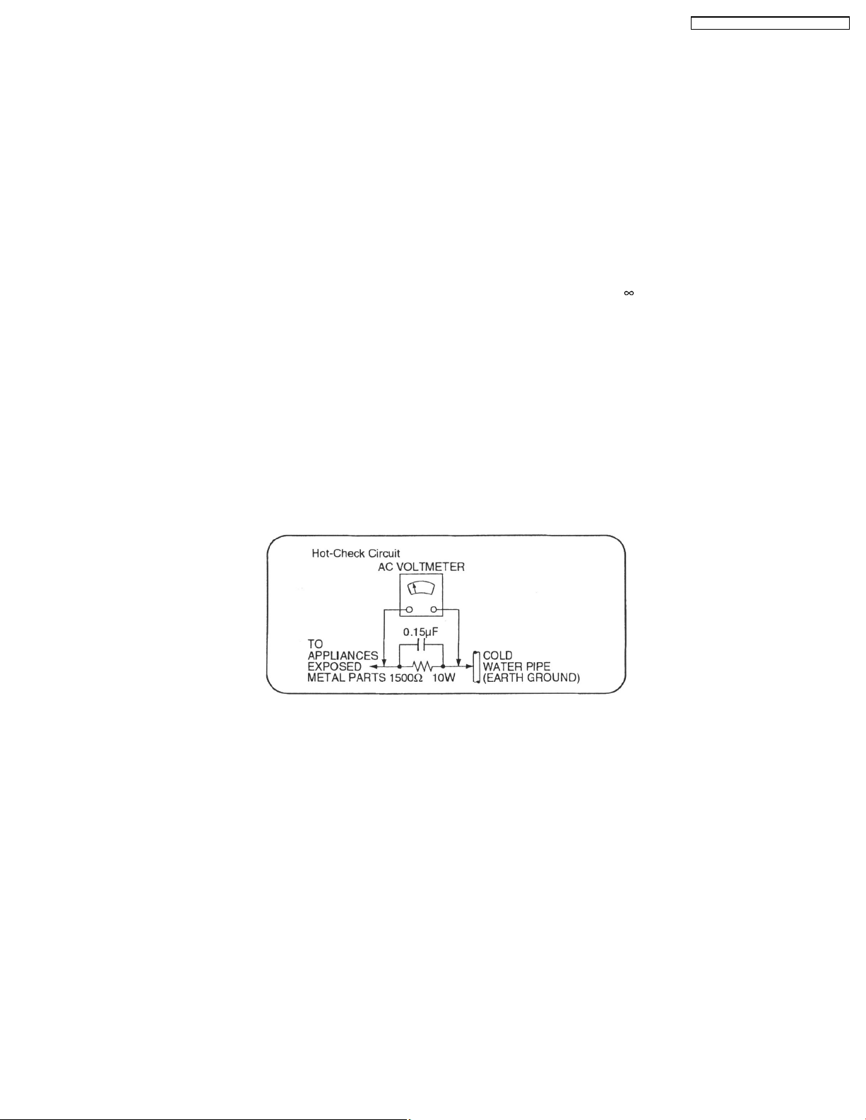
1.1.2. LEAKAGE CURRENT HOT CHECK (See Figure 1.)
1. Plug the AC cord directly into the AC outlet. Do not use an isolation transformer for this check.
2. Connect a 1.5kΩ, 10 watts resistor, in parallel with a 0.15µF capacitors, between each exposed metallic part on the set and a
good earth ground such as a water pipe, as shown in Figure 1.
3. Use an AC voltmeter, with 1000 ohms/volt or more sensitivity, to measure the potential across the resistor.
4. Check each exposed metallic part, and measure the voltage at each point.
5. Reverse the AC plug in the AC outlet and repeat each of the above measurements.
6. The potential at any point should not exceed 0.75 volts RMS. A leakage current tester (Simpson Model 229 or equivalent) may
be used to make the hot checks, leakage current must not exceed 1/2 milliamp. should the measurement is outside of the limits
specified, there is a possibility of a shock hazard, and the equipment should be repaired and re-checked before it is returned
to the customer.
.
Figure. 1
3

SA-PM46E / SA-PM46EG / SA-PM46EF
1.2. Before Repair and Adjustment
Disconnect AC power, discharge Power Supply Capacitors C501, C502, C602, C910, C911, C915 and C923 through a 10Ω,1W
resistor to ground.
DO NOT SHORT-CIRCUIT DIRECTLY (with a screwdriver blade, for instance), as this may destroy solid state devices.
After repairs are completed, restore power gradually using a variac, to avoid overcurrent.
• Current consumption at AC 230V, 50 Hz in NO SIGNAL mode (volume min) should be ~150 mA.
1.3. Protection Circuitry
The protection circuitry may have operated if either of the following conditions are noticed:
• No sound is heard when the power is turned on.
• Sound stops during a performance.
The function of this circuitry is to prevent circuitry damage if, for example, the positive and negative speaker connection wires are
"shorted", or if speaker systems with an impedance less than the indicated rated impedance of the amplifier are used.
If this occurs, follow the procedure outlines below:
1. Turn off the power.
2. Determine the cause of the problem and correct it.
3. Turn on the power once again after one minute.
Note:
When the protection circuitry functions, the unit will not operate unless the power is first turned off and then on again.
1.4. Safety Part Information
Safety Parts List:
There are special components used in this equipment which are important for safety.These parts are marked by
Schematic Diagrams & Replacement Parts List. It is essential that these critical partsshould be replaced with manufacturer’s
specified parts to prevent shock, fire or other hazards. Do not modify the original designwithout permission of manufacturer.
Table 1
Reference No. Part No. Part Name & Description Remarks
A2 K2CQ2CA00007 AC CORD [M]E/EG
A2 K2CQ2CA00002 AC CORD [M]EF
F1 K5D631BLA012 FUSE [M]
JK600 K2AA2B000017 JK AC INLET [M]
T600 G4CYAYY00137 SUB TRANSFORMER [M]
T601 G4CYAYY00139 MAIN TRANSFO RMER [M]
L600 G0B371HA0005 LINE FILTER [M]
Z600 ERZV10V511CS ZENER [M]
RL600 K6B1AEA0 0015 POWER RELAY [M]
FP352 K5G502A00039 FUSE PROTECTOR [M]
FP601 K5G502A00039 FUSE PROTECTOR [M]
FP950 K5G102AA0002 FUSE PROTECTOR [M]
R441 ERD2FCVG330T RESISTOR (33 1/4W) [M]
R608 ERD2FCVG120T RESISTOR (12 1/4W) [M]
R753 D0AF100JA039 RESISTOR (10 1/2W) [M]
27 RKSV0037G-K REAR CABINET [M]
PCB4 REPX0669A TRANSFORMER P.C.B. [M] (RTL)
301 RAE0165Z-V TRAVERSE UNIT (W/O SERVO P.C.B) [M] (RTL)
in the
4

SA-PM46E / SA-PM46EG / SA-PM46EF
2 Prevention of Electro Static Discharge (ESD) to
Electrostatically Sensitive (ES) Devices
Some semiconductor (solid state) devices can be damaged easily by electricity. Such components commonly are called
Electrostatically Sensitive (ES) Devices. Examples of typical ES devices are integrated circuits and some field-effect transistors and
semiconductor “chip” components. The following techniques should be used to help reduce the incidence of component damage
caused by electro static discharge (ESD).
1. Immediately before handlin g any semiconducto r component or semiconductor-equiped assembly, drain off any ESD on your
body by touching a known earth ground. Alternatively, obtain and wear a commercially available discharging ESD wrist strap,
which should be removed for potential shock reasons prior to applying power to the unit under test.
2. After removing an electrical assembly equiped with ES devices, place the assembly on a conductive surface such as aluminium
foil, to prevent electrostatic charge build up or exposure of the assembly.
3. Use only a grounded-tip soldering iron to solder or unsolder ES devices.
4. Use only an anti-static solder removal device. Some solder removal devices not classified as “anti-static (ESD protected)” can
generate electrical charge to damage ES devices.
5. Do not use freon-propelled chemicals. These can generate electrical charges sufficie nt to damage ES devices.
6. Do not remove a replacement ES device from its protective package until immediately before you are ready to install it. (Most
replacement ES devices are packaged with leads electrically shorted together by conductive foam, aluminium foil or
comparable conduc tive material).
7. Immediately before removing the protective material from the leads of a replacement ES device, touch the protective material
to the chassis or circuit assembly into which the device will be installe d.
Caution
Be sure no power is applied to the chassis or circuit, and observe all other safety precautions.
8. Minimize bodily motions when handling unpackaged replacement ES devices. (Otherwise harmless motion such as the
brushing together of your clothes fabric or the lifting of your foot from a carpeted floor can generate static electricity (ESD)
sufficient to damage an ES device).
5

SA-PM46E / SA-PM46EG / SA-PM46EF
3 Precaution of Laser Diode
Caution :
This product utilizes a laser diode with the unit turned "ON", invisible laser radiation is emitted from the pick up lens.
Wavelength : 785 nm
Maximum output radiation power from pick up : 100 µW/VDE
Laser radiation from pick up unit is safety level, but be sure the followings:
1. Do not disassemble the optical pick up unit, since radiation from exposed laser diode is dangerous.
2. Do not adjust the variable resistor on the pick up unit. It was already adjusted.
3. Do not look at the focus lens using optical instruments.
4. Recommend not to look at pick up lens for a long time.
ACHTUNG :
Dieses Produkt enthält eine Laserdiode. Im eingeschalteten Zustand wird unsichtbare Laserstrahlung von der Lasereinheit
abgestrahlt.
Wellenlänge : 785nm
Maximale Strahlungsleistung der Lasereinheit :100 µW/VDE
Die Strahlung an der Lasereinheit ist ungefä hrlich, wenn folgende Punkte beachtet werden:
1. Die Lasereinheit nicht zerlegen, da die Strahlung an der freigelegten Laserdiode gefährlich ist.
2. Den werkseitig justierten Einstellregler der Lasereinhit nicht verstellen.
3. Nicht mit optischen Instrumenten in die Fokussierlinse blicken.
4. Nicht über längere Zeit in die Fokussierlinse blicken.
ADVARSEL :
I dette a apparat anvendes laser.
CAUTION!
THIS PRODUCT UTILIZES A LASER.
USE OF CONTROLS OR ADJUSTMENTS OR PERFORMANCE OF PROCEDURES OTHER THAN THOSE SPECIFIED HEREIN MAY RESULT
IN HAZARDOUS RADIATION EXPOSURE.
I Use of Caution Labels
6
SA-PM46E / SA-PM46EG / SA-PM46EF
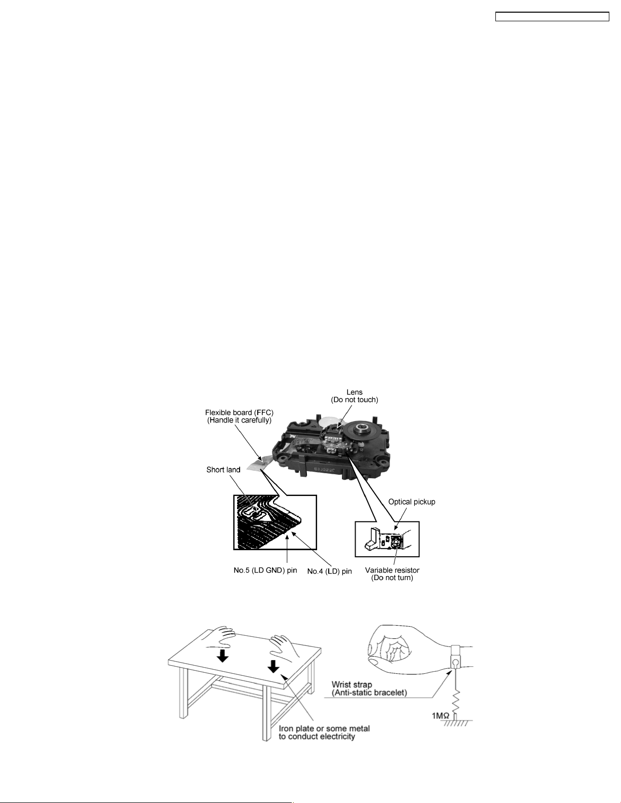
4 Handling Precautions For Traverse Deck
The laser diode in the traverse deck (optical pickup) may break down due to potential difference caused by static electricity of
clothes or human body. So, be careful of electrostatic breakdown during repair of the traverse deck (optical pickup).
• Handling of traverse deck (optical pickup)
1. Do not subject the traverse deck (optical pickup) to static electricity as it is extremely sensitive to electrical shock.
2. To prevent the breakdown of the laser diode, an antistatic shorting pin is inserted into the flexible board (FFC board).
3. Take care not to apply excessive stress to the flexible board (FFC board). When removing or connecting the short pin, finish
the job in as short time as possible. (Fig 4.1)
4. Do not turn the variable resistor (laser power adjustment). It has already been adjusted.
• Grounding for electrostatic breakdown prevention
1. Work table grounding. (Fig 4.2)
Use the anti-static wrist strap to discharge the static electricity from your body.
2. Work table grounding. (Fig 4.2)
Put a conductive material (sheet) or steel sheet on the area where the traverse deck (optical pickup) is place, and ground
the sheet.
Caution:
The static electricity of your clothes will not be grounded through the wrist strap. So, take care not to let your clothes touch the
traverse deck (optical pickup).
Caution when replacing the Traverse Deck
The traverse deck has a short point shorted with solder to protect the laser diode against electrostatics breakdown. Be sure to
remove the solder from the short point before making connections.
(Fig 4.1)
(Fig 4.2)
7
SA-PM46E / SA-PM46EG / SA-PM46EF
5 Handling the Lead free Solder
5.1. General description about Lead Free Solder (PbF)
The lead free solder has been used in the mounting process of all electrical components on the printed circuit boards used for this
equipment in considering the globally environmental conservation.
The normal solder is the alloy of tin (Sn) and lead (Pb). On the other hand, the lead free solder is the alloy mainly consists of tin
(Sn), silver (Ag) and Copper (Cu), and the melting point of the lead free solder is higher approx.30 degrees C (86°F) more than that
of the normal solder.
Definition of PCB Lead Free Solder being used
The letter of “PbF” is printed either foil side or components side on the PCB using the lead free solder.
(See right figure)
Service caution for repair work using Lead Free Solder (PbF)
• The lead free solder has to be used when repairing the equipment for which the lead free solder is used.
(Definition: The letter of “PbF” is printed on the PCB using the lead free solder.)
• To put lead free solder, it should be well molten and mixed with the original lead free solder.
• Remove the remaining lead free solder on the PCB cleanly for soldering of the new IC.
• Since the melting point of the lead free solder is higher than that of the normal lead solder, it takes the longer time to melt
the lead free solder.
• Use the soldering iron (more than 70W) equipped with the temperature control after setting the temperature at 350±30
degrees C (662±86°F).
Recommended Lead Free Solder (Service Parts Route.)
• The following 3 types of lead free solder are available through the service parts route.
RFKZ03D01K-----------(0.3mm 100g Reel)
RFKZ06D01K-----------(0.6mm 100g Reel)
RFKZ10D01K-----------(1.0mm 100g Reel)
Note
* Ingredient: Tin (Sn), 96.5%, Silver (Ag) 3.0%, Copper (Cu) 0.5%, Cobalt (Co) / Germanium (Ge) 0.1 to 0.3%
8
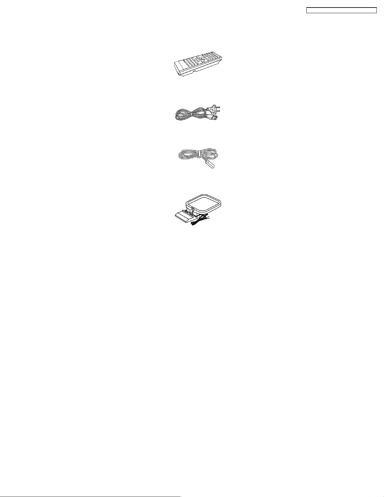
6 Accessories
Note : Refer to Packin g Materials & Accessories Parts List (Section 22) for the part number.
Remote Control
AC Cord
FM Antenna
SA-PM46E / SA-PM46EG / SA-PM46EF
AM Loop Antenna
9
SA-PM46E / SA-PM46EG / SA-PM46EF
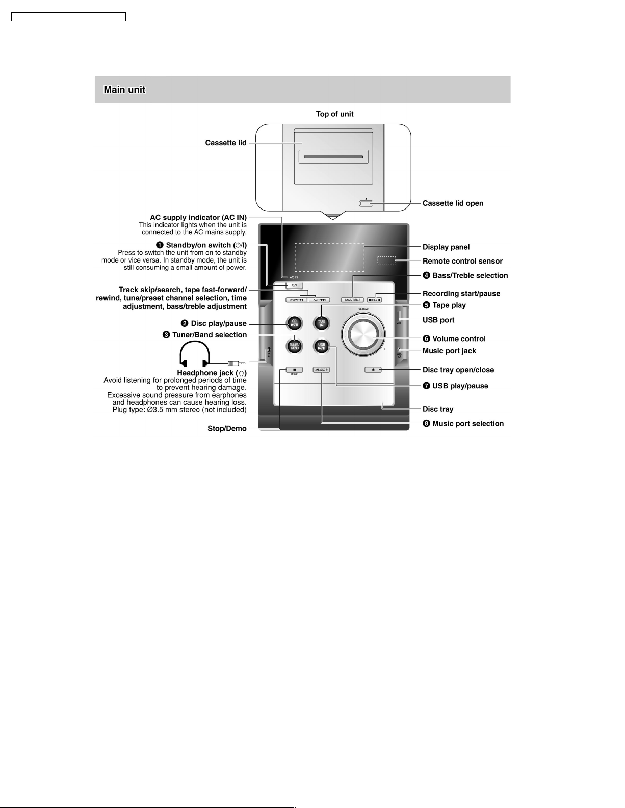
7 Operation Procedures
7.1. Main Unit Key Buttons Operation
10
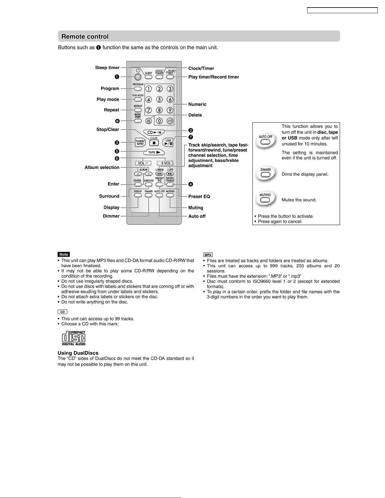
7.2. Remote Control Key Buttons Operation
SA-PM46E / SA-PM46EG / SA-PM46EF
7.3. Disc Information
11
SA-PM46E / SA-PM46EG / SA-PM46EF
8 Self diagnosis and special mode setting
This unit is equipped with features of self-diagnostic & special mode setting for checking the functions & reliability.
8.1. Service Mode Summary Table
The service modes can be activated by pressing various button combination on the main unit and remote control unit.Below is the
summary for the various modes for checking:
Player buttons Remote control unit buttons Application Note
[STOP] [4], [7] To enter into doctor mode (Refer to the section 8.2. for more
Mode Remote control unit buttons Application Note
In Doctor Mode [DIMMER] FL ALL Segment inspection (Refer to section 8.2. service mode Table 1
[4] CD to Tape Recording Test Mode (Refer to section 8.2. service mode Table 1
[5] Tape Recording and Playing (Refer to section 8.2. service mode Table 1
[6] CD and Tape Eject test (Refer to section 8.2. service mode Table 1
[7] Volume 50 setting check (Refer to section 8.2. service mode Table 1
[8] Volume 29 setting check (Refer to section 8.2. service mode Table 1
[9] Volume 0 setting check (Refer to section 8.2. service mode Table 1
[ ], [1], [1] CD Loading Test Mode (Refer to section 8.2. service mode Table 1
[ ], [1], [2] CD Traverse Unit Test Mode (Refer to section 8.2. service mode Table 1
[ ], [1], [3] CD Combination Test Mode (Refer to section 8.2. service mode Table 1
[ ], [1], [4] CD Auto Adjustment Display (Refer to section 8.2. service mode Table 1
[SLEEP] Cold Start Setting (Refer to section 8.2. service mode Table 1
information.)
& 2 for more information.)
& 2 for more information.)
& 2 for more information.)
& 2 for more information.)
& 2 for more information.)
& 2 for more information.)
& 2 for more information.)
& 2 for more information.)
& 2 for more information.)
& 2 for more information.)
& 2 for more information.)
& 2 for more information.)
8.2. Service Mode Table
Below is the various special modes for checking:-
8.2.1. Service Mode Table 1
Item FL Display Key Operation
Mode Name Description Front Key
Self -Diagnostic
Mode
To enter into self
diagnostic checking for
main unit.
1. Select [ ] for CD mode (Ensure no
2. Press and hold [
To exit, press
remote control.
tape or CD inserted).
seconds follow by [
button on main unit or
]button for 2
].
12
Item FL Display Key Operation
Mode Name Description Front Key
Doctor Mode To enter into Doctor
Mode for checking of
various items and
displaying EEPROM and
firmware version.
Note: The microprocessor version as
shown is an example. It
will be revise when there
is an updates.
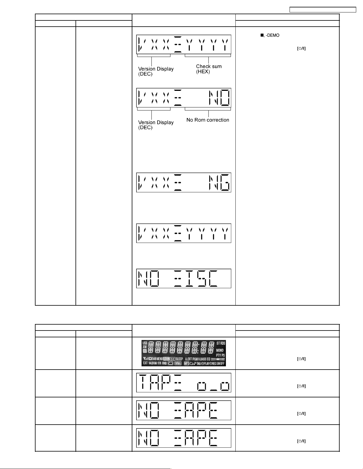
FL Display
sequenceDisplay 1 → 2
(a) If there is NO EEPROM header string
OR
(b) If there is no EEPROM ( no data is
received by micro-processor) [NO] is
displayed.
(Display 1)
Checksum : (Condition 1)
Checksum : (Condition 2)
In any mode:
1. Press [
To exit Doctor Mode, press
main unit or remote control.
SA-PM46E / SA-PM46EG / SA-PM46EF
] button on main unit follow
by [4] and [7] on remote control.
button on
If the version of the EEPROM does not
match or not working properly [NG] is
display.
Checksum : (Condition 3)
If the EEPROM version matches, checksum
[YYYY] is displayed.
(Display 2)
The Check Sum of EEPROM and firmware
version will be display for 2 sec.
8.2.2. Service Mode Table 2
Item FL Display Key Operation
Mode Name Description Front Key
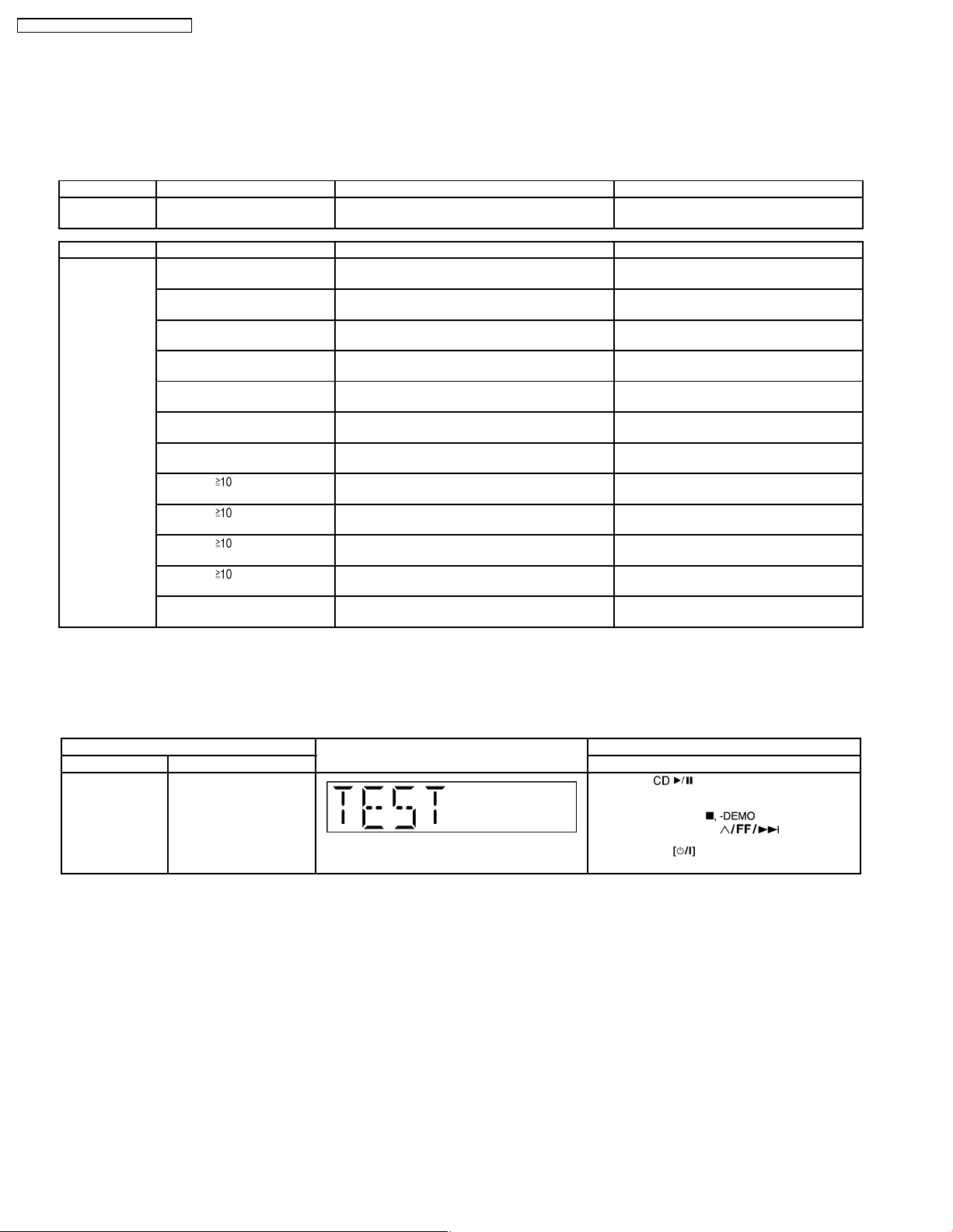
FL Display Test To check the FL
CD to Tape
Recording Test
Mode
Tape Recording
and Playing
CD Open and
Tape Eject Test
Mode
segments display (All
segments will light up)
To Inspect the recording
process from CD to
TAPE for the unit.
(For more information,
refer to section 8.2.3)
To Inspect the Tape
recording and playing is
process for unit.
(For more information,
refer to section 8.2.4)
To check on the CD
Open and Tape Eject
function.
In doctor mode:
1. Press [DIMMER] button on remote control.
To cancel, press [0] button on remote control.
To exit Doctor Mode, press
main unit or remote control.
In doctor mode:
1. Press [4] button on remote control.
To exit Doctor Mode, press
main unit or remote control.
In doctor mode:
1. Press [5] button on remote control.
To exit Doctor Mode, press
main unit or remote control.
In doctor mode:
1. Press [6] button on remote control.
To exit Doctor Mode, press
main unit or remote control.
button on
button on
button on
button on
13

SA-PM46E / SA-PM46EG / SA-PM46EF
Item FL Display Key Operation
Mode Name Description Front Key
Volume Setting
Mode
To check for the volume
setting of the main unit.
The volume will be
automatically set to its
respective level (in dB).
During this mode,
treble/bass/EQ will be set
to ‘0’dB & OFF.
Display 1 In doctor mode:
1. Press [7] button on remote control.
To exit Doctor Mode, press
main unit or remote control.
Display 1 In doctor mode:
2. Press [8] button on remote control.
To exit Doctor Mode, press
main unit or remote control.
button on
button on
CD Loading Test
Mode
CD Traverse Unit
Test Mode
To determine the
reliability of CD Loading
Unit.
To check for the
open/close operation for
the CD loading unit. It
fails when there is
abnormality in opening or
closing.
To check for the traverse
unit operation. In this
made, the first & lost
track is access & read
(TOC). It fails when TOC
is not completed by IDS
or the traverse is out of
focus.
Display 1 In doctor mode:
3. Press [9] button on remote control.
To exit Doctor Mode, press
main unit or remote control.
In doctor Mode:
1. Press [
control.
To cancel, press [0] button on remote control.
To exit Doctor Mode, press
main unit or remote control.
In doctor Mode:
1. Press [
control.
To cancel, press [0] button on remote control.
To exit Doctor Mode, press
main unit or remote control.
button on
], [1] & [1] button on remote
button on
], [1] & [2] button on remote
button on
CD Combination
Test Mode
A combination of CD
loading & Traverse unit
test.
CD Auto
Adjustment
Display
To display result of selfadjustment for CD.
(For more information,
refer to section 8.2.5)
TPS To check FF TPS for
deck.
(For more information,
refer to section 8.2.6)
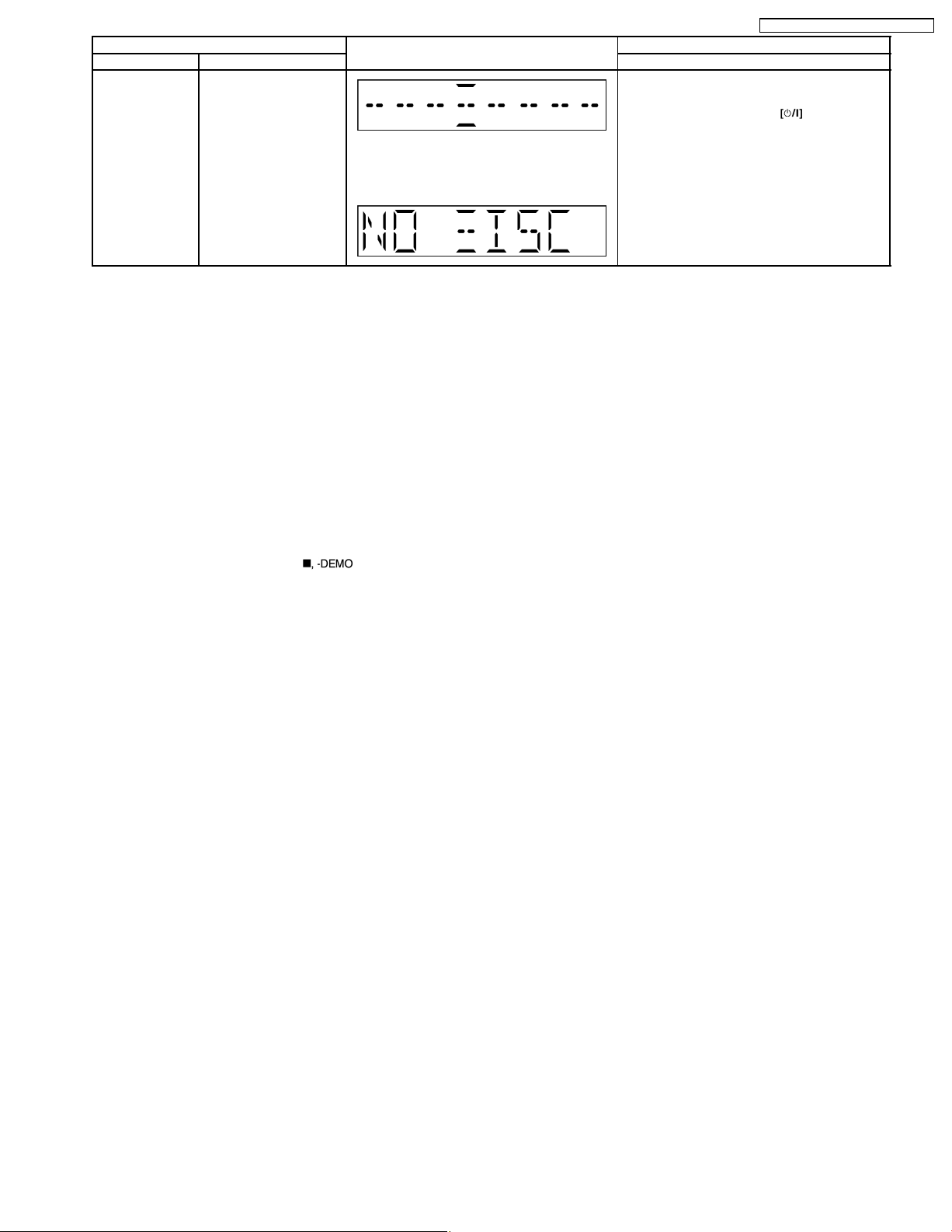
The [NO DISC] display will appear after 3 sec.
In doctor Mode:
1. Press [
], [1] & [3] button on remote
control.
To cancel, press [0] button on remote control.
To exit Doctor Mode, press
button on
main unit or remote control.
In doctor mode:
1. Press [
], [1] & [4] button on remote
control.
To exit Doctor Mode, press
button on
main unit or remote control.
In doctor mode:
1. Press [
] button on remote
control.
To cancel, press [0] button on remote control.
To exit Doctor Mode, press
button on
main unit or remote control.
14
SA-PM46E / SA-PM46EG / SA-PM46EF
Item FL Display Key Operation
Mode Name Description Front Key
Cold Start To activate cold start
ipon next AC power up.
Note: This test do not work when selector is in
Tuner.
The [NO DISC] display will appear after 3 sec.
In doctor mode:
1. Press [SLEEP] button on remote control.
To exit Doctor Mode, press
main unit or remote control.
button on
8.2.3. CD to Tape Recording Inspection
Purpose : To check the recording function from CD to Tape.
Below is the procedures for this mode:-
Step 1: Enter into Doctor mode (For more information refer to section 8.2 on key operation to enter into this mode).
Step 2: Insert Test disc (CDT-018). Note: Ensure TOC is completed before next step.
Step 3: Press [4] button on remote control. (It enter into CD to Tape Test mode. The volume is set to [50dB], Bass & Treble is set
to 0dB & EQ is switch off).
Note : When in this mode, the following processes is perform :
a) Deck will rewind to the start point (point at the start of recording) & stop.
b) Recording begins (at constant analogue recording speed) for 3 seconds & stop.
• However, “Error” would be display if there is no tracks to access to, no tape inserted, no test CD inserted or when the tape
erasure prevention tab for FWD side is not suitable for recording.
• To exit from this mode, press [
] button on main uint.
8.2.4. Tape Recording and Playing
Purpose : To check the tape operating function. (Playability & record function)
Note:
Below is the procedures for this mode:-
Step 1: Enter into Doctor mode (For more information refer to section 8.2 on key operation to enter into this mode).
Step 2: Press [5] button on remote control. (During this mode, tape function is set to automatically, volume is set to [50dB], Bass
& Treble is set to 0dB & EQ is switch off).
Step 3: The tape played for 3 seconds after which it stop & eject. (Cassette door opens automatically)
Note : When in CD to Tape Recording Test mode, the following process is perform :
a) If the erasure prevention tab for FWD side the tape is broken, it is judged as an error and the recording operation does not start.
b) If tape stops by detecting a tape end while recording, it becomes an error.
c) If STOP key is pressed while recording or playing , the operation shall be terminated by stopping TAPE. In this case, the doctor
mode is not released.
d) DMT is output with the same timing as usual.
15

SA-PM46E / SA-PM46EG / SA-PM46EF
8.2.5. CD Self-Adjustment (AJST) Result Display
Purpose : To display the result of self-adjustment for CD.
Below is the procedures for this mode:-
Step 1: Enter into Doctor mode (For more information refer to section 8.2 on key operation to enter into this mode).
Step 2 : When [
correspond to the condition met as shown in the table below :
], [1] & [4] key are pressed at the doctor mode, the following shall be displayed for 3 secs. The result shall
8.2.6. TPS Inspection
Purpose : Tape for TPS is put into Deck. TPS inspection starts with one key operation. This mode shall run a test program to check
16
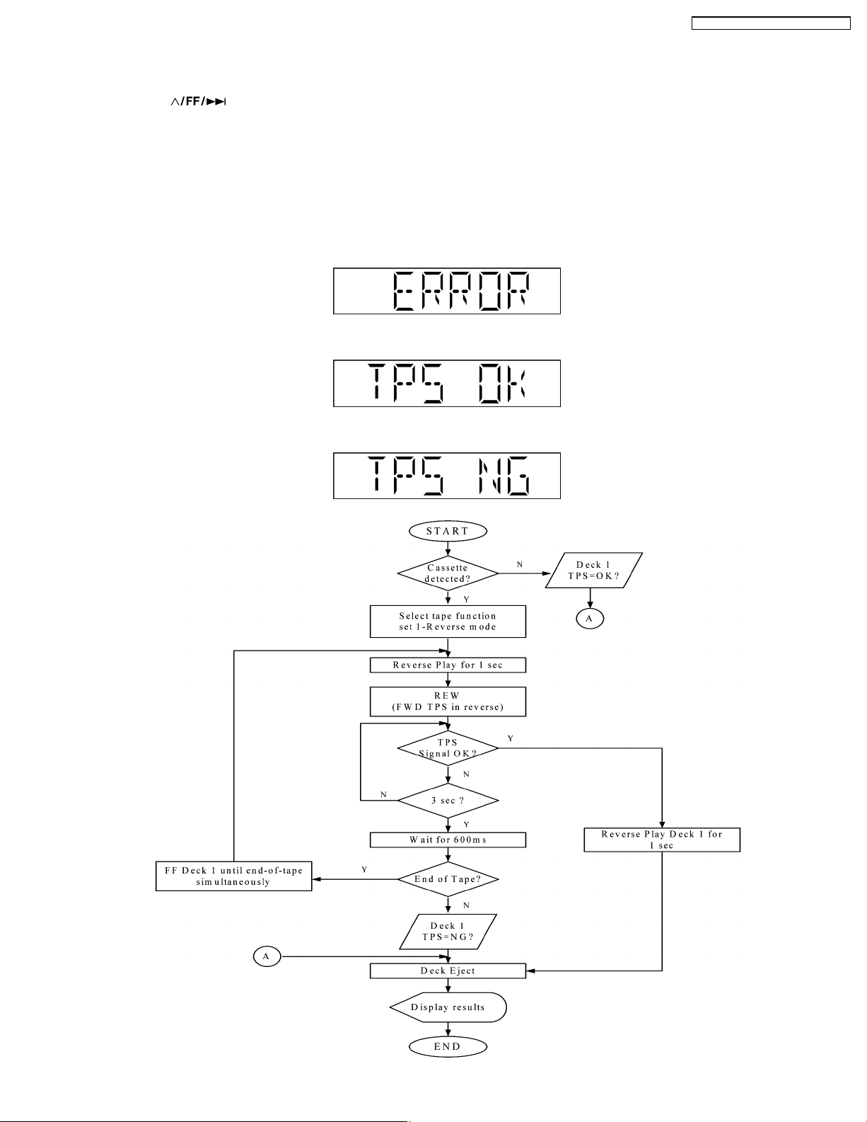
SA-PM46E / SA-PM46EG / SA-PM46EF
REV TPS for the Deck and ends by displaying the result and ejecting the Deck.
Below is the procedures for this mode:-
Step 1: Enter into Doctor mode (For more information refer to section 8.2 on key operation to enter into this mode).
Step 2 : Press [
] button on remote control. (It enters into TPS Test mode).
The following process is carry out in this test mode.
Micro-processor will start checking for the existence of cassette in deck mechanism unit, -
• If it does not contain any cassette, it shall end the test and displays [ERROR].
• If the cassette is detected, test shall start by playing the DECK in reverse direction for 1 sec and perform REV TPS.
• If TPS signal is OK, the Deck shall be ejected. Below is information on the TPS under 3 examples.
1. If ERROR Flag is set "ERROR" shall be display ed. TPS check result shall not be shown in this case.
2. If Deck TPS check = OK
3. If Deck TPS check = NG
17
SA-PM46E / SA-PM46EG / SA-PM46EF
8.3. Cassette Mechanism Self-Diagnostic Mode
Below is information of the checking of cassette deck mechanism
No. Operation Procedures Micon operation & processing
1 C-mecha Abnormal Detection shall be
executed for DECK.
2 [ ] key is pressed, after loading in a
NORMAL type cassette with the recording tab
on the left side removed.
3 [ ] key is pressed, after loading a
NORMAL, CrO2, METAL type cassette with
the recording tab on the right side removed.
4 [TAPE ] Key is pressed, after loading in a
NORMAL, CrO2, METAL type cassette (
cassette for TPS checking purposes and with
both recording tabs intact ).
5 [REC] key is pressed, after loading in a
NORMAL type cassette ( with both recording
tabs intact )
6 Self-diagnostic mode is stopped by pressing
the [I] Key.
7 To clear all the abnormalities in the memory,
press the [I] Key for more than 5 Sec while
the self-diagnostic mode is stopped.
8 To cancel the self-diagnostic mode press the
Key.
Check that all DECK mechanism leaf SW is in OFF state.
FF shall be executed for 2 sec, after which STOP.
Check the following.
{ F.REC INH SW } is OFF
{ HALF SW } is ON
Reel pulse toggles between H & L.
REW shall be executed for 2 sec, after which STOP.
Check the following.
{ F.REC INH SW } is ON
{ HALF SW } is ON
Reel pulse toggles between H & L.
TPS operation is executed. Check the following.
{ F.REC INH SW } is ON
{ HALF SW } is ON
TPS signal changes.
After checking TPS, it shall STOP.
If TPS checking is completed at TAPE END, it is considered as TPS
abnormal.
REC operation shall not be executed.
Check the following.
{ F.REC INH SW } is ON
{ HALF SW } is ON
LCD shall display the abnormality item code, when the STOP key is pressed,
it shall display the abnormality item code in the following sequence.
[ TEST H 0 1] [ TEST H 0 2] [ TEST H 0 3]
At this time, all the abnormalities item in the memory is cleared and is
displayed on the LCD.[ C L E A R ] display for 1 Sec. then,[ TEST ] is
displayed.
POWER is OFF.At the next POWER ON, normal operation shall be executed.
• If RAM check error occurs during microcomputer reset, COLDSTART shall be executed and all the error memory shall be
cleared during RAM initialization.
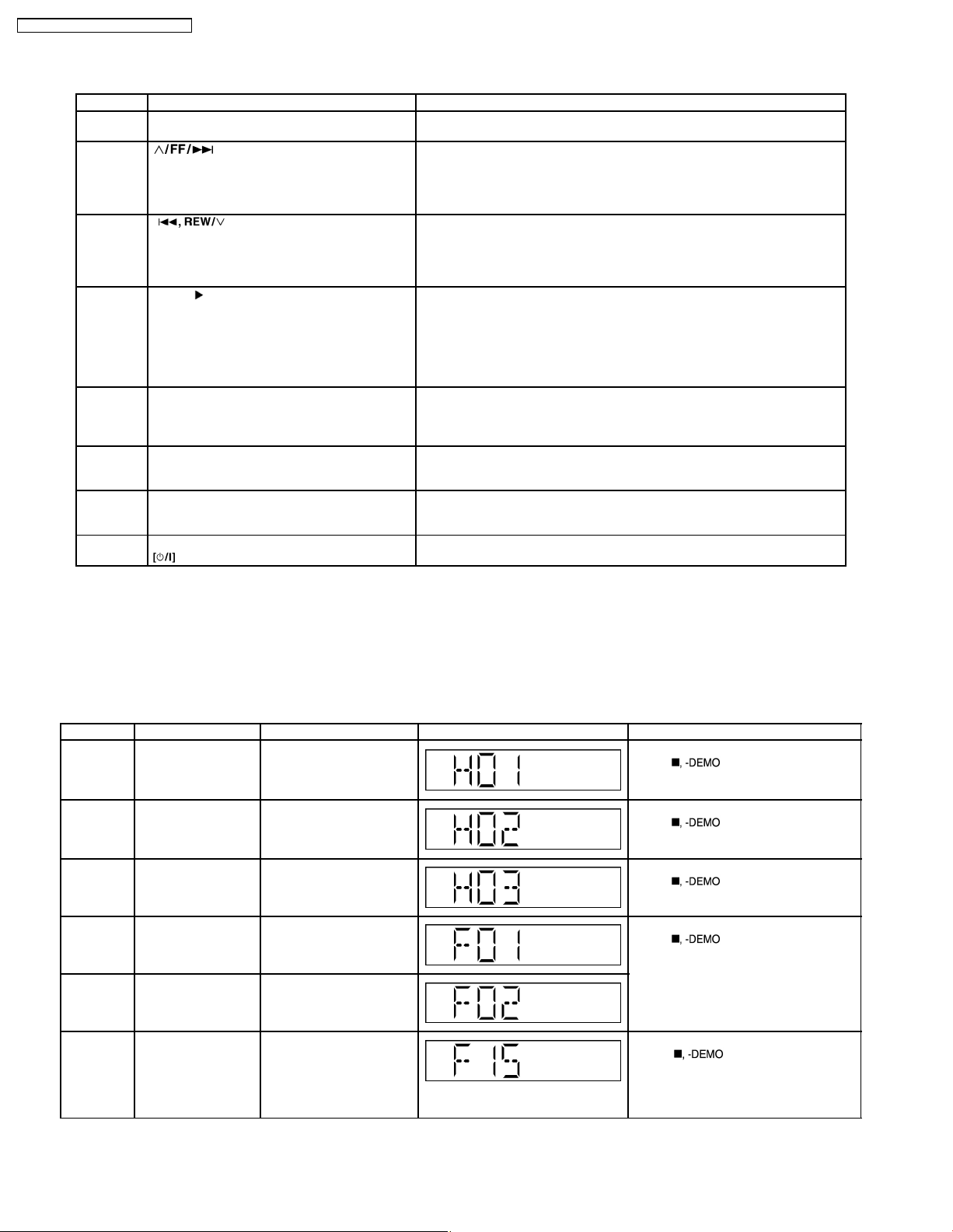
8.4. Error Code Table
Self-Diagnosis Function provides information on any problems occuring for the unit and its respective components by display ing
error codes. Thesed error code such as U**, H** and F** are stored in memory and held unless it is cleared.
The error code is automatically display after entering into self-diagnostic mode.
Error Code Diagnosis Contents Description of error Automatic FL Display Remarks
H01 MODE SW abnormal For deck mechanism unit.
H02 REC INH SW
abnormal
H03 HALF SW abnormal For deck mechanism unit.
F01 Reel pulse abnormal For deck mechanism unit.
F02 TPS abnormal
Press [
error.
For deck mechanism unit.
Press [
error.
Press [
error.
Press [
error.
] on main unit for next
] on main unit for next
] on main unit for next
] on main unit for next
F15 CD REST SW
Abnormal
CD traverse position intial
setting operation failsafe
counter (1000 ms) waiting
for REST SW to turn on.
Error No. shall be clear by
force or during cold start.
18
For CD unit (For Traverse).
Press [
error.
] on main unit for next
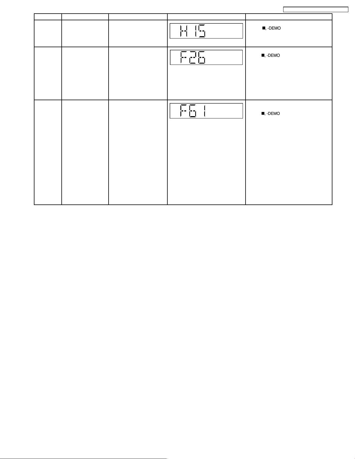
Error Code Diagnosis Contents Description of error Automatic FL Display Remarks
H15 CD OPEN SW
Abnormal
During normal operation
CD OPEN SW ON fail to be
detected with 4 sec. Error
For CD unit (For Traverse).
Press [
error.
No. shall be clear by force
or during cold start.
F26 Communication
between CD servo
LSI and micro-p
abnormal.
CD function DTMS
command, after system
setting, If SENSE = ´L´
cannot be detected.
For CD unit (For Traverse).
Press [
error.
Memory shall contain F26
code. After Power on, CD
function shall continue,
error display shall be "NO
DISC". Error No. shall be
clear by force or cold start.
F61 POWER AMP IC
output abnormal.
During normal operation, if
DCDET becomes "L",
normal POWER OFF
process shall not be
For Power Supply Related Error
Detection.
Press [
error.
executed, PCONT shall be
switched to "L"
immediately. "GOODBYE"
shall not be display but the
error display F61 is
displayed instead. 2
seconds after the F61
displayed, ECONO shall be
set to "L" and FL display
shall be turned off. The
error content shall be
memorized when the
abnormality occurs and can
be display in the C-mecha
self-diagnostic mode
described later.
SA-PM46E / SA-PM46EG / SA-PM46EF
] on main unit for next
] on main unit for next
] on main unit for next
19
SA-PM46E / SA-PM46EG / SA-PM46EF
9 Assembling and Disassembling
9.1. Caution
“ATTENTION SERVICER”
Be careful when disassembling and servicing.
Some chassis components may have sharp edges.
Special Note:
1. This section describes the disassembly procedures for all the major printed circuit boards and main components.
2. Before the disassembly process was carried out, do take special note that all safety precautions are to be carried out.
(Ensure that no AC power supply is connected during disassembling.)
3. For assembly after operation checks or replacement, reverse the respective procedures.
Special reassembly procedures are described only when required.
4. Do take note of the locators on each printed circuit board during reassembling procedures.
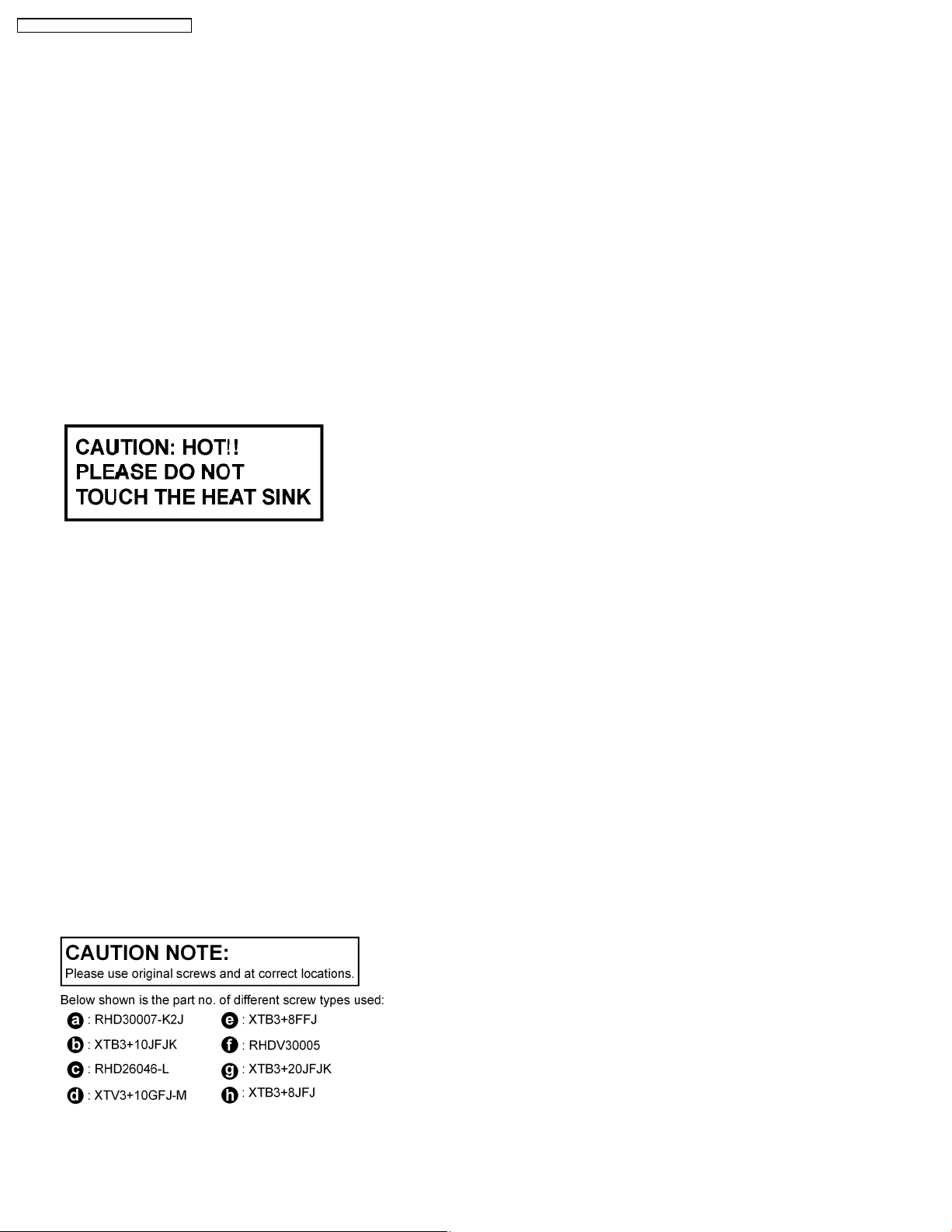
5. The Switch Regulator IC may have high temperature after prolonged use.
6. Use caution when removing the top cabinet and avoid touching heat sinks located in the unit.
7. Select items from the following index when checks or replacement are required.
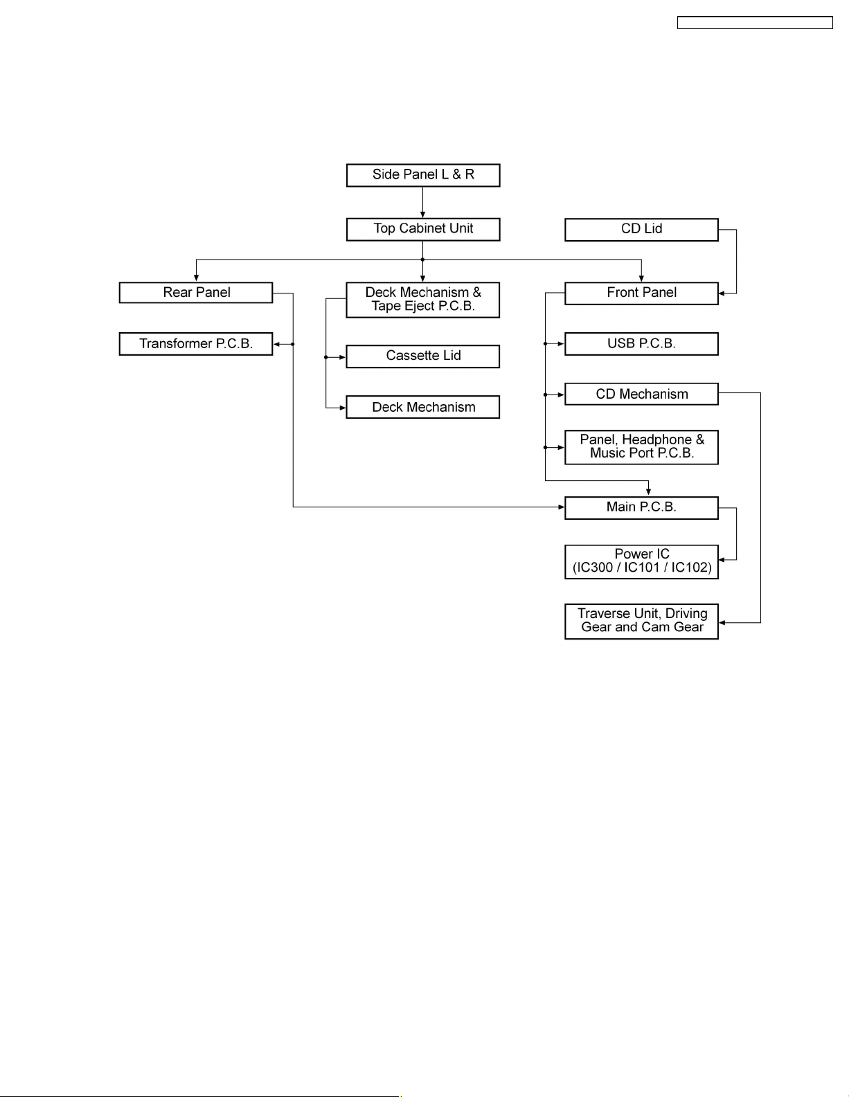
• Disassembly of Side Panel L & R
• Disassembly of Top Cabinet Unit
• Disassembly of Deck Mechanism Unit & Tape Eject P.C.B
• Disassembly of CD Lid
• Disassembly of Front Panel
• Disassembly of USB P.C.B
• Disassembly of Panel P.C.B, Headphone P.C.B and Music Port P.C.B
• Disassembly of Rear Panel
• Disassembly of Main P.C.B
• Replacement of the Power IC
• Disassembly of Transformer P.C.B
• Disassembly of CD Mechanism
• Disassembly of Cassette Lid
• Disassembly of Traverse Unit, Driving Gear and Cam Gear
• Disassembly of Deck Mechanism
• Handling of Cassette Tape Jam
20
SA-PM46E / SA-PM46EG / SA-PM46EF
9.2. Disassembly flow chart
The following chart is the procedure for disassembling the casing and inside parts for internal inspection when carrying out the
servicing.
To assemble the unit, reverse the steps shown in the chart below.
21
SA-PM46E / SA-PM46EG / SA-PM46EF
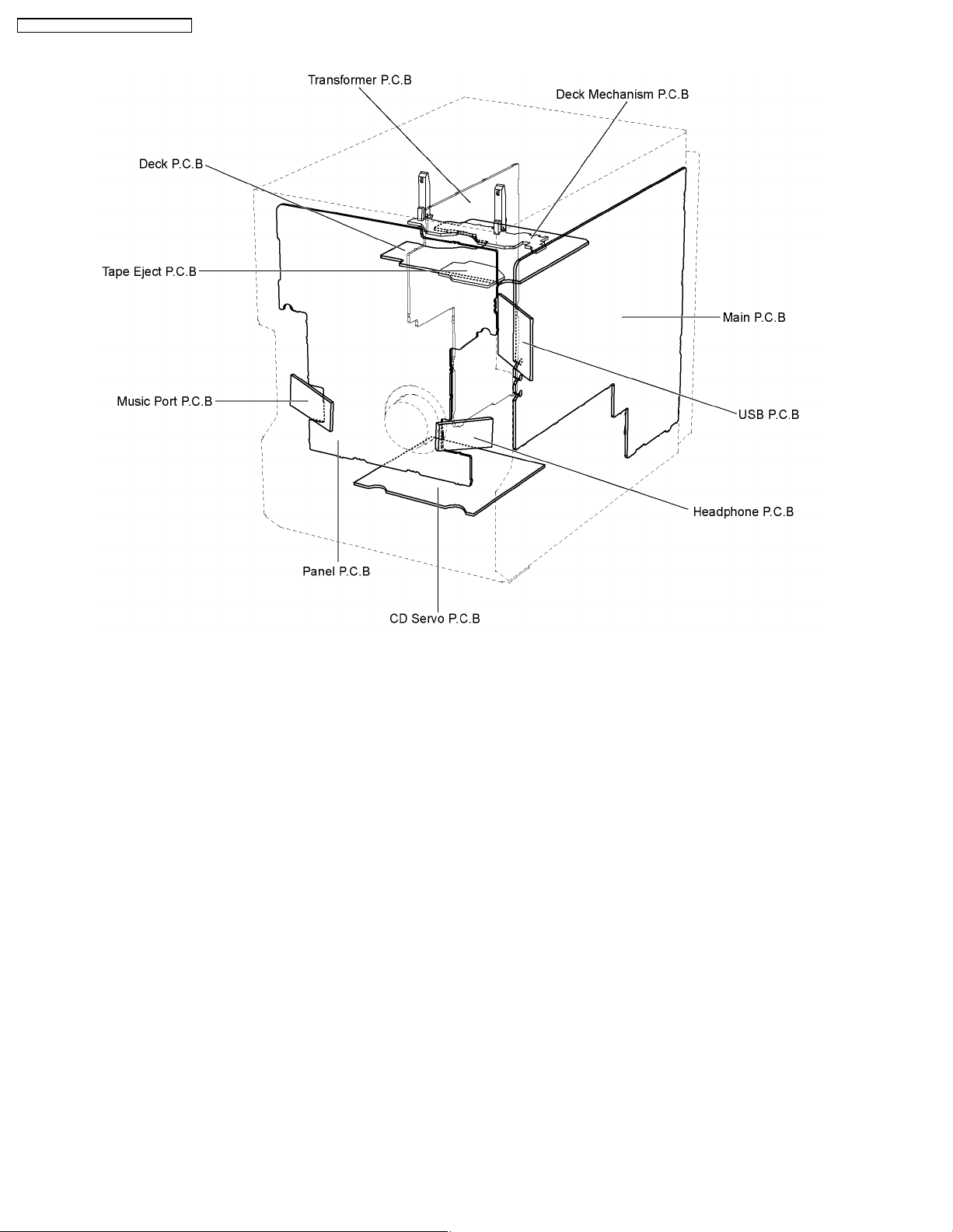
9.3. Main Parts Location Diagram
22
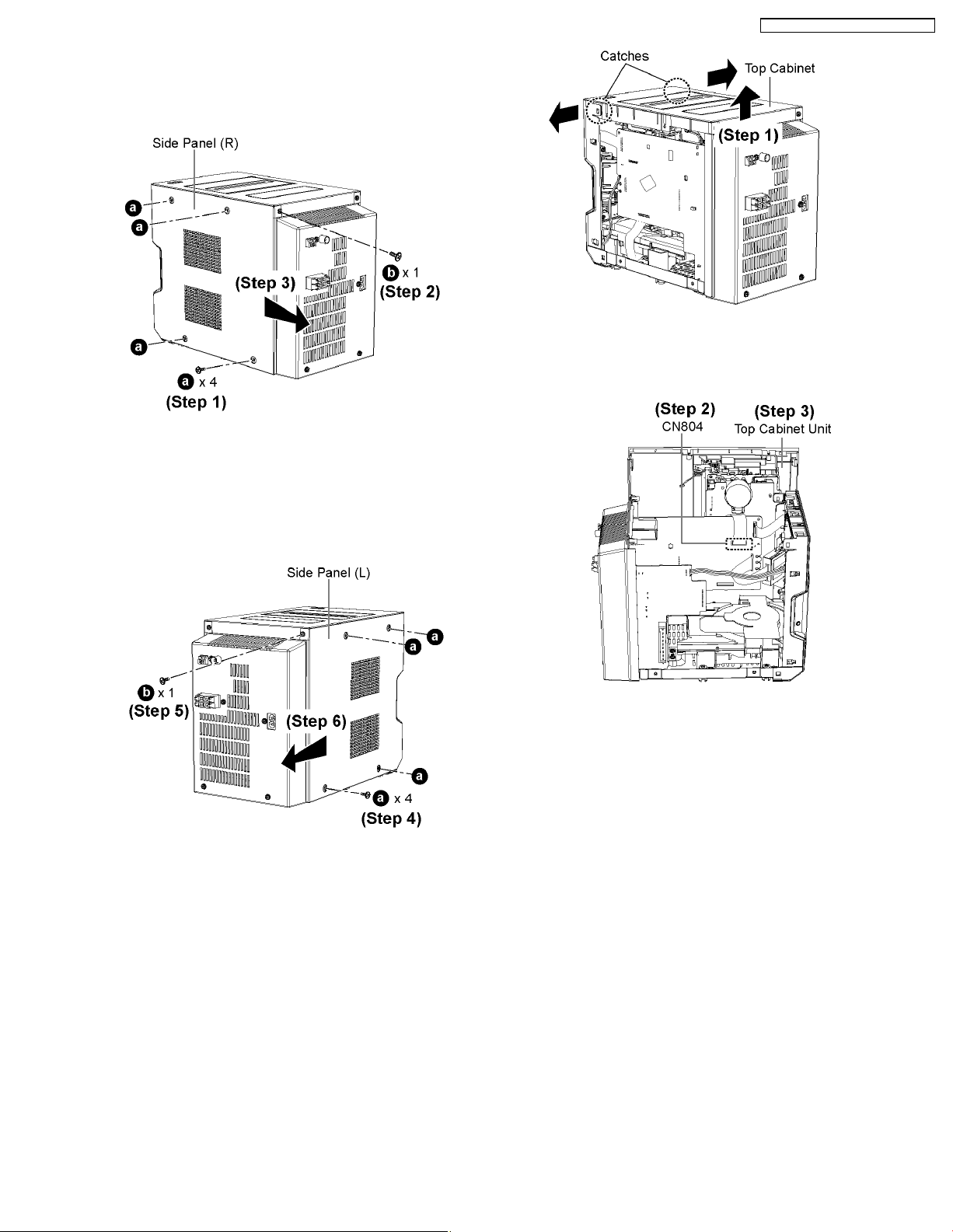
9.4. Disassembly of Side Panel (L /
R)
• Disassembly of Side Panel (R)
Step 1: Remove 4 screws.
Step 2 : Remove 1 screw.
Step 3 : Remove the Side Panel (R) as arrow shown.
SA-PM46E / SA-PM46EG / SA-PM46EF
Step 1 : Lift up the top cabinet as arrow shown.
Note: Be careful of the catches area.
• Disassembly of Side Panel (L)
Step 4: Remove 4 screws.
Step 5 : Remove 1 screw.
Step 6 : Remove the Side Panel (L) as arrow shown.
9.5. Disassembly of Top Cabinet
Unit
Step 2 : Disconnect FFC cable (CN804).
Step 3 : Remove Top Cabinet Unit.
9.6. Disassembly of Deck
Mechanism Unit and Tape
Eject P.C.B
• Follow the (Step 1) - (Step 6) of Item 9.4.
• Follow the (Step 1) - (Step 3) of Item 9.5.
• Diasssembly of Tape Eject P.C.B
• Follow the (Step 1) - (Step 6) of Item 9.4.
23

SA-PM46E / SA-PM46EG / SA-PM46EF
Step 1 : Remove 1 screw.
Step 2 : Release the clutch.
Step 3 : Remove the Tape Eject P.C.B.
• Disassembly of Deck Mechanism Unit
Step 1 : Connect the AC power cord.
Step 2 : Press the POWER button to power up the main unit.
Step 3 : Press the OPEN/CLOSE button, the disc tray will open
automatically.
Step 4 : Remove 4 screws
Step 5 : Push the lever as arrow shown to open the Cassette
Lid.
Step 6 : Remove the Deck Mechanism Unit.
9.7. Disassembly of CD Lid
• Follow the (Step 1) - (Step 6) of Item 9.4.
• Follow the (Step 1) - (Step 3) of Item 9.5.
When opening the disc tray automatically (Using Power
Supply)
Step 4 : Release the 2 claws.
Step 5 : Remove the CD Lid as arrow shown.
Step 6 : Press the OPEN/CLOSE button, the disc tray will
24
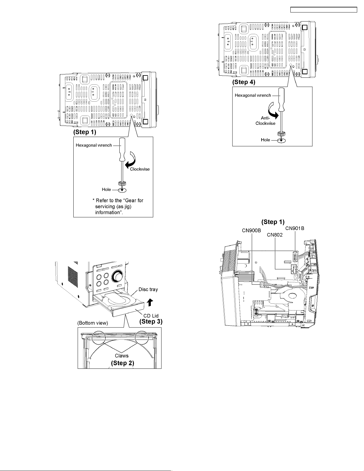
close.
[Open the disc tray manually (Using service tools)]
Note: This method applies if failure to power up the unit for
the opening of tray.
SA-PM46E / SA-PM46EG / SA-PM46EF
Step 4 : Repeat Step 1 but rotate the gear tools in anticlockwise
9.8. Disassembly of Front Panel
Step 1 : Insert the gear tool into the hole on the underside of
CD chassis and then rotate in the direction of arrow. The disc
tray will be open.
• Follow the (Step 1) - (Step 6) of Item 9.4.
• Follow the (Step 1) - (Step 3) of Item 9.5.
• Follow the (Step 1) - (Step 6) of Item 9.7.
Step 1 : Detach wire cable (CN802, CN900B and CN901B).
Step 2 : Release the 2 claws.
Step 3 : Remove the CD Lid as arrow shown.
• To close the CD tray.
25
SA-PM46E / SA-PM46EG / SA-PM46EF
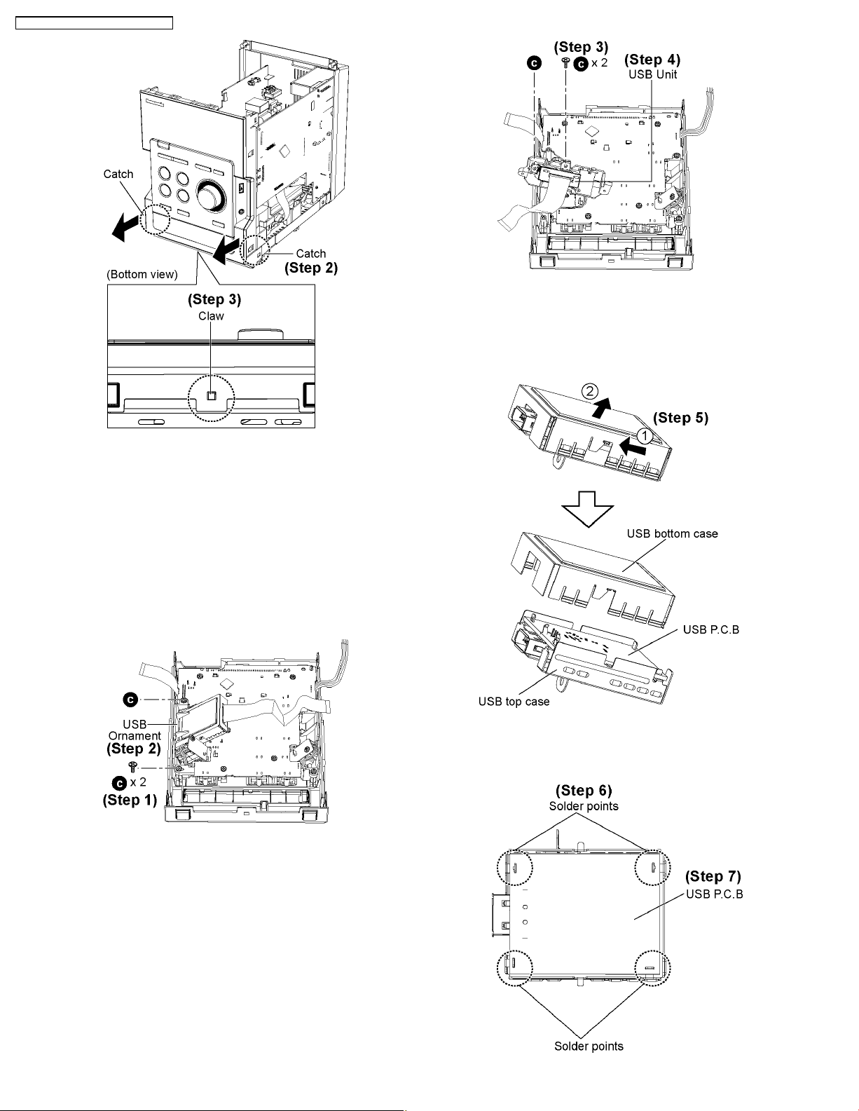
Step 3 : Remove 2 screws.
Step 4 : Remove USB Unit.
Step 2 : Release 2 catches.
Step 3 : Release the claw at the bottom cabinet and remove the
Front Panel as arrow shown.
9.9. Disassembly of USB P.C.B
• Follow the (Step 1) - (Step 6) of Item 9.4.
• Follow the (Step 1) - (Step 3) of Item 9.5.
• Follow the (Step 1) - (Step 6) of Item 9.7.
• Follow the (Step 1) - (Step 3) of Item 9.8.
Step 1 : Remove 2 screws.
Step 2 : Remove the USB Ornament.
Step 5 : Remove USB bottom case as arrow shown.
26
Step 6 : Unsolder 4 points.
Step 7 : Remove USB P.C.B.
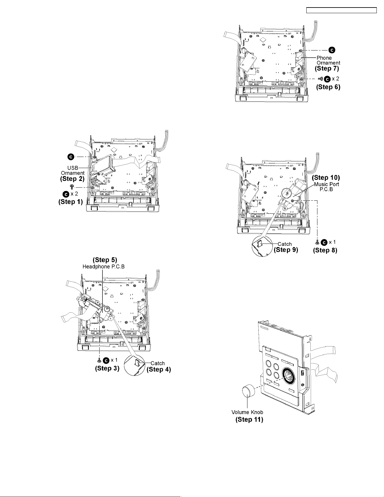
9.10. Disassembly of Panel P.C.B,
Headphone P.C.B & Music
Port P.C.B
• Follow the (Step 1) - (Step 6) of Item 9.4.
• Follow the (Step 1) - (Step 3) of Item 9.5.
• Follow the (Step 1) - (Step 6) of Item 9.7.
• Follow the (Step 1) - (Step 3) of Item 9.8.
SA-PM46E / SA-PM46EG / SA-PM46EF
• Disassembly of Headphone P.C.B
Step 1 : Remove 2 screws.
Step 2 : Remove the USB Ornament.
Step 6 : Remove 2 screws.
Step 7 : Remove the Phone Ornament.
Step 8 : Remove 1 screw.
Step 9 : Release the catch.
Step 10 : Remove the Music Port P.C.B.
Step 3 : Remove 1 screw.
Step 4 : Release the catch.
Step 5 : Remove the Headphone P.C.B.
• Disassembly of Music Port P.C.B
• Disassembly of Panel P.C.B
Step 11 : Remove the Volume Knob.
27
 Loading...