

Panasonic SAPM-42-EG, SAPM-42-EP, SAPM-42-EF Service manual
CD Stereo System
Model No. SA-PM42EG
SA-PM42EF
SA-PM42EP
Product Color: (K)...Black T ype
PSG1002016CE
Notes: Please refer to the Original Service Manual for :
O CD Mechanism Unit (DLS6C), Order No. MD0803034CE
O Speaker system SB-PM48EG-K, Order No . PSG0902008CE
TA BLE OF CONTENTS
PAGE PAGE
1 Safety Precautions----------------------------------------------- 3
1.1. General Guidelines---------------------------------------- 3
1.2. Before Repair and Adjustment------------------------- 4
1.3. Protection Circuitry---------------------------------------- 4
1.4. Safety Part Information----------------------------------- 4
2 Warning-------------------------------------------------------------- 5
2.1. Prevention of Electro Static Discharge (ESD)
to Electrostatically Sensitive (ES) Devices---------- 5
2.2. Precaution of Laser Diode------------------------------- 6
2.3. Service caution based on Legal restrictions-------- 7
2.4. Handling Precaution for Traverse Unit--------------- 8
3 Service Navigation ---------------------------------------------10
3.1. Service Information--------------------------------------10
4 Specifications---------------------------------------------------- 11
5 Location of Controls and Components------------------ 12
5.1. Main Unit Key Button Operations-------------------- 12
5.2. Remote Control Key Button Operations------------ 13
5.3. Media Information---------------------------------------- 14
6 Self-diagnostic and special mode setting-------------- 15
6.1. Entering into Self-diagnostic Mode------------------15
6.2. Self-diagnostic Function Error Code ----------------15
6.3. Entering into Doctor Mode-----------------------------16
© Panasonic Corporation 2010. All rights reserved.
Unauthorized copying and distribution is a violation of
law.

7 Troubleshooting Guide----------------------------------------20
8 Service Fixture & Tools---------------------------------------21
9 Disassembly and Assembly Instructions---------------22
9.1. Disassembly flow chart ---------------------------------23
9.2. Main Parts Location Diagram -------------------------24
9.3. Disassembly of Top Cabinet Assembly------------- 25
9.4. Disassembly of Headphone P.C.B.------------------26
9.5. Disassembly of iPod P.C.B.----------------------------27
9.6. Disassembly of iPod Lid--------------------------------27
9.7. Disassembly of Front Panel Assembly -------------32
9.8. Disassembly of USB P.C.B. ---------------------------33
9.9. Disassembly of Panel P.C.B.--------------------------34
9.10. Disassembly of FL Window----------------------------35
9.1 1 . Disassembly of Centre Ornament -------------------36
9.12. Disassembly of CD Lid----------------------------------36
9.13. Disassembly of CD Mechanism Unit (DLS6C) ---38
9.14. Disassembly of Power P.C.B.-------------------------38
9.15. Replacement of Power Amp IC (IC5101)---------- 40
9.16. Disassembly of Main P.C.B.---------------------------42
9.17. Disassembly of Fan Unit -------------------------------44
9.18. Disassembly of Transformer P.C.B. -----------------45
9.19. Replacement of Transistor (Q5901)-----------------46
9.20. Disassembly of CD Servo P.C.B.--------------------- 48
10 Disassembly and Assembly of Traverse Unit ---------50
10.1. Disassembling Procedures ----------------------------50
10.2. Assembling Procedure----------------------------------51
11 Service Position -------------------------------------------------53
11.1. Checking & Repairing USB P.C.B.-------------------53
11.2. Checking & Repairing Panel P.C.B. -----------------55
11.3. Checking & Repairing CD Servo P.C.B.------------56
11.4. Checking & Repairing Power P.C.B. ----------------57
11.5. Checking & Repairing Transformer P.C.B.---------58
11.6. Checking & Repairing Main P.C.B. ------------------60
12 Vo ltage Measurement & Waveform Chart--------------- 61
12.1. CD SERVO P.C.B. ---------------------------------------61
12.2. USB P.C.B.-------------------------------------------------62
12.3. MAIN P.C.B. (1/2) ----------------------------------------63
12.4. MAIN P.C.B. (2/2) ----------------------------------------64
12.5. PANEL P.C.B.---------------------------------------------64
12.6. POWER P.C.B. -------------------------------------------64
12.7. TRANSFORMER P.C.B.--------------------------------65
12.8. Waveform Chart------------------------------------------66
13 Illustration of IC’s, Transistors and Diodes ------------ 67
14 Overall Simplified Block--------------------------------------69
15 Block Diagram ---------------------------------------------------70
15.1. SERVO/SYSTEM CONTROL BLOCK
DIAGRAM--------------------------------------------------70
15.2. AUDIO BLOCK DIAGRAM ----------------------------71
15.3. POWER SUPPLY BLOCK DIAGRAM--------------72
16 Wiring Connection Diagram---------------------------------73
17 Schematic Diagram Notes -----------------------------------75
18 Schematic Diagram---------------------------------------------77
18.1. CD SERVO CIRCUIT -----------------------------------77
18.2. MAIN CIRCUIT (1/4) ------------------------------------78
18.3. MAIN CIRCUIT (2/4) ------------------------------------79
18.4. MAIN CIRCUIT (3/4) ------------------------------------80
18.5. MAIN CIRCUIT (4/4) ------------------------------------81
18.6. PANEL CIRCUIT and HEADPHONE CIRCUIT---82
18.7. USB CIRCUIT---------------------------------------------83
18.8. iPod CIRCUIT and POWER CIRCUIT--------------84
18.9. TRANSFORMER CIRCUIT----------------------------85
19 Printed Circuit Board------------------------------------------ 87
19.1. CD SERVO P.C.B. and TRANSFORMER
P.C.B. ------------------------------------------------------- 87
19.2. MAIN P.C.B.----------------------------------------------- 88
19.3. PANEL P.C.B., HEADPHONE P.C.B. and
POWER P.C.B.------------------------------------------- 89
19.4. iPod P.C.B. and USB P.C.B. -------------------------- 90
20 Terminal Function of IC’s------------------------------------ 91
20.1. IC7001 (MN6627954AMA) IC SERVO
PROCESSOR -------------------------------------------- 91
20.2. IC7002 (BA5948FPE2) IC 4CH Drive-------------- 92
20.3. IC800 (RFKWMPM38EG) IC MICROPROCESSOR -------------------------------------------- 92
21 Exploded View and Replacement Parts List----------- 95
21.1. Exploded View and Mechanical replacement
Parts List--------------------------------------------------- 95
21.2. Electrical Replacement Parts List ------------------- 99
2
1 Safety Precautions
1.1. General Guidelines
1. When servicing, observe the original lead dress. If a short circuit is found, re place all parts which have been overheated or
damaged by the short circuit.
2. After servicing, see to it that all the protective devices such as insulation barriers, insulation papers shields are properly
installed.
3. After servicing, carry out the following leakage current checks to prevent the customer from being exposed to shock hazards.
1.1.1. Leakage Current Cold Check
1. Unplug the AC cord and connect a jumper between the two prongs on the plug.
2. measure the resistance value, with an ohmmeter between the jumpered AC plug a nd each exposed metallic cabinet part on
the equipment such as screwheads, connectors, control shafts, etc. When the exposed metallic part has a return path to th e
chassis, the reading should be between 1MΩ and 5.2MΩ. Whe n the exposed me tal does not have a retu rn path to the chas-
sis, the reading must be
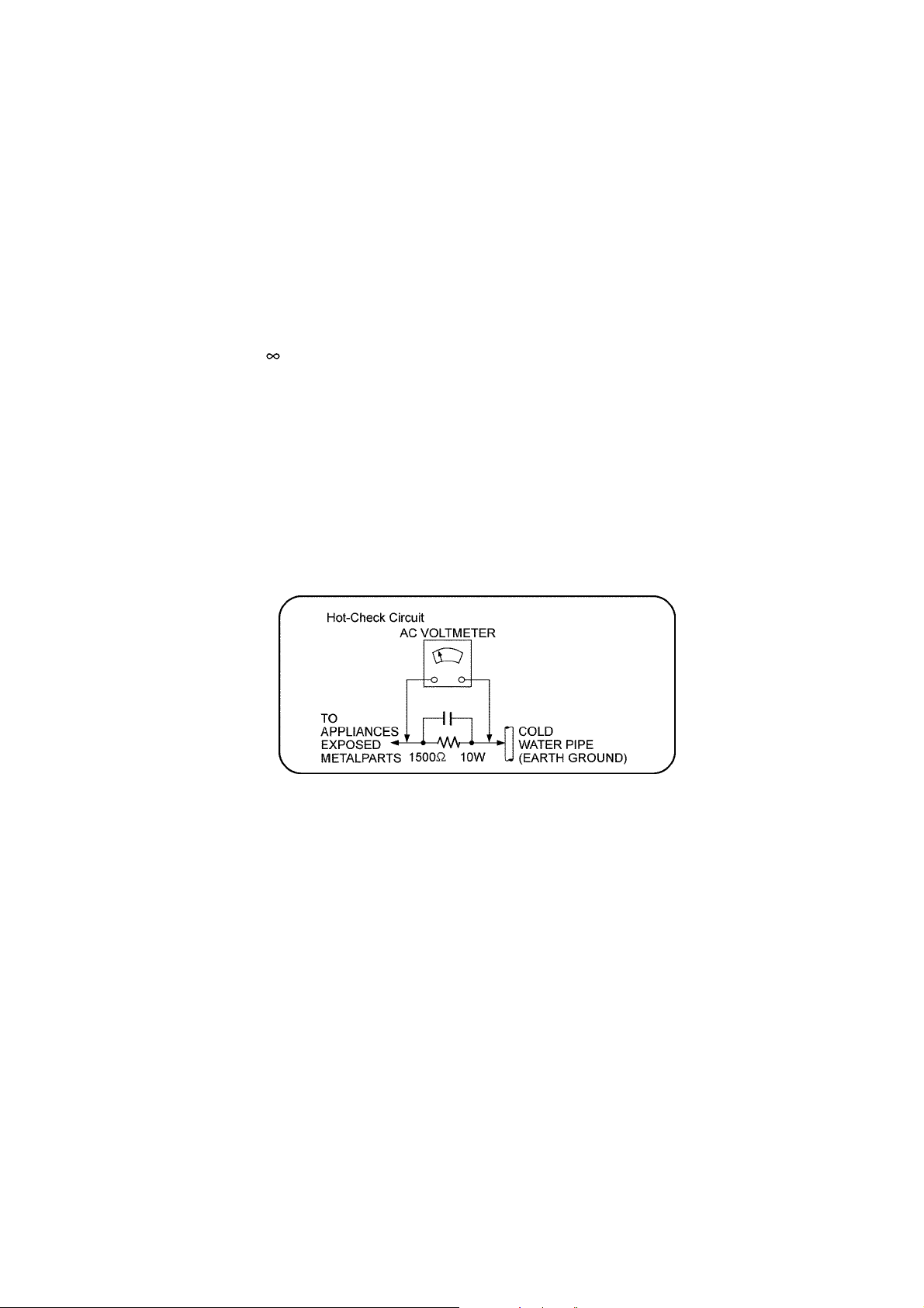
1.1.2. Leakage Current Hot Check
1. Plug the AC cord directly into the AC outlet. Do not use an isolation transformer for this check.
2. Connect a 1.5kΩ, 10 watts resistor, in parallel with a 0.15μF capacitors, between each exposed metallic part on the set and a
good earth ground such as a water pipe, as shown in Figure 1.
3. Use an AC voltmeter, with 1000 ohms/volt or more sensitivity, to measure the potential across the resistor.
4. Check each exposed metallic part, and measure the voltage at each point.
5. Reverse the AC plug in the AC outlet and repeat each of the above measurements.
6. The potential at any point should not exceed 0.75 volts RMS. A leakage current tester (Simpson Model 229 or e quivalent)
may be used to make the hot checks, leakage current must not exceed 1/2 milliamp. In case a measurement is outside of the
limits specified, there is a possibility of a shock hazard, and the equipment sho uld be repaired and rechecked before it is
returned to the customer.
Figure. 1
3
1.2. Before Repair and Adjustment
Caution : DO NOT SHORT-CIRCUIT DIRECTLY (with a screwdriver blade, for instance), as this may destroy solid state devices.
After repairs are completed, restore power gradually using a variac, to avoid overcurrent.
• Current consumption at AC 220-240V, at 50Hz in NO SIGNAL mode (at volume min in FM Tuner mode) should be ~150 mA.
1.3. Protection Circuitry
The protection circuitry may have operated if either of the following conditions are noticed:
• No sound is heard when the power is turned on.
• Sound stops during a performance.
The function of this circuitry is to prevent circuitry damage if, for example, the positive and negative speaker connection wir es are
"shorted", or if speaker systems with an impedance less than the indicated rated impedance of the amplifier are used.
If this occurs, follow the procedure outlines below:
1. Turn off the power.
2. Determine the cause of the problem and correct it.
3. Turn on the power once again after one minute.
Note:
When the protection circuitry functions, the unit will not operate unless the power is first turned off and then on again.
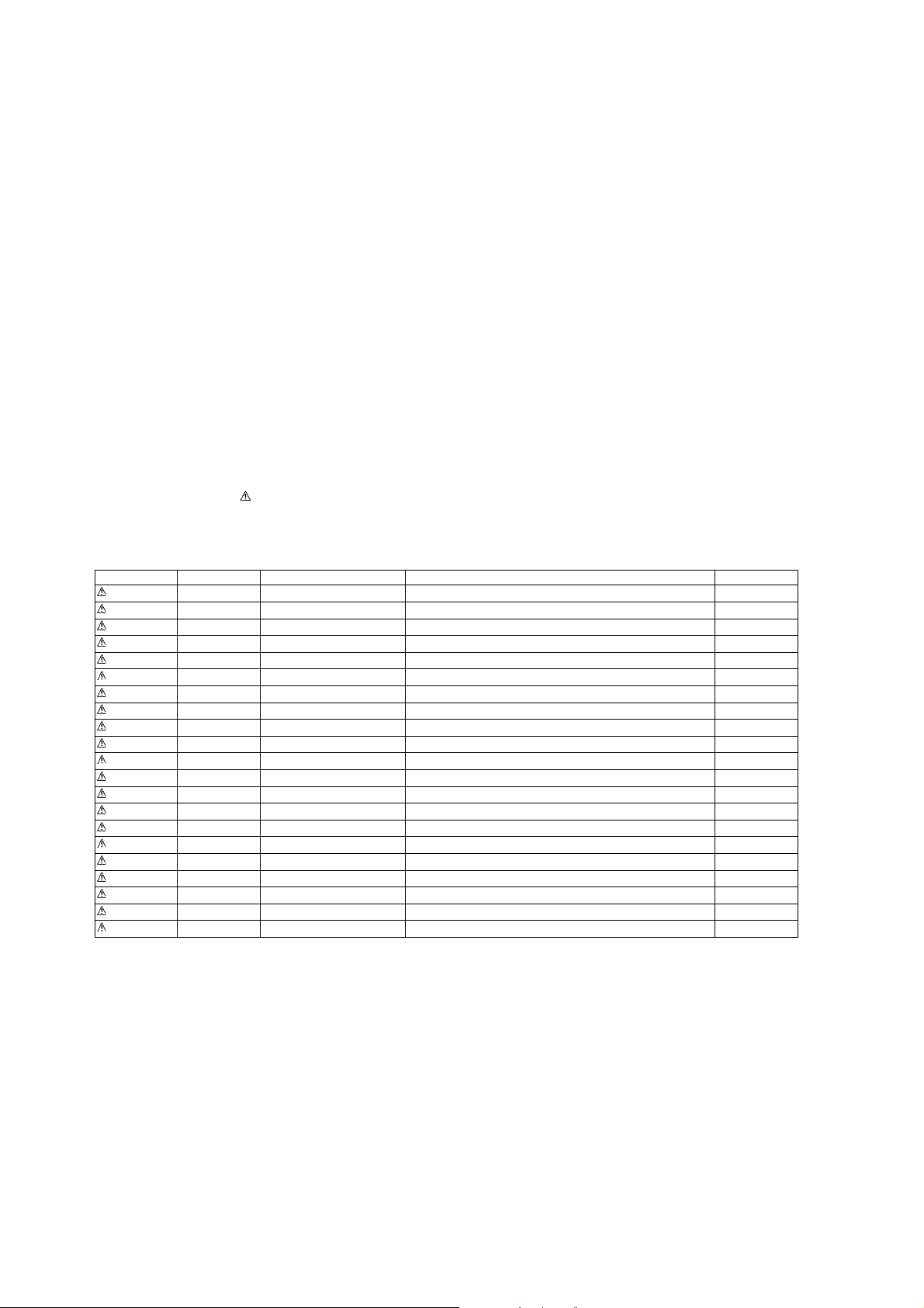
1.4. Safety Part Information
Safety Parts List:
There are special components used in this equipment which are important for safety.
These parts are marked by in the Schematic Diagrams, Exploded View & Replacemen t Parts List. It is essential that these
critical parts should be replaced with manufacturer’s specified parts to prevent shock, fire or other hazards. Do not modify the
original design without permission of manufacturer.
Table 1
Safety Ref. No. Part No. Part Name & Description Remarks
L5901 ELF15N035AN LINE FILTER
T5901 G4CYBYY00022 TRANSFORMER
T5902 G4C2AAJ00005 BACK UP TRANSFORMER
Z5901 ERZVA5Z471 ZENER
RL5901 K6B1AEA00003 POWER RELAY
F5901 K5D102BLA013 FUSE
FP5901 K5G502AA0002 FUSE PROTECTOR
JK5901 K2AA2B000011 AC INLET
R260 ERD2FCVG470T 47 1/4W
R5905 ERD2FCVG120T 12 1/4W
PCB2 REPX0849HA TRANSFORMER P.C.B. (RTL)
401 RAEX0190Z-V TRAVERSE UNIT
22 RFKHAPM42EGK REAR CABINET ASS’Y EG
22 RFKHAPM42EPK REAR CABINET ASS’Y EP
22 RFKHAPM42EFK REAR CABINET ASS’Y EF
A2 K2CQ2CA00007 AC CORD
A3 RQTX0186-2D O/I BOOK (Ge/It/Fr/Sp) EF
A3 RQTX0187-2H O/I BOOK (Du/Da/Sw) EG
A3 RQTX0188-2E O/I BOOK (Po/Cz/Ar) EP
A3 RQTX0189-2R O/I BOOK (Ru/Ur) EP
A3 RQTX0191-2B O/I BOOK (En) EP
4

2Warning
2.1. Prevention of Electro Static Discharge (ESD) to Electrostatically Sensitive (ES) Devices
Some semiconductor (solid state) devices can be damaged easily by static electricity. Such components commonly are called Electrostatically Sensitive (ES) Devices. Examples of typical ES devices are integrated circuits and some field-effect transistors and
semiconductor “chip” components. The following techniques should be used to help reduce the incidence of component damag e
caused by electrostatic discharge (ESD).
1. Immediately before handling any semiconductor component or semiconductor-equiped assembly, drain off any ESD on your
body by touching a known earth ground. Alternatively, obtain and wear a commercially available discharging ESD wrist strap,
which should be removed for potential shock reasons prior to applying power to the unit under test.
2. After removing an electrical assembly equiped with ES devices, place the asse mbly on a co nductive su rfa ce such as alum inium foil, to prevent electrostatic charge build up or exposure of the assembly.
3. Use only a grounded-tip soldering iron to solder or unsolder ES devices.
4. Use only an anti-static solder remover device. Some solder removal devices not classified as “anti-static (ESD protected)” can
generate electrical charge sufficient to damage ES devices.
5. Do not use freon-propelled chemicals. These can generate electrical charges sufficient to damage ES devices.
6. Do not remove a replacement ES device from its protective package until immediately before you are ready to install it. (Most
replacement ES devices are packaged with leads electrically shorted together by conductive foam, aluminium foil or comparable conductive material).
7. Immediately before removing the protective material from the leads of a replacement ES device, touch the protective material
to the chassis or circuit assembly into which the device will be installed.
Caution :
Be sure no power is applied to the chassis or circuit, and observe all other safety precautions.
8. Minimize bodily motions when handling unpackaged replacement ES devices. (Otherwise harmless motion such as the
brushing together of your clothes fabric or the lifting of your foot from a carpeted floor can generate static electricity (ESD) suf-
ficient to damage an ES device).
5

2.2. Precaution of Laser Diode
CAUTION!
THIS PRODUCT UTILIZES A LASER.
USE OF CONTROLS OR ADJUSTMENTS OR PERFORMANCE OF PROCEDURES OTHER THAN THOSE SPECIFIED HEREIN MAY RESULT
IN HAZARDOUS RADIATION EXPOSURE.
Caution:
This product utilizes a laser diode with the unit turned "on", invisible laser radiation is emitted from the pickup lens.
Wavelength: 785 nm (CD)
Maximum output radiation power from pick up: 100 μW/VDE
Laser radiation from the pickup unit is safety level, but be sure the followings:
1. Do not disassemble the pickup unit, since radiation from exposed laser diode is dangero us.
2. Do not adjust the variable resistor on the pickup unit. It was already adjusted.
3. Do not look at the focus lens using optical instruments.
4. Recommend not to look at pickup lens for a long time.
ACHTUNG :
Dieses Produkt enthält eine Laserdiode. Im eingeschalteten Zustand wird unsichtbare Laserstrahlung von der Lasereinheit
abgestrahlt.
Wellenlänge : 785 nm (CD)
Maximale Strahlungsleistung der Lasereinheit :100 μW/VDE
Die Strahlung an der Lasereinheit ist ungefährlich, wenn folgende Punkte beachtet werden:
1. Die Lasereinheit nicht zerlegen, da die Strahlung an der freigelegten Laserdiode gefährlich ist.
2. Den werkseitig justierten Einstellregler der Lasereinhit nicht verstellen.
3. Nicht mit optischen Instrumenten in die Fokussierlinse blicken.
4. Nicht über längere Zeit in die Fokussierlinse blicken .
6

2.3. Service caution based on Legal restrictions
2.3.1. General description about Lead Free Solder (PbF)
The lead free solder has been used in the mounting proce ss of a ll electrical components on the printed circuit board s used for this
equipment in considering the globally environmental conservation.
The normal solder is the alloy of tin (Sn) and lead (Pb). On the other hand, the lead free solder is the alloy mainly consists of tin
(Sn), silver (Ag) and Copper (Cu), and the melting point of the lead free solder is higher approx.30 degrees C (86°F) more than that
of the normal solder.
Definition of PCB Lead Free Solder being used
The letter of “PbF” is printed either foil side or components side on the PCB using the lead free solder.
(See right figure)
Service caution for repair work using Lead Free Solder (PbF)
• The lead free solder has to be used when repairing the equipment for which the lead free solder is used.
(Definition: The letter of “PbF” is printed on the PCB using the lead free solder.)
• To put lead free solder, it should be well molten and mixed with the original lead free solder.
• Remove the remaining lead free solder on the PCB cleanly for soldering of the new IC.
• Since the melting point of the lead free solder is higher than that of the normal lead solder, it takes the longer time to melt the
lead free solder.
• Use the soldering iron (more than 70W) equipped with the temperature control after setting the temperatur e at 350±30 degrees
C (662±86°F).
Recommended Lead Free Solder (Service Parts Route.)
• The following 3 types of lead free solder are available through the service parts route.
RFKZ03D01K-----------(0.3mm 100g Reel)
RFKZ06D01K-----------(0.6mm 100g Reel)
RFKZ10D01K-----------(1.0mm 100g Reel)
Note
* Ingredient: Tin (Sn), 96.5%, Silver (Ag) 3.0%, Copper (Cu) 0.5%, Cobalt (Co) / Germanium (Ge) 0.1 to 0.3%
7

2.4. Handling Precaution for Traverse Unit
The laser diode in the optical pickup uni t may break down d ue to static electricity of clothes or human bod y. Special care must be
taken avoid caution to electrostatic breakdown when servicing and handling the laser diode in the traverse unit.
2.4.1. Cautions to Be Taken in Handling the Optical Pickup Unit
The laser diode in the optical pickup unit may be damaged due to electro static discharge generating from clothes or human body.
Special care must be taken avoid caution to electrostatic discharge damage when servicing the laser diode.
1. Do not give a considerable shock to the optical pickup unit as it has an extremely high-precise structure.
2. To p revent the laser diode from the electrostatic discharge damage, the flexible cable of the optical pickup unit removed
should be short-circuited with a short pin or a clip.
3. The flexible cable may be cut off if an excessive force is applied to it. Use caution when handling the flexible cable.
4. The antistatic FPC is connected to the new optical pickup unit. After replacing th e optical pickup unit and connecting the flexible cable, cut off the antistatic FPC.
2.4.2. Grounding for electrostatic breakdown prevention
Some devices such as the CD player use the optical pickup (laser diode) and the optical pickup will be damaged by static electricity
in the working environment. Proceed servicing works under the working environment where grounding works is completed.
2.4.2.1. Worktable grounding
1. Put a conductive material (sheet) or iron sheet on the area where the optical picku p is placed , and ground the sheet.
8

2.4.2.2. Human body grounding
1. Use the anti-static wrist strap to discharge the static electricity form your body (Figure 2).
Figure 2
9

3 Service Navigation
3.1. Service Information
This service manual contains technical information which will allow service perssonnel’s to understand and service this model.
Please place orders using the parts list and not the drawing reference numbers.
If the circuit is changed or modified, this information will be fo llowed by supplement service manual to be filed with origi nal service
manual.
• CD Mechanism Unit :
1. This model uses CD Mechanism Unit (DLS6C).
• Micro-processor :
1. The following components are supplied as an assembled part.
• Micro-processor IC, IC800 is supplied as assembled part, (RFKWMPM38EG).
10

4 Specifications
Q Amplifier Section
RMS Output Power Stereo Mode
Front Ch (both channel driven) 20 W per channel (4 Ω),
1 kHz, 10% THD
Phone jack
Terminal Stereo, 3.5 mm
Q Tuner Section
Preset station FM 30 stations
AM 15 stations
Frequency Modulation (FM)
Frequency range 87.50 MHz to 108.00 MHz
(50 kHz step)
Antenna terminals 75 Ω (unbalanced)
Amplitude Modulation (AM)
Frequency range 522 kHz to 1629 kHz (9 kHz step)
Q CD Section
Disc played [8 cm or 12 cm]
(1) CD-Audio (CD-DA)
(2) CD-R/RW (CD-DA, MP3)
(3) MP3
Pickup
Wavelength 785 nm
Laser power CLASS 1 (CD)
Audio output (Disc)
Number of channels FL, FR, 2 channel
Q USB Section
Supported audio file format MP3 (*.mp3)
Maximum port power 500 mA
Q General
Power supply AC 220 to 240 V, 50 Hz
Power consumption 73 W
Dimensions (W x H x D) 153 mm x 226 mm x 292 mm
Mass 2.5 kg
Operating temperature range 0°C to +40°C
Operating humidity range 35% to 80 % RH (no condensa-
Power consumption in standby mode 0.8 W (approx)
Notes :
1. Specifications are subject to change without notices. Mass and
dimensions are approximate.
2. Total harmonic d istortion is measured by the digital spectrum analyzer.
Q System : SC-PM42EF-K Music center: SA-PM42EF-K
Speaker: SB-PM48EG-K
Q System : SC-PM42EG-K Music center: SA-PM42EG-K
Speaker: SB-PM48EG-K
Q System : SC-PM42EP-K Music center: SA-PM42EP-K
Speaker: SB-PM48EG-K
tion)
11
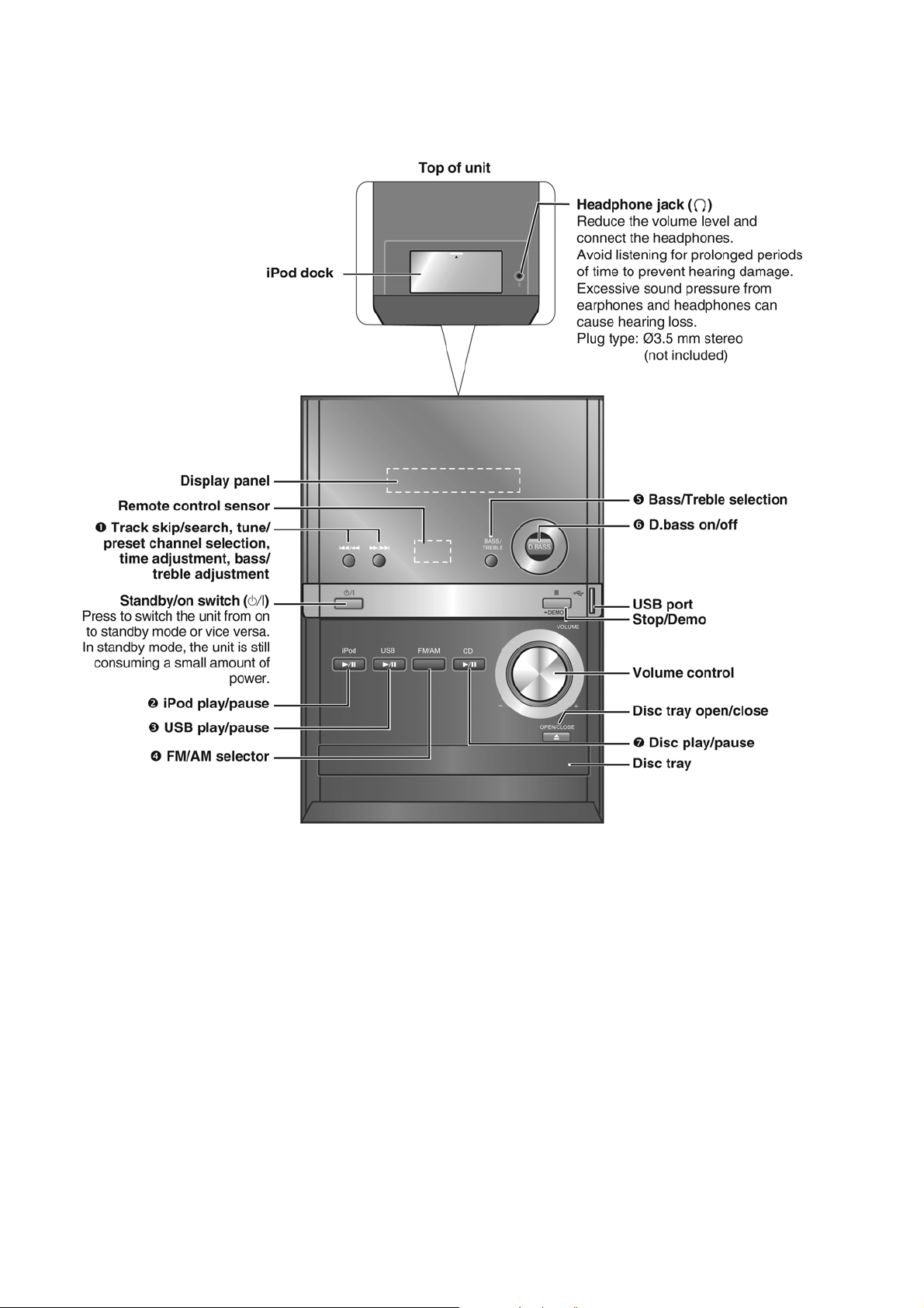
5 Location of Controls and Components
5.1. Main Unit Key Button Operations
12

5.2. Remote Control Key Button Operations
13
5.3. Media Information
This unit can play MP3 les and CD-DA format audio CD-R/RW that
have been nalized.
This unit can access up to 99 tracks.
It may not be able to play some CD-R/RW depending on the
condition of the recording.
Do not use irregularly shaped discs.
Do not use discs with labels and stickers that are coming o or with
adhesive exuding from under labels and stickers.
Do not attach extra labels or stickers on the disc.
Do not write anything on the disc.
t
t
t
t
t
t
Using DualDisc
The “CD” sides of DualDisc do not meet the CD-DA standard so it
may not be possible to play them on this unit.
Files are treated as tracks and folders are treated as albums.
This unit can access up to 999 tracks, 255 albums and 20 sessions.
Files must have the extension: “.MP3” or “.mp3”
Disc must conform to ISO9660 level 1 or 2 (except for extended
formats).
To play in a certain order, prex the folder and le names with the
3-digit numbers in the order you want to play them.
t
t
t
t
CD
MP3
Note
Charging the iPod
iPod will start recharging regardless of whether this
unit is in On or Standby condition.
“IPOD ¼” will be shown on the main unit’s display
during iPod charging in main unit standby mode.
Check iPod to see if the battery is fully recharged.
If you are not using iPod for an extended period of
time after recharging has completed, disconnect
it from main unit, as the battery will be depleted
naturally. (Once fully recharged, additional recharging
will not occur.)
iPod will not charge when the main unit is in USB
mode.
t
t
t
t
t
Compatible iPod
Name Memory size
iPod touch 2nd generation 8 GB, 16 GB,
32 GB
iPod nano 4th generation (video) 8 GB, 16 GB
iPod classic 120 GB
iPod touch 1st generation 8 GB, 16 GB,
32 GB
iPod nano 3rd generation (video) 4 GB, 8 GB
iPod classic 80 GB, 160 GB
iPod nano 2nd generation
(aluminum)
2 GB, 4 GB,
8 GB
iPod 5th generation (video) 60 GB, 80 GB
iPod 5th generation (video) 30 GB
iPod nano 1st generation 1 GB, 2 GB,
4 GB
iPod 4th generation (colour display) 40 GB, 60 GB
iPod 4th generation (colour display) 20 GB, 30 GB
iPod 4th generation 40 GB
iPod 4th generation 20 GB
iPod mini 4 GB, 6 GB
Compatibility depends on the software version of your
iPod.
t
iPod is a trademark of Apple Inc., registered in the U.S.
and other countries.
Devices which are dened as USB mass storage
class:
USB devices that support bulk only transfer.
USB devices that support USB 2.0 full speed.
t
t
Files must have the extension “.mp3” or “.MP3”.
CBI (Control/Bulk/Interrupt) is not supported.
A device using NTFS le system is not supported
[Only FAT12/16/32 (File Allocation Table 12/16/32) le
system is supported].
Depending on the sector size, some les may not
work.
This unit can access up to 255 albums (including blank
folders) and 2500 tracks.
The maximum number of tracks in a folder are 999
tracks.
Only one memory card will be selected when
connecting a multiport USB card reader. Typically the
rst memory card inserted.
Do not unplug the USB device during reading or
playback.
Disconnect the USB card reader from the unit when
you remove the memory card. Failure to do so may
cause malfunction to the device.
When you connect a compatible digital audio player
to the USB port, charging may be activated. It will not
charge when the unit is switched to standby mode or
iPod mode.
t
t
t
t
t
t
t
t
t
USB compatible devices
USB supported format
Note
14

6 Self-diagnostic and special mode setting
This unit is equipped with features of self-diagnostic & special mode setting for checking the functions & reliability.
6.1. Entering into Self-diagnostic Mode
Here is the procedure to enter into self-diagnostic mode:
Step 1 : Switch to CD function
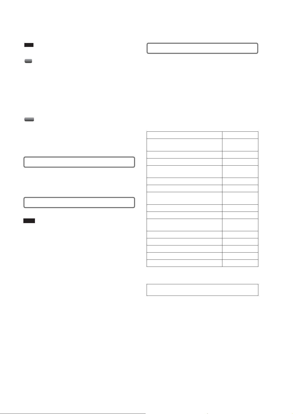
Step 2 : Press the [ ] key of the main set for more than 2 seconds. While pressing this key, press the [ ] key on the main
set for another 2 seconds to enter into the Self-diagnostic mode. The FL shall display :-
To exit the Self-diagnostic mode
Press button on main unit or remote control.
6.2. Self-diagnostic Function Error Code
Self-diagnostic Function provides information on any problems o ccuring for the unit and its respective components by displaying
error codes. Thesed error code such as U**, H** and F** are stored in memory and held unless it is cleared.
The error code is automatically display after entering into self-diagnostic mode.
6.2.1. CD Mechanism Error Code Table
Error Code Diagnosis Contents Description of error Automatic FL Display Remarks
H15 CD Open SW Abnormal During normal operation
CD OPEN SW On fail to be
detected with 4 sec. Error
No. shall be clear by force
or during cold start.
F15 CD REST SW Abnormal CD traverse position intial
setting operation failsafe
counter (1000 ms) waiting
for REST SW to turn on.
Error No. shall be clear by
force or during cold start.
F26 Communication between
CD servo LSI and micro-p
abnormal.
CD function DTMS command, after system setting, If SENSE = 'L' cannot
be detected. Memory shall
contain F26 code. After
Power on, CD function
shall continue, error displ a y s h a ll b e " N O D I S C" .
Error No. shall be clear by
force or cold start.
Press [ ] on main
unit for next error.
Press [ ] on main
unit for next error.
Press [ ] on main
unit for next error.
6.2.2. Power Supply Error Code Table
Error Code Diagnosis Contents Description of error Automatic FL Display Remarks
F76 Power Amp IC output
abnormal
DCDET1 = L (NG)
Press [ ] on main
unit for next error.
15
6.3. Entering into Doctor Mode
Here is the procedure to enter into doctor mode :
Press [ ] button on main unit follow by [4] and [7] on remote control. The FL shall display :-
To exit the Doctor mode
Press bu tton on main unit or remote control.
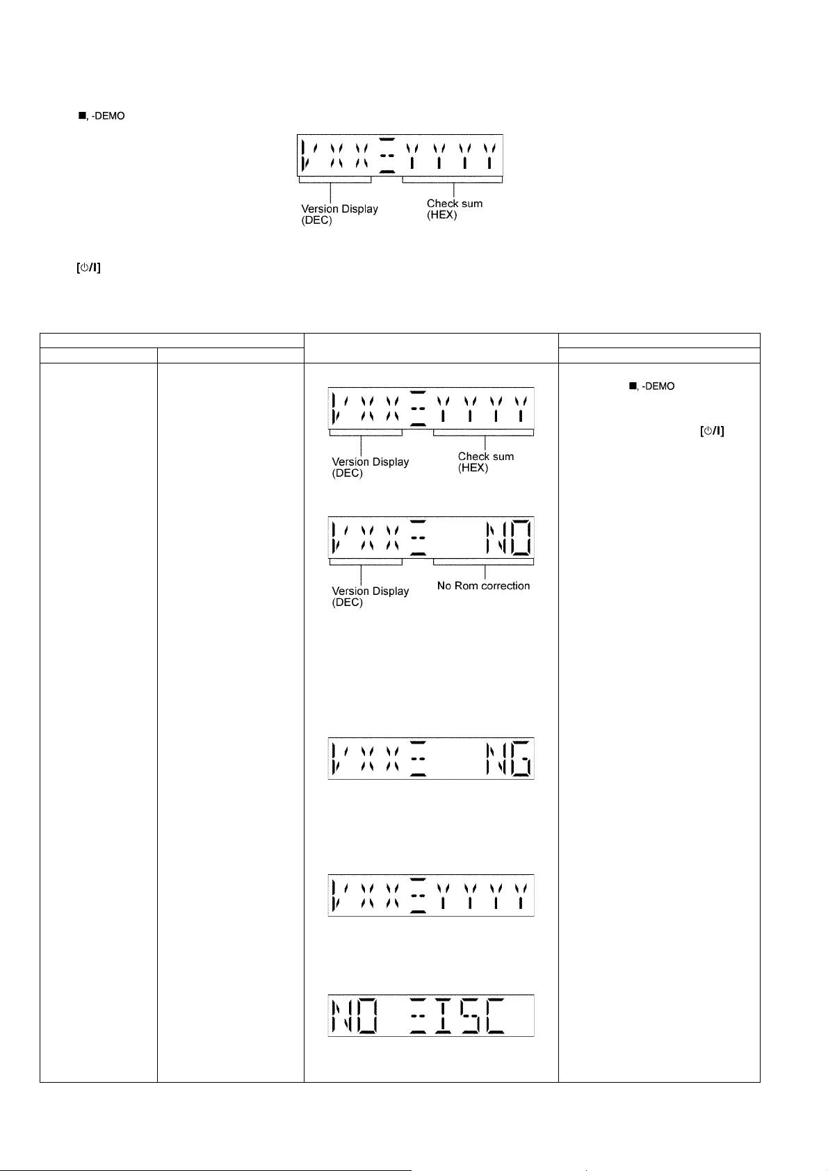
6.3.1. Doctor Mode Table 1
Item FL Display Key Operation
Mode Name Description Front Key
Doctor Mode To enter into Doctor Mode
for checking of various
items and displaying
EEPROM and firmware version.
Note: The micro-processor
version as shown is an
example. It will be revise
when there is an updates.
FL Display sequence Display 1 → 2
(Display 1)
Checksum : (Condition 1)
In CD mode:
1. Press [ ] button on main
unit follow by [4] and [7] on
remote control.
To exit Doctor Mode, press button on main unit or remote control.
(a) If there is NO EEPROM header string
OR
(b) If there is no EEPROM ( no data is
received by micro-processor) [NO] is displayed.
Checksum : (Condition 2)
If the version of the EEPROM does not
match or not working properly [NG] is display.
Checksum : (Condition 3)
If the EEPROM version matches, checksum
[YYYY] is displayed.
(Display 2)
The Checksum of EEPROM and firmware
version will be display for 2 sec.
16

6.3.2. Doctor Mode Table 2
Item FL Display Key Operation
Mode Name Description Front Key
FL Display Test To check the FL segments
display (All segments will
light up)
Volume Setting
check
CD Loading Test
(DLS6C)
To check for volume setting
during this mode, Bass &
treble is set to 0dB & EQ is
switch off.
T o determine the reliability of
CD Loading unit.
To check for the Open/Close
operation for the CD loading
unit. It fails when there is
abnormality in opening or
closing.
In Doctor Mode:
1. Press [DIMMER] button on
remote control.
To cancel, press [0] button on remote
control.
To exit Doctor Mode, press button on main unit or remote control.
In Doctor Mode:
1. Press [7] button on remote control.
To exit Doctor Mode, press but-
ton on main unit or remote control.
In Doctor Mode:
2. Press [8] button on remote control.
To exit Doctor Mode, press but-
ton on main unit or remote control.
In Doctor Mode:
3. Press [9] button on remote control.
To exit Doctor Mode, press but-
ton on main unit or remote control.
In Doctor Mode:
1. Press [ ], [1], [1] button on
remote control.
To cancel, press [0] button on remote
control.
To exit Doctor Mode, press button on main unit or remote control.
CD Traverse Test
(DLS6C)
CD Combination Test
(DLS6C)
Cold Start To activate cold start upon
T o check for the traverse unit
operation. In this mode, the
first & last track is access &
read. (TOC). It fails when
TOC is not completed by IOS
or the traverse is out of
focus.
A combination of CD loading
& traverse unit test.
next AC power up. It will set
to factory shipment condition.
(Refer to section 6.4.3 for more information)
In Doctor Mode:
1. Press [ ], [1], [2] button on
remote control.
To cancel, press [0] button on remote
control.
To exit Doctor Mode, press button on main unit or remote control.
(Refer to section 6.4.4 for more information)
In Doctor Mode:
1. Press [ ], [1], [3] button on
remote control.
To cancel, press [0] button on remote
control.
To exit Doctor Mode, press button on main unit or remote control.
(Refer to section 6.4.5 for more information)
In Doctor Mode:
1. Press [SLEEP] button on remote
control.
To exit Doctor Mode, press button on main unit or remote control.
17

Item FL Display Key Operation
OPEN
Operation
OPEN wait
for 1 s
CLOSE
Operation
CLOSE
wait for 4s
Count Up
First Track
Access
Last Track
Access
First Track
Play 5 s
Last Track
Play 5 s
Count Up
Mode Name Description Front Key
USB Test Mode To check for USB operation.
The display will appear after 3s,
In Doctor Mode:
1. Select to USB mode.
2. Press [2] button on remote control.
To exit Doctor Mode, press button
on main unit or remote control.
6.3.3. DLS6 Loading Test
6.3.4. DLS6 Traverse Test
18
6.3.5. DLS6 Combination Test
First Track
Access
Last Track
Access
First Track
Play 10 s
Last Track
Play 10 s
OPEN
Operation
OPEN wait
for 1 s
CLOSE
Operation
Count Up
19
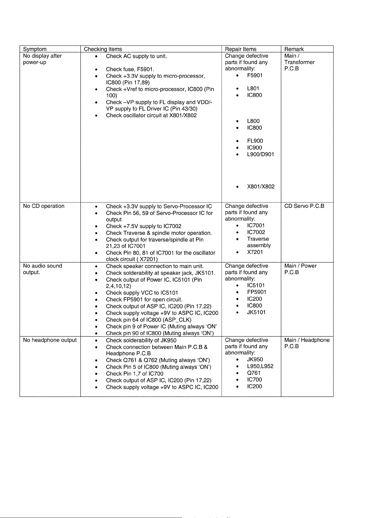
7 Troubleshooting Guide
20

8 Service Fixture & Tools
Prepare service tools before proccess service position.
Service Tools Remarks
Main P.C.B. (CN901) - Panel P.C.B. (CN900) REEX1022 (11P FFC)
21

9 Disassembly and Assembly Instructions
Caution Note:
• This section describes the disassembly and/or assembly procedures for all major printed circuit boards & main components for the unit. (You may refer to the section of “Main compo nents and P.C.B Locations” as described in the service
manual)
• Before carrying out the disassembly process, please ensure all the safety precautions & procedures are followed.
• During the disassembly and/or assembl y process, please handle with car e as there may be chassis components with
sharp edges.
• Avoid touching heatsinks due to its high temperature after prolong use. (See caution as described below)
• During disassembly and assembly, please ensure proper service tools, equipments or jigs is being used.
• During replacement of component parts, please refer to the section of “Replacement Parts List” as described in the
service manual.
• Select items from the following indexes when disassembly or replacement are required.
• Disassembly of Top Cabinet Assembly
• Disassembly of Headphone P.C.B.
• Disassembly of iPod P.C.B.
• Disassembly of iPod Lid
• Disassembly of Front Panel Assembly
• Disassembly of USB P.C.B.
• Disassembly of Panel P.C.B.
• Disassembly of FL Window
• Disassembly of Centre Ornament
• Disassembly of CD Lid
• Disassembly of CD Mechanism Unit (DLS6C)
• Disassembly of Power P.C.B.
• Replacement of Power Amp IC (IC5101)
• Disassembly of Main P.C.B.
• Disassembly of Fan Unit
• Disassembly of Transformer P.C.B.
• Replacement of Transistor (Q5901)
• Disassembly of CD Servo P.C.B.
22

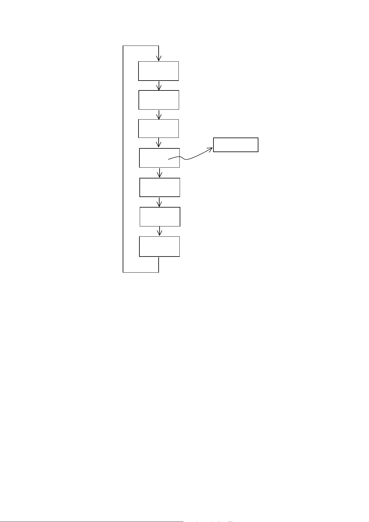
9.1. Disassembly flow chart
The following chart is the procedure for disassembling the casing and inside parts for internal inspection when carrying out the servicing.
To assemble the unit, reverse the steps shown in the chart below.
23
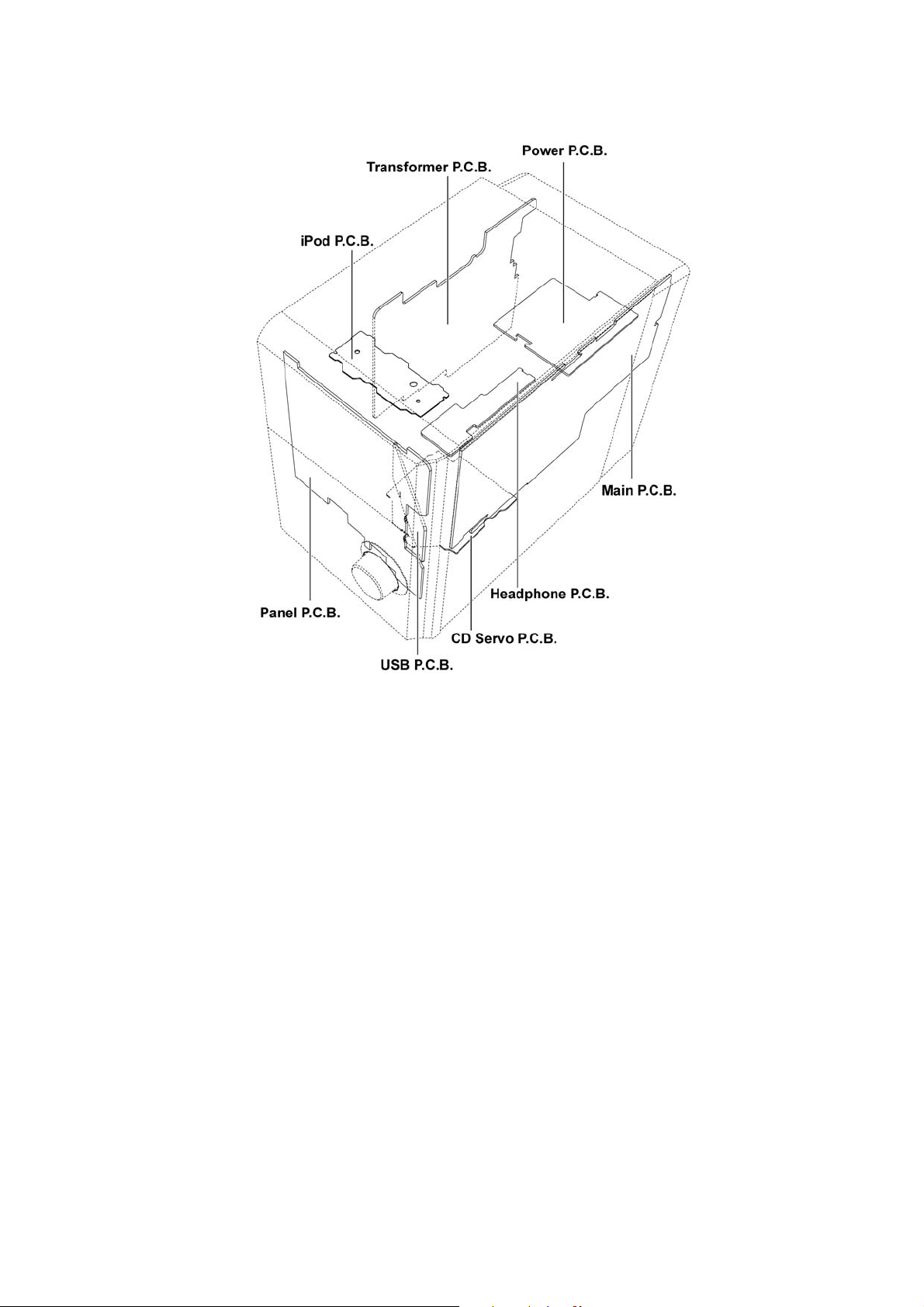
9.2. Main Parts Location Diagram
24

9.3. Disassembly of Top Cabinet Assembly
Step 1 : Remove 3 screws.
Step 2 : Remove 3 screws.
Step 3 : Remove 3 screws.
Step 4 : Lift up the Top Cabinet Assembly and remove it.
Caution : During assembling, ensure the Top Cabinet
Assembly is seated properly.
25

Step 5 : Upset the Top Cabinet Assembly as arrow shown.
Step 6 : Place a support block underneath the Top Cabinet
Assembly.
9.4. Disassembly of Headphone P.C.B.
• Refer to “Disassembly of Top Cabinet Assembly”.
Step 1 : Remove 2 screws.
Step 2 : Release guide and remove Headphone P.C.B..
Step 7 : Detach 5P cable at connector (CN902) on Main P.C.B..
Step 8 : Detach 14P FFC at connector (CN350) on Main
P.C.B..
Step 9 : Remove Top Cabinet Assembly.
26

9.5. Disassembly of iPod P.C.B.
• Refer to “Disassembly of Top Cabinet Assembly”.
9.6. Disassembly of iPod Lid
• Refer to “Disassembly of iPod P.C.B.”
Step 1 : Remove 2 screws.
Step 2 : Remove iPod P.C.B..
Caution : During assembling, ensure the iPod P.C.B. is
seated properly.
Step 1 : Remove 1 screw.
27

Step 2 : Using minus screwdriver slightly to release the iPod
cover lid from the catch.
Caution : Do not exert strong force to the iPod cov er lid
during removal.
Step 3 : Slightly lift up the iPod cover lid as arrow shown.
Step 4 : Remove the iPod cover lid as arrow shown.
28
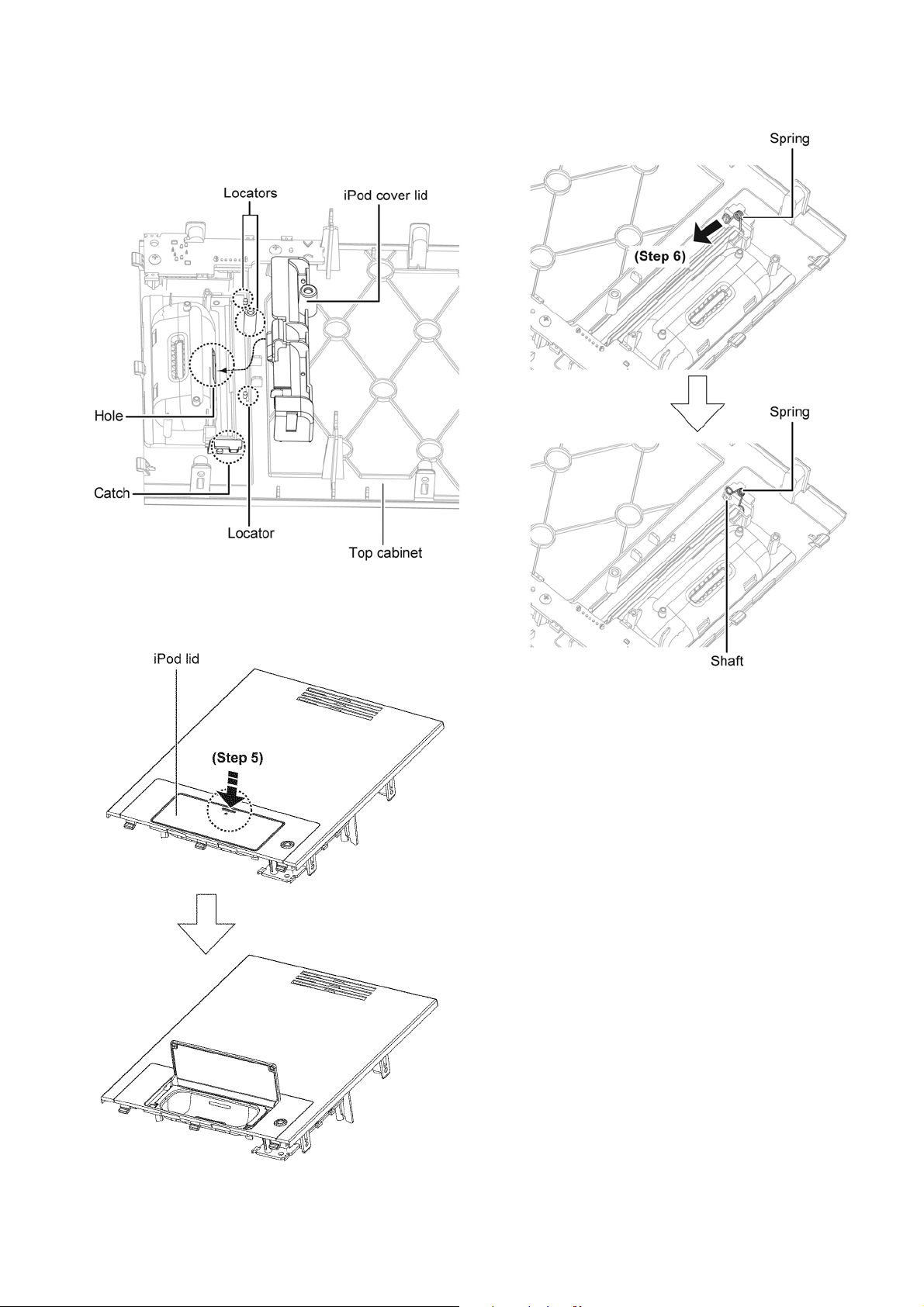
Caution 1 : During assembling, ensure the iPod cover lid is
properly seated on the locators and slot i nto the hole of
the top cabinet.
Caution 2 : During assembling, ensure the iPod cover lid is
properly catch to the top cabinet and a “click” sound will
be heard when fully catched.
Step 6 : Release the spring from the shaft of the top cabinet.
Step 5 : Open the iPod lid by pressing as arrow shown.
29

Step 7 : Release the spring from the shaft of the iPod lid. Step 8 : Remove the spring as arrow shown.
Caution : Keep the spring in a safe place and place it back
during assembling.
Step 9 : Using minus screwdriver to release the shaft (A) of the
iPod lid.
Caution : Do not exert strong force to the iPod lid during
removal.
30
 Loading...