

Panasonic SAPM-41-P Service manual
A
CD Stereo System
SA-PM41P
SA-PM41PC
Colour
(S)... Silver Type
ORDER NO. MD0501004C1
A6
Specification
n Amplifier Section
Power output
10%, Total harmonic distortion
60 Hz-3 kHz, both channels driven
(Low channel) 26 W per channel (6 Ω)
3 kHz-16 kHz, both channels driven
(High channel) 29 W per channel (6 Ω)
Total Bi-Amp power 55 W per channel
Power output
10% Total harmonic distortion
1 kHz, both channels driven
(Low channel) 35 W per channel (6 Ω)
8 kHz, both channels driven
(High channel) 35 W per channel (6 Ω)
Total Bi-Amp power 70 W per channel
Output Impedance
Headphone 16Ω -32Ω
n FM Tuner Section
Frequency range 87.5 MHz - 108.0 MHz
(100 kHz steps)
87.9 MHz - 107.9 MHz
(200 kHz steps)
Sensitivity 1.5 µV (IHF)
S/N 26dB 1.5 µV
ntenna terminal(s) 75 Ω (unbalanced)
n AM Tuner Section
Frequency range 520kHz - 1710 kHz (10kHz steps)
Sensitivity
S/N 20 dB (at 1000 kHz) 560 µV/m
n Cassette Deck Section
Track system 4 track, 2 channel
Heads
Record/playback Solid permalloy head
Erasure Double gap ferrite head
Motor DC servo motor
Recording system AC bias 100 kHz
Erasing system AC erase 100 kHz
Tape speed 4.8 cm/s
Overall frequency response (+3 dB, -6 dB) at DECK OUT)
NORMAL (TYPE I) 35 Hz - 14 kHz
S/N RATIO 45dB (A weighted)
Wow and flutter 0.10% (WRMS)
Fast forward and rewind time Approx. 120 seconds with C-60
cassette tape
n CD Section
Disc
CD, CD-R, CD-RW, MP3 8cm / 12cm (33/20”/473/
Sampling frequency 44.1 kHz
Decoding 16 bit linear
Beam source / wavelength Semiconductor laser / 780 nm
Number of channels Stereo
Frequency response 20 Hz - 20 kHz (+1dB, -2 dB)
Wow and flutter Below measurable limit
Digital filter 8fs
100
”)
© 2005 Matsushita Electric Industrial Co. Ltd.. All
rights reserved. Unauthorized copying and
distribution is a violation of law.
SA-PM41 P / SA-PM41 PC
D/A converter MASH (1 bit DAC)
MP3
Bit rate 32kbps - 320kbps
Sampling frequency 32kHz, 44.1kHz, 48kHz
n Speaker Section
Type 2 way, 2 speaker system
Speaker(s)
Full Range 10 cm (4”) cone type
Tweeter 6cm(23/8”) cone type
Impedance 6 Ω
Input power
HIGH 70 W (Max)
LOW 70 W (Max)
Output sound pressure level 80 dB/W (1.0 m)
Frequency range 55 Hz - 22 kHz (-16 dB)
70 Hz - 20 kHz (-10 dB)
Dimensions (W x H x D) 128 mm x 250 mm x 222 mm
1
(5
/32”x927/32”x83/4”)
Mass 1.95 kg (4.30 Ibs)
n General
Power supply AC120V,60Hz
Power consumption 130 W
Dimensions (W x H x D) 179 mm x 250 mm x 383 mm
Mass 5.24 kg (11.55 Ibs)
Power consumption in standby
mode
Notes :
1. Specifications are subject to change without notices. Mass and
dimensions are approximate.
2. Total harmonic distortion is measured by the digital spectrum
analyzer.
3. The labels “HIGH” and “Low” on the rear of the speakers.
n System : SC-PM41P- S
n System : SC-PM41PC-S Music center: SA-PM41PC-S
1
(7
/16”x927/32”x153/12”)
0.8 W
Music center: SA-PM41P-S
Speaker: SB-PM41P-S
Speaker: SB-PM41P-S
CONTENTS
Page Page
1 Safety Precautions
1.1. GENERAL GUIDELINES
2 Before Repair and Adjustment
3 Protection Circuitry
4 Handling the Lead-free Solder
4.1. About lead free solder (PbF)
5 Precaution of Laser Diode
6 Handling Precautions For Traverse Deck
7 Accessories
8 Operation Procedures
9 Information on Disc & MP3
10 Assembling and Disassembling
10.1. Disassembly flow chart
10.2. Disassembly of Side Panel L & R
10.3. Disassembly of Top Cabinet
10.4. Disassembly of Deck P.C.B. and Tape Eject P.C.B.
10.5. Disassembly of Front Panel
10.6. Disassembly of Main Control P.C.B., Function P.C.B. and
Power In P.C.B.
10.7. Disassembly of Panel P.C.B.
10.8. Disassembly of Rear Cabinet
10.9. Disassembly of Main P.C.B.
10.10. Disassembly of Transformer P.C.B.
10.11. Disassembly of Tuner Pack
10.12. Disassembly of Power P.C.B.
10.13. Disassembly of CR16 Mechanism
10.14. Replacement of C D Lid
4
4
6
6
7
7
8
9
10
11
12
13
13
14
14
14
15
16
17
17
18
18
19
19
19
20
10.15. Replacement of Cassette Lid
10.16. Replacement of the Power IC and Transistors
10.17. Procedure fo r Replacing Pinch Roller and Head Block
(Cassette Mechanism Unit)
10.18. Procedure fo r Replacing Motor, Capstan Belt A, Capstan
Belt B, and Winding Belt (Cassette Mechanism Unit)
10.19. Procedure fo r Replacing Parts on Mechanism PCB
10.20. Disassembly of CR16 Mechanism
10.21. Replacement of optical pickup unit (CD mechanism)
10.22. Replacement of a traverse gear A and a traverse gear B
10.23. Procedure fo r removing CD loading mechanism
10.24. CR16 mechanism disassembly procedure
10.25. CR16 MECHANISM ASSEMBLY PROCEDURE
10.26. Disassembly of traverse mechanism
10.27. Handling of cassette tape jam
11 Service Positions
11.1. Checking procedure
11.2. Checking the major P.C.B
12 Self-Diagnostic Display Function
12.1. Entering into Self-Diagnostic Mode
12.2. Clearing Self-Diagnostic Memory
12.3. Displaying Self-Diagnostic Results
12.4. Error Code Table
12.5. Cassette Mechanism Self-Diagnostic Mode
12.6. Changer Reliability Test Mode
12.7. Changer Operation Checking
21
22
23
23
25
25
26
28
29
29
35
48
49
50
50
50
51
51
52
53
53
54
54
55
2

12.8. CR16 Mechanism Ageing Mode 55
13 Procedure for Checking Operation of Individual Parts of
Cassette Mechanism Unit
13.1. Operation Check with Cassette Tape
13.2. Operation Check without Cassette Tape
14 Measurement And Adjustments
14.1. Cassette Deck Section
15 Voltage Measurement
15.1. CD Servo P.C.B. (REPV0039A)
15.2. Main P.C.B. (REPV0062A)
15.3. Main Control P.C.B. (REPV0062A)
15.4. Deck P.C.B. (REPV0016B)
15.5. Deck Mechanism P.C.B. (REPX0321H)
15.6. CD Loading P.C.B. (REP3569A)
15.7. Power P.C.B. (REPV0038F)
15.8. Panel P.C.B. (
REPV0062A)
15.9. Transformer P.C.B. (REPV0038F)
16 Waveform Chart
17 Block Diagram
17.1. CD SERVO Block
17.2. MAIN Block
18 Notes of Schematic Diagram
19 Schematic Diagram
19.1. CD SERVO CIRCUIT
19.2. MAIN CIRCUIT
19.3. MAIN CONTROL CIRCUIT, PANEL CIRCUIT, POWER IN
CIRCUIT and FUNCTION CIRCUIT
19.4. DECK CIRCUIT, DECK MECHANISM CIRCUIT and TAPE
EJECT CIRCUIT
19.5. POWER CIRCUIT
19.6. TRANSFORMER CIRCUIT
57
57
57
59
59
61
61
62
63
63
63
64
64
19.7. CD LOADING CIRCUIT
20 Printed Circuit Board
20.1. CD SERVO P.C.B.
20.2. MAIN P.C.B.
20.3. MAIN CONTROL P.C.B. and PANEL P.C.B.
20.4. POWER IN P.C.B., FUNCTION P.C.B. and DECK
MECHANISM P.C.B.
20.5. DECK P.C.B. and TAPE EJECT P.C.B.
20.6. POWER P.C.B.
20.7. TRANSFORMER P.C.B.
20.8. CD LOADING P.C.B.
21 Wiring Connection Diagram
22 Illustration of IC 痴, Transistors and Diodes
23 Terminal Function of ICエs
64
64
65
66
66
68
74
75
75
77
23.1. IC302 (C2CBJG000575) MICRO PROCESSOR
23.2. IC702 (MN6627953HB) Servo processor/ Digital signal
processor/ Digital filter/ D/A converter
23.3. IC703 (BA5948FPE2) IC 4CH DRIVE
24 Troubleshooting Flowchart (CD Section Circuit)
25 Parts Location and Replacement Parts List
25.1. Deck Mechanism
25.2. CD LOading Mechanisms
25.3. Cabinet Part List
25.4. Electrical Part List
25.5. Packaging Materials & Accessories Parts List
81
25.6. Packaging
84
SA-PM41 P / SA-PM41 PC
86
89
90
91
91
92
94
95
96
97
98
99
100
102
103
103
104
104
106
108
109
111
116
120
129
129
3
SA-PM41 P / SA-PM41 PC
1 Safety Precautions
1.1. GENERAL GUIDELINES
1. When servicing, observe the original lead dress. If a short circuit is found, replace all parts which have been overheated or
damaged by the short circuit.
2. After servicing, ensure that all the protective devices such as insulation barriers, insulation papers shields are properly installed.
3. After servicing, check for leakage current checks to prevent from being exposed to shock hazards.
(This “Safety Precaution” is applied only in U.S.A.)
1. Before servicing, unplug the power cord to prevent an electric shock.
2. When replacing parts, use only manufacture r’s recommende d components for safety.
3. Check the condition of the power cord. Replace if wear or damage is evident.
4. After servicing, be sure to restore the lead dress, insulation barriers, insulation papers, shields, etc.
5. Before returning the serviced equipment to the customer, be sure to make the following insulation resistance test to prevent the
customer from being exposed to a shock hazard.
1.1.1. LEAKAGE CURRENT COLD CHECK
1. Unplug the AC cord and connect a jumper between the two prongs on the plug.
2. Using an ohmmeter measure the resistance value, between the jumpered AC plug and each exposed metallic cabinet part on
the equipment such as screwheads, connectors, control shafts, etc. When the exposed metallic part has a return path to the
chassis, the reading should be between 1MΩ and 5.2Ω.
When the exposed metal does not have a return path to the chassis, the reading must be
.
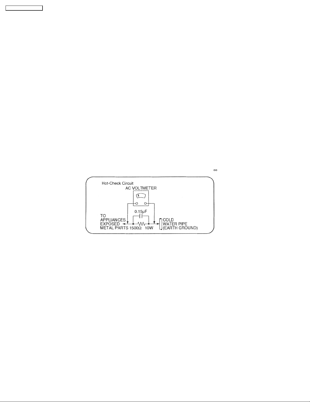
Fig. 1
1.1.2. LEAKAGE CURRENT HOT CHECK (See Figure 1.)
1. Plug the AC cord directly into the AC outlet. Do not use an isolation transformer for this check.
2. Connect a 1.5kΩ , 10 watts resistor, in parallel with a 0.15µF capacitors, between each exposed metallic part on the set and a
good earth ground such as a water pipe, as shown in Figure 1.
3. Use an AC voltmeter, with 1000 ohms/volt or more sensitivity, to measure the potential across the resistor.
4. Check each exposed metallic part, and measure the voltage at each point.
5. Reverse the AC plug in the AC outlet and repeat each of the above measuremen ts.
6. The potential at any point should not exceed 0.75 volts RMS. A leakage current tester (Simpson Model 229 or equivalent) may
be used to make the hot checks, leakage current must not exceed 1/2 milliamp. should the measuremen t is outside of the limits
specified, there is a possibility of a shock hazard, and the equipment should be repaired and re-checked before it is returned
to the customer.
4

1.1.3. Caution for fuse replacement
SA-PM41 P / SA-PM41 PC
5

SA-PM41 P / SA-PM41 PC
2 Before Repair and Adjustment
Disconnect AC power, discharge Power Supply Capacitors C506, C507, C508, C601, C602, C600, & C620 through a 10Ω,1W
resistor to ground.
DO NOT SHORT-CIRCUIT DIRECTLY (with a screwdriver blade, for instance), as this may destroy solid state devices.
After repairs are completed, restore power gradually using a variac, to avoid overcurrent.
· Current consumption at AC 120V, 60 Hz in NO SIGNAL mode should be ~300 mA.
3 Protection Circuitry
The protection circuitry may have operated if either of the following conditions are noticed:
· No sound is heard when the power is turned on.
· Sound stops during a performance .
The function of this circuitry is to prevent circuitry damage if, for example, the positive and negative speaker connection wires are
"shorted", or if speaker systems with an impedance less than the indicated rated impedance of the amplifier are used.
If this occurs, follow the procedure outlines below:
1. Turn off the power.
2. Determine the cause of the problem and correct it.
3. Turn on the power once again after one minute.
Note:
When the protection circuitry functions, the unit will not operate unless the power is first turned off and then on again.
6

SA-PM41 P / SA-PM41 PC
4 Handling the Lead-free Solder
4.1. About lead free solder (PbF)
Distinction of PbF P.C.B.:
P.C.B.s (manufacture d) using lead free solder will have a PbF stamp on the P.C.B.
Caution:
· Pb free solder has a higher melting point than standard solder; Typically the melting point is 50 - 70°F (30 - 40°C) higher. Please
use a high temperature soldering iron. In case of soldering iron with temperature control, please set it to 700 ± 20°F (370 ±
10°C).
· Pb free solder will tend to splash when heated too high (about 1100°F/600°C).
· W hen soldering or unsoldering, please completely remove all of the solder on the pins or solder area, and be sure to heat the
soldering points with the Pb free solder until it melts enough.
7
SA-PM41 P / SA-PM41 PC
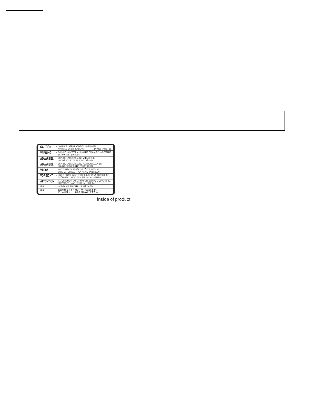
5 Precaution of Laser Diode
CAUTION:
This unit utilizes a class 1 laser.
Invisible laser radiation is emitted from the optical pickup lens.
When the unit is turned on:
1. Do not look directly into the pick up lens.
2. Do not use optical instruments to look at the pick up lens.
3. Do not adjust the preset variable resistor on the pickup lens.
4. Do not disassemble the optical pick up unit.
5. If the optical pick up is replaced, use the manufacture r’s specified replacement pick up only.
6. Use of control or adjustments or performance of procedures other than those specified herein may result in hazardous radiation
exposure.
CAUTION!
THIS PRODUCT UTILIZES A LASER.
USE OF CONTROLS OR ADJUSTMENTS OR PERFORMANCE OF PROCEDURES OTHER THAN THOSE SPECIFIED HEREIN MAY RESULT
IN HAZARDOUS RADIATION EXPOSURE.
8
SA-PM41 P / SA-PM41 PC
6 Handling Precautions For Traverse Deck
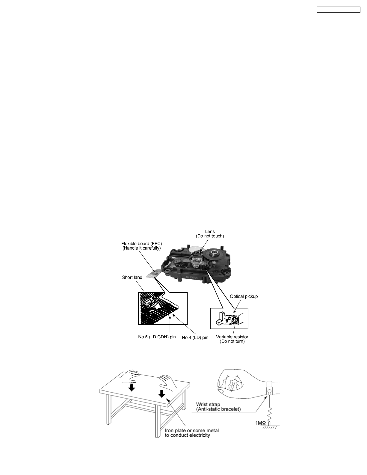
The laser diode in the traverse deck (optical pickup) may break down due to potential difference caused by static electricity of
clothes or human body. So, be careful of electrostatic breakdown during repair of the traverse deck (optical pickup).
· Handling of traverse deck (optical pickup)
1. Do not subject the traverse deck (optical pickup) to static electricity as it is extremely sensitive to electrical shock.
2. To prevent the breakdown of the laser diode, an antistatic shorting pin is inserted into the flexible board (FFC board).
3. Take care not to apply excessive stress to the flexible board (FFC board). When removing or connecting the short pin, finish
the job in as short time as possible. (Fig 6.1)
4. Do not turn the variable resistor (laser power adjustment). It has already been adjusted.
· Grounding for electrostatic breakdown prevention
1. Work table grounding. (Fig 6.2)
Use the anti-static wrist strap to discharge the static electricity from your body.
2. Work table grounding. (Fig 6.2)
Put a conductive material (sheet) or steel sheet on the area where the traverse deck (optical pickup) is place, and ground
the sheet.
Caution:
The static electricity of your clothes will not be grounded through the wrist strap. So, take care not to let your clothes touch the
traverse deck (optical pickup).
Caution when replacing the Traverse Deck
The traverse deck has a short point shorted with solder to protect the laser diode against electrostatics breakdown. Be sure to
remove the solder from the short point before making connections.
(Fig 6.1)
(Figs 6.2)
9
SA-PM41 P / SA-PM41 PC
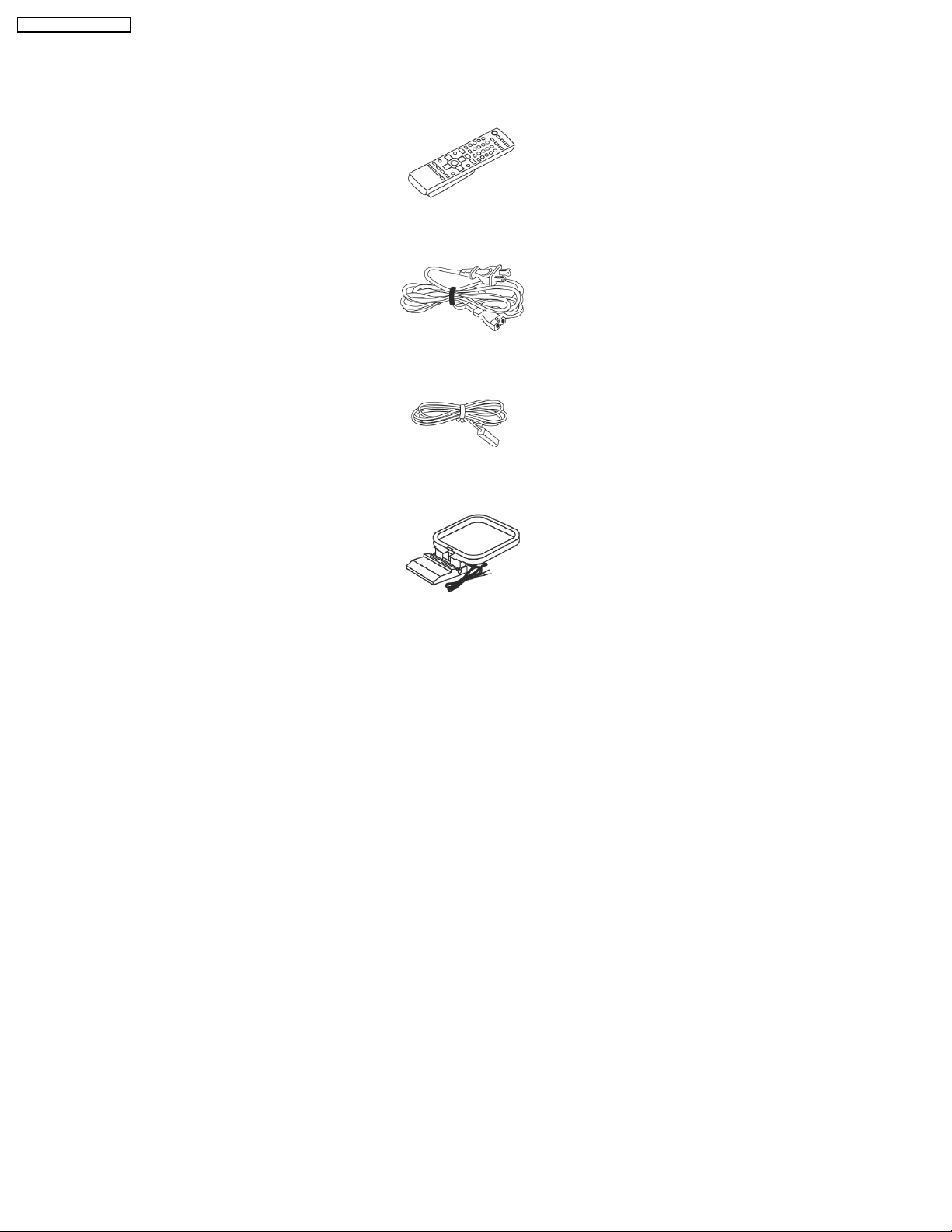
7 Accessories
Note : Refer to Packing Materials & Accessories Parts List (Section 25.5) for the part number.
Remote Control
AC power cord
FM indoor antenna
AM loop antenna
10
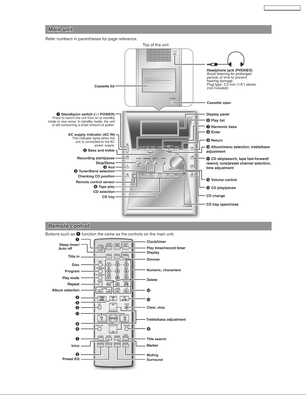
8 Operation Procedures
SA-PM41 P / SA-PM41 PC
11
SA-PM41 P / SA-PM41 PC
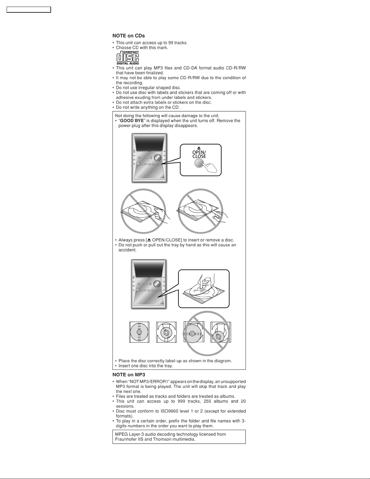
9 Information on Disc & MP3
12
SA-PM41 P / SA-PM41 PC
10 Assembling and Disassembling
“ATTENTION SERVICER”
Some chassis components may be have sharp edges. Be careful when disassemblin g and servicing.
1. This section describes procedures for checking the operation of the major printed circuit boards and replacing the main
components.
2. For reassembly after operation checks or replacement, reverse the respective procedures.
Special reassembly procedures are described only when required.
3. Select items from the following index when checks or replacement are required.
Warning:
This product uses a laser diode. Refer to “Precaution of Laser Diode”.
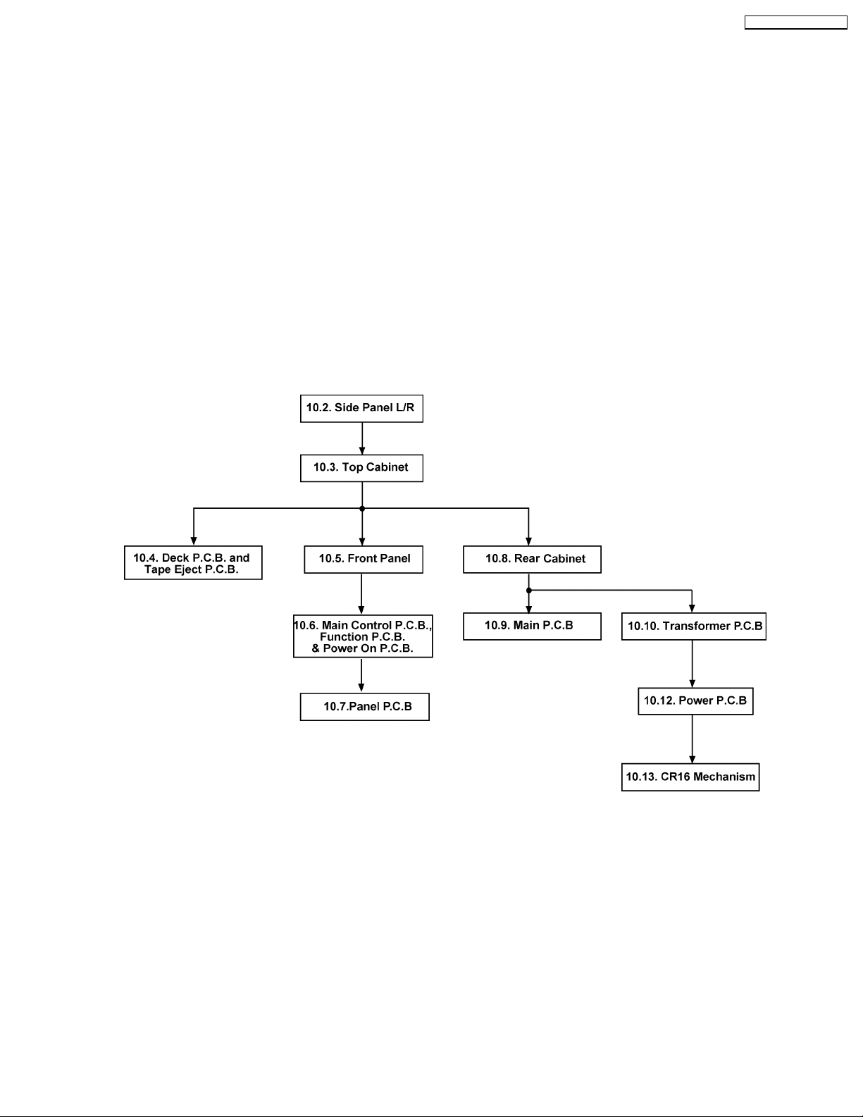
10.1. Disassembly flow chart
The following chart is the procedure for disassemblin g the casing and inside parts for internal inspection when carrying out the
servicing.
To assemble the unit, reverse the steps shown in the chart below.
13
SA-PM41 P / SA-PM41 PC
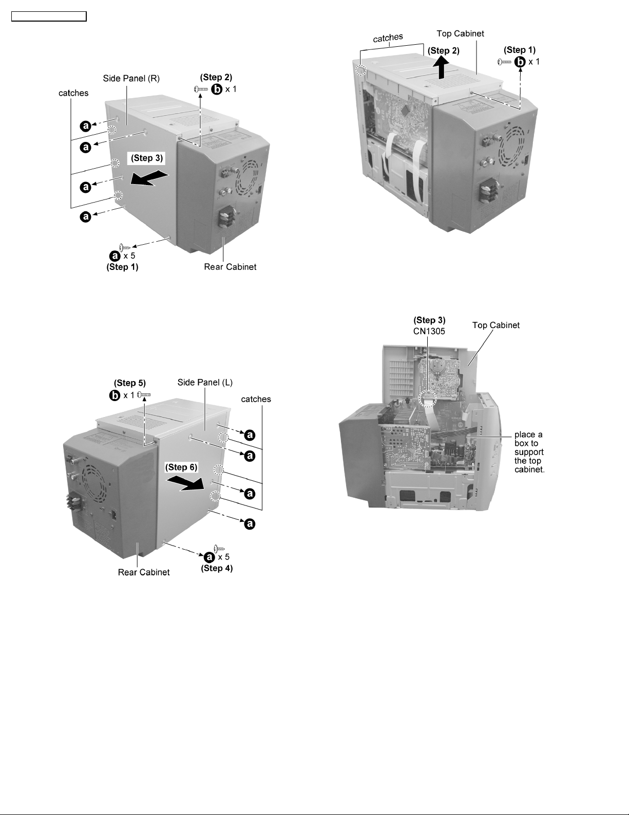
10.2. Disassembly of Side Panel L &
R
Step 1 : Remove 5 screws from the side panel (R).
Step 2 : Remove 1 screws from the corner of the side panel
(R).
Step 3 : Remove the side panel as arrow shown (Be careful of
the catches).
Step 1 : Remove 1 screws.
Step 2 : Lift up the top cabinet as arrow shown (Be careful of
the catches).
Step 4 : Remove 5 screws from the side panel (L).
Step 5 : Remove 1 screws from the corner of the side panel (L).
Step 6 : Remove the side panel as arrow shown (Be careful of
the catches).
10.3. Disassembly of Top Cabinet
· Follow the (Step 1) - (Step 6) of item 10.2.
Step 3 : Place the top cabinet as shown and detach the
connector CN1305.
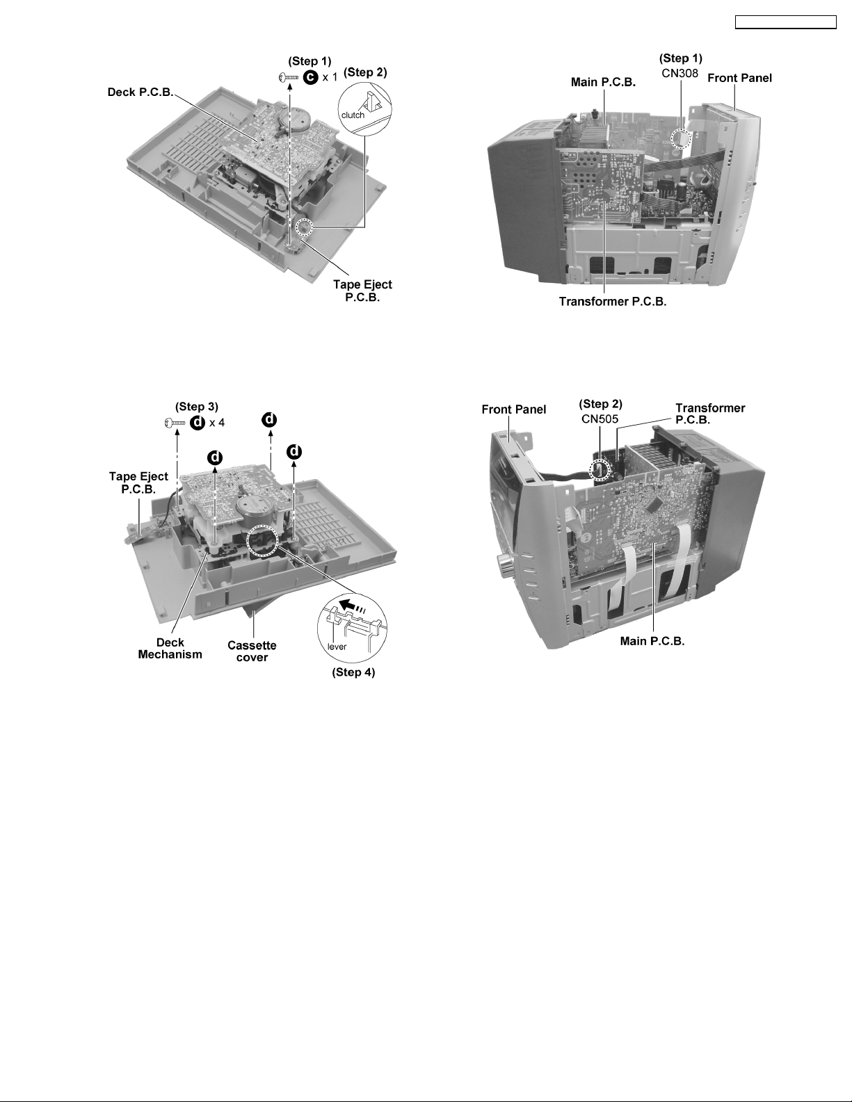
10.4. Disassembly of Deck P.C.B.
and Tape Eject P.C.B.
· Follow the (Step 1) - (Step 6) of item 10.2.
· Follow the (Step 1) - (Step 3) of item 10.3.
14
SA-PM41 P / SA-PM41 PC
Step 1 : Remove 1 screw.
Step 2 : Release the clutch and remove the Tape Eject P.C.B..
Step 3 : Remove 4 screws.
Step 4 : Push the lever as arrow shown to remove the Deck
Mechanism.
Step 1 : Detach the connector CN308.
Step 2 : Detach the connector CN505.
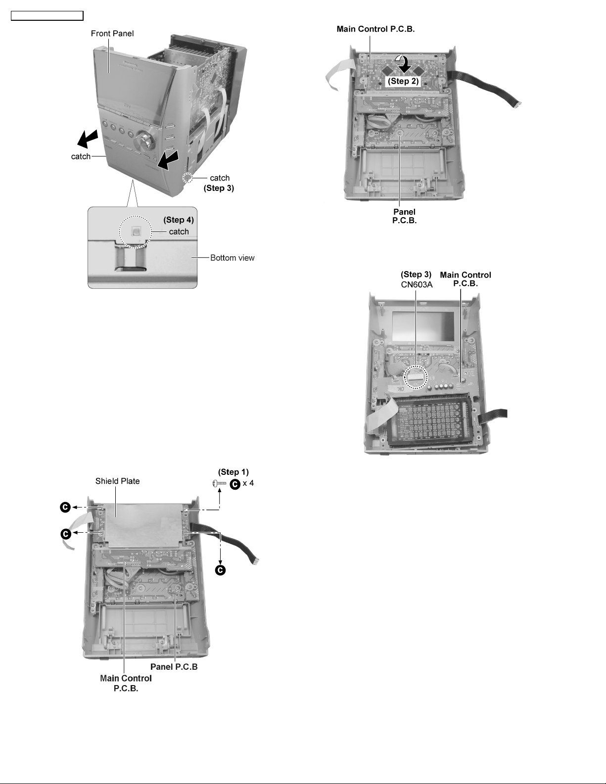
10.5. Disassembly of Front Panel
· Follow the (Step 1) - (Step 6) of item 10.2.
· Follow the (Step 1) - (Step 3) of item 10.3.
15
SA-PM41 P / SA-PM41 PC
Step 2 : Flip the Main Control P.C.B. as arrow shown.
Step 3 : Release 2 catches.
Step 4 : Release the catch at the bottom cabinet and remove
the front panel as arrow shown.
10.6. Disassembly of Main Control
P.C.B., Function P.C.B. and
Power In P.C.B.
· Follow the (Step 1) - (Step 6) of item 10.2.
· Follow the (Step 1) - (Step 3) of item 10.3.
· Follow the (Step 1) - (Step 4) of item 10.5.
· Disasembly of Main Control P.C.B.
Step 3 : Detach the connector CN603A.
· Disasembly of Function P.C.B. and Power In P.C.B.
Step 1 : Remove 4 screws to remove the shield plate.
16
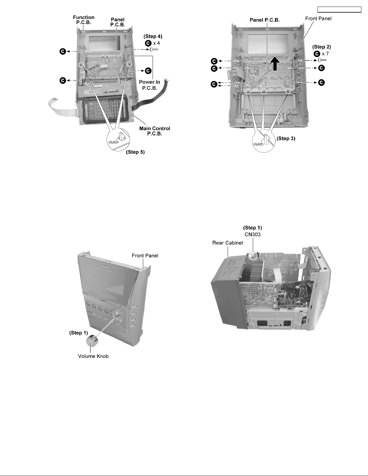
SA-PM41 P / SA-PM41 PC
Step 4 : Remove 4 screws.
Step 5 : Release the 2 clutches and remove Function P.C.B.
and Power In P.C.B. together with Main Control P.C.B..
10.7. Disassembly of Panel P.C.B.
· Follow the (Step 1) - (Step 6) of item 10.2.
· Follow the (Step 1) - (Step 3) of item 10.3.
· Follow the (Step 1) - (Step 4) of item 10.5.
· Follow the (Step 1) - (Step 5) of item 10.6.
Step 2 : Remove 7 screws.
Step 3 : Release 3 clutches and remove the Panel P.C.B. as
arrow shown.
10.8. Disassembly of Rear Cabinet
· Follow the (Step 1) - (Step 6) of item 10.2.
· Follow the (Step 1) - (Step 3) of item 10.3.
Step 1 : Remove the volume knob.
Step 1 : Detach the connector CN303.
17
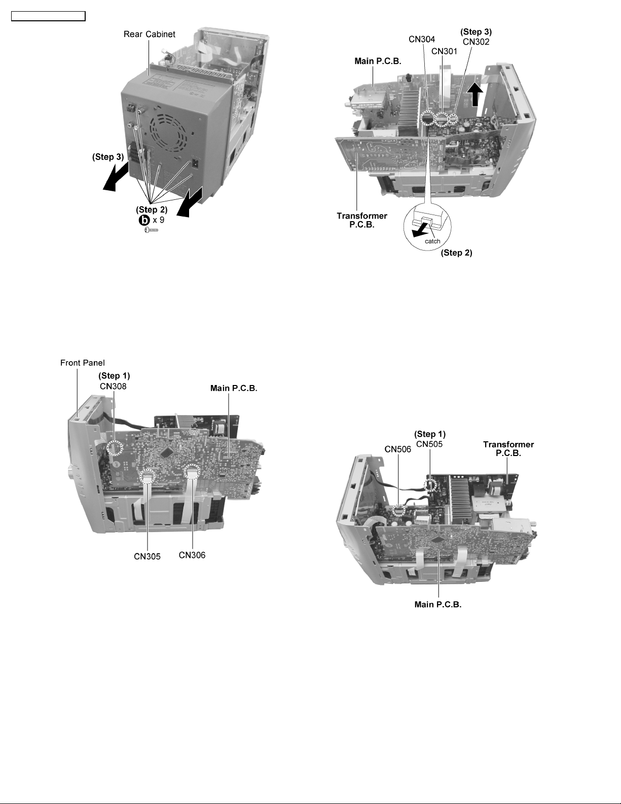
SA-PM41 P / SA-PM41 PC
Step 2 : Remove 9 screws altogether.
Step 3 : Remove the rear cabinet as arrows shown (Be careful
of the catches).
10.9. Disassembly of Main P.C.B.
· Follow the (Step 1) - (Step 6) of item 10.2.
· Follow the (Step 1) - (Step 3) of item 10.3.
· Follow the (Step 1) - (Step 3) of item 10.8.
Step 2 : Release the catch as arrow shown and detach the
connector CN304.
Step 3 : Detach the connectors CN301 and CN302 and pull out
the Main P.C.B. as arrow shown.
10.10. Disassembly of Transformer
P.C.B.
Step 1 : Detach the connector CN308, CN305 and CN306.
· Follow the (Step 1) - (Step 6) of item 10.2.
· Follow the (Step 1) - (Step 3) of item 10.3.
· Follow the (Step 1) - (Step 3) of item 10.8.
Step 1 : Detach the connectors CN505 and CN506.
18

Step 2 : Remove 4 screws and pull out the Transformer P.C.B.
as arrow shown.
SA-PM41 P / SA-PM41 PC
10.11. Disassembly of Tuner Pack
· Follow the (Step 1) - (Step 6) of item 10.2.
· Follow the (Step 1) - (Step 3) of item 10.3.
· Follow the (Step 1) - (Step 3) of item 10.8.
Step 1 : Detach the connector CN101 and remove the tuner
pack as arrow shown.
Step 1 : Remove 4 screws.
Step 2 : Remove the Power P.C.B. as arrow shown (Be careful
of the catch)
10.13. Disassembly of CR16
Mechanism
· Follow the (Step 1) - (Step 6) of item 10.2.
· Follow the (Step 1) - (Step 3) of item 10.3.
· Follow the (Step 1) - (Step 4) of item 10.5.
10.12. Disassembly of Power P.C.B.
· Follow the (Step 1) - (Step 6) of item 10.2.
· Follow the (Step 1) - (Step 3) of item 10.3.
· Follow the (Step 1) - (Step 4) of item 10.5.
· Follow the (Step 1) - (Step 3) of item 10.8.
· Follow the (Step 1) - (Step 3) of item 10.9.
· Follow the (Step 1) - (Step 2) of item 10.10.
Step 1 : Remove 2 screws.
19
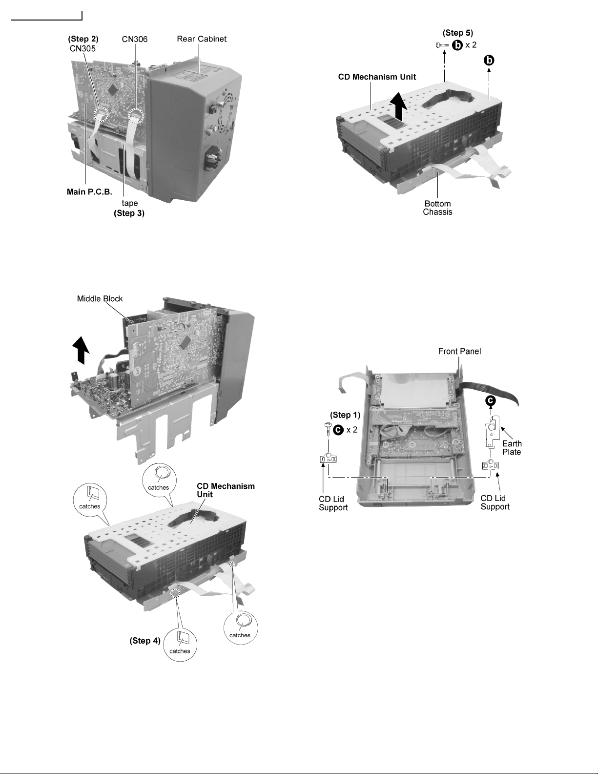
SA-PM41 P / SA-PM41 PC
Step 2 : Detach the connectors CN305 and CN306.
Step 3 : Remove the tape which used to secure the FFC
connectors.
Step 5 : Remove 2 screws and remove the CD Mechanism Unit
from the bottom chassis as arrow shown.
10.14. Replacement of CD Lid
· Follow the (Step 1) - (Step 6) of item 10.2.
· Follow the (Step 1) - (Step 3) of item 10.3.
· Follow the (Step 1) - (Step 4) of item 10.5.
Step 4 : Release the catches and remove the middle block as
arrow shown.
Step 1 : Remove 2 screws 2 CD Lid supports and earth plate.
20
SA-PM41 P / SA-PM41 PC
Step 2 : Push the spring as arrow shown.
Step 3 : Remove the CD lid as arrow shown.
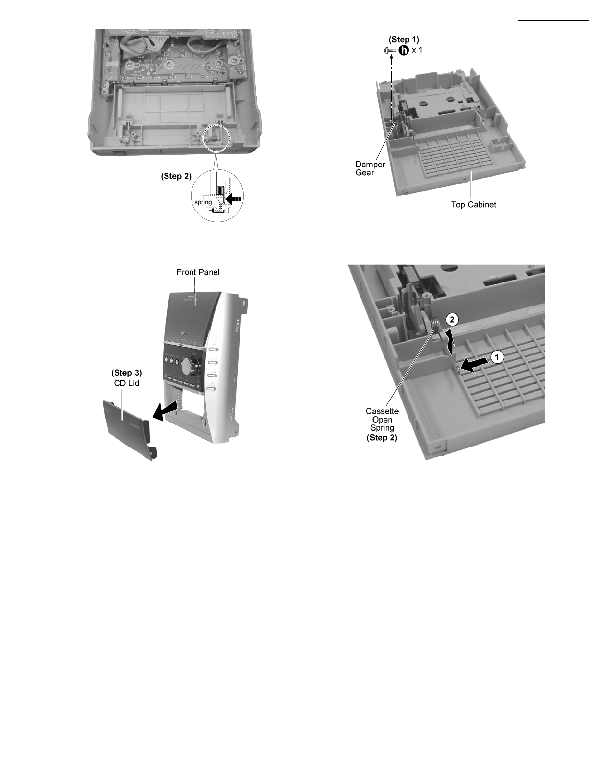
10.15. Replacement of Cassette Lid
· Follow the (Step 1) - (Step 6) of item 10.2.
· Follow the (Step 1) - (Step 3) of item 10.3.
· Follow the (Step 1) - (Step 4) of item 10.4.
Step 1 : Remove 1 screw and the damper gear.
Step 2 : Remove the cassette open spring as arrows shown in
order.
21

SA-PM41 P / SA-PM41 PC
Step 1 : Remove 2 screws.
Step 2 : Remove 2 screws.
Step 3 : Pull both sides cassette holders to the direction of the
arrows shown.
Step 4 : Remove the cassette lid as arrow shown.
10.16. Replacement of the Power IC
and Transistors
Step 3 : Unsolder the Power IC500.
Step 4 : Unsolder the Transistor Q501 and Q502.
· Follow the (Step 1) - (Step 6) of item 10.2.
· Follow the (Step 1) - (Step 3) of item 10.3.
· Follow the (Step 1) - (Step 4) of item 10.5.
· Follow the (Step 1) - (Step 3) of item 10.8.
· Follow the (Step 1) - (Step 3) of item 10.9.
· Follow the (Step 1) - (Step 2) of item 10.10.
· Follow the (Step 1) - (Step 2) of item 10.12.
22
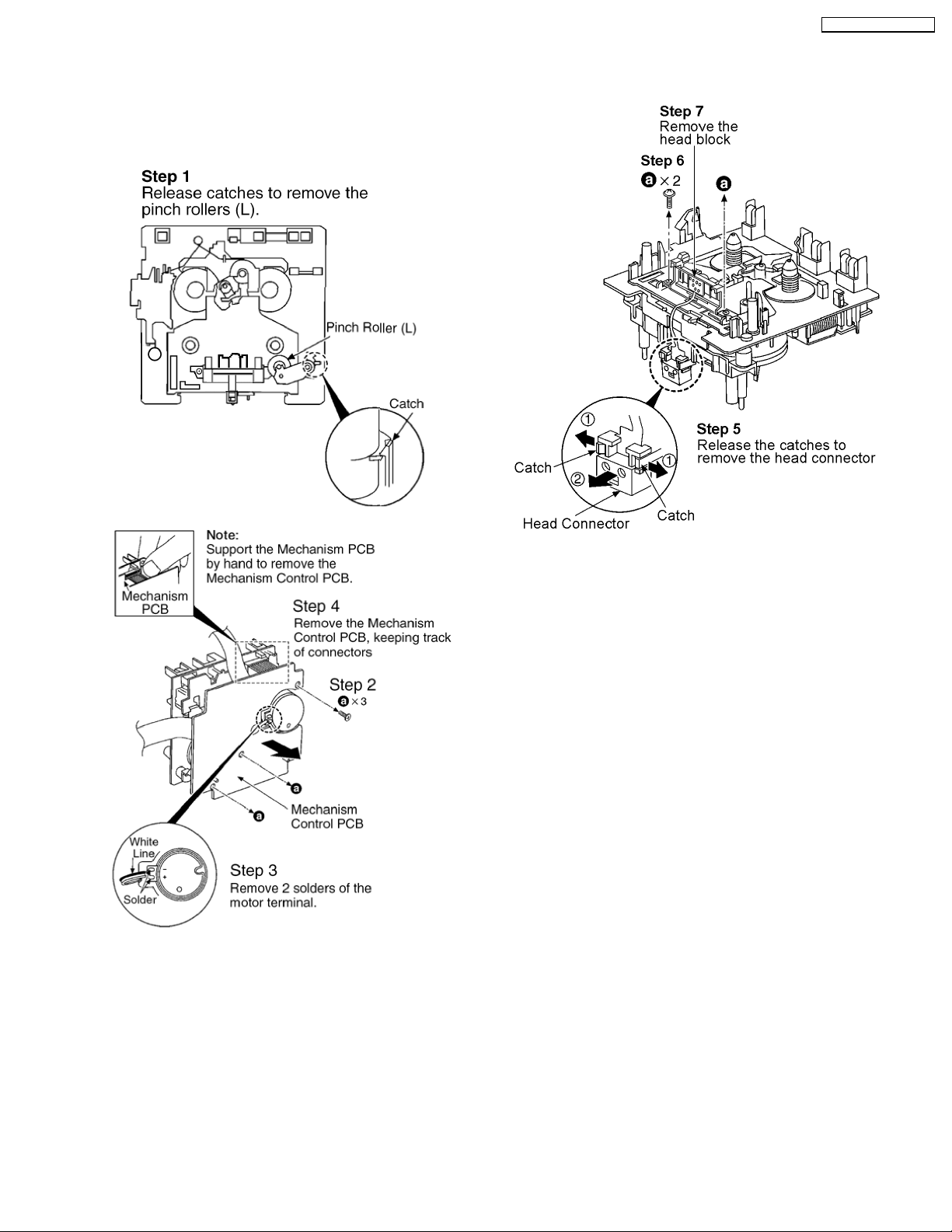
10.17. Procedure for Replacing Pinch Roller and Head Block (Cassette
Mechanism Unit)
· Follow the (Step 1) - (Step 6) of Item 10.2.
· Follow the (Step 1) - (Step 3) of Item 10.3.
· Follow the (Step 1) - (Step 4) of Item 10.4.
SA-PM41 P / SA-PM41 PC
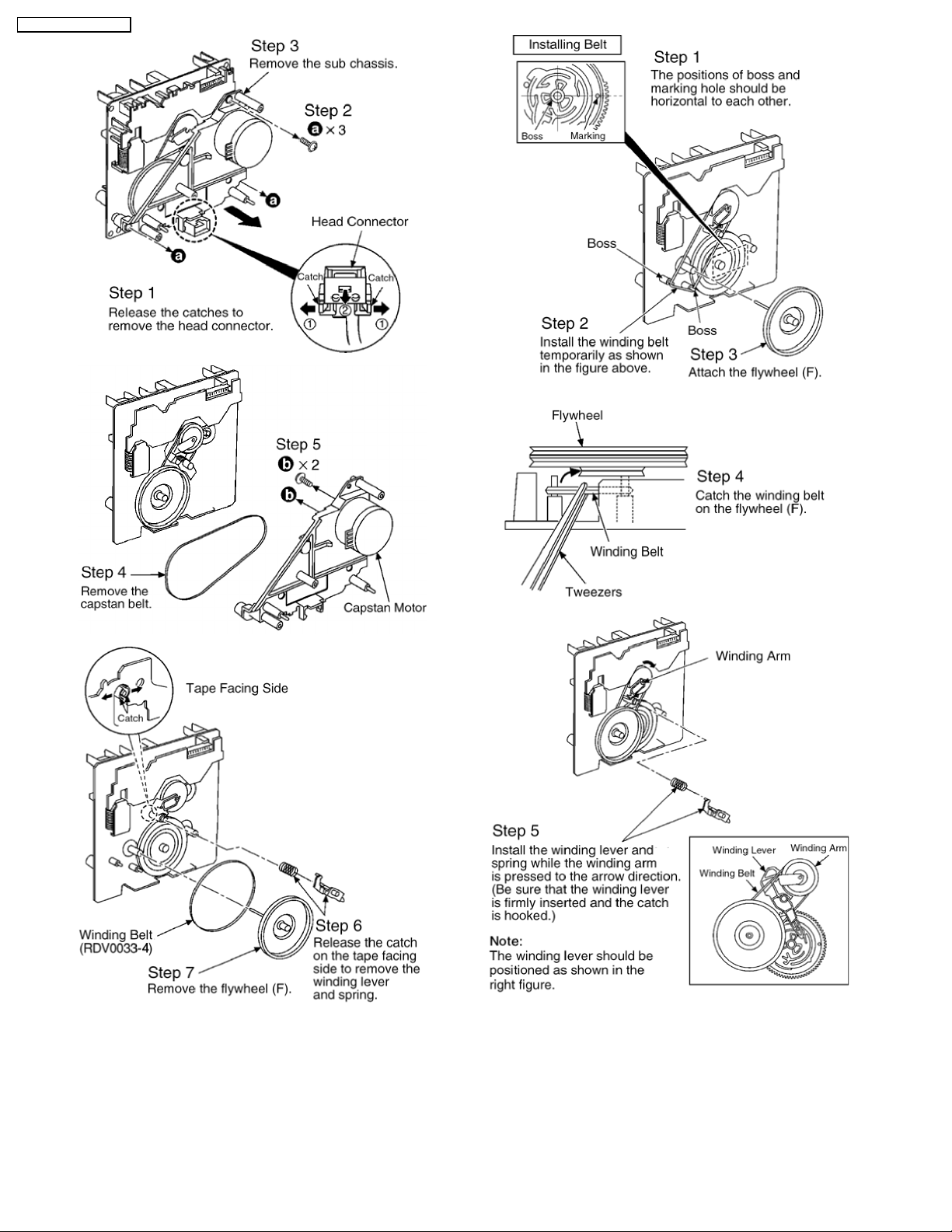
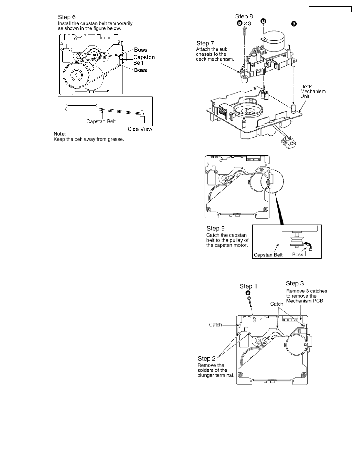
10.18. Procedure for Replacing Motor, Capstan Belt A, Capstan Belt B, and
Winding Belt (Cassette Mechanism Unit)
· Follow the (Step 1) - (Step 6) of Item 10.2.
· Follow the (Step 1) - (Step 3) of Item 10.3.
· Follow the (Step 1) - (Step 4) of Item 10.4.
· Follow the (Step 1) - (Step 5) of Item 10.17.
23
SA-PM41 P / SA-PM41 PC
24
SA-PM41 P / SA-PM41 PC
10.19. Procedure for Replacing Parts on Mechanism PCB
· Follow the (Step 1) - (Step 6) of Item 10.2.
· Follow the (Step 1) - (Step 3) of Item 10.3.
· Follow the (Step 1) - (Step 4) of Item 10.4.
· Follow the (Step 1) - (Step 5) of Item 10.17.
10.20. Disassembly of CR16 Mechanism
· Follow the (Step 1) - (Step 6) of Item 10.2.
· Follow the (Step 1) - (Step 3) of Item 10.3.
· Follow the (Step 1) - (Step 4) of Item 10.5.
· Follow the (Step 1) - (Step 3) of Item 10.8.
· Follow the (Step 1) - (Step 5) of Item 10.13.
25

SA-PM41 P / SA-PM41 PC
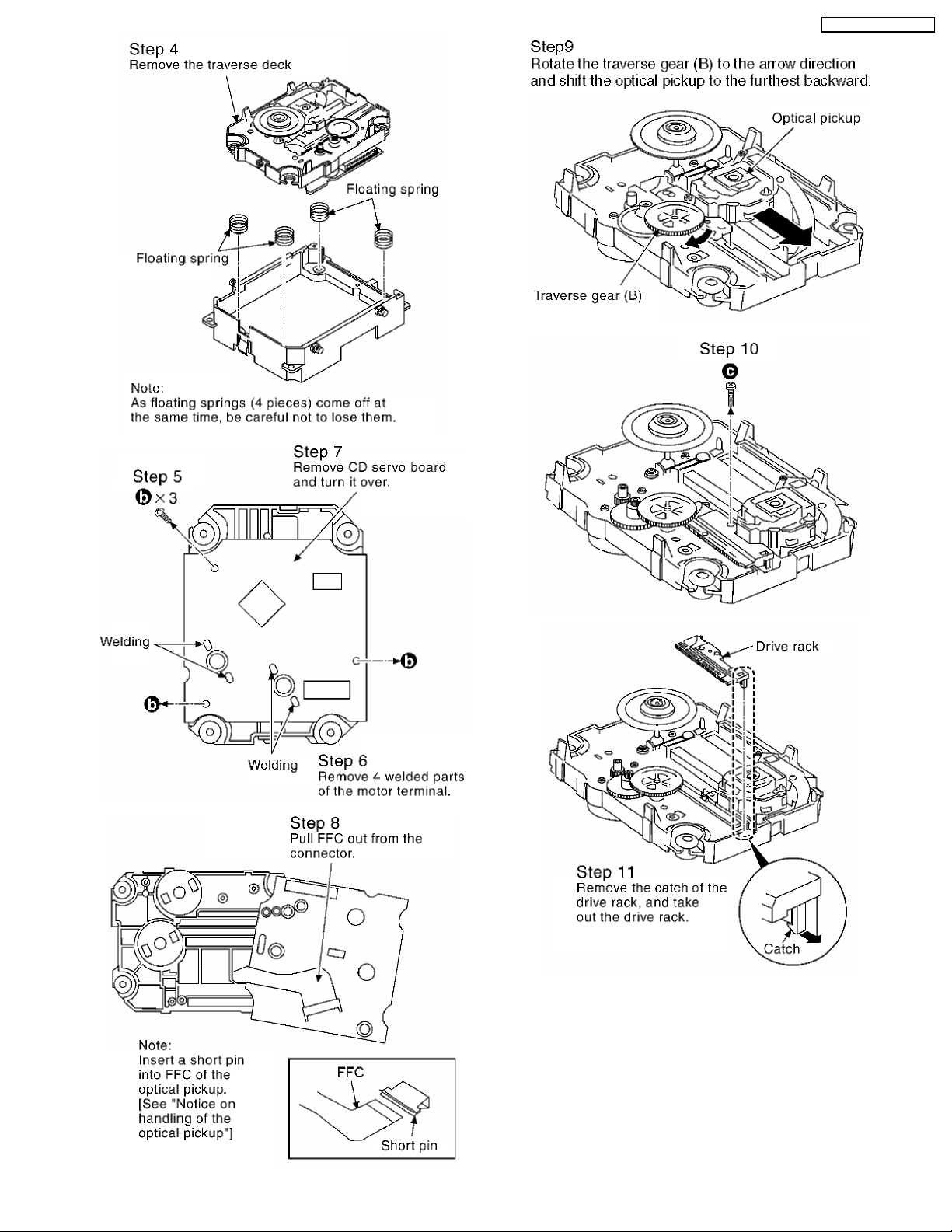
10.21. Replacement of optical pickup unit (CD mechanism)
· Follow the (Step 1) - (Step 6) of Item 10.2.
· Follow the (Step 1) - (Step 3) of Item 10.3.
· Follow the (Step 1) - (Step 4) of Item 10.5.
· Follow the (Step 1) - (Step 3) of Item 10.8.
· Follow the (Step 1) - (Step 5) of Item 10.13.
· Follow the (Step 1) - (Step 2) of Item 10.20.
26
SA-PM41 P / SA-PM41 PC
27

SA-PM41 P / SA-PM41 PC
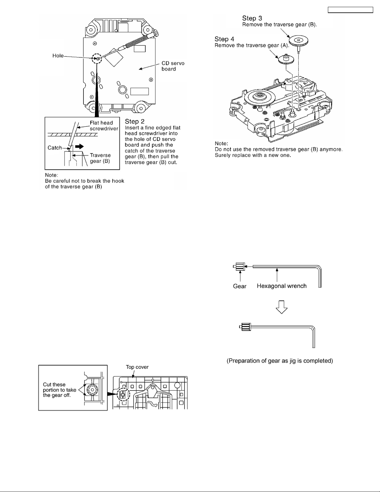
10.22. Replacement of a traverse gear A and a traverse gear B
· Follow the (Step 1) - (Step 6) of Item 10.2.
· Follow the (Step 1) - (Step 3) of Item 10.3.
· Follow the (Step 1) - (Step 4) of Item 10.5.
· Follow the (Step 1) - (Step 3) of Item 10.8.
· Follow the (Step 1) - (Step 5) of Item 10.13.
· Follow the (Step 1) - (Step 2) of Item 10.20.
· Follow the (Step 1) - (Step 12) of Item 10.21.
28
SA-PM41 P / SA-PM41 PC
10.23. Procedure for removing CD loading mechanism
1. Turn off by pressing power S W in the body.
2. Unplug AC power cord after the indication of [GOOD-BYE],
then disassemble the body.
3. Disassemble the body, and take out CD loading
mechanism.
4. Perform disassembly according to the following procedure
for disassembly.
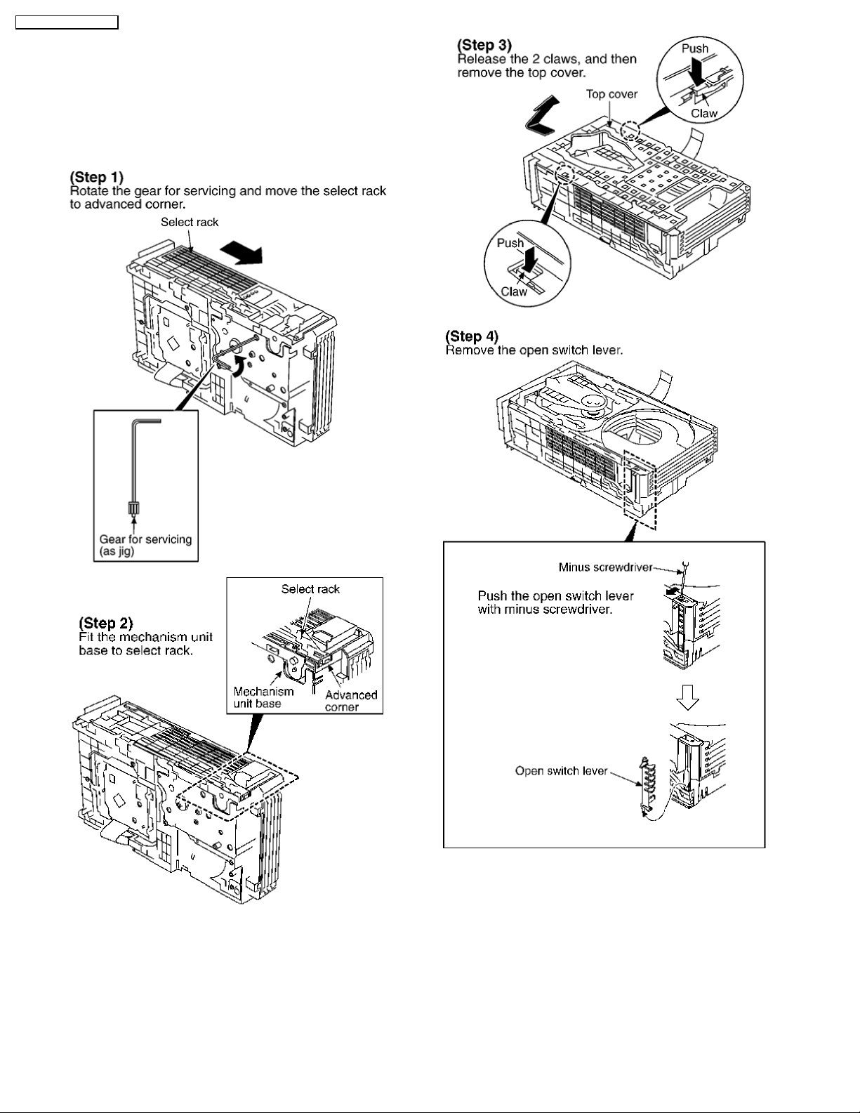
10.24. CR16 mechanism disassembly procedure
10.24.1. Gear for servicing information
· This unit has a gear which used for checking items
(open/close of disc tray, up/down operation of traverse unit
by manually) when servicing. (For gear information, that is
described on the items for disassembly procedures.)
· For preparation of gear (for servicing), perform the
procedures as follows.
· In case of re-servicing the same set, the “ gear for servicing”
may be took off because it had been used. So, the “gear for
servicing” must be stored.
1. Remove the gear attached to top cover of CD loading
mechanism.
2. Insert the hexagonal wrench (2.5mm) into the gear.
29
SA-PM41 P / SA-PM41 PC
10.24.2. Replaceme nt for the disc tray
· Follow the (Step 1) - (Step 6) of Item 10.2.
· Follow the (Step 1) - (Step 3) of Item 10.3.
· Follow the (Step 1) - (Step 4) of Item 10.5.
· Follow the (Step 1) - (Step 3) of Item 10.8.
· Follow the (Step 1) - (Step 5) of Item 10.13.
30
 Loading...