

Panasonic SAPM-33-EE Service manual
A
CD Stereo System
SA-PM33EE
Colour
(S)... Silver Type
ORDER NO. MD0603074C3
Specification
RMS OUTPUT POWER both channel driven simultaneously
10% total harmonic distortion 20 W per channel (6 Ω)
Input impedance
MUSIC PORT 250 mV 12 kΩ
Output impedance
HEADPHONE 16 to 32 Ω
Phone jack
Terminal Stereo, 3.5 mm
Music Port input jack
Terminal Stereo, 3.5 mm
n FM Tuner Section
Frequency range 87.50 to 108.00 MHz
(50 kHz step)
Sensitivity 3.8 µV (IHF)
S/N 26 dB 1.2 µV
ntenna terminals 75 Ω (unbalanced)
Preset station FM 15 stations
AM 15 stations
n AM Tuner Section
Frequency range 522 to 1629 kHz
(9 kHz steps)
520 to 1630 kHz
(10 kHz steps)
Sensitivity
S/N 20 dB (at 999 kHz) 1122 µV/m
n Cassette Deck Section
Track system 4-track, 2-channel
Heads
Record/playback Solid permalloy head
Erasure Double gap ferrite head
Motor DC servo motor
Recording system AC bias 100 kHz
Erase system AC erase 100 kHz
Tape speed 4.8 cm/s
Overall frequency response (+3 dB, -6 dB) at DECK OUT
Normal 35 Hz to 14 kHz
S/N RATIO 47 dB (A weighted)
Wow and flutter 0.08% (WRMS)
Fast-forward and rewind time Approx. 120 seconds with C-60
cassette tape
n CD Section
Disc played [8 cm or 12 cm]
(1) CD-Audio (CD-DA)
(2) CD-R/RW (CD-DA, MP3 formatted disc)
(3) MP3
Sampling frequency
CD 44.1 kHz
MP3 32 kHz, 44.1 kHz, 48 kHz
© 2006 Matsushita Electric Industrial Co. Ltd.. All
rights reserved. Unauthorized copying and
distribution is a violation of law.
A
SA-PM33EE
Bit rate
MP3 32 kbps to 384 kbps
Decoding 16/20/24 bit linear
Pickup
Beam source Semiconductor laser
Wavelength 785 nm
Laser power CLASS 1
udio output (Disc)
Number of channels 2 channel
Frequency response 20 Hz to 20 kHz (+1, -2dB)
Wow and flutter Below measurable limit
Digital filter 8fs
D/A converter MASH (1 bit DAC)
n General
Power supply AC 230 V, 50 Hz
Power consumption 63 W
Dimensions (W x H x D) 165 x 227 x 327 mm
Mass 3.5 kg
Operating temperature range +5 to +35°C
Operation humidity range 5 to 90% RH (no condensation)
Power consumption in standby
mode
Notes :
1. Specifications are subject to change without notices. Mass and
dimensions are approximate.
2. Total harmonic distortion is measured by the digital spectrum
analyzer.
n System : SC-PM33EE-S
Music center: SA-PM33EE-S
Speaker: SB-PM33EG-M
0.8 W
CONTENTS
Page Page
1 Safety Precautions 4
1.1. General Guidelines
1.2. Before Repair and Adjustment
1.3. Protection Circuitry
2 Prevention of Electro Static Discharge (ESD) to
Electrostatically Sensitive (ES) Devices
3 Precaution of Laser Diode
4 Handling Precautions For Traverse Deck
5 Handling the Lead-free Solder
5.1. About lead free solder (PbF)
6 Accessories
7 Operating Instructions Procedures
7.1. Main Unit & Remote Control Operation
7.2. Disc Information
8 Self diagnosis and special mode setting
8.1. Special Mode Table
8.2. Error Code Table
9 Assembling and Disassembling
9.1. Caution
9.2. Disassembly flow chart
9.3. Main Parts Location Diagram
9.4. Disassembly of Side Panel L & R
9.5. Disassembly of Top Cabinet Unit
9.6. Disassembly of Deck Mechanism and Tape Eject P.C.B.
9.7. Disassembly of Headphone P.C.B.
9.8. Disassembly of Front Panel
9.9. Disassembly of Panel P.C.B.
9.10. Disassembly of Rear Panel
9.11. Disassembly of Tuner Pack
10
11
11
12
13
13
17
19
19
20
21
22
22
23
23
23
24
25
25
4
5
5
6
7
8
9
9
9.12. Disassembly of Main P.C.B.
9.13. Disassembly of Power P.C.B.
9.14. Disassembly of Speaker Terminal P.C.B.
9.15. Disassembly of Transforme r P.C.B.
9.16. Disassembly of CD Mechanism
9.17. Disassembly of Cassette Lid
9.18. Disassembly of Traverse Unit, Driving Gear, and Cam
Gear (CD Mechanism Unit)
9.19. Disassembly of Optical Pickup (CD Mechanism Unit)
9.20. Disassembly of Traverse Gear A and Traverse Gear B
(CD Mechanism Unit)
9.21. Disassembly of Pinch Roller and Head Block (Deck
Mechanism Unit)
9.22. Disassembly of Motor, Capstan Belt A, Capstan Belt B,
and Winding Belt (Deck Mechanism Unit)
9.23. Disassembly of Deck Mechanism P.C.B.
9.24. Handling of cassette tape jam
10 Service Fixture and Tools
11 Service Positions
11.1. Checking and Repairing of Deck, Deck Mechanism,
Headphone P.C.B. and Tape Eject P.C.B.
11.2. Checking and Repairing of Panel P.C.B.
11.3. Checking and Repairing of Tuner Pack P.C.B.
11.4. Checking and Repairing of Transformer P.C.B.
11.5. Checking and Repairing of Main P.C.B.
11.6. Checking and Repairing of CD Mechanism P.C.B.
11.7. Checking and Repairing of Speaker Terminal P.C.B.
11.8. Checking and Repairing of Power P.C.B.
25
26
27
27
27
28
29
32
33
34
34
36
36
37
37
37
38
39
40
41
42
43
44
2

SA-PM33EE
12 Procedure for Checking Operation of Individual Parts of Deck
Mechanism Unit
12.1. Operation Check with Cassette Tape
12.2. Operation Check without Cassette Tape
13 Measurement And Adjustments
13.1. Cassette Deck Section
14 Voltage Measurement and Waveform Chart
14.1. Voltage Measurement
14.2. Waveform
15 Wiring Connection Diagram
16 Block Diagram
17 Notes of Schematic Diagram
18 Schematic Diagram
18.1. CD Servo Circuit
18.2. Main Circuit and Tuner Extent Circuit
18.3. Panel Circuit
45
45
45
47
47
49
49
53
55
57
61
63
63
64
66
18.4. Deck Circuit, Deck Mechanism Circuit and Tape Eject
Circuit
18.5. Power Circuit
67
68
18.6. Transformer Circuit, Headphone Circuit and Speaker
Terminal Circuit
19 Printed Circuit Board
69
71
19.1. CD Servo P.C.B.
19.2. Main P.C.B and Tuner Extent P.C.B.
19.3. Panel P.C.B.
19.4. Deck P.C.B, Deck Mechanism P.C.B and Tape Eject
P.C.B.
19.5. Power P.C.B and Speaker Terminal P.C.B.
19.6. Transformer P.C.B and Headphone P.C.B.
20 Illustration of IC's, Transistors and Diodes
21 Terminal Function of IC's
21.1. IC7001 (MN6627954MA) IC SERVO
PROCESSOR/DIGITAL SIGNAL PROCESSOR/DIGITAL
FILTER D/A CONVERTER
21.2. IC7002 (BA5948FPE2) IC 4CH Drive
21.3. IC803 (MN101C49GHD) MICROPROCESSOR
22 Troubleshooting Flowchart (CD Section Circuit)
23 Exploded Views
23.1. Cabinet Parts Location
23.2. Cassette Deck (RAA4402-1S) & Traverse Deck Part
Location
23.3. Packaging
24 Replacement Parts List
71
72
73
74
75
76
77
78
78
79
79
81
83
83
84
85
87
3

SA-PM33EE
1 Safety Precautions
1.1. General Guidelines
1. When servicing, observe the original lead dress. If a short circuit is found, replace all parts which have been overheated or
damaged by the short circuit.
2. After servicing, ensure that all the protective devices such as insulation barriers, insulation papers shields are properly installe d.
3. After servicing, check for leakage current checks to prevent from being exposed to shock hazards.
1.1.1. Leakage Current Cold Check
1. Unplug the AC cord and connect a jumper between the two prongs on the plug.
2. Using an ohmmeter measure the resistance value, between the jumpered AC plug and each exposed metallic cabinet part on
the equipment such as screwheads, connectors, control shafts, etc. When the exposed metallic part has a return path to the
chassis, the reading should be between 1MΩ and 5.2Ω.
When the exposed metal does not have a return path to the chassis, the reading must be
.
Figure 1
1.1.2. Leakage Current Hot Check (See Figure 1)
1. Plug the AC cord directly into the AC outlet. Do not use an isolation transformer for this check.
2. Connect a 1.5kΩ, 10 watts resistor, in parallel with a 0.15µF capacitors, between each exposed metallic part on the set and a
good earth ground such as a water pipe, as shown in Figure 1.
3. Use an AC voltmeter, with 1000 ohms/volt or more sensitivity, to measure the potential across the resistor.
4. Check each exposed metallic part, and measure the voltage at each point.
5. Reverse the AC plug in the AC outlet and repeat each of the above measurements.
6. The potential at any point should not exceed 0.75 volts RMS. A leakage current tester (Simpson Model 229 or equivalent) may
be used to make the hot checks, leakage current must not exceed 1/2 milliamp. should the measurement is outside of the limits
specified, there is a possibility of a shock hazard, and the equipment should be repaired and re-checked before it is returned
to the customer.
4

SA-PM33EE
1.2. Before Repair and Adjustment
Disconnect AC power, discharge Power Supply Capacitors C501, C601, C839, C840, C844, C862, C868, C909, C910, C911 &
C923 through a 10Ω, 1W resistor to ground.
DO NOT SHORT-CIRCUIT DIRECTLY (with a screwdriver blade, for instance), as this may destroy solid state devices.
After repairs are completed, restore power gradually using a variac, to avoid overcurrent.
· Current consumption at AC 230 V, 50 Hz in NO SIGNAL mode should be ~150 mA.
1.3. Protection Circuitry
The protection circuitry may have operated if either of the following conditions are noticed:
· No sound is heard when the power is turned on.
· Sound stops during a performance.
The function of this circuitry is to prevent circuitry damage if, for example, the positive and negative speaker connection wires are
"shorted", or if speaker systems with an impedance less than the indicated rated impedance of the amplifier are used.
If this occurs, follow the procedure outlines below:
1. Turn off the power.
2. Determine the cause of the problem and correct it.
3. Turn on the power once again after one minute.
Note:
When the protection circuitry functions, the unit will not operate unless the power is first turned off and then on again.
5

SA-PM33EE
2 Prevention of Electro Static Discharge (ESD) to
Electrostatically Sensitive (ES) Devices
Some semiconductor (solid state) devices can be damaged easily by electricity. Such components commonly are called
Electrostatically Sensitive (ES) Devices. Examples of typical ES devices are integrated circuits and some field-effect transistors and
semiconductor “chip” components. The following techniques should be used to help reduce the incidence of component damage
caused by electro static discharge (ESD).
1. Immediately before handlin g any semiconductor component or semiconductor-equiped assembly, drain off any ESD on your
body by touching a known earth ground. Alternatively, obtain and wear a commercially available discharging ESD wrist strap,
which should be removed for potential shock reasons prior to applyin g power to the unit under test.
2. After removing an electrical assembly equiped with ES devices, place the assembly on a conductive surface such as aluminium
foil, to prevent electrostatic charge build up or exposure of the assembly.
3. Use only a grounded-tip soldering iron to solder or unsolder ES devices.
4. Use only an anti-static solder remover device. Some solder removal devices not classified as “anti-static (ESD protected)” can
generate electrical charge to damage ES devices.
5. Do not use freon-propelled chemicals. These can generate electrical charges sufficient to damage ES devices.
6. Do not remove a replacement ES device from its protective package until immediately before you are ready to install it. (Most
replacement ES devices are packaged with leads electrically shorted together by conductive foam, aluminium foil or
comparable conductive material).
7. Immediately before removing the protective material from the leads of a replacement ES device, touch the protective material
to the chassis or circuit assembly into which the device will be installed.
Caution
Be sure no power is applied to the chassis or circuit, and observe all other safety precautions.
8. Minimize body motions when handling unpackaged replacement ES devices. (Otherwise harmless motion such as the brushing
together of your clothes fabric or the lifting of your foot from a carpeted floor can generate static electricity (ESD) sufficient to
damage an ES device).
6
SA-PM33EE
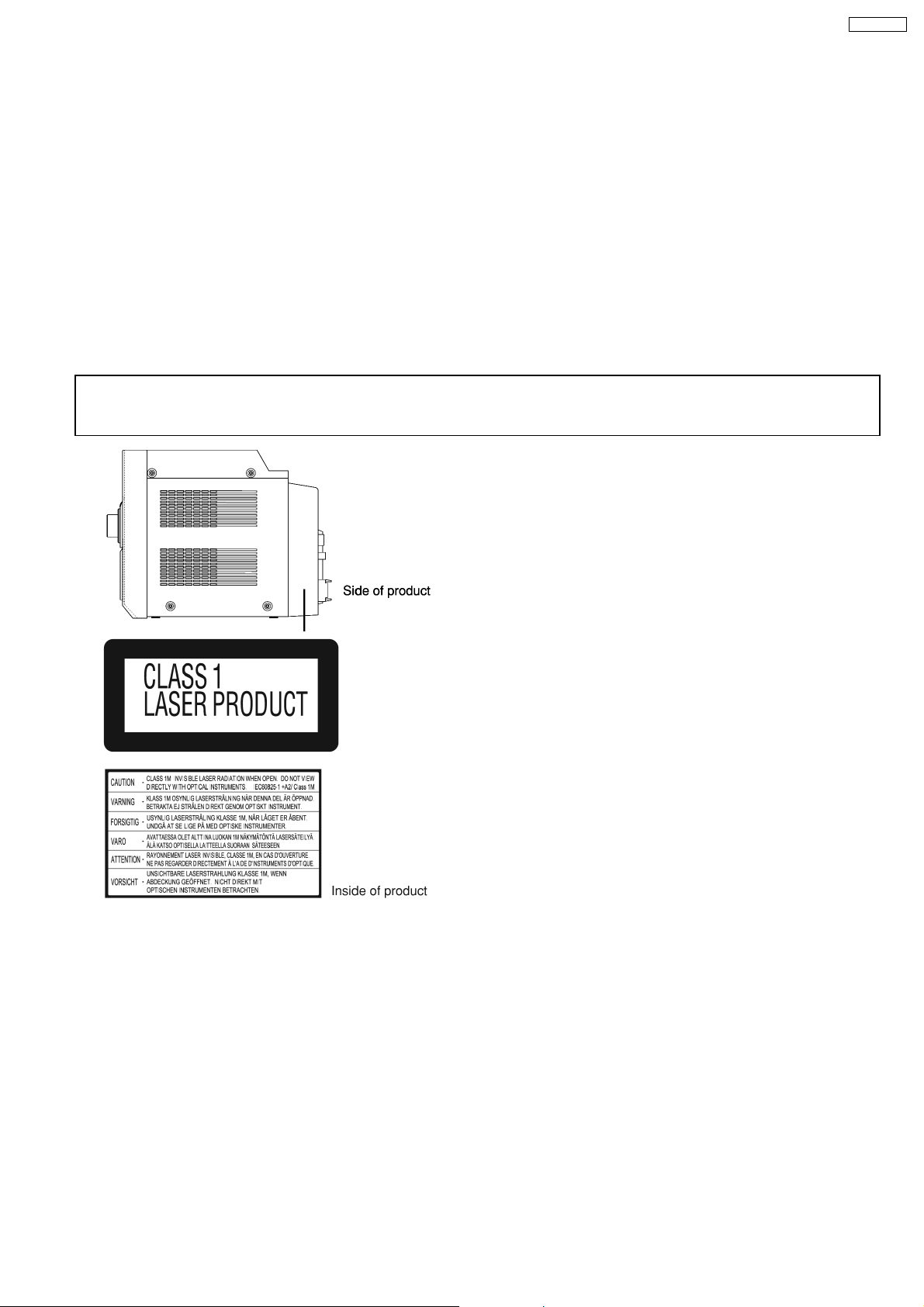
3 Precaution of Laser Diode
CAUTION:
This unit utilizes a class 1 laser.
Invisible laser radiation is emitted from the optical pickup lens.
When the unit is turned on:
1. Do not look directly into the pick up lens.
2. Do not use optical instruments to look at the pick up lens.
3. Do not adjust the preset variable resistor on the pickup lens.
4. Do not disassemble the optical pick up unit.
5. If the optical pick up is replaced, use the manufacturer’s specified replacement pick up only.
6. Use of control or adjustments or performance of procedures other than those specified herein may result in hazardous radiation
exposure.
CAUTION!
THIS PRODUCT UTILIZES A LASER.
USE OF CONTROLS OR ADJUSTMENTS OR PERFORMANCE OF PROCEDURES OTHER THAN THOSE SPECIFIED HEREIN MAY RESULT
IN HAZARDOUS RADIATION EXPOSURE.
7

SA-PM33EE
4 Handling Precautions For Traverse Deck
The laser diode in the traverse deck (optical pickup) may break
down due to potential difference caused by static electricity of
clothes or human body.
So, be careful of electrostatic breakdown during repair of the
traverse deck (optical pickup).
l Handling of CD traverse deck (optical pickup)
1. Do not subject the traverse deck (optical pickup) to
static electricity as it is extremely sensitive to electrical
shock.
2. The short land between the No.4 (LD) and No.5 (GND)
pins on the flexible board (FFC) is shorted with a solder
build-up to prevent damage to the laser diode.
3. Take care not to apply excessive stress to the flexible
board (FFC board) (Fig 4.1).
4. Do not turn the variable resistor (laser power
adjustment). It has already been adjusted.
Fig 4.1
l Grounding for electrostatic breakdown prevention
1. Human body grounding (Fig 4.2)
Use the anti-static wrist strap to discharge the static
electricity from your body.
2. Work table grounding (Fig 4.2)
Put a conductive material (sheet) or steel sheet on the
area where the traverse deck (optical pickup) is placed,
and ground the sheet.
Caution :
The static electricity of your clothes will not be grounded
through the wrist strap. So, take care not to let your
clothes touch the traverse deck (optical pickup).
Fig 4.2
Caution when Replacing the Optical Pickup :
The traverse has a short point shorted with solder to protect
the laser diode against electrostatics breakdown. Be sure to
remove the solder from the short point before making
connections.
8

SA-PM33EE
5 Handling the Lead-free Solder
5.1. About lead free solder (PbF)
Distinction of PbF P.C.B.:
P.C.B.s (manufacture d) using lead free solder will have a PbF stamp on the P.C.B.
Caution:
· Pb free solder has a higher melting point than standard solder; Typically the melting point is 50 - 70°F (30 - 40°C) higher. Please
use a high temperature soldering iron. In case of soldering iron with temperature control, please set it to 700 ± 20°F (370 ±
10°C).
· Pb free solder will tend to splash when heated too high (about 1100°F/600°C).
· W hen soldering or unsoldering, please completely remove all of the solder on the pins or solder area, and be sure to heat the
soldering points with the Pb free solder until it melts enough.
9

SA-PM33EE
6 Accessories
Note : Refer to Packing Materials & Accessories (Section 24) for part number.
Remote control
AC cord
FM indoor
antenna
AM loop antenna
10

7 Operating Instructions Procedures
7.1. Main Unit & Remote Control Operation
SA-PM33EE
11

SA-PM33EE
7.2. Disc Information
12
8 Self diagnosis and special mode setting
This unit is equipped with features of self-diagnostic & special mode setting for checking the functions & reliability.
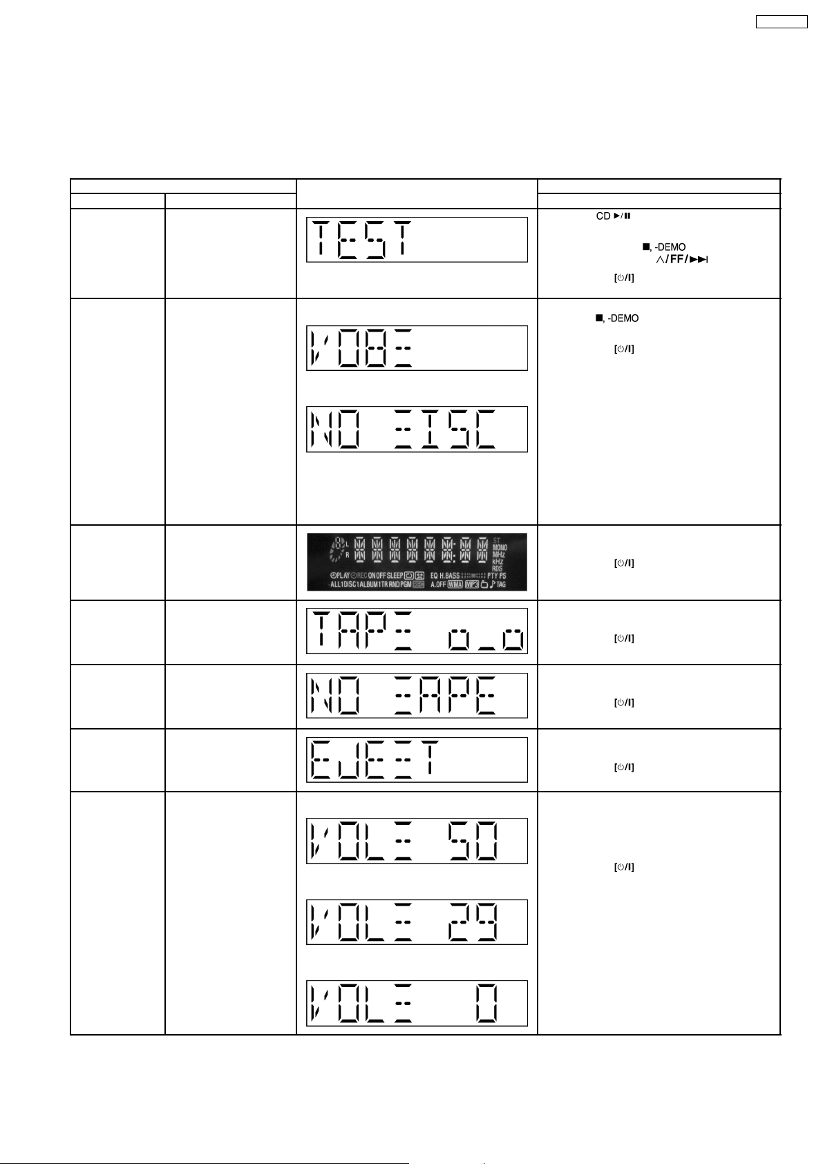
8.1. Special Mode Table
Below is the various special modes for checking:-
Item FL Display Key Operation
Mode Name Description Front Key
Self -Diagnostic
Mode
Doctor Mode To enter into Doctor
To enter into self
diagnostic checking for
main unit.
Mode for checking of
various items and
displaying EEPROM and
firmware version.
(For more information,
refer to section 8.1.2)
Note: The microprocessor version as
shown is an example. It
will be revise when there
is an updates.
1.
2.
The Check Sum of EEPROM and firmware
version will be display for 1 sec.
1. Select [ ] for CD mode (Ensure no
tape or CD inserted).
2. Press and hold [
seconds follow by [
To exit, press
remote control.
In any mode:
1. Press [
by [4] and [7] on remote control.
To exit, press
remote control.
button on main unit or
] button on main unit follow
button on main unit or
]button for 2
].
SA-PM33EE
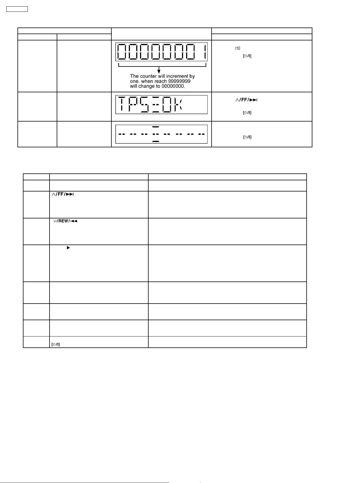
FL Display Test To check the FL
CD to Tape
Recording Test
Mode
Tape Recording
and Playing
Tape Eject test To check on the tape
Volume Setting To Forced Volume
segments display (All
segments will light up)
To Inspect the recording
process from CD to
TAPE for the unit.
(For more information,
refer to section 8.1.3)
To Inspect the Tape
recording and playing is
process for unit.
(For more information,
refer to section 8.1.4)
eject function.
Setting.
* ROM correction
** Firmware version No:
1.
2.
In doctor mode:
1. Press [DIMMER] button on remote control.
To exit, press
remote control.
In doctor mode:
1. Press [4] button on remote control.
To exit, press
remote control.
In doctor mode:
1. Press [5] button on remote control.
To exit, press
remote control.
In doctor mode:
1. Press [6] button on remote control.
To exit, press
remote control.
In doctor mode:
1. Press [7] button on remote control.
2. Press [8] button on remote control.
3. Press [9] button on remote control.
To exit, press
remote control.
button on main unit or
button on main unit or
button on main unit or
button on main unit or
button on main unit or
3.
13
SA-PM33EE
Item FL Display Key Operation
Mode Name Description Front Key
Traverse Test To determine the
reliability of CD unit.
In doctor Mode:
1. Press [
To exit, press
remote control.
], [1], [2] button on remote control.
button on main unit or
TPS To check FF TPS for
deck.
(For more information,
refer to section 8.1.5)
Cold Start To activate cold start ipon
next AC power up.
In doctor mode:
1. Press [
control.
To exit, press
remote control.
In doctor mode:
1. Press [SLEEP] button on remote control.
To exit, press
remote control.
8.1.1. Cassette Mechanism Self-Diagnostic Mode
Below is information of the checking of cassette deck mechanism
No. Operation Procedures Micon operation & processing
1 C-mecha Abnormal Detection shall be
executed for DECK.
2 [ ] key is pressed, after loading in a
NORMAL type cassette with the recording tab
on the left side removed.
3 [ ] key is pressed, after loading a
NORMAL, CrO2, METAL type cassette with
the recording tab on the right side removed.
4 [TAPE ] Key is pressed, after loading in a
NORMAL, CrO2, METAL type cassette (
cassette for TPS checking purposes and with
both recording tabs intact ).
5 [REC] key is pressed, after loading in a
NORMAL type cassette ( with both recording
tabs intact )
6 Self-diagnostic mode is stopped by pressing
the [n] Key.
7 To clear all the abnormalities in the memory,
press the [n] Key for more than 5 Sec while
the self-diagnostic mode is stopped.
8 To cancel the self-diagnostic mode press the
Key.
Check that all DECK mechanism leaf SW is in OFF state.
FF shall be executed for 2 sec, after which STOP.
Check the following.
{ F.REC INH SW } is OFF
{ HALF SW } is ON
Reel pulse toggles between H & L.
REW shall be executed for 2 sec, after which STOP.
Check the following.
{ F.REC INH SW } is ON
{ HALF SW } is ON
Reel pulse toggles between H & L.
TPS operation is executed. Check the following.
{ F.REC INH SW } is ON
{ HALF SW } is ON
TPS signal changes.
After checking TPS, it shall STOP.
If TPS checking is completed at TAPE END, it is considered as TPS
abnormal.
REC operation shall not be executed.
Check the following.
{ F.REC INH SW } is ON
{ HALF SW } is ON
LCD shall display the abnormality item code, when the STOP key is pressed,
it shall display the abnormality item code in the following sequence.
[ TEST H 0 1] [ TEST H 0 2] [ TEST H 0 3]
At this time, all the abnormalities item in the memory is cleared and is
displayed on the LCD.[ C L E A R ] display for 1 Sec. then,[ TEST ] is
displayed.
POWER is OFF.At the next POWER ON, normal operation shall be executed.
] button on remote
button on main unit or
button on main unit or
· If RAM check error occurs during microcomputer reset, COLDSTART shall be executed and all the error memory shall be
cleared during RAM initialization.
8.1.2. EEPROM Checksum (ROM correction)
Purpose : To check for micro-processor firmware version & EEPROM check (ROM correction).
Below is the procedures for this mode.
Step 1: Enter into Doctor mode (For more information refer to section 8.1 on key operation to enter into this mode.
Step 2: Check for firmware version & EEPROM checksum.
· W hen entering into DOCTOR MODE the firmware version & checksum of EEPROM (if applicable) will appear on FL display.
Below is information on the EEPROM IC (Rom correction) under 3 examples:
1. When EEPROM IC is detected and there is no ROM correction:
14
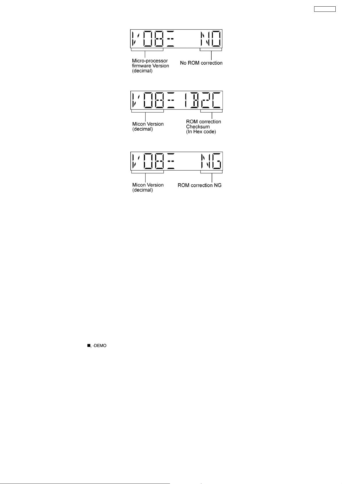
2. When EEPROM IC is detecte d and has ROM correction:
3. When EEPROM IC is detected and has ROM correction but NG:
SA-PM33EE
Note: Micro-processor firmware version refers to version No. (Eg.MS079_12) for micro-processor IC.
It is subject to change which would update accordingly.
· Rom correction checksum refers to the hex code that is display upon key buttons pressed if an EEPRO M is loaded in the unit.
(Main P.C.B)
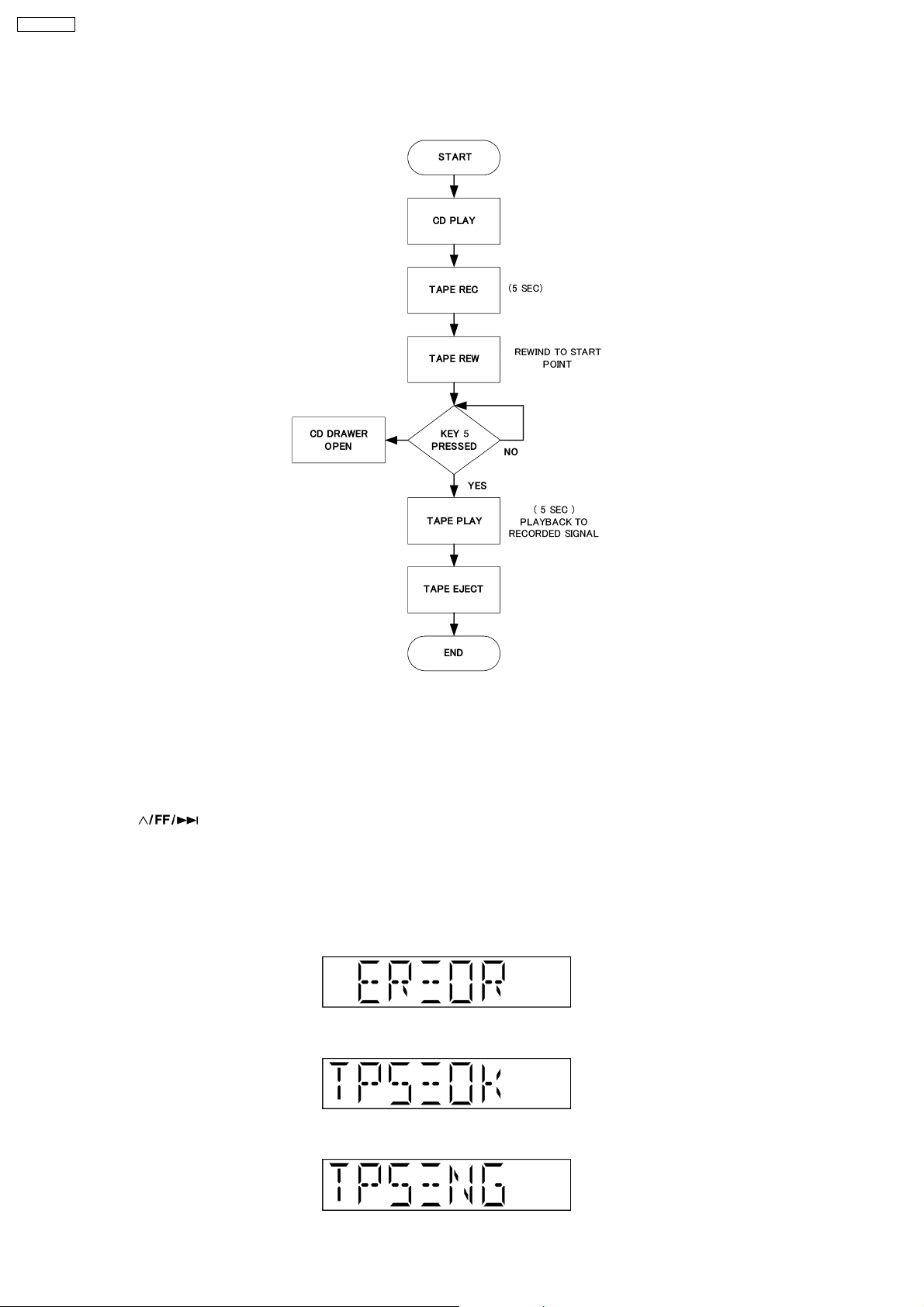
8.1.3. CD to Tape Recording Inspection
Purpose : To check the recording function from CD to Tape.
Below is the procedures for this mode.
Procedure :
Step 1: Enter into Doctor mode (Refer section 8.1 Special Mode Table)
Step 2: Insert CDT-018 (Ensure TOC is completed) to CD unit before proceeding.
Step 3: Press [4] button on remote control. Enter into CD to Tape Test mode. (During this mode, volume is set to [VOLUME 50],
Bass & Treble is set to 0dB & EQ is switch off).
Note : When in CD to Tape Recording Test mode, the following process is perform :
a) Deck will rewind to start point (point at the start of recording) & Stop.
b) Recording begins (at constant analogue recording speed) for 3 seconds & Stop.
· However, “Error” would be display if there is no tracks to access to, no tape inserted, no test CD inserted or when the tape
erasure prevention tab for FWD side is not suitable for recording.
· When in this mode, if
button is pressed the process will stops automatically.
8.1.4. Tape Recording and Playing
Purpose : To check the Tape function.
Assuming the recording to TAPE has been done in test 3, only playing TAPE is made.
Below is the procedures for this mode.
Procedure :
Step 1: Enter into Doctor mode (Refer section 8.1 Special Mode Table)
Step 2: Press [5] button on remote control. Enter into Tape recording Test mode. (During this mode, Tape function is set to
automatically, volume is set to [VOLUME 50], Bass & Treble is set to 0dB & EQ is switch off).
Step 3: FWD play is made for 3 seconds after setting the above-mentioned, TAPE is stopped 3 seconds later. Tape should open.
Note : When in CD to Tape Recording Test mode, the following process is perform :
a) If the erasure prevention tab for FWD side the tape is broken, it is judged as an error and the recording operation does not start.
b) If tape stops by detecting a tape end while recording, it becomes an error.
15
SA-PM33EE
c) If STOP key is pressed while recording or playing, the operation shall be terminated by stopping TAPE. In this case, the doctor
mode is not released.
d) DMT is output with the same timing as usual.
8.1.5. TPS Inspection
Purpose : To check the TPS.
Below is the procedures for this mode.
Procedure :
Step 1: Enter into Doctor mode (Refer section 8.1 Special Mode Table)
Step 2: Press [
· Software will start checking for existence of cassette in Deck.
· If the Deck does not contain any cassette, it shall end the test and displays the result of the test.
· The test will start by playing the Deck in forward direction for 1 sec and then FF TPS.
· If TPS signal is OK, the Deck shall be ejected. Below is information on the TPS under 3 examples.
1. If ERROR Flag is set "ERROR" shall be displayed. TPS check result shall not be shown in this case.
2. If Deck TPS check = OK
3. If Deck TPS check = NG
] button on remote control. Enter into TPS Test mode. (During this mode)
16

SA-PM33EE
8.2. Error Code Table
Self-Diagnosis Function provides information on any problems occuring for the unit and its respective components by displaying
error codes. Thesed error code such as U**, H** and F** are stored in memory and held unless it is cleared.
The error code is automatically display after entering into self-diagnostic mode.
Error Code Diagnosis Contents Description of error Automatic FL Display Remarks
H01 MODE SW abnormal For deck mechanism unit.
H02 REC INH SW
H03 HALF SW abnormal For deck mechanism unit.
F01
F02
F15 CD REST SW
abnormal
Reel pulse abnormal
TPS abnormal
Abnormal
CD traverse position intial
setting operation failsafe
counter (1000 ms) waiting
for REST SW toturn on.
Error No. shall be clear by
force or during cold start.
Press [
error.
For deck mechanism unit.
Press [
error.
Press [
error.
For deck mechanism unit.
Press [
error.
For CD unit (For Traverse).
Press [
error.
] on main unit for next
] on main unit for next
] on main unit for next
] on main unit for next
] on main unit for next
17
SA-PM33EE
Error Code Diagnosis Contents Description of error Automatic FL Display Remarks
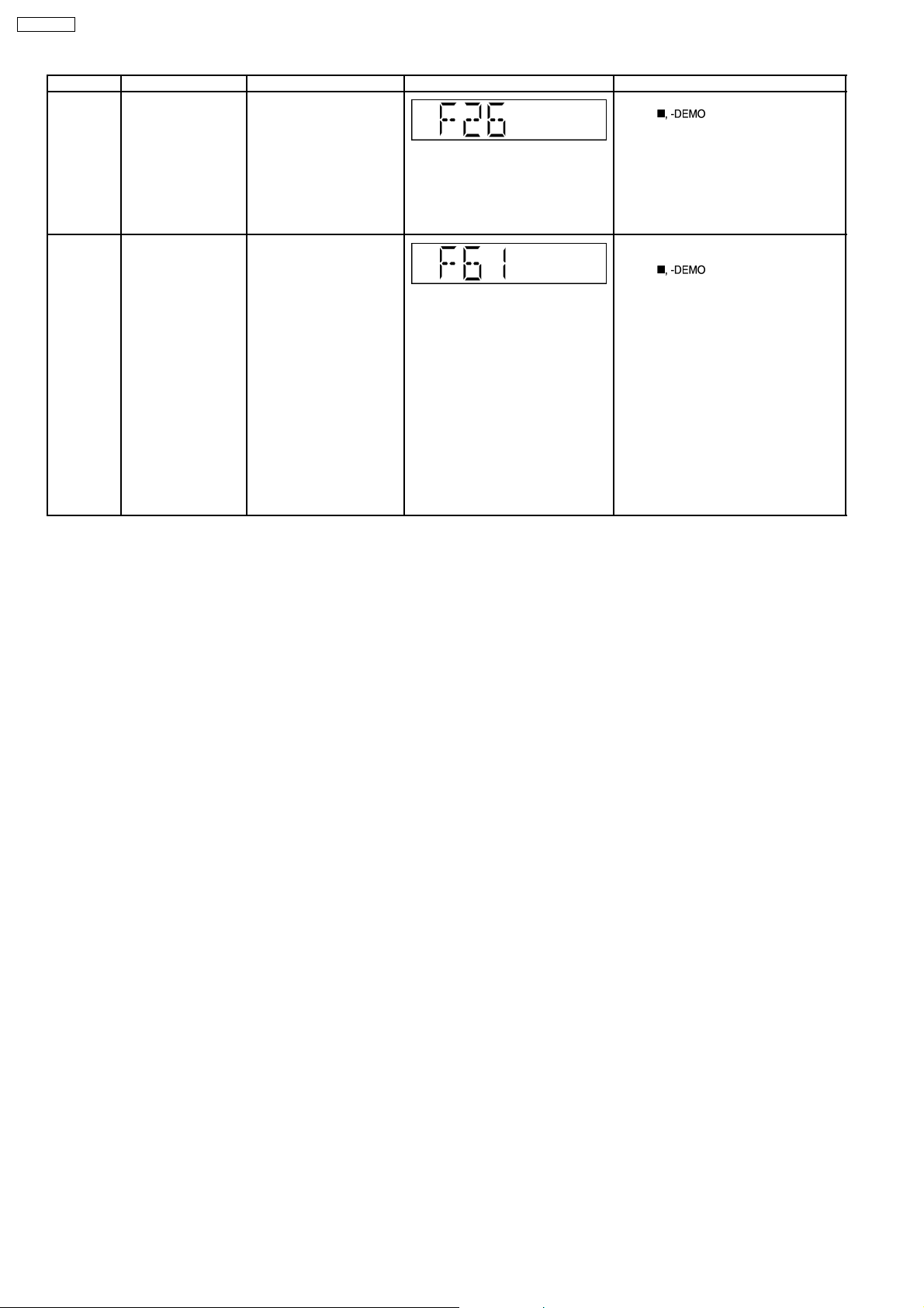
F26 Communication
between CD servo
LSI and micro-p
abnormal.
CD function DTMS
command, after system
setting, If SENSE = ´L´
cannot be detected.
Memory shall contain F26
code. After Power on, CD
function shall continue,
error display shall be "NO
DISC". Error No. shall be
clear by force or cold start.
POWER
AMP output
abnormal
During normal operation, if
DCDET becomes "L",
normal POWER OFF
process shall not be
executed, PCONT shall be
switched to "L"
immediately. "GOODBYE"
shall not be display but the
error display F61 is
displayed instead. 2
seconds after the F61
displayed, ECONO shall be
set to "L" and FL display
shall be turned off. The
error content shall be
memorized when the
abnormality occurs and can
be display in the C-mecha
self-diagnostic mode
described later.
For CD unit (For Traverse).
Press [
] on main unit for next
error.
For Power Supply Related Error
Detection.
Press [
] on main unit for next
error.
18

SA-PM33EE
9 Assembling and Disassembling
9.1. Caution
“ATTENTION SERVICER”
Some chassis components may be have sharp edges. Be careful when disassembling and servicing.
1. This section describes procedures for checking the operation of the major printed circuit boards and replacing the main
components.
2. For reassembly after operation checks or replacement, reverse the respective procedures.
Special reassembly procedures are described only when required.
3. Select items from the following index when checks or replacement are required.
Warning:
This product uses a laser diode. Refer to “Precaution of Laser Diode”.
Below is the list of disassembly sections
· Disasse mbly of Side Panel L & R
· Disasse mbly of Top Cabinet Unit
· Disasse mbly of Deck Mechanism and Tape Eject P.C.B.
· Disasse mbly of Headphone P.C.B.
· Disasse mbly of Front Panel
· Disasse mbly of Panel P.C.B.
· Disasse mbly of Rear Panel
· Disasse mbly of Tuner Pack
· Disasse mbly of Main P.C.B.
· Disasse mbly of Power P.C.B.
· Disasse mbly of Speaker Terminal P.C.B.
· Disasse mbly of Transformer P.C.B.
· Disasse mbly of CD Mechanism
· Disasse mbly of Cassette Lid
· Disasse mbly of Traverse Unit, Driving Gear, and Cam Gear (CD Mechanism Unit)
· Disasse mbly of Optical Pickup (CD Mechanism Unit)
· Disasse mbly of Traverse Gear A and Traverse Gear B (CD Mechanism Unit)
· Disasse mbly of Pinch Roller and Head Block (Deck Mechanism Unit)
· Disasse mbly of Motor, Capstan Belt A, Capstan Belt B, and Winding Belt (Deck Mechanism Unit)
· Disasse mbly of Deck Mechanism P.C.B.
· Handling of cassette tape jam
19

SA-PM33EE
9.2. Disassembly flow chart
The following chart is the procedure for disassembling the casing and inside parts for internal inspection when carrying out the
servicing.
To assemble the unit, reverse the steps shown in the chart below.
20

9.3. Main Parts Location Diagram
SA-PM33EE
21
SA-PM33EE
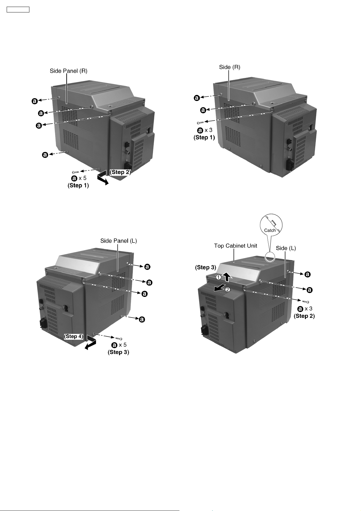
9.4. Disassembly of Side Panel L &
R
· Disasse mbly of Side Panel (R)
Step 1: Remove 5 screws.
Step 2: Remove the side panel (R) as arrow shown.
9.5. Disassembly of Top Cabinet
Unit
Step 1: Remove 3 screws.
· Disasse mbly of Side Panel (L)
Step 3: Remove 5 screws.
Step 4: Remove the side panel (L) as arrow shown.
Step 2: Remove 3 screws.
Step 3: Lift up the top cabine t unit, push backward
as arrow shown and flip top cabinet unit sideway.
(Be careful of the catch)
22
SA-PM33EE
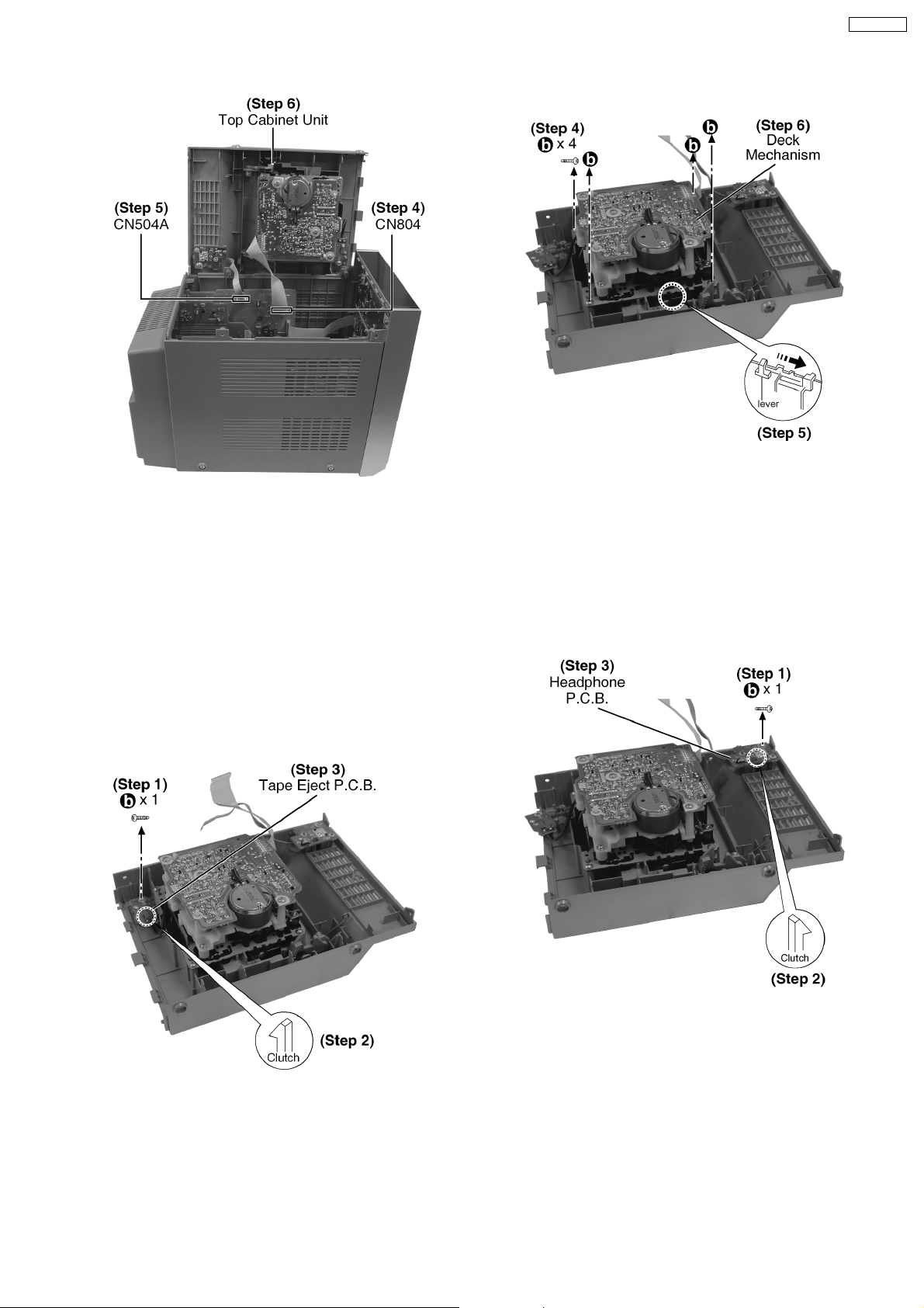
Step 4: Disconnect FFC cable (CN804).
Step 5: Detach connector (CN504A).
Step 6: Remove top cabinet unit.
9.6. Disassembly of Deck
Mechanism and Tape Eject
P.C.B.
· Follow the (Step 1) - (Step 6) of Item 9.5.
· Disasse mbly of Tape Eject P.C.B.
Step 4: Remove 4 screws.
Step 5: Push the lever as arrow shown to open the
cassette lid.
Step 6: Remove the Deck Mechanism.
9.7. Disassembly of Headphone
P.C.B.
· Follow the (Step 1) - (Step 6) of Item 9.5.
Step 1: Remove 1 screw.
Step 2: Releas e the clutch.
Step 3: Remove the Tape Eject P.C.B.
· Disasse mbly of Deck Mechanism.
Step 1: Remove 1 screw.
Step 2: Releas e the clutch.
Step 3: Remove the Headphone P.C.B.
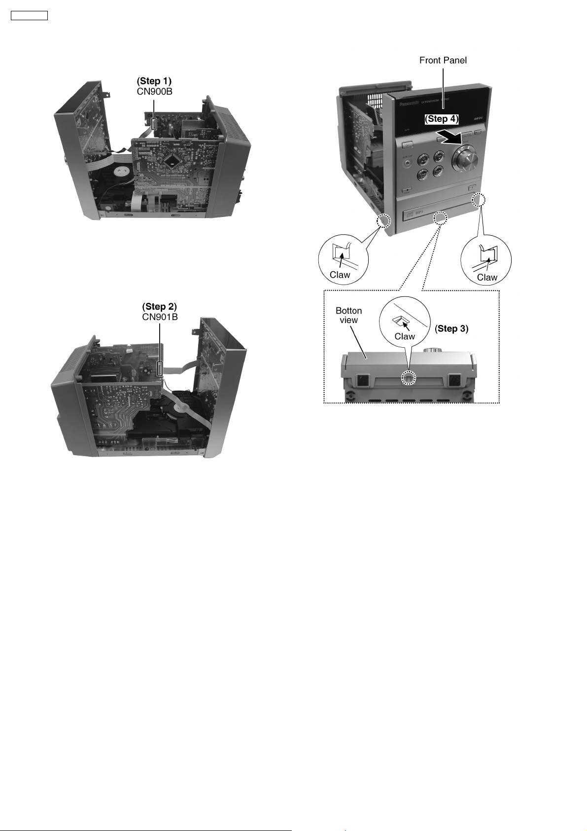
9.8. Disassembly of Front Panel
· Follow the (Step 1) - (Step 4) of Item 9.4.
· Follow the (Step 3) - (Step 6) of Item 9.5.
23
SA-PM33EE
Step 1: Detach connector (CN900B).
Step 2: Disconnect FFC cable (CN901B).
Step 3: Releas e 3 claws.
Step 4: Remove the Front Panel as arrow shown.
9.9. Disassembly of Panel P.C.B.
· Follow the (Step 1) - (Step 4) of Item 9.4.
· Follow the (Step 3) - (Step 6) of Item 9.5.
· Follow the (Step 1) - (Step 4) of Item 9.8.
24

Step 1: Detach the connector CN401A and remove
the tuner pack as arrow shown.
SA-PM33EE
Step 1: Remove 10 screws.
Step 2: Remove the Volume Knob.
Step 3: Releas e 2 catches.
Step 4: Remove the Panel P.C.B.
9.10. Disassembly of Rear Panel
· Follow the (Step 1) - (Step 4) of Item 9.4.
· Follow the (Step 3) - (Step 6) of Item 9.5.
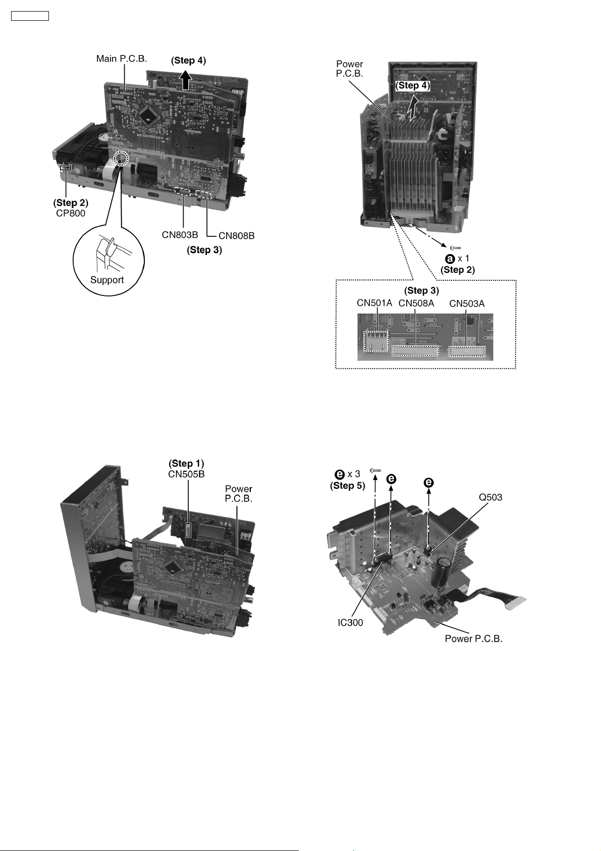
9.12. Disassembly of Main P.C.B.
· Follow the (Step 1) - (Step 4) of Item 9.4.
· Follow the (Step 1) - (Step 6) of Item 9.5.
· Follow the (Step 1) - (step 4) of Item 9.8.
· Follow the (Step 1) - (step 2) of Item 9.10.
Step 1: Detach the FFC CN801.
Step 1: Remove 5 screws.
Step 2: Remove the Rear Panel as arrow shown.
9.11. Disassembly of Tuner Pack
· Follow the (Step 1) - (Step 4) of Item 9.4.
· Follow the (Step 3) - (Step 6) of Item 9.5.
· Follow the (Step 1) - (Step 2) of Item 9.10.
25
SA-PM33EE
Step 2: Detach connector CP800 .
Step 3: Detach connector CN803 B and CN808B.
Step 4: Remove the Main P.C.B. as arrow shown.
9.13. Disassembly of Power P.C.B.
· Follow the (Step 1) - (Step 4) of Item 9.4.
· Follow the (Step 4) - (Step 6) of Item 9.5.
· Follow the (Step 1) - (Step 2) of Item 9.10.
Step 2: Remove 1 screw.
Step 3: Detach the connector CN501A, CN508A
and CN503A.
Step 4: Remove the Power P.C.B. as arrow shown.
· Replacement of Power Amplifier IC
Step 1: Detach the connector CN505B.
Step 5: Remove 3 screws.
26

Step 6: Unsold er the terminal of Power Amp IC
(IC300) and replace the component.
Step 7: Unsold er the terminal of Transistor (Q503)
and replace the component.
SA-PM33EE
9.15. Disassembly of Transformer
P.C.B.
· Follow the (Step 1) - (Step 4) of Item 9.4.
· Follow the (Step 4) - (Step 6) of Item 9.5.
· Follow the (Step 1) - (Step 2) of Item 9.10.
· Follow the (Step 1) - (Step 4) of Item 9.13.
9.14. Disassembly of Speaker
Terminal P.C.B.
· Follow the (Step 1) - (Step 4) of Item 9.4.
· Follow the (Step 4) - (Step 6) of Item 9.5.
· Follow the (Step 1) - (step 2) of Item 9.10.
· Follow the (Step 3) of Item 9.12.
· Follow the (Step 1) - (step 4) of Item 9.13.
Step 1: Detach the connector CN900B.
Step 2: Remove 4 screws.
Step 3: Remove the Transformer P.C.B. as arrow
shown.
9.16. Disassembly of CD
Mechanism
· Follow the (Step 1) - (Step 4) of Item 9.4.
· Follow the (Step 4) - (step 6) of Item 9.5.
· Follow the (Step 1) - (step 4) of Item 9.8.
· Follow the (Step 1) - (step 2) of Item 9.10.
· Follow the (Step 1) - (step 4) of Item 9.12.
Step 1: Remove 1 screw.
Step 2: Releas e the clutch.
Step 3: Remove the Speaker Terminal P.C.B. as
arrow shown.
27

SA-PM33EE
Step 1: Remove 4 screws.
Step 2: Remove the Main P.C.B. support.
Step 3: Remove CD Mechanism as arrow shown.
9.17. Disassembly of Cassette Lid
· Follow the (Step 1) - (Step 2) of Item 9.4.
· Follow the (Step 3) - (Step 6) of Item 9.5.
· Follow the (Step 1) - (step 4) of Item 9.6.
Step 2: Remove the Cassette Open Spring as
arrow shown in order.
Step 1: Using screwdriver to remove Damper gear
as arrow shown.
Step 3: Pull the sides Cassette holders to the
direction of the arrows shown.
28

Step 4: Remove the Cassette Lid as arrows shown.
9.18. Disassembly of Traverse Unit,
Driving Gear, and Cam Gear
(CD Mechanism Unit)
SA-PM33EE
9.18.1. Disassembly of the Traverse Unit
· Follow the (Step 1) - (Step 4) of Item 9.4.
· Follow the (Step 4) - (Step 6) of Item 9.5.
· Follow the (Step 1) - (Step 4) of Item 9.8.
· Follow the (Step 1) - (Step 2) of Item 9.10 .
· Follow the (Step 1) - (Step 4) of Item 9.12.
· Follow the (Step 1) - (Step 3) of Item 9.16.
· Disasse mbly of gears drive
29
 Loading...