

Panasonic SAPM-27-E Service manual
file:///C|/Documents%20and%20Settings/Administrator/Plocha/PANASONIC%20SA-PM27E/s0000000000.htm
Service Manual
TOP NEXT
Order No. MD0206158C2
CD Stereo System
● SA-PM27E
SA-PM27EB
SA-PM27EG
Colour
(K) ... Black Type
Specification
Amplifier Section
RMS Power output
10% Total harmonic distortion
100 Hz, both channels driven (Low channel)
30 W per channel (6Ω)
1 kHz, both channels driven (High channel)
30 W per channel (6Ω)
Total Bi-Amp power 60 W per channel
Input sensitivity
AUX 250 mV
Input impedance
AUX
11.8 kΩ
FM Tuner Section
Frequency range 87.50-108.00 MHz (50 kHz steps)
Sensitivity 1.8•V (IHF)
S/N 26 dB 1.5•V
Antenna terminal(s)
75Ω (unbalanced)
AM Tuner Section
Frequency range 522-1629 kHz (9 kHz steps)
Sensitivity
S/N 20 dB (at 999 kHz) 560•V/m
file:///C|/Documents%20and%20Settings/Administrator/Plocha/PANASONIC%20SA-PM27E/s0000000000.htm (1 of 3) [14.6.2003 18:23:08]
file:///C|/Documents%20and%20Settings/Administrator/Plocha/PANASONIC%20SA-PM27E/s0000000000.htm
Cassette Deck Section
Track system 4 track, 2 channel
Heads
Record/playback Solid permalloy head
Erasure Double gap ferrite head
Motor DC servo motor
Recording system AC bias 100 kHz
Erasing system AC erase 100 kHz
Tape speed 4.8 cm/s
Overall frequency response (+3 dB, -6 dB at Deck Out)
Normal (type I) 35 Hz - 14 kHz
S/N 50 dB (A weighted)
Wow and flutter 0.18% (WRMS)
Fast forward and rewind times Approx. 120 seconds with C-60 cassette tape
CD Section
Sampling frequency 44.1 kHz
Decoding 16 bit linear
Pickup
Beam source/ Wavelength Semiconductor laser/ 780 nm
Number of channels Stereo
Frequency response 20 Hz - 20 kHz (+1, -2 dB)
Wow and flutter Below measurable limit
Digital filter 8 fs
D/A converter MASH (1 bit DAC)
General
Power supply AC 230 V, 50 Hz
Power consumption 110 W
Dimensions (W x H x D) 179 x 241 x 375 mm
Mass 5.6 kg
Power consumption in standby mode Approx. 0.7 W
System: SC-PM27(E) Music Center: SA-PM27(E)
Speaker: SB-PM27(P)
System: SC-PM27(EB) Music Center: SA-PM27(EB)
Speaker: SB-PM27(P)
System: SC-PM27(EG) Music Center: SA-PM27(EG)
Speaker: SB-PM27(EG)
Notes:
1. Specifications are subject to change without notice.
Mass and dimensions are approximate.
2. Total harmonic distortion is measured by the digital spectrum analyzer.
© 2002 Matsushita Electronics (S) Pte. Ltd. All rights reserved. Unauthorized copying and distribution is a violation of law.
file:///C|/Documents%20and%20Settings/Administrator/Plocha/PANASONIC%20SA-PM27E/s0000000000.htm (2 of 3) [14.6.2003 18:23:08]

file:///C|/Documents%20and%20Settings/Administrator/Plocha/PANASONIC%20SA-PM27E/s0100000000x.htm
1 Before Repair and Adjustment
TOP PREVIOUS NEXT
Disconnect AC power, discharge Power Supply Capacitors C506, C507, C508, C576, C577, C587,
C588, C615 through a 10 Ω, 5 W resistor to ground. DO NOT SHORT-CIRCUIT DIRECTLY (with a
screw driver blade, for instance), as this may destroy solid statedevices.
After repairs are completed, restore power gradually using a variac, to avoid over current.
Current consumption at AC 230 V, 50 Hz in NO SIGNAL mode should be ~300 mA.
TOP PREVIOUS NEXT
file:///C|/Documents%20and%20Settings/Administrator/Plocha/PANASONIC%20SA-PM27E/s0100000000x.htm [14.6.2003 18:24:11]

file:///C|/Documents%20and%20Settings/Administrator/Plocha/PANASONIC%20SA-PM27E/s0200000000x.htm
2 Protection Circuitry
TOP PREVIOUS NEXT
The protection circuitry may have operated if either of the following conditions are noticed:
● No sound is heard when the power is turned on.
● Stops during a performance.
The function of this circuitry is to prevent circuitry damage if, for example, the positive and negative
speaker connection wires are “shorted”, or if speaker systems with an impedance less than the indicated
rated impedance ofthe amplifier are used.
If this occurs, follow the procedure outlines below:
1. Turn off the power.
2. Determine the cause of the problem and correct it.
3. Turn on the power once again after one minute.
Note:
When the protection circuitry functions, the unit will not operate unless the power is first turned off and
then on again.
TOP PREVIOUS NEXT
file:///C|/Documents%20and%20Settings/Administrator/Plocha/PANASONIC%20SA-PM27E/s0200000000x.htm [14.6.2003 18:24:38]

file:///C|/Documents%20and%20Settings/Administrator/Plocha/PANASONIC%20SA-PM27E/s0300000000x.htm
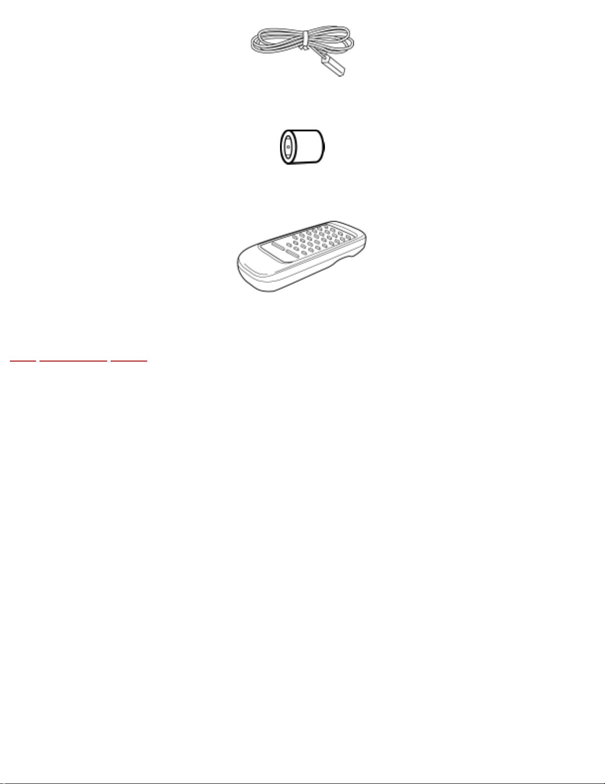
3 Accessories
TOP PREVIOUS NEXT
AC Mains lead (E/EG).....1 pc
AC Mains lead (EB).....1 pc
AM Loop Antenna.....1 pc
FM Indoor Antenna.....1 pc
file:///C|/Documents%20and%20Settings/Administrator/Plocha/PANASONIC%20SA-PM27E/s0300000000x.htm (1 of 2) [14.6.2003 18:25:03]
file:///C|/Documents%20and%20Settings/Administrator/Plocha/PANASONIC%20SA-PM27E/s0300000000x.htm
Antenna Plug Adaptor.....1 pc (EB only)
Remote Control Transmitter.....1 pc
TOP PREVIOUS NEXT
file:///C|/Documents%20and%20Settings/Administrator/Plocha/PANASONIC%20SA-PM27E/s0300000000x.htm (2 of 2) [14.6.2003 18:25:03]
file:///C|/Documents%20and%20Settings/Administrator/Plocha/PANASONIC%20SA-PM27E/s0400000000x.htm
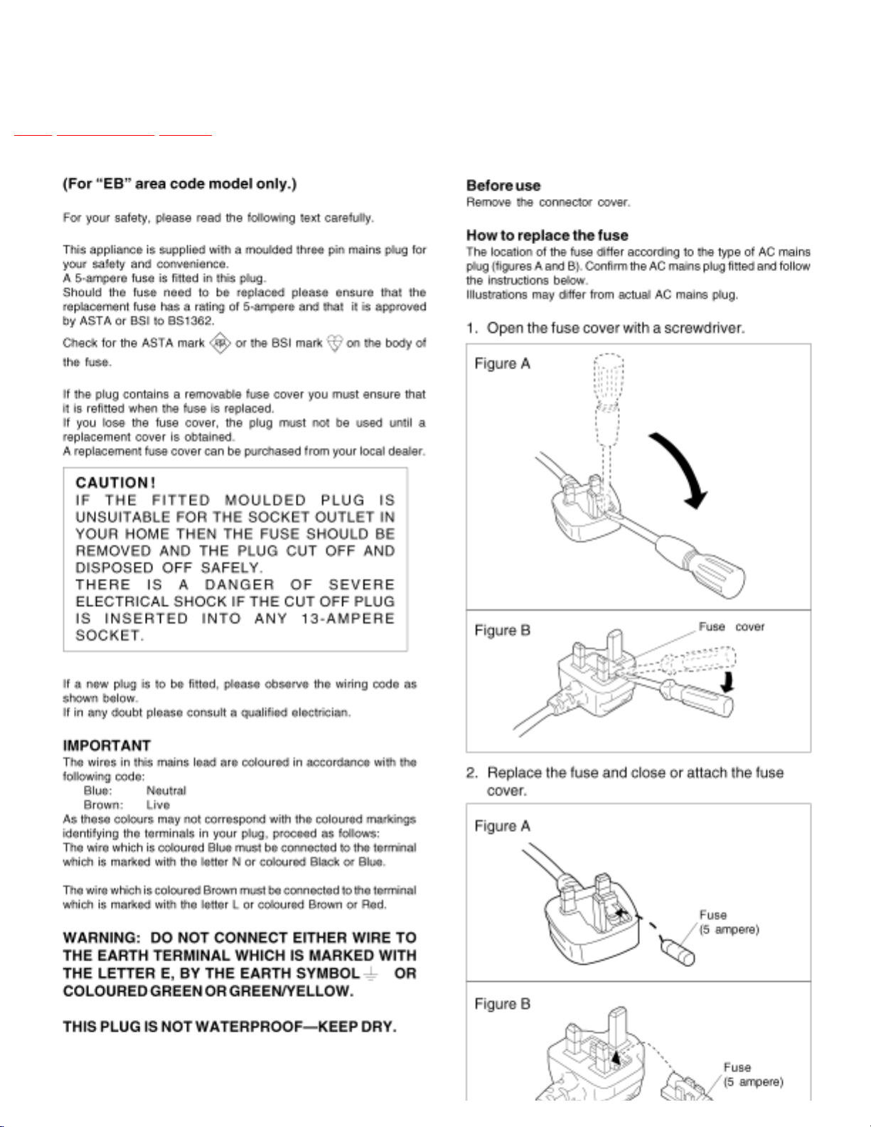
4 Caution for AC Mains Lead
TOP PREVIOUS NEXT
file:///C|/Documents%20and%20Settings/Administrator/Plocha/PANASONIC%20SA-PM27E/s0400000000x.htm (1 of 2) [14.6.2003 18:25:35]

file:///C|/Documents%20and%20Settings/Administrator/Plocha/PANASONIC%20SA-PM27E/s0500000000x.htm
5 Self-Diagnostic Display Function
TOP PREVIOUS NEXT
This unit is equipped with a self-diagnostic display function, which will be useful during servicing and
maintenance.
● Refer to the next page for display symbols, symptoms, etc.
5.1 Preparations
5.2 Setting of the Self-Diagnostic Mode
5.3 Restoring Normal Display
5.4 Clearing Self-Diagnostic Memory
5.5 Displaying Self-Diagnostic Results
TOP PREVIOUS NEXT
file:///C|/Documents%20and%20Settings/Administrator/Plocha/PANASONIC%20SA-PM27E/s0500000000x.htm [14.6.2003 18:25:57]

file:///C|/Documents%20and%20Settings/Administrator/Plocha/PANASONIC%20SA-PM27E/s0501000000.htm
5.1 Preparations
TOP PREVIOUS NEXT
1. A Cr02-positioned blank cassette tape with an erase prevention niche on either Side A or B.
2. A normal-positioned music tape with erase prevention niches on both Sides A and B. Both tapes
are halfway forwarded in advance.
3. The remote controller that comes with this unit.
TOP PREVIOUS NEXT
file:///C|/Documents%20and%20Settings/Administrator/Plocha/PANASONIC%20SA-PM27E/s0501000000.htm [14.6.2003 18:26:20]
file:///C|/Documents%20and%20Settings/Administrator/Plocha/PANASONIC%20SA-PM27E/s0502000000.htm
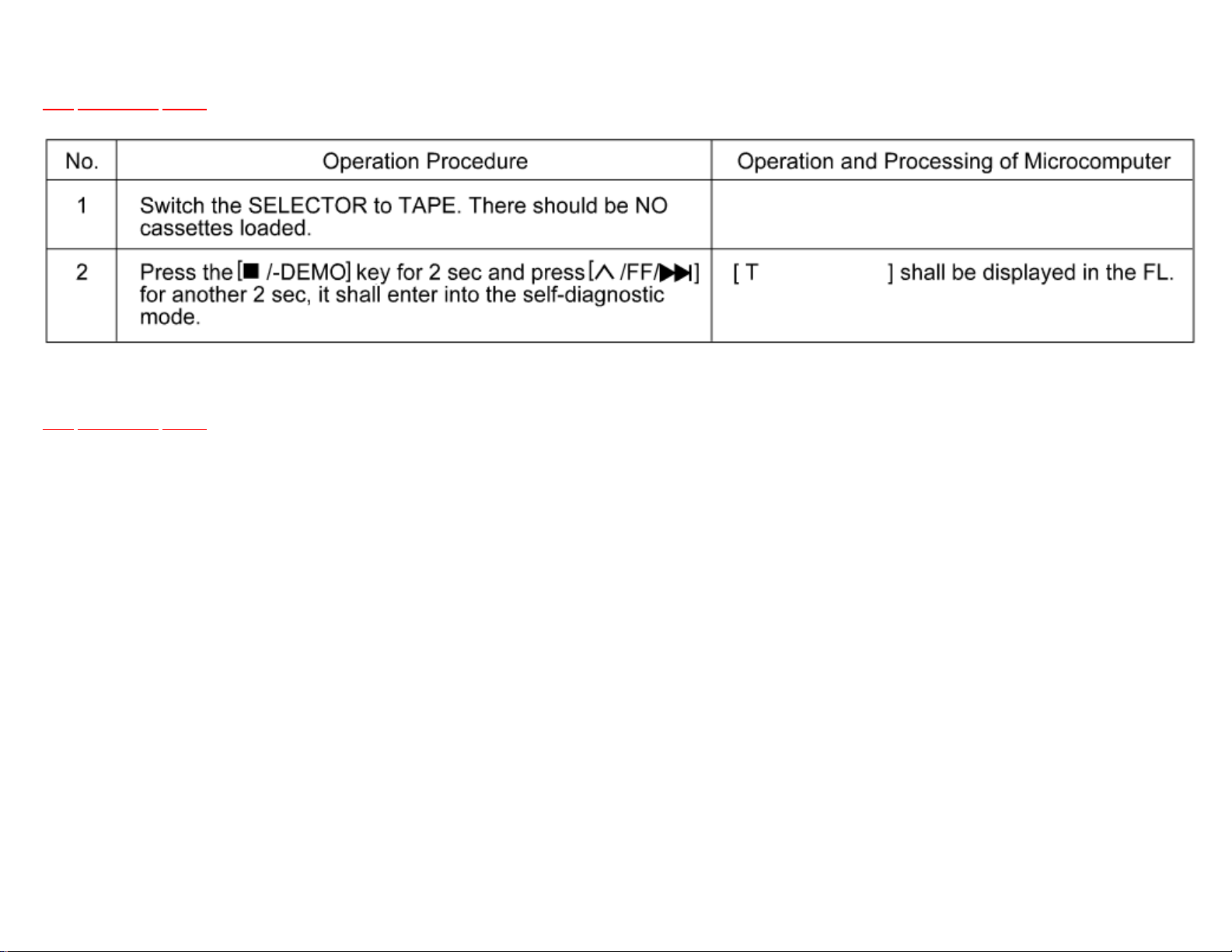
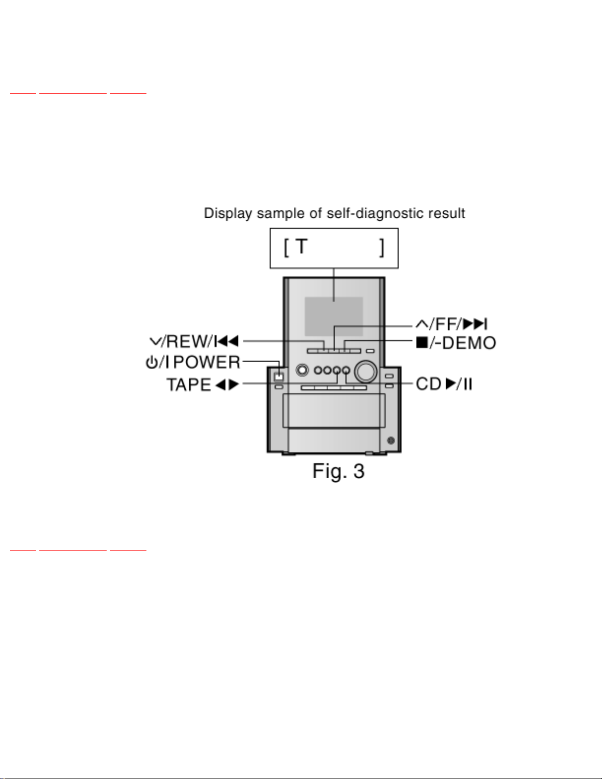
5.2 Setting of the Self-Diagnostic Mode
TOP PREVIOUS NEXT
TOP PREVIOUS NEXT
file:///C|/Documents%20and%20Settings/Administrator/Plocha/PANASONIC%20SA-PM27E/s0502000000.htm [14.6.2003 18:26:45]
file:///C|/Documents%20and%20Settings/Administrator/Plocha/PANASONIC%20SA-PM27E/s0503000000.htm
5.3 Restoring Normal Display
TOP PREVIOUS NEXT
● From the F76 display, the normal display does not appear till an error is recovered.
● For displays other than F76, press “POWER” button to turn off the power, and then turn on the
power.
TOP PREVIOUS NEXT
file:///C|/Documents%20and%20Settings/Administrator/Plocha/PANASONIC%20SA-PM27E/s0503000000.htm [14.6.2003 18:27:07]

file:///C|/Documents%20and%20Settings/Administrator/Plocha/PANASONIC%20SA-PM27E/s0504000000.htm
5.4 Clearing Self-Diagnostic Memory
TOP PREVIOUS NEXT
<CD Section> (F15, F17, F22, F26, F27, F28, F29)
1. Enter a self-diagnostic mode.
2. Press "
/-DEMO" button. A symbol of self-diagnostic is indicated on the display if an error is found. If
several errors are found, a respective indication is displayed when"
/-DEMO" button is pressing repeatedly. (e.g. H01 → CD F15 → F01)
If no error is found, only "TEST" indication is displayed and remains unchange even if "
/-DEMO" button is pressed.
TOP PREVIOUS NEXT
file:///C|/Documents%20and%20Settings/Administrator/Plocha/PANASONIC%20SA-PM27E/s0504000000.htm [14.6.2003 18:27:45]

file:///C|/Documents%20and%20Settings/Administrator/Plocha/PANASONIC%20SA-PM27E/s0505000000.htm
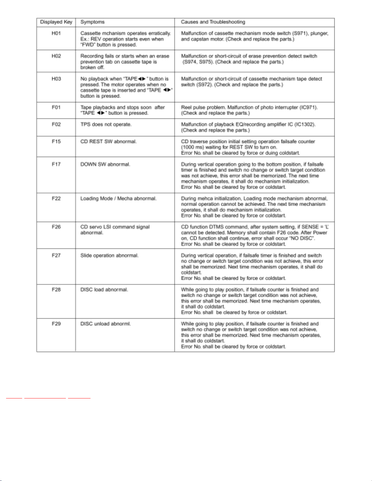
5.5 Displaying Self-Diagnostic Results
TOP PREVIOUS NEXT
<Cassette Deck Section> (H01, H02, H03, F01, F02)
1. Enter the self-diagnostic mode, following the instructions described in [5.2. Entering SelfDiagnostic Mode].
2. Insert a normal-positioned music tape with erase prevention niches on both Sides A and B. Press
[TAPE
] button to activate the TPS operation so that the tape automatically stopsat an interval
between music selections.
3. Press [ /CLEAR] and [TAPE
] buttons together on the remote controller. (Recording does not start.)
4. Then, insert a Cr02-positioned blank cassette tape with an erase prevention niche of Side A or B
set to the left side.
5. Press [
/FF/
] button. The tape will be forwarded and automatically stop after two seconds.
6. Remove the cassette tape, and set the other side.
7. Press [
/REW/
] button. The tape will be rewound and automatically stops after two seconds.
8. Press [
/-DEMO] button on the unit.
file:///C|/Documents%20and%20Settings/Administrator/Plocha/PANASONIC%20SA-PM27E/s0505000000.htm (1 of 3) [14.6.2003 18:28:08]

file:///C|/Documents%20and%20Settings/Administrator/Plocha/PANASONIC%20SA-PM27E/s0505000000.htm
If an error is found, a self-diagnostic key appears on the display.
If several errors are found, the display shows these keys when [
/-DEMO] button is pressed repeatedly. (Ex.: H01 - H02 - F01 - H01)
If no error is found, only the message, “CD TEST” appears on the display.
(*1) TPS operation (music search) detects the blank sections between music selections. Therefore, do not
use tapes with the following conditions:
● A blank section that lasts only 4 seconds or less.
● No blank sections (recording through microphones, etc.).
● Music selections that have extremely low pitches or prolonged silent sections (such as classical
music).
● and/or Music recorded with fade in/out effect.
file:///C|/Documents%20and%20Settings/Administrator/Plocha/PANASONIC%20SA-PM27E/s0505000000.htm (2 of 3) [14.6.2003 18:28:08]
file:///C|/Documents%20and%20Settings/Administrator/Plocha/PANASONIC%20SA-PM27E/s0505000000.htm
TOP PREVIOUS NEXT
file:///C|/Documents%20and%20Settings/Administrator/Plocha/PANASONIC%20SA-PM27E/s0505000000.htm (3 of 3) [14.6.2003 18:28:08]

file:///C|/Documents%20and%20Settings/Administrator/Plocha/PANASONIC%20SA-PM27E/s0600000000x.htm
6 Handling Precautions For Traverse
Deck
TOP PREVIOUS NEXT
The laser diode in the traverse deck (optical pickup) may break down due to potential difference caused
by static electricity of clothes or human body. So, be careful of electrostatic breakdown during repair of
the traverse deck (optical pickup).
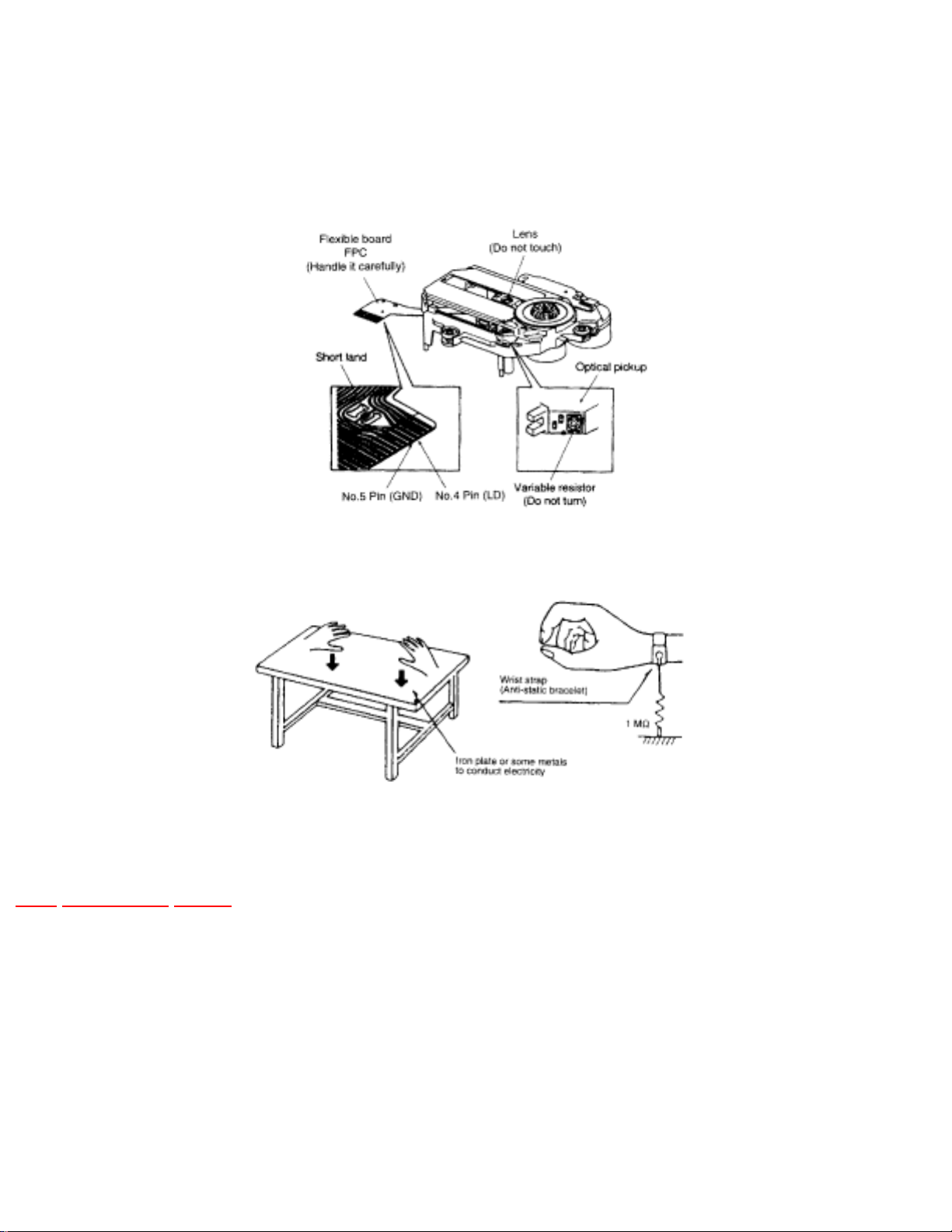
● Handling of traverse deck (optical pickup)
1. Do not subject the traverse deck (optical pickup) to static electricity as it is extremely
sensitive to electrical shock.
2. To prevent the breakdown of the laser diode, an antistatic shorting pin is inserted into the
flexible board (FFC board).
3. Take care not to apply excessive stress to the flexible board (FFC board). When removing
or connecting the short pin, finish the job in as short time as possible.
4. Do not turn the variable resistor (laser power adjustment). It has already been adjusted.
● Grounding for electrostatic breakdown prevention
1. Human body grounding
Use the anti-static wrist strap to discharge the static electricity from your body.
2. Work table grounding.
Put a conductive material (sheet) or steel sheet on the area where the traverse deck (optical
pickup) is place, and ground the sheet.
Caution:
The static electricity of your clothes will not be grounded through the wrist strap. So, take care not to let
your clothes touch the traverse deck (optical pickup).
file:///C|/Documents%20and%20Settings/Administrator/Plocha/PANASONIC%20SA-PM27E/s0600000000x.htm (1 of 2) [14.6.2003 18:28:31]
file:///C|/Documents%20and%20Settings/Administrator/Plocha/PANASONIC%20SA-PM27E/s0600000000x.htm
Cross-Ref] 20442: Body: Caution:Caution when replacing the
Traverse Deck
The traverse deck has a short point shorted with solder to protect the laser diode against electrostatics
breakdown. Be sure to remove the solder from the short point before making connections.
TOP PREVIOUS NEXT
file:///C|/Documents%20and%20Settings/Administrator/Plocha/PANASONIC%20SA-PM27E/s0600000000x.htm (2 of 2) [14.6.2003 18:28:31]

file:///C|/Documents%20and%20Settings/Administrator/Plocha/PANASONIC%20SA-PM27E/s0700000000x.htm
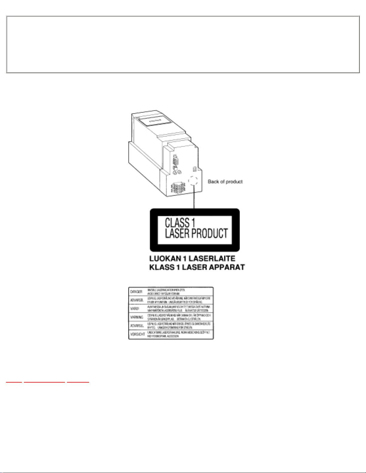
7 Precaution of Laser Diode
TOP PREVIOUS NEXT
CAUTION:
This product utilizes a laser diode with the unit truned “ON”, invisible laser radiation is emitted from the
pick up lens.
Wavelength : 780 nm
Maximum output radiation power from pick up : 100•W/VDE
Laserradiation from pick up unit is safety level, but be sure the followings:
1. Do not disassemble the optical pick up unit, since radiation from exposed laser diode is
dangerous.
2. Do not adjust the variable resistor on the pick up unit. It was already adjusted.
3. Do not look at the focus lens using optical instruments.
4. Recommend not to look at pick up lens for a long time.
ACHTUNG:
Dieses Produkt enthält eine Laserdiode. Im enigeschalteten Zustand wird unsichtbare Laserstrahlung von
der Lasereinheit abgestrahlt.
Wellenlänge : 780nm
Maximale Strahlungsleistung der Lasereinheit : 100•W/VDE
DieStrahlung an der Lasereinheit ist ungefährlich, wenn folgende Punkte beachtet werden:
1. Die Lasereinheit nicht zerlegen, da die Strahlung an der freigelegten Laserdiode gefährlich ist.
2. Den werkseitig justierten Einstellregler der Lasereinhit nicht verstellen.
3. Nicht mit optischen Instrumenten in die Fokussierlinse blicken.
4. Nicht über längere Zeit in die Fokussierlinse blicken.
ADVARSEL: I dette a apparat anvendes laser.
file:///C|/Documents%20and%20Settings/Administrator/Plocha/PANASONIC%20SA-PM27E/s0700000000x.htm (1 of 2) [14.6.2003 18:28:52]
file:///C|/Documents%20and%20Settings/Administrator/Plocha/PANASONIC%20SA-PM27E/s0700000000x.htm
CAUTION!
THIS PRODUCT UTILIZES A LASER.
USE OF CONTROLS OR ADJUSTMENTS OR PERFORMANCE OF PROCEDURES OTHER THAN THOSE SPECIFIED HEREIN MAY
RESULT IN HAZARDOUS RADIATION EXPOSURE.
Use of Caution Labels
TOP PREVIOUS NEXT
file:///C|/Documents%20and%20Settings/Administrator/Plocha/PANASONIC%20SA-PM27E/s0700000000x.htm (2 of 2) [14.6.2003 18:28:52]

file:///C|/Documents%20and%20Settings/Administrator/Plocha/PANASONIC%20SA-PM27E/s0800000000o.htm
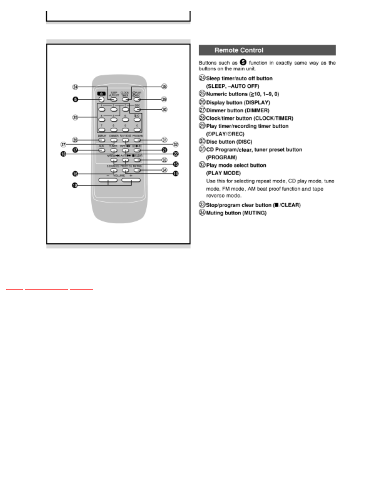
8 Front Panel Controls
TOP PREVIOUS NEXT
file:///C|/Documents%20and%20Settings/Administrator/Plocha/PANASONIC%20SA-PM27E/s0800000000o.htm (1 of 2) [14.6.2003 18:29:16]
file:///C|/Documents%20and%20Settings/Administrator/Plocha/PANASONIC%20SA-PM27E/s0800000000o.htm
TOP PREVIOUS NEXT
file:///C|/Documents%20and%20Settings/Administrator/Plocha/PANASONIC%20SA-PM27E/s0800000000o.htm (2 of 2) [14.6.2003 18:29:16]

file:///C|/Documents%20and%20Settings/Administrator/Plocha/PANASONIC%20SA-PM27E/s0900000000e.htm
9 Disassembly and Main Component
Replacement Procedures.
TOP PREVIOUS NEXT
“ATTENTION SERVICER”
Some chassis components maybe have sharp edges. Be careful when diassembling and servicing.
1. This section describes procedures for checking the operation of the major printed circuit boards
and replacing the main components.
2. For reassembly after operation checks or replacement, reverse the respective procedures.
Special reassembly procedures are described only when required.
3. Select items from the following index when checks or replacement are required.
Content
● Disassembly Procedure for each major P.C.B.
● Disassembly of CD Loading Unit
● Disassembly of CD Loading Section
● Disassembly of Traverse Mechanism
● Main Component Replacement Procedures
1. Cross-Ref] 24956: Body: Checking for the Panel P.C.B.Procedure of replacing Cassette
Holder
2. Procedure of replacing Pinch Roller and Head Block (Cassette Mechanism Unit)
3. Procedure of replacing Motor, Capstan Belt A, Capstan Belt B and Winding Belt (Cassette
Mechanism Unit)
4. Procedure of replacing Parts on Mechanism P.C.B
file:///C|/Documents%20and%20Settings/Administrator/Plocha/PANASONIC%20SA-PM27E/s0900000000e.htm (1 of 3) [14.6.2003 18:29:41]

file:///C|/Documents%20and%20Settings/Administrator/Plocha/PANASONIC%20SA-PM27E/s0900000000e.htm
5. Replacement of CD Traverse Deck
6. Replacement of Optical Pickup Unit (CD Mechanism)
7. Replacement of a Traverse Gear A and a Traverse Gear B
8. Replacement of Disk Tray
9. Replacement of the Traverse Mechanism
10. Replacement of CD Loading Unit
● Assembly of CD Loading Unit
● Handling of Cassette Tape jam
Warning:
This product uses a laser diode. Refer to “Precaution of Laser Diode”.
ACHTUNG:
Die Lasereinheit nicht zerlegen.
Die Lasereinheit darf nur gegen eine vom Hertsteller spezifizierte Einheit ausgetauscht werden.
9.1 Disassembly Procedure for each major P.C.B.
9.2 Procedure for Replacing Cassette Holder
9.3 Procedure for Replacing Pinch Roller and Head Block (Cassette Mechanism Unit)
9.4 Procedure for Replacing Motor, Capstan Belt A, Capstan Belt B, and Winding Belt (Cassette
Mechanism Unit)
9.5 Procedure for Replacing Parts on Mechanism PCB
9.6 Replacement of CD traverse deck
file:///C|/Documents%20and%20Settings/Administrator/Plocha/PANASONIC%20SA-PM27E/s0900000000e.htm (2 of 3) [14.6.2003 18:29:41]

file:///C|/Documents%20and%20Settings/Administrator/Plocha/PANASONIC%20SA-PM27E/s0900000000e.htm
9.7 Replacement of optical pickup unit (CD mechanism)
9.8 Replacement of a traverse gear A and a traverse gear B
9.9 Disassembly of CD loading unit
9.9.1 Regarding a jig "gear"
9.10 Replacement of disk tray
9.11 Replacement of the traverse mechanism
9.12 Disassembly of CD loading section
9.13 Assembly of CD loading unit
9.13.1 Notes on fixing of CD loading section
9.14 Disassembly of traverse mechanism
9.15 Handling of cassette tape jam
TOP PREVIOUS NEXT
file:///C|/Documents%20and%20Settings/Administrator/Plocha/PANASONIC%20SA-PM27E/s0900000000e.htm (3 of 3) [14.6.2003 18:29:41]

file:///C|/Documents%20and%20Settings/Administrator/Plocha/PANASONIC%20SA-PM27E/s0901000000.htm
9.1 Disassembly Procedure for each
major P.C.B.
TOP PREVIOUS NEXT
Step 1 & 2 Remove all the screws.
file:///C|/Documents%20and%20Settings/Administrator/Plocha/PANASONIC%20SA-PM27E/s0901000000.htm (1 of 9) [14.6.2003 18:30:10]
file:///C|/Documents%20and%20Settings/Administrator/Plocha/PANASONIC%20SA-PM27E/s0901000000.htm
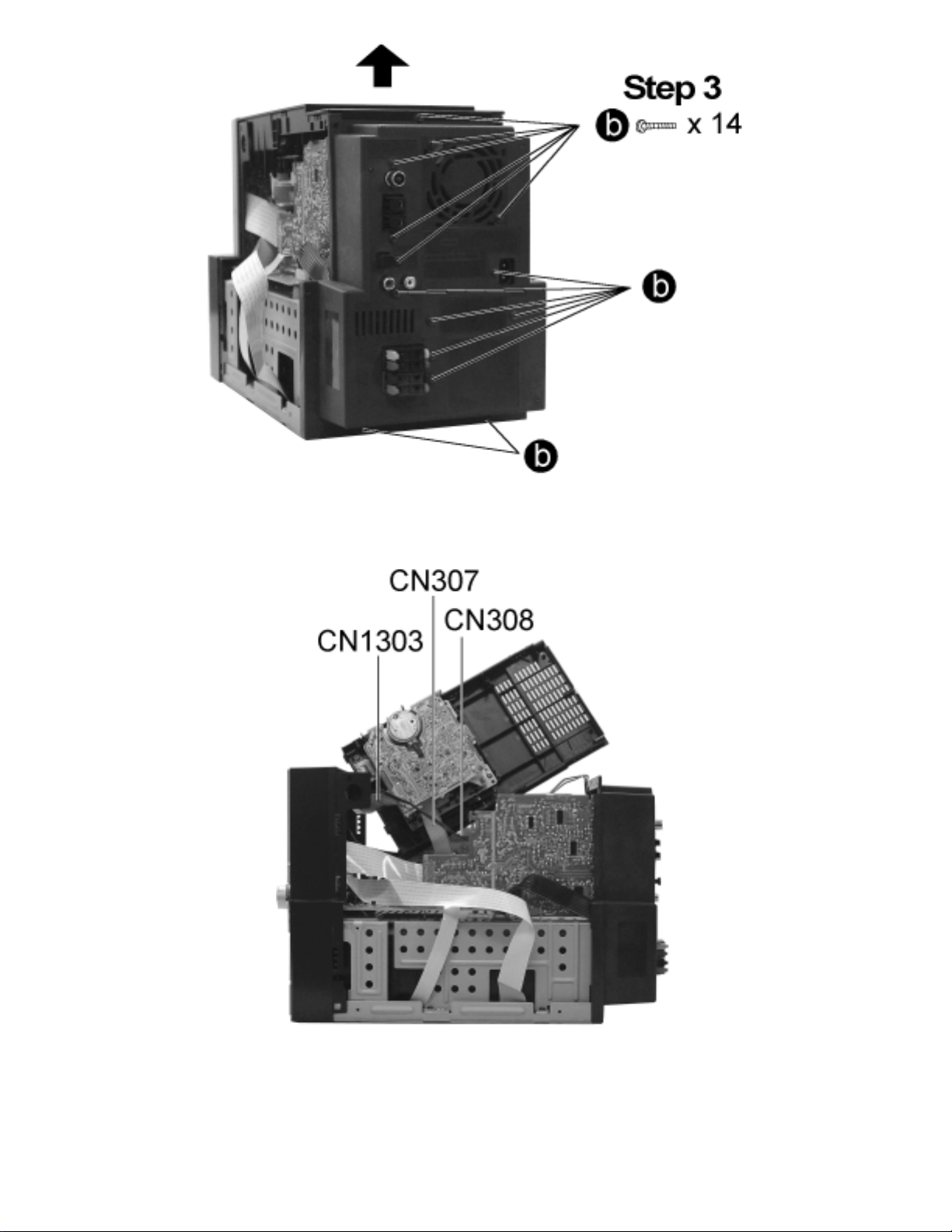
Step 3 Remove all the screws and pull up the cassette lid as the arrow shown.
Step 4 Release the connectors CN307, CN308 and CN1303. Remove the cassette lid.
file:///C|/Documents%20and%20Settings/Administrator/Plocha/PANASONIC%20SA-PM27E/s0901000000.htm (2 of 9) [14.6.2003 18:30:10]
file:///C|/Documents%20and%20Settings/Administrator/Plocha/PANASONIC%20SA-PM27E/s0901000000.htm
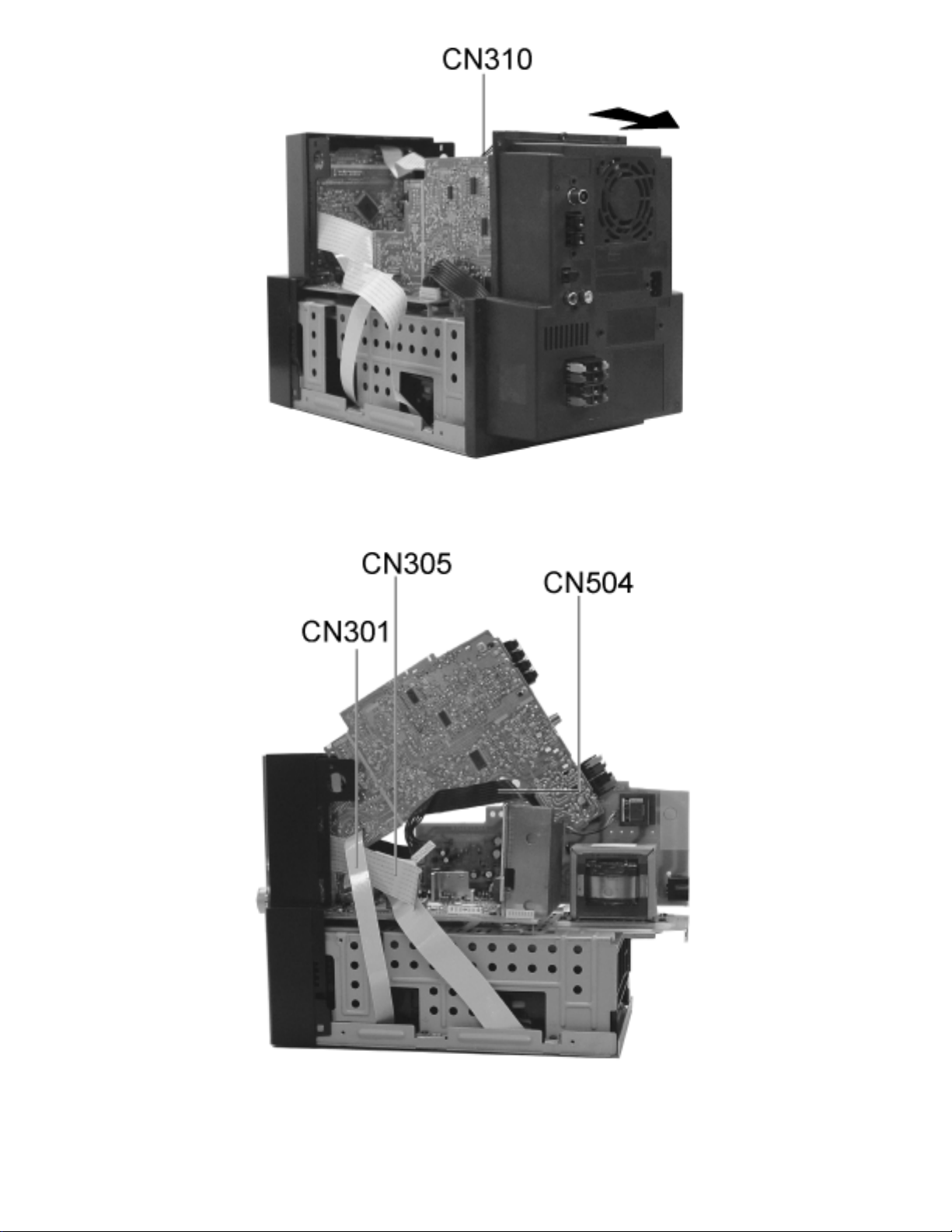
Step 5 Release the connector CN310 and pull out the back cover as the arrow shown.
Step 6 Release the connectors CN504, CN305 and CN301.
file:///C|/Documents%20and%20Settings/Administrator/Plocha/PANASONIC%20SA-PM27E/s0901000000.htm (3 of 9) [14.6.2003 18:30:10]
file:///C|/Documents%20and%20Settings/Administrator/Plocha/PANASONIC%20SA-PM27E/s0901000000.htm
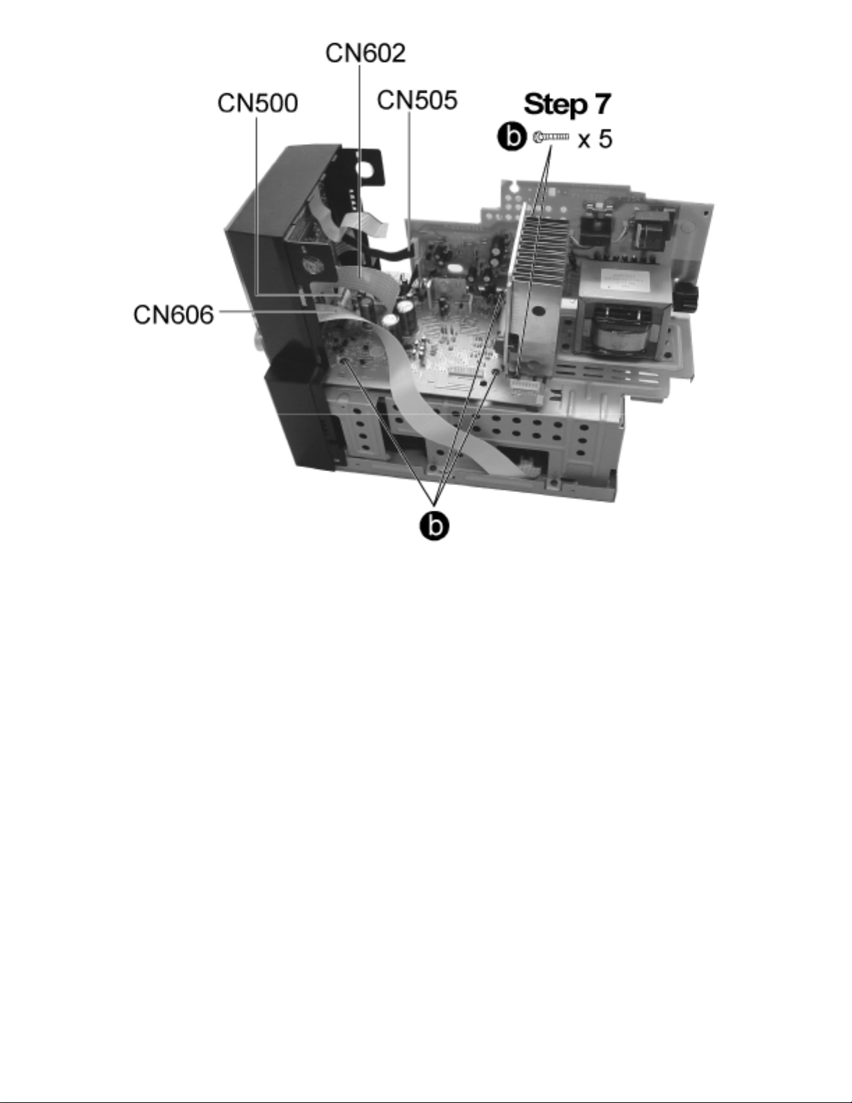
Step 7 Release the connectors CN606, CN602, CN505, CN500 and remove all the screws.
file:///C|/Documents%20and%20Settings/Administrator/Plocha/PANASONIC%20SA-PM27E/s0901000000.htm (4 of 9) [14.6.2003 18:30:10]
file:///C|/Documents%20and%20Settings/Administrator/Plocha/PANASONIC%20SA-PM27E/s0901000000.htm
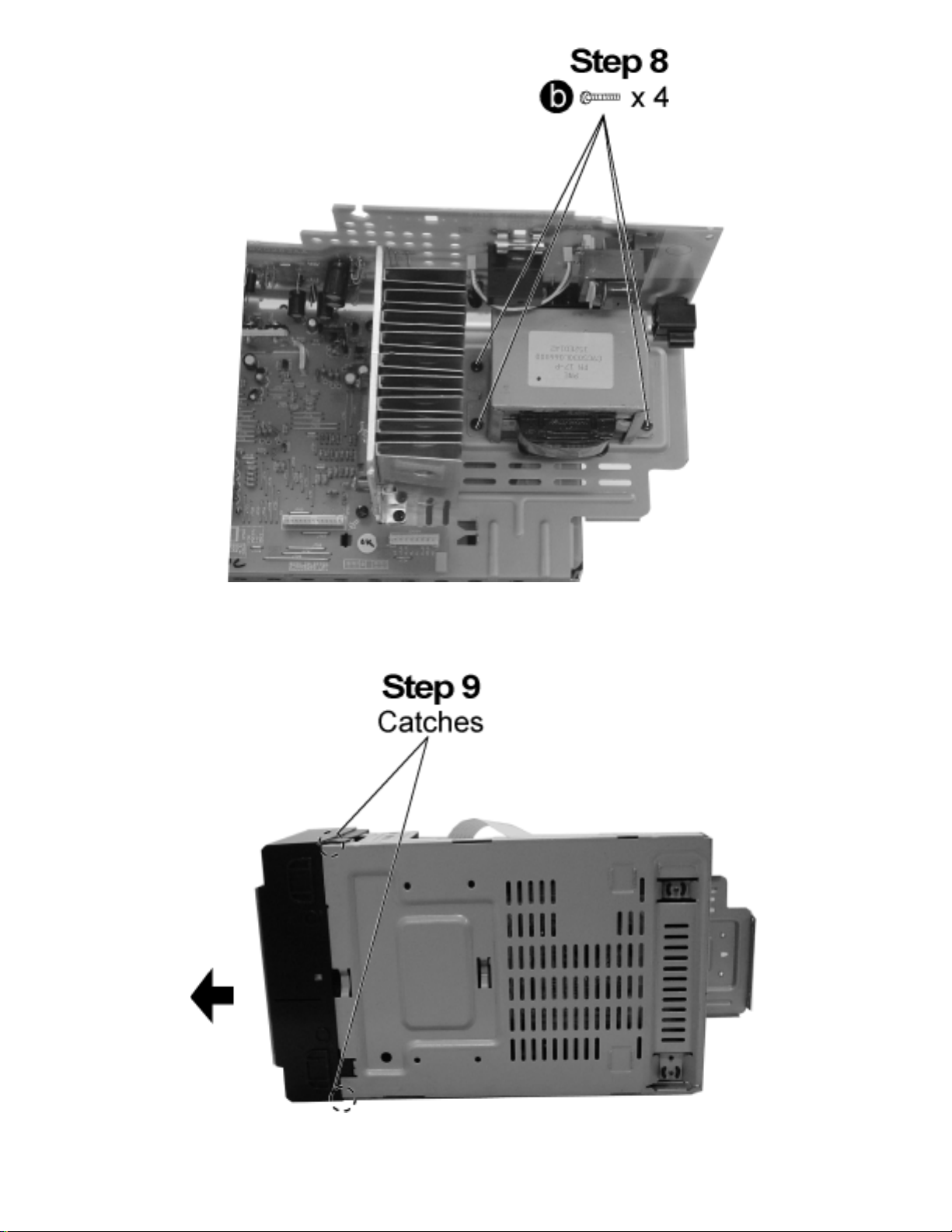
Step 8 Remove all the screws.
Step 9 Release the catches and pull out the front panel as the arrow shown.
file:///C|/Documents%20and%20Settings/Administrator/Plocha/PANASONIC%20SA-PM27E/s0901000000.htm (5 of 9) [14.6.2003 18:30:10]
file:///C|/Documents%20and%20Settings/Administrator/Plocha/PANASONIC%20SA-PM27E/s0901000000.htm
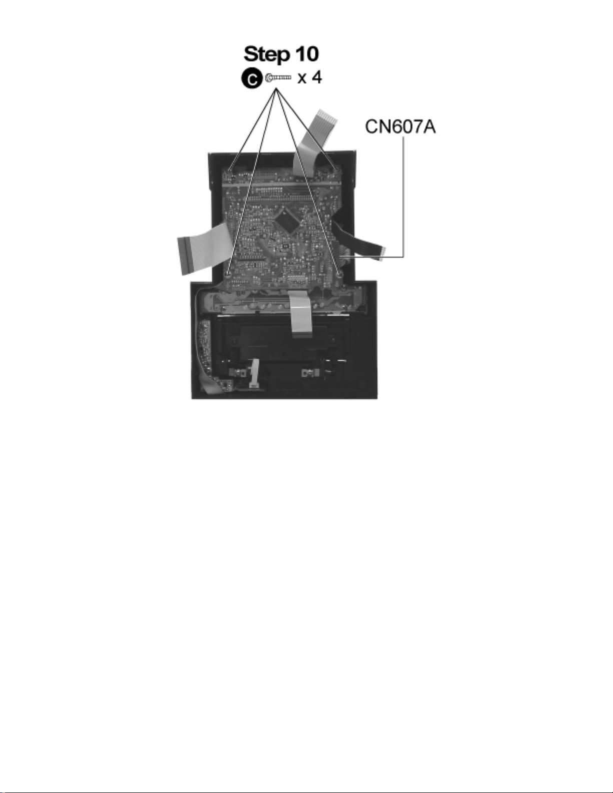
Step 10 Remove all the screws and release the connector CN607A.
file:///C|/Documents%20and%20Settings/Administrator/Plocha/PANASONIC%20SA-PM27E/s0901000000.htm (6 of 9) [14.6.2003 18:30:10]
 Loading...