

Panasonic SA NC9GC Diagram
A
A
A
DVD Stereo System
SA-NC9GC
SA-NC9GS
SA-NC9GCS
SA-NC9GN
Colour
(K)... Black Type
ORDER NO. MD0703039CE
Notes: This model’s DVD mechanism changer unit is DL2SV.
Specifications
n AMPLIFIER SECTION
RMS Output Power: Dolby Digital Mode
Front Ch 95 W per channel (3 Ω ), 1 kHz,
10% THD
Surround Ch 95 W per channel (3 Ω ), 1 kHz,
10% THD
Center Ch 95 W per channel (3 Ω ), 1 kHz,
10% THD
Subwoofer Ch 115 W per channel (3 Ω ), 100 Hz,
10% THD
Total RMS Dolby Digital mode power
590 W
PMPO output power (For GC, GS & GCS only)
6500 W
DIN Output Power: Dolby Digital Mode
Front Ch 65 W per channel (3 Ω ), 1 kHz,
10% THD
Surround Ch 65 W per channel (3 Ω ), 1 kHz,
10% THD
Center Ch 65 W per channel (3 Ω ), 1 kHz,
10% THD
Subwoofer Ch 75 W per channel (3 Ω ), 100 Hz,
10% THD
Total DIN Dolby Digital mode power
400 W
n FM/AM TUNER, TERMINALS SECTION
Preset stations FM 30 stations
Frequency Modulation (FM)
Frequency range 87.50 MHz to 108.00 MHz (50-kHz
Sensitivity 4.0 µV (IHF)
S/N 26 dB 2.2 µV
ntenna terminals 75 Ω (unbalanced)
mplitude Modulation (AM)
Frequency range
For GC, GS & GCS only 522 kHz to 1629 kHz (9-kHz step)
For GN only 522 kHz to 1629 kHz (9-kHz step)
M sensitivity S/N 20 dB at 999 kHz
Phone jack
Terminal Stereo, 3.5-mm jack
Mic jack (For GC, GS & GCS only)
Sensitivity 0.7 mV, 600 Ω
Terminal Mono, 6.3-mm jack (2 system)
Music Port jack (Front)
Sensitivity 100-mV, 10 kΩ
Terminal Stereo, 3.5-mm jack
USB jack
AM 30 stations
step)
520 kHz to 1630 kHz (10-kHz
step)
1000 µV/m
© 2007 Matsushita Electric Industrial Co. Ltd.. All
rights reserved. Unauthorized copying and
distribution is a violation of law.

A
SA-NC9GC / SA-NC9GS / SA-NC9GCS / SA-NC9GN
USB Standard USB 2.0 full speed 2.0
Media file format support MP3 (*.mp3), WMA (*.wma),
JPEG (*.Jpg, *JPEG), MPEG4
(*.asf)
USB device file system FAT16, FAT32
USB port power Max 500mA
n CASSETTE DECK SECTION
Track system 4-Track, 2 Channel
Head Record/Playback Solid Permalloy Head
Erasure Double Gap Ferrite Head
Motor DC Servo Motor
Recording System AC Bias 100 kHz
Erase System AC Erase 100 kHz
Tape Speed 4.8 cm/sec
Overall Frequency Response (+3, -6 dB) at DECK OUT
Normal 35 Hz to 14 kHz
S/N Ratio 50 dB (A weighted)
Wow and Flutter 0.18% (WRMS)
Fast Forward and Rewind Time Approx. 120 seconds with
C-60 cassette tape
n DISC SECTION
Disc played [8 cm or 12 cm]
(1) DVD (DVD-Video, DivX )
(2) DVD-RAM (DVD-VR, JPEG , MP3 , MPEG4 , DivX )
(3) DVD-R (DVD-Video, DVD-VR, JPEG , MP3 , MPEG4 ,
# 1,#2
DivX
)
#1,#2
#2,#3
#2,#4
#2,#3
#2,#4
#2,#5
#1,#2
#2,#5
(4) DVD-R DL (DVD-Video, DVD-VR)
(5) DVD-RW (DVD-Video, DVD-VR, JPEG , MP3 , MPEG4
2,#5
, DivX
# 1,#2
)
#2,#3
#2,#4
#
(6) +R/ +RW (Video)
(7) +R DL (Video)
#2,#4
(8) CD,CD-R/RW [CD-DA, Video CD, SVCD , MP3 , WMA ,
JPEG
# 2,#3
, MPEG4
# 2,#5
, DivX
# 1,#2
, HighMAT Level 2 (Audio and
#6
#2,#7
Image)]
#1
Plays all versions of DivX video (including DivX 6) with standard
®
®
playback of DivX®media files. Certified to the DivX Home Theater
Profile. GMC (Global Motion Compensation) is not supported.
#2
The total combined maximum number of recognizable audio,
picture and video contents and groups: 4000 audio, picture and video
contents and 400 groups.
#3
Exif Ver 2.1 JPEG Baseline files
Picture resolution: between 160 x 120 and 6144 x 4096 pixels
(Sub sampling is 4:0:0, 4:2:0, 4:2:2 or 4:4:4). Extremely long and
narrow pictures may not be displayed.
#4
MPEG-1 Layer 3, MPEG-2 Layer 3
#5
MPEG4 data recorded with the Panasonic SD multi cameras or
DVD video recorders.
Conforming to SD VIDEO specifications (ASF standard) / MPEG4
(Simple Profile) video system / G.726 audio system
#6
Conforming to IEC62107
#7
Windows Media Audio Ver. 9.0 L3
Not compatible with Multiple Bit Rate (MBR)
Pick up
Wavelength (DVD/CD) 662 nm/785 nm
Laser power (DVD/CD) CLASS 1 / CLASS 1M
udio output (Disc)
Number of channels (FL,FR,C,SL,SR,SW),5.1ch
n VIDEO SECTION
Video system PAL625/50, PAL525/60, NTSC
Composite video output
Output level 1Vp-p(75Ω)
Terminal Pin jack (1 system)
S-video output
Y output level 1Vp-p(75Ω)
C output level 0.3 Vp-p (75 Ω )(PAL)
0.286 Vp-p (75 Ω )(NTSC)
Terminal S terminal (1 system)
Component video output
[NTSC : 480p / 480i, PAL: 576p / 576i]
Y output level 1Vp-p(75Ω)
PBoutput level 0.525 Vp-p (75 Ω)
PRoutput level 0.525 Vp-p (75 Ω)
Terminal
Pin jack (Y: green, PB:blue,PR:red)(1system)
HDMI AV output
Terminal Type A connector (19-pin)
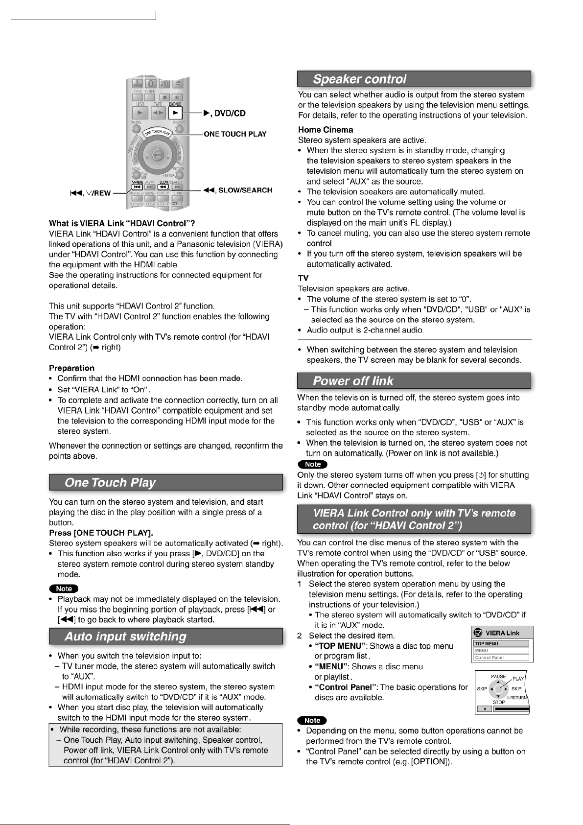
This unit supports “HDAVI Control 2” function.
n GENERAL
Power supply
For GC only AC 220 to 240 V, 50/60Hz
For GCS/GS only AC 110 to 127V/220 to 240 V,
50/60Hz
For GN only AC 230 to 240 V, 50Hz
Power consumption 165 W
Power consumption in standby mode:
0.9 W (approximate)
Dimensions (W x H x D) 205 x 385 x 342 mm
Mass appx. 7.1 kg
Operating temperatur e range +5to+35°C
Operating humidity range 5% to 90% RH (no condensation)
n SYSTEM
2
SA-NC9GC / SA-NC9GS / SA-NC9GCS / SA-NC9GN
Notes:
1. Specifications are subject to change without notice.
Mass and dimensions are approximate.
2. Total harmonic distortion is measured by the digital spectrum
analyzer.
For information on speaker system, please refer to the original
Service Manual (Order No. MD0703042CE) for SB-WNC9GC-K,
(Order No. MD0703040CE) for SB-PF9GC-K & (Order No.
MD0703041CE) for SB-NC9GC-K.
3
SA-NC9GC / SA-NC9GS / SA-NC9GCS / SA-NC9GN
CONTENTS
Page Page
1 Safety Precautions 6
1.1. General Guidelines
1.2. Safety Precaution for AC Power Supply Cord (For GS
only)
1.3. Before Use (For GS/GCS only)
1.4. Before Repair and Adjustment
1.5. Protection Circuitry
1.6. Safety Parts Information
2 Handling Precautions for Traverse Unit
2.1. Handling Optical Pickup
2.2. Replacing Precautions for Optical Pickup Unit
2.3. Grounding for Preventing Electrostatic Destruction
3 Precaution of Laser Diode
4 About Lead Free Solder (PbF)
4.1. Service caution based on legal restrictions
5 Accessories
6 Operation Procedures
6.1. Main Unit Key Buttons Operations
6.2. Remote Control Key Buttons Operations
6.3. Disc Information
6.4. DivX VOD Content
7 New Features
7.1. Using the VIERA Link 滴 DAVI Control 剩
8 About HighMAT
8.1. What 痴 HighMAT?
8.2. Why take advantage of HighMAT?
8.3. Benefits of HighMAT?
9 Self diagnosis and special mode setting
9.1. Service Mode Summary Table
9.2. Service Mode Table (Main Unit)
9.3. DVD Self Diagnostic Function - Error Code
9.4. Doctor Mode
9.5. Sales Demonstration Lock Function
10 Assembling and Disassembling
10.1. Caution
10.2. Disassembly flow chart
10.3. Main Parts Location
10.4. Disassembly of Top Cabinet
10.5. Disassembly of Rear Block
10.6. Disassembly of DVD Changer Unit (DL2SV) & HDMI
P.C.B.
10.7. Disassembly of Main P.C.B.
10.8. Disassembly of Front Panel
10.9. Disassembly of Power P.C.B. & Speaker P.C.B.
10.10. Replacement for Power Amp IC
11
12
12
13
15
16
17
18
20
21
22
23
23
23
24
27
27
27
35
38
49
50
50
52
53
54
54
55
56
56
57
58
6
7
7
7
7
8
9
9
9
9
10.11. Disassembly of Panel P.C.B.
10.12. Disassembly of Sub Panel P.C.B.
10.13. Disassembly of Deck Mechanism Unit
10.14. Disassembly of Deck P.C.B.
10.15. Disassembly of Traverse Unit
10.16. Disassembly of Deck Mechanism Main Components
10.17. Disassembly of Deck Mechanism P.C.B.
10.18. Disassembly of cassette lid
10.19. Rectification for tape jam problem
10.20. Stacking of Surround Speaker & Speakers to enjoy Bi-
Amp TS Mode
11 Service Positions
11.1. Checking and Repairing of Main P.C.B. & DVD Module
P.C.B.
11.2. Checking and Repairing of HDMI P.C.B.
11.3. Checking and Repairing of Deck & Deck Mechanism
P.C.B.
11.4. Checking and Repairing of Power & Speaker P.C.B.
11.5. Checking and Repairing of Panel P.C.B.
12 Procedure for Checking Operation of Individual Parts of Deck
Mechanism Unit
12.1. Operation Check with Cassette Tape
12.2. Operation Check without Cassette Tape
13 Measurement And Adjustments
13.1. Cassette Deck Section
14 Voltage and Waveform Chart
14.1. DVD Module P.C.B.
14.2. Main P.C.B.
14.3. Panel P.C.B.
14.4. Power P.C.B.
14.5. Sub Heat Sink P.C.B.
14.6. Sub Panel P.C.B.
14.7. Transformer P.C.B.
14.8. Tray Loading P.C.B.
14.9. Deck P.C.B. & Deck Mechanism P.C.B.
14.10. Waveform Chart
15 Wiring Connection Diagram
16 Block Diagram
16.1. DVD
16.2. Main
16.3. Panel/Sub Panel/USB Relay
16.4. Power
16.5. Transformer
16.6. Deck/Deck Mechanism/Tray Loading
17 Notes of Schematic Diagrams
59
59
60
60
60
63
65
65
66
66
68
68
69
70
71
72
73
73
73
75
75
77
77
79
81
82
82
82
83
83
83
84
87
89
89
92
95
96
97
98
99
4

SA-NC9GC / SA-NC9GS / SA-NC9GCS / SA-NC9GN
18 Schematic Diagram 101
18.1. (A) DVD Module (DV5.0) Circuit
18.2. (A) DVD Module (HDMI) Circuit
18.3. (B) Main Circuit
18.4. (C) Panel Circuit
18.5. (D) Sub Panel Circuit
18.6. (E) Power Circuit
18.7. (F) Speaker Circuit
18.8. (G) Transformer Circuit
18.9. (H) Sub Heat Sink Circuit
18.10. (I) Deck Circuit
101
105
106
110
111
112
114
115
116
117
18.11. (J) Deck Mechanism Circuit, (K) Relay Circuit & (L) Tray
Loading Circuit
18.12. Optical Pickup Unit Circuit
19 Printed Circuit Board
19.1. (A) DVD Module P.C.B. (Side A & B )
19.2. (B) Main P.C.B.
19.3. (C) Panel P.C.B. & (D) Sub Panel P.C.B.
118
119
121
122
123
124
19.4. (E) Power P.C.B., (F) Speaker P.C.B., (G) Transformer
P.C.B. & (H) Sub Heat Sink P.C.B.
19.5. (I) Deck P.C.B. , (J) Deck Mechanism P.C.B., (K) Relay
P.C.B. & (L) Tray Loading P.C.B.
20 Basic Troubleshooting Guide
20.1. Basic Troubleshooting Guide for Traverse Unit (DVD
Module P.C.B.)
20.2. Basic Troubleshooting Guide for HDMI AV output
21 Illustration of ICs, Transistors and Diodes
22 Terminal Function of IC
131
22.1. IC2600 (C2CBYY0 00451
) System Microprocessor
23 Exploded Views
23.1. Cabinet Parts Location
23.2. Deck Mechanism Parts Location (RAA4111-S)
23.3. Packaging
24 Replacement Parts List
125
126
127
127
127
129
131
133
133
136
137
139
5
SA-NC9GC / SA-NC9GS / SA-NC9GCS / SA-NC9GN
1 Safety Precautions
1.1. General Guidelines
1. When servicing, observe the original lead dress. If a short circuit is found, replace all parts which have been overheated or
damaged by the short circuit.
2. After servicing, see to it that all the protective devices such as insulation barriers, insulation papers shields are properly
installed.
3. After servicing, make the following leakage current checks to prevent the customer from being exposed to shock hazards.
1.1.1. Leakage Current Cold Check
1. Unplug the AC cord and connect a jumper between the two prongs on the plug.
2. Measure the resistance value, with an ohmmeter, between the jumpered AC plug and each exposed metallic cabinet part on
the equipment such as screwheads, connectors, control shafts, etc. When the exposed metallic part has a return path to the
chassis, the reading should be between 1MΩ and 5.2MΩ.
When the exposed metal does not have a return path to the chassis, the reading must be
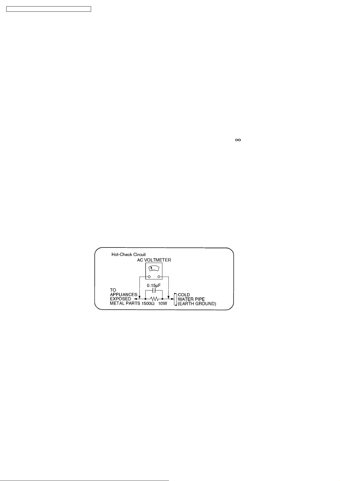
1.1.2. Leakage Current Hot Check
(See Figure 1)
1. Plug the AC cord directly into the AC outlet. Do not use an isolation transformer for this check.
2. Connect a 1.5kΩ, 10 watts resistor, in parallel with a 0.15µF capacitor, between each exposed metallic part on the set and a
good earth ground such as a water pipe, as shown in Figure 1.
3. Use an AC voltmeter, with 1000 ohms/volt or more sensitivity, to measure the potential across the resistor.
4. Check each exposed metallic part, and measure the voltage at each point.
5. Reverse the AC plug in the AC outlet and repeat each of the above measurements.
6. The potential at any point should not exceed 0.75 volts RMS. A leakage current tester (Simpson Model 229 or equivalent) may
be used to make the hot checks, leakage current must not exceed 1/2 milliamp. In case a measurement is out of the limits
specified, there is a possibility of a shock hazard, and the equipment should be repaired and rechecked before it is returned to
the customer.
.
Figure 1
6
SA-NC9GC / SA-NC9GS / SA-NC9GCS / SA-NC9GN
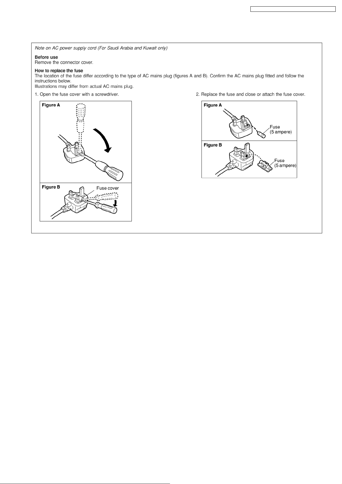
1.2. Safety Precaution for AC Power Supply Cord (For GS only)
1.3. Before Use (For GS/GCS only)
Be sure to disconnect the mains cord before adjusting the voltage selector.
Use a minus(-) screwdriver to set the voltage selector (on the rear panel) to the voltage setting for the area in which the unit will
be used. (If the power supply in your area is 110V or 127V, set to the “127V” position.)
Note that this unit will be seriously damaged if this setting is not made correctly. (There is no voltage selector for some countries,
the correct voltage is already set.)
1.4. Before Repair and Adjustment
Disconnect AC power, discharge Power Supply Capacitors C5951 through a 10Ω, 5W resistor to ground.
DO NOT SHORT-CIRCUIT DIRECTLY (with a screwdriver blade, for instance), as this may destroy solid state devices.
After repairs are completed, restore power gradually using a variac, to avoid overcurrent.
Current consumption at AC 110 ~ 127V, 50 / 60 Hz in NO SIGNAL (vol. min, at CD mode) should be ~900mA. [For GCS/GS only]
Current consumption at AC 220 ~ 240V, 50 / 60 Hz in NO SIGNAL (vol. min, at CD mode) should be ~500mA . [For GC/GCS/GS
only]
Current consum ption at AC 230 ~ 240V, 50 Hz in NO SIGNAL (vol. min, at CD mode) should be ~500mA . [For GN only]
1.5. Protection Circuitry
The protection circuitry may have operated if either of the following conditions are noticed:
· No sound is heard when the power is turned on.
· Sound stops during a performance.
The function of this circuitry is to prevent circuitry damage if, for example, the positive and negative speake r connection wires are
“shorted”, or if speaker systems with an impedance less than the indicated rated impedance of the amplifier are used.
If this occurs, follow the procedure outlines below:
1. Turn off the power.
2. Determine the cause of the problem and correct it.
3. Turn on the power once again after one minute.
7
SA-NC9GC / SA-NC9GS / SA-NC9GCS / SA-NC9GN
Note :
When the protection circuitry functions, the unit will not operate unless the power is first turned off and then on again.
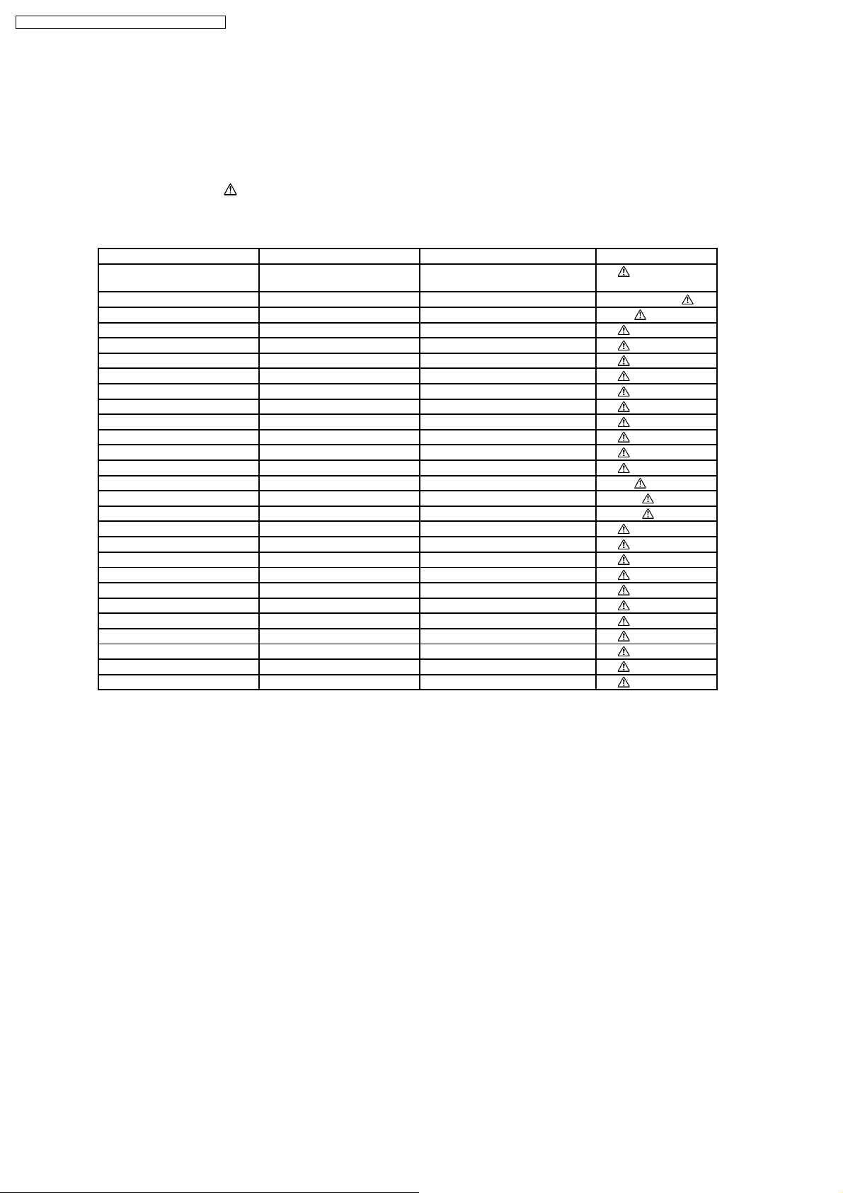
1.6. Safety Parts Information
Safety Parts List:
There are special components used in this equipment which are important for safety.
These parts are marked by
should be replaced with manufacturer’s specified parts to prevent shock, fire or other hazards. Do not modify the original design
without permission of manufacturer.
Reference No. Part No. Part Name & Description Remarks
360 RAE2024Z-S TRAVERSE UNIT (AFTER
A2 K2CQ2CA00002 AC CORD [M]GC/GS/GCS
A2 K2CJ2DA00010 AC CORD [M]GN
C5251 F2A1V4710036 470 35V [M]
C5252 F2A1V4710036 470 35V [M]
C5351 F2A1V4710036 470 35V [M]
C5352 F2A1V4710036 470 35V [M]
C5451 F2A1V4710036 470 35V [M]
C5452 F2A1V4710036 470 35V [M]
C5512 F2A1V1020084 1000 35V [M]
C5513 F2A1V1020084 1000 35V [M]
C5951 ECQU2A104MLC 0.1 100V [M]
D5744 B0JCAE000001 DIODE [M]
F1 K5D252BLA013 2.5A FUSE [M]GC
F1 K5D502BLA013 FUSE [M]GCS
F2 K5D252BLA013 2.5A FUSE [M]GCS
FP5920 K5G103A00019 FUSE PROTECTOR [M]
FP5940 K5G103A00019 FUSE PROTECTOR [M]
FP5950 K5G502A00039 FUSE PROTECTOR [M]
RL5950 K6B1AEA00003 MAGNETRELAYS [M]
JK5950 K2AA2B000011 JK AC INLET [M]
L5950 ELF15N035AN LINE FILTER [M]
L5951 ELF15N035AN LINE FILTER [M]
T5950 G4CYAYY00141 TRANSFORMER [M]
T5951 G4C2AAJ00005 BACK-UP TRANSFORMER [M]
Z5950 ERZV10V511CS ZENER [M]
R5271 ERJ3GEYJ102V 1K 1/16W [M]
in the Schematic Diagrams & Replacement Parts List. It is essential that these critical parts
Table 1
[M]
ALIGNMENT)
8
SA-NC9GC / SA-NC9GS / SA-NC9GCS / SA-NC9GN
2 Handling Precautions for Traverse Unit
The laser diode used inside optical pickup could be destroyed due to static electricity as a potential difference is caused by
electrostatic load discharged from clothes or human body. Handling the parts carefully to avoid electrostatic destruction during
repair.
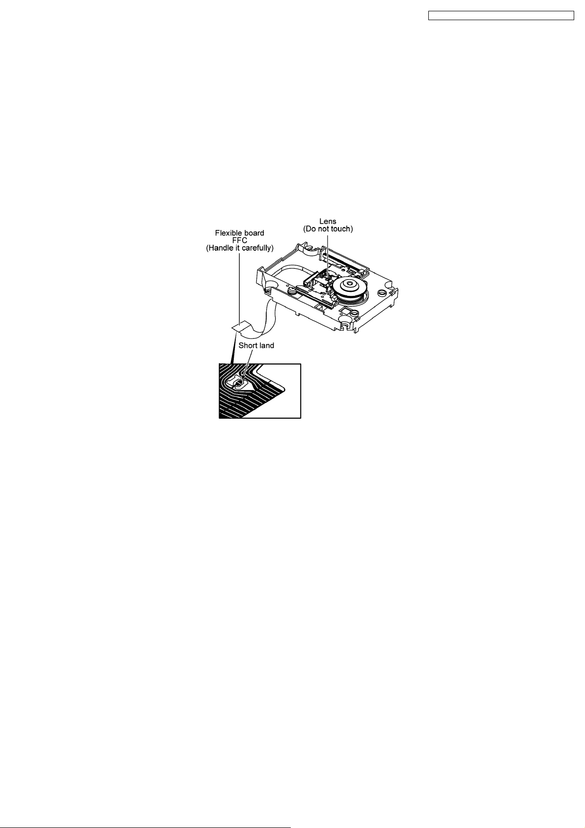
2.1. Handling Optical Pickup
1. Do not impact on optical pickup as the unit structurally uses an extremely precise technology.
2. Short-circuit the flexible cable of optical pickup remove from the circuit board using a short-circuit pin or clip in order to prevent
laser diode from electrostatic destruction (Refer to Fig. 3.1 and Fig. 3.2)
3. Do not handle flexible cables forcibly as this may cause snapping. Handle the parts carefully (Refer to Fig. 3.1)
4. A new optical pickup is equipped with an anti-static flexible cable. After replacing and connecting to the flexible board, cut the
anti-static flexible cable. (Refer to Fig. 3.1)
Fig. 3.1
2.2. Replacing Precautions for Optical Pickup Unit
CD/DVD Optical Pickup
The optical pickup by which part supply was carried out attaches the short clip to the flexible board for laser diode electrostatic
discharge damage prevention. Please remove the short clip and be sure to check that the short land is open, before connecting.
(Please remove solder, when the short land short-circuits.)
2.3. Grounding for Preventing Electrostatic Destruction
1. Human body grounding
Use the anti-static wrist strap to discharge the static electricity accumulated in your body. (Refer to Fig. 3.2)
2. Work place grounding
Place a conductive material (conductive sheet) or ironboard where optical pickup is placed. (Refer to Fig. 3.2)
Note :
Keep your clothes away from optical pickup as wrist strap does not release the static electricity charged in clothes.
9

SA-NC9GC / SA-NC9GS / SA-NC9GCS / SA-NC9GN
Fig. 3.2
10
SA-NC9GC / SA-NC9GS / SA-NC9GCS / SA-NC9GN
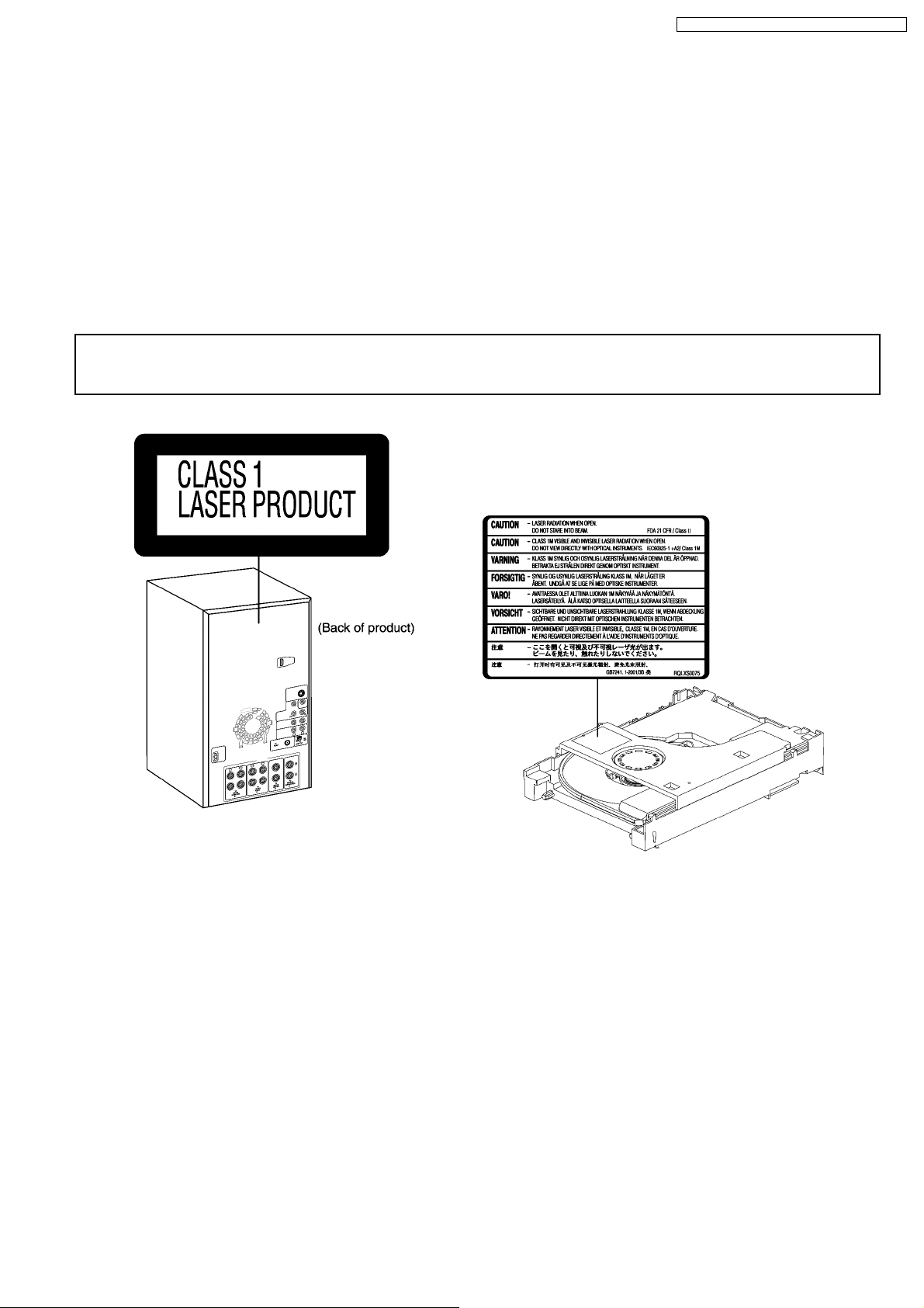
3 Precaution of Laser Diode
Caution :
This product utilizes a laser diode with the unit turned "ON", invisible laser radiation is emitted from the pick up lens.
Wavelength : 785 nm(CD)/662 nm(DVD)
Maximum output radiation power from pick up : 100 µW/VDE
Laser radiation from pick up unit is safety level, but be sure the followings:
1. Do not disassemble the optical pick up unit, since radiation from exposed laser diode is dangerous.
2. Do not adjust the variable resistor on the pick up unit. It was already adjusted.
3. Do not look at the focus lens using optical instruments.
4. Recommend not to look at pick up lens for a long time.
CAUTION!
THIS PRODUCT UTILIZES A LASER.
USE OF CONTROLS OR ADJUSTMENTS OR PERFORMANCE OF PROCEDURES OTHER THAN THOSE SPECIFIED HEREIN MAY RESULT
IN HAZARDOUS RADIATION EXPOSURE.
n Use of Caution Labels
11
SA-NC9GC / SA-NC9GS / SA-NC9GCS / SA-NC9GN
4 About Lead Free Solder (PbF)
4.1. Service caution based on legal restrictions
4.1.1. General description about Lead Free Solder (PbF)
The lead free solder has been used in the mounting process of all electrical components on the printed circuit boards used for this
equipment in considering the globally environmental conservation.
The normal solder is the alloy of tin (Sn) and lead (Pb). On the other hand, the lead free solder is the alloy mainly consists of tin
(Sn), silver (Ag) and Copper (Cu), and the melting point of the lead free solder is higher approx.30 degrees C (86°F) more than that
of the normal solder.
Definition of PCB Lead Free Solder being used
The letter of “PbF” is printed either foil side or components side on the PCB using the lead free solder.
(See right figure)
Service caution for repair work using Lead Free Solder (PbF)
· The lead free solder has to be used when repairing the equipment for which the lead free solder is used.
(Definition: The letter of “PbF” is printed on the PCB using the lead free solder.)
· To put lead free solder, it should be well molten and mixed with the original lead free solder.
· Remove the remaining lead free solder on the PCB cleanly for soldering of the new IC.
· Since the melting point of the lead free solder is higher than that of the normal lead solder, it takes the longer time to melt
the lead free solder.
· Use the soldering iron (more than 70W) equipped with the temperature control after setting the temperature at 350±30
degrees C (662±86°F).
Recommended Lead Free Solder (Service Parts Route.)
· The following 3 types of lead free solder are available through the service parts route.
RFKZ03D01K-----------(0.3mm 100g Reel)
RFKZ06D01K-----------(0.6mm 100g Reel)
RFKZ10D01K-----------(1.0mm 100g Reel)
Note
* Ingredient: tin (Sn), 96.5%, silver (Ag) 3.0%, Copper (Cu) 0.5%, Cobalt (Co) / Germanium (Ge) 0.1 to 0.3%
12
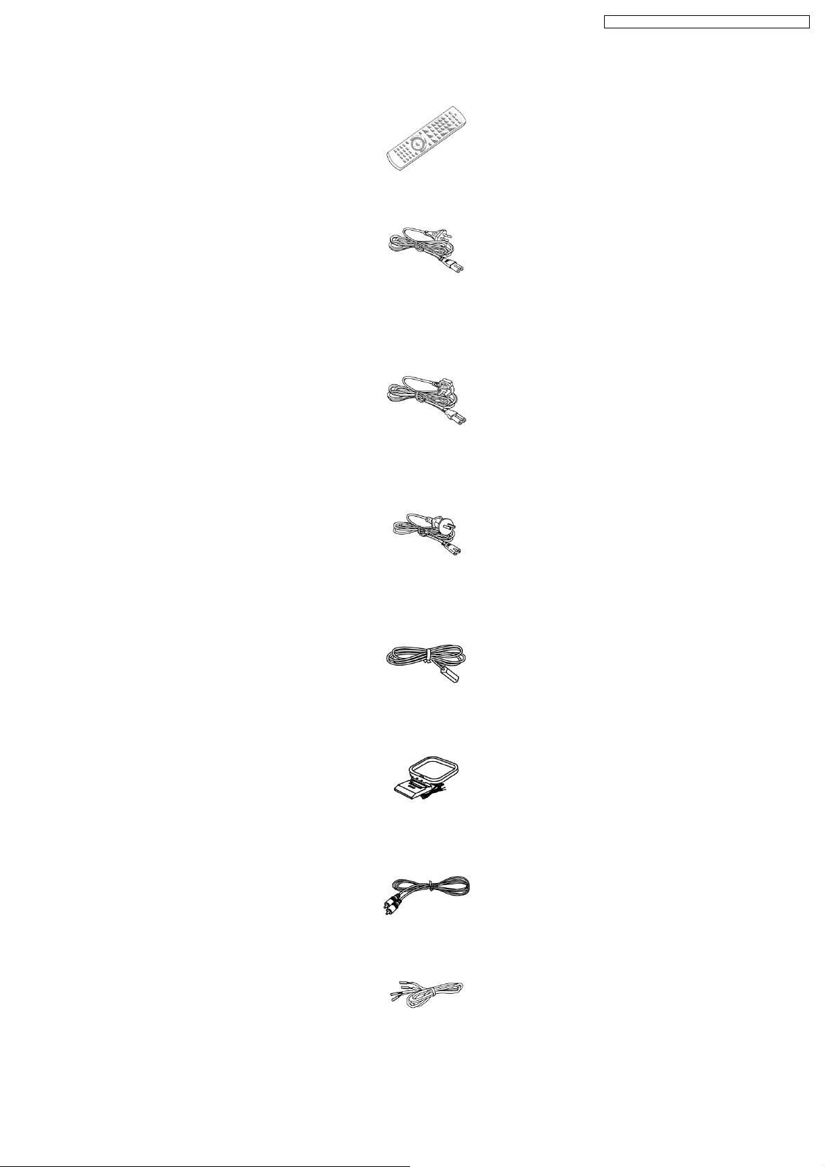
5 Accessories
SA-NC9GC / SA-NC9GS / SA-NC9GCS / SA-NC9GN
Remote control
AC power
supply cord
(For GC/GCS
only)
AC power
supply cord (For
GS only)
AC power
supply cord
(For GN only)
FM indoor
antenna
AM loop
antenna
Video cable
Speaker cables
13
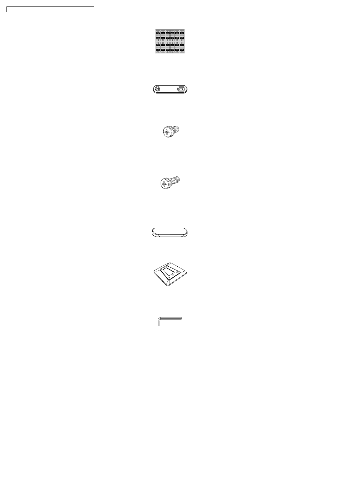
SA-NC9GC / SA-NC9GS / SA-NC9GCS / SA-NC9GN
Speaker cable
sticker
Metal brackets (x
6)
Short
screws (x
12)
Long
screws (x
4)
Lock covers (x 6)
Base stands (x
2)
Allen Key
14

6 Operation Procedures
SA-NC9GC / SA-NC9GS / SA-NC9GCS / SA-NC9GN
15
SA-NC9GC / SA-NC9GS / SA-NC9GCS / SA-NC9GN
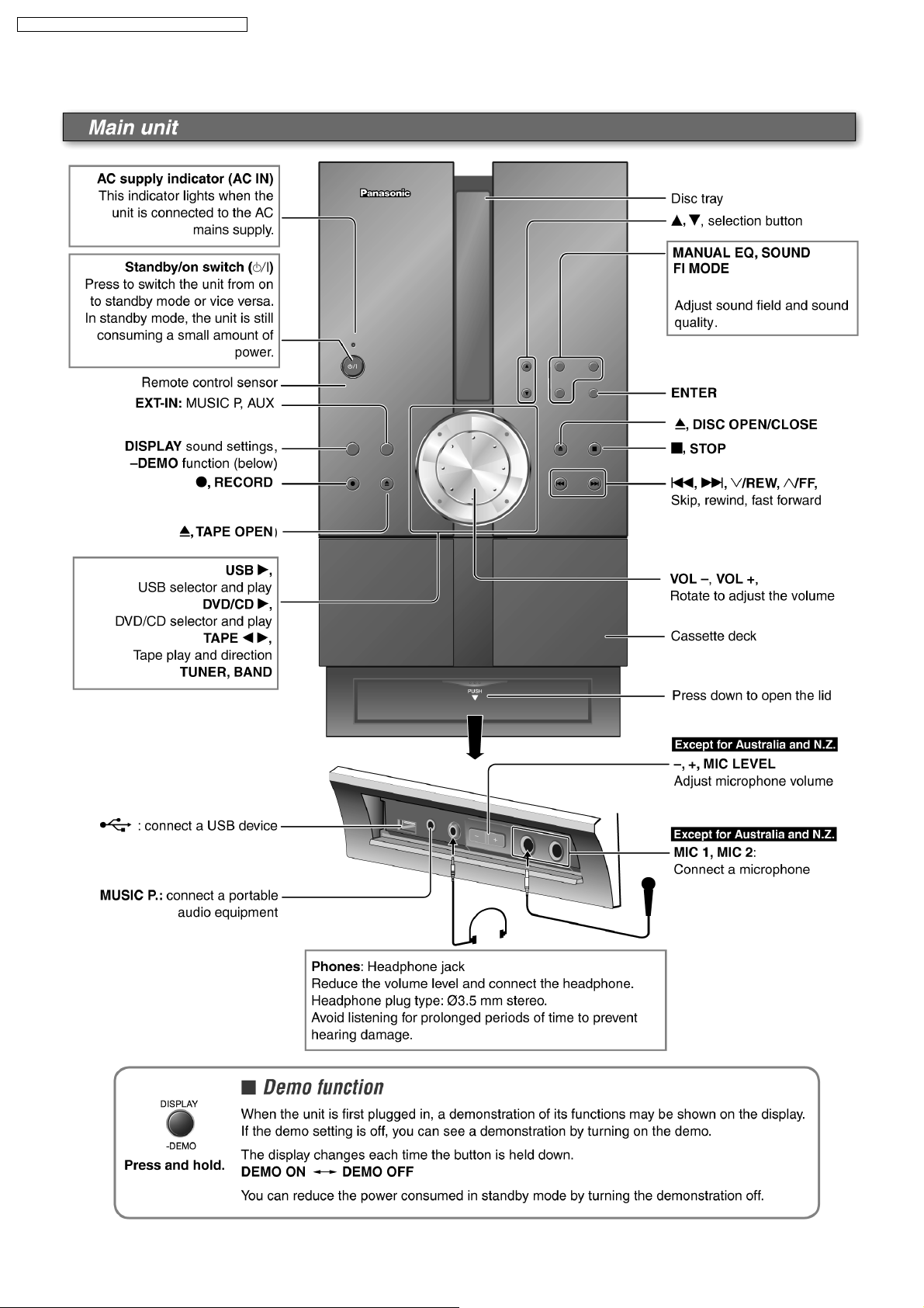
6.1. Main Unit Key Buttons Operations
16
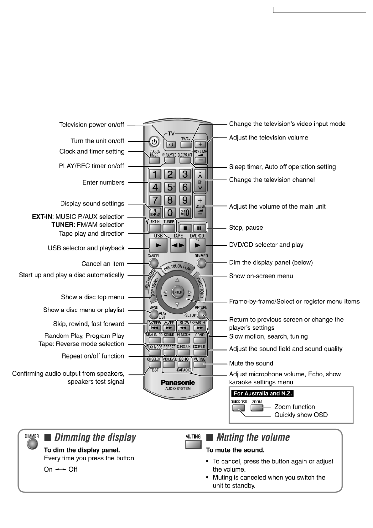
6.2. Remote Control Key Buttons Operations
SA-NC9GC / SA-NC9GS / SA-NC9GCS / SA-NC9GN
17
SA-NC9GC / SA-NC9GS / SA-NC9GCS / SA-NC9GN
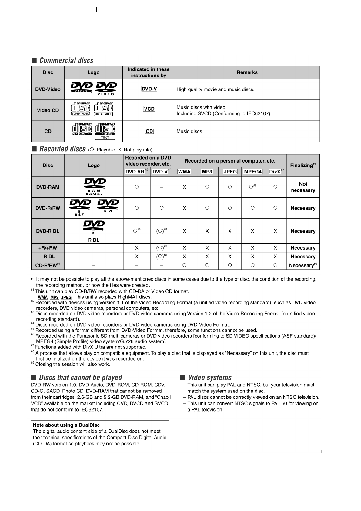
6.3. Disc Information
6.3.1. Disc Playability
18
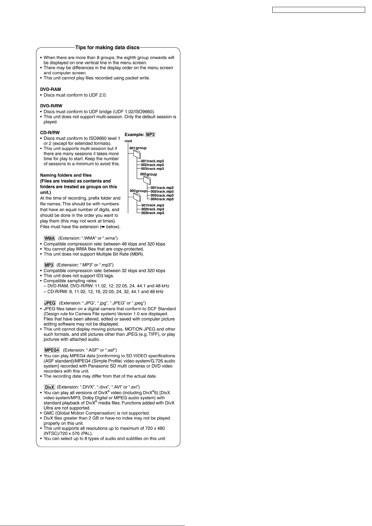
6.3.2. To Play MP3/ WMA and still Pictures (JPEG)
SA-NC9GC / SA-NC9GS / SA-NC9GCS / SA-NC9GN
19
SA-NC9GC / SA-NC9GS / SA-NC9GCS / SA-NC9GN
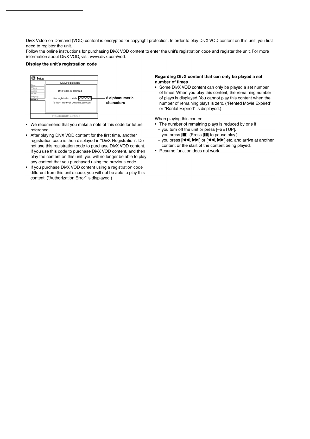
6.4. DivX VOD Content
20

7 New Features
SA-NC9GC / SA-NC9GS / SA-NC9GCS / SA-NC9GN
21
SA-NC9GC / SA-NC9GS / SA-NC9GCS / SA-NC9GN
7.1. Using the VIERA Link “HDAVI Control™”
22
SA-NC9GC / SA-NC9GS / SA-NC9GCS / SA-NC9GN
8 About HighMAT
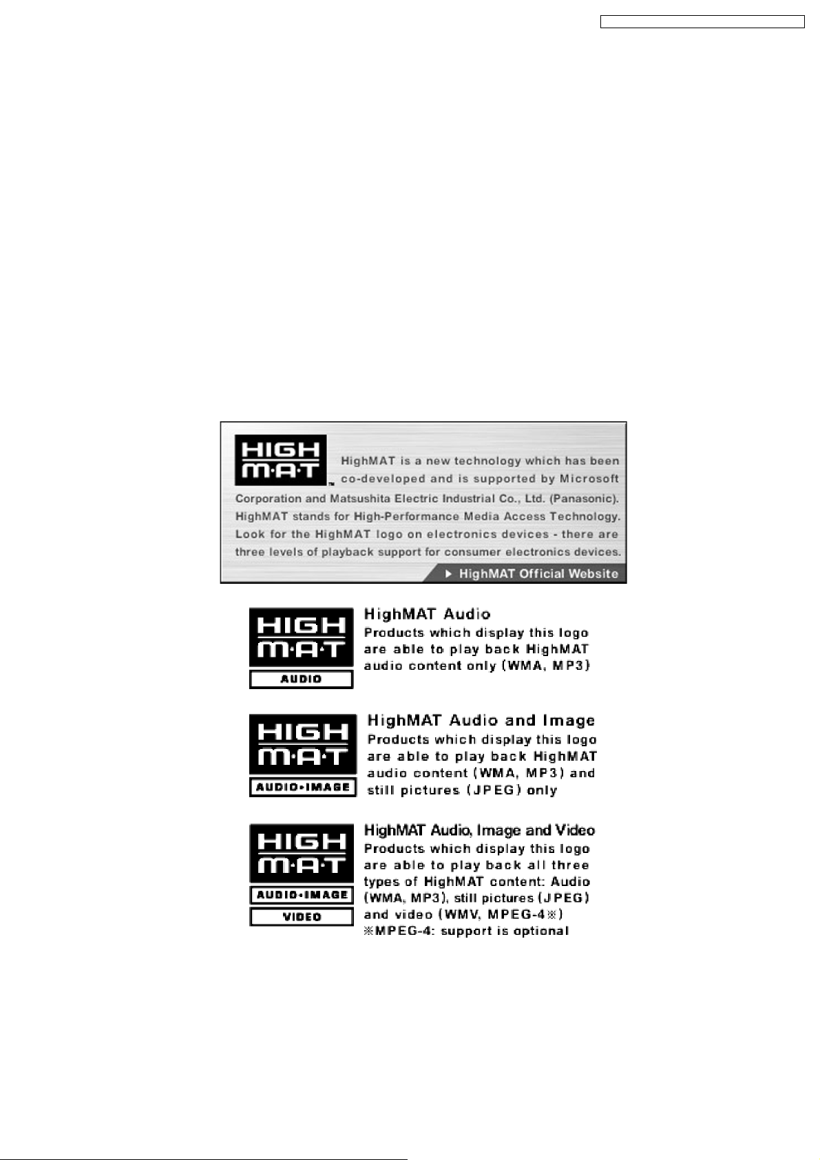
8.1. What’s HighMAT?
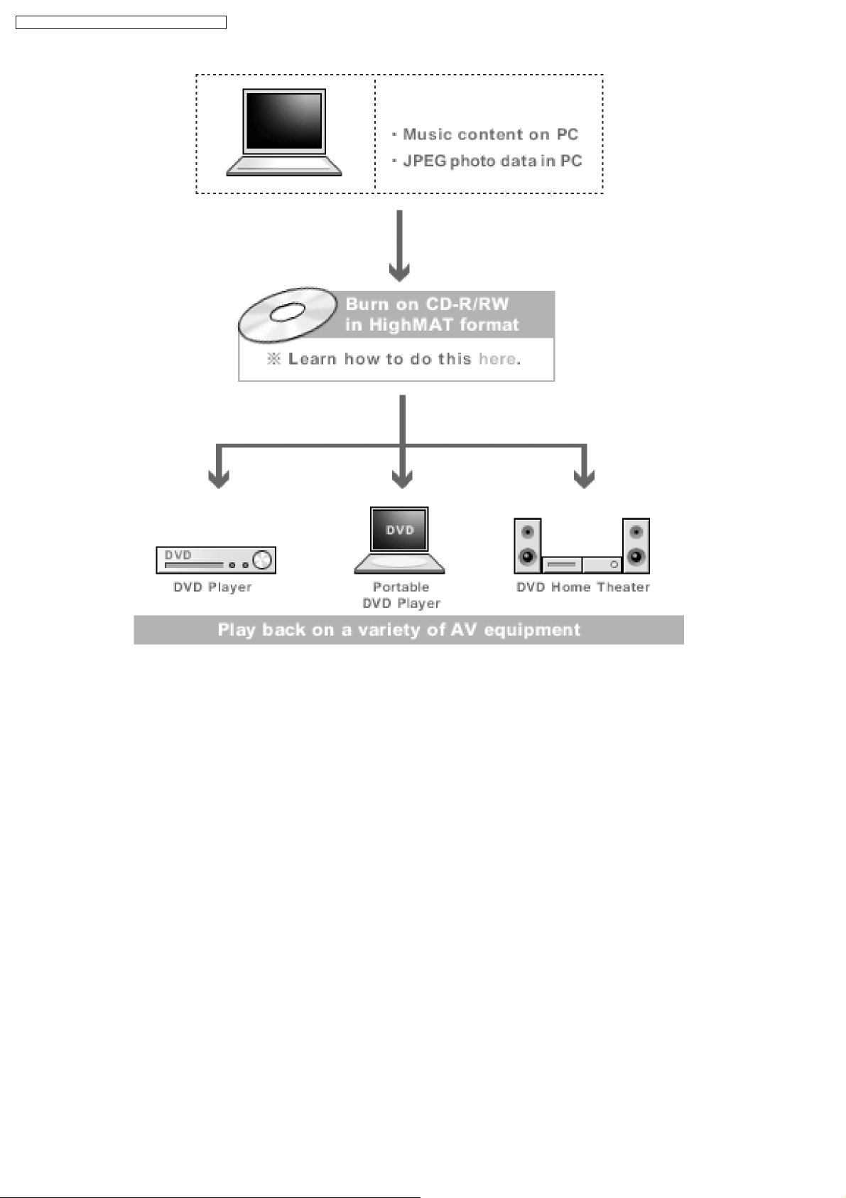
Consumers worldwide are using PCs to create their own collections of music, photos and even video by burning them onto CDs.
But how these collections can be experienced across different devices can be confusing to navigate, time consuming to access for
a DVD player, and be incomplete in terms of music information available to the customer.
HighMAT offers a solution to this growing consumer problem. HighMAT dramatically improves the digital media experience on
consumer electronic devices by delivering a simple, standardized approach that allows consumers who have created personal
collections of digital music, photography and video on their PC to:
>> Create a HighMAT CD or DVD which can be easily played back on consum er electronics devices such as CD and DVD players ,
and car stereos.
>> Move digital media files (using recordable media such as CD-R and CD-RW) between the PC and various playback devices
such as CD and DVD players.
A new standard for creating personal media on consumer electronic devices, HighMAT enable easier and more seamless
interoperability between Windows PCs and devices designed for your living room, or the car.
8.2. Why take advantage of HighMAT?
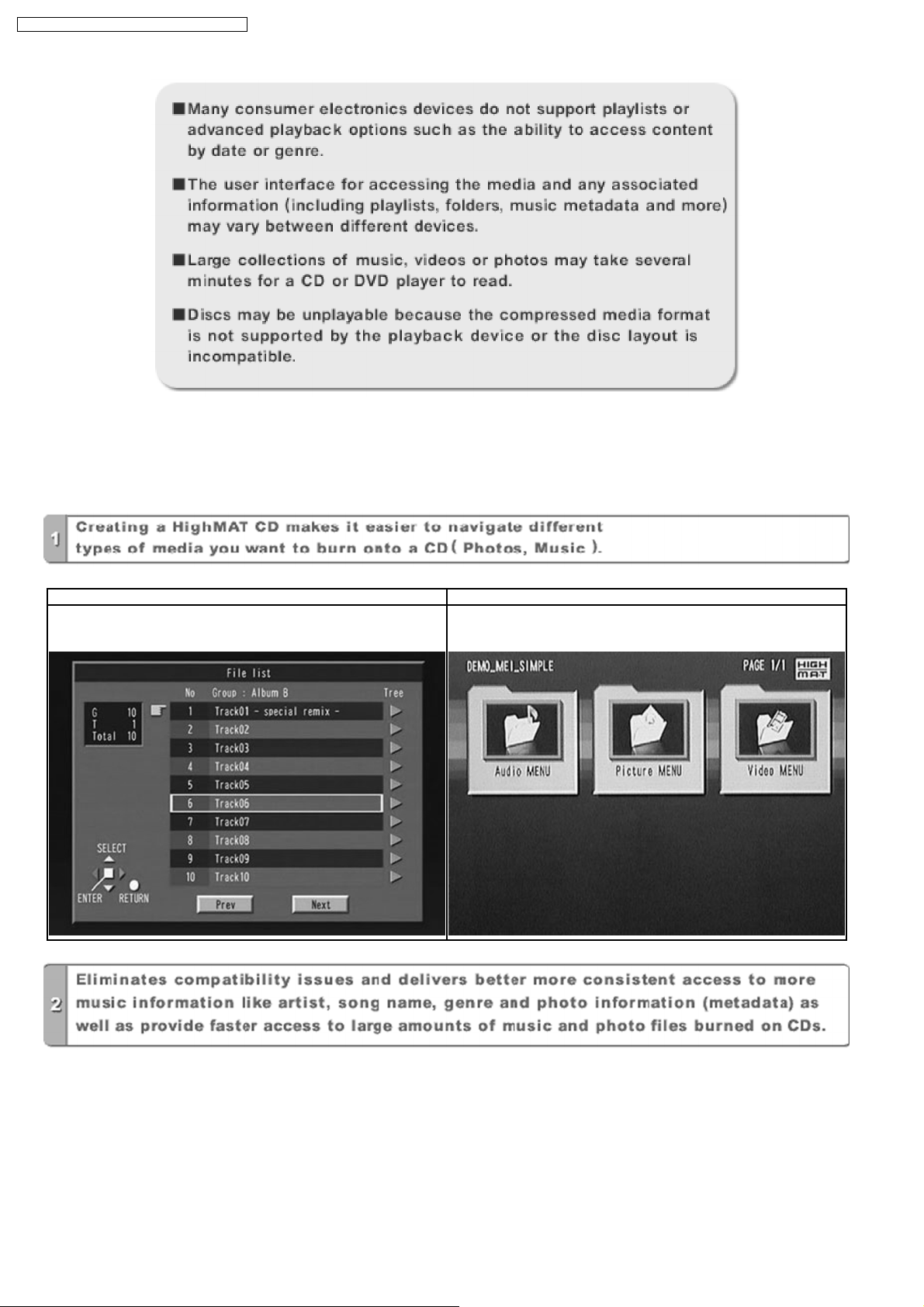
A Problem Defined:Toda y, when consumers create their own digital audio, video or photo collections on CD-R or other physical
formats, there are numerous, inconsistent ways that devices read the data. For the consumer, the playba ck experie nce can be
confusing:
23
SA-NC9GC / SA-NC9GS / SA-NC9GCS / SA-NC9GN
A Solution Created: HighMAT delivers a better digital media access experience by creating a standard approach for PCs to
structure digital media on various physical formats and for playback devices to read the data.
8.3. Benefits of HighMAT?
Conventional HighMAT
Even though DVD player is CD-R/RW compatible, the inconsistent ways
that various DVD players can read the music or photos files often leads
to a confusing and inconsistant playback experince.
HighMAT compatible products play content back with consistent
interface. This includes products which are JPEG compatible products
without HighMAT support.
24
SA-NC9GC / SA-NC9GS / SA-NC9GCS / SA-NC9GN
25
SA-NC9GC / SA-NC9GS / SA-NC9GCS / SA-NC9GN
HighMAT is now available for CD Burning and in Leading DVD PlayersHighMAT is a new technology that is now available in leading
software and consumer electronic devices to dramatically improve the digital media experience when you create homemade
CDsHighMAT delivers a simple, standardized way for PC software and consumer electronics devices to talk to each other and work
better together.
When you create your homemade CDs with software that supports HighMAT CD burning, and then play them back on a DVD
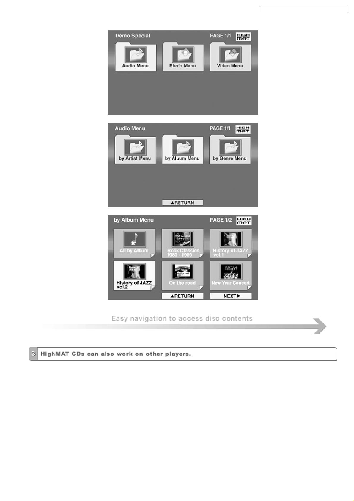
player that supports HighMAT, you get better, easier navigation. You get folders you can access with a single click of your DVD
player´s remote control. You can view important information about your music like full song names, artist titles, album names and
genre. And you can get faster startup on your home entertainment device.
To enjoy the benefits of HighMAT, all you need is software that supports HighMAT for CD burning of music or photos, as well as
a home entertainment device like a DVD player that supports HighMAT for playback. Always look for the HighMAT logo on your
software or home entertainment device to ensure it supports the HighMAT experience.
26
SA-NC9GC / SA-NC9GS / SA-NC9GCS / SA-NC9GN
9 Self diagnosis and special mode setting
This unit is equipped with functions for checking and inspecting namely : Self-Diagnostic and Test Mode.
9.1. Service Mode Summary Table
The service modes can be activated by pressing various button combination on the player and remote control unit.
Below is the summary of major checking:
Player buttons Remote control unit
buttons
[ ] 0 Error code check. (Refer to the section, “9.2.1 Service
5 Jitter checking.
FUNCTIONS DVD laser drive current check.
PAUSE Initial setting of laser drive current
1 ADSC internal RAM data check. (Refer to the section, “9.2.2 Service
3 CD laser drive current check.
7 Micro-processor firmware version check.
6 Region display and mode. (Refer to the section, “9.2.3 Service
8 DVD (HDMI) module firmware version check.
Initialization of the player (factory setting is restored.)
Used after replacement of micro-computer (DV 5.0 LSI
IC (IC8611), FLASH ROM IC, EEPROM and HDMI
module.
MENU Communication error display.
TOP MENU ECC error check.
EQ CPPM/CRM keys check.
ENTER DVD (HDMI) Module P.C.B. reset.
Timer 1 check. (Refer to the section, “10.2.4 Service
Timer 1 reset. (While in Timer 1 check mode)
Application Note
Mode Table 1” for more information).
Mode Table 2” for more information).
Mode Table 3” for more information).
Mode Table 4” for more information).
Timer 2 check.
Timer 2 reset. (While in Timer 2 check mode)
Note:
An error code will be cancelled if a power supply is turned OFF.
*1: CPPM is the copy guard function beforehand written in the disc for protection of copyrights.
*2: CEC is the consumer electronic control used for high-level user control HDMI-connected devices.
*3: HDCP is the specification developed to control digital audio & video contents transmission for DVI or HDMI connections.
9.2. Service Mode Table (Main Unit)
By pressing various button combinations on the main unit and remote control unit, you can activate the various service modes for
checking.
Special Note:
Due to the limitations of the no. characters that can be shown on FL Display, the “FL Display” button on the remote control unit
can be used to show the two display pages. (Display 1 / Display 2).
· Refer to Section 6.2 for the section on “Remote Control Key Buttons Operations”.
27
SA-NC9GC / SA-NC9GS / SA-NC9GCS / SA-NC9GN
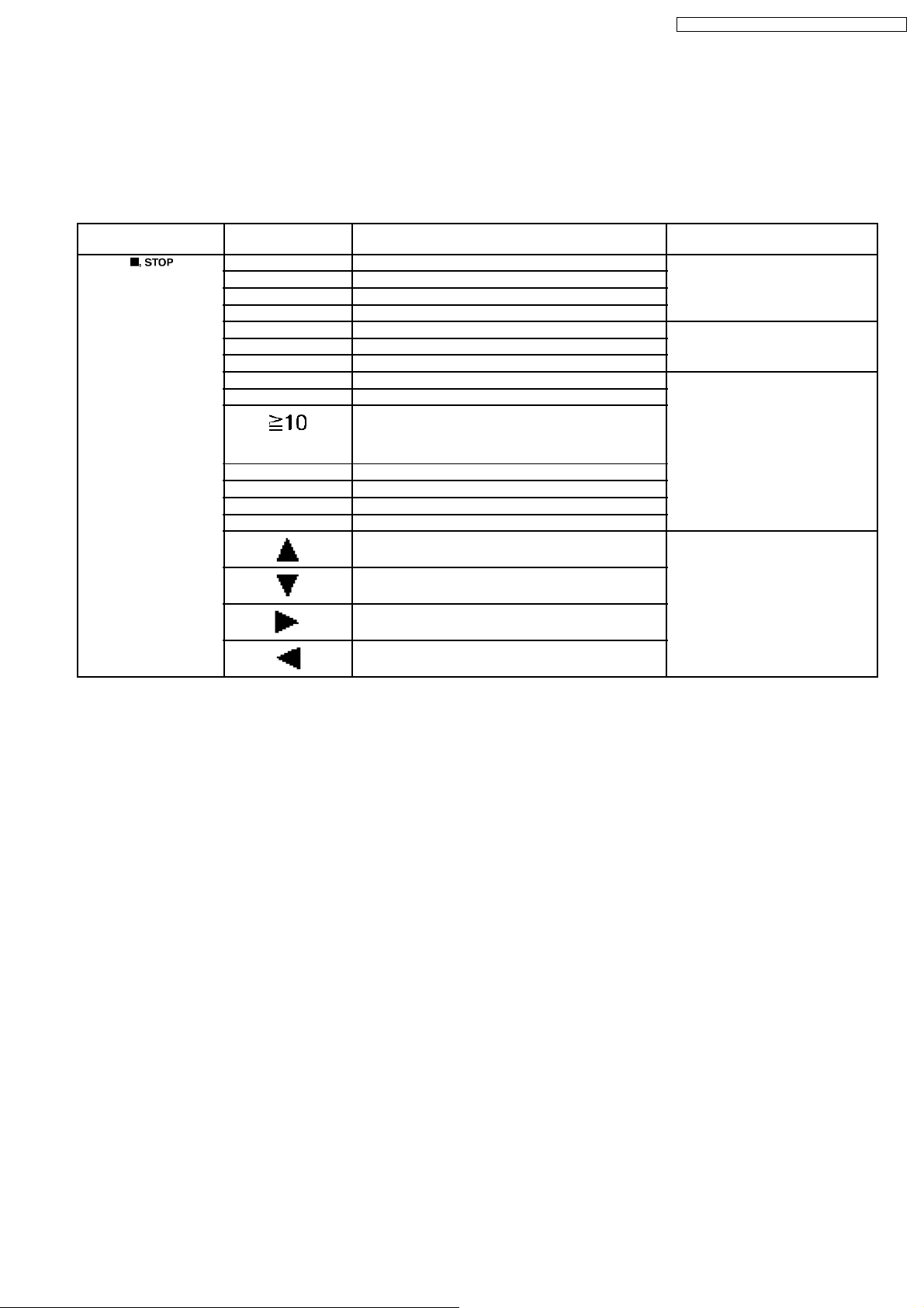
9.2.1. Service Mode Table 1
Item FL Display Key Operation
Mode Name Description Front Key
Jitter check Jitter check.
Jitter rate is measured and displayed.
Measurement is repeatedly done in
the cycle of one second. Read error
counter starts from zero upon mode
setting. When target block data failed
to be read out, the counter advances
by one increment. When the failure is
caused by minor error, it may be
corrected when retired to enable
successful reading. In this case, the
counter advances by one. When the
error persists even after retry, the
counter may jump by two or more.
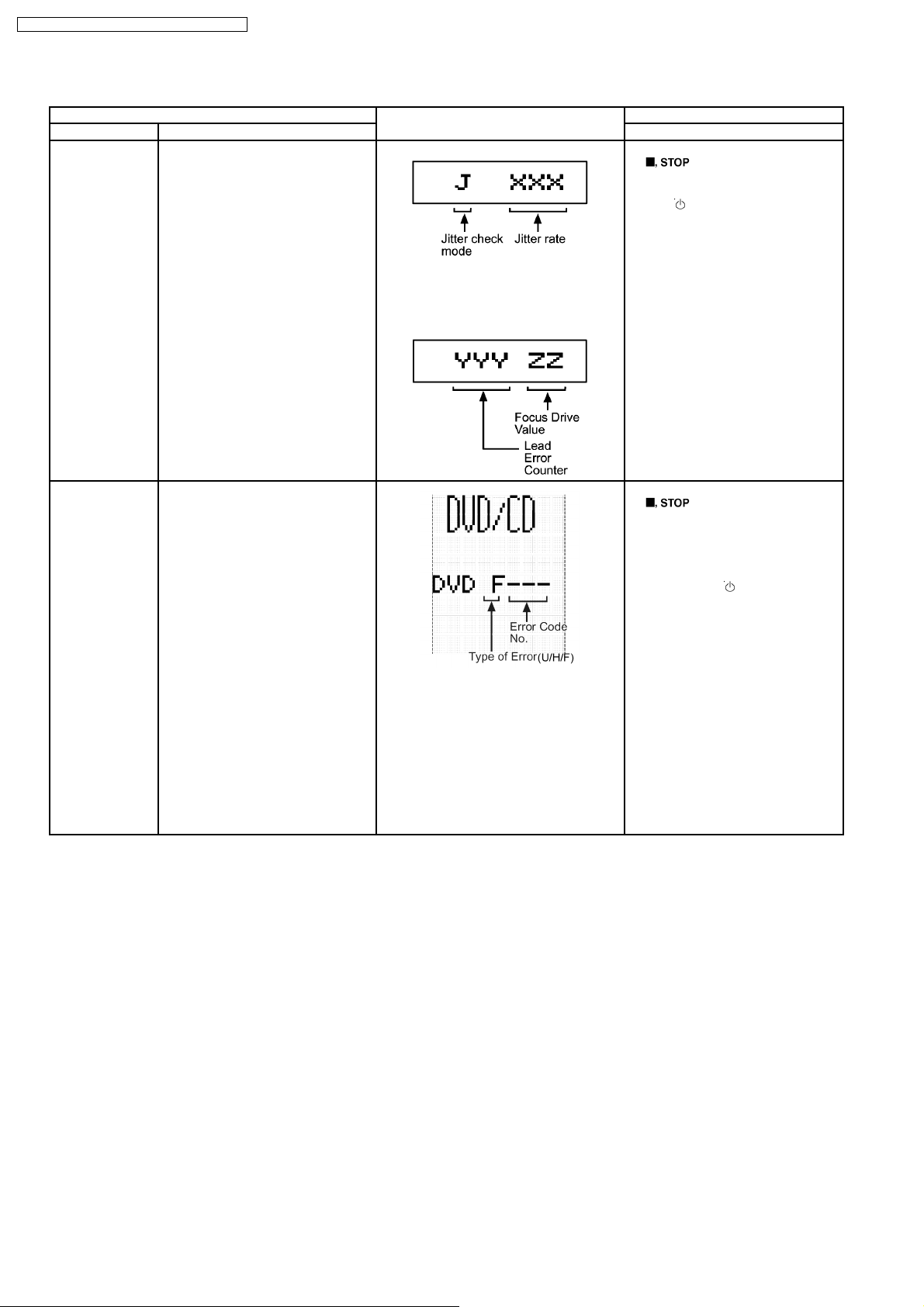
FL Display sequence
Display 1 → 2
(Display 1)
Jitter rate is shown in decimal notation to
one place of decimal.
Focus drive value is shown in hexadecimal
notation.
(Display 2)
In STOP (no disc) mode, press
[
and [5] button on the remote control
unit.
Press [
] button on the main unit,
] button to exit.
Error code check Error code check.
The latest error code stored in the
EEPROM IC is displayed.
Note: Refer to “Section 9.3 DVD Self
Diagnostic Function Error Code” for
more details information on the error
codes.
Error code (play_err) is expressed in the
following convention.
Error code = 0 x DAXX is expressed: →
DVDnn U12
Error code = 0 x DBXX is expressed: →
DVDnn H12
Error code = 0 x DXXX is expressed: →
DVDnn F123
Error code = 0 x 0000 is expressed: →
DVDnn F--* “xx” denotes the error code
In STOP (no disc) mode, press
[
and [0] button on the remote control
unit. *With pointing of cursor up and
down on display.
Cancelled automatically 5 seconds
later.
To exit, press [
unit or remote control.
] button on the main unit,
] button on main
28
SA-NC9GC / SA-NC9GS / SA-NC9GCS / SA-NC9GN
Item FL Display Key Operation
Mode Name Description Front Key
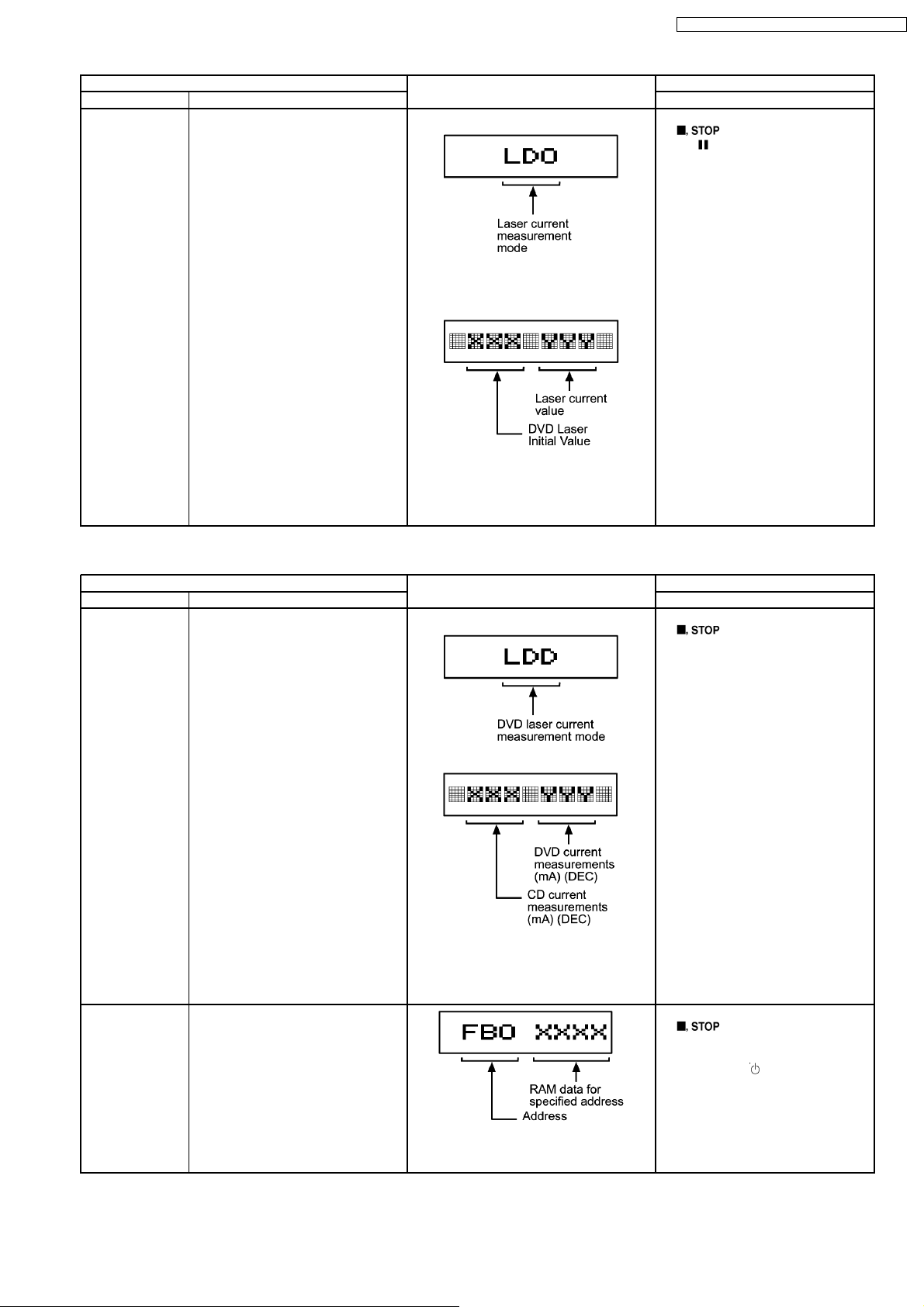
Initial setting of
laser drive current
Initial setting of laser drive current.
Initial current value for the DVD laser
and CD laser is separately saved in
the EEPROM IC.
FL Display sequence
Display 1 → 2
1. (Display 1)
The measurement value in decimal
notation
2. (Display 2)
The value denotes the current in decimal
notation. The above example shows the
initial current XXXmA and YYYmA for DVD
laser and CD laser respectively when the
laser is switched on.
In STOP (no disc) mode, press
[
and [
remote control unit.
Cancelled automatically 5 seconds
later.
] button on the main unit,
, PAUSE] button on the
9.2.2. Service Mode Table 2
Item FL Display Key Operation
Mode Name Description Front Key
DVD laser drive
current
measurement
ADSC internal
RAM data check
DVD laser drive current
measurement.
DVD laser drive current is measured
and the result is displayed together
with the initial value stored in the
EEPROM IC.
After the measurement, DVD laser
emission is kept on. It is turned off
when POWER key is switched off.
FL Display sequence
Display 1 → 2
ADSC internal RAM data check.
ADSC internal RAM data is read out
and displayed.
1. (Display 1)
2. (Display 2)
The value denotes the current in decimal
notation.
The above example shows the initial
current is XXXmA & YYYmA for the
measured value.
In STOP (no disc) mode, press
[
and [FUNCTIONS] button on the
remote control unit.
Cancelled automatically 5 seconds
later.
In STOP (no disc) mode, press
[
and [1] button on the remote control
unit.
To exit, press [
] button on the main unit,
] button on the main unit,
] button.
The value is shown in hexadecimal notation.
The above example shows the data in
ADSC address FBOh is XXXXh.
29
SA-NC9GC / SA-NC9GS / SA-NC9GCS / SA-NC9GN
Item FL Display Key Operation
Mode Name Description Front Key
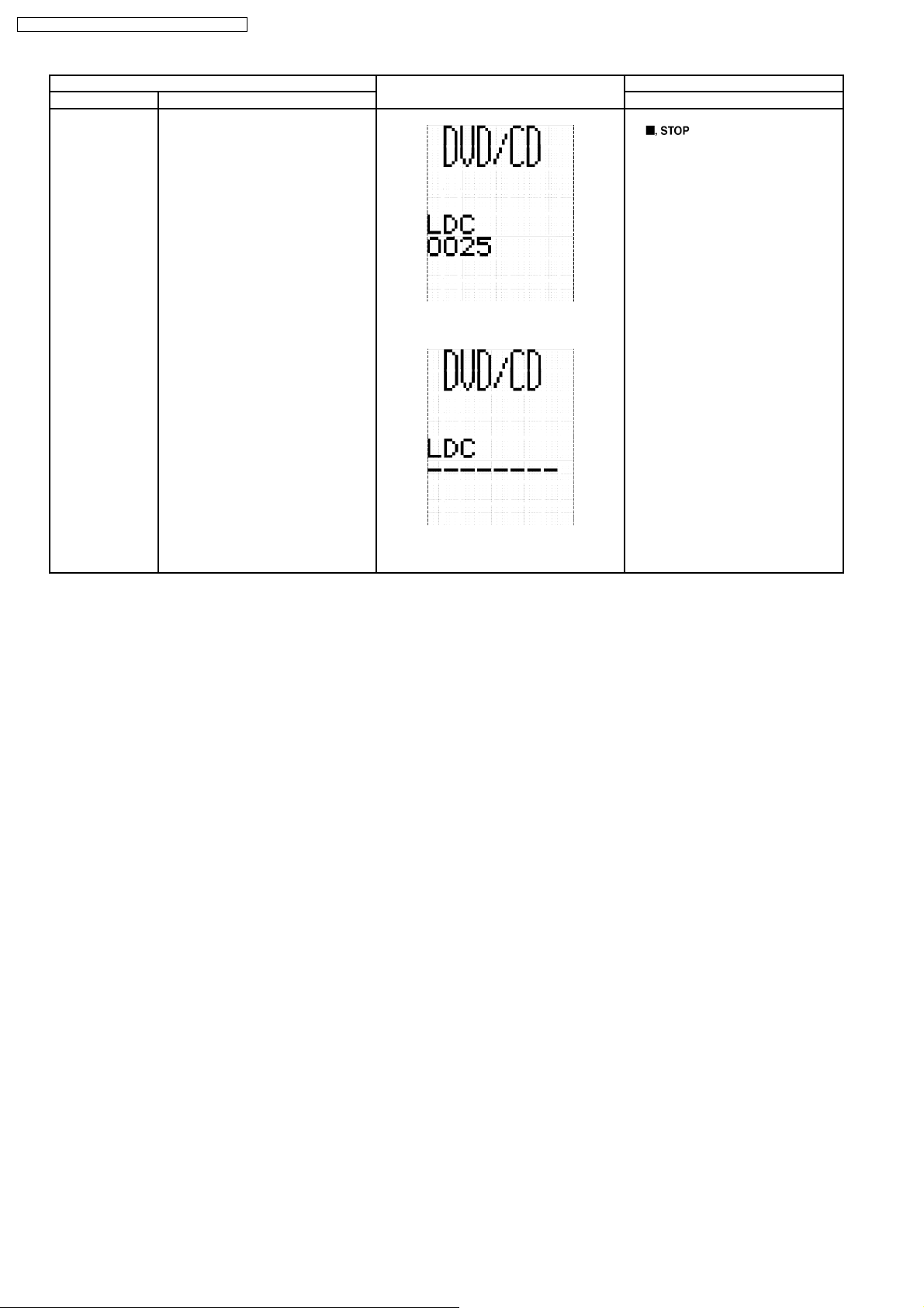
CD laser drive
current
measurement
CD laser drive current measurement.
CD laser drive current is measured
and the result is displayed together
with the initial value stored in the
EEPROM IC.
After the measurement, CD laser
emission is kept on. It is turned off
when POWER key is switched off.
FL Display sequence
Display 1 → 2
(Display 1)
The value denotes the current in decimal
notation.
(Display 2)
In STOP (no disc) mode, press
[
] button on the main unit,
and [3] button on the remote control
unit.
Cancelled automatically 5 seconds
later.
The above example shows the initial current
is 0XXmA and the measured value is
0YYmA.
30
 Loading...