

Panasonic SAHT-680-PL Service manual
A
ORDER NO. MD0502028C3
DVD Home Theater Sound System
SA-HT680PL
Colour
(S).......................Silver Type
Specifications
lGeneral
Power Source:
Power consumption: 280 W
Dimensions (W×H×D): 430×105×381 mm
Mass: 7.1 kg
lAmplifier section
RMS Output Power: Dolby Digital Mode
lTotal RMS Dolby Digital
mode Power:
At 1kHz and total harmonic of 10%
lFront:
lCenter:
lSurround:
At 100Hz and total harmonic of 10%
lActive subwoofers:
FTC Output Power: Dolby Digital Mode:
lTotal FTC Dolby Digital mode Power:
At 120Hz-20kHz and total harmonic of 1%
lFront:
lCenter:
lSurround:
At 45Hz-120Hz and total harmonic of 1%
lSubwoofer:
C 120V, 60Hz
600 W
55 W/ Channel (6Ω)
160 W/ Channel (6Ω)
55 W/ Channel (6Ω)
220 W/ Channel (4Ω)
390 W
35 W/ Channel (6Ω)
110 W/ Channel (6Ω)
35 W/ Channel (6Ω)
140 W/ Channel (4Ω)
lFM tuner section
Frequency Range: 87.9-107.9MHz
(200kHz in step)
87.5-108.0MHz
(100kHz in step)
Sensitivity: 2.5µV (IHF)
S/N 26dB 2.2µV
Antenna Terminal: 75Ω (non balance)
lAM tuner section
Frequency Range: 520-1710kHz (10kHz in step)
AM Sensitivity S/N 20dB at
1000kHz:
Phone Jack:
Terminal: Stereo 3.5mm jack
lDisc section
Discs played [8 cm or 12 cm]:
(1) DVD-RAM (DVD-VR compatible, JPEG formatted discs)
(2) DVD-Audio
(3) DVD-Video
(4) DVD-R, DVD-RW (DVD-Video compatible)
+R, +RW (Video compatible)
(5) CD-Audio (CD-DA)
(6) Video CD
(7) SVCD (Conforming to IEC62107)
560µV/m
© 2005 Panasonic AVC Networks Singapore Pte.
Ltd. All rights reserved. Unauthorized copying and
distribution is a violation of law.
V
Y
Y
SA-HT680PL
(8) CD-R/CD-RW (CD-DA, Video-CD, SVCD, MP3, WMA, JPEG
formatted discs)
(9) MP3/WMA
lCompatible compression rate:
MP3: between 32 kbps and 320 kbps
WMA: between 48 kbps and 320 kbps
lMaximum number of recognizable audio and picture contents
and groups:
4000 audio and picture
contents and 400 groups
(10) JPEG
lExif Ver 2.1 JPEG Baseline files
lPicture resolution: between 320 x 240 and 6144 x 4096
pixels (sub sampling is 4:2:2 or 4:2:0)
lMaximum number of recognizable audio and picture contents
and groups:
4000 audio and picture
contents and 400 groups
(11) HighMAT Level 2 (Audio and lmage)
Pick up:
Source of light beam: Semiconductor Laser
Wavelength:
lCD:
lDVD:
Audio output (DISC):
Number of channels: 5.1 ch (FL, FR, C, SL, SR,
lVideo section
ideo system:
Signal system: NTSC
Composite video output:
Output level: 1 Vp-p (75 Ω)
Terminal: Pin jack (1 system)
S-video output:
output level: 1 Vp-p (75 Ω)
C output level:
Terminal S terminal (1 system)
Component video output (480P/480I):
output level: 1 Vp-p (75 Ω)
PBoutput level: 0.7 Vp-p (75 Ω)
PRoutput level: 0.7 Vp-p (75 Ω)
Terminal: Pin jack (Y: green, PB: blue,
Power consumption in standby mode:
785nm
662nm
SW)
NTSC; 0.286 Vp-p (75 Ω)
P
: red) (1 system)
R
approx 0.5W
Note:
1. Specifications are subject to change without notice.
Mass and dimensions are approximate.
2. Total harmonic distortion is measured by the digital spectrum
analyzer.
Solder:
This model uses lead free solder (PbF).
CONTENTS
Page Page
4
1 Safety Precautions
1.1. GENERAL GUIDELINES
2 Prevention of Electro Static Discharge (ESD) to
4
Electrostatically Sensitive (ES) Devices
2
4

SA-HT680PL
3 Before Repair and Adjustment 5
4 Protection Circuitry
5 Precaution of Laser Diode
6 About Lead Free Solder (PbF)
7 General Description
7.1. Operating instructions
7.2. Disc information
7.3. About HighMAT
8 Accessories
9 Handling Precautions for Optical Pickup Unit
14
15
9.1. Cautions to Be Taken in Handling the Optical Pickup Unit
15
9.2. Cautions to Be Taken When Replacing the Optical Pickup
9.3. Grounding for electrostatic breakdown prevention
10 Disassembly Main Component Replacement Procedure
10.1. Disassembly Procedure
10.2. Main Components and P.C.B. Locations
10.3. Disassemble Top Cabinet
10.4. Disassemble Front Panel
10.5. Disassemble CR16D Mechanism Unit
10.6. Disassemble Rear panel
10.7. Disassemble Main P.C.B.
10.8. Disassemble of Regulator P.C.B.
10.9. Disassemble of AC Inlet P.C.B. & Transformer P.C.B.
10.10. Disas semble of Power P.C.B.
10.11. Disas semble FL P.C.B. & Power Button P.C.B.
11 Assembling and Disassembling the Mechanism unit
11.1. Replacement for DVD traverse deck
11.2. Replacement for optical pickup unit
11.3. Assembling for traverse motor and spindle motor
11.4. Procedure for removing CR16D mechanism unit
11.5. CR16 mechanism disassembly procedure
11.6. CR16 mechanism assembly procedure
11.7. Disassembly for traverse mechanism
12 Service Position
12.1. Checking & Repair AC Inlet P.C.B
12.2. Checking & Repair FL P.C.B and Power BTN P.C.B.
15
15
17
17
18
19
19
19
20
20
20
20
21
21
22
22
22
25
27
27
33
45
47
47
47
12.3. Checking & Repair Main P.C.B., Power P.C.B, Regulator
P.C.B.
12.4. Checking & Repair DVD Module P.C.B.
47
47
13 Optical Pick-up Self-Diagnosis and Replacement Procedure
5
6
6
7
7
8
9
13.1. Optical Pickup Breakdown Diagnosis
13.2. Service Mode Table 1
13.3. DVD Self Diagnostic Function-Error Code
13.4. Service mode table 2
13.5. Sales demonstration lock function
13.6. Handling After Completing Repairs
14 Self-Diagnosis Function
14.1. Automatic Displayed Error Codes
14.2. Memorized Error Codes
15 Service Precautions
15.1. Recovery after the DVD player is repaired
15.2. Firmware version-up of the DVD player
16 Adjustment Procedure
16.1. Service Tools and Equipment
16.2. Important points in adjustment
16.3. Storing and handling of test discs
16.4. Optical adjustment
17 Abbreviations
18 Voltage Chart
18.1. DVD Module P.C.B.
18.2. Main P.C.B.
18.3. CD Loading P.C.B. & AC Inlet P.C.B. & Regulator P.C.B.
18.4. FL P.C.B.
18.5. Power P.C.B.
19 Wave Form Chart
20 Schematic Diagram Notes
21 Block Diagram
22 Schematic Diagram
23 Printed Circuit Board Diagram
24 Wiring Connection Diagram
25 Illustration of IC 痴, Transistors and Diodes
26 Terminal Function of ICs
26.1. IC2018 (C2CBJG000578): Operation CPU
27 Parts Location and Replacement Parts List
27.1. Loading Mechanism, Traverse Unit & Cabinet
27.2. Component Parts List
27.3. Packing Materials & Accessories Parts List
27.4. Packaging
28 Schematic Diagram for printing with letter size
48
48
49
49
51
53
53
54
54
54
55
55
55
56
56
56
56
57
59
61
61
62
63
63
63
64
65
67
73
83
89
91
92
92
93
94
102
111
112
113
3
SA-HT680PL
1 Safety Precautions
1.1. GENERAL GUIDELINES
1. When servicing, observe the original lead dress. If a short circuit is found, replace all parts which have been overheated or
damaged by the short circuit.
2. After servicing, see to it that all the protective devices such as insulation barriers, insulation papers shields are properly
installed.
3. After servicing, make the following leakage current checks to prevent the customer from being exposed to shock hazards.
1.1.1. LEAKAGE CURRENT COLD
CHECK
1. Unplug the AC cord and connect a jumper between the two
prongs on the plug.
2. Measure the resistance value, with an ohmmeter, between
the jumpered AC plug and each exposed metallic cabinet
part on the equipment such as screwheads, connectors,
control shafts, etc. When the exposed metallic part has a
return path to the chassis, the reading should be between
1MΩ and 5.2MΩ.
When the exposed metal does not have a return path to
the chassis, the reading must be
Figure 1
.
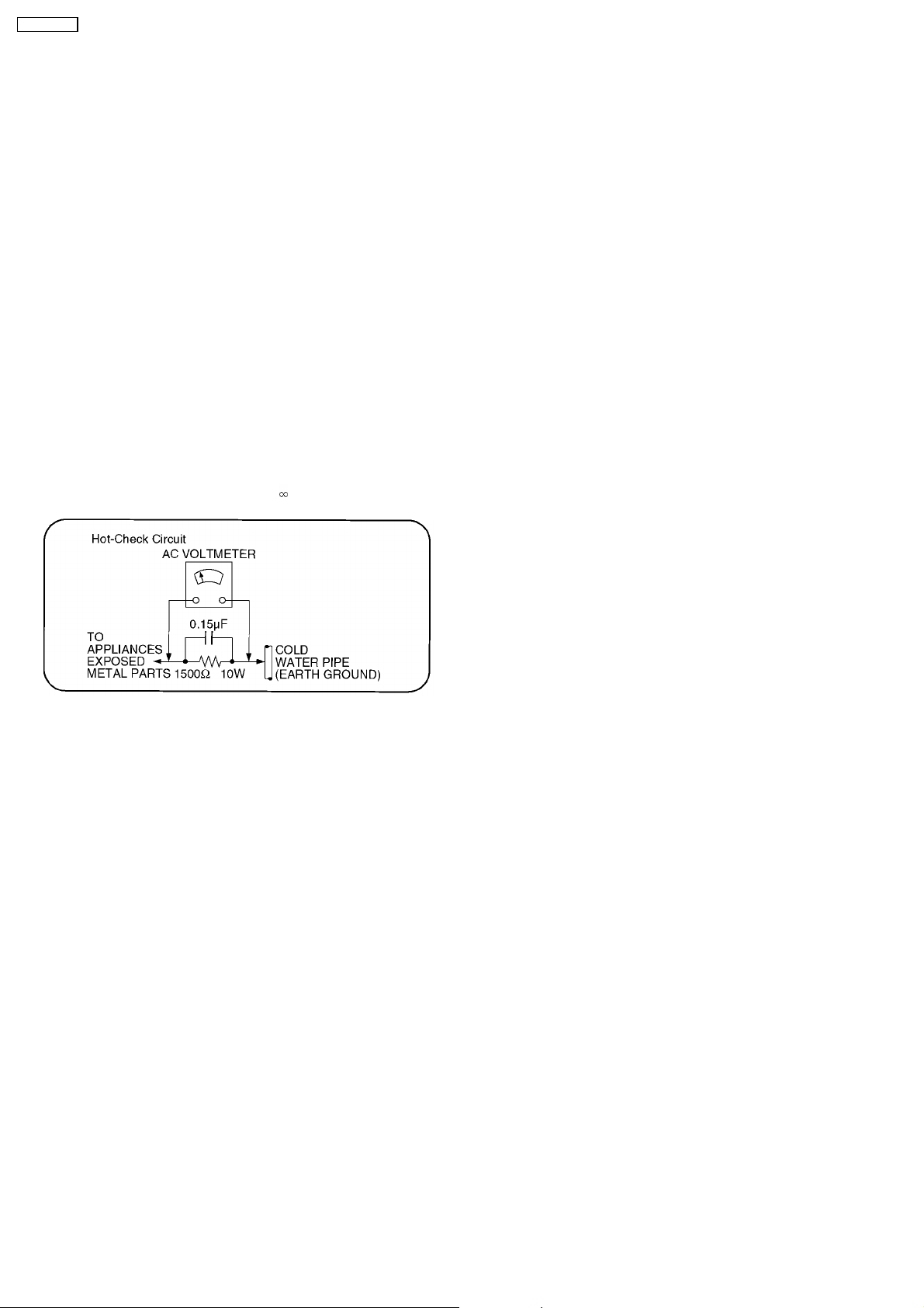
1.1.2. LEAKAGE CURRENT HOT CHECK
(See Figure 1 .)
1. Plug the AC cord directly into the AC outlet. Do not use an
isolation transformer for this check.
2. Connect a 1.5kΩ, 10 watts resistor, in parallel with a 0.15µF
capacitors, between each exposed metallic part on the set
and a good earth ground such as a water pipe, as shown in
Figure 1.
3. Use an AC voltmeter, with 1000 ohms/volt or more
sensitivity, to measure the potential across the resistor.
4. Check each exposed metallic part, and measure the
voltage at each point.
5. Reverse the AC plug in the AC outlet and repeat each of the
above measurements.
6. The potential at any point should not exceed 0.75 volts
RMS. A leakage current tester (Simpson Model 229 or
equivalent) may be used to make the hot checks, leakage
current must not exceed 1/2 milliamp. In case a
measurement is outside of the limits specified, there is a
possibility of a shock hazard, and the equipment should be
repaired and rechecked before it is returned to the
customer.
2 Prevention of Electro Static Discharge (ESD) to
Electrostatically Sensitive (ES) Devices
Some semiconductor (solid state) devices can be damaged easily by static electricity. Such components commonly are called
Electrostatically Sensitive (ES) Devices. Examples of typical ES devices are integrated circuits and some field-effect transistors and
semiconductor "chip" components. The following techniques should be used to help reduce the incidence of component damage
caused by electro static discharge (ESD).
1. Immediately before handling any semiconductor component or semiconductor-equipped assembly, drain off any ESD on your
body by touching a known earth ground. Alternatively, obtain and wear a commercially available discharging ESD wrist strap,
which should be removed for potential shock reasons prior to applying power to the unit under test.
2. After removing an electrical assembly equipped with ES devices, place the assembly on a conductive surface such as
aluminum foil, to prevent electrostatic charge buildup or exposure of the assembly.
3. Use only a grounded-tip soldering iron to solder or unsolder ES devices.
4. Use only an anti-static solder removal device. Some solder removal devices not classified as "anti-static (ESD protected)" can
generate electrical charge sufficient to damage ES devices.
5. Do not use freon-propelled chemicals. These can generate electrical charges sufficient to damage ES devices.
6. Do not remove a replacement ES device from its protective package until immediately before you are ready to install it. (Most
replacement ES devices are packaged with leads electrically shorted together by conductive foam, aluminum foil or comparable
conductive material).
7. Immediately before removing the protective material from the leads of a replacement ES device, touch the protective material
to the chassis or circuit assembly into which the device will be installed.
4

SA-HT680PL
Caution
Be sure no power is applied to the chassis or circuit, and observe all other safety precautions.
8. Minimize bodily motions when handling unpackaged replacement ES devices. (Otherwise harmless motion such as the
brushing together of your clothes fabric or the lifting of your foot from a carpeted floor can generate static electricity (ESD)
sufficient to damage an ES device).
3 Before Repair and Adjustment
Disconnect AC power, discharge Power Supply Capacitors C546~C549 through a 10 Ω, 10 W resistor to ground.
DO NOT SHORT-CIRCUIT DIRECTLY (with a screwdriver blade, for instance), as this may destroy solid state devices.
After repairs are completed, restore power gradually using a variac, to avoid overcurrent.
Current consumption at AC 120 V, 60 Hz in NO SIGNAL mode should be ~ 650 mA.
4 Protection Circuitry
The protection circuitry may have operated if either of the following conditions are noticed:
· No sound is heard when the power is turned on.
· Sound stops during a performance.
The function of this circuitry is to prevent circuitry damage if, for example, the positive and negative speaker connection wires are
“shorted”, or if speaker systems with an impedance less than the indicated rated impedance of the amplifier are used.
If this occurs, follow the procedure outlines below:
1. Turn off the power.
2. Determine the cause of the problem and correct it.
3. Turn on the power once again after one minute.
Note:
When the protection circuitry functions, the unit will not operate unless the power is first turned off and then on again.
5
SA-HT680PL
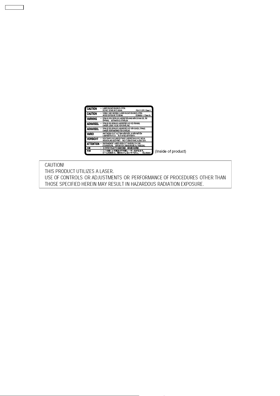
5 Precaution of Laser Diode
CAUTION :
This product utilizers a class 1 laser. Invisible laser radiation is emitted from the optical pick up lens.
When the unit is turned on:
Wavelength : 662nm/(DVD)785nm(CD)
Maximum output radiation power from pick up : 100µW/VD E
Laser radiation from pick up unit is safety level, but be sure the followings:
1. Do not disassemble the optical pick up unit, since radiation from exposed laser diode is dangerous.
2. Do not adjust the variable resistor on the pick up unit. It was already adjusted.
3. Do not look at the focus lens using optical instruments.
4. Recommend not to look at pick up lens for a long time.
6 About Lead Free Solder (PbF)
Distinction of PbF PCB: PCBs (manufactured) using lead free solder will have a Pbf stamp on the PCB.
Caution:
· Pb free solder has a higher melting point than standard solder; Typically the melting point is 50 - 70°F (30 - 40°C) higher.
Please use a high temperature soldering iron. In case of the soldering iron with temperature control, please set it to 700 ±
20°F (370 ± 10°C).
· Pb free solder will tend to splash when heated too high (about 1100°F/ 600°C).
When soldering or unsoldering, please completely remove all of the solder on the pins or solder area, and be sure to heat the
soldering points with the Pb free solder until it melts enough.
6
7 General Description
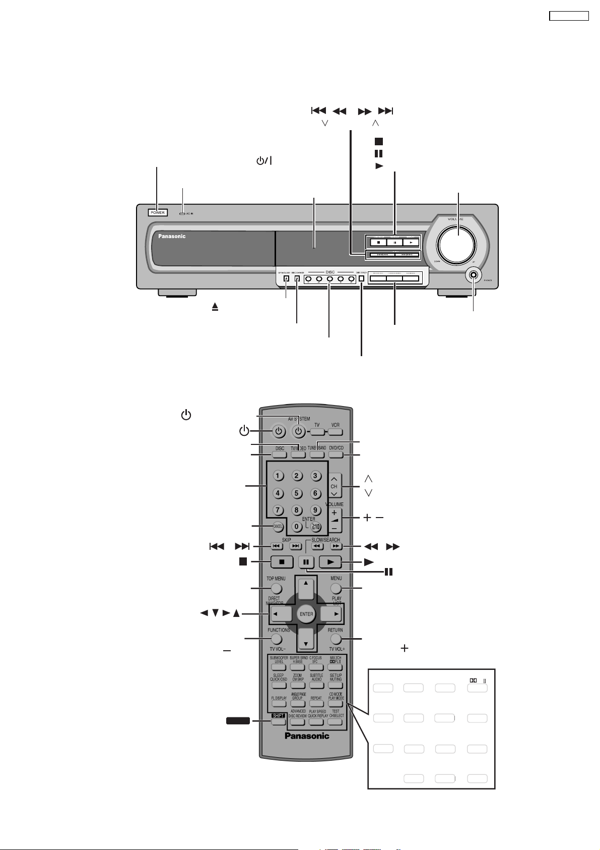
7.1. Operating instructions
Standby/on switch [POWER,
AC suppy indicator [AC IN]
OPEN/CLOSE
DISC CHANGE
Disc buttons/ indicators
SA-HT680PL
//
,
TUNING
TUNE MODE
/
/
]
Display
FM MODE
MEMORY
/
VOLUME
PHONES
SELECTOR
PROGRESSIVE
DISC CHECK
CD MODE
/AV
SYSTEM
TV/VIDEO
DISC
Numbered
buttons
CANCEL
,
TOP MENU
ENTER
FUNCTIONS/
TV VOL
SHIFT
TUNER/BAND
DVD/CD
CH
CH
VOLUME
,
MENU
RETURN/
TV VOL
SUBW SUPER SRND
OOFER
LEVEL
H.BASS
SLEEP
QUICK OSD
FL DISPLAY
ZOOM
CM SKIP
ANGLE / PAGE
GROUP
C.FOCUS
SFC
SUBTITLE
AUDI O
REPEAT
MIX 2CH
PL
SETUP
MUTING
CD MODE
PLAY MODE
ADVANCED PLAY SPPED TEST
DISC REVIEW
7
QUICK REPLAY CH SELECT
L
o
v
e
A
l
b
um
L
o
v
e
A
l
b
u
m
M
i
c
r
o
s
c
o
p
i
c
SA-HT680PL
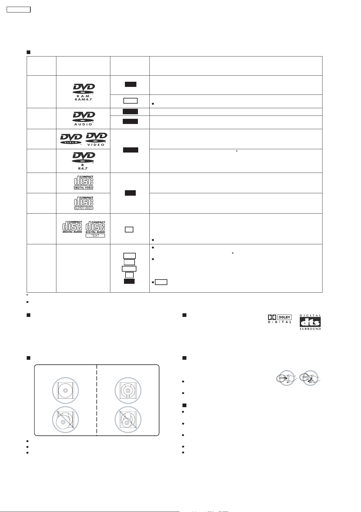
7.2. Disc information
Discs that can be played
Disc Logo
DVD-RAM
DVD-Audio
DVD-Video
Indication in
these operating
instructions
RAM
JPEG
DVD-A
DVD-V
Remarks
Recorded with devices using Version 1.1 of the Video Recording Format (a unified
video recording standard), such as DVD video recorders, DVD video cameras,
personal computers, etc.
Recorded using the DCF (Design rule for Camera File system) standard Vesion 1.0.
To play JPEG files, select “Play as Data Disc” in Other Menu.
—
Some DVD-Audio discs contain DVD-Video content.
To play DVD-Video content, select “Play as DVD-Video” in Other Menu.
—
DVD-V
DVD-R
Panasonic DVD-R recorded and finalized on Panasonic DVD-Video recorders or
DVD-Video cameras are played as DVD-Video on this unit.
—
Video CD
VCD
Conforming to IEC62107
SVCD
This unit is compatible with HDCD, but does not support the Peak Extend function
(a function which expands the dynamic range of high level signals).
CD
CD
HDCD-encoded CD’s sound better because they are encoded with 20 bits, as
compared with 16 bits for all other CD’s.
During HDCD play, “HDCD” lights on the unit’s display.
This unit can play CD-R/RW (audio recording disc) recorded with the formats on
the left. Close the sessions or finalize the disc after recording.
HighMAT discs
WMA, MP3 or JPEG files only.
To play without using the HighMAT function, select “Play as Data Disc” in Other
Menu.
WMA
This unit is not compatible with Multiple Bit Rate (MBR: a file that contains
CD-R
CD-RW
WMA
MP3
—
JPEG
CD
VCD
the same content encoded at several different bit rates).
A process that allows play on compatible equipment.
It may not be possible to play the above discs in all cases due to the type of disc or condition of the recording.
Discs that cannot be played
DVD-ROM, CD-ROM, CDV, CD-G, DVD+R, +RW , DVD-RW, SACD,
DivX Video Discs and Photo CD, DVD-RAM that cannot be removed
Audio format of DVD’s
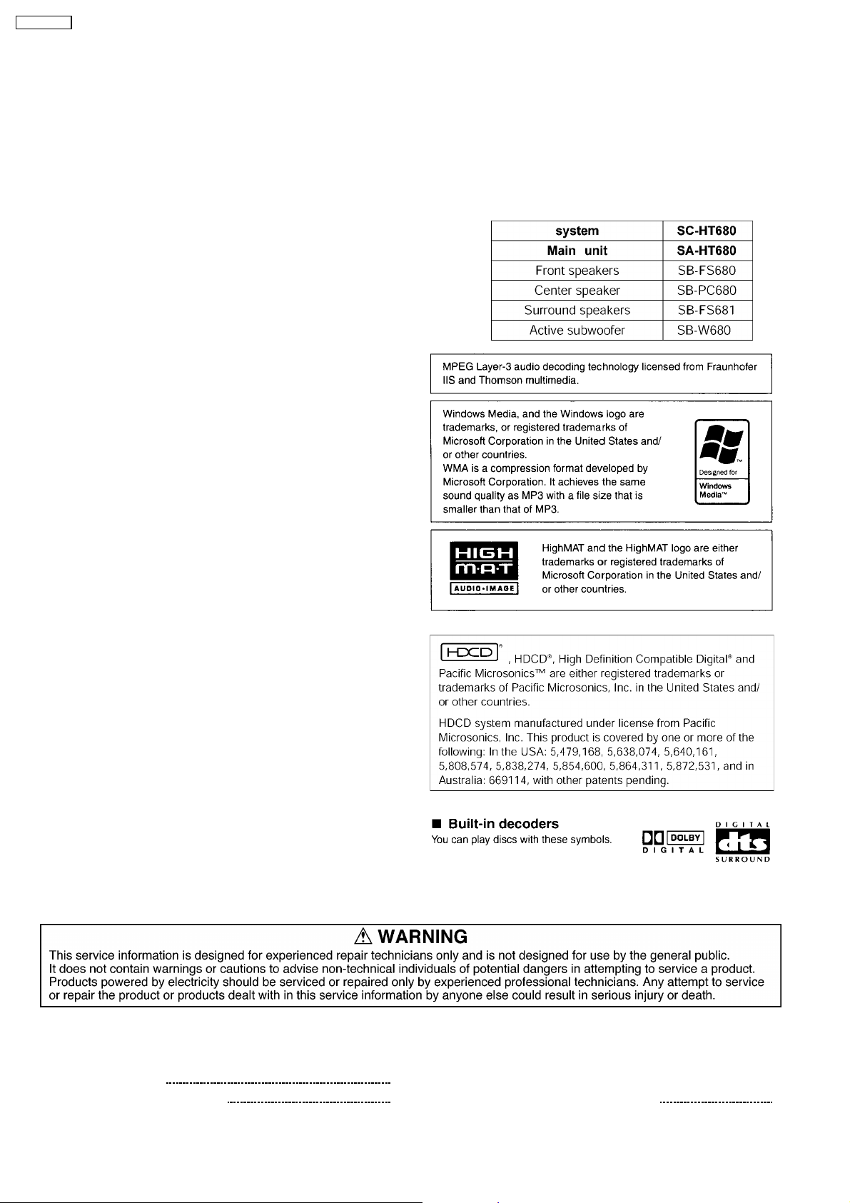
This unit automatically recognizes and
decodes discs with these symbols.
from their cartridge, 2.6-GB and 5.2-GB DVD-RAM, and “Chaoji
VCD” available on the market including CVD, DVCD and SVCD that
do not conform to IEC62107.
Inserting a disc correctly
To clean disc
DVD-Audio, DVD-Video, Video CD, SVCD and CD
12 cm
Microscopic
Love Album
Neil Ruby's
Sundae GirlGreatest Hits
8 cm
Microscopic
Including
Love Album
Sundae Girl
Greatest Hits
Including
Neil Ruby's
Wipe with a damp cloth and then wipe dry.
DVD-RAM and DVD-R
Clean with an optional DVD-RAM/PD disc
cleaner (LF-K200DCA1, where available).
Never use cloths or cleaners for CD’s, etc.
Disc handling precautions
N
e
G
i
l
r
M
e
R
a
t
u
L
e
i
b
s
c
o
t
y
r
v
'
o
H
s
e
s
i
c
t
A
s
o
p
l
b
i
c
um
I
S
n
u
c
l
n
u
d
d
a
i
n
e
g
G
i
r
l
S
u
M
n
I
d
n
L
a
i
e
c
c
o
lu
r
G
v
d
o
i
r
i
e
n
s
l
g
c
A
o
p
l
b
i
c
u
m
G
r
e
Ne
a
te
i
s
l
t
R
H
u
it
b
s
y
'
s
Insert the disc correctly into position as indicated in the diagrams above.
Place only one disc on a tray.
Insert the disc with the label side facing up.
Do not attach labels or stickers to discs (This may cause disc
warping, rendering it unusable).
Do not write on the label side with a ball-point pen or other writing
instrument.
Do not use record cleaning sprays, benzine, thinner, static
electricity prevention liquids or any other solvent.
Do not use scratch-proof protectors or covers.
Do not use the following discs:
– Discs with exposed adhesive from removed stickers or labels
(rented discs, etc).
– Discs that are badly warped or cracked.
– Irregularly shaped discs, such as heart shapes.
8
SA-HT680PL
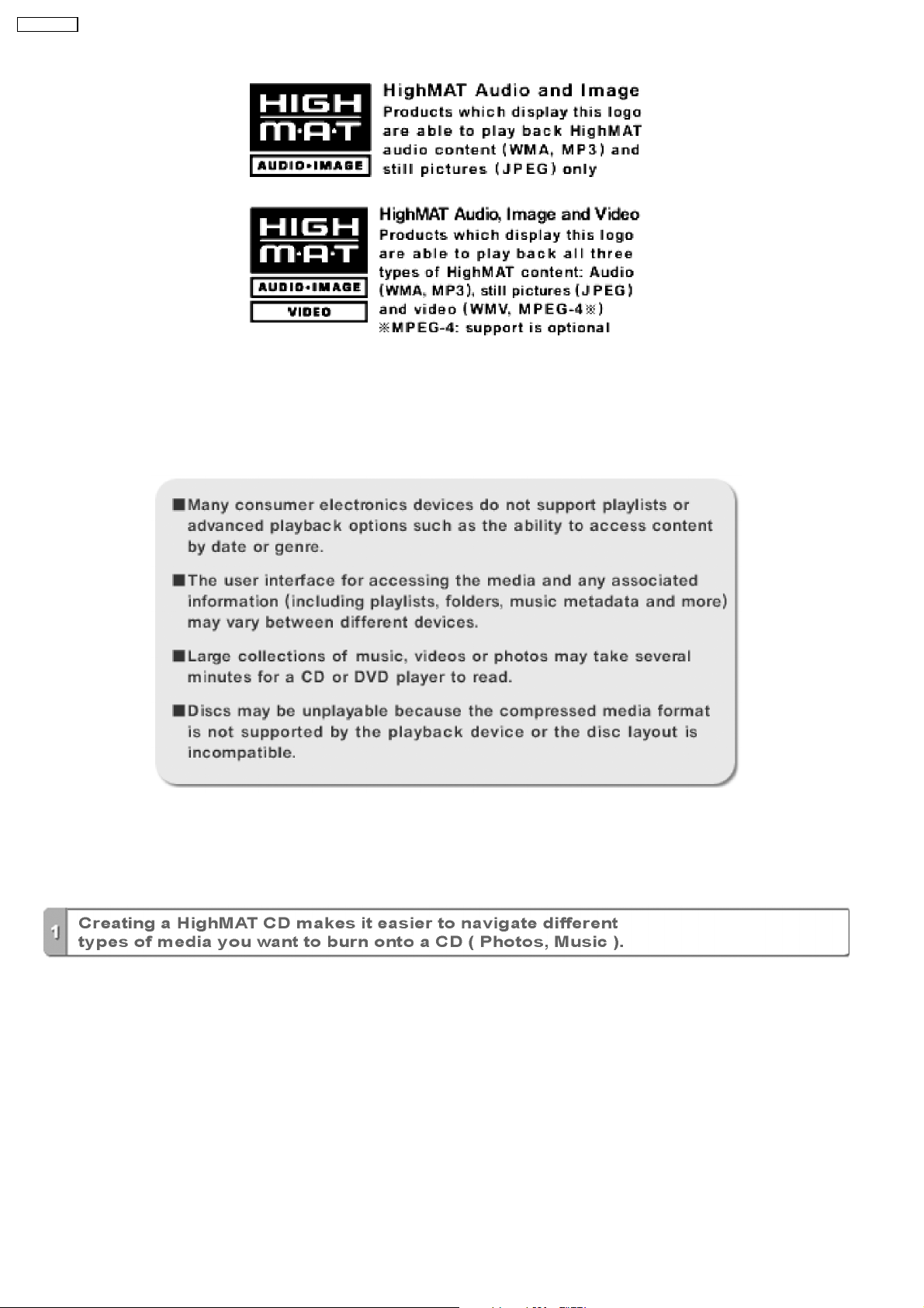
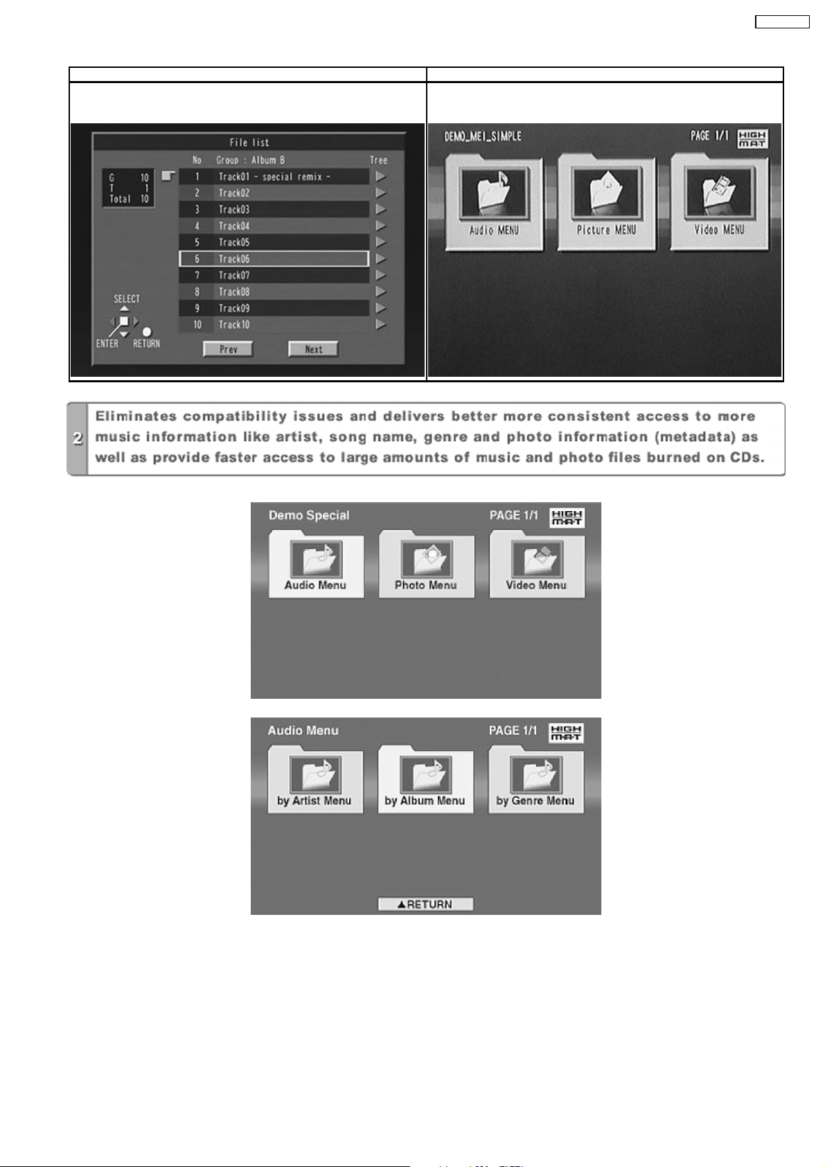
7.3. About HighMAT
7.3.1. What’s HighMAT?
Consumers worldwide are using PCs to create their own collections of music, photos and even video by burning them onto CDs.
But how these collections can be experienced across different devices can be confusing to navigate, time consuming to access for
a DVD player, and be incomplete in terms of music information available to the customer.
HighMAT offers a solution to this growing consumer problem. HighMAT dramatically improves the digital media experience on
consumer electronic devices by delivering a simple, standardized approach that allows consumers who have created personal
collections of digital music, photography and video on their PC to:
>> Create a HighMAT CD or DVD which can be easily played back on consumer electronics devices such as CD and DVD players,
and car stereos.
>> Move digital media files (using recordable media such as CD-R and CD-RW) between the PC and various playback devices
such as CD and DVD players.
A new standard for creating personal media on consumer electronic devices, HighMAT enable easier and more seamless
interoperability between Windows PCs and devices designed for your living room, or the car.
9
SA-HT680PL
7.3.2. Why take advantage of HighMAT?
A Problem Defined:Today, when consumers create their own digital audio, video or photo collections on CD-R or other physical
formats, there are numerous, inconsistent ways that devices read the data. For the consumer, the playback experience can be
confusing:
A Solution Created: HighMAT delivers a better digital media access experience by creating a standard approach for PCs to
structure digital media on various physical formats and for playback devices to read the data.
7.3.3. Benefits of HighMAT?
10
Conventional HighMAT
Even though DVD player is CD-R/RW compatible, the inconsistent ways
that various DVD players can read the music or photos files often leads
to a confusing and inconsistant playba ck experince.
SA-HT680PL
HighMAT compatible products play content back with consistent
interface. This includes products which are JPEG compatible products
without HighMAT support.
11
SA-HT680PL
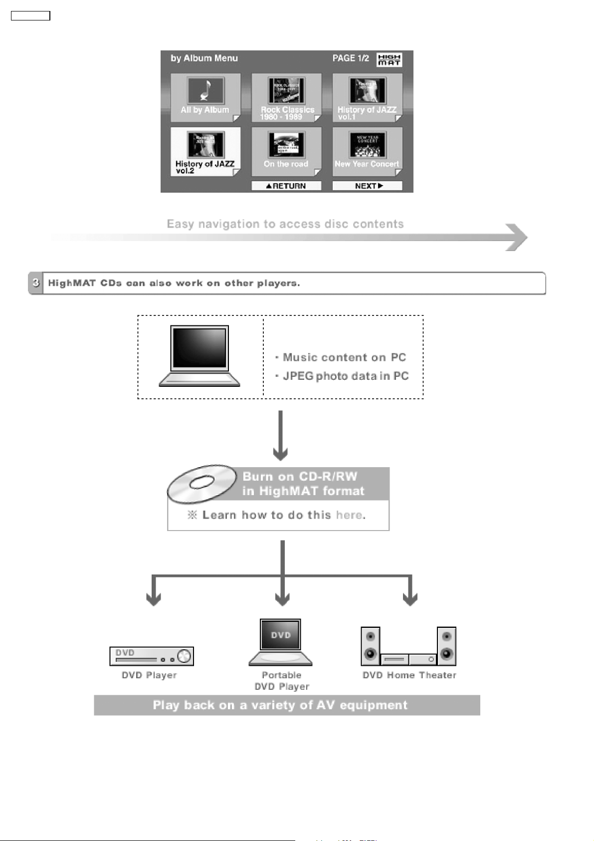
HighMAT is now available for CD Burning and in leading DVD Players.
HighMAT is a new technology that is now available in leading software and consumer electronic devices to dramatically improve
the digital media experience when you create homemade CDs
HighMAT delivers a simple, standardized way for PC software and consumer electronics devices to talk to each other and work
better together.
12

SA-HT680PL
When you create your homemade CDs with software that supports HighMAT CD burning, and then play them back on a DVD
player that supports HighMAT, you get better, easier navigation. You get folders you can access with a single click of your DVD
player´s remote control. You can view important information about your music like full song names, artist titles, album names and
genre. And you can get faster startup on your home entertainment device.
To enjoy the benefits of HighMAT, all you need is software that supports HighMAT for CD burning of music or photos, as well as
a home entertainment device like a DVD player that supports HighMAT for playback. Always look for the HighMAT logo on your
software or home entertainment device to ensure it supports the HighMAT experience.
13
SA-HT680PL
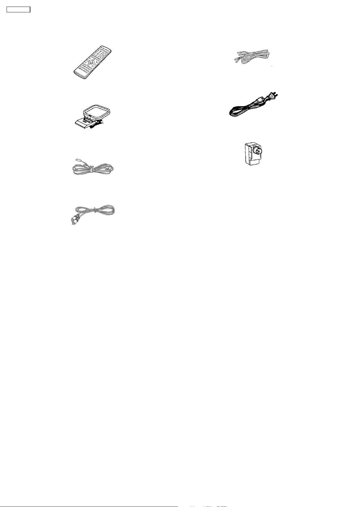
8 Accessories
Speaker cables
Remote control
AC cord
AM loop antenna
Antenna plug
FM indoor antenna
Video Cable
14
SA-HT680PL
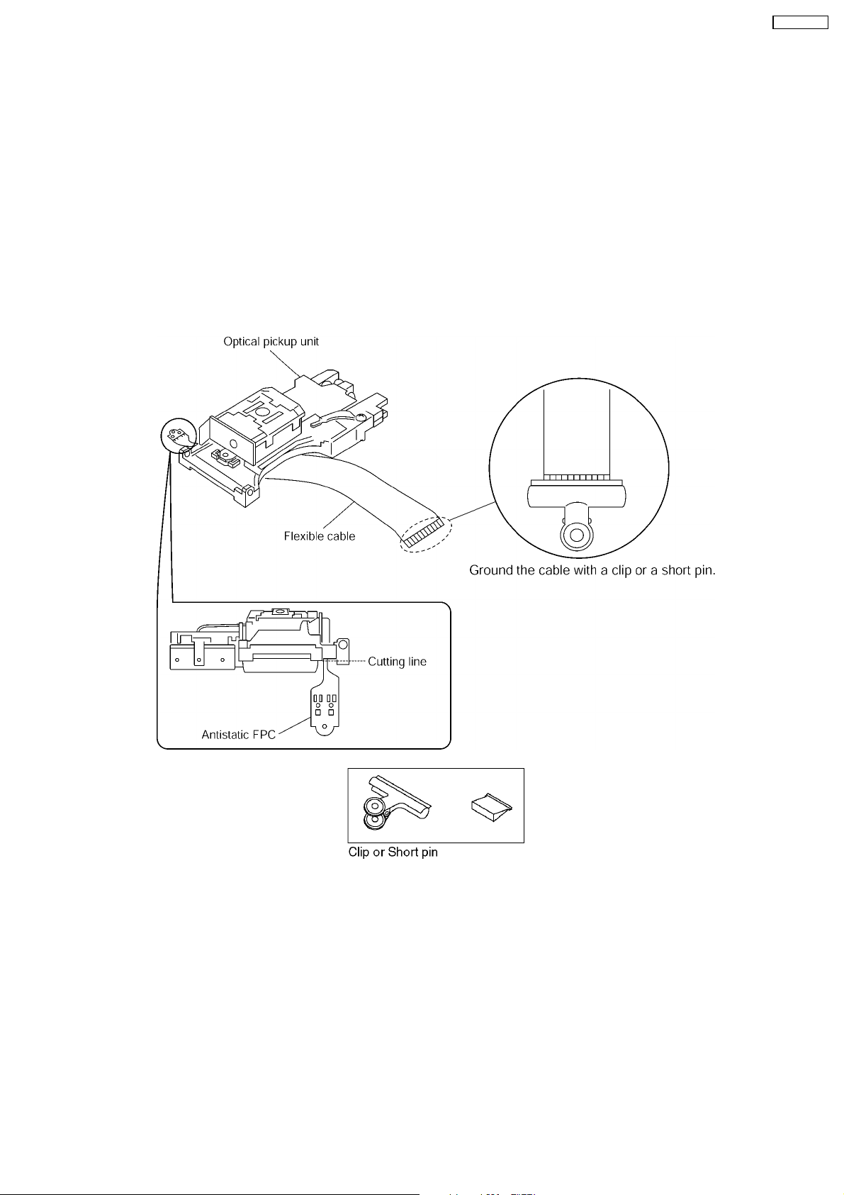
9 Handling Precautions for Optical Pickup Unit
The laser diode in the optical pickup unit may break down due to static electricity of clothes or human body. Special care must be
taken avoid to electrostatic breakdown when servicing and handling the laser diode.
9.1. Cautions to Be Taken in Handling the Optical Pickup Unit
The laser diode in the optical pickup unit may be damaged due to electrostatic discharge generating from clothes or human body.
Special care must be taken avoid to electrostatic discharge damage when servicing the laser diode.
1. Do not give a considerable shock to the optical pickup unit as it has an extremely high-precise structure.
2. To prevent the laser diode from the electrostatic discharge damage, the flexible cable of the optical pickup unit removed from
the PCB should be short-circuited with a short pin or a clip.
3. The flexible cable may be cut off if an excessive force is applied to it. Use caution when handling the flexible cable.
4. The antistatic FPC is connected to the new optical pickup unit. After replacing the optical pickup unit and connecting the flexible
cable, cut off the antistatic FPC.
9.2. Cautions to Be Taken When Replacing the Optical Pickup
The flexible cable of the optical pickup unit which was supplied as a component is equipped with a short clip to prevent the laser
diode from being damaged due to electrostatic discharge. Remove the short clip before connecting the flexible cable and make
sure that the short land is open. (If the flexible cable is short-circuited, remove the solder.)
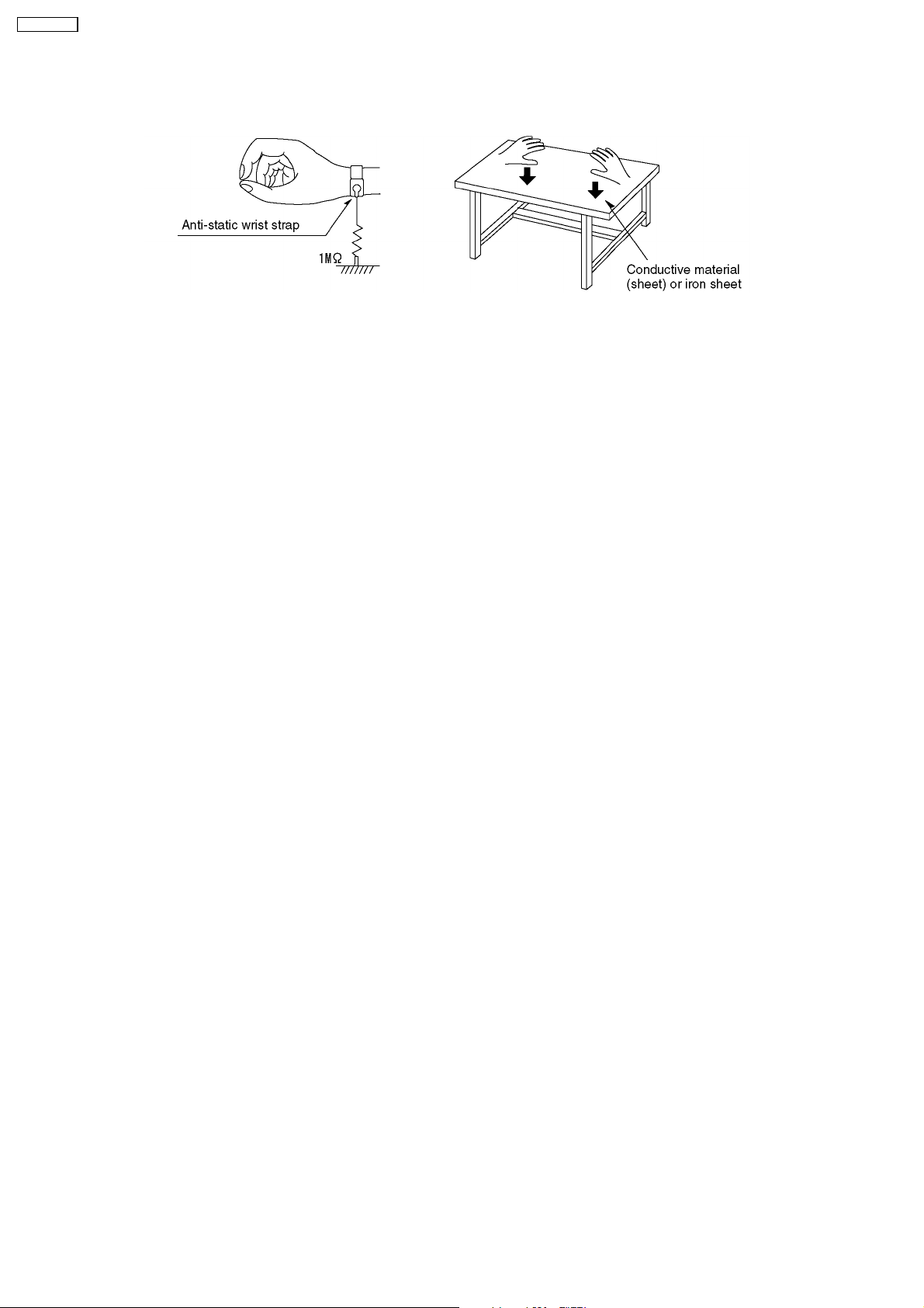
9.3. Grounding for electrostatic breakdown prevention
Some devices such as the DVD player use the optical pickup (laser diode) and the optical pickup will be damaged by static
electricity in the working environment. Proceed servicing works under the working environment where grounding works is
completed.
9.3.1. Worktable grounding
1. Put a conductive material (sheet) or iron sheet on the area where the optical pickup is placed, and ground the sheet.
15
SA-HT680PL
9.3.2. Human body grounding
1. Use the anti-static wrist strap to discharge the static electricity form your body.
16
SA-HT680PL
10 Disassembly Main Component Replacement Procedure
“ATTENTION SERVICER”
Some chassis components may have sharp edges.
Be careful when disassembling and servicing.
1. This section describes procedures for checking the operation of the major printed circuit boards and replacing the
main components.
2. For assembly after operation checks or replacement, reverse the respective procedures.
Special reassembly procedures are described only when required.
3. Select items from the following index when checks or replacement are required.
· Disassembling the Top Cabinet
· Disassembling the Front Panel
· Disassembling the CR16D Mechanism Unit
· Disassembling of Rear panel
· Disassembling the Main P.C.B.
· Disassemble of Regulator P.C.B.
· Disassemble of AC Intel P.C.B.
· Disassemble of Power P.C.B.
· Disassemble of FL P.C.B. & Power Button P.C.B.
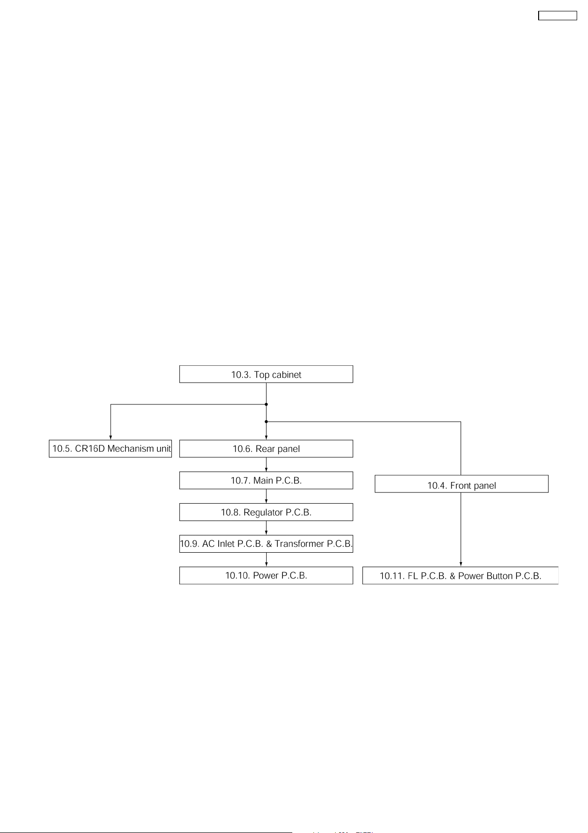
10.1. Disassembly Procedure
17
SA-HT680PL
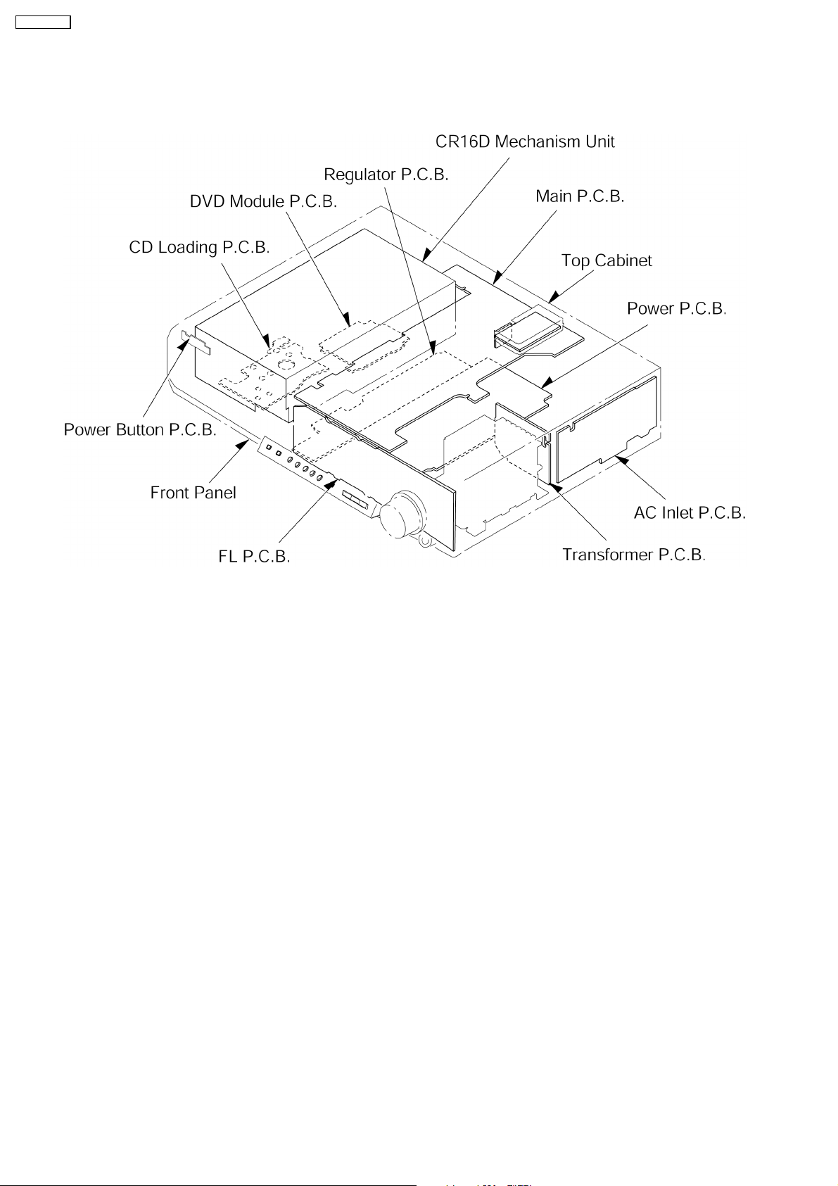
10.2. Main Components and P.C.B. Locations
18
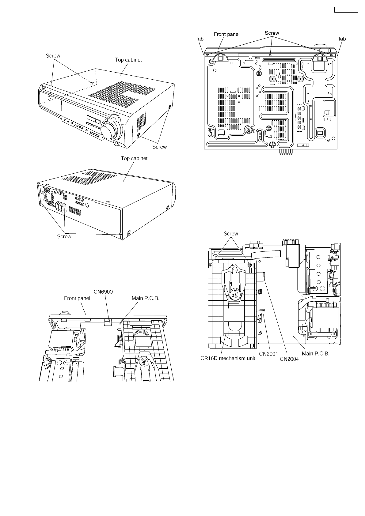
10.3. Disassemble Top Cabinet
Step 1 Unscrew the screws.
SA-HT680PL
Step 4 Remove front panel.
10.5. Disassemble CR16D
Mechanism Unit
Step 2 Lift up & remove the top cabinet.
10.4. Disassemble Front Panel
· Follow the (Step 1) - (Step 2) of Item 10.3.
Step 1 Detach FFC at connector. (CN6900)
· Follow the (Step 1) - (Step 2) of Item 10.3.
Step 1 Unscrew the screws.
Step 2 Detach FFC cable at connectors. (CN2001, CN2004)
Step 3 Lift the CR16D mechanism unit vertically.
· Note : Refer to section 11 for disassembly of the
mechanism unit.
Step 2 Unscrew the screws.
Step 3 Release the tabs.
19
SA-HT680PL
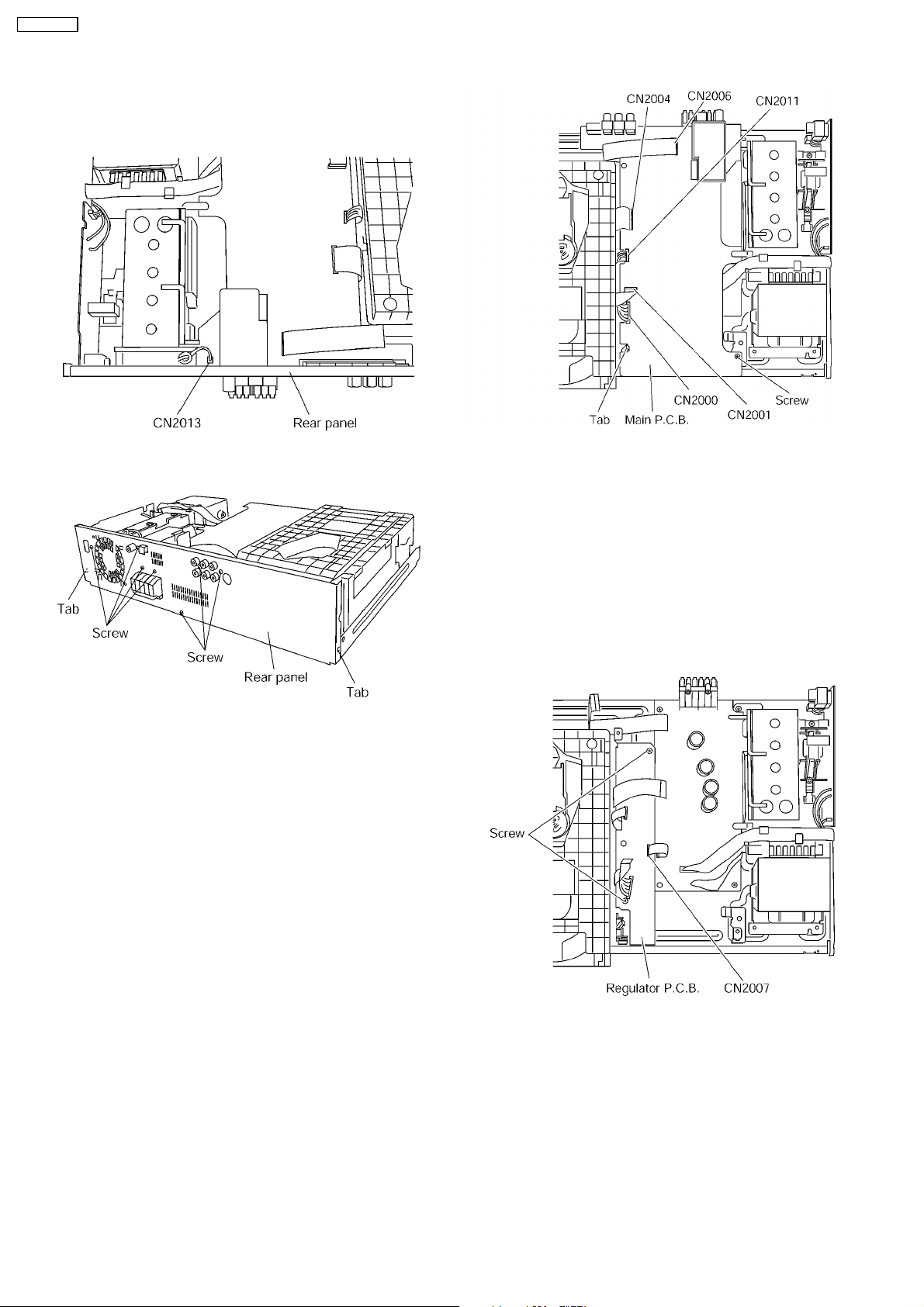
10.6. Disassemble Rear panel
· Follow the (Step 1) - (Step 2) of Item 10.3.
Step 1 Detach wire at the connector. (CN2013)
Step 2 Unscrew the screws.
Step 3 Release the tabs.
Step 4 Remove rear panel.
10.7. Disassemble Main P.C.B.
· Follow the (Step 1) - (Step 2) of Item 10.3.
· Follow the (Step 1) - (Step 4) of Item 10.6.
Step 1 Unscrew the screws.
Step 2 Detach FFC/wire at the connectors. (CN2000, CN2001,
CN2011, CN2004, CN2006)
Step 3 Release the tab.
Step 4 Remove Main P.C.B..
10.8. Disassemble of Regulator
P.C.B.
· Follow the (Step 1) - (Step 2) of Item 10.3.
· Follow the (Step 1) - (Step 4) of Item 10.6.
· Follow the (Step 1) - (Step 4) of Item 10.7.
Step 1 Unscrew the screws.
Step 2 Detach FFC at connector. (CN2007)
10.9. Disassemble of AC Inlet P.C.B.
& Transformer P.C.B.
· Follow the (Step 1) - (Step 2) of Item 10.3.
· Follow the (Step 1) - (Step 4) of Item 10.6.
· Follow the (Step 1) - (Step 4) of Item 10.7.
Step 1 Detach FFC/wire at connectors. (CN502, CN503)
20
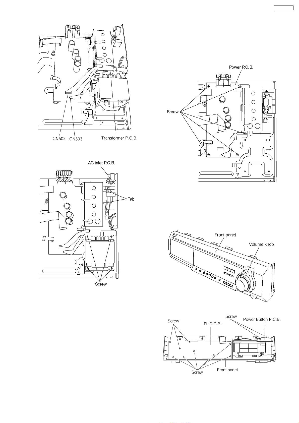
Step 2 Unscrew the screws.
Step 3 Release the tabs.
SA-HT680PL
10.10. Disassemble of Power P.C.B.
· Follow the (Step 1) - (Step 2) of Item 10.3.
· Follow the (Step 1) - (Step 4) of Item 10.6.
· Follow the (Step 1) - (Step 4) of Item 10.7.
Step 1 Unscrew the screws.
10.11. Disassemble FL P.C.B. &
Power Button P.C.B.
· Follow the (Step 1) - (Step 2) of Item 10.3.
· Follow the (Step 1) - (Step 4) of Item 10.4.
Step 1 Remove the volume knob.
Step 2 Unscrew the screws.
Step 3 Lift up FL & Power Button P.C.B.
21
SA-HT680PL
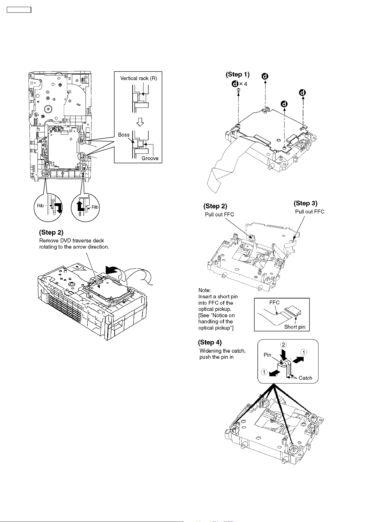
11 Assembling and Disassembling the Mechanism unit
11.1. Replacement for DVD traverse
deck
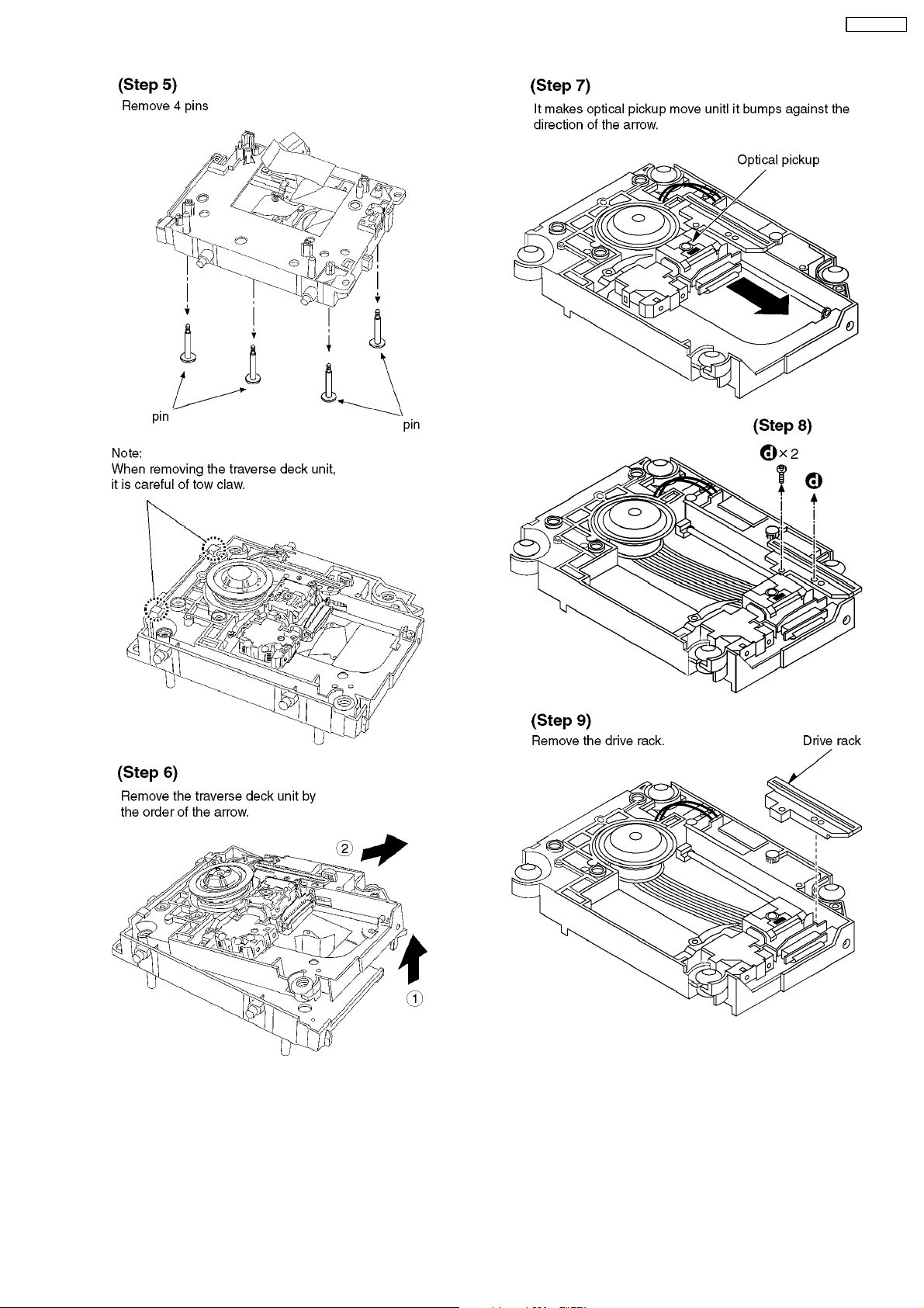
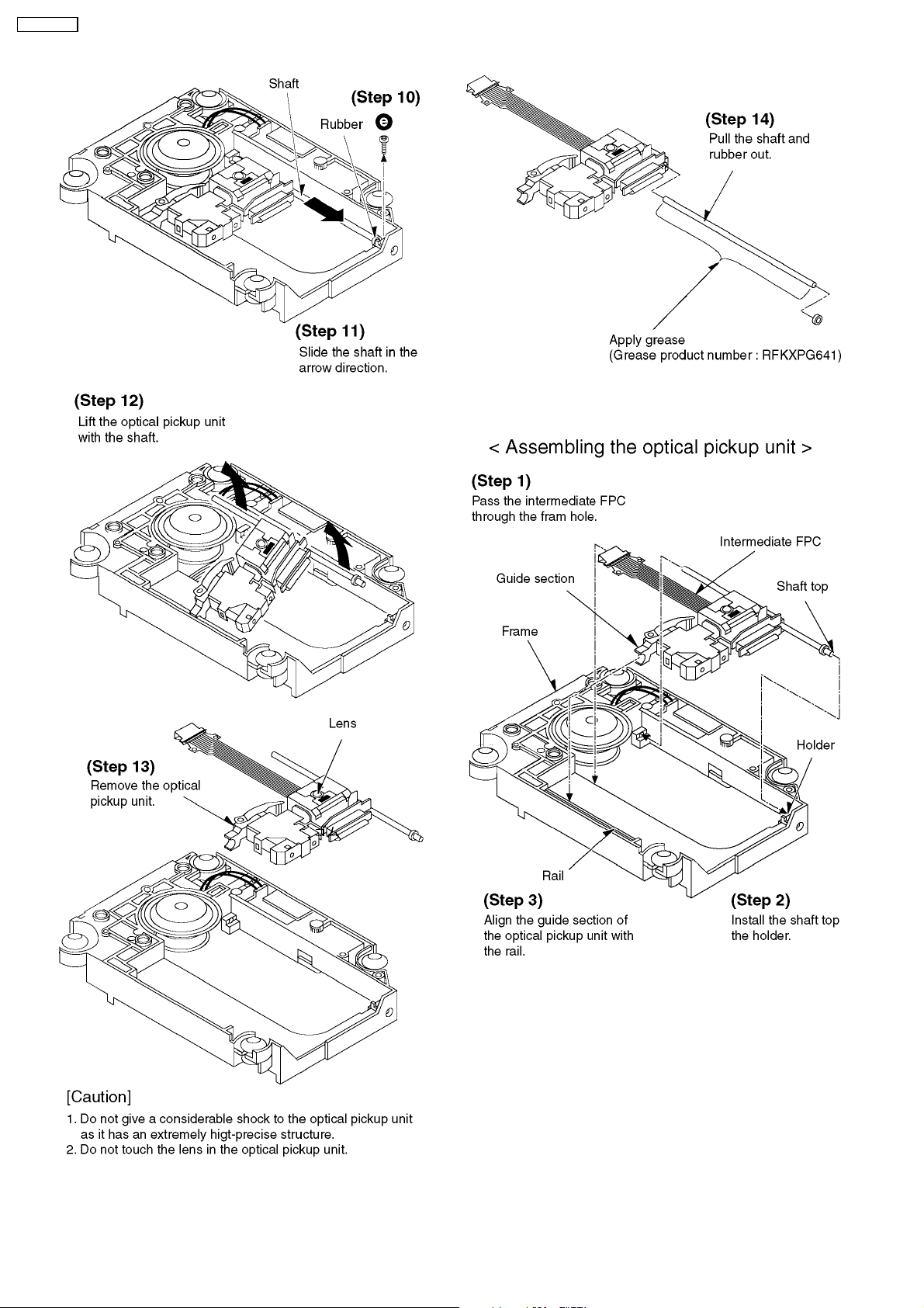
11.2. Replacement for optical
pickup unit
22
SA-HT680PL
23
SA-HT680PL
24
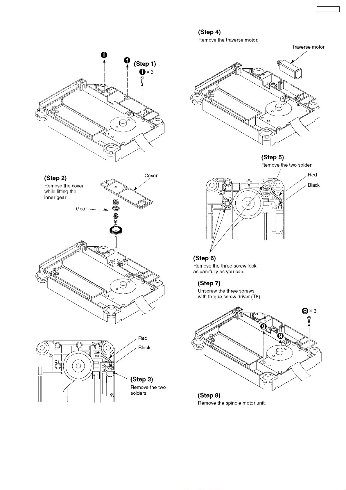
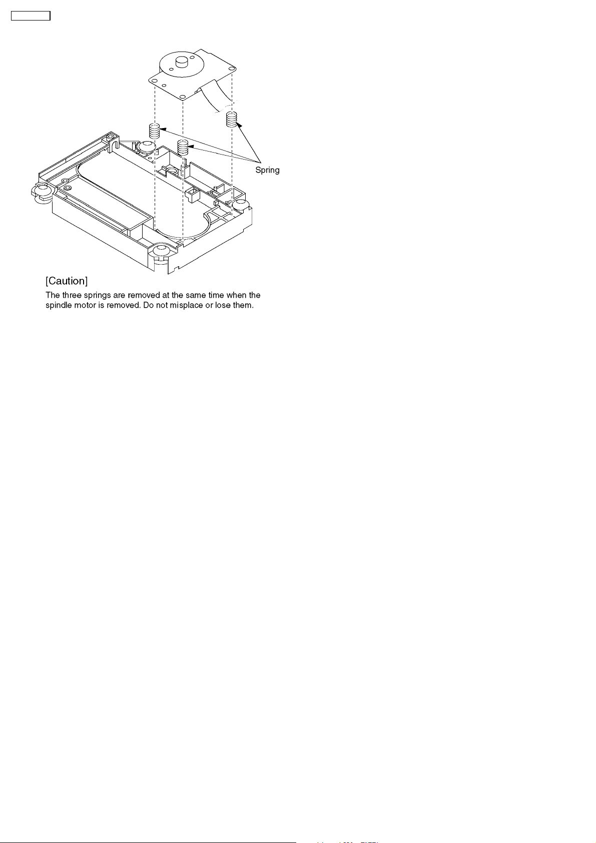
11.3. Assembling for traverse motor
and spindle motor
SA-HT680PL
25
SA-HT680PL
26
11.4. Procedure for removing CR16D mechanism unit
SA-HT680PL
1. Turn off by pressing power SW in the body.
2. Unplug AC power cord after the indication of [GOOD-BYE],
then disassemble the body.
3. Disassemble the body, and take out DVD loading
mechanism.
4. Perform disassembly according to the following procedure
for disassembly.
11.5. CR16 mechanism disassembly procedure
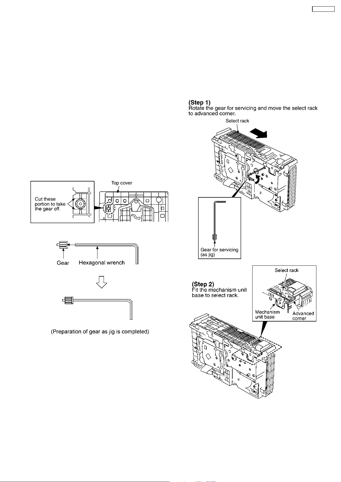
11.5.1. Gear for servicing information
· This unit has a gear which used for checking items
(open/close of disc tray, up/down operation of traverse unit
by manually) when servicing. (For gear information, that is
described on the items for disassembly procedures.)
· For preparation of gear (for servicing), perform the
procedures as follows.
· In case of re-servicing the same set, the “gear for servicing”
may be took off because it had been used. So, the “gear for
servicing” must be stored.
1. Remove the gear attached to top cover of DVD loading
mechanism.
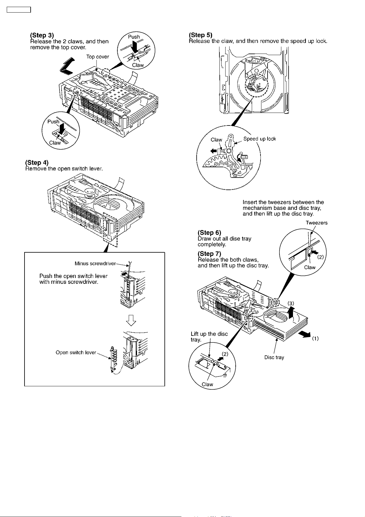
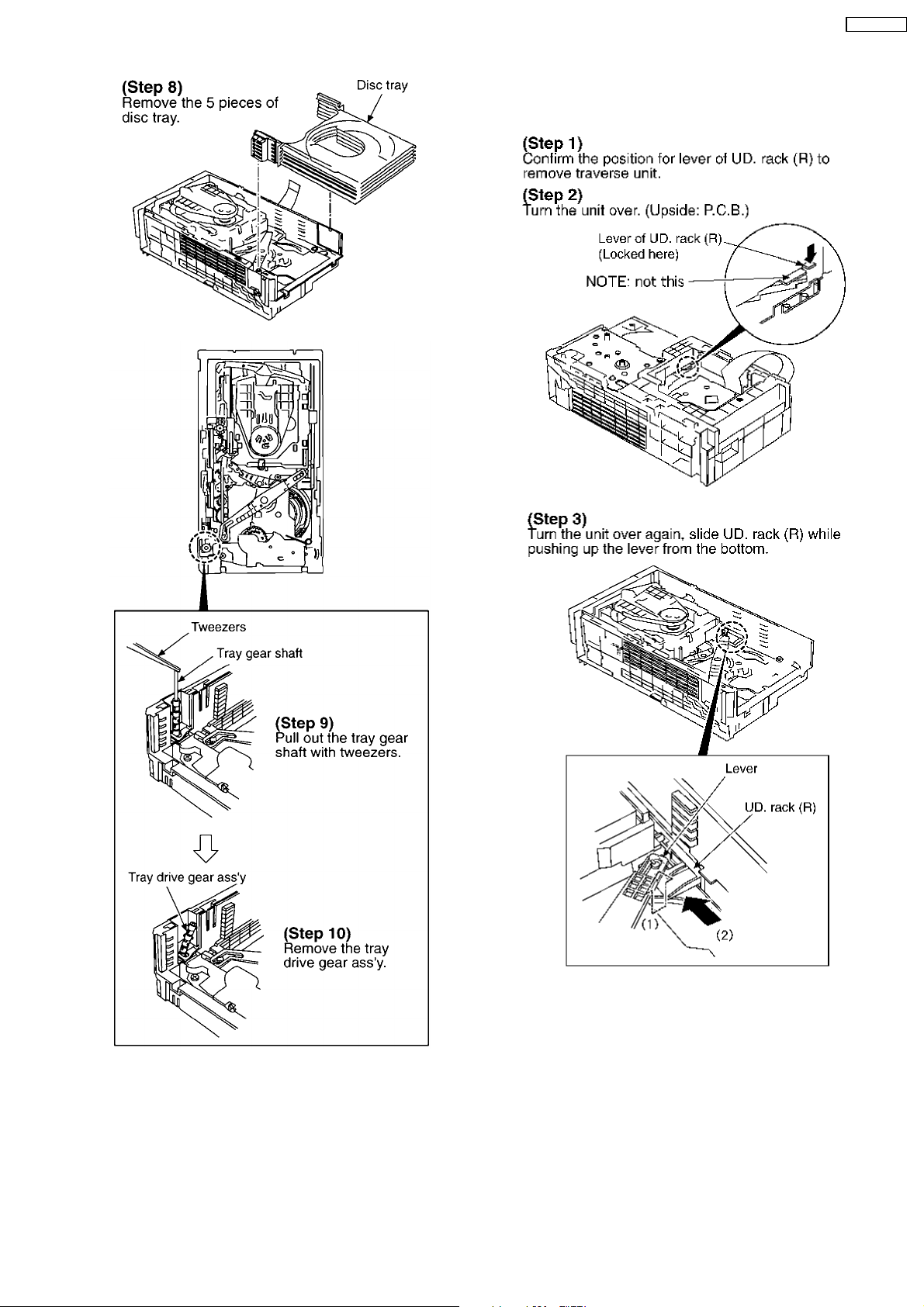
11.5.2. Replacement for the disc tray
2. Insert the hexagonal wrench (2.5mm) into the gear.
27
SA-HT680PL
28
SA-HT680PL
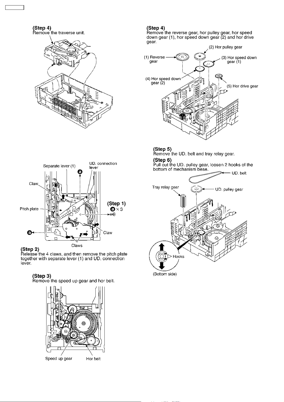
11.5.3. Replacement for the traverse deck
· Follow the (Step 1) - (Step 10) of item 11.5.2.
29
SA-HT680PL
11.5.4. Disassembly for DVD loading unit
· Follow the (Step 1) - (Step 10) of item 11.5.2.
· Follow the (Step 1) - (Step 4) of item 11.5.3.
30
 Loading...