

Panasonic SA-BTT105EB, SA-BTT105EG, SC-BTT105EB, SC-BTT105EG Service Manual
ORDER NO.AD1404016CE
Blu-ray DiscTM Home Theater Sound System
Model No.
Remote
Control
SB-HFS4010
Notes: Please refer to the original service manual for:
• Speaker system SB-HFS4010/HW4010, Order No:AD1403015CE
SA-BTT105
SB-HW4010
Colour:(K)...........Black Type
SA-BTT105EB
SA-BTT105EG
SC-BTT105EB
SC-BTT105EG
WARNING
This service information is designed for experienced repair technicians only and is not designed for use by the general
public. It does not contain warnings or cautions to advise non-technical individuals of potential dangers in attempting
to service a product. Products powered by electricity should be serviced or repaired only by experienced professional
technicians. Any attempt to service or repair the product or products dealt with in this service information by anyone else
could result in serious injury or death.
© Panasonic Corporation 2014
Unauthorized copying and distribution is a violation of law.

TABLE OF CONTENTS
PAGE
1 Safety Precautions ----------------------------------------------- 3
1.1. General Guidelines ----------------------------------------- 3
1.2. Leakage Current Cold Check ----------------------------- 3
1.3. Leakage Current Hot Check (See Figure 1.) --------- 3
1.4. Protection Circuitry------------------------------------------- 3
2 Warning -------------------------------------------------------------- 4
2.1. Prevention of Electrostatic Discharge (ESD)
to Electrostatically Sensitive (ES) Devices ----------- 4
2.2. Caution for AC Cord --------------------------------------- 5
2.3. Precaution of Laser Diode ------------------------------- 6
2.4. Static Electricity Protection Measures ----------------- 7
2.5. Ground for Electrostatic Breakdown
Prevention ---------------------------------------------------- 7
3 Service Navigation ----------------------------------------------- 8
3.1. Service Information ----------------------------------------- 8
3.2. How to Update Firmware ---------------------------------- 8
4 Specications ----------------------------------------------------- 11
4.1. Others (Licences) ------------------------------------------ 12
5 Location of Controls and Components ------------------- 13
6 Installation Instructions ---------------------------------------- 15
6.1.Speaker Connection- --------------------------------------- 15
6.2.Connection to a TV- ----------------------------------------- 15
6.3.FM Antenna Connection ----------------------------------- 15
7 Operating Instruction ------------------------------------------- 16
7.1. Take out the Disc from Drive Unit when the
Disc cannot be ejected by the OPEN/CLOSE
button ----------------------------------------------------------- 16
8 Multiple Pressing Function ------------------------------------ 17
8.1.About the Multiple Pressing of the Unit’sRemote
Control ---------------------------------------------------------- 17
8.2.How to enter the Special Modes using theMultiple
Pressing Function of the Unit’sRemote Control ------ 17
9 Service Mode ------------------------------------------------------ 20
9.1.About the Service Mode ----------------------------------- 20
9.2.Service Mode List ------------------------------------------- 21
9.3.Self-Diagnostics Functions -------------------------------- 22
10 Troubleshooting Guide --------------------------------------- 23
10.1. About Operation of Set ---------------------------------- 23
10.2. After Servicing --------------------------------------------- 24
11 Wiring Connection and Voltage Data --------------------- 32
12 Disassembly and Assembly Instructions --------------- 34
12.1.Disassembly Flow Chart --------------------------------- 34
12.2.P.C.B. Location --------------------------------------------- 34
12.3.Disassembly Procedure ---------------------------------- 35
13 Measurements and Adjustments -------------------------- 39
13.1.When Replacing the Mechanism Unit and/or
Digital P.C.B. Unit ------------------------------------------- 39
13.2.When Replacing the Front P.C.B.Unit and/or
NFC P.C.B. Unit. --------------------------------------------- 44
13.3.Caution for Replacing Parts ----------------------------- 47
14 Exploded View and Replacement Parts List ----------- 48
14.1. Replacement Parts List ---------------------------------- 48
14.2. Casing Parts & Mechanism Section ------------------ 49
14.3. Packing & Accessories Section ------------------------ 50
2 3
1 Safety Precautions
1.1. General Guidelines
1. IMPORTANT SAFETY NOTICE
There are special components used in this equipment which are important for safety. These parts are marked by in the
Schematic Diagrams, Circuit Board Layout, Exploded Views and Replacement Parts List. It is essential that these critical
parts should be replaced with manufacturer’s specied parts to prevent X-RADIATION, shock, re, or other hazards. Do not
modify the original design without permission of manufacturer.
2.An Isolation Transformer should always be used during the servicing of AC Adaptor whose chassis is not isolated from
the AC power line. Use a transformer of adequate power rating as this protects the technician from accidents resulting in
personal injury from electrical shocks. It will also protect AC Adaptor from being damaged by accidental shorting that may
occur during servicing.
3.When servicing, observe the original lead dress. If a short circuit is found, replace all parts which have been overheated or
damaged by the short circuit.
4.After servicing, see to it that all the protective devices such as insulation barriers, insulation papers shields are properly
installed.
5. After servicing, make the following leakage current checks to prevent the customer from being exposed to shock hazards.
1.2. Leakage Current Cold Check
1.Unplug the AC cord and connect a jumper between the two prongs on the plug.
2.Measure the resistance value, with an ohmmeter, between the jumpered AC plug and each exposed metallic cabinet part onthe
equipment such as screwheads, connectors, control shafts, etc. When the exposed metallic part has a return path to thechassis,
the reading should be between 1 MΩ and 5.2 MΩ. When the exposed metal does not have a return path to the chas-sis, the
reading must be innity.
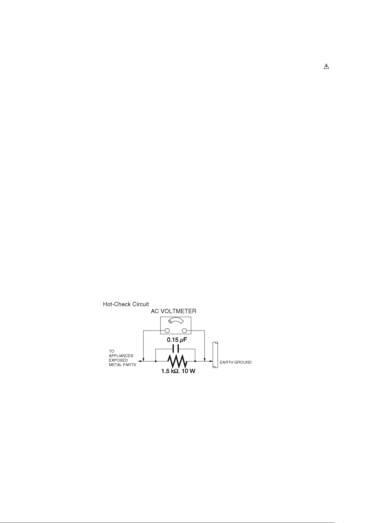
1.3. Leakage Current Hot Check (See Figure. 1)
1.Plug the AC cord directly into the AC outlet. Do not use an isolation transformer for this check.
2.Connect a 1.5 kΩ, 10 W resistor, in parallel with a 0.15 μF capacitor, between each exposed metallic part on the set and a
good earth ground, as shown in Figure. 1.
3.Use an AC voltmeter, with 1 kΩ/V or more sensitivity, to measure the potential across the resistor.
4.Check each exposed metallic part, and measure the voltage at each point.
5.Reverse the AC plug in the AC outlet and repeat each of the above measurements.
6.The potential at any point should not exceed 0.75 V RMS. A leakage current tester (Simpson Model 229 or equivalent)
maybe used to make the hot checks, leakage current must not exceed 1/2 mA. In case a measurement is outside of the
limitsspecied, there is a possibility of a shock hazard, and the equipment should be repaired and rechecked before it is
returned tothe customer.
1.4. Protection Circuitry
The protection circuitry may have operated if either of the following conditions are noticed:
•No sound is heard when the power is turned on.
•Sound stops during a performance.
The function of this circuitry is to prevent circuitry damage if, for example, the positive and negative speaker connection wires
are“shorted”, or if speaker systems with an impedance less than the indicated rated impedance of the amplier are used.If this
occurs, follow the procedure outlines below:
1.Turn off the power.
2.Determine the cause of the problem and correct it.
3.Turn on the power once again after one minute.
Note:
When the protection circuitry functions, the unit will not operate unless the power is rst turned off and then on again.
Figure. 1
3

2 Warning
2.1. Prevention of Electrostatic Discharge (ESD) to Electrostatically
Sensitive (ES) Devices
Some semiconductor (solid state) devices can be damaged easily by static electricity. Such components commonly are called
Electrostatically Sensitive (ES) Devices.
Examples of typical ES devices are IC(integrated circuits)and some field-effect transistors and
semiconductor “chip” components.
The following techniques should be used to help reduce the incidence of component damage caused by electrostatic
discharge(ESD).
1. Immediately before handling any semiconductor component or semiconductor-equipped assembly, drain off any ESD on
your body by touching a known earth ground. Alternatively, obtain and wear a commercially available discharging ESD
wrist strap, which should be removed for potential shock reasons prior to applying power to the unit under test.
2. After removing an electrical assembly equipped with ES devices, place the assembly on a conductive surface such as
aluminum foil, to prevent electrostatic charge buildup or exposure of the assembly.
3. Use only a grounded-tip soldering iron to solder or unsolder ES devices.
4. Use only an antistatic solder removal device. Some solder removal devices not classied as "antistatic (ESD protected)"
can generate electrical charge sufcient to damage ES devices.
5. Do not use freon-propelled chemicals. These can generate electrical charges sufcient to damage ES devices.
6. Do not remove a replacement ES device from its protective package until immediately before you are ready to install it.
(Most replacement ES devices are packaged with leads electrically shorted together by conductive foam, aluminum foil or
comparable conductive material).
7. Immediately before removing the protective material from the leads of a replacement ES device, touch the protective
material to the chassis or circuit assembly into which the device will be installed.
CAUTION :
Be sure no power is applied to the chassis or circuit, and observe all other safety precautions.
8. Minimize bodily motions when handling unpackaged replacement ES devices. (Otherwise harmless motion such as the
brushing together of your clothes fabric or the lifting of your foot from a carpeted oor can generate static electricity (ESD)
sufcient to damage an ES device).
IMPORTANT SAFETY NOTICE
There are special components used in this equipment which are important for safety. These parts are marked by
in the Schematic Diagrams, Circuit Board Diagrams, Exploded View and Replacement Parts List, It is essential that
these critical parts should be replaced with manufacturer’s specied, parts to prevent shock, re or other hazards, Do
not modify the original design without permission of manufacturer.
4 5
2.2. Caution for AC Cord
2.2.1. Information for Your Safety
2.2.2.1. Important
The wires in this mains lead are coloured in accordance with
the following code:
IMPORTANT
Your attention is drawn to the fact that recording of
prerecorded tapes or discs or other published or broadcast
material may infringe copyright laws.
WARNING
To reduce the risk of fire or shock hazard, do not expose
this equipment to rain or moisture.
CAUTION
To reduce the risk of fire or shock hazard and annoying
interference, use the recommended accessories only.
FOR YOUR SAFETY
DO NOT REMOVE THE OUTER COVER
To prevent electric shock, do not remove the cover. No
user serviceable parts inside. Refer servicing to qualified
service personnel.
2.2.2. Caution for AC Mains Lead
For your safety, please read the following text carefully.
This appliance is supplied with a moulded three-pin mains
plug for your safety and convenience.
A 5-ampere fuse is tted in this plug.
Should the fuse need to be replaced please ensure that the
replacement fuse has a rating of 5 amperes and it is
approved by ASTA or BSI to BS1362
Check for the ASTA mark or the BSI mark on the body of the
fuse.
.
Blue Neutral
Brown Live
As the colours of the wires in the mains lead of this
appliancemay not correspond with the coloured markings
identifying the terminals in your plug, proceed as follows:
The wire which is coloured BLUE must be connected to
the terminal in the plug which is marked with the letter N or
coloured BLACK.
The wire which is coloured BROWN must be connected to
the terminal in the plug which is marked with the letter L or
coloured RED.
Under no circumstances should either of these wires be
connected to the earth terminal of the three pin plug, marked
with the letter E or the Earth Symbol.
Earth Symbol
2.2.2.2. Before Use
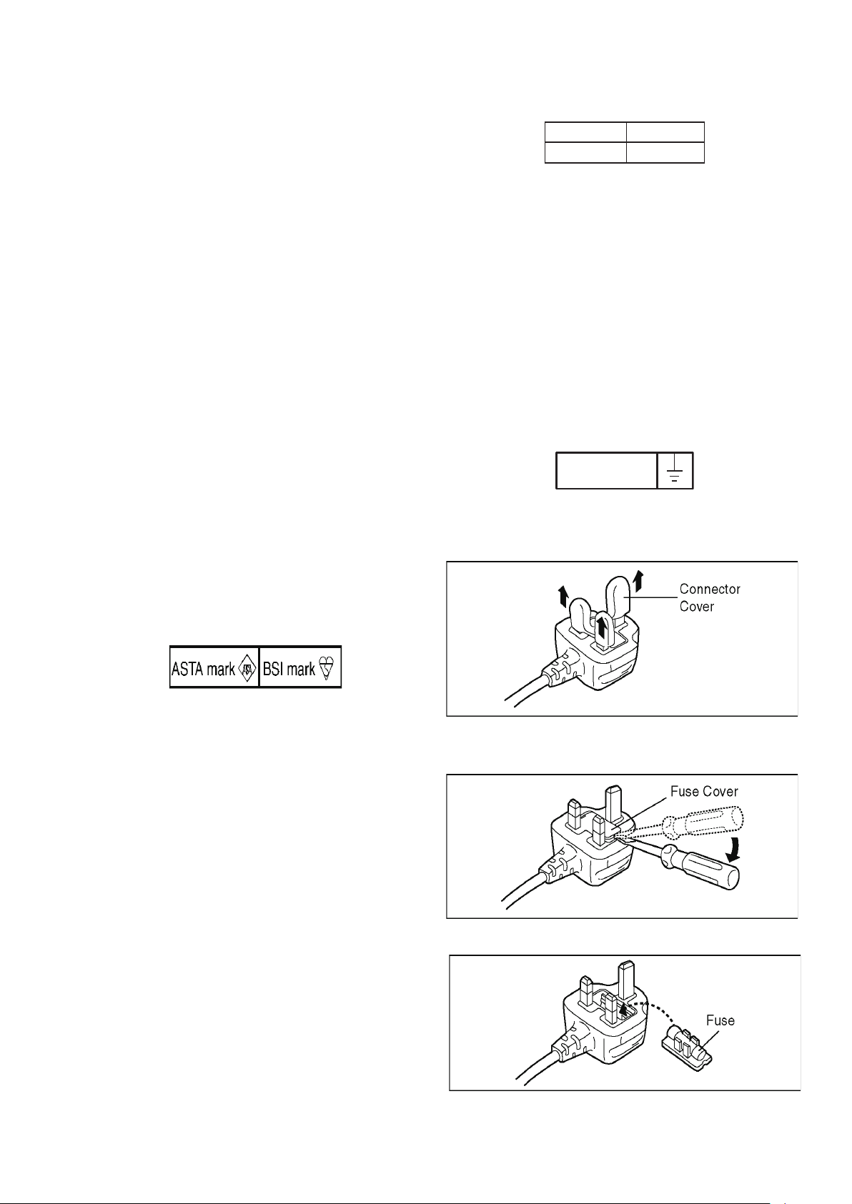
Remove the Connector Cover as follows:
If the plug contains a removable fuse cover you must ensure
that it is retted after the fuse is replaced.
If you lose the fuse cover, the plug must not be used until a
replacement cover is obtained.
A replacement fuse cover can be purchased from your local
Panasonic Dealer.
If the tted moulded plug is unsuitable for the socket outlet in
your home then the fuse should be removed and the plug cut
off and disposed of safety.
There is a danger of severe electrical shock if the cut off plug
is inserted into any 13-ampere socket.
If a new plug is to be tted please observe the wiring code as
shown below.
If in any doubt, please consult a qualied electrician.
2.2.2.3. How to Replace the Fuse
1. Remove the Fuse Cover with a screwdriver.
2. Replace the Fuse and attach the Fuse cover.
5
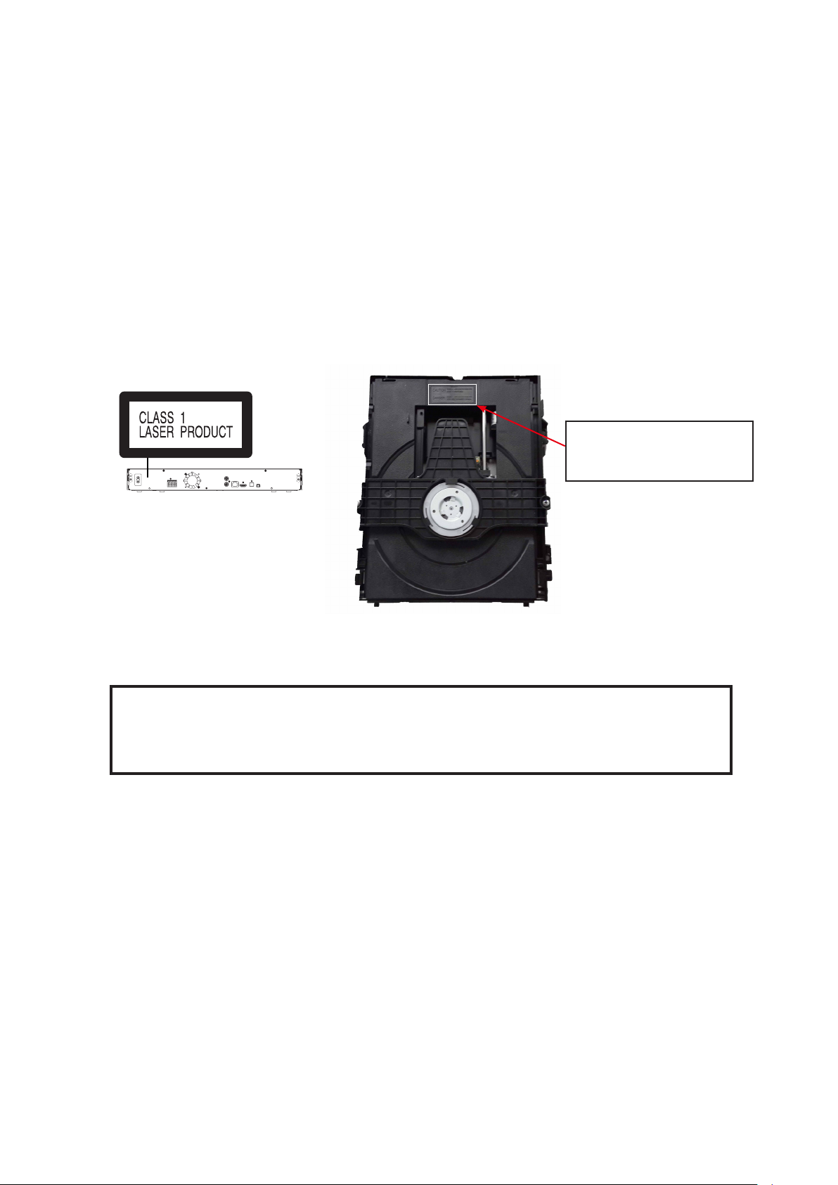
2.3. Precaution of Laser Diode
CAUTION :
This product utilizes a laser diode with the unit turned “on”,
invisible laser radiation is emitted from the pick-up lens.
Wave length:770 to 800 nm (CDs)/645 to 660 nm (DVDs)
Maximum output radiation power from pick-up:100 μW/
VDE Laser radiation from the pick-up lens is safety level,
but be sure the followings:
1. Do not disassemble the optical pick-up unit, since
radiation from exposed laser diode is dangerous.
2. Do not adjust the variable resistor on the pick-up unit, it
was already adjusted.
3. Do not look at the focus lens using optical instruments.
4. Recommend not to look at pick-up lens for a long time.
INVISIBLE LASER RADIATION WHEN OPEN
CAUTION
DO NOT STARE INTO BEAM.
INVISIBLE LASER RADIATION WHEN OPEN
DANGER
AVOID DIRECT EXPOSURE TO THE BEAM.
Back of product
CAUTION !
THIS PRODUCT UTILIZES A LASER.
USE OF CONTROLS OR ADJUSTMENTS OR PERFORMANCE OF PROCEDURES OTHER THAN
THOSE SPECIFIED HEREIN MAY RESULT IN HAZARDOUS RADIATION EXPOSURE.
6 7
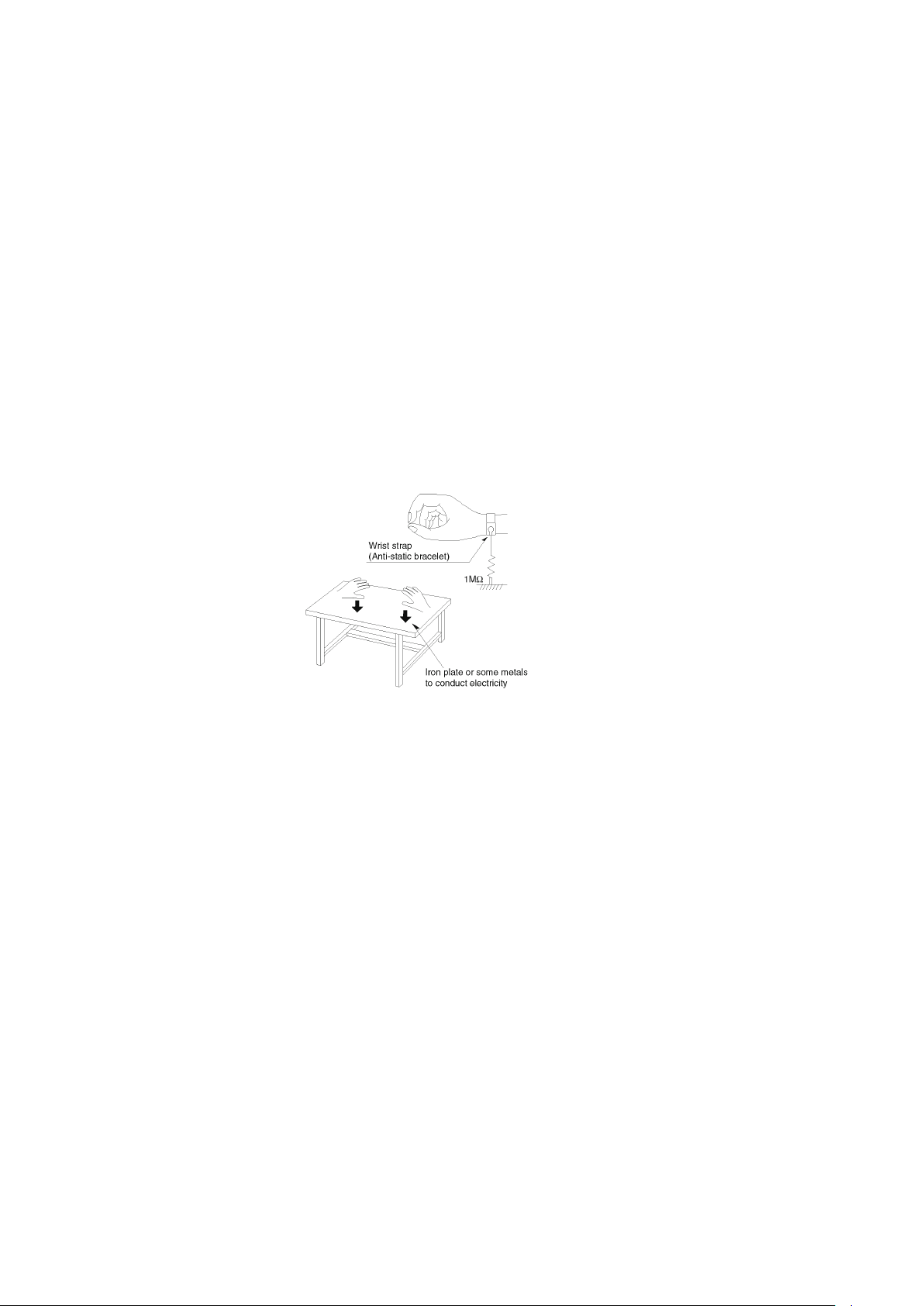
2.4. Static Electricity Protection Measures
• The laser diode in the traverse unit (optical pick-up) may break down due to potential difference caused by static electricity
of clothes or human body.
So, be careful of electrostatic breakdown during repair of the traverse unit (optical pick-up).
2.5. Ground for Electrostatic Breakdown Prevention
• As for parts that use optical pick-up (laser diode), the optical pick-up is destroyed by the static electricity of the working
environment.
Repair in the working environment that is grounded.
2.5.1. Work table grounding
• Put a conductive material (sheet) or steel sheet on the area where the traverse unit (optical pick-up) is placed, and ground
the sheet.
2.5.2. Human body grounding
• Use the anti-static wrist strap to discharge the static electricity from your body.
2.5.3. When exchanging the Drive
• Before remove the ESD prevention bag, make sure to use the anti-static wrist strap to discharge the static electricity when
replace the Drive.
Note:
The ESD prevention bag is used to replace the original short-circuit point.
It can be removed while placing the Drive.
7
3 Service Navigation
Occasionally, Panasonic may release updated
firmware for this unit that may add or improve the
way a feature operates. These updates are
available free of charge.
This unit is capable of checking the firmware
automatically when connected to the Internet via
a broadband connection.
When a new firmware version is available, the
following message is displayed.
Firmware Update
Current Version: X.XX
New Version: X.XX
Do you want to start firmware update?
For the update information, please visit the
following website:
http://panasonic.net/support/
Yes No
OK
RETURN
3.1. Service Information
This service manual contains technical information, which allow service personnels to understand and service this model.
Please place orders with the numbers in the parts list and not the numbers in the explossion illustration.
If the circuit is changed or modied, the information will be followed by service manual to be controlled with original service
manual.
Note:
The replacement parts of this model is supplied as block unit.
Please use Troubleshooting Guide for your reference of the repair.
3.2. How to Update Firmware
The rmwareof the unit may be renewed to improve the quality including operational performance and playability.Make sure to
refer the following procedure when performing version-up.
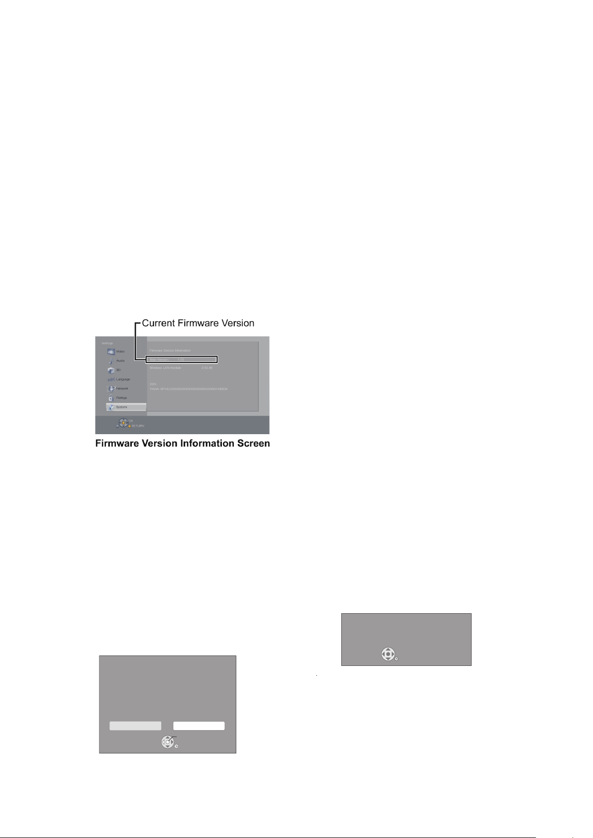
3.2.1. Conrmation of the Firmware Version
Perform following steps to checking the rmware version currently installed in the unit.
1. Turn the unit on.
2. When the home screen is display,Select [Setup] → [Settings] → [System] → [System Information] → [Firmware
Version Information].
3. Firmware Version Information screen is displayed.
3.2.2. Updating Firmware
This unit has 2 updating methods, one way to update via the internet, the other way to update using CD-R or USB device
which is stored pre-downloaded rmware update le.
3.2.2.1. Updating Firmware via the Internet
Occasionally, Panasonic may release updated
firmware for this unit that may add or improve the
way a feature operates. These updates are
available free of charge.
This unit is capable of checking the firmware
automatically when connected to the Internet via
a broadband connection.
When a new firmware version is available, the
following message is displayed.
Firmware Update
New Version: X.XX
Current Version: X.XX
Do you want to start firmware update?
For the update information, please visit the
following website:
http://panasonic.net/support/
Yes No
OK
RETURN
DO NOT DISCONNECT the unit from the AC
power or perform any operation while the update
is in process.
After the firmware is installed, “FIn” will be
displayed on the unit’s display. Unit will restart
and the following screen will be displayed.
The firmware was updated.
Current Version
:
x.xx
RETURN
8 9
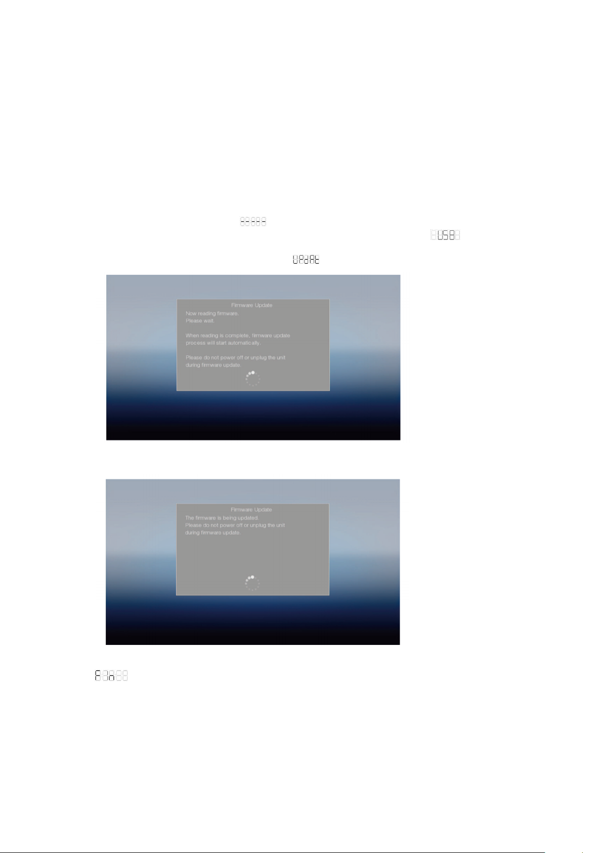
3.2.2.2. Updating rmware using the USB device
When using the USB device to update the rmware.
(When using CD-R instead of USB device, perform same the procedures)
1.Download the latest rmware le of the unit.
The latest rmware required for version-up can be downloaded from “Support Information from NWBG/VDBG PAVC”web-
sitein “TSN system”.
Click le name to download.
After download, click le to decompress. (Total: 1 le).
2.Decompress the downloaded le.
The decompressed le will be named as follows.
File Name: PANA_HTS.FRM
Copy the le to root diretory of the USB device.
(If using CD-R instead of USB device, burn the le to a blank CD-R by a writing software.)
3.Update the unit.
1.Tunr the unit power on.
2.After the home screen is displayed and appears at LED display of the front panel,insert the USB device stored
downloaded latest rmware le to the front USB port of the unit(LED display change to ).(or insert the CD-R into
the unit and playback it.)
3.TV will show the rmware Update UI automatically and is displayed at LED display.
4.Wait for the rmware update.
5.when is displayed,update process is nished.
Remove the USB device (or the CD-R) and press the POWER button to turn the unit off.
6.Turn the unit on and the home screen appears the rmware update is completed.
9

5.If the TV show the rmware update is complete ( is displayed at LED display).
Remove the USB device (or the CD-R) and press the POWER button to turn the unit off.
6.Turn the unit on and the home screen appears the rmware update is completed.
10 11
4 Specications
Reference
Specifications
SPEAKER SECTION
Woofer
Full range
Super
SPEAKER SECTION
Woofer
CONE TYPE
(cm)
Full range
CONE TYPE
(cm)
Super
tweeter
Piezo type
[BTT465]
Front j 6.5 k1
Centre j 6.5 k2
Surround j 6.5 k1
Subwoofer 16 jj
[BTT405]
Front j 6.5 k1
Centre j 6.5 k2
Surround j 6.5 k1
Subwoofer 16 jj
[BTT105]
Front j 6.5 k1
Subwoofer 16 jj
(W (mm)kH (mm)kD (mm))
(Approx. kg)
Reference
File format
File format Extension Reference
MKV
“.MKV”, “.mkv” ≥ The video file and
subtitles text file are
inside the same
folder, and the file
names are the same
except for the file
extensions.
≥ Some MKV/Xvid files
may not be played
back correctly,
depending on the
video resolution,
frame rate condition,
subtitle format and
so on.
Subtitles text file
“.SRT”, “.srt”,
“.SSA”, “.ssa”,
“.ASS”, “.ass”
Xvid
“.AVI”, “.avi”
Subtitles text file
“.SRT”, “.srt”,
“.SUB”, “.sub”,
“.TXT”, “.txt”
mp4
Some mp4/MPEG files
Reference
Specifications
p The impedance of all the speakers is 4 j.
GENERAL
Power consumption [BTT465]
Approx. 89 W
[BTT405]
Approx. 64 W
[BTT105]
Approx. 46 W
Power consumption in
standby mode
Approx. 0.5 W
Power supply AC 220 V to 240 V, 50 Hz
Dimensions (W
MHMD)
430 mm M 55 mm M 322 mm
Mass [BTT465]
Approx. 2.7 kg
[BTT405] [BTT105]
Approx. 2.6 kg
Operating temperature
range
0 QC to 40 QC
Operating humidity
range
35 % to 80 % RH
(no condensation)
LASER Specification Class 1 LASER Product
Wave length: 790 nm (CDs)/
658 nm (DVDs)/405 nm (BDs)
Laser power: No hazardous
radiation is emitted with the
safety protection
AMPLIFIER SECTION
RMS TTL POWER
OUTPUT [BTT465]
1000 W
1 kHz, 30 % total harmonic distortion
FRONT:
CENTRE:
SURROUND:
167 W per ch (4 j)
167 W (4 j)
167 W per ch (4 j)
55 Hz, 30 % total harmonic distortion
SUBWOOFER:
167 W (4 j)
RMS TTL POWER
OUTPUT [BTT405]
600 W
1 kHz, 30 % total harmonic distortion
FRONT:
CENTRE:
SURROUND:
100 W per ch (4 j)
100 W (4 j)
100 W per ch (4 j)
55 Hz, 30 % total harmonic distortion
SUBWOOFER:
100 W (4 j)
SPEAKER SECTION
Woofer
CONE TYPE
(cm)
Full range
CONE TYPE
(cm)
Super
tweeter
Piezo type
[BTT465]
Front L 6.5 M1
Centre L 6.5 M2
Surround L 6.5 M1
Subwoofer 16 LL
[BTT405]
Front L 6.5 M1
Centre L 6.5 M2
Surround L 6.5 M1
Subwoofer 16 LL
[BTT105]
Front L 6.5 M1
Subwoofer 16 LL
Dimensions
(W (mm)MH (mm)MD (mm))
Mass
(Approx. kg)
[BTT465]
Front 270 M1181 M270 2.7
Centre 304 M87 M77 0.7
Surround 83 M141 M75 0.5
Subwoofer 156 M290 M263 3.4
[BTT405]
Front 83 M141 M75 0.5
Centre 304 M87 M77 0.7
Surround 83 M141 M75 0.5
Subwoofer 156 M290 M263 3.4
[BTT105]
Front 83 M141 M75 0.5
Subwoofer 156 M290 M263 3.4
TERMINAL SECTION
USB slot USB2.0
1 system
Ethernet 10BASE-T/100BASE-TX
1 system
Bluetooth® SECTION
Bluetooth
®
Version 4.0
Class 2
2.4 GHz Band FH-SS
Supported Profile:
A2DP/AVRCP
Supported Codec:
SBC/AAC
Reference
Specifications
GENERAL
Power consumption [BTT465]
Approx. 89 W
[BTT405]
Approx. 64 W
[BTT105]
Approx. 46 W
Power consumption in
standby mode
Approx. 0.5 W
Power supply AC 220 V to 240 V, 50 Hz
Dimensions (W
MHMD)
430 mm M 55 mm M 322 mm
Mass [BTT465]
Approx. 2.7 kg
[BTT405] [BTT105]
Approx. 2.6 kg
Operating temperature
range
0 QC to 40 QC
Operating humidity
range
35 % to 80 % RH
(no condensation)
LASER Specification Class 1 LASER Product
Wave length: 790 nm (CDs)/
658 nm (DVDs)/405 nm (BDs)
Laser power: No hazardous
radiation is emitted with the
safety protection
SPEAKER SECTION
Woofer
CONE TYPE
(cm)
Full range
CONE TYPE
(cm)
Super
tweeter
Piezo type
[BTT465]
Front L 6.5 M1
Centre L 6.5 M2
Surround L 6.5 M1
Subwoofer 16 LL
[BTT405]
Front L 6.5 M1
Centre L 6.5 M2
Surround L 6.5 M1
Subwoofer 16 LL
[BTT105]
Front L 6.5 M1
Subwoofer 16 LL
Dimensions
(W (mm)MH (mm)MD (mm))
Mass
(Approx. kg)
[BTT465]
Front 270 M1181 M270 2.7
Centre 304 M87 M77 0.7
Surround 83 M141 M75 0.5
Subwoofer 156 M290 M263 3.4
[BTT405]
Front 83 M141 M75 0.5
Centre 304 M87 M77 0.7
SPEAKER SECTION
Woofer
CONE TYPE
(cm)
Full range
CONE TYPE
(cm)
Super
tweeter
Piezo type
[BTT465]
Front j 6.5 k1
Centre j 6.5 k2
Surround j 6.5 k1
Subwoofer 16 jj
[BTT405]
Front j 6.5 k1
Centre j 6.5 k2
Surround j 6.5 k1
Subwoofer 16 jj
[BTT105]
Front
6.5
1
SPEAKER SECTION
Woofer
CONE TYPE
(cm)
Full range
CONE TYPE
(cm)
Super
tweeter
Piezo type
[BTT465]
Front j 6.5 k1
Centre j 6.5 k2
Surround j 6.5 k1
Subwoofer 16 jj
[BTT405]
Front j 6.5 k1
Centre j 6.5 k2
Surround j 6.5 k1
Subwoofer 16 jj
[BTT105]
Front j 6.5 k1
Subwoofer 16 jj
Dimensions
(W (mm)kH (mm)kD (mm))
Mass
(Approx. kg)
[BTT465]
Front 270 k1181 k270 2.7
Centre 304 k87 k77 0.7
Surround 83 k141 k75 0.5
Subwoofer 156 k290 k263 3.4
[BTT405]
Front 83 k141 k75 0.5
Centre 304 k87 k77 0.7
Surround 83 k141 k75 0.5
Subwoofer 156 k290 k263 3.4
[BTT105]
Front 83
141 k75 0.5
GENERAL
Power consumption Approx. 46W
Power consumption in
standby mode
Power supply AC 220V to 240V, 50 Hz
Dimensions (W x H x D) 430mm x 55mm x 322mm
Mass Approx. 2.6kg
Operating temperature
range
Operating humidity
range
LASER Specication Class 1 LASER Product
AMPLIFIER SECTION
RMS TTL POWER
OUTPUT [BTT105]
Audio Input AUX M 1
Digital Audio Input Optical M 1
Approx. 0.5W
0 oC to 40 oC
35% to 80% RH
(no condensation)
Wave length: 790nm(CDs)/
658nm(DVDs)/405nm(BDs)
Laser power: No hazardous
radiation is emitted with the
safety protection
300 W
1 kHz, 30 % total harmonic distortion
FRONT: 100 W per ch (4 j)
55 Hz, 30 % total harmonic distortion
SUBWOOFER:
Sampling frequency:
32 kHz, 44.1 kHz, 48 kHz
Audio Format:
PCM, Dolby Digital, DTS
100 W (4 j)
SPEAKER SECTION
Woofer
CONE TYPE
(cm)
j
Subwoofer 16 jj
Dimensions
k
®
11
Subwoofer 156 k290 k263 3.4
≥ The impedance of all the speakers is 4 ≠.
TERMINAL SECTION
USB slot USB2.0
Ethernet 10BASE-T/100BASE-TX
1 system
1 system
Bluetooth® SECTION
Bluetooth
®
Version 4.0
Class 2
2.4 GHz Band FH-SS
Supported Profile:
A2DP/AVRCP
Supported Codec:
SBC/AAC
FM TUNER SECTION
Frequency range 87.50 MHz to 108.00 MHz
Antenna terminals 1 with Antenna Cable (1.2 m)
(50 kHz step)
VIDEO SECTION
Signal system PAL/NTSC
HDMI AV output* Output connector:
* This unit supports “HDMI CEC” function.
Specifications are subject to change without notice.
Type A (19 pin) 1 system
Full range
CONE TYPE
(cm)
Super
tweeter
Piezo type
k
Mass
4.1. Others (Licenses)
P-VQT5F60~Body_mst.fm 45 ページ 2014年1月24日 金曜日 午後4時14分
“AVCHD” is a trademark of Panasonic Corporation and Sony
Corporation.
Java is a registered trademark of Oracle and/or its affiliates.
Manufactured under license from Dolby Laboratories.
Dolby, Pro Logic, and the double-D symbol are trademarks of
Dolby Laboratories.
For DTS patents, see http://patents.dts.com. Manufactured under
license from DTS Licensing Limited. DTS, DTS-HD, the Symbol, &
DTS and the Symbol together are registered trademarks, and
DTS-HD Master Audio | Essential is a trademark of DTS, Inc. ©
DTS, Inc. All Rights Reserved.
HDMI, the HDMI Logo, and High-Definition Multimedia Interface
are trademarks or registered trademarks of HDMI Licensing LLC in
the United States and other countries.
This product is licensed under the AVC patent portfolio license and
VC-1 patent portfolio license for the personal and non-commercial
use of a consumer to (i) encode video in compliance with the AVC
Standard and VC-1 Standard (“AVC/VC-1 Video”) and/or (ii)
decode AVC/VC-1 Video that was encoded by a consumer
engaged in a personal and non-commercial activity and/or was
obtained from a video provider licensed to provide AVC/VC-1
Video. No license is granted or shall be implied for any other use.
Additional information may be obtained from MPEG LA, LLC.
See http://www.mpegla.com
MPEG Layer-3 audio coding technology licensed from Fraunhofer
IIS and Thomson.
“DVD Logo” is a trademark of DVD Format/Logo Licensing
Corporation.
“Wi-Fi”, “Wi-Fi Protected Setup”, “WPA” and “WPA2” are marks or
registered marks of the Wi-Fi Alliance.
The Bluetooth® word mark and logos are owned by the Bluetooth
SIG, Inc. and any use of such marks by Panasonic Corporation is
under license.
Other trademarks and trade names are those of their respective
owners.
Android is a trademark of Google Inc.
.
Copyright 2004-2013 Verance Corporation. CinaviaTM is a Verance
Corporation trademark. Protected by U.S. Patent 7,369,677 and
worldwide patents issued and pending under license from Verance
Corporation. All rights reserved.
This product incorporates the following software:
(1) the software developed independently by or for Panasonic
Corporation,
(2) the software owned by third party and licensed to Panasonic
Corporation,
(3) the software licensed under the GNU General Public License,
Version 2.0 (GPL V2.0),
(4) the software licensed under the GNU LESSER General Public
License, Version 2.1 (LGPL V2.1), and/or
(5) open source software other than the software licensed under
the GPL V2.0 and/or LGPL V2.1.
The software categorized as (3) - (5) are distributed in the hope
that it will be useful, but WITHOUT ANY WARRANTY, without
even the implied warranty of MERCHANTABILITY or FITNESS
FOR A PARTICULAR PURPOSE. Please refer to the detailed
terms and conditions thereof shown in the Settings menu.
At least three (3) years from delivery of this product, Panasonic will
give to any third party who contacts us at the contact information
provided below, for a charge no more than our cost of physically
performing source code distribution, a complete machine-readable
copy of the corresponding source code covered under GPL V2.0,
LGPL V2.1 or the other licenses with the obligation to do so, as
well as the respective copyright notice thereof.
Contact Information: oss-cd-request@gg.jp.panasonic.com
The source code and the copyright notice are also available for
free in our website below.
http://panasonic.net/avc/oss/theater/AWTHT14A.html
(1) MS/WMA
This product is protected by certain intellectual property rights of
Microsoft Corporation and third parties. Use or distribution of such
technology outside of this product is prohibited without a license from
Microsoft or an authorized Microsoft subsidiary and third parties.
(2) MS/PlayReady/Final Product Labeling
This product contains technology subject to certain intellectual
property rights of Microsoft. Use or distribution of this technology
outside of this product is prohibited without the appropriate
license(s) from Microsoft.
(3) MS/PlayReady/End User Notices
Content owners use Microsoft PlayReady™ content access
technology to protect their intellectual property, including copyrighted
content. This device uses PlayReady technology to access
PlayReady-protected content and/or WMDRM-protected content. If
the device fails to properly enforce restrictions on content usage,
content owners may require Microsoft to revoke the device’s ability to
consume PlayReady-protected content. Revocation should not affect
unprotected content or content protected by other content access
technologies. Content owners may require you to upgrade PlayReady
to access their content. If you decline an upgrade, you will not be able
to access content that requires the upgrade.
(4) Vorbis, FLAC, WPA Supplicant
The software licenses are displayed when “License” in the Setup
menu is selected. (> 32)
12 13
5 Location of Controls and Components
Getting started
21
10
23
24
15
22
20
19
11
12
13
18
17
25
14
R6/LR6, AA
Remote control
リワヱヶヵ
1
モヷ
2
3
4
5
6
7
8
9
ヴユロユヤヵヰン
ヴユモンヤラ ヴユモンヤラ
ヴレリヱ
ヵ
ユ
ワ
チ
ン
ユ
ヵ
ワ
リ
モヶュリヰ
ヱロモヺ
ヴロヰヸ
ヱモヶヴユ
ヴヵヰヱ
ヮ
ヰ
ユ
ラ
ヱリヱ
ヴレリヱ
ユヹリヵ
ヵ
ヱ
ヰ
ヰ
ヱ
ヱ
ノ
ヶ
ヱ
チ
ヮ
ユ
ワ
ヶ
ンユヵヶンワ
チ
ヮ
ユ
ワ
ヶ
Using the remote control
L) matches those in the remote control.
> 10)
16
K
1 Turn the unit on and off
2 Select title numbers, etc./Enter numbers
3 Cancel
®
4 Select Bluetooth
/Enable pairing (> 20)
5 Select an audio or video source
6 Basic playback control buttons (> 17)
7 Select preset radio stations (> 22)
8 Show the status messages (> 18)
9 Show the Home Screen of the Network
Service (> 23)
10 [,,,] : Move the highlight for selection
[OK] : Confirm the selection
) : Frame-by-frame (>17)
(
11 Show Option menu (> 24)
12 Coloured buttons (red, green, yellow, blue)
Used for various purposes depending on the
display
13 Set the sound effects (> 25)
14 Set the sleep timer
Press [SLEEP].
While “SL ``” is displayed on the unit’s
display, press [SLEEP] several times to
select the time (in minutes).
p Timer selection is up to 120 minutes.
p Select “OFF” on the unit’s display to disable
the function.
p To confirm the remaining time
Press the button again.
15 TV operation buttons
[¦ TV]: Turn the TV on and off
[AV, INPUT]: Switch the input select
[KLVOL] : Adjust the volume
16 Adjust the volume of the main unit
17 Change audio (> 17)
18 Mute the sound
p “MUtE” flashes on the unit’s display, while
the function is on.
p To cancel, press the button again or adjust
the volume.
p Muting is cancelled if the unit is turned off.
19 Switch Secondary Video on/off
(Picture-in-picture) (> 24)
20 Select radio stations manually (> 22)
21 Exit the Menu screen
22 Show HOME menu (> 15)
23 Show Pop-up Menu/Top Menu (> 18)
24 Return to previous screen
25 Show Setup menu (> 26)
13
1 Disc tray
Main unit (Front)
4231 5 67
89
10
5%$662836(AOUVDQQMࡍࠫ㧞㧜㧝㧠ᐕ㧝㧝㧣ᣣޓ㊄ᦐᣣޓඦᓟ㧡ᤨ㧡㧢ಽ
2 Display
Unit’s display list
3 Remote control signal sensor
Distance: Within approx. 7 m (23 feet).
Angle: Approx. 20G up and down, 30G left and right
4 Open or close the disc tray
5 Adjust the volume of the main unit
6 Stop
7 Start play
8 USB port
9 Standby/on switch (¦
Press to switch the unit from on to standby
mode or vice versa. In standby mode, the unit
is still consuming a small amount of power.
10 NFC touch area
Main unit (Rear)
/I)
1 AC IN terminal
2 Speaker terminals
3 Cooling fan
4 AUX terminal
1 2 3 4 85 6 7
(Front /Subwoofer BTT105
5 LAN port
6 HDMI AV OUT (ARC) terminal
)
7 DIGITAL AUDIO IN terminal
8 FM radio antenna terminal
14 15
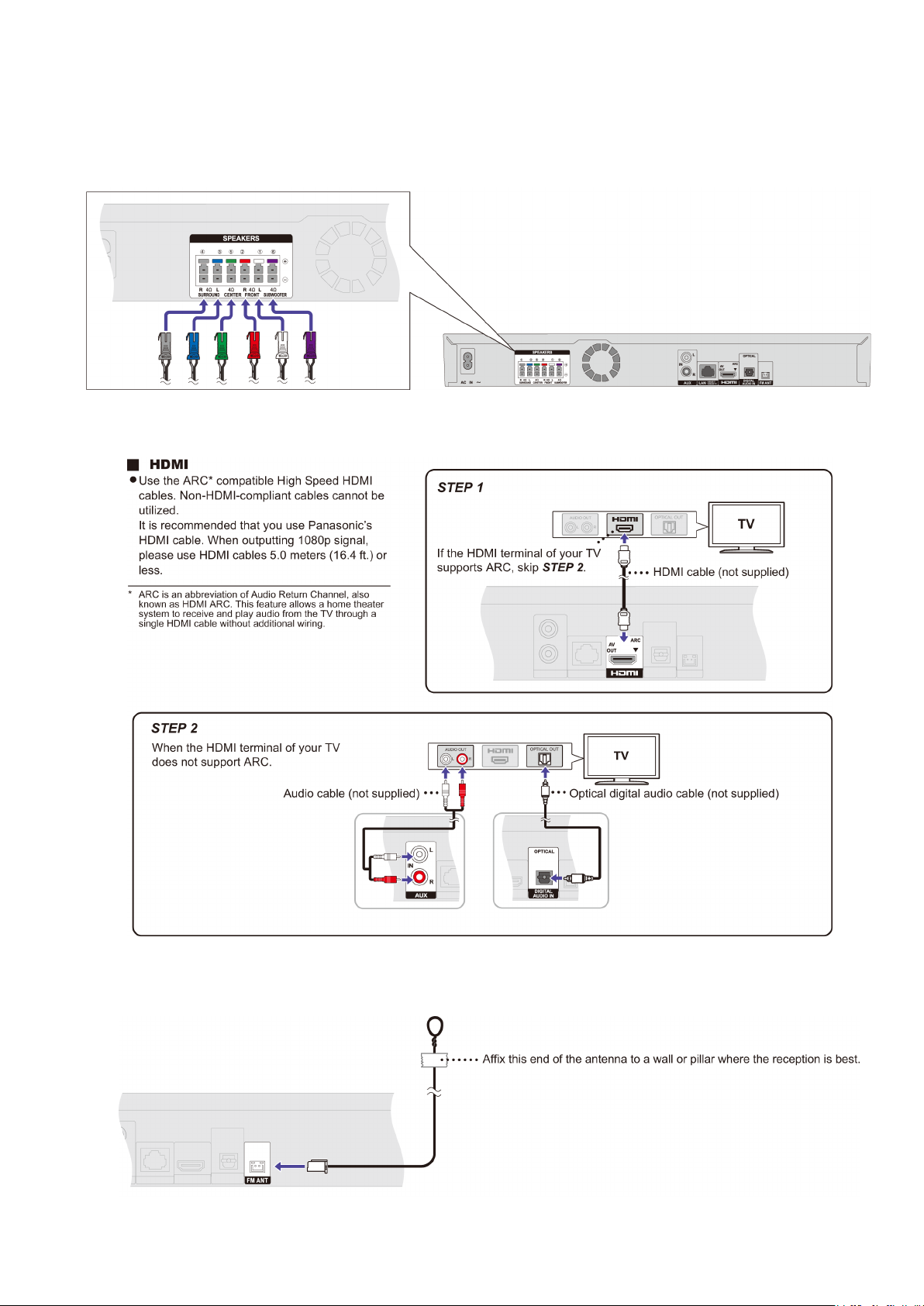
6 Installation Instructions
Turn off all equipment before connection and read the appropriate operating instructions.
Do not connect the AC power supply cord until all other connections are completed.
6.1. Speaker Connection
Connect the speaker cables to the terminals of the same color.
6.2. Connection to a TV
(Only Front /Subwoofer BTT105
)
6.3. FM Antenna Connection
15
 Loading...