

Panasonic SA-BT100EB, SA-BT100EG Service Manual
A
ORDER NO. MD0805005CE
Blu-ray Disc Home Theater Sound System
SA-BT100EB
SA-BT100EG
Colour
(K).......................Black Type
Specifications
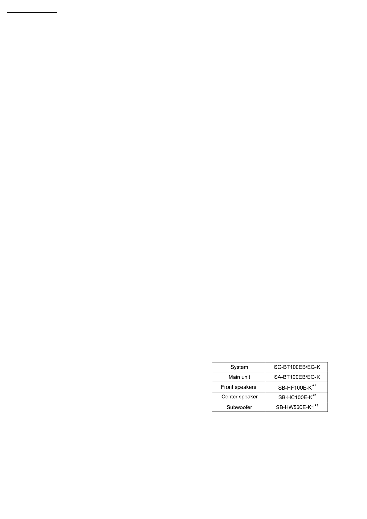
Main unit SA-BT100EB/EG
O
OGENERAL
OO
Power supply: 230V to 240V, 50 Hz
iPod connector: DC OUT 5V 500 mA MAX
Power consumption: This unit 140 W
Power consumption in standby mode:
approx. 0.4 W
Dimensions (W×H×D):
With transmitter:
430 mmx96 mmx327 mm
Without transmitter:
430 mmx90 mmx327 mm
Mass: This unit approx 4.1 kg(9.1 lbs)
Operating temperature range: +0 °C to +40 °C
Operating humidity range: 35% to 80% RH
(no condensation)
O
OAMPLIFIER SECTION
OO
RMS TTL Power Output:
1000W
Front Ch:
250 W per channel (6 Ω), 1 kHz, 10% THD
Center Ch:
250 W per channel (6 Ω), 1 kHz, 10% THD
Subwoofer Ch:
250 W per channel (6 Ω), 100 Hz, 10% THD
DIN TTL Power Output:
600W
Front Ch:
150 W per channel (6 Ω), 1kHz, 1.0% THD
Center Ch:
150 W per channel (6 Ω), 1kHz, 1.0% THD
Subwoofer Ch:
150 W per channel (6 Ω), 45 Hz to120 Hz, 1.0% THD
Audio Input:
UX:
x1
Digital Audio Input:
Optical:
x1
Sampling Frequency:
32kHz, 44.1kHz, 48kHz
Digital Audio output:
Optical:
© 2008 Matsushita Electric Industrial Co. Ltd.. All
rights reserved. Unauthorized copying and
distribution is a violation of law.
A
SA-BT100EB / SA-BT100EG
x1
O
OFM TUNER SECTION
OO
Frequency Range:
87.5-108.0 MHz (100-kHz step)
Antenna terminals
75 Ω (unbalanced)
O
ODISC SECTION
OO
Discs played:
(1) BD-Video:
BD-ROM Version 2
(2) BD-RE:
Version 3 (Single Layer, Dual Layer), JPEG
(3) BD-R:
Version 2 (Single Layer, Dual Layer)
(4) DVD-RAM:
DVD Video Recording format, AVCHD format*7, JPEG
(5) DVD-R/DVD-R DL:
DVD-Video format*1,DVD-Video Recording format, AVCHD
format
*1,7
DivX
(6) DVD-RW:
DVD-Video format*1,DVD-Video Recording format, AVCHD
format
*1,7
(7) +R/+RW/+R DL:
Video*1, AVCHD format
*1,7
(8) DVD-Video
DVD-Video format
(9) CD-Audio
CD-DA
(10) CD-R/RW
CD-DA, JPEG*5,MP3
Optical pick-up System with 2 lenses
Wavelength: 782 nm (CDs)/662nm
(DVDs)/405nm (BDs)
Laser Specification
System with 2 lenses
Class 1 LASER Product
Wavelength: 782 nm (CDs)/662 nm
(DVDs)/405 nm (BDs)
Laser power: No hazardous radiation is
emitted with the safety
protection
SD CARD SECTION
SD card slot: Output connector (1 system)
SD card: SD Memory Card*2formatted
FAT12, FAT32
*3
. JPEG*4,
AVCHD format
O
ODisable capacity will be less (SD Card)
OO
*1
Finalizing is necessary.
*2
includes SDHC card
includes miniSD cards (need a miniSD Adaptor)
includes microSD cards (need a microSD Adaptor)
*3
Does not support long file name
*4
The total combined maximum number of recognizable picture
contents and folders: 3000 picture contents and 300 folders.
*5
The total combined maximum number of recognizable picture
contents and folders: 999 picture contents and 99 folders.
*6
The total combined maximum number of recognizable picture
contents and folders: 9999 picture contents and 300 folders.
*7
The total combined maximum number of recognizable picture
contents and folders: 200 file contents and 300 folders.
*8
VCHD format V1.0
O
OVIDEO SECTION
OO
Signal system: PAL/NTSC
Video output
Output level: 1.0Vp-p(75Ω)
Output connector: Pin jack (1 system)
S Video Output
*6
Y Output level: 1.0Vp-p(75Ω)
C Output level: 0.286 Vp-p (75 Ω)atBurst
Output connector: S Terminal (1 system)
Component Video Output (1080i/720p/480p/480i)
*4
O
OY output level: 1.0Vp-p(75Ω)
OO
O
OPBoutput level: 0.7Vp-p(75Ω)
OO
O
OPRoutput level: 0.7Vp-p(75Ω)
OO
(1080i/720p/576p/576i)
Output connector Pin jack (Y: green, PB: blue, PR: red) (1
HDMI AV output
Output format:
480p (525p)/576p (625p)/720p (750p)/1080i (1225i)/1080p
Output connector:
Type A (19 pin)
HDMITM(Deep color)
O This unit supports “HDAVI Control 3” function.
Note:
1. Specifications are subject to change without notice.
Mass and dimensions are approximate.
2. Total harmonic distortion is measured by the digital spectrum
analyzer.
Solder:
This model uses lead free solder (PbF).
Mechanism:
This model uses BD/DVD Drive (VXY2001-SER)
Wireless Features:
This Model supports wireless surround (e.g:SH-FX67)
*7
Refer to their respective original service manuals for *1.
system)
(1125p)
2
SA-BT100EB / SA-BT100EG
CONTENTS
Page Page
1 Safety Precautions 6
1.1. GENERAL GUIDELINES
1.2. Before Repair and Adjustment
6
6
1.3. Protection Circuitry 6
1.4. Safety Parts Information
1.5. Caution for AC Cord
3
7
8

SA-BT100EB / SA-BT100EG
2 Prevention of Electrostatic Discharge (ESD) to
Electrostatically Sensitive (ES) Devices
3 Precaution of Laser Diode
4 About Lead Free Solder (PbF)
4.1. Service caution based on legal restrictions
5 Service Navigation
5.1. Service Information
6 Accessories
7 Operation Procedures
7.1. Remote Control Key Buttons Operations
7.2. Main Unit Key Buttons Operations
7.3. Using the VIERA Link “HDAVI Control™”
7.4. Using the iPod
7.5. Playing Secondary Video and Audio
7.6. Basic Connections
7.7. Disc and SD Cards Information
8 Operation Instructions
8.1. Taking out the Disc from BD/DVD Drive Unit when Disc
cannot be ejected by OPEN/CLOSE button
9 Service Mode
9.1. Self-Diagnosis and Special Mode Setting
9.2. Special Mode Setting
9.3. Service Mode at glance
9.4. Service Mode Table (Wireless - e.g. SH-FX67)
10 Assem bling an d Disas semb l ing
10.1. Disassembly Flow Chart
10.2. Main Components and P.C.B. Locations
10.3. Disassembly of Top Cabinet
10.4. Disassembly of Rear Panel
10.5. Disassembly of Front Panel
10.6. Disassembly of BD/DVD Drive Unit
10.7. Disassembly of Panel/ Headphone/ Power / Open/close
P.C.B.
10.8. Disassembly of SD P.C.B.
10.9. Disassembly of Lid
10.10. Disassembly of Ipod Cradle P.C.B.
10.11. Disassembly of AC Inlet P.C.B.
10.12. Disassembly of Main P.C.B.
10.13. Disassembly of D-Amp P.C.B.
10.14. Replacement of Digital Amp IC (IC5000)
10.15. Disassembly of SMPS P.C.B.
10.16. Replacement of Switch Regulator IC (IC5701)
10.17. Replacement of Switch Regulator Diode (D5702)
10.18. Replacement of Regulator Diode (D5801)
10.19. Replacement of Regulator Diode (D5802)
10.20. Replacement of Regulator Diode (D5803)
10.21. Disassembly of Wireless Adapter P.C.B.
10.22. Disassembly of DSP P.C.B.
10.23. Disassembly of Digital P.C.B.
10.24. Disassembly of S Video P.C.B.
10.25. Disassembly of Stand
11 Service Fixture and Tools
12 Service Position
12.1. Checking & Repairing Main P.C.B.
12.2. Checking & Repairing D-Amp P.C.B.
9
10
11
11
12
12
13
14
14
15
16
17
19
20
23
27
12.3. Checking & Repairing SMPS P.C.B.
12.4. Checking & Repairing DSP P.C.B.
12.5. Checking & Repairing Digital P.C.B.
13 Caution for Replacing Parts
13.1. Notice after replacing Digital P.C.B.
13.2. Items that should be done after replacing parts
13.3. Standard Inspection Specifications after Making Repairs
14 Vol tage and Waveform Chart
14.1. DSP P.C.B. (IC3001 ~ IC3004)
14.2. DSP P.C.B. (IC3101 ~ IC3104)
14.3. DSP P.C.B. (IC3201 ~ QR3601)
14.4. D-Amp P.C.B.
14.5. Main P.C.B. (IC100 ~ IC509)
14.6. Main P.C.B. (IC801 ~ QR7001)
14.7. S-Video P.C.B. (IC1501)
14.8. Panel P.C.B. (IC6001 ~ Q6003)
14.9. SMPS P.C.B. (IC5701 ~ QR5801)
27
28
28
31
33
38
40
42
43
44
44
44
45
14.10. Waveform Chart
15 Illustration of IC’s, Transistors and Diodes
16 Wiring Connection Diagram
17 Block Diagra m
17.1. Digital
17.2. IC Terminal (Digital) Chart
17.3. Digital P.C.B. Regulator
17.4. DSP
17.5. IC Terminal (DSP) Chart
17.6. System Control
17.7. Video
17.8. Audio Selector
17.9. Audio
17.10. Digital Audio Amp
46
47
47
48
49
50
51
52
52
53
54
55
56
57
58
58
59
60
61
62
63
63
17.11. Power
18 Schem atic Diagram Notes
19 Schematic Diagram
19.1. Digital Circuit
19.2. DSP Circuit
19.3. Main Circuit
19.4. Panel, Power Button, Open/Close Circuit
19.5. Headphone, SD, Wireless Adapter, Ipod Cradle Circuit
19.6. D-Amp Circuit
19.7. SMPS Circuit
19.8. AC Inlet & S-Video Circuit
20 Prin ted Circuit Board
20.1. Digital P.C.B.
20.2. DSP P.C.B.
20.3. Main P.C.B.
20.4. Panel, Power Button, Open/Close, Headphone, SD P.C.B.
20.5. Wireless Adapter, Ipod Cradle, AC Inlet, S-Video P.C.B.
20.6. D-Amp P.C.B.
20.7. SMPS P.C.B.
21 Basic Troubleshoo ting Guide
63
65
66
67
71
71
71
71
72
72
73
74
75
76
77
78
78
78
79
81
83
85
85
86
88
89
90
92
93
94
95
96
97
99
101
101
117
123
129
130
131
133
135
137
137
138
139
140
141
142
143
145
4

SA-BT100EB / SA-BT100EG
21.1. Troubleshooting Guide for F61 and/or F76 145
22 Terminal Function of IC’s
22.1. IC1103 (MFI341S2095): IC COPROCESSOR
22.2. IC6001(C0HBB0000057): IC FL Driver
23 Expl od ed View s
151
151
151
153
23.1. Cabinet Parts Location
23.2. Packaging
24 Repl acement Parts List
24.1. Component Parts List
25 Schem atic Diagra m for printing with letter size
153
155
157
158
179
5
SA-BT100EB / SA-BT100EG
1 Safety Precautions
1.1. GENERAL GUIDELINES
1. When servicing, observe the original lead dress. If a short circuit is found, replace all parts which have been overheated or
damaged by the short circuit.
2. After servicing, see to it that all the protective devices such as insulation barriers, insulation papers shields are properly
installed.
3. After servicing, carry out the following leakage current checks to prevent the customer from being exposed to shock hazards.
1.1.1. LEAKAGE CURRENT COLD CHECK
1. Unplug the AC cord and connect a jumper between the two prongs on the plug.
2. Measure the resistance value, with an ohmmeter, between the jumpered AC plug and each exposed metallic cabinet part on
the equipment such as screwheads, connectors, control shafts, etc. When the exposed metallic part has a r eturn path to the
chassis, the reading should be between 1MΩ and 5.2MΩ.
When the exposed metal does not have a return path to the chassis, the reading must be
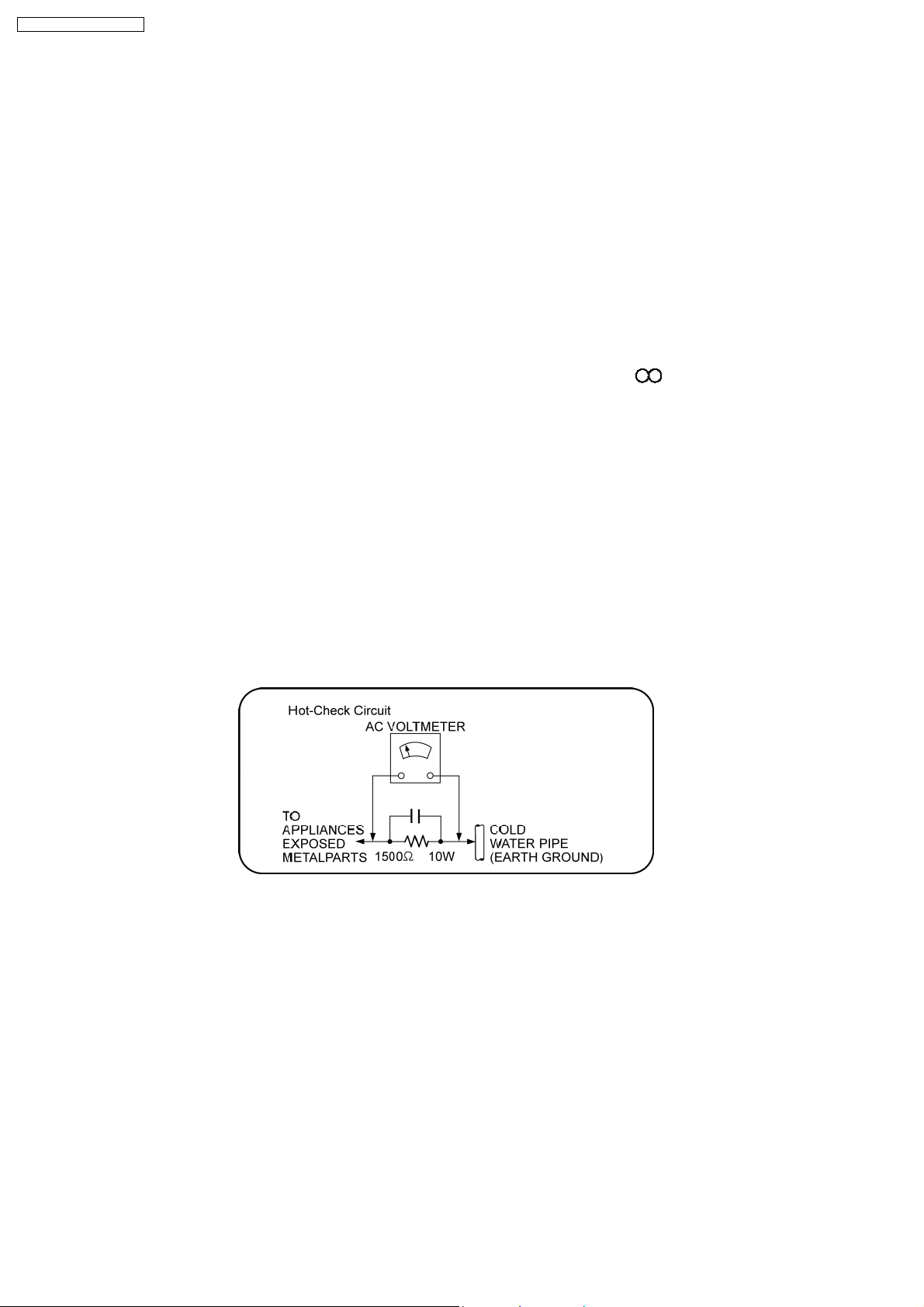
1.1.2. LEAKAGE CURRENT HOT CHECK
1. Plug the AC cord directly into the AC outlet. Do not use an isolation transformer for this check.
2. Connect a 1.5kΩ, 10 watts resistor, in parallel with a 0.15µF capacitors, between each exposed metallic part on the set and a
good earth ground such as a water pipe, as shown in Figure 1.
3. Use an AC voltmeter, with 1000 ohms/volt or more sensitivity, to measure the potential across the resistor.
4. Check each exposed metallic part, and measure the voltage at each point.
5. Reverse the AC plug in the AC outlet and repeat each of the above measurements.
6. The potential at any point should not exceed 0.75 volts RMS. A leakage current tester (Simpson Model 229 or equivalent) may
be used to make the hot checks, leakage current must not exceed 1/2 milliamp. In case a measurement is outside of the limits
specified, there is a possibility of a shock hazard, and the equipment should be repaired and rechecked before it is returned to
the customer.
Figure 1
1.2. Before Repair and Adjustment
Disconnect AC power to discharge unit AC Capacitors as such C5700, C5701, C5702, C5703, C5704 through a 10 Ω,10W
resistor to ground.
Caution:
DO NOT SHORT-CIRCUIT DIRECTLY (with a screwdriver blade, for instance), as this may destroy solid state devices.
After repairs are completed, restore power gradually using a variac, to avoid overcurrent.
Current consumption at AC 230-240 V, 50 Hz in NO SIGNAL mode volume minimal should be ~ 450 mA (For EB only).
Current consumption at AC 230 V, 50 Hz in NO SIGNAL mode volume minimal should be ~ 450 mA (For EG only).
1.3. Protection Circuitry
The protection circuitry may have operated if either of the following conditions are noticed:
•
• No sound is heard when the power is turned on.
• •
•
• Sound stops during a performance.
• •
6
SA-BT100EB / SA-BT100EG
The function of this circuitry is to prevent circuitry damage if, for example, the positive and negative speaker connection wires are
“shorted”, or if speaker systems with an impedance less than the indicated rated impedance of the amplifier are used.
If this occurs, follow the procedure outlines below:
1. Turn off the power.
2. Determine the cause of the problem and correct it.
3. Turn on the power once again after one minute.
Note:
When the protection circuitry functions, the unit will not operate unless the power is first turned off and then on again.
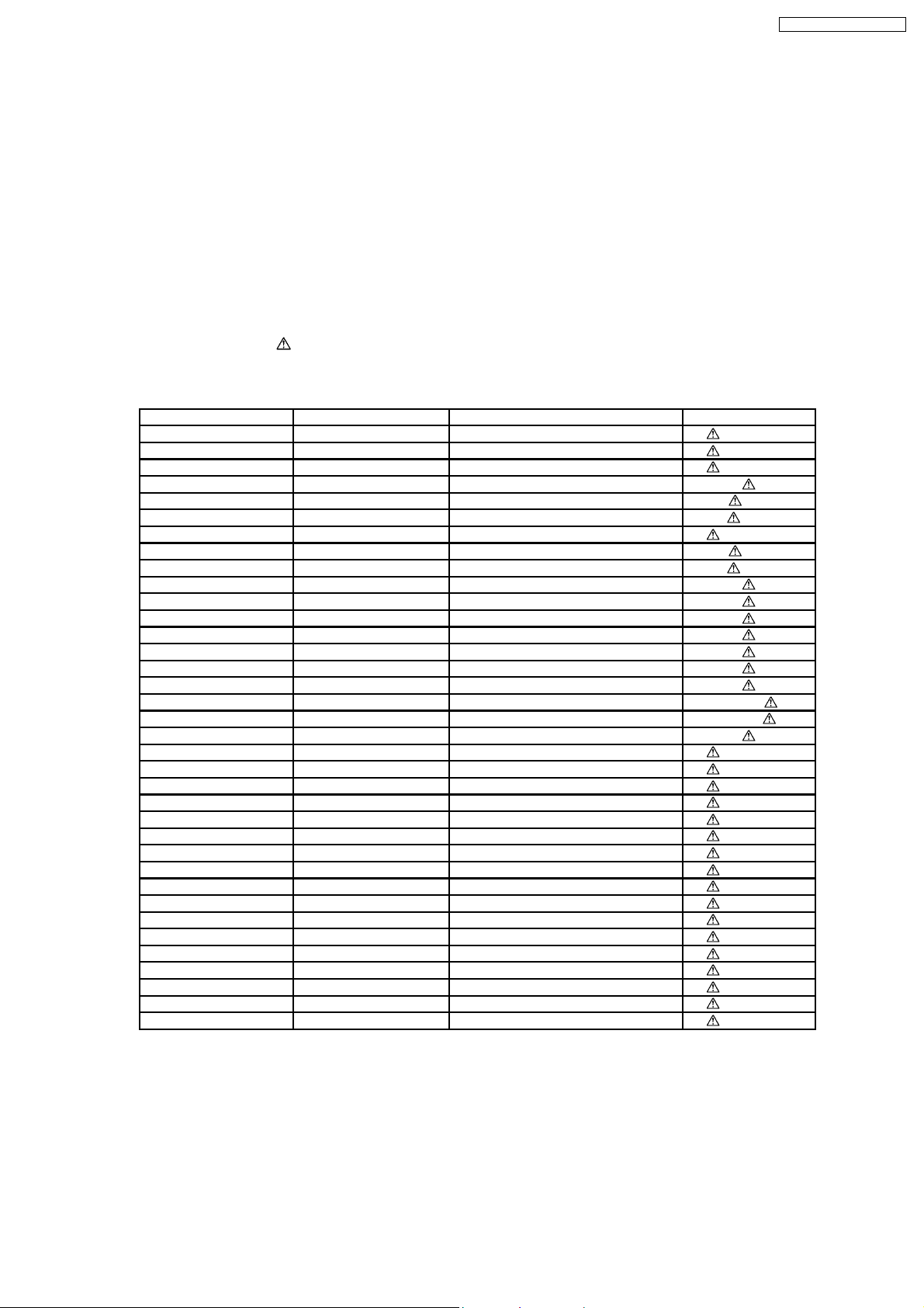
1.4. Safety Parts Information
Safety Parts List:
There are special components used in this equipment which are important for safety.
These parts are marked by
should be replaced with manufacturer’s specified parts to prevent shock, fire or other hazards.Do not modify the original design
without permission of manufacturer.
Ref. No. Part No. Part Name & Description Remarks
1 J0KD00000126 FERRITE CORE [M]
5 REXX0640-J BLACK WIRE [M]
6 REXX0641-J RED WIRE [M]
28 VXY2001-SER BD DRIVE UNIT [M] (RTL)
33 RGR0382B-A3 REAR PANEL [M] EG
33 RGR0382B-B2 REAR PANEL [M] EB
38 RKM0592-K TOP CABINET [M]
A2 K2CQ2CA00007 AC CORD [M] EG
A2 K2CT3CA00004 AC CORD [M] EB
PCB2 RFKB4368B DIGITAL PCB [M] (RTL)
PCB3 RFKB4370B MAIN PCB [M] (RTL)
PCB11 REPX0622W SMPS PCB [M] (RTL)
PCB12 REPX0622W AC INLET P.C.B [M] (RTL)
IC100 RFKWBT100EBK IC MICRO-PROCESSOR [M] (RTL)
IC103 RFKWEDF003EA IC EEPROM [M] (RTL)
IC3002 RFKWBT100DS1 IC FLASH ROM [M] (RTL)
IC3102 RFKWBT100DS3 IC FLASH ROM [M] (RTL) EG
IC3102 RFKWBT100DS4 IC FLASH ROM [M] (RTL) EB
IC51001 MN2WS0043AP IC DV LSI [M] (RTL)
DZ5701 ERZV10V511CS ZENER [M]
L5701 ELF15N035AN LINE FILTER [M]
L5702 ELF22V020A LINE FILTER [M]
L5703 ELF21N024A LINE FILTER [M]
T5701 ETS42BM1B6AC TRANSFORMER [M]
T5751 ETS19AB281AG BACK UP TRANSFORMER [M]
T7001 G4D1A0000117 SWITCHING TRANSFORMER [M]
PC5701 B3PBA0000402 PHOTO COUPLER [M]
PC5702 B3PBA0000402 PHOTO COUPLER [M]
PC5720 B3PBA0000402 PHOTO COUPLER [M]
PC5799 B3PBA0000402 PHOTO COUPLER [M]
F1 K5D402BK0007 FUSE [M]
IP7001 K5H7512A0010 PROTECTOR [M]
IP58301 ERBSE3R00U PROTECTOR [M]
TH5701 D4CAA5R10001 THERMISTOR [M]
TH5860 D4CC11040013 THERMISTOR [M]
P5701 K2AA2B000017 AC INLET [M]
in the Schematic Diagrams & Replacement Parts List. It is essential that these critical parts
Table 1
7
SA-BT100EB / SA-BT100EG
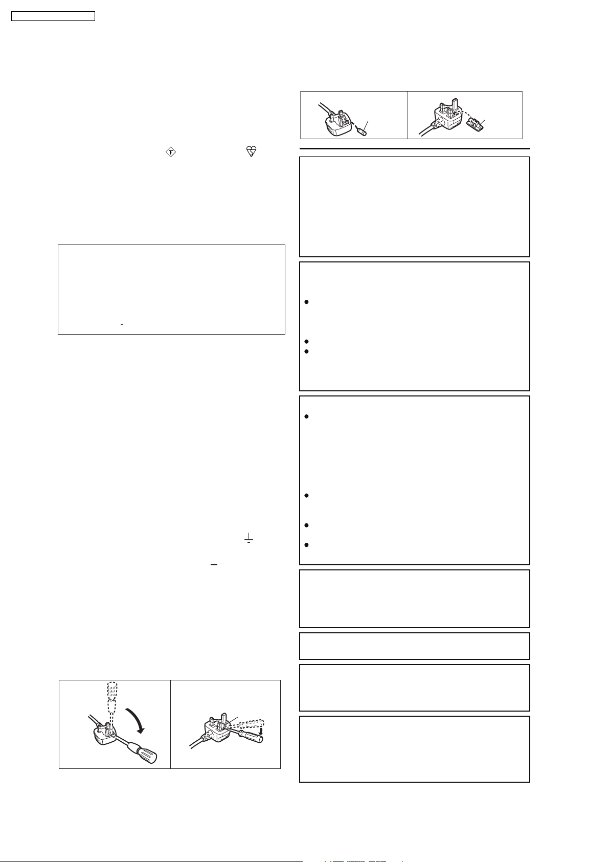
1.5. Caution for AC Cord
For your safety, please read the following text carefully.
This appliance is supplied with a moulded three pin
mains plug for your safety and convenience.
A 5-ampere fuse is fitted in this plug.
Should the fuse need to be replaced please ensure that
the replacement fuse has a rating of 5-ampere and that
it is approved by ASTA or BSI to BS1362.
Check for the ASTA mark or the BSI mark on the
body of the fuse.
If the plug contains a removable fuse cover you must
ensure that it is refitted when the fuse is replaced.
If you lose the fuse cover the plug must not be used
until a replacement cover is obtained.
A replacement fuse cover can be purchased from your
local dealer.
CAUTION!
IF THE FITTED MOULDED PLUG IS UNSUITABLE
FOR THE SOCKET OUTLET IN YOUR HOME THEN
THE FUSE SHOULD BE REMOVED AND THE
PLUG CUT OFF AND DISPOSED OF SAFELY.
THERE IS A DANGER OF SEVERE ELECTRICAL
SHOCK IF THE CUT OFF PLUG IS INSERTED
INTO ANY 13 AMPERE SOCKET.
If a new plug is to be fitted please observe the wiring
code as stated below.
If in any doubt please consult a qualified electrician.
IMPORTANT
The wires in this mains lead are coloured in accordance
with the following code:
Blue: Neutral, Brown: Live.
As these colours may not correspond with the coloured
markings identifying the terminals in your plug, proceed
as follows:
The wire which is coloured Blue must be connected to
the terminal which is marked with the letter N or
coloured Black or Blue.
The wire which is coloured Brown must be connected to
the terminal which is marked with the letter L or
coloured Brown or Red.
WARNING: DO NOT CONNECT EITHER WIRE TO
THE EARTH TERMINAL WHICH IS MARKED WITH
THE LETTER E, BY THE EARTH SYMBOL OR
COLOURED GREEN OR GREEN/YELLOW.
THIS PLUG IS NOT WATERPROOF KEEP DRY.
Before use
Remove the connector cover.
How to replace the fuse
The location of the fuse differ according to the type of
AC mains plug (figures A and B). Confirm the AC mains
plug fitted and follow the instructions below.
Illustrations may differ from actual AC mains plug.
A A
2. Replace the fuse and close or attach the fuse cover.
Figure A
Fuse
(5 ampere)
Figure B
Fuse
(5 ampere)
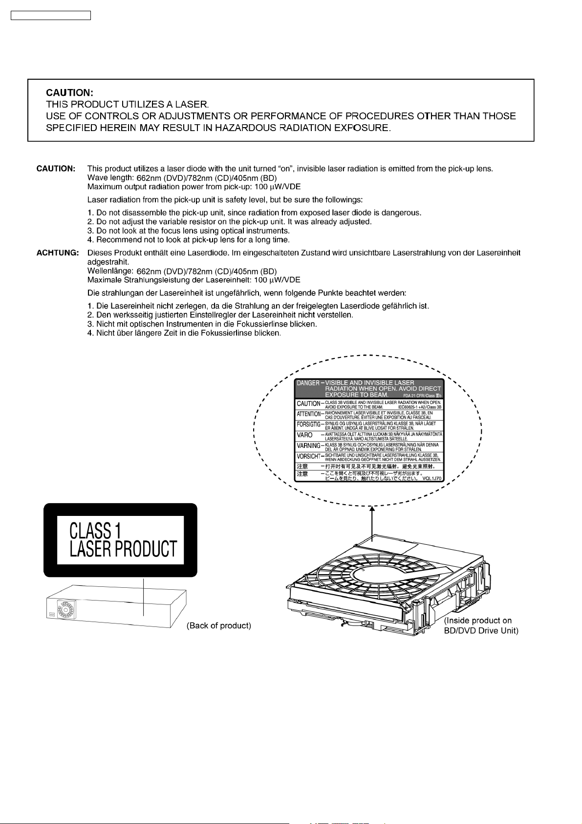
CAUTION!
THIS PRODUCT UTILIZES A LASER.
USE OF CONTROLS OR ADJUSTMENTS OR
PERFORMANCE OF PROCEDURES OTHER THAN
THOSE SPECIFIED HEREIN MAY RESULT IN
HAZARDOUS RADIATION EXPOSURE.
DO NOT OPEN COVERS AND DO NOT REPAIR
YOURSELF. REFER SERVICING TO QUALIFIED
PERSONNEL.
WARNING:
TO REDUCE THE RISK OF FIRE, ELECTRIC
SHOCK OR PRODUCT DAMAGE,
DO NOT EXPOSE THIS APPARATUS TO RAIN,
MOISTURE, DRIPPING OR SPLASHING AND THAT
NO OBJECTS FILLED WITH LIQUIDS, SUCH AS
VASES, SHALL BE PLACED ON THE APPARATUS.
USE ONLY THE RECOMMENDED ACCESSORIES.
DO NOT REMOVE THE COVER (OR BACK);
THERE ARE NO USER SERVICEABLE PARTS
INSIDE. REFER SERVICING TO QUALIFIED
SERVICE PERSONNEL.
CAUTION!
DO NOT INSTALL OR PLACE THIS UNIT IN A
BOOKCASE, BUILT-IN CABINET OR IN
ANOTHER CONFINED SPACE. ENSURE THE
UNIT IS WELL VENTILATED. TO PREVENT RISK
OF ELECTRIC SHOCK OR FIRE HAZARD DUE
TO OVERHEATING, ENSURE THAT CURTAINS
AND ANY OTHER MATERIALS DO NOT
OBSTRUCT THE VENTILATION VENTS.
DO NOT OBSTRUCT THE UNIT S VENTILATION
OPENINGS WITH NEWSPAPERS, TABLECLOTHS,
CURTAINS, AND SIMILAR ITEMS.
DO NOT PLACE SOURCES OF NAKED FLAMES,
SUCH AS LIGHTED CANDLES, ON THE UNIT.
DISPOSE OF BATTERIES IN AN
ENVIRONMENTALLY FRIENDLY MANNER.
CAUTION
Danger of explosion if battery is incorrectly replaced.
Replace only with the same or equivalent type
recommended by the manufacturer. Dispose of used
batteries according to the manufacturer s instructions.
THIS UNIT IS INTENDED FOR USE IN MODERATE
CLIMATES.
1. Open the fuse cover with a screwdriver.
Figure A Figure B
Fuse cover
This product may receive radio interference caused
by mobile telephones during use. If such interference
is apparent, please increase separation between the
product and the mobile telephone.
The socket outlet shall be installed near the
equipment and easily accessible. The mains plug of
the power supply cord shall remain readily operable.
To completely disconnect this apparatus from the AC
Mains, disconnect the power supply cord plug from
AC receptacle.
8

SA-BT100EB / SA-BT100EG
2 Prevention of Electrostatic Discharge (ESD) to
Electrostatically Sensitive (ES) Devices
Some semiconductor (solid state) devices can be damaged easily by static electricity. Such components commonly are called
Electrostatically Sensitive (ES) Devices. Examples of typical ES devices are integrated circuits and some field-effect transistors and
semiconductor “chip” components. The following techniques should be used to help reduce the incidence of component damage
caused by electrostatic discharge (ESD).
1. Immediately before handling any semiconductor component or semiconductor-equipped assembly, drain off any ESD on your
body by touching a k nown earth ground. Alternatively, obtain and wear a commercially available discharging ESD wrist strap,
which should be removed for potential shock reasons prior to applying power to the unit under test.
2. After removing an electrical assembly equipped with ES devices, place the assembly on a conductive surface such as
aluminum foil, to prevent electrostatic c harge buildup or exposure of the assembly.
3. Use only a grounded-tip soldering iron to solder or unsolder ES devices.
4. Use only an anti-static solder removal device. Some solder removal devices not classified as “anti-static (ESD protected)” can
generate electrical charge sufficient to damage ES devices.
5. Do not use freon-propelled chemicals. These can generate electrical charges sufficient to damage ES devices.
6. Do not remove a replacement ES device from its protective package until immediately before you are ready to install it. (Most
replacement ES devices are packaged with leads electrically shorted together by conductive foam, aluminum foil or comparable
conductive material).
7. Immediately before removing the protective material from the leads of a replacement ES device, touch the protective material
to the chassis or circuit assembly into which the device will be installed.
Caution:
Be sure no power is applied to the chassis or circuit, and observe all other safety precautions.
8. Minimize bodily motions when handling unpackaged replacement ES devices. (Otherwise harmless motion such as the
brushing together of your clothes fabric or the lifting of your foot from a carpeted floor can generate static electricity (ESD)
sufficient to damage an ES device).
9
SA-BT100EB / SA-BT100EG
3 Precaution of Laser Diode
10
SA-BT100EB / SA-BT100EG
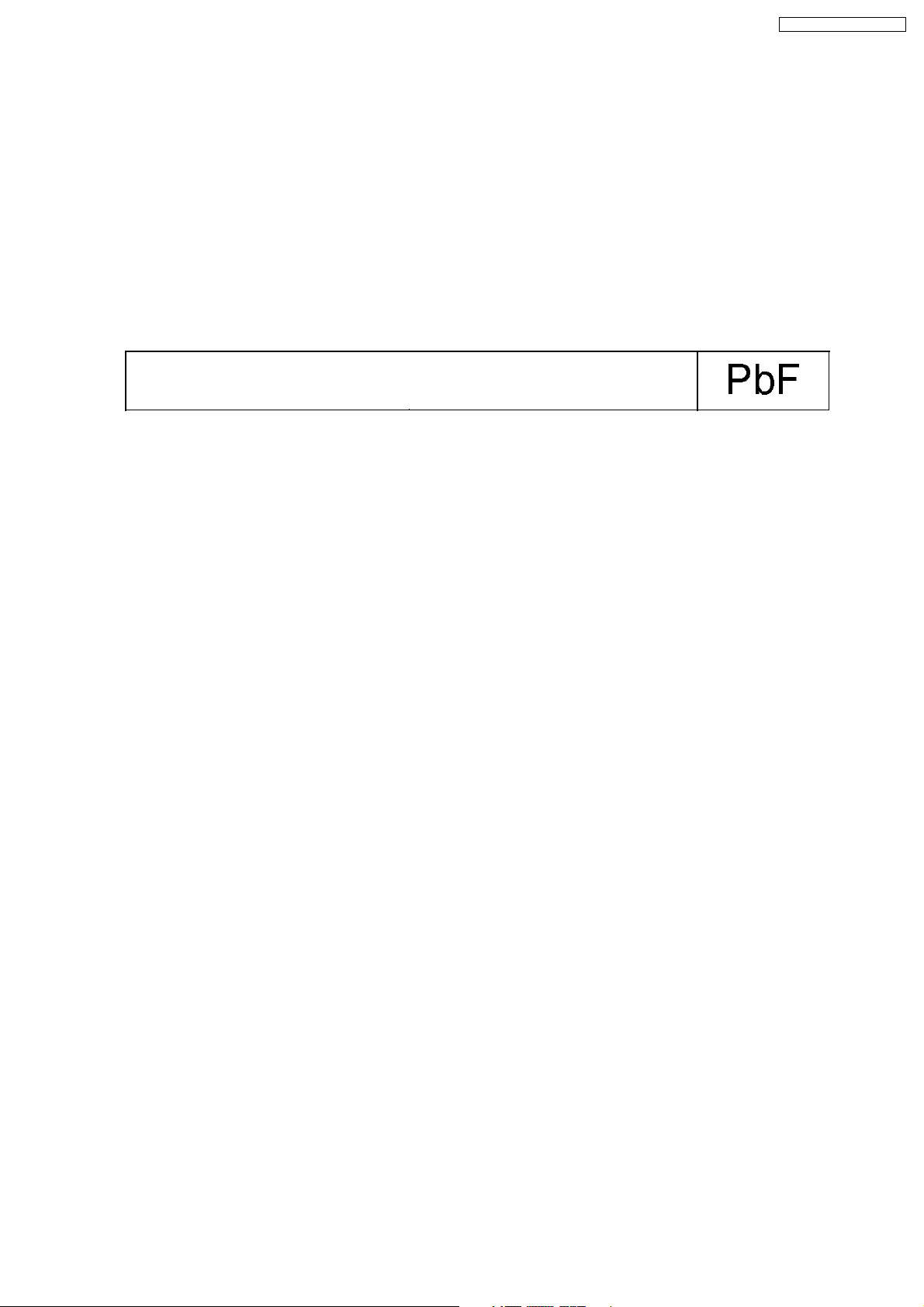
4 About Lead Free Solder (PbF)
4.1. Service caution based on legal restrictions
4.1.1. General description about Lead Free Solder (PbF)
The lead free solder has been used in the mounting process of all electrical components on the printed circuit boards used for this
equipment in considering the globally environmental conservation.
The normal solder is the alloy of tin (Sn) and lead (Pb). On the other hand, the lead free solder is the alloy mainly consists of tin
(Sn), silver (Ag) and Copper (Cu), and the melting point of the lead free solder is higher approx.30 degrees C (86°F) more than that
of the normal solder.
Definition of PCB Lead Free Solder being used
The letter of “PbF” is printed either foil side or components side on the PCB using the lead free solder.
(See right figure)
Service caution for repair work using Lead Free Solder (PbF)
•
• The lead free solder has to be used when repairing the equipment for which the lead free solder is used.
• •
(Definition: The letter of “PbF” is printed on the PCB using the lead free solder.)
•
• To put lead free solder, it should be well molten and mixed with the original lead free solder.
• •
•
• Remove the remaining lead free solder on the PCB cleanly for soldering of the new IC.
• •
•
• Since the melting point of the lead free solder is higher than that of the normal lead solder, it takes the longer time to melt
• •
the lead free solder.
•
• Use the soldering iron (more than 70W) equipped with the temperature control after setting the temperature at 350±30
• •
degrees C (662±86°F).
Recommended Lead Free Solder (Service Parts Route.)
•
• The following 3 types of lead free solder are available through the service parts route.
• •
RFKZ03D01K-----------(0.3mm 100g Reel)
RFKZ06D01K-----------(0.6mm 100g Reel)
RFKZ10D01K-----------(1.0mm 100g Reel)
Note
* Ingredient: tin (Sn), 96.5%, silver (Ag) 3.0%, Copper (Cu) 0.5%, Cobalt (Co) / Germanium (Ge) 0.1 to 0.3%
11

SA-BT100EB / SA-BT100EG
5 Service Navigation
5.1. Service Information
The service manual contains technical information which will allow service personnel’s to understand
and service this model.
Please place orders using the parts list and not the drawing reference numbers.
If the circuit is changed or modified, the information will be followed by supplement service manual to be filed with
original service manual.
1) This service manual does not contain the following information, because of the impossibility of servicing at
component level.
* Schematic Diagram, Block Diagram and P.C.B. layout of Digital P.C.B..
* PArts List for individual parts of Digital P.C.B..
* Exploded View and Parts List for individual parts of BD/DVD drive.
2) The following category are recycle module part. Please send them to Central Repair Center.
* Digital P.C.B. (BT100EB/EG: RFKB4368B)
3) For BD/DVD Drive, it depends on area to different recycle system.
Please refer to service policy in detail.
* BD/DVD drive (VXY2001-SER)
12
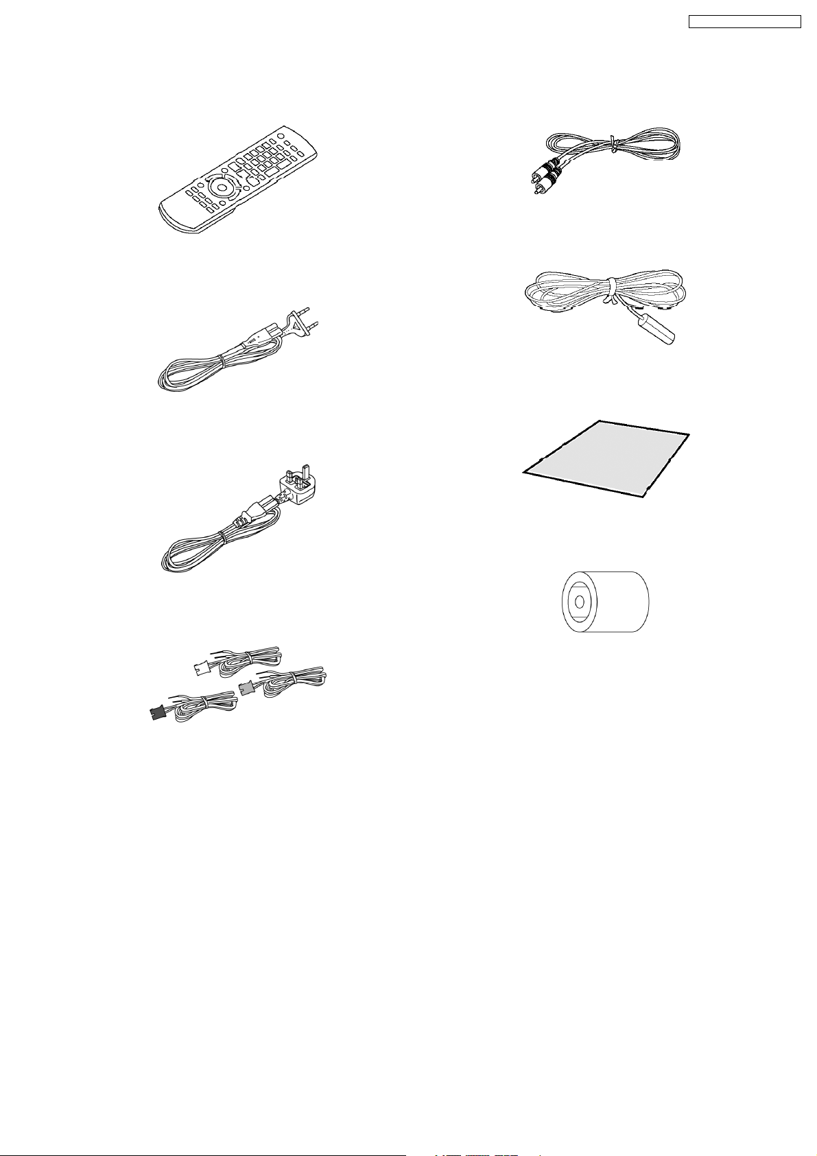
6 Accessories
•
• Note: Refer to “Replacement Parts List” (Section 25) for the part number.
• •
Remote control
AC Cord (EG)
SA-BT100EB / SA-BT100EG
Video cable
FM Indoor Antenna
AC Cord (EB)
Speaker cables
Speaker cable sticker
Antenna plug
adapter
13
SA-BT100EB / SA-BT100EG
7 Operation Procedures
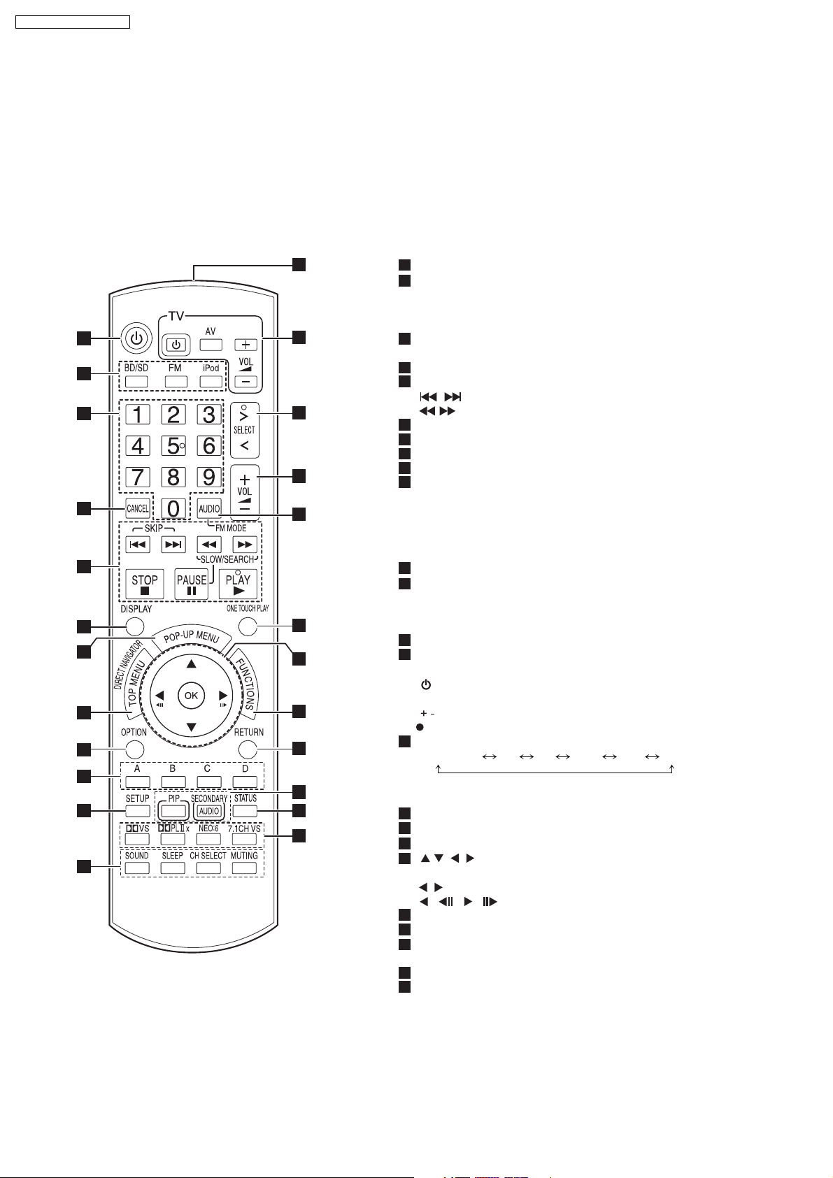
7.1. Remote Control Key Buttons Operations
Remote control
1
Turn the unit on and off
2
Select the source
[BD/SD]: Select disc drive or SD card drive
[FM]: Select FM tuner
[iPod]: Select iPod as the source
3
Numbered buttons
Select preset radio stations and title numbers, etc./Enter numbers
4
Cancel
5
Basic playback control buttons
[ , ]: Select preset radio stations
[ , ]: Select radio station manually
6
Show on-screen menu
7
Show Pop-up menu
8
Show Top Menu/Direct Navigator
9
Show option menu
10
These buttons are used when operating a BD-Video disc that
includes Java
operating this kind of disc, please read the instructions that came
with the disc.
The [A] and [B] buttons are also used with the "Title View", "Picture
View" and "Album View" screens
11
Show Setup menu
[SOUND]: Set the sound effect
12
[SLEEP]: Set the sleep timer
[CH SELECT]: Select speaker channel
[MUTING]: Mute the sound
13
Transmit the remote control signal
14
TV operation buttons
Aim the remote control at the Panasonic TV and press the button.
[ TV]: Turn the TV on and off
[AV]: Switch the input channel
[ VOL]: Adjust the TV volume
This may not work properly with some models.
15
Select the source
BD/DVD/CD SD FM IPOD D-IN AUX
"SD" on the unit’s display is not displayed when the
SD card is not in the SD card slot
16
Adjust the volume of the main unit
17
Select audio/remove interference during radio reception
Start up and play a disc automatically
18
[ , , , ]: Menu selection
19
[OK]: Selection
[ , ]: Select preset radio station
[ ] ( ),[ ] ( ): Frame-by-frame
20
Show FUNCTIONS menu
21
Return to previous screen
[PIP]:Switch on/off Secondary Video (Picture-in-picture)
22
[SECONDARY AUDIO]:Switch on/off Secondary Audio
23
Show status messages
24
Enjoy surround sound
[7.1CH VS]: Available when using a 5.1ch speaker system
10
11
12
13
1
2
3
4
5
6
7
8
9
14
15
16
17
18
19
20
21
22
23
24
TM
applications (BD-J). For more information about
14
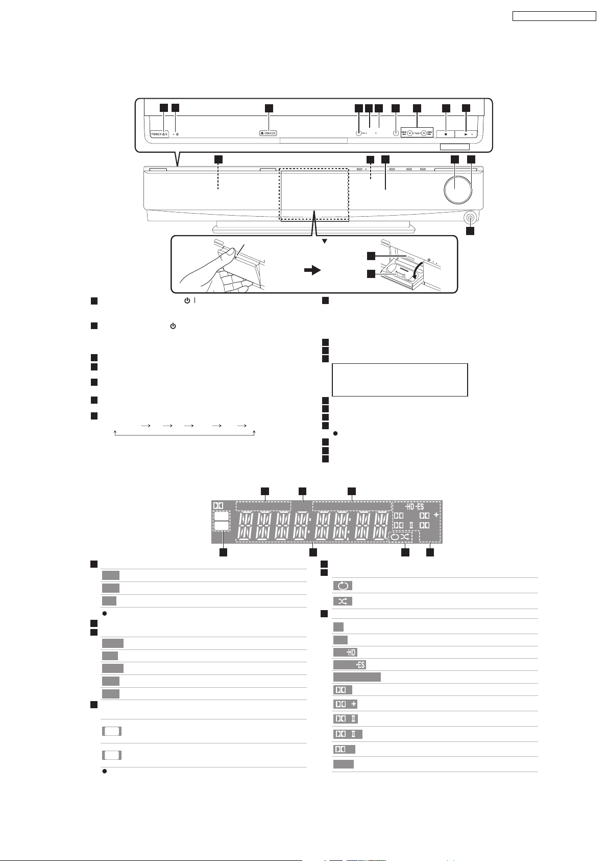
7.2. Main Unit Key Buttons Operations
Main unit
SA-BT100EB / SA-BT100EG
1 2
11 12 13 14 15
1
POWER button (POWER / )
Press to switch the unit from on to standby mode or vice versa. In
standby mode, the unit is still consuming a small amount of power.
2
Standby/on indicator ( )
When the unit is connected to the AC mains supply, this
indicator lights up in standby mode and goes out when the unit is
turned on.
3
Open or close the disc tray
4
SW BOOST (Subwoofer boost) button
Turn Subwoofer boost on/off
5
SW BOOST (Subwoofer boost) indicator
Lights when Subwoofer boost is on
6
7.1CH D.S.P. indicator
Illuminated during 7.1ch source playback.
7
Select the source
BD/DVD/CD SD FM IPOD D-IN AUX
"SD" on the unit’s display is not displayed when the
SD card is not in the SD card slot.
3 4 5 6 8 9 10
Place your finger on the section
and open it diagonally downwards.
7
7.1CH
SW
SELECTOR
D.S.P.
BOOST
16
17
8
Select the radio station manually
Search /Slow-motion/Skip
Search: Press and hold (During play)
Slow-motion: Press and hold (During pause)
Skip: Press
9
Stop
10
Start play
11
Disc tray
CAUTION
Do not place objects in front of the unit.
The disc ray may collide with objects when
it is opened, and this may cause injury.
12
Remote control signal sensor
13
Display
14
Adjust the volume of the main unit
15
Volume indicator
It is possible to set the indicator to turn on/off.
16
SD card slot
17
Connect iPod
18
Headphone terminal
18
Rear panel terminals
The unit’s display
VS
DISC
W2S
W4S
4 5 6 7
1
Drive indicator
Lights when disc is ready to play.
DISC
Lights when iPod is ready to play.
iPod
Lights when SD card is ready to play.
SD
The indicator blinks when reading data.
2
SLEEP indicator
3
Radio broadcast display
Lights when receiving a radio broadcast.
TUNED
Lights when RDS is available.
RDS
Lights when set to monaural reception.
MONO
Lights when set to stereo broadcast reception.
ST
Flashes during preset channel registration.
M
4
Wireless link indicator
(when using the optional wireless accessory: SH-FX67)
Lights when speaker setting is set to 5.1ch and
W2S
link with wireless system is activated.
Lights when speaker setting is set to 7.1ch and
W4S
link with wireless system is activated.
The indicator blinks when the wireless link is inactive for
a long time.
1 2 3
TUNED RDS
SLP
SD
iPod
5
Main display section
6
iPod indicator
7
Audio signal indicator
VS
DTS
DTS
DTS
DTS
NEO:6
MONO
ST M
DTS
96/24
DD
PLxHD
NEO:6
Illuminated during iPod repeat playback
Illuminated during iPod shuffle playback
Lights when Dolby Virtual speaker function is
being used.
Lights when DTS decoder is being used.
Lights when DTS-HD decoder is being used.
Lights when DTS-ES decoder is being used.
Lights when DTS 96/24 decoder is being used.
96/24
D
D
PL
PL
HD
Lights when Dolby Digital decoder is being used.
Lights when Dolby Digital Plus decoder is
being used.
Lights when Dolby Pro Logic II decoder is
being used.
Lights when Dolby Pro Logic IIx decoder is
x
being used.
Lights when Dolby TrueHD decoder is
being used.
Lights when DTS NEO:6 matrix decoder is
being used.
15
SA-BT100EB / SA-BT100EG
7.3. Using the VIERA Link “HDAVI Control™”
(VIERA LinkTM H DAVI ControlTM)
What is VIERA Link HDAVI Control ?
VIERA Link HDAVI Control is a convenient function that offers linked
operations of this unit, and a Panasonic TV (VIERA) under HDAVI
Control . You can use this function by connecting the equipment with an
HDMI cable. See the operating instructions for connected equipment for
operational details.
Preparation
1
Confirm that the HDMI connection has been made
2
Set VIERA Link to On
3
To complete and activate the connection correctly, turn on all VIERA Link
HDAVI Control compatible equipment and set the TV to the corresponding
HDMI input mode for this unit.
Setting the TV audio for VIERA Link HD AVI Control
Select between AUX and D-IN to work with the linked operations. Confirm
the audio connection to the AUX terminal (for AUX ) or OPTICAL IN terminal
(for D-IN )
1
Press [ , SELECT] to select AUX or D-IN .
2
Press [SETUP].
3
(When D-IN is selected)
Press [ , ] to select TV SOUND .
4
Press [OK].
5
Press [ ] to switch
Whenever the connection or settings are changed, reconfirm the points above.
,
AUX or D-IN and press [OK].
What you can do with HDAVI Control
NOTE
VIERA Link HDAVI Control , based on the control
functions provided by HDMI which is an industry
standard known as HDMI CEC (Consumer
Electronics Control), is a unique function that we
have developed and added. As such, its operation
with other manufacturers equipment that supports
HDMI CEC cannot be guaranteed.
This unit supports HDAVI Control 3 function.
HDAVI Control 3 is the newest standard (current as
of December, 2007) for Panasonics HDAVI Control
compatible equipment. This standard is compatible
with Panasonics conventional HDAVI equipment.
Please refer to individual manuals for other
manufacturers equipment supporting VIERA Link
function.
It is recommended that you use Panasonic s
HDMI cable.
Recommended part number:
RP-CDHG10 (1.0 m), RP-CDHG15 (1.5 m)
RP-CDHG20 (2.0 m), RP-CDHG30 (3.0 m)
RP-CDHG50 (5.0 m), etc.
Non-HDMI-compliant cables cannot be utilized.
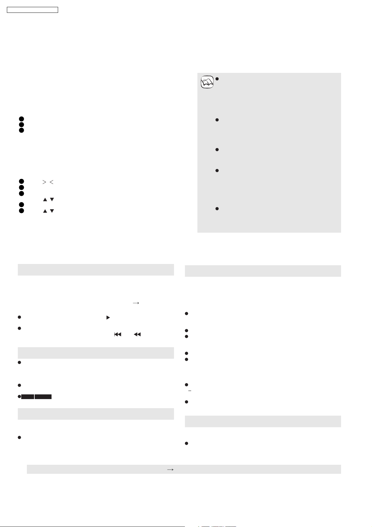
One touch play
You can turn on this unit and TV, and start playing with a single press
of a button.
Press [ONE TOUCH PLAY].
This unit s speakers will be automatically activated ( right, Speaker
control).
This function also works if you press [ ] (PLAY) on this units
remote control when this unit is in standby mode.
Playback may not be immediately displayed on the TV. If you miss
the beginning portion of playback, press [ ] or [ ] to go back to
where playback started.
Automatic input switching
When you switch the TV input to TV tuner mode, this unit will
automatically switch to AUX *
[This function does not work when the iPod selector (SIMPLE mode)
is chosen.]
When you start disc play, the TV will automatically switch its input
mode for this unit.
BD-V DVD-V when playback stops, the TV will automatically
return to TV tuner mode.
or D-IN * .
Automatic lip-sync function (for HDAVI Control 3)
Delay between audio and video is automatically adjusted, enabling
you to enjoy smooth audio for the picture
This function works only when BD/DVD/CD , SD , AUX * or D-IN *
is selected as the source on this unit.
Speaker control
You can select whether audio is output from the units speakers or the
TV speakers by using the TV menu settings. For details, refer to the
operating instructions of your TV.
Home Cinema
This unit s speakers are active.
When this unit is in standby mode, changing the TV speakers to this
unit s speakers in the TV menu will automatically turn the unit on and
select AUX *
The TV speakers are automatically muted.
You can control the volume setting using the volume or mute button
on the TVs remote control. (The volume level is displayed on the
main unit s FL display.)
To cancel muting, you can also use the home theater remote control
If you turn off this unit, TV speakers will be automatically activated.
TV
TV speakers are active.
The volume of this unit is set to 0 .
This function works only when BD/DVD/CD , SD , AUX *
D-IN * is selected as the source on the home theater system.
Audio output is 2-channel audio.
or D-IN * as the source.
or
Power off link
When the TV is turned off, this unit goes into standby mode
automatically.
This function works only when BD/DVD/CD , SD , IPOD , AUX *
or D-IN * is selected as the source on this unit.
* AUX or D- IN works depending on the TV SOUND setting ( above, Setting the TV audio for VIERA Link HDAVI Control ).
16
7.4. Using the iPod
Preparation
To view videos/photos from the iPod.
Ensure the video connection to the VIDEO OUT terminal on this unit.
Operate the iPod menu to make the appropriate video/photo output settings for your TV.
To display the picture, turn on the TV and select the appropriate video input mode.
Before connecting/disconnecting the iPod, turn the main unit off or reduce the volume of the main unit to its minimum.
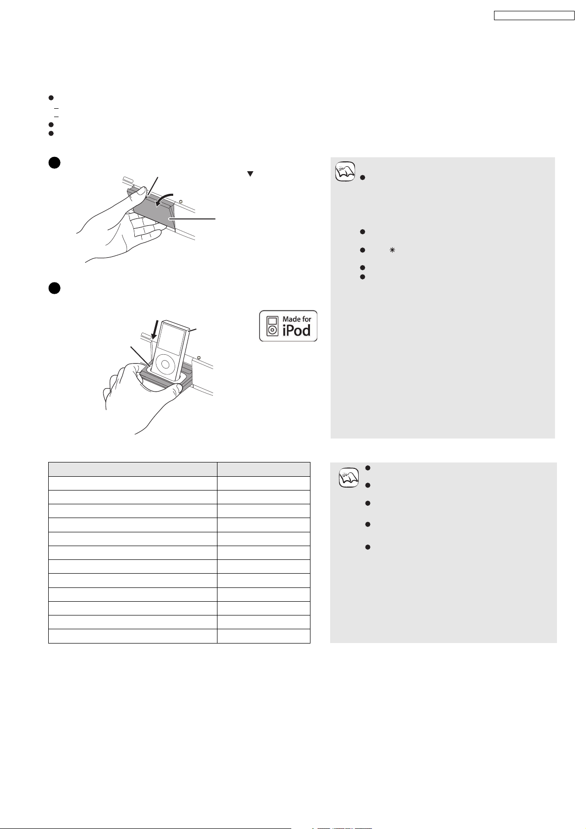
Open the Dock for iPod.
1
Place your finger on the section
and open it diagonally downwards.
Main unit
2
Connect the iPod (not included) firmly.
Recharging starts when the iPod is inserted.
e.g.,
iPod
Dock for iPod
About dock adapter
Attach the dock adapter which should be supplied
NOTE
with your iPod to the dock for the stable use of the
iPod. If you need an adapter, consult your iPod
dealer.
About recharging the battery
iPod will start recharging regardless of whether this
unit is on or off.
IPOD will be shown on the main unit s display
during iPod charging in main unit standby mode.
Check iPod to see if the battery is fully recharged.
If you are not using iPod for an extended period of
time after recharging has completed, disconnect it
from main unit, as the battery will be depleted
naturally. (Once fully recharged, additional
recharging will not occur.)
SA-BT100EB / SA-BT100EG
Dock adapter
(not included)
Main unit
Hold the dock when connecting/
disconnecting the iPod.
Compatible iPod
Name Memory size Compatibility depends on the software version of
iPod touch 8 GB, 16 GB
iPod nano 3rd generation (video) 4 GB, 8 GB
iPod classic 80 GB, 160 GB
iPod nano 2nd generation (aluminum) 2 GB, 4 GB, 8 GB
iPod 5th generation (video) 60 GB, 80 GB
iPod 5th generation (video) 30 GB
iPod nano 1st generation 1 GB, 2 GB, 4 GB
iPod 4th generation (color display) 40 GB, 60 GB
iPod 4th generation (color display) 20 GB, 30 GB
iPod 4th generation 40 GB
iPod 4th generation 20 GB
iPod mini 4 GB, 6 GB
NOTE
your iPod.
Audio/video cannot be recorded or transmitted to
iPods via this system.
Panasonic makes no warranty over iPod data
management.
For more information, refer to the operating
instructions for iPod.
The contents of the operating instructions and
those displayed on iPod may differ partially, but this
will not fundamentally affect use of music
playback.
17

SA-BT100EB / SA-BT100EG
Playback
This system features two different iPod playback modes.
The first of these is EXTENDED mode, for playback of music contents. With this mode, the menu screen on the system can be used to search for
playlists and artist names, and to play music. The second mode is SIMPLE mode, which can be used for playback of three types of contents
music, photos, and videos. With this mode, simple operations such as play, stop, and search can be performed on the display of your iPod.
Enjoy music
Press [iPod] to select IPOD .
1
(EXTENDED mode)
The iPod automatically switches to this units display mode.
iPod Music menu appears on the TV.
If the menu screen is not displayed, press [SETUP].
MusiciPod
Playlists
Artists
Albums
Songs
Podcasts
Audiobooks
Playback Mode
OK
Items Selection/playback method
Playlists
Artists
Albums
Songs
Podcasts
Audiobooks
Playback
Mode*
Search from all playlists.
Search by artist name.
Search by album title.
Search from all songs registered on iPod.
Search by episode for radio programs
downloaded from iTunes store.
Search by title from audiobooks purchased from
iTunes store or audible.com.
Shuffl e
Off: Cancel
Songs: Play all songs on iPod in random order.
Albums: Play all songs on album in random
order.
is displayed on the units display when
Songs or Albums is selected.
Repeat
Off: Cancel
One: Play single song repeatedly.
All: Play all songs from selected item (e.g.,
Playlists, Albums, etc.) repeatedly.
is displayed on the units display when
One or All is selected.
*
Playback modes during connection/when disconnected
System may be operated in same playback mode as set with
iPod when connected. Playback may also be continued on iPod
with same settings as made on system after disconnection.
Enjoy videos/photos
(SIMPLE mode)
You can also play music using SIMPLE mode.
1
Press [iPod] to select IPOD .
2
Press [SETUP] to switch the iPod to its own
display mode.
Proceed operations through display of iPod.
If the iPod Music menu ( left) is displayed, press [SETUP].
SIMPLE will be shown on the main unit s display.
Switch the TV input to video in.
3
4
Play a slideshow or video on your iPod.
The picture will be displayed on your TV.
You can also use the remote control to operate iPod menu.
[ , ]: To navigate menu items
[OK]: To go to the next menu
[RETURN]: To return to the previous menu
Basic controls (For music and videos only)
Buttons Functions
[](PLAY)
[]
[]
[, ]
(Press and hold)
[, ]
You can enjoy surround sound effect when you press [
[NEO:6]
Play
Pause
Press [ ] (PLAY) to restart play.
Playback start position may not be
stored in memory in certain cases.
Skip
Search
PLIIx
] or
2
Press [ , ] to select an item and press [OK].
Play will start from the selected song if this operation is
repeated several times.
Press [RETURN] to return to the previous screen.
e.g.,
Album
Playing
position
Song
Artis
t
Playing condition
iPod
Good morning
Ronaldo
Happy days
2:43
45 of 1230
Pause
Skip
Play
Skip
RETURN
Clear/display iPod Music menu during playback.
Press [TOP MENU].
18

7.5. Playing Secondary Video and Audio
Playing secondary video (picture-in-picture) and secondary audio
SA-BT100EB / SA-BT100EG
Secondary video can be played from a disc compatible with the picture-in-picture
function.
For the playback method, refer to the instructions for the disc.
Secondary video
To turn on/off secondary video
Press [PIP].
Secondary video is played.
PiP ON is displayed.
Press the button to turn it ON and OFF.
To turn on/off audio with the secondary video
Press [SECONDARY AUDIO].
The secondary audio is played.
Secondary Audio ON is displayed.
Press the button to turn it ON and OFF.
Primary video
NOTE
Only the primary video is played during
search/slow-motion or frame-by-frame.
Frame-by-frame is not available for some
BD-Video discs that contain
picture-in-picture function.
When BD-Video Secondary Audio in
Sound menu is set to Off , seco ndary
audio will not be played even if
[SECONDARY AUDIO] is pressed. Please
check that BD-Video Secondary Audio is
set to On
19
SA-BT100EB / SA-BT100EG
7.6. Basic Connections
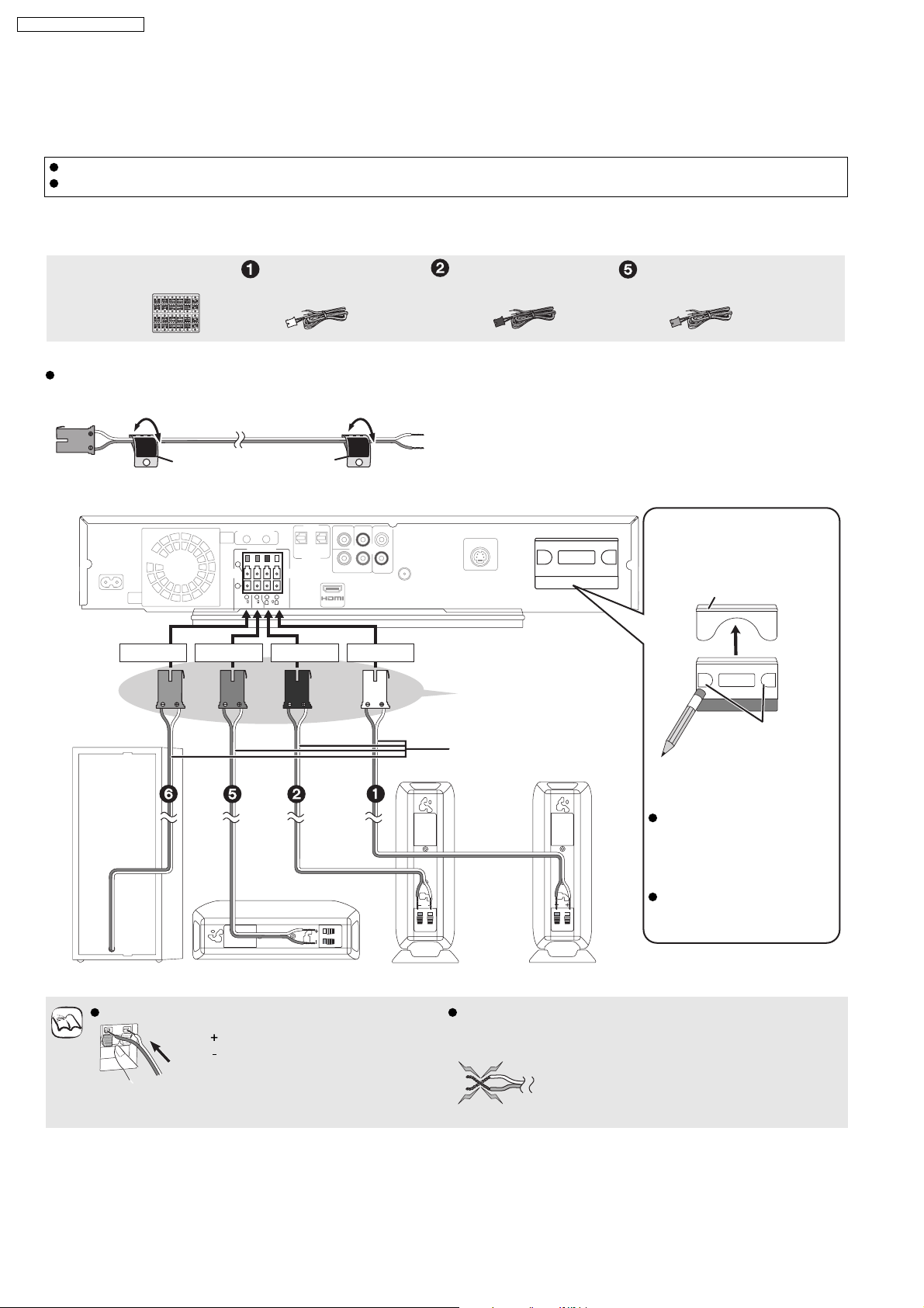
7.6.1. Speaker Cables and Transmitter Connection
Do not place the unit on amplifiers or equipment that may become hot. The heat can damage the unit.
Turn off all equipment before connection and read the appropriate operating instructions.
Speaker cables connection
Sheet of speaker cable
stickers
Speaker cable for front
speaker (L) (White)
Preparation
Attach the speaker cable stickers to make connection
easier.
e.g., Centre speaker
CENTER
5
WhiteRed
This unit
CENTER
5
Speaker cable sticker
(included)
GreenPurple
6
6
SUBWOOFER
SPEAKERS
5
CENTER
2
1
66
R
L
FRONT
Speaker cable for front
speaker (R) (Red)
DIGITAL
PUSH PUSH
TRANSMITTER
Connect to the terminals
of the same colour.
Speaker cable for
centre speaker (Green)
[When using the optional
wireless accessory:
SH-FX67]
Digital transmitter cover
PUSH PUSH
DIGITAL
PUSH PUSH
TRANSMITTER
Speaker cables (included)
Front
Center
Subwoofer Centre speaker Front speaker (R) Front speaker (L)
Insert the wires fully. Be careful not to cross (short-circuit) or reverse the
polarity of the speaker wires as doing so may damage
the speakers.
NOTE
: White
: Blue
Push!
Do not
Front
You can use the blunt
end of a writing
instrument to push
here until the cover
pops out.
Remove the digital
transmitter cover before
installing any optional
Panasonic wireless
accessory.
Replace the cover when the
digital transmitter is not in
use.
20
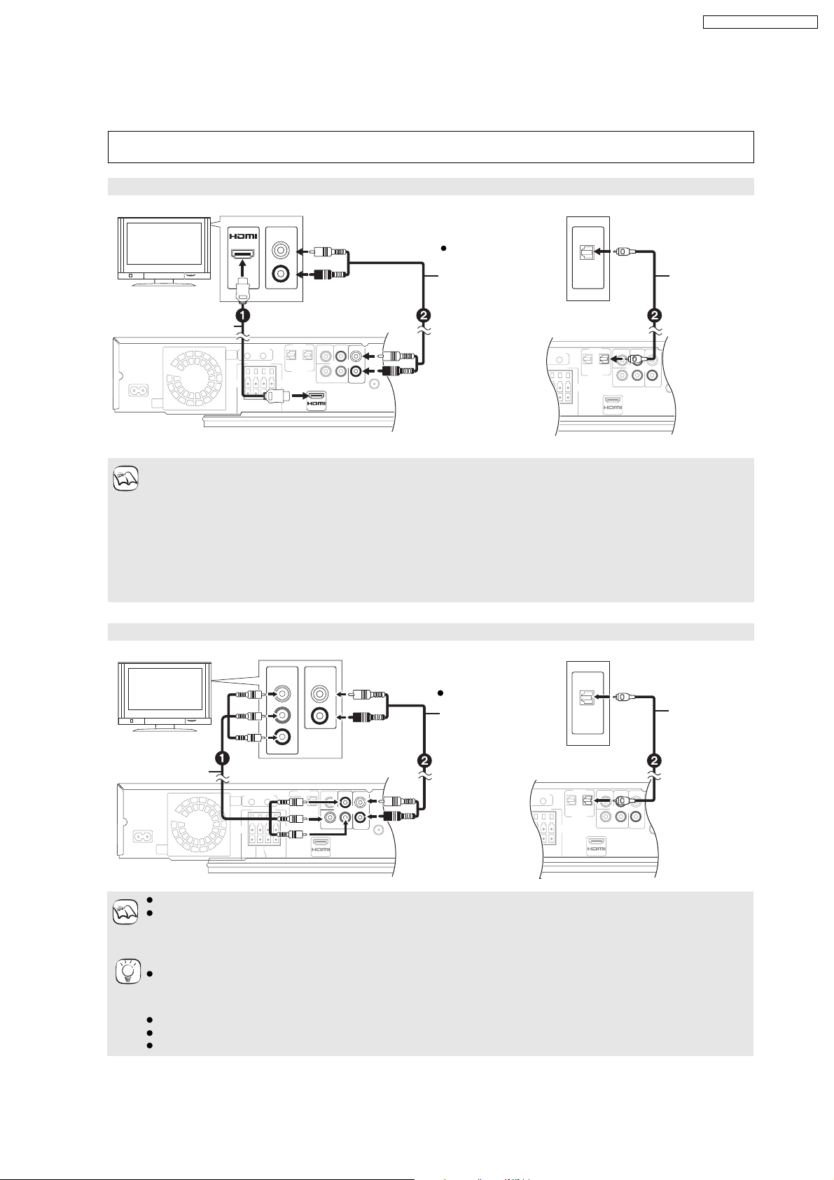
7.6.2. Connecting to a Television with HDMI & Video Cable
AV OUT
L
R
AUX
OPTICAL
DIGITAL
OUT
IN(TV)
COMPONENT
VIDEO OUT
Y
L
R
AUX
P
B
PR
OPTICAL
DIGITAL
OUT
IN(TV)
Connection to a TV
Do not connect through the video cassette recorder. Due to copy guard protection, the picture may not display
properly.
With an HDMI cable
SA-BT100EB / SA-BT100EG
*
OPTICAL
OUT
HDMI
compatible
TV
AV IN
AUDIO OUT
Audio cable
(not included)
L
The optical digital
audio cable can be
R
used when
connecting to the
TV with optical out
HDMI cable
terminals.
(not included)
This unit
Please use High Speed HDMI Cables that have the HDMI logo (as shown on the cover).
It is recommended that you use Panasonic s HDMI cable.
Recommended part number:
NOTE
RP-CDHG10 (1.0 m), RP-CDHG15 (1.5 m), RP-CDHG20 (2.0 m), RP-CDHG30 (3.0 m), RP-CDHG50 (5.0 m), etc.
When setting video output to 1080p please use HDMI cables 5.0 meters or less.
NECESSARY SETTINGS
HDMI Video Mode : On / HDMI Audio Output : "Off"
With this connection, you can use VIERA Link H DAVI Control
*
These audio connections will enable you to play audio from your TV through your home theater system
Optical
digital audio
*
cable
(not included)
Connection to a TV with component video cable
COMPONENT
AUDIO OUT
TV
Component
Video cable
(not included)
This unit
Connect terminals of the same colour.
The video output resolution is restricted to 576p/480p when DVD-Video, DivX and BD-Video discs recorded at a rate
NOTE
of 50 frames per second is output from the COMPONENT VIDEO OUT terminals.
*
These audio connections will enable you to play audio from your TV through your home theater system.
If you have a regular TV (CRT: cathode ray tube)
Progressive output may cause some flickering, even if it is progressive compatible. Turn off Progressive if you are
concerned about it. This is the same for multi system TV using PAL mode.
TIPS
To enjoy high definition/progressive video
Connect to a TV that supports 576p/480p or higher.
Set Component Resolution to 576p/480p , 7 20p or 1080 i .
Set HDMI Video Mode to Off . Otherwise, the video is output as 576i/480i.
VIDEO IN
Y
L
PB
R
P
R
Audio cable
*
(not included)
The optical digital
audio cable can be
used when
connecting to the
TV with optical out
terminals.
OPTICAL
OUT
Optical digital
audio cable
*
(not included)
21
SA-BT100EB / SA-BT100EG
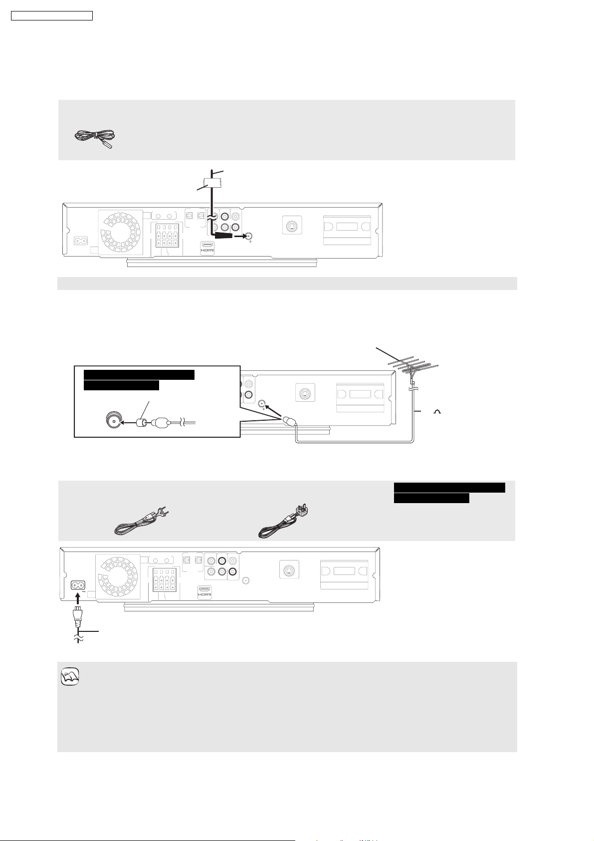
7.6.3. Radio Antenna and AC Power Supply Cord Connections
Radio antenna connections
FM Indoor antenna
FM indoor antenna (included)
Affix this end of the antenna where reception is best.
Keep loose antenna cables away from other wires and cables.
This unit
Adhesive tape
VIDEO OUT
FM ANT
75
Using an FM outdoor antenna (optional)
Use outdoor antenna if radio reception is poor.
Disconnect the antenna when the unit is not in use.
Do not use the outdoor antenna during an electrical storm.
FM outdoor antenna
[Using a TV antenna (not included)]
The antenna should be installed by a competent technician.
For the United Kingdom and
Republic of Ireland
Use the antenna plug adaptor (in luded).
c
VIDEO OUT
AC mains lead connection
AC mains lead
For Continental Europe For the United Kingdom and Republic of Ireland
FM ANT
75
75 coaxial cable
(not included)
This unit
For the United Kingdom and
Republic of Ireland
BE SURE TO READ THE
CAUTION FOR THE AC MAINS
LEAD ON PAGE 2 BEFORE
CONNECTION.
This unit
AC IN
AC mains lead
(included)
To a household mains socket
Power consumption
This unit consumes a small amount of power when it is turned off (approx. 0.4 W). To save power when it is not to be
used for a long time, unplug it from the household mains socket. You will need to reset some memory items after
NOTE
plugging in this unit.
The included AC mains lead is for use with this unit only. Do not use it with other equipment. Also, do not use cords for
other equipment with this unit.
When the AC mains lead is connected for the first time, PLEASE WAIT is displayed on this unit s display for about 30
seconds and the unit is turned off automatically.
22
SA-BT100EB / SA-BT100EG
7.7. Disc and SD Cards Information
7.7.1. Packaged Discs
DivX information is only for the Continental Europe model.
NOTE
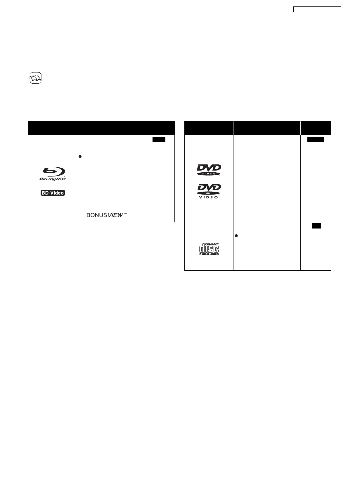
Packaged discs
This chart shows the different type of retail/commercial discs you can use, and also includes the industry-standard logos that
should appear on the discs and/or packaging.
Type of media/
Logo
High Definition (HD) movie
and music discs
Features Indicated
as
BD-V
Type of media/
Logo
Features Indicated
High quality movie and
music discs
as
DVD-V
BD-Video
Discs supporting
BONUSVIEWTM
(BD-ROM version 2
Profile 1 version 1.1/
Final Standard Profile)
that allows Virtual
packages or
Picture-in-Picture
functions to be used.
DVD-Video
CD
Compact Discs (CD s) that
contain audio and music
Operation and sound
quality of CDs that do not
conform to CD-DA
specifications (copy
control CDs, etc.) cannot
be guaranteed.
CD
23
SA-BT100EB / SA-BT100EG
7.7.2. Recorded Discs
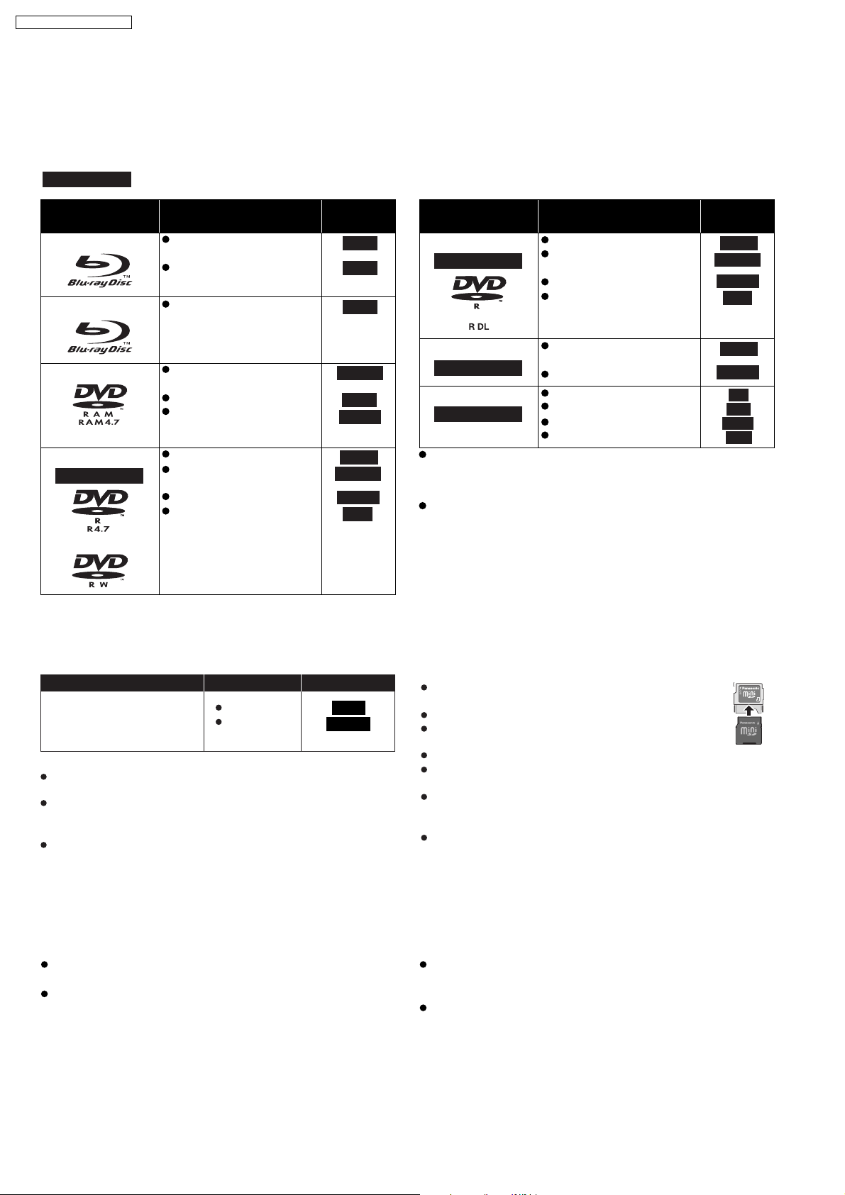
Recorded discs
This chart shows the different type of discs recorded with DVD recorders, DVD video cameras, personal computers, etc. that you
can use.
Finalized
Type of media/
Logo
BD-RE
BD-R
This mark means you must finalize the disc with the DVD recorder, etc. before playback. For details about
finalizing, refer to the operating instructions for your equipment.
Formats Indicated
Version 3 of the BD-RE
Recording Format
JPEG format
as
BD-V
JPEG
Type of media/
Logo
DVD-R DL
Finalized
Formats Indicated
DVD-Video Format
Version 1.2 of the DVD
Video Recording Format
DVD-VR
AVCHD format
Version 2 of the BD-R
BD-V
DivX format
Recording Format
as
DVD-V
AVCHD
DivX
+VR (+R/+RW Video
Recording) Format
AVCHD format
CD-DA format
MP3 format
JPEG format
DivX format
DVD-V
AVCHD
CD
MP3
JPEG
DivX
DVD-RAM
DVD-R/RW
Finalized
Version 1.1 of the DVD
Video Recording Format
JPEG format
AVCHD format
DVD-Video Format
Version 1.1 of the DVD
Video Recording Format
AVCHD format
DivX format (DVD-RW is
not supported)
DVD-VR
JPEG
AVCHD
DVD-V
DVD-VR
AVCHD
DivX
+R/+RW/+R DL
Finalized
CD-R/RW
Finalized
It may not be possible to play the above discs in some
cases due to the type of discs, the condition of the
recording, the recording method and how the files were
created.
When a disc recorded in the AVCHD format is being played,
the video may be paused for a few seconds at portions
spliced, due to deletion or editing.
7.7.3. SD Cards
This chart shows the different type of cards recorded with Panasonic High Definition Video Camera or personal computers, etc. that you can use.
Type of media Features Indicated as
SD Memory Card *
(from 8 MB to 2 GB)
SDHC Memory Card
(from 4 GB to 16 GB)
* Including miniSD Card and microS Card
When using from 4 GB to 16 GB SD cards, only SD cards that
display the SDHC logo can be used.
This unit is compatible with SD Memory Cards that meet SD Card
Specifications FAT12 and FAT16 formats, as well as SDHC Memory
Cards in FAT32 format.
In these operating instructions, the cards shown in the table
are comprehensively called SD cards.
JPEG format
AVCHD
format
JPEG
AVCHD
A miniSD Card and a microSD Card must be used with the
attached adaptor that comes with the card.
Useable memory is slightly less than the card capacity.
If the SD card is formatted on a PC, you may not be able to
use it on this unit. In this case, format the card on this unit.
We recommend using a Panasonic SD card.
Keep the Memory Card out of reach of children to prevent
swallowing.
When a card recorded in the AVCHD format is being played, the
video may be paused for a few seconds at portions spliced, due to
deletion or edition.
Switch teh write-protect switch to the "LOCK" position to protect the
content from accidental erasure.
ADAPTER
7.7.4. Regarding BD-Video
Regarding BD-Video
Enjoy BONUSVIEW functions
,such as
The various functions differ depending on the dics.
When playing a set of two or more BD-Video discs, the menu
screen may continue to display even if the disc has been ejected.
picture-in-picture.
Dolby TrueHD, Dolby Digital Plus, DTS-HD Master Audio and
DTS-HD High Resolution Audio are output as Dolby Digital
when BD-Video Secondary Audio is set to On .
Depending on the intentions of the software producer,
certain discs may not operate according to the details in this
manual. Please refer to the jacket of the disc.
24
7.7.5. Tips for making MP3/JPEG Discs
File format MP3 JPEG
Playable media
CD-R/CD-RW
Extension Files must have the extension .mp3 or .MP3 . Files must have the extension .jpg or .JPG .
Picture
resolution
Compression
32 kbps to 320 kbps
rates
Sampling
44.1 kHz/48 kHz
frequency
Reference ID3 tags: version 1, 2.2, 2.3, 2.4
ID3 is a tag embedded in MP3 track to provide
information about the track.
This unit supports the versions listed above but only
titles and the names of artists can be displayed.
If there is a large amount of still picture data
etc. within a MP3 file, play may not be possible.
File format DivX Subtitles text file of DivX
Playable media
CD-R/RW
File format MicroDVD, SubRip, or TMPlayer
Extension Files must have the extension .DIVX , .d ivx ,
.AVI or .avi .
Picture
between 32k 32 and 720k 576 pixels
resolution
Reference Plays all versions of DivX video (including
DivX
fi
files. Certified to the DivX Home Theater
Profile.
Video
Number of stream: Up to 1
Codec: DIV3, DIV4, DIVX, DV50, DIV6
FPS (Frame Per Second): Up to 30 fps
Audio
Number of stream: Up to 8
Format: MP3, MPEG, AC3
Multi channel: AC3 is possible. MPEG multi
is 2 ch conversion.
GMC (Global Motion Compensation) is not
supported.
English alphabet and Arabic numerals are displayed
correctly. Other characters may not be displayed correctly.
The display order on this unit may differ from how the order is
displayed on a computer.
Depending on how you create the media (writing software),
files and folders may not play in the order you numbered them.
This unit is not compatible with packet-write format.
Depending on the recording conditions, the media may not play.
Operation may take time to complete when there are many
files and/or folders and some files may not display or be
playable.
Structure of MP3, still pictures (JPEG) and DivX folders
You can play MP3, still pictures (JPEG) and DivX with this unit by making folders on
disc as shown.
Folder structure created on a DVD-RAM, BD-RE or an SD card is not displayed.
MP3 files and folders in CD-R/CD-RW
Prefix with 3-digit numbers in the order you want to play them.
Still pictures (JPEG) in CD-R/CD-RW
Files inside a folder are displayed in the order they were updated or taken.
When the highest level folders are DCIM folders, they are displayed first on the tree.
*1
*1
, DVD-R*5, DVD-R DL
*5 *1 *5 *5
6) with standard playback of DivX
fi
media
CD-R/CD-RW*1, DVD-RAM*2, BD-RE*3, SD card
between 34k 34 and 5120k 3840 pixels
(sub sampling is 4:2:2 or 4:2:0)
MOTION JPEG: not supported
Progressive JPEG is not supported.
SD card: JPEG conforming DCF
Thawing Time: approx. 2 sec. (7M pixels)
CD-R/RW , DVD-R , DVD-R DL
Files must have the extension .SRT , .srt , . SUB , .su b ,
.TXT , or .txt
The DivX video file and subtitles text file are inside the same folder,
and the file names are the same except for the file extensions.
If there are more than one subtitles text files inside the same
folder, they are displayed in the following order of priority:
.srt , .sub , .txt .
In the following situations, the subtitles cannot be displayed
as recorded. Furthermore, depending on the methods used
to create the file or the state of the recording, only parts of
the subtitles may be displayed, or the subtitles may not be
displayed at all.
When special text or characters are included in the
subtitles text.
When the file size is larger than 256 KB.
When characters with styling specified are included in the
subtitle data.
Codes that specify the character style within files are
displayed as subtitle characters.
When data with a different format exists within the subtitle
data.
If the file name of the DivX video file is not displayed
correctly on the menu screen (the file name is displayed as
_ ), the subtitles text may not be displayed correctly.
Depending on the disc, the subtitles text cannot be displayed
when search and other such operations are being performed.
*1
ISO9660 level 1 or 2 (except for extended formats), Joliet
This unit is compatible with multi-session.
*2
Discs must conform to UDF 2.0.
*3
Discs must conform to UDF 2.5.
*4
Design rule for Camera File system: unified standard
established by Japan Electronics and Information
Technology Industries Association (JEITA).
*5
Discs must conform to UDF bridge (UDF 1.02/ISO9660).
This unit is not compatible with multi-session. The default
session only is played.
e.g.,
Root
Order of play
*4
P0000001.jpg
P0000002.jpg
001
004 Folder
002 Folder
P0000003.jpg
P0000004.jpg
P0000005.jpg
003 Folder
P0000010.jpg
P0000011.jpg
P0000012.jpg
SA-BT100EB / SA-BT100EG
P0000006.jpg
P0000007.jpg
P0000008.jpg
P0000009.jpg
25

SA-BT100EB / SA-BT100EG
7.7.6. Discs that cannot be played
BD-Video discs recorded at a rate of 50 frame per second
BD-RE with the cartridge
DVD-RAM that cannot be removed from their cartridges
2.6 GB and 5.2 GB DVD-RAM
3.95 GB and 4.7 GB DVD-R for Authoring
Version 1.0 of DVD-RW
+R 8 cm (3z), DVD-ROM, CD-ROM, CDV, SACD, Photo CD,
MV-Disc and PD
DVD-Audio
Video CD and SVCD
WMA discs
DivX discs
PA L d i s cs
HD DVD
Other discs that are not specifically supported
26
SA-BT100EB / SA-BT100EG
8 Operation Instructions
8.1. Taking out the Disc from BD/DVD Drive Unit when Disc cannot be
ejected by OPEN/CLOSE button
8.1.1. Forcible Disc Eject
8.1.1.1. When the power can be turned off.
1. Turn off the power and press [SKIP REV] and [PLAY] keys on the front panel simultaneously for 5 seconds.
8.1.1.2. When the power can not be turned off.
1. Press [POWER] key on the front panel for over10 seconds to turn off thepower forcibly, and press [SKIP REV] and [PLAY] key
on the front panel simultaneously for 5 seconds.
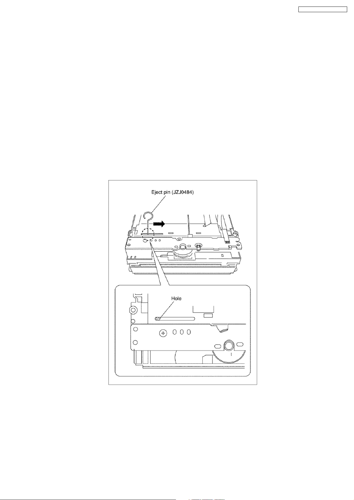
8.1.2. When the Forcible Disc Eject can not be done.
1. Turn off the power and pull out AC cord.
2. Remove the Top Cover and BD/DVD Drive.
3. Insert Eject Pin (JZJ0484) into the hole on the bottom of BD/DVD Drive and slide the Eject Pin in the direction of the arrow to
eject tray slightly.
27

SA-BT100EB / SA-BT100EG
9 Service Mode
9.1. Self-Diagnosis and Special Mode Setting
Self-Diagnosis Function provides information for error to service personnel by Self-Diagnosis Display when any error has occurred.
U**, H** and F** are stored in my memory and held.
•
• You can check latest error code by transmitting [0] [1] of Remote Control in Service Mode.
• •
Automatic Display on FL will be cancelled when the power is turned off or AC input is turned off during self-diagnosis display
is ON.
28
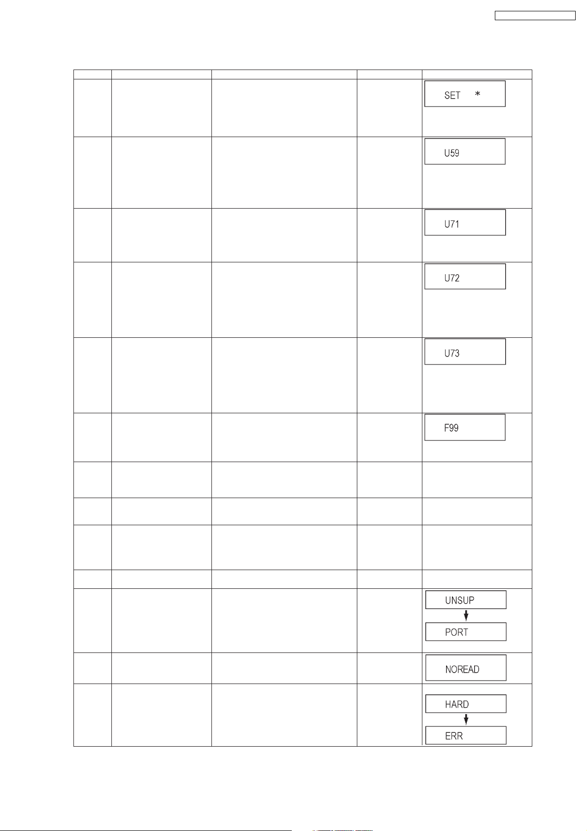
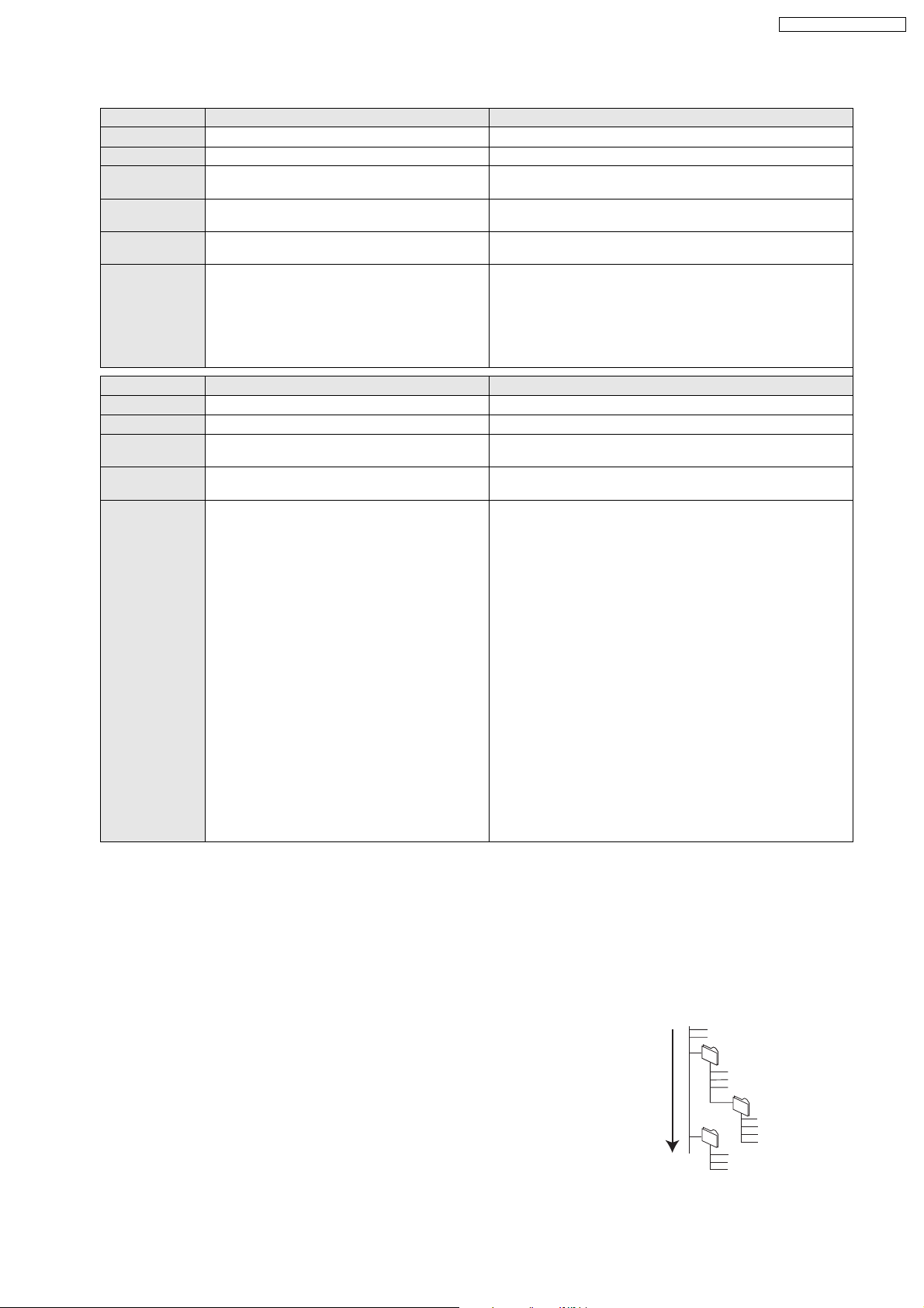
9.1.1. Error Code Table 1
Error Code Diagnosis contents Description Monitor Display Automatic FL display
U30 Remote control code error Display appears when main unit and remote
U59 Abnormal inner temperature
U71 HDMI incompatible error
U72 HDMI connection error
U73 HDMI connection error
F99 Hang-up Displayed when communication error has
H19 Inoperative fan motor When inoperative fan motor is detected after
F00 No error information Initial setting for error code in memory
F34 Initialization error when main
F58 Drive hardware error When drive unit error is detected, the event is
UNSUPPORT
detected
(HDCP incompatible)
(communication error)
(authentication error)
microprocessor is started up
for program recording
Unsupported disc error *An unsupported format disc was played,
controller codes are not matched.
Display appears when the drive temperature
exceeds 70 C.
The power is turned off forcibly.
For 30 minutes after this, all key entries are
disabled. (Fan motor operates at the highest
speed for the first 5 minutes. For the remaining 25 minutes, fan motor is also stopped.)
The event is saved in memory as well.
Display this error when the equipment (compatible with DVI such as TV, amplifier etc.)
connected to the unit by HDMI is incompatible
with HDCP.
*HDCP=High-bandwidth Digital Content Protection
This error is displayed when there are any
communication problems with the unit and the
equipments (TV, amplifier etc.) connected to
the unit by HDMI. (or when there is a problem
with the HDMI cable)
when authentication error occurs while the
equipments (TV, amplifier etc.) are connected
by HDMI. (or when there is a problem with the
HDMI cable)
occurred between Main microprocessor
(MV2-PLUS (IC60009)) and Timer microprocessor (IC7501).
powered on, the power is turned off
automatically.
The event is saved in memory.
(Error code Initialization is possible with error
code initialization and main unit initialization.)
When initialization error is detected after
starting up main microprocessor MV2-PLUS
(IC60009), the power is turned off
automatically.
The event is saved in memory.
saved in memory.
although the drive starts normally.
*The data format is not supported, although
the media type is supported.
*Exceptionally in case of the disc is dirty.
No display
* is remote controller code of the
main unit.
Display for 5 seconds.
No display
U59 is displayed for 30 minutes.
No display
No display
U72 display disappears when
error has been solved by Power
OFF/ON of connecting equipment
or by inserting/removing of HDMI
cable.
No display
U73 display disappears when
error has been solved by Power
OFF/ON of connecting equipment
or by inserting/removing of HDMI
cable.
No display
Displayed is left until the [POWER]
key is pressed.
No display No display
No display No display
No display No display
No display No display
This disc is
incompatible.
SA-BT100EB / SA-BT100EG
NO READ Disc read error *A disc is flawed or dirty.
HARD
ERR
Drive error The drive detected a hard error. DVD drive error. Display for 5 seconds.
*A poor quality failed to start.
*The track information could not be read.
Cannot rea d.
Display for 5 seconds.
Please check the
disc.
29
Diagnosis Contents
SA-BT100EB / SA-BT100EG
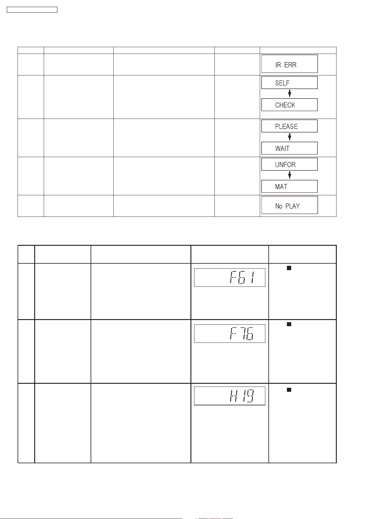
9.1.2. Error Code Table 2
Error Code Diagnosis contents Description Monitor Display Automatic FL display
IR ERR IR communication error [IR ERR] is displayed when communication
SELF
CHECK
PLEASE
WAIT
Restoration operation Since the power cord fell out during a power
Unit is in termination process Unit is in termination process now.
between Timer microprocessor and IR microprocessor fails.
failure or operation, it is under restoration
operation.
*It will OK, if a display disappears automatically. If a display does not disappear, there is
the possibility that defective Digital P.C.B. /
DVD drive.
BYE is displayed and power will be turned off.
No display
No display
No display
UNFORMAT
No PLAY When there is a viewing restric-
Unformatted disc error You have inserted an unformatted DVD-RAM
or DVD-RW that is unformatted or recorded
on other equipment.
Rating password is set. No display
tion on a BD-Video or DVDVideo.
The disc is not
formatted properly.
9.1.3. Power Supply & Digital Amplifier Error Code Table
Error
Code
F61 The abnormalities In normal operation, when DCDET2 goes Press [ STOP] on main
in an output or power to "L" (Low) (Not during POWER OFF unit for next error.
supply circuit of condition), F61 appears on FLDisplay
POWER AMP for 1 second and PCONT goes to
"L" (Low).This is due to speaker output
has DC voltage or fan is not working.
F76F76
Abnormality in the
output voltage of detected "L" (Low) for two consecutive unit for next error.
stabilized power times, F76 is displayed on FL for
supply 1 second and after that PCONT will be
In normal operation when DCDET1 is
turned to "L" (Low). This is due to any of
the DC voltages (+9V, +7V, -7V, +5V,
+5.3V etc.) C22 not available.
Description of error Automatic FL Display Remarks
Press [ STOP] on main
H19
Fan Module
Fan Module is not operating properly
Press [ STOP] on main
unit for next error.
30
 Loading...