

Panasonic s-24mu2u6, s-36mu2u6 installation
INSTALLATION INSTRUCTIONS
Air Conditioner
This air conditioner uses the refrigerant R410A.
Model No.
Indoor Units
Type Indoor Unit Type
S-24MU2U6 S-36MU2U6
U2 4-Way Cassette 36” × 36”
(CZ-36KPU3U)* (CZ-36KPU3U)*
*Panel (optional parts)
Nominal Capacity
24 36
Read through the Installation Instructions before you proceed with the installation.
In particular, you will need to read under the “IMPORTANT!” section at the top of the page.
F616838
IMPORTANT!
Please Read Before Starting
This air conditioning system meets strict safety and
operating standards. As the installer or service person, it is
an important part of your job to install or service the
system so it operates safely and efficiently.
For safe installation and trouble-free operation, you
must:
● Carefully read this instruction booklet before beginning.
● Follow each installation or repair step exactly as shown.
● This air conditioner shall be installed in accordance with
National Wiring Regulations.
● Pay close attention to all warning and caution notices
given in this manual.
This symbol refers to a hazard or
WARNING
CAUTION
If Necessary, Get Help
These instructions are all you need for most installation
sites and maintenance conditions. If you require help for a
special problem, contact our sales/service outlet or your
certified dealer for additional instructions.
In Case of Improper Installation
The manufacturer shall in no way be responsible for
improper installation or maintenance service, including
failure to follow the instructions in this document.
SPECIAL PRECAUTIONS
WARNING
ELECTRICAL SHOCK CAN CAUSE
SEVERE PERSONAL INJURY OR DEATH.
ONLY A QUALIFIED, EXPERIENCED
ELECTRICIAN SHOULD ATTEMPT TO
WIRE THIS SYSTEM.
• Do not supply power to the unit until all wiring and tubing
are completed or reconnected and checked.
• Highly dangerous electrical voltages are used in this system.
Carefully refer to the wiring diagram and these instructions
when wiring. Improper connections and inadequate
grounding can cause accidental injury or death.
• Ground the unit following local electrical codes.
• Connect all wiring tightly. Loose wiring may cause over-
heating at connection points and a possible fire hazard.
• To prevent possible hazards from insulation failure,
the unit must be grounded.
• This equipment is strongly recommended to be installed
with Earth Leakage Circuit Breaker (ELCB) or Residual
Current Device (RCD). Otherwise, it may cause electrical
shock and fire in case of equipment breakdown or
insulation breakdown.
unsafe practice which can result
in severe personal injury or death.
This symbol refers to a hazard or
unsafe practice which can result
in personal injury or product or
property damage.
When Wiring
When Transporting
Be careful when picking up and moving the indoor and
outdoor units. Get a partner to help, and bend your knees
when lifting to reduce strain on your back. Sharp edges or
thin aluminum fins on the air conditioner can cut your
fingers.
When Installing…
Select an installation location which is rigid and strong
enough to support or hold the unit, and select a location for
easy maintenance.
…In a Room
Properly insulate any tubing run inside a room to prevent
“sweating” that can cause dripping and water damage to
walls and floors.
Keep the fire alarm and the air
CAUTION
…In Moist or Uneven Locations
Use a raised concrete pad or concrete blocks to provide a
solid, level foundation for the outdoor unit. This prevents
water damage and abnormal vibration.
…In an Area with High Winds
Securely anchor the outdoor unit down with bolts and a
metal frame. Provide a suitable air baffle.
…In a Snowy Area (for Heat Pump-type Systems)
Install the outdoor unit on a raised platform that is higher
than drifting snow. Provide snow vents.
outlet at least 5 feet (1.5 m) away
from the unit.
When Connecting Refrigerant Tubing
• Pay particular attention to refrigerant leakages.
• Ventilate the room immediately, in the event that is
refrigerant gas leaks during the installation. Be careful not
to allow contact of the refrigerant gas with a flame as this
will cause the generation of toxic gas.
• Keep all tubing runs as short as possible.
• Apply refrigerant lubricant to the matching surfaces of the
flare and union tubes before connecting them, then tighten
the nut with a torque wrench for a leak-free connection.
• Check carefully for leaks before starting the test run.
WARNING
• When performing piping work, do not mix air
except for specified refrigerant (R410A) in
refrigeration cycle. It causes capacity down, and
risk of explosion and injury due to high tension
inside the refrigerant cycle.
• If the refrigerant comes in contact with a flame,
it produces a toxic gas.
• Do not add or replace refrigerant other than
specified type. It may cause product damage,
burst and injury, etc.
2
• Do not leak refrigerant while piping work for an
installation or re-installation, and while repairing
refrigeration parts.
Handle liquid refrigerant carefully as it may cause
frostbite.
When Servicing
• Turn the power OFF at the main power box (mains)
before opening the unit to check or repair electrical
parts and wiring.
• Keep your fingers and clothing away from any moving
parts.
• Clean up the site after you finish, remembering to
check that no metal scraps or bits of wiring have been
left inside the unit .
CAUTION
• Do not touch the air inlet or the sharp
aluminum fins of the outdoor unit. You
may get injured.
• Ventilate any enclosed areas when installing or
testing the refrigeration system. Leaked
refrigerant gas, on contact with fire or heat, can
produce dangerously toxic gas.
• Confirm after installation that no refrigerant gas
is leaking. If the gas comes in contact with a
burning stove, gas water heater, electric room
heater or other heat source, it can cause the
generation of toxic gas.
WARNING
• This product must not be modified or
disassembled under any circumstances.
Modified or disassembled unit may cause fire,
electric shock or injury.
• Do not clean inside the indoor and outdoor
units by users. Engage authorized dealer or
specialist for cleaning.
• In case of malfunction of this appliance, do
not repair by yourself. Contact to the sales
dealer or service dealer for a repair.
Check of Density Limit
The room in which the air conditioner is to be
installed requires a design that in the event of
refrigerant gas leaking out, its density will not exceed
a set limit.
The refrigerant (R410A), which is used in the air
conditioner, is safe, without the toxicity or combustibility of
ammonia, and is not restricted by laws imposed to protect
the ozone layer. However, since it contains more than air,
it poses the risk of suffocation if its density should rise
excessively. Suffocation from leakage of refrigerant is
almost non-existent. With the recent increase in the
number of high density buildings, however, the installation
of multi air conditioner systems is on the increase
because of the need for effective use of floor space,
individual control, energy conservation by curtailing heat
and carrying power, etc.
Most importantly, the multi air conditioner system is able
to replenish a large amount of refrigerant compared to
conventional individual air conditioners.
Others
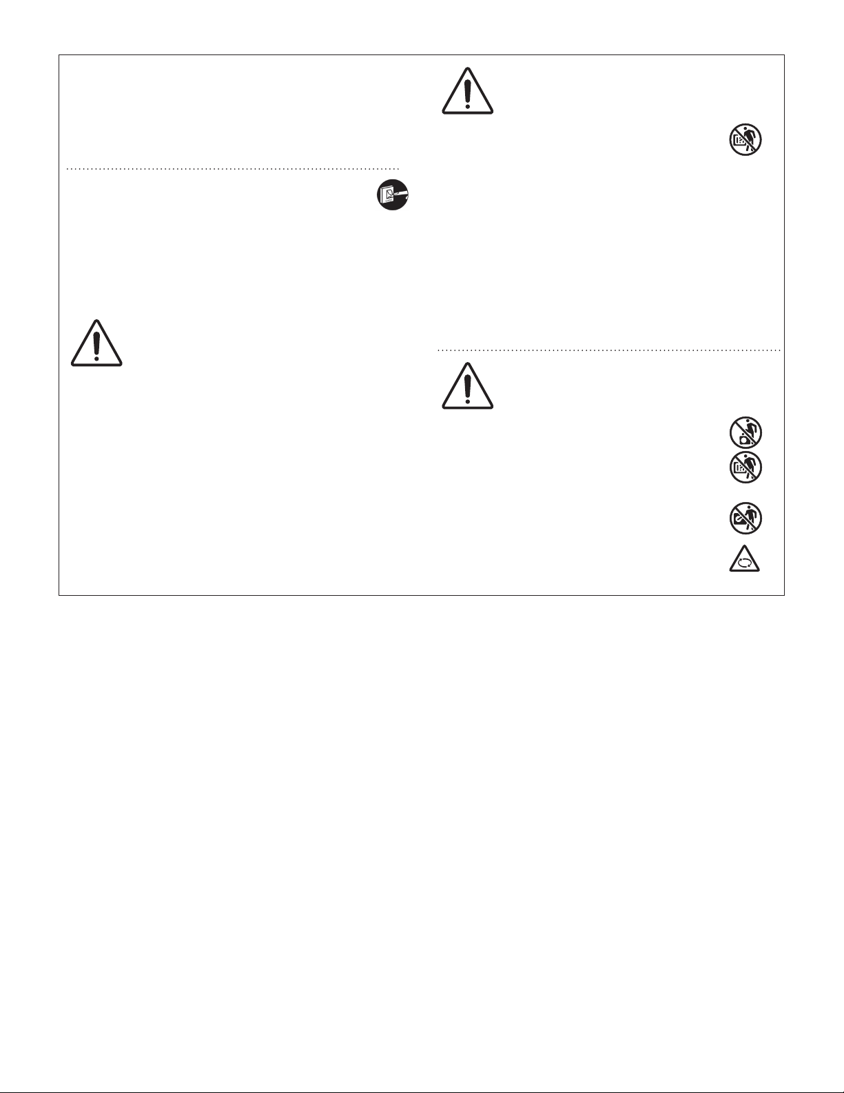
CAUTION
• Do not sit or step on the unit, you may
fall down accidentally.
• Do not touch the air inlet or the sharp
aluminum fins of the outdoor unit.
You may get injured.
• Do not stick any object into the FAN
CASE.
You may be injured and the unit may
be damaged.
If a single unit of the multi air conditioner system is to be
installed in a small room, select a suitable model and
installation procedure so that if the refrigerant
accidentally leaks out, its density does not reach the limit
(and in the event of an emergency, measures can be
made before injury can occur).
ASHRAE and the International Mechanical Code of the
ICC as well as CSA provide guidance and define
safeguards related to the use of refrigerants, all of which
define a Refrigerant Concentration Level (RCL) of
25 pounds (11.3 kg) per 1,000 cubic feet (28.3 m
R410A refrigerant.
For additional guidance and precautions related to
refrigerant safety, please refer to the following documents:
International Mechanical Code 2012 (IMC-2012)
(or more recently revised)
ASHRAE 15
ASHRAE 34
3
) for
3

CONTENTS
Page Page
IMPORTANT . . . . . . . . . . . . . . . . . . . . . . . . . . . . . . . . . . . . . . 2
Please Read Before Starting
Check of Density Limit
1. GENERAL . . . . . . . . . . . . . . . . . . . . . . . . . . . . . . . . . . . . . 5
1-1. Tools Required for Installation (not supplied)
1-2. Accessories Supplied with Unit
1-3. Type of Copper Tube and Insulation Material
1-4. Additional Materials Required for Installation
2. SELECTING THE INSTALLATION SITE . . . . . . . . . . . . . . 6
2-1. Indoor Unit
3. HOW TO INSTALL THE INDOOR UNIT . . . . . . . . . . . . . . 7
4-Way Cassette Type (Type U2) . . . . . . . . . . . . . . . . . . . . . 7
■
3-1. Preparation for Suspending
3-2. Suspending the Indoor Unit
3-3. Placing the Unit Inside the Ceiling
3-4. How to Process Tubing
3-5. Installing the Drain Pipe
7. HOW TO INSTALL THE CEILING PANEL . . . . . . . . . . . . 21
4-Way Cassette Type (CZ-36KPU3U) . . . . . . . . . . . . . . . 21
■
7-1. Preparation for Ceiling Panel Installation
7-2. How to Install the Ceiling Panel
7-3. Others
8. PRECAUTIONS ON TEST RUN . . . . . . . . . . . . . . . . . . . 29
Checkpoint . . . . . . . . . . . . . . . . . . . . . . . . . . . . . . . . . . . . 29
■
9. HOW TO INSTALL WIRELESS REMOTE CONTROLLER
RECEIVER . . . . . . . . . . . . . . . . . . . . . . . . . . . . . . . . . . . 30
N OT E
Refer to the Operating Instructions attached to the optional
Wireless Remote Controller Receiver.
10. APPENDIX . . . . . . . . . . . . . . . . . . . . . . . . . . . . . . . . . . . 30
Care and Cleaning
■
Troubleshooting
■
Tips for Energy Saving
■
4. ELECTRICAL WIRING . . . . . . . . . . . . . . . . . . . . . . . . . . 12
4-1. General Precautions on Wiring
4-2. Important Note for Wiring 4-Way Cassette Type
4-3. Recommended Wire Length and Wire Diameter for
Power Supply System
4-4. Wiring System Diagrams
5. HOW TO PROCESS TUBING . . . . . . . . . . . . . . . . . . . . . 18
5-1. Connecting the Refrigerant Tubing
5-2. Connecting Tubing Between Indoor and Outdoor Units
5-3. Insulating the Refrigerant Tubing
5-4. Taping the Tubes
5-5. Finishing the Installation
6. HOW TO INSTALL THE TIMER REMOTE CONTROLLER
OR HIGH-SPEC WIRED
REMOTE CONTROLLER (OPTIONAL PART) . . . . . . . . 21
N OT E
Refer to the Operating Instructions attached to the optional
Timer Remote Controller or optional High-spec Wired
Remote Controller.
4
1. GENERAL
This booklet briefly outlines where and how to install the
air conditioning system. Please read over the entire set of
instructions for the indoor and outdoor units and make sure all
accessory parts listed are with the system before beginning.
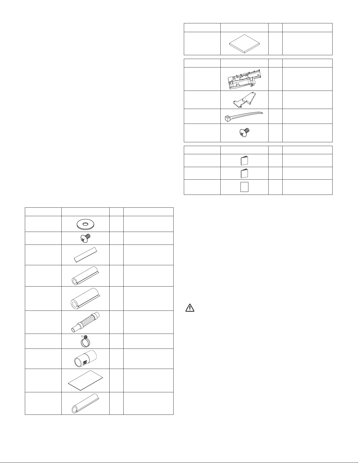
Part Name Figure
Full-scale
installation
diagram
Q’ty
1 Card board
Remarks
1-1. Tools Required for Installation (not supplied)
1. Flathead screwdriver
2. Phillips head screwdriver
3. Knife or wire stripper
4. Tape measure
5. Carpenter’s level
6. Sabre saw or keyhole saw
7. Hacksaw
8. Core bits
9. Hammer
10. Drill
11. Tube cutter
12. Tube flaring tool
13. Torque wrench
14. Adjustable wrench
15. Reamer (for deburring)
1-2. Accessories Supplied with Unit
Table 1-1 (4-Way Cassette)
Part Name Figure
Washer
Screw
Insulating
tape
Flare insulator
Flare insulator
Q’ty
8
4
2
1 For liquid tube
1 For gas tube
Remarks
For suspension
bolts
For full-scale
installation diagram
For gas and liquid
tube flare nuts
Part Name Figure
Wire
mounting
bracket
Wire cover
Clamper
Screw
Part Name
Operating
Instructions
Installation
Instructions
Warranty
card
●
Use 3/8” (M10) for suspension bolts.
●
Field supply for suspension bolts and nuts.
1-3.
Type of Copper Tube and Insulation Material
If you wish to purchase these materials separately from a local
source, you will need:
1. Deoxidized annealed copper tube for refrigerant tubing.
2. Foamed polyethylene insulation for copper tubes as required
to precise length of tubing. Wall thickness of the insulation
should be not less than 5/16” (8 mm).
3. Use insulated copper wire for field wiring. Wire size varies
with the total length of wiring.
Refer to “4. ELECTRICAL WIRING” for details.
CAUTION
Figure
Q’ty
1
1
1
For wire mounting
3
bracket and wire
cover
Q’ty
1
1
1
Remarks
Remarks
Drain hose
Hose band
Drain socket
Packing
Drain
insulator
1
For securing drain
1
hose
1
1 For drain hose joint
1
Check local electrical codes and regulations before
obtaining wire.
limitations.
Also, check any specified instructions or
1-4. Additional Materials Required for Installation
1. Refrigeration (armored) tape
2. Insulated staples or clamps for connecting wire (See your
local codes.)
3. Putty
4. Refrigeration tubing lubricant
5. Clamps or saddles to secure refrigerant tubing
6. Scale for weighing
5
2. SELECTING THE INSTALLATION SITE
2-1. Indoor Unit
AVOID:
● areas where leakage of flammable gas may be expected.
● places where large amounts of oil mist exist.
● direct sunlight.
● locations near heat sources which may affect the performance of the unit.
● locations where external air may enter the room directly.
This may cause “condensation” on the air discharge ports, causing them to spray or drip water.
● locations where the remote controller will be splashed with water or affected by dampness or humidity.
● installing the remote controller behind curtains or furniture.
● locations where high-frequency emissions are generated.
DO:
● select an appropriate position from which every corner of the room can be uniformly cooled.
● select a location where the ceiling is strong enough to support the weight of the unit.
● select a location where tubing and drain pipe have the shortest run to the outdoor unit.
● allow room for operation and maintenance as well as unrestricted air flow around the unit.
● install the unit within the maximum elevation difference above or below the outdoor unit and within a total tubing length (L) from
the outdoor unit as detailed in the installation manual packed with the outdoor unit.
● allow room for mounting the remote controller about 3.3 ft. (1 m) off the floor, in an area that is not in direct sunlight or in the flow
of cool air from the indoor unit.
● if the indoor unit is installed on the ceiling where the temperature or humidity inside is high (over 86°F(30°C)/RH: 70%), add
insulating material to the surface of the unit to avoid dew condensation.
● keep the fire alarm and the air outlet at least 5 ft. (1.5 m) away from the unit.
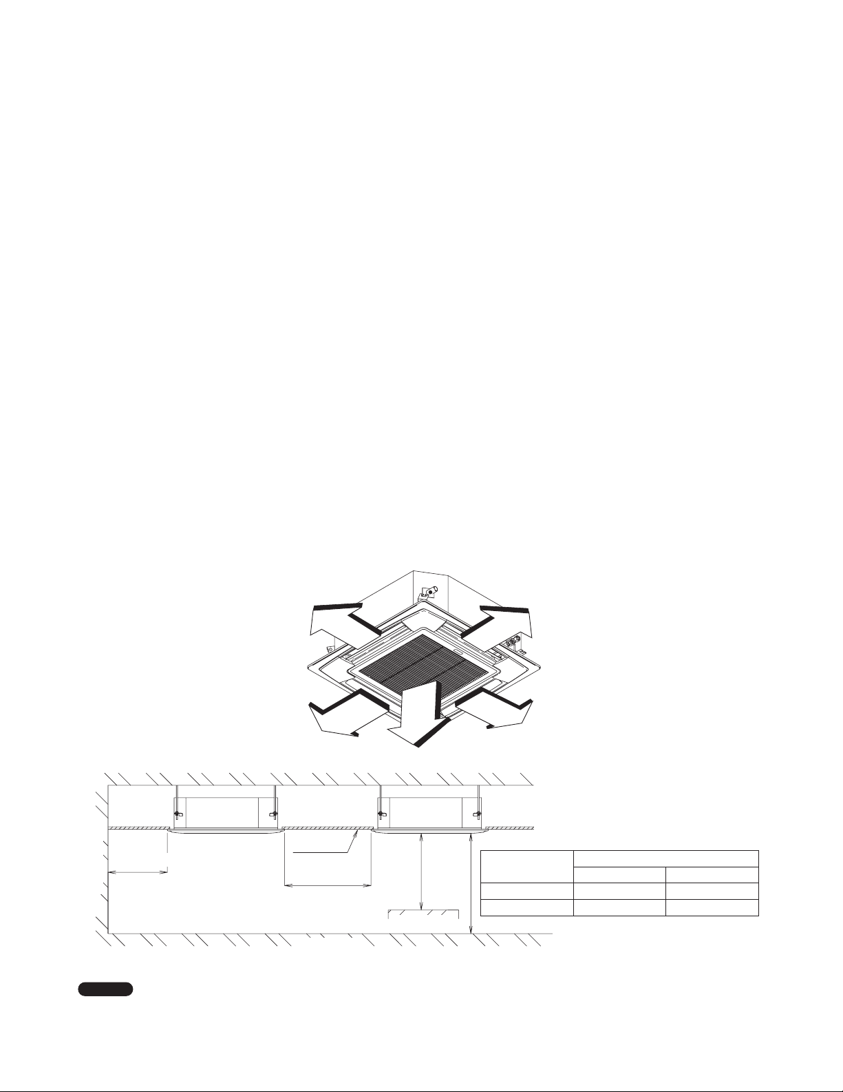
3.3ft.(1 m)
3.3ft.(1 m)
3.3ft.
(1 m)
Model
Floor-to-ceiling height
Minimum Maximum
S-24MU2U6 5.9ft. (1.8m) 11.8ft. (3.6m)
min. 3.3 ft. (1 m)
Wall
indoor unit
Ceiling
min. 10 ft.
3.3ft.(1 m)
(3 m)
3.3ft.
(1 m)
indoor unit
(1 m)
min. 3.3 ft.
S-36MU2U6 5.9ft. (1.8m) 14.8ft. (4.5m)
Obstacles
N OT E
If the floor-to-ceiling height exceeds 9.8ft. (3m), the wind speed distribution becomes poor.
When changing the settings, refer to “7-3. Others” under the section “7. HOW TO INSTALL THE CEILING PANEL”.
6
Fig. 2-1
3. HOW TO INSTALL THE INDOOR UNIT
4-Way Cassette Type (Type U2)
■
3-1. Preparation for Suspending
This unit uses a drain pump. Use a carpenter’s level to check
that the unit is level.
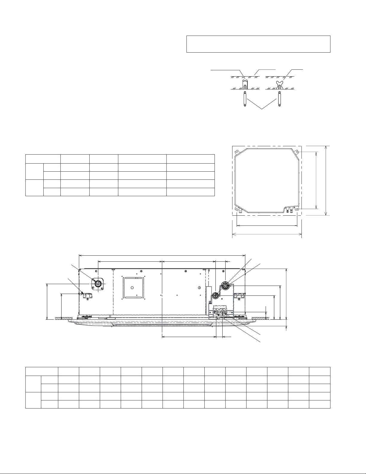
3-2. Suspending the Indoor Unit
(1) Fix the suspension bolts securely in the ceiling using the
method shown in the diagrams (Figs. 3-1 and 3-2), by
attaching them to the ceiling support structure, or by any
other method that ensures that the unit will be securely and
safely suspended.
(2) Follow Fig. 3-2 and Table 3-1 to make the holes in the
ceiling.
Table 3-1
Type A B C D
inch 30-15/16 29-21/64 33-55/64 to 35-53/64 33-55/64 to 35-53/64
24
mm 786 745 860 to 910 860 to 910
inch 30-15/16 29-21/64 33-55/64 to 35-53/64 33-55/64 to 35-53/64
36
mm 786 745 860 to 910 860 to 910
Note: For DC Fan Motor Tap Setting procedure for
4-Way Cassette, see page 24.
Hole-in-anchor
Hole-in-plug
Concrete
Suspension bolt (M10 or 3/8")
(field supply)
Insert
Fig. 3-1
Indoor Unit
View from top
B (suspension bolt pitch)
D (ceiling opening dimension)
A (suspension bolt pitch)
C (ceiling opening dimension)
Drain outlet (other side)
Suspension lug
K
J
Q
P N
O
ML
Refrigerant tubing joint (liquid side)
Refrigerant tubing joint (gas side)
HI
G
F
E
Power supply wiring port
Inter-unit control wiring port
Table 3-2
Type E F G H I J K L M N O P Q
24
36
inch
inch
1-1/2 4-49/64 6-47/64 10-5/64 1-5/16 5-1/8 7-3/32 10-25/32 1-9/32 10-5/8 1-31/32 12-3/4 33-5/64
mm
mm
38 121 171 256 33.5 130 180 274 32.5 270 50 323.8 840
1-1/2 4-49/64 6-47/64 12-9/16 1-5/16 5-1/8 7-3/32 10-25/32 1-9/32 10-5/8 1-31/32 12-3/4 33-5/64
38 121 171 319 33.5 130 180 274 32.5 270 50 323.8 840
Fig. 3-2
Fig. 3-3
7
3-3. Placing the Unit Inside the Ceiling
This unit is equipped with the drain pump. Check a tape
measure or carpenter’s level.
Before installing the ceiling panel, complete the work of
drain pipe and refrigerant pipe installation.
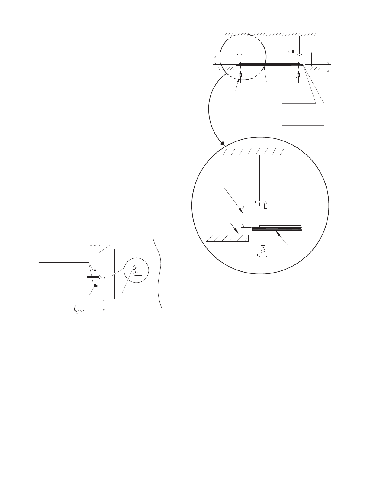
(1) When placing the unit inside the ceiling, determine the
pitch of the suspension bolts using the supplied full-scale
installation diagram. (Fig. 3-4)
Tubing and wiring must be laid inside the ceiling when
suspending the unit. If the ceiling is already constructed, lay
the tubing and wiring into position for connection to the unit
before placing the unit inside the ceiling.
(2) The length of suspension bolts must be appropriate for a
distance between the bottom of the bolt and the bottom of the
unit of more than 45/64” (18 mm) as shown in Fig. 3-4.
(3) Thread the 3 hexagonal nuts and 2 washers (field supply)
onto each of the 4 suspension bolts as shown in Fig. 3-5.
Use 1 nut and 1 washer for the upper side, and 2 nuts and 1
washer for the lower side, so that the unit will not fall off the
suspension lugs.
(4) Adjust so that the distance between the unit and the ceiling
bottom is 15/32” (12 mm) ~ 43/64” (17 mm). Tighten the nuts
on the upper side and lower side of the suspension lug.
(5) Remove the protective polyethylene used to protect the fan
parts during transport.
(6) Check with a tape measure or carpenter’s level.
45/64”
(18 mm)
Over
Screw for
attaching paper
(4 points)
45/64”
Over
(18 mm)
Ceiling
Air
conditioner
Full-scale
installation diagram
Open the ceiling
as large as this
paper outline
Air
conditioner
Ceiling
15/32” (12 mm) ~
43/64” (17 mm)
Suspension bolt
Nuts and washers
(use for upper and lower)
Double nut
15/32” (12 mm) ~ 43/64” (17 mm)
Suspension lug
Notch
3-4. How to Process Tubing
Refer to the section “5. HOW TO PROCESS TUBING”.
Full-scale
installation
diagram
Full-scale installation diagram
Fig. 3-4
Fig. 3-5
8

3-5. Installing the Drain Pipe
3-5-1. Before Performing the Installation Drain Piping
(1) Limitations of Raising the Drain Pipe Connection
CAUTION
●
The drain pipe can be raised to a maximum height of
2.79 ft. (850 mm) from the bottom surface of the ceiling.
Do not attempt to raise it higher than 2.79 ft. (850 mm).
Doing so will result in water leakage. (Fig. 3-6)
(2) Limitations of Drain Pipe Connection
CAUTION
●
Do not install the drain pipe with an upward gradient from the
drain port connection. This will cause the drain water to flow
backward and leak when the unit is not operating. (Fig. 3-7)
●
Do not install an air bleeder as this may cause water to spray
from the drain pipe outlet. (Fig. 3-7)
●
Do not provide U-trap or bell-shaped trap in the middle of the
drain pipe. Doing so will cause abnormal sound.
(Fig. 3-7)
●
Make sure the drain pipe has a downward gradient (1/100 or
more; downward from drain port connection).
(Fig. 3-8)
(3) Limitations of Drain Hose Connection
CAUTION
1 ft. (300 mm) or less
(as short as possible)
B
Indoor unit
Ceiling surface
* Length of supplied drain pipe = 9-27/32” (250 mm)
Air bleeder prohibited
Trap prohibited
Separation of support bracket = 4.92 ft. (1.5 m) ~ 6.56 ft. (2 m)
Indoor unit
Downward gradient = 1/100 or more
A
A : 2.79 ft. (850 mm) or lower
B : 2.2 ft. (670 mm) or lower
Upward gradient
prohibited
Indoor unit
Fig. 3-6
Fig. 3-7
Fig. 3-8
●
Do not bend the supplied drain hose 90° or more.
Bend it less than 45°. (Fig. 3-9)
●
Do not make a trap in the middle of the supplied drain hose.
Doing so will cause abnormal sound. (Fig. 3-10)
Bend angle 90° prohibited
Bend angle less than 45°
Fig. 3-9
Trap prohibited
Fig. 3-10
9
3-5-2. Installing the Drain Hose
CAUTION
●
Do not apply force to the drain port when connecting the
drain hose. Install and fix it near the indoor unit as close as
possible.
●
Do not use adhesive when connecting the drain port pipe
and the drain hose.
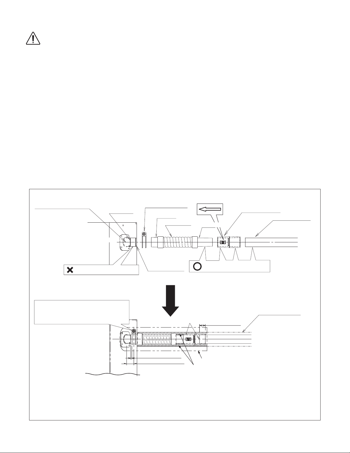
(1) How to Install the Drain Hose
1) First insert the supplied hose band into the drain port pipe.
Then make sure the head of the screw is facing toward a
technical engineer when placing the screw of the hose band
at an upward angle.
2) Insert the soft PVC socket of the supplied drain hose to the
drain port pipe. Do not use adhesive when connecting the
drain hose to the drain port pipe.
Insert it until the tip of the drain hose contacts the circular
projection rib of the drain port pipe.
3) Move the hose band so that the center position of the hose
band can be placed approx. 1-3/16” (30 mm) away from the
external plate of the indoor unit. (Fig. 3-11)
4) Screw the drain hose tightly facing the screw of the hose
band upward. (Torque: 22 - 30 lbf·inch (2.5
N·m - 3.4 N·m))
(If the screw is tightened beneath the drain hose, the
troubles will be generated.) Pay attention not to make hose
band overlap the circular projection rib and the sealed
circulation projection of the drain port hose.
5) Move the drain socket showing in the direction of the arrow
toward the drain hose and connect with the adhesive
(approx. 0.07 oz (2g)).
6) Then connect the hard PVC pipe (field supply) on the
opposite side of the drain socket.
Apply the adhesive (approx. 0.07 oz (2g)) between the two
parts.
After connection, remove sticky adhesive left over the
surface.
Drain port
(Drainage check section on
drain port, transparent)
Do not use adhesive here.
* Drain port may possibly be damaged if
PVC adhesive is used.
Do not make hose band overlap the circular
projection rib and the sealed circulation
projection of the drain port hose. (Torque: 22 - 30
lbf·inch (2.5 N·m - 3.4 N·m))
Circular
projection rib
Indoor unit
Hose band (supplied)
Soft side
Drain hose
(supplied)
Sealed circulation
projection rib
Push until they hit without space.
Approx. 13/64” (5mm)
Approx. 1-3/16” (30mm)
Move the drain socket showing in the direction of the arrow toward
the drain hose and connect with the adhesive
Then connect the hard PVC pipe (field supply) on the opposite
side of the drain socket.
Apply the adhesive
After connection, remove sticky adhesive left over the surface.
Packing (supplied)
Hard side
Adhere with PVC adhesive.
(approx. 0.07 oz (2g))
25/32” (20 mm)
or more
Drain insulator (supplied)
Drain socket (supplied)
Hard PVC pipe (1/2”)
(field supply)
(approx. 0.07 oz (2g))
between the two parts.
Drain insulator
(field supply)
.
* After checking the drainage, wrap the supplied packing and drain hose insulator around the hose.
10
Fig. 3-11
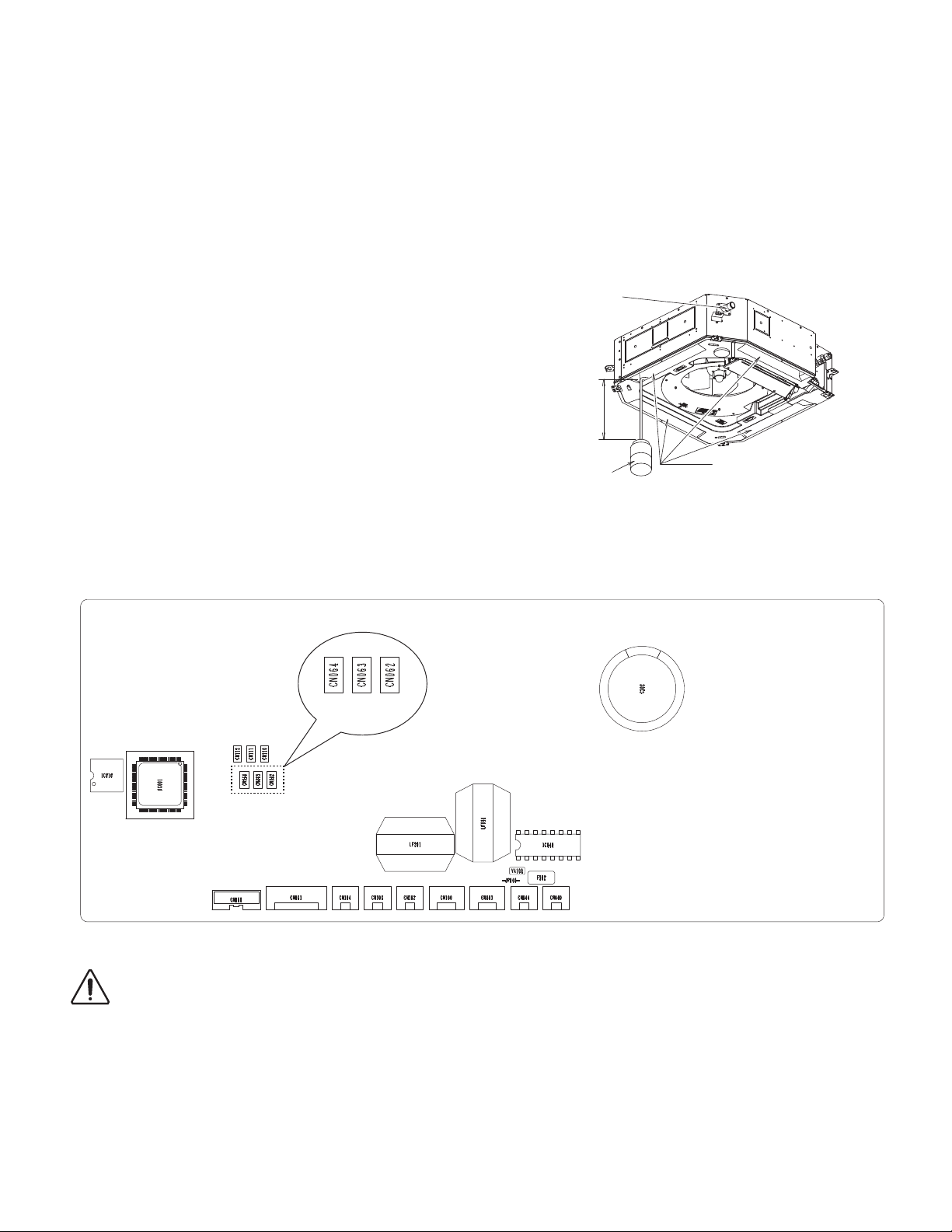
3-5-3. Checking the Drainage
Be careful because the fan will start when you short the pin on the indoor control board.
After wiring (refer to “4. ELECTRICAL WIRING”.) and drain piping are completed, use the following procedure to check that the water
will drain smoothly. For this, prepare a bucket and wiping cloth to catch and wipe up spilled water.
(1) Connect power to the power terminal board (L1, L2 terminals) inside the electrical component box.
(2) Slowly pour about 0.3 gal (1,200 cc) of water into the drain pan to check drainage. (Fig. 3-12)
(3) Short the check pin (CHK) on the indoor control board and operate the drain pump. Check the water flow through the transparent
drain pipe and see if there is any leakage.
(4) When the check of drainage is complete, open the check pin (CHK) and remount the tube cover.
(5) Confirm the “Checkpoint” under the section “8. PRECAUTIONS ON TEST RUN” after installation of indoor and outdoor units,
panels and electrical wiring.
Drainage check
Over 3-15/16” (100 mm)
CHK
Plastic container
for water intake
Drain pan outlet
Water (Approx. 0.3gal (1,200 cc))
Fig. 3-12
CAUTION
Indoor Unit control PC board
Be careful because the fan will start when you short the pin on the indoor control board.
11
 Loading...