

Panasonic S-125PU1R5, S-60PU1R5, S-140PU1R5, S-60PE1R5, S-71PE1R5 Service Manual
...
TECHNICAL DATA
&
SERVICE MANUAL
8546484931000
REFERENCE NO.
SM830210-00
■
R410A Models
Model No.
Indoor Units
Type Indoor Units Type 60 71 100 125 140
U1 4-Way Cassette
S-60PU1R5 S-71PU1R5 S-100PU1R5 S-125PU1R5 S-140PU1R5
E1 Ducted
S-60PE1R5 S-71PE1R5 S-100PE1R5 S-125PE1R5 S-140PE1R5
Outdoor Units
Type
Outdoor Units
Type
60 71 100 125 140
PE1
Single Split
(1-phase)
U-60PE1R5 U-71PE1R5 U-100PE1R5 U-125PE1R5 U-140PE1R5
Single Split
(3-phase)
– – U-100PE1R8 U-125PE1R8 U-140PE1R8
Indoor Unit Outdoor Unit
4-Way Cassette
Ducted
Cover.indd1Cover.indd1 2012/02/2811:59:572012/02/2811:59:57

i
IMPORTANT!
Please Read Before Starting
This air conditioner must be installed by the sales dealer
or installer.
This information is provided for use only by authorized
persons.
For safe installation and trouble-free operation, you must:
●
Carefully read this instruction booklet before beginning.
●
Follow each installation or repair step exactly as shown.
●
This air conditioner shall be installed in accordance with
National Wiring Regulations.
●
Pay close attention to all warning and caution notices
given in this manual.
WARNING
This symbol refers to a hazard or unsafe
practice which can result in severe
personal injury or death.
CAUTION
This symbol refers to a hazard or unsafe
practice which can result in personal injury
or product or property damage.
If Necessary, Get Help
These instructions are all you need for most installation
sites and maintenance conditions. If you require help for a
special problem, contact our sales/service outlet or your
certified dealer for additional instructions.
In Case of Improper Installation
The manufacturer shall in no way be responsible for
improper installation or maintenance service, including
failure to follow the instructions in this document.
SPECIAL PRECAUTIONS
WARNING
When Wiring
ELECTRICAL SHOCK CAN CAUSE
SEVERE PERSONAL INJURY OR DEATH.
ONLY A QUALIFIED, EXPERIENCED
ELECTRICIAN SHOULD ATTEMPT TO
WIRE THIS SYSTEM.
• Do not supply power to the unit until all wiring and tubing
are completed or reconnected and checked.
• Highly dangerous electrical voltages are used in this
system.
Carefully refer to the wiring diagram and these
instructions when wiring. Improper connections and
inadequate grounding can cause accidental injury or
death.
• Connect all wiring tightly. Loose wiring may cause
overheating at connection points and a possible fire
hazard.
• Provide a power outlet to be used exclusively for each
unit.
• Provide a power outlet exclusively for each unit, and
full disconnection means having a contact separation
in all poles must be incorporated in the fixed wiring in
accordance with the wiring rules.
• To prevent possible hazards from insulation failure,
the unit must be grounded.
When Transporting
Be careful when picking up and moving the indoor and
outdoor units. Get a partner to help, and bend your knees
when lifting to reduce strain on your back. Sharp edges
or thin aluminum fins on the air conditioner can cut your
fingers.
When Installing…
Select an installation location which is rigid and strong
enough to support or hold the unit, and select a location
for easy maintenance.
…In a Room
Properly insulate any tubing run inside a room to prevent
“sweating” that can cause dripping and water damage to
walls and floors.
CAUTION
Keep the fire alarm and the air outlet at least
1.5 m away from the unit.
…In Moist or Uneven Locations
Use a raised concrete pad or concrete blocks to provide
a solid, level foundation for the outdoor unit. This prevents
water damage and abnormal vibration.
…In an Area with High Winds
Securely anchor the outdoor unit down with bolts and a
metal frame. Provide a suitable air baffle.
…In a Snowy Area (for Heat Pump-type Systems)
Install the outdoor unit on a raised platform that is higher
than drifting snow. Provide snow vents.
…At least 2.5 m
Indoor unit of this air conditioner shall be installed in a
height of at least 2.5 m.
…In laundry rooms
Do not install in laundry rooms. Indoor unit is not drip proof.
When Connecting Refrigerant Tubing
WARNING
•
When performing piping work do not
mix air except for specified refrigerant
(R410A) in refrigeration cycle. It
causes capacity down, and risk of
explosion and injury due to high
tension inside the refrigerant cycle.
• Refrigerant gas leakage may cause
fire.
• Do not add or replace refrigerant
other than specified type. It may
cause product damage, burst and
injury, etc.
• Ventilate the room well, in the event that is refrigerant
gas leaks during the installation. Be careful not to allow
contact of the refrigerant gas with a flame as this will
cause the generation of poisonous gas.
• Keep all tubing runs as short as possible.
• Use the flare method for connecting tubing.
• Apply refrigerant lubricant to the matching surfaces
of the flare and union tubes before connecting them,
then tighten the nut with a torque wrench for a leak-free
connection.
• Check carefully for leaks before starting the test run.
Cover.inddSec1:iCover.inddSec1:i 2012/02/2811:59:582012/02/2811:59:58

ii
• Do not leak refrigerant while piping work for an
installation or re-installation, and while repairing
refrigeration parts.
Handle liquid refrigerant carefully as it may cause
frostbite.
When Servicing
• Turn the power OFF at the main power box
(mains) before opening the unit to check or repair
electrical parts and wiring.
• Keep your fingers and clothing away from any moving
parts.
• Clean up the site after you finish, remembering to
check that no metal scraps or bits of wiring have been
left inside the unit being serviced.
WARNING
• Do not clean inside the indoor and
outdoor units by users. Engage
authorized dealer or specialist for
cleaning.
• In case of malfunction of this
appliance, do not repair by yourself.
Contact the sales dealer or service
dealer for repair.
CAUTION
• Do not touch the air inlet or the
sharp aluminum fins of the
outdoor unit. You may get injured.
•
Ventilate any enclosed areas when
installing or testing the refrigeration
system. Escaped refrigerant gas, on
contact with fire or heat, can produce
dangerously toxic gas.
•
Confirm after installation that no
refrigerant gas is leaking. If the gas
comes in contact with a burning stove,
gas water heater, electric room heater
or other heat source, it can cause the
generation of poisonous gas.
Others
CAUTION
• Do not touch the air inlet or
the sharp aluminum fins of the
outdoor unit. You may get injured.
• Do not sit or step on the unit,
you may fall down accidentally.
• Do not stick any object into
the FAN CASE.
You may be injured and the
unit may be damaged.
Cover.inddSec1:iiCover.inddSec1:ii 2012/02/2811:59:592012/02/2811:59:59

iii
RoHS
· This product does not contain any hazardous
substances prohibited by the RoHS Directive.
WARNING
· You are requested to use RoHS compliant for
maintenance or repair.
2. The standards for minimum room volume are as follows.
(1) No partition (shaded portion)
(2) When there is an effective opening with the adjacent room
for ventilation of leaking refrigerant gas (opening without
a door, or an opening 0.15% or larger than the respective
floor spaces at the top or bottom of the door).
(3) If an indoor unit is installed in each partitioned room and
the refrigerant tubing is interconnected, the smallest room
of course becomes the object. But when mechanical
ventilation is installed interlocked with a gas leakage
detector in the smallest room where the density limit is
exceeded, the volume of the next smallest room becomes
the object.
3. The minimum indoor floor space compared with the
amount of refrigerant is roughly as follows (for room with
2.7 m high ceiling):
40
35
30
25
20
15
10
5
0
10 20 30
m
2
Check of Density Limit
The room in which the air conditioner is to be installed
requires a design that in the event of refrigerant gas
leaking out, its density will not exceed a set limit.
The refrigerant (R410A), which is used in the air conditioner,
is safe, without the toxicity or combustibility of ammonia, and
is not restricted by laws imposed to protect the ozone layer.
However, since it contains more than air, it poses the risk of
suffocation if its density should rise excessively. Suffocation
from leakage of refrigerant is almost non-existent. With the
recent increase in the number of high density buildings,
however, the installation of multi air conditioner systems is
on the increase because of the need for effective use of floor
space, individual control, and energy conservation by curtailing
heat and carrying power, etc.
Most importantly, the multi air conditioner system is able
to replenish a large amount of refrigerant compared to
conventional individual air conditioners. If a single unit of the
multi air conditioner system is to be installed in a small room,
select a suitable model and installation procedure so that if the
refrigerant accidentally leaks out, its density does not reach the
limit (and in the event of an emergency, measures can be made
before injury can occur).
In a room where the density may exceed the limit, create an
opening with adjacent rooms, or install mechanical ventilation
combined with a gas leak detection device. The density is as
given below.
Total amount of refrigerant (kg)
Min. volume of the indoor unit installed room (m
3
)
< Density limit (kg/m
3
)
The density limit of refrigerant which is used in multi air
conditioners is 0.3 kg/m
3
(ISO 5149).
NOTE
1. If there are 2 or more refrigerating systems in a single
refrigerating device, the amount of refrigerant should be as
charged in each independent device.
For the amount of charge in this example:
The possible amount of leaked refrigerant gas in rooms A,
B and C is 10 kg.
The possible amount of leaked refrigerant gas in rooms D,
E and F is 15 kg.
e.g., charged
amount (10 kg)
Indoor unit
Outdoor unit
e.g., charged
amount (15 kg)
Room A Room B Room C Room D Room E Room F
Outdoor unit
Refrigerant tubing
Indoor unit
Mechanical ventilation device – Gas leak detector
Refrigerant tubing
Outdoor unit
Indoor unit
Very
small
room
Small
room
Medium
room
Large room
Total amount of refrigerant
Min. indoor floor space
Range above the
density limit of 0.3 kg/m
3
(countermeasures needed)
kg
Range below the
density limit of 0.3 kg/m
3
(countermeasures not
needed)
Cover.inddSec1:iiiCover.inddSec1:iii 2012/02/2812:00:012012/02/2812:00:01

1-1
1
1. SPECIFICATIONS
1-1. Unit Specifications................................................................................................... 1-2
4-Way Cassette Type ............................................................................................................................ 1-2
Ducted Type .......................................................................................................................................... 1-7
1-2. Dimensional Data ..................................................................................................... 1-15
(A) Indoor Units ..................................................................................................................................... 1-15
(B) Outdoor Units .................................................................................................................................. 1-18
1-3. Refrigerant Flow Diagram ....................................................................................... 1-20
1-4. Operating Range ...................................................................................................... 1-21
1-5. Capacity Correction Graph According to Temperature Condition ...................... 1-22
1-6. Noise Criterion Curves ............................................................................................ 1-27
1-7. Indoor Fan Performance .......................................................................................... 1-32
1-8. Airflow Distance Chart ............................................................................................ 1-33
1-9. Intaking Fresh Air of 4-Way Cassette Type ............................................................ 1-35
1-10. Electrical Wiring ....................................................................................................... 1-37
1-11. Installation instructions .......................................................................................... 1-40
Sec1.indb1Sec1.indb1 2012/03/0717:29:532012/03/0717:29:53
1-2
1
Single-Type
1-1. Unit Specifi cations
4-Way Cassette Type S-60PU1R5 / U-60PE1R5
INDOOR MODEL
S–60PU1R5
PANEL MODEL
CZ–KPU2
OUTDOOR MODEL
U–60PE1R5
Branch pipe MODEL
–
PERFORMANCE TEST CONDITION
ISO5151 / AS/NZS3823
POWER SUPPLY
ø, Hz
1ø 50 Hz 1ø 50 Hz
V
230 V 240 V 230 V 240 V Min Max
C
O
O
L
I
N
G
CAPACITY
kW
6.0 6.0 2.5 7.1
BTU/h
20500 20500 8500 24200
CURRENT A
0.31 0.30 6.90 6.70 – –
INPUT POWER
W
35 35 1.445 k 1.445 k – –
TOTAL W
– 1.480 k 1.480 k 450 2.000 k
ANNUAL CONSUMPTION TOTAL W *
4
– 740 – – –
EER/AEER /STR RAT TOTAL (W/W)
–––
4.05/3.94/3.0
4.05 5.56 3.55
POWER FACTOR %
– – 91 90 – –
NOISE INDOOR
(H/M/L)
dB–A
36/31/28
Power Level dB
53/48/45
NOISE OUTDOOR
(H/L)
dB–A
48/–
Power Level dB
65/–
H
E
A
T
I
N
G
CAPACITY
kW
7.0 7.0 2.0 8.0
BTU/h
23900 23900 6800 27300
CURRENT A
0.30 0.29 8.20 7.95 – –
INPUT POWER
W
35 35 1.775 k 1.775 k – –
TOTAL W
– 1.810 k 1.810 k 400 2.480 k
COP/ACOP /STR RAT TOTAL (W/W)
–––
3.87/3.78/3.0
3.87 5.00 3.23
POWER FACTOR %
– – 94 93 – –
NOISE INDOOR
(H/M/L)
dB–A
36/31/28 – / /
Power Level dB
53/48/45 –
NOISE OUTDOOR
(H/L)
dB–A
– 50/– / /
Power Level dB
– 67/–
EXTRA LOW TEMP
TOTAL CAPACITY(kW)/INPUT POWER(W)/COP
–
MAX CURRENT(A)/MAX INPUT POWER(W)
0.31/35 0.30/35
18.0/3.930 k 18.0/4.060 k
/
STARTING CURRENT(A)/COMP OUTPUT(W)
––
8.20/1.7 K
7.95/1.7 K
/
NETWORK IMPEDANCE(ΩMAX.)
––
FM OUTPUT (W)
60 90 /
MOISTURE REMOVAL VOLUME L/h(Pt/h)
3.4 (7.1) –
Extarnal static pressure
Pa (mmAq)
–
I/D AIR
FLOW
COOL m
3
/min (ft3/min)
21 (742)
HEAT m3/min (ft3/min)
21 (742)
O/D AIR
FLOW
COOL m
3
/min (ft3/min)
60 (2119)
HEAT m3/min (ft3/min)
60 (2119)
REFRIGERANT TYPE, AMOUNT g(oz)
R410A 2.00 k (70.5) /
P
R
O
D
I
M
HEIGHT: H mm (inch)
256 (10–3/32) 996 (39-7/32) /
WIDTH: W mm (inch)
840 (33–3/32) 940 (37–1/32) /
DEPTH: D mm (inch)
840 (33–3/32) 340 (13–13/32) /
P
A
C
D
I
M
HEIGHT: H mm
298 1136 /
WIDTH: W mm
929 1055 /
DEPTH: D mm
929 485 /
MASS
(NET) kg(lb)
24(53) 68(150) /
(GROSS) kg(lb)
29(64) 76(168) /
LAYERS LIMIT (actually)
11(12) 2(3)
Operation
Condition
Cool (DBT) 18˚C – 32˚C -15˚C – 46˚C
Heat (DBT) 16˚C – 30˚C -20˚C – 24˚C
P
I
P
I
N
G
PIPE DIAMETER mm (inch)
(Liquid)ø9.52(3/8) (Gas)ø15.88(5/8) (Liquid)ø9.52(3/8) (Gas)ø15.88(5/8)
CONNECT METHOD, STD LENGTH m (ft)
fl ared type, 5.0(16.4) fl ared type, 5.0(16.4)
PIPE LENGTH RANGE m (ft)
5 – 50 (16.4 – 164.0) – –
I/D&O/D HEIGHT DIRRERENCE m (ft)
15 (OD located lower)/30 (OD located higher) (49.2/98.4)
ADD GAS AMOUNT g/m (oz/ft)
50 (537.6)
PIPE LENGTH FOR ADDITIONAL GAS m (ft)
30 (98.4)
*1:In case it is necessary to indicate the air fl ow volume in (l/s), the value in (m3/min.) shall be multiplied by 16.7 and rounded down the decimal point.
*2
:
If the EUROVENT Certifi ed models can be operated under the “extra-low” temperature condition, -7°C dry bulb and -8°C wet-bulb temperatures with rated voltage
230 V shall be used.
*3:Network Impedance shall be applicable for EUROPE and CHINA models.
*4:The annual consumption is calculated by multiplying the input power at 230 V (400 V) by an average of 500 hours per year in cooling mode.
*5:EER and COP classification is at 230 V (400 V) only in accordance with EU directive 2002/31/EC.
Sec1.indb2Sec1.indb2 2012/03/0717:29:542012/03/0717:29:54

1-3
1
Single-Type
1-1. Unit Specifi cations
4-Way Cassette Type S-71PU1R5 / U-71PE1R5
INDOOR MODEL
S–71PU1R5
PANEL MODEL
CZ–KPU2
OUTDOOR MODEL
U–71PE1R5
Branch pipe MODEL
–
PERFORMANCE TEST CONDITION
ISO5151 / AS/NZS3823
POWER SUPPLY
ø, Hz
1ø 50 Hz 1ø 50 Hz
V
230 V 240 V 230 V 240 V Min Max
C
O
O
L
I
N
G
CAPACITY
kW
7.1 7.1 2.5 8.0
BTU/h
24200 24200 8500 27300
CURRENT A
0.33 0.32 8.10 7.90 – –
INPUT POWER
W
40 40 1.760 k 1.760 k – –
TOTAL W
– 1.800 k 1.800 k 450 2.650 k
ANNUAL CONSUMPTION TOTAL W *
4
– 900 – – –
EER/AEER /STR RAT TOTAL (W/W)
–––
3.94/3.85/2.5
3.94 5.56 3.02
POWER FACTOR %
– – – 94 93
NOISE INDOOR
(H/M/L)
dB–A
37/31/28
Power Level dB
54/48/45
NOISE OUTDOOR
(H/L)
dB–A
48/–
Power Level dB
65/–
H
E
A
T
I
N
G
CAPACITY
kW
8.0 8.0 2.0 9.0
BTU/h
27300 27300 6800 30700
CURRENT A
0.32 0.31 9.00 8.70 – –
INPUT POWER
W
40 40 1.960 k 1.960 k – –
TOTAL W
– 2.000 k 2.000 k 400 2.900 k
COP/ACOP /STR RAT TOTAL (W/W)
–––
4.00/3.91/3.0
4.00 5.00 3.10
POWER FACTOR %
– – 95 94 – –
NOISE INDOOR
(H/M/L)
dB–A
37/31/28 – / /
Power Level dB
54/48/45 –
NOISE OUTDOOR
(H/L)
dB–A
– 50/– / /
Power Level dB
– 67/–
EXTRA LOW TEMP
TOTAL CAPACITY(kW)/INPUT POWER(W)/COP
–
MAX CURRENT(A)/MAX INPUT POWER(W)
– 0.33/40 0.32/40
18.0/3.930 k 18.0/4.060 k
/
STARTING CURRENT(A)/COMP OUTPUT(W)
–––
9.00/2.0 K
8.70/2.0 K
/
NETWORK IMPEDANCE(ΩMAX.)
––
FM OUTPUT (W)
60 90 /
MOISTURE REMOVAL VOLUME L/h(Pt/h)
4.2 (8.8) –
Extarnal static pressure
Pa (mmAq)
–
I/D AIR
FLOW
COOL m
3
/min (ft3/min)
22 (777)
HEAT m3/min (ft3/min)
22 (777)
O/D AIR FLOW
COOL m
3
/min (ft3/min)
60 (2119)
HEAT m3/min (ft3/min)
60 (2119)
REFRIGERANT TYPE, AMOUNT g(oz)
R410A 2.35 k (82.9) /
P
R
O
D
I
M
HEIGHT: H mm (inch)
256 (10–3/32) 996 (39-7/32) /
WIDTH: W mm (inch)
840 (33–3/32) 940 (37–1/32) /
DEPTH: D mm (inch)
840 (33–3/32) 340 (13–13/32) /
P
A
C
D
I
M
HEIGHT: H mm
298 1136 /
WIDTH: W mm
929 1055 /
DEPTH: D mm
929 485 /
MASS
(NET) kg(lb)
24(53) 69(153) /
(GROSS) kg(lb)
29(64) 77(170) /
LAYERS LIMIT (actually)
11(12) 2(3)
Operation
Condition
Cool (DBT)
18˚C – 32˚C -15˚C – 46˚C
Heat (DBT)
16˚C – 30˚C -20˚C – 24˚C
P
I
P
I
N
G
PIPE DIAMETER mm (inch)
(Liquid)ø9.52(3/8) (Gas)ø15.88(5/8) (Liquid)ø9.52(3/8) (Gas)ø15.88(5/8)
CONNECT METHOD, STD LENGTH m (ft)
fl ared type, 5.0(16.4) fl ared type, 5.0(16.4)
PIPE LENGTH RANGE m (ft)
5 – 50 (16.4 – 164.0) – –
I/D&O/D HEIGHT DIRRERENCE m (ft)
15 (OD located lower)/30 (OD located higher) (49.2/98.4)
ADD GAS AMOUNT g/m (oz/ft)
50 (537.6)
PIPE LENGTH FOR ADDITIONAL GAS m (ft)
30 (98.4)
*1:In case it is necessary to indicate the air fl ow volume in (l/s), the value in (m3/min.) shall be multiplied by 16.7 and rounded down the decimal point.
*2
:
If the EUROVENT Certifi ed models can be operated under the “extra-low” temperature condition, -7°C dry bulb and -8°C wet-bulb temperatures with rated voltage
230 V shall be used.
*3:Network Impedance shall be applicable for EUROPE and CHINA models.
*4:The annual consumption is calculated by multiplying the input power at 230 V (400 V) by an average of 500 hours per year in cooling mode.
*5:EER and COP classification is at 230 V (400 V) only in accordance with EU directive 2002/31/EC.
Sec1.indb3Sec1.indb3 2012/03/0717:29:542012/03/0717:29:54
1-4
1
Single-Type
1-1. Unit Specifi cations
4-Way Cassette Type S-100PU1R5 / U-100PE1R5
INDOOR MODEL S–100PU1R5
PANEL MODEL CZ–KPU2
OUTDOOR MODEL U–100PE1R5
Branch pipe MODEL –
PERFORMANCE TEST CONDITION ISO5151 / AS/NZS3823
POWER SUPPLY
ø, Hz 1ø 50 Hz 1ø 50 Hz
V 230 V 240 V 230 V 240 V Min Max
C
O
O
L
I
N
G
CAPACITY
kW 10.0 10.0 3.3 12.5
BTU/h 34100 34100 11300 42700
CURRENT A 0.71 0.71 10.3 9.90 – –
INPUT POWER
W 95 95 2.285 k 2.285 k – –
TOTAL W – 2.380 k 2.380 k 840 3.700 k
ANNUAL CONSUMPTION TOTAL W *
4
–1190–––
EER/AEER /STR RAT TOTAL (W/W) – –
4.20/4.13/3.0
4.20 3.93 3.38
POWER FACTOR % – – 96 96 – –
NOISE INDOOR
(H/M/L)
dB–A 44/38/32
Power Level dB 62/55/49
NOISE OUTDOOR
(H/L)
dB–A 52/–
Power Level dB 69/–
H
E
A
T
I
N
G
CAPACITY
kW 11.2 11.2 4.1 14.0
BTU/h 38200 38200 14000 47800
CURRENT A 0.65 0.64 11.4 11.0 – –
INPUT POWER
W 85 85 2.515 k 2.515 k – –
TOTAL W – 2.600 k 2.600 k 900 4.400 k
COP/ACOP /STR RAT TOTAL (W/W) – –
4.31/4.24/4.0
4.31 4.56 3.18
POWER FACTOR % – – 96 95 – –
NOISE INDOOR
(H/M/L)
dB–A 44/38/32 – / /
Power Level dB 62/55/49 –
NOISE OUTDOOR
(H/L)
dB–A – 52/– / /
Power Level dB – 69/–
EXTRA LOW TEMP
TOTAL CAPACITY(kW)/INPUT POWER(W)/COP
–
MAX CURRENT(A)/MAX INPUT POWER(W) 0.71/95 0.71/95
25.0/5.550 k 25.0/5.750 k
/
STARTING CURRENT(A)/COMP OUTPUT(W) – –
10.8/3.0 K
10.4/3.0 K
/
NETWORK IMPEDANCE(ΩMAX.) – –
FM OUTPUT (W) 90 90 × 2 /
MOISTURE REMOVAL VOLUME L/h(Pt/h) 6.0 (12.6) –
Extarnal static pressure
Pa (mmAq)
–
I/D AIR
FLOW
COOL m
3
/min (ft3/min) 33 (1165)
HEAT m
3
/min (ft3/min) 33 (1165)
O/D AIR
FLOW
COOL m
3
/min (ft3/min) 110 (3885)
HEAT m3/min (ft3/min) 95 (3355)
REFRIGERANT TYPE, AMOUNT g(oz) R410A 3.40 k (119.9) /
P
R
O
D
I
M
HEIGHT: H mm (inch) 319 (12–9/16) 1416 (55–3/4) /
WIDTH: W mm (inch) 840 (33–3/32) 940 (37–1/32) /
DEPTH: D mm (inch) 840 (33–3/32) 340 (13–13/32) /
P
A
C
D
I
M
HEIGHT: H mm 361 1556 /
WIDTH: W mm 929 1055 /
DEPTH: D mm 929 485 /
MASS
(NET) kg(lb) 27(60) 98(216) /
(GROSS) kg(lb) 33(73) 108(238) /
LAYERS LIMIT (actually) 11(12) 1(2)
Operation
Condition
Cool (DBT) 18˚C – 32˚C -15˚C – 46˚C
Heat (DBT) 16˚C – 30˚C -20˚C – 24˚C
P
I
P
I
N
G
PIPE DIAMETER mm (inch)
(Liquid) ø9.52(3/8) (Gas) ø15.88(5/8) (Liquid) ø9.52(3/8) (Gas) ø15.88(5/8)
CONNECT METHOD, STD LENGTH m (ft) fl ared type, 5.0(16.4) fl ared type, 5.0(16.4)
PIPE LENGTH RANGE m (ft) 5 – 75 (16.4 – 246.1) – –
I/D&O/D HEIGHT DIRRERENCE m (ft) 15 (OD located lower)/30 (OD located higher) (49.2/98.4)
ADD GAS AMOUNT g/m (oz/ft) 50 (537.6)
PIPE LENGTH FOR ADDITIONAL GAS m (ft) 30 (98.4)
*1:In case it is necessary to indicate the air fl ow volume in (l/s), the value in (m3/min.) shall be multiplied by 16.7 and rounded down the decimal point.
*2
:
If the EUROVENT Certifi ed models can be operated under the “extra-low” temperature condition, -7°C dry bulb and -8°C wet-bulb temperatures with rated voltage
230 V shall be used.
*3:Network Impedance shall be applicable for EUROPE and CHINA models.
*4:The annual consumption is calculated by multiplying the input power at 230 V (400 V) by an average of 500 hours per year in cooling mode.
*5:EER and COP classification is at 230 V (400 V) only in accordance with EU directive 2002/31/EC.
Sec1.indb4Sec1.indb4 2012/03/0717:29:542012/03/0717:29:54

1-5
1
Single-Type
1-1. Unit Specifi cations
4-Way Cassette Type S-125PU1R5 / U-125PE1R5
INDOOR MODEL
S–125PU1R5
PANEL MODEL
CZ–KPU2
OUTDOOR MODEL
U–125PE1R5
Branch pipe MODEL
–
PERFORMANCE TEST CONDITION
ISO5151 / AS/NZS3823
POWER SUPPLY
ø, Hz
1ø 50 Hz 1ø 50 Hz
V
230 V 240 V 230 V 240 V Min Max
C
O
O
L
I
N
G
CAPACITY
kW
12.5 12.5 3.3 14.0
BTU/h
42700 42700 11300 47800
CURRENT A
0.76 0.73 15.3 14.8 – –
INPUT POWER
W
100 100 3.370 k 3.370 k – –
TOTAL W
– 3.470 k 3.470 k 840 4.600 k
ANNUAL CONSUMPTION TOTAL W *
4
– 1735 – – –
EER/AEER /STR RAT TOTAL (W/W)
––
3.60/3.56/2.0
3.60 3.93 3.04
POWER FACTOR %
– – 96 95 – –
NOISE INDOOR
(H/M/L)
dB–A
45/39/33
Power Level dB
63/56/50
NOISE OUTDOOR
(H/L)
dB–A
53/–
Power Level dB
70/–
H
E
A
T
I
N
G
CAPACITY
kW
14.0 14.0 4.1 16.0
BTU/h
47800 47800 14000 54600
CURRENT A
0.73 0.73 15.4 14.9 – –
INPUT POWER
W
100 100 3.400 k 3.400 k – –
TOTAL W
– 3.500 k 3.500 k 900 5.200 k
COP/ACOP /STR RAT TOTAL (W/W)
––
4.00/3.95/3.0
4.00 4.56 3.08
POWER FACTOR %
– – 96 95 – –
NOISE INDOOR
(H/M/L)
dB–A
45/39/33 – / /
Power Level dB
63/56/50 –
NOISE OUTDOOR
(H/L)
dB–A
– 53/– / /
Power Level dB
– 70/–
EXTRA LOW TEMP
TOTAL CAPACITY(kW)/INPUT POWER(W)/COP
–
MAX CURRENT(A)/MAX INPUT POWER(W)
– 0.76/100 0.73/100 –
28.0/6.200 k 28.0/6.400 k
/
STARTING CURRENT(A)/COMP OUTPUT(W)
––––
15.7/3.0 K 15.2/3.0 K
/
NETWORK IMPEDANCE(ΩMAX.)
––
FM OUTPUT (W)
90 90 × 2 /
MOISTURE REMOVAL VOLUME L/h(Pt/h)
7.9 (16.6) –
Extarnal static pressure
Pa (mmAq)
–
I/D AIR
FLOW
COOL m
3
/min (ft3/min)
35 (1236)
HEAT m
3
/min (ft3/min)
35 (1236)
O/D AIR
FLOW
COOL m3/min (ft3/min)
130 (4591)
HEAT m
3
/min (ft3/min)
110 (3885)
REFRIGERANT TYPE, AMOUNT g(oz)
R410A 3.40 k (119.9) /
P
R
O
D
I
M
HEIGHT: H mm (inch)
319 (12–9/16) 1416 (55–3/4) /
WIDTH: W mm (inch)
840 (33–3/32) 940 (37–1/32) /
DEPTH: D mm (inch)
840 (33–3/32) 340 (13–13/32) /
P
A
C
D
I
M
HEIGHT: H mm
361 1556 /
WIDTH: W mm
929 1055 /
DEPTH: D mm
929 485 /
MASS
(NET) kg(lb)
27(60) 98(216) /
(GROSS) kg(lb)
33(73) 108(238) /
LAYERS LIMIT (actually)
11(12) 1(2)
Operation
Condition
Cool (DBT) 18˚C – 32˚C -15˚C – 46˚C
Heat (DBT) 16˚C – 30˚C -20˚C – 24˚C
P
I
P
I
N
G
PIPE DIAMETER mm (inch)
(Liquid)ø9.52(3/8) (Gas)ø15.88(5/8) (Liquid)ø9.52(3/8) (Gas)ø15.88(5/8)
CONNECT METHOD, STD LENGTH m (ft)
fl ared type, 5.0(16.4) fl ared type, 5.0(16.4)
PIPE LENGTH RANGE m (ft)
5 – 75 (16.4 – 246.1) – –
I/D&O/D HEIGHT DIRRERENCE m (ft)
15 (OD located lower)/30 (OD located higher) (49.2/98.4)
ADD GAS AMOUNT g/m (oz/ft)
50 (537.6)
PIPE LENGTH FOR ADDITIONAL GAS m (ft)
30 (98.4)
*1:In case it is necessary to indicate the air fl ow volume in (l/s), the value in (m3/min.) shall be multiplied by 16.7 and rounded down the decimal point.
*2
:
If the EUROVENT Certifi ed models can be operated under the “extra-low” temperature condition, -7°C dry bulb and -8°C wet-bulb temperatures with rated voltage
230 V shall be used.
*3:Network Impedance shall be applicable for EUROPE and CHINA models.
*4:The annual consumption is calculated by multiplying the input power at 230 V (400 V) by an average of 500 hours per year in cooling mode.
*5:EER and COP classification is at 230 V (400 V) only in accordance with EU directive 2002/31/EC.
Sec1.indb5Sec1.indb5 2012/03/0717:29:552012/03/0717:29:55

1-6
1
Single-Type
1-1. Unit Specifi cations
4-Way Cassette Type S-140PU1R5 / U-140PE1R5
INDOOR MODEL
S–140PU1R5
PANEL MODEL
CZ–KPU2
OUTDOOR MODEL
U–140PE1R5
Branch pipe MODEL
–
PERFORMANCE TEST CONDITION
ISO5151 / AS/NZS3823
POWER SUPPLY
ø, Hz
1ø 50 Hz 1ø 50 Hz
V
230 V 240 V 230 V 240 V Min Max
C
O
O
L
I
N
G
CAPACITY
kW
14.0 14.0 3.3 15.5
BTU/h
47800 47800 11300 52900
CURRENT A
0.89 0.87 19.0 18.4 – –
INPUT POWER
W
115 115 4.195 k 4.195 k – –
TOTAL W
– 4.310 k 0.000 k 840 6.000 k
ANNUAL CONSUMPTION TOTAL W *
4
– 2155 – – –
EER/AEER /STR RAT TOTAL (W/W)
––
3.25/3.22/1.5
3.25 3.93 2.58
POWER FACTOR %
– – 96 95 – –
NOISE INDOOR
(H/M/L)
dB–A
46/40/34
Power Level dB
64/57/51
NOISE OUTDOOR
(H/L)
dB–A
54/–
Power Level dB
71/–
H
E
A
T
I
N
G
CAPACITY
kW
16.0 16.0 4.1 18.0
BTU/h
54600 54600 14000 61400
CURRENT A
0.80 0.79 19.2 18.6 – –
INPUT POWER
W
105 105 4.225 k 4.225 k – –
TOTAL W
– 4.330 k 4.330 k 900 5.900 k
COP/ACOP /STR RAT TOTAL (W/W)
––
3.70/3.66/2.5
3.70 4.56 3.05
POWER FACTOR %
– – 96 95 – –
NOISE INDOOR
(H/M/L)
dB–A
46/40/34 – / /
Power Level dB
64/57/51 –
NOISE OUTDOOR
(H/L)
dB–A
– 55/– / /
Power Level dB
– 71/–
EXTRA LOW TEMP
TOTAL CAPACITY(kW)/INPUT POWER(W)/COP
–
MAX CURRENT(A)/MAX INPUT POWER(W)
0.89/115 0.87/115
30.0/6.650 k 30.0/6.850 k
/
STARTING CURRENT(A)/COMP OUTPUT(W)
––
19.5/3.0 K 19.0/3.0 K
/
NETWORK IMPEDANCE(ΩMAX.)
––
FM OUTPUT (W)
90 90 × 2 /
MOISTURE REMOVAL VOLUME L/h(Pt/h)
9.0 (18.9) –
Extarnal static pressure
Pa (mmAq)
–
I/D AIR
FLOW
COOL m
3
/min (ft3/min)
36 (1271)
HEAT m3/min (ft3/min)
36 (1271)
O/D AIR
FLOW
COOL m
3
/min (ft3/min)
135 (4767)
HEAT m3/min (ft3/min)
120 (4238)
REFRIGERANT TYPE, AMOUNT g(oz)
R410A 3.40 k (119.9) /
P
R
O
D
I
M
HEIGHT: H mm (inch)
319 (12–9/16) 1416 (55–3/4) /
WIDTH: W mm (inch)
840 (33–3/32) 940 (37–1/32) /
DEPTH: D mm (inch)
840 (33–3/32) 340 (13–13/32) /
P
A
C
D
I
M
HEIGHT: H mm
361 1556 /
WIDTH: W mm
929 1055 /
DEPTH: D mm
929 485 /
MASS
(NET) kg(lb)
27(60) 98(216) /
(GROSS) kg(lb)
33(73) 108(238) /
LAYERS LIMIT (actually)
11(12) 1(2)
Operation
Condition
Cool (DBT) 18˚C – 32˚C -15˚C – 46˚C
Heat (DBT) 16˚C – 30˚C -20˚C – 24˚C
P
I
P
I
N
G
PIPE DIAMETER mm (inch)
(Liquid)ø9.52(3/8) (Gas)ø15.88(5/8) (Liquid)ø9.52(3/8) (Gas)ø15.88(5/8)
CONNECT METHOD, STD LENGTH m (ft)
fl ared type, 5.0(16.4) fl ared type, 5.0(16.4)
PIPE LENGTH RANGE m (ft)
5 – 75 (16.4 – 246.1) – –
I/D&O/D HEIGHT DIRRERENCE m (ft)
15 (OD located lower)/30 (OD located higher) (49.2/98.4)
ADD GAS AMOUNT g/m (oz/ft)
50 (537.6)
PIPE LENGTH FOR ADDITIONAL GAS m (ft)
30 (98.4)
*1:In case it is necessary to indicate the air fl ow volume in (l/s), the value in (m3/min.) shall be multiplied by 16.7 and rounded down the decimal point.
*2
:
If the EUROVENT Certifi ed models can be operated under the “extra-low” temperature condition, -7°C dry bulb and -8°C wet–bulb temperatures with rated voltage
230 V shall be used.
*3:Network Impedance shall be applicable for EUROPE and CHINA models.
*4:The annual consumption is calculated by multiplying the input power at 230 V (400 V) by an average of 500 hours per year in cooling mode.
*5:EER and COP classification is at 230 V (400 V) only in accordance with EU directive 2002/31/EC.
Sec1.indb6Sec1.indb6 2012/03/0717:29:552012/03/0717:29:55

1-7
1
Single-Type
1-1. Unit Specifi cations
Ducted Type S-60PE1R5 / U-60PE1R5
INDOOR MODEL S–60PE1R5
PANEL MODEL –
OUTDOOR MODEL U–60PE1R5
Branch pipe MODEL –
PERFORMANCE TEST CONDITION ISO5151 / AS/NZS3823
POWER SUPPLY
ø, Hz 1ø 50 Hz 1ø 50 Hz
V 230 V 240 V 230 V 240 V Min Max
C
O
O
L
I
N
G
CAPACITY
kW 6.0 6.0 2.5 7.1
BTU/h 20500 20500 8500 24200
CURRENT A 0.85 0.86 7.85 7.65 – –
INPUT POWER
W 190 200 1.660 k 1.650 k – –
TOTAL W – 1.850 k 1.850 k 605 2.155 k
ANNUAL CONSUMPTION TOTAL W *
4
– 925 – – –
EER/AEER /STR RAT TOTAL (W/W) – –
3.24/3.17/–
3.24 4.13 3.29
Erp *
6
Pdsign kW ––––––
SEER (W/W) ––––––
Class ––––––
POWER FACTOR % – – 92 90 – –
NOISE INDOOR
(H/L)
dB–A 43/40
Power Level dB 60/57
NOISE OUTDOOR
(H/L)
dB–A 48/–
Power Level dB 65/–
H
E
A
T
I
N
G
CAPACITY
kW 7.0 7.0 2.0 8.0
BTU/h 23900 23900 6800 27300
CURRENT A 0.85 0.86 8.8 8.6 – –
INPUT POWER
W 190 200 1.860 k 1.850 k – –
TOTAL W – 2.050 k 2.050 k 555 2.635 k
COP/ACOP /STR RAT TOTAL (W/W) – –
3.41/3.34/–
3.41 3.60 3.04
Erp *
6
Pdsign kW – –––––
Tbivalen ˚C ––––––
SCOP (W/W) ––––––
Annual consumption kWh ––––––
Class ––––––
POWER FACTOR % – – 92 90 – –
NOISE INDOOR
(H/L)
dB–A 43/40 – / /
Power Level dB 60/57 –
NOISE OUTDOOR
(H/L)
dB–A – 50/– / /
Power Level dB – 67/–
EXTRA LOW TEMP
TOTAL CAPACITY(kW)/INPUT POWER(W)/COP
–
MAX CURRENT(A)/MAX INPUT POWER(W)
0.89/0.200 k 0.90/0.210 k 18.0/3.93 k 18.0/4.060 k
/
STARTING CURRENT(A)/COMP OUTPUT(W) – –
8.8/1.7 K 8.6/1.7 K
/
NETWORK IMPEDANCE(ΩMAX.) – –
FM OUTPUT (W) 90 90 /
MOISTURE REMOVAL VOLUME L/h(Pt/h) 3.4 (7.1) –
Extarnal static pressure
Pa (mmAq)
70 (MIN10 – MAX100)
I/D AIR
FLOW
COOL m
3
/min (ft3/min) 22 (777)
HEAT m3/min (ft3/min) 22 (777)
O/D AIR
FLOW
COOL m3/min (ft3/min) 60 (2119)
HEAT m
3
/min (ft3/min) 60 (2119)
REFRIGERANT TYPE, AMOUNT g(oz) R410A 2.00 k (70.5) /
P
R
O
D
I
M
HEIGHT: H mm (inch) 290 (11–13/32) 996 (39–7/32) /
WIDTH: W mm (inch)
1100(+100)
(
43–5/16(+3–15/16))
940 (37–1/32) /
DEPTH: D mm (inch) 700 (27–9/16) 340 (13–13/32) /
P
A
C
D
I
M
HEIGHT: H mm 375 1136 /
WIDTH: W mm 1315 1055 /
DEPTH: D mm 812 485 /
MASS
(NET) kg(lb) 35 68 /
(GROSS) kg(lb) 42 76 /
LAYERS LIMIT (actually) 6(7) 2(3)
Operation
Condition
Cool (DBT) 18˚C – 32˚C -15˚C – 46˚C
Heat (DBT) 16˚C – 30˚C -20˚C – 24˚C
P
I
P
I
N
G
PIPE DIAMETER mm (inch)
(Liquid)ø9.52(3/8) (Gas)ø15.88(5/8) (Liquid)ø9.52(3/8) (Gas)ø15.88(5/8)
CONNECT METHOD, STD LENGTH m (ft) fl ared type, 5.0(16.4) fl ared type, 5.0(16.4)
PIPE LENGTH RANGE m (ft) 5 – 50 (16.4 – 164.0) – –
I/D&O/D HEIGHT DIRRERENCE m (ft) 15 (OD located lower)/30 (OD located higher) (49.2/98.4)
ADD GAS AMOUNT g/m (oz/ft) 50 (537.6)
PIPE LENGTH FOR ADDITIONAL GAS m (ft) 30 (98.4)
*1:In case it is necessary to indicate the air fl ow volume in (l/s), the value in (m3/min.) shall be multiplied by 16.7 and rounded down the decimal point.
*2
:
If the EUROVENT Certifi ed models can be operated under the “extra-low” temperature condition, -7°C dry bulb and -8°C wet–bulb temperatures with rated voltage
230 V shall be used.
*3:Network Impedance shall be applicable for EUROPE and CHINA models.
*4:The annual consumption is calculated by multiplying the input power at 230 V (400 V) by an average of 500 hours per year in cooling mode.
*5:EER and COP classification is at 230 V (400 V) only in accordance with EU directive 2002/31/EC.
*6
:
SEER and SCOP classification is at 230V (400V) only in accordance with EN-14825. For heating, SCOP indicates the value of only Average heating season,
Other fiche data indicates in an attached sheet.
Sec1.indb7Sec1.indb7 2012/03/0717:29:552012/03/0717:29:55
1-8
1
Single-Type
1-1. Unit Specifi cations
Ducted Type S-71PE1R5 / U-71PE1R5
INDOOR MODEL S–71PE1R5
PANEL MODEL –
OUTDOOR MODEL U–71PE1R5
Branch pipe MODEL –
PERFORMANCE TEST CONDITION ISO5151 / AS/NZS3823
POWER SUPPLY
ø, Hz 1ø 50 Hz 1ø 50 Hz
V 230 V 240 V 230 V 240 V Min Max
C
O
O
L
I
N
G
CAPACITY
kW 7.1 7.1 2.5 8.0
BTU/h 24200 24200 8500 27300
CURRENT A 1.24 1.25 9.1 8.80 – –
INPUT POWER
W 275 290 1.925 k 1.910 k – –
TOTAL W – 2.200 k 2.200 k 685 2.855 k
ANNUAL CONSUMPTION TOTAL W *
4
–1100–––
EER/AEER /STR RAT TOTAL (W/W) – –
3.23/3.16/–
3.23 3.65 2.80
Erp *
6
Pdsign kW ––––––
SEER (W/W) ––––––
Class ––––––
POWER FACTOR % – – 92 90 – –
NOISE INDOOR
(H/L)
dB–A 45/43
Power Level dB 62/60
NOISE OUTDOOR
(H/L)
dB–A 48/–
Power Level dB 65/–
H
E
A
T
I
N
G
CAPACITY
kW 8.0 8.0 2.0 9.0
BTU/h 27300 27300 6800 30700
CURRENT A 1.24 1.25 9.3 9.0 – –
INPUT POWER
W 275 290 2.025 k 2.010 k – –
TOTAL W – 2.300 k 2.300 k 635 3.135 k
COP/ACOP /STR RAT TOTAL (W/W) – –
3.48/3.41/–
3.48 3.15 2.87
Erp *
6
Pdsign kW ––––––
Tbivalen ˚C ––––––
SCOP (W/W) ––––––
Annual consumption kWh ––––––
Class ––––––
POWER FACTOR % – – 95 93 – –
NOISE INDOOR
(H/L)
dB–A 45/43 – / /
Power Level dB 62/60 –
NOISE OUTDOOR
(H/L)
dB–A – 50/– / /
Power Level dB – 67/–
EXTRA LOW TEMP
TOTAL CAPACITY(kW)/INPUT POWER(W)/COP
–
MAX CURRENT(A)/MAX INPUT POWER(W)
1.30/0.290 k 1.31/0.305 k 18.0/3.93 k 18.0/4.060 k
/
STARTING CURRENT(A)/COMP OUTPUT(W) – –
9.3/2.0 K 9.0/2.0 K
/
NETWORK IMPEDANCE(ΩMAX.) – –
FM OUTPUT (W) 155 90 /
MOISTURE REMOVAL VOLUME L/h(Pt/h) 4.2 (8.8) –
Extarnal static pressure
Pa (mmAq)
100 (MIN10 – MAX150)
I/D AIR
FLOW
COOL m
3
/min (ft3/min) 30 (1059)
HEAT m3/min (ft3/min) 30 (1059)
O/D AIR
FLOW
COOL m
3
/min (ft3/min) 60 (2119)
HEAT m3/min (ft3/min) 60 (2119)
REFRIGERANT TYPE, AMOUNT g(oz) R410A 2.35 k (82.9) /
P
R
O
D
I
M
HEIGHT: H mm (inch) 360 (14–5/32) 996 (39–7/32) /
WIDTH: W mm (inch)
1100(+100)
(
43–5/16(+3–15/16))
940 (37–1/32) /
DEPTH: D mm (inch) 700 (27–9/16) 340 (13–13/32) /
P
A
C
D
I
M
HEIGHT: H mm 445 1136 /
WIDTH: W mm 1315 1055 /
DEPTH: D mm 812 485 /
MASS
(NET) kg(lb) 42 69 /
(GROSS) kg(lb) 50 77 /
LAYERS LIMIT (actually) 6(7) 2(3)
Operation
Condition
Cool (DBT) 18˚C – 32˚C -15˚C – 46˚C
Heat (DBT) 16˚C – 30˚C -20˚C – 24˚C
P
I
P
I
N
G
PIPE DIAMETER mm (inch)
(Liquid)ø9.52(3/8) (Gas)ø15.88(5/8) (Liquid)ø9.52(3/8) (Gas)ø15.88(5/8)
CONNECT METHOD, STD LENGTH m (ft) fl ared type, 5.0(16.4) fl ared type, 5.0(16.4)
PIPE LENGTH RANGE m (ft) 5 – 50 (16.4 – 164.0) – –
I/D&O/D HEIGHT DIRRERENCE m (ft) 15 (OD located lower)/30 (OD located higher) (49.2/98.4)
ADD GAS AMOUNT g/m (oz/ft) 50 (537.6)
PIPE LENGTH FOR ADDITIONAL GAS m (ft) 30 (98.4)
*1:In case it is necessary to indicate the air fl ow volume in (l/s), the value in (m3/min.) shall be multiplied by 16.7 and rounded down the decimal point.
*2
:
If the EUROVENT Certifi ed models can be operated under the “extra-low” temperature condition, -7°C dry bulb and -8°C wet–bulb temperatures with rated voltage
230 V shall be used.
*3:Network Impedance shall be applicable for EUROPE and CHINA models.
*4:The annual consumption is calculated by multiplying the input power at 230 V (400 V) by an average of 500 hours per year in cooling mode.
*5:EER and COP classification is at 230 V (400 V) only in accordance with EU directive 2002/31/EC.
*6
:
SEER and SCOP classification is at 230V (400V) only in accordance with EN-14825. For heating, SCOP indicates the value of only Average heating season,
Other fiche data indicates in an attached sheet.
Sec1.indb8Sec1.indb8 2012/03/0717:29:552012/03/0717:29:55

1-9
1
Single-Type
1-1. Unit Specifi cations
Ducted Type S-100PE1R5 / U-100PE1R5
INDOOR MODEL S–100PE1R5
PANEL MODEL –
OUTDOOR MODEL U–100PE1R5
Branch pipe MODEL –
PERFORMANCE TEST CONDITION ISO5151 / AS/NZS3823
POWER SUPPLY
ø, Hz 1ø 50 Hz 1ø 50 Hz
V 230 V 240 V 230 V 240 V Min Max
C
O
O
L
I
N
G
CAPACITY
kW 10.0 10.0 3.3 12.5
BTU/h 34100 34100 11300 42700
CURRENT A 1.72 1.74 11.8 11.40 – –
INPUT POWER
W 390 410 2.590 k 2.570 k – –
TOTAL W – 2.980 k 2.980 k 980 3.900 k
ANNUAL CONSUMPTION TOTAL W *
4
– 1490 – – –
EER/AEER /STR RAT TOTAL (W/W) – –
3.36/3.31/–
3.36 3.37 3.21
Erp *
6
Pdsign kW ––––––
SEER (W/W) ––––––
Class ––––––
POWER FACTOR % – – 95 94 – –
NOISE INDOOR
(H/L)
dB–A 48/44
Power Level dB 70/66
NOISE OUTDOOR
(H/L)
dB–A 52/–
Power Level dB 69/–
H
E
A
T
I
N
G
CAPACITY
kW 11.2 11.2 4.1 14.0
BTU/h 38200 38200 14000 47800
CURRENT A 1.72 1.74 12.7 12.3 – –
INPUT POWER
W 390 410 2.790 k 2.770 k – –
TOTAL W – 3.180 k 3.180 k 1050 4.600 k
COP/ACOP /STR RAT TOTAL (W/W) – –
3.52/3.47/–
3.52 3.90 3.04
Erp *
6
Pdsign kW ––––––
Tbivalen ˚C ––––––
SCOP (W/W) ––––––
Annual consumption kWh ––––––
Class ––––––
POWER FACTOR % – – 96 94 – –
NOISE INDOOR
(H/L)
dB–A 48/44 – / /
Power Level dB 70/66 –
NOISE OUTDOOR
(H/L)
dB–A – 52/– / /
Power Level dB – 69/–
EXTRA LOW TEMP
TOTAL CAPACITY(kW)/INPUT POWER(W)/COP
–
MAX CURRENT(A)/MAX INPUT POWER(W) 2.0/0.44 k 2.1/0.47 k
25.0/5.550 k 25.0/5.750 k
/
STARTING CURRENT(A)/COMP OUTPUT(W) – –
10.8/3.0 K 10.4/3.0 K
/
NETWORK IMPEDANCE(ΩMAX.) – –
FM OUTPUT (W) 275 90 × 2 /
MOISTURE REMOVAL VOLUME L/h(Pt/h) 6.0 (12.6) –
Extarnal static pressure
Pa (mmAq)
100 (MIN10 – MAX150)
I/D AIR
FLOW
COOL m
3
/min (ft3/min) 40 (1413)
HEAT m3/min (ft3/min) 40 (1413)
O/D AIR
FLOW
COOL m
3
/min (ft3/min) 110 (3885)
HEAT m3/min (ft3/min) 95 (3355)
REFRIGERANT TYPE, AMOUNT g(oz) R410A 3.40 k (119.9) /
P
R
O
D
I
M
HEIGHT: H mm (inch) 360 (14–5/32) 1416 (55–3/4) /
WIDTH: W mm (inch)
1100(+100)
(
43–5/16(+3–15/16))
940 (37–1/32) /
DEPTH: D mm (inch) 700 (27–9/16) 340 (13–13/32) /
P
A
C
D
I
M
HEIGHT: H mm 445 1556 /
WIDTH: W mm 1315 1055 /
DEPTH: D mm 812 485 /
MASS
(NET) kg(lb) 44 98 /
(GROSS) kg(lb) 52 108 /
LAYERS LIMIT (actually) 6(7) 1(2)
Operation
Condition
Cool (DBT) 18˚C – 32˚C -15˚C – 46˚C
Heat (DBT) 16˚C – 30˚C -20˚C – 24˚C
P
I
P
I
N
G
PIPE DIAMETER mm (inch)
(Liquid)ø9.52(3/8) (Gas)ø15.88(5/8) (Liquid)ø9.52(3/8) (Gas)ø15.88(5/8)
CONNECT METHOD, STD LENGTH m (ft) fl ared type, 5.0(16.4) fl ared type, 5.0(16.4)
PIPE LENGTH RANGE m (ft) 5 – 75 (16.4 – 246.1) – –
I/D&O/D HEIGHT DIRRERENCE m (ft) 15 (OD located lower)/30 (OD located higher) (49.2/98.4)
ADD GAS AMOUNT g/m (oz/ft) 50 (537.6)
PIPE LENGTH FOR ADDITIONAL GAS m (ft) 30 (98.4)
*1:In case it is necessary to indicate the air fl ow volume in (l/s), the value in (m3/min.) shall be multiplied by 16.7 and rounded down the decimal point.
*2
:
If the EUROVENT Certifi ed models can be operated under the “extra-low” temperature condition, -7°C dry bulb and -8°C wet–bulb temperatures with rated voltage
230 V shall be used.
*3:Network Impedance shall be applicable for EUROPE and CHINA models.
*4:The annual consumption is calculated by multiplying the input power at 230 V (400 V) by an average of 500 hours per year in cooling mode.
*5:EER and COP classification is at 230 V (400 V) only in accordance with EU directive 2002/31/EC.
*6
:
SEER and SCOP classification is at 230V (400V) only in accordance with EN-14825. For heating, SCOP indicates the value of only Average heating season,
Other fiche data indicates in an attached sheet.
Sec1.indb9Sec1.indb9 2012/03/0717:29:552012/03/0717:29:55

1-10
1
Single-Type
1-1. Unit Specifi cations
Ducted Type S-125PE1R5 / U-125PE1R5
INDOOR MODEL S–125PE1R5
PANEL MODEL –
OUTDOOR MODEL U–125PE1R5
Branch pipe MODEL –
PERFORMANCE TEST CONDITION ISO5151 / AS/NZS3823
POWER SUPPLY
ø, Hz 1ø 50 Hz 1ø 50 Hz
V 230 V 240 V 230 V 240 V Min Max
C
O
O
L
I
N
G
CAPACITY
kW 12.5 12.5 3.3 14.0
BTU/h 42700 42700 11300 47800
CURRENT A 1.82 1.84 16.0 15.4 – –
INPUT POWER
W 410 430 3.490 k 3.470 k – –
TOTAL W – 3.900 k 3.900 k 1000 4.800 k
ANNUAL CONSUMPTION TOTAL W *
4
– 1950 – – –
EER/AEER /STR RAT TOTAL (W/W) – –
3.21/3.17/–
3.21 3.30 2.92
Erp *
6
Pdsign kW ––––––
SEER (W/W) ––––––
Class ––––––
POWER FACTOR % – – 95 94 – –
NOISE INDOOR
(H/L)
dB–A 49/45
Power Level dB 71/67
NOISE OUTDOOR
(H/L)
dB–A 53/–
Power Level dB 70/–
H
E
A
T
I
N
G
CAPACITY
kW 14.0 14.0 4.1 16.0
BTU/h 47800 47800 14000 54600
CURRENT A 1.82 1.84 17.2 16.6 – –
INPUT POWER
W 410 430 3.750 k 3.730 k – –
TOTAL W – 4.160 k 4.160 k 1050 5.400 k
COP/ACOP /STR RAT TOTAL (W/W) – –
3.37/3.33/–
3.37 3.90 2.96
Erp *
6
Pdsign kW ––––––
Tbivalen ˚C ––––––
SCOP (W/W) ––––––
Annual consumption kWh ––––––
Class ––––––
POWER FACTOR % – – 95 94 – –
NOISE INDOOR
(H/L)
dB–A 49/45 – / /
Power Level dB 71/67 –
NOISE OUTDOOR
(H/L)
dB–A – 53/– / /
Power Level dB – 70/–
EXTRA LOW TEMP
TOTAL CAPACITY(kW)/INPUT POWER(W)/COP
–
MAX CURRENT(A)/MAX INPUT POWER(W) 2.1/0.47 k 2.2/0.50 k
28.0/6.200 k 28.0/6.400 k
/
STARTING CURRENT(A)/COMP OUTPUT(W) – –
15.7/3.0 K 15.2/3.0 K
/
NETWORK IMPEDANCE(ΩMAX.) – –
FM OUTPUT (W) 310 90 × 2 /
MOISTURE REMOVAL VOLUME L/h(Pt/h) 7.9 (16.6) –
Extarnal static pressure
Pa (mmAq)
100 (MIN10 – MAX150)
I/D AIR
FLOW
COOL m
3
/min (ft3/min) 50 (1766)
HEAT m3/min (ft3/min) 50 (1766)
O/D AIR
FLOW
COOL m3/min (ft3/min) 130 (4591)
HEAT m
3
/min (ft3/min) 110 (3885)
REFRIGERANT TYPE, AMOUNT g(oz) R410A 3.40 k (119.9) /
P
R
O
D
I
M
HEIGHT: H mm (inch) 430 (16–15/16) 1416 (55–3/4) /
WIDTH: W mm (inch)
1100(+100)
(
43–5/16(+3–15/16))
940 (37–1/32) /
DEPTH: D mm (inch) 700 (27–9/16) 340 (13–13/32) /
P
A
C
D
I
M
HEIGHT: H mm 515 1556 /
WIDTH: W mm 1315 1055 /
DEPTH: D mm 812 485 /
MASS
(NET) kg(lb) 48 98 /
(GROSS) kg(lb) 56 108 /
LAYERS LIMIT (actually) 6(7) 1(2)
Operation
Condition
Cool (DBT) 18˚C – 32˚C -15˚C – 46˚C
Heat (DBT) 16˚C – 30˚C -20˚C – 24˚C
P
I
P
I
N
G
PIPE DIAMETER mm (inch)
(Liquid)ø9.52(3/8) (Gas)ø15.88(5/8) (Liquid)ø9.52(3/8) (Gas)ø15.88(5/8)
CONNECT METHOD, STD LENGTH m (ft) fl ared type, 5.0(16.4) fl ared type, 5.0(16.4)
PIPE LENGTH RANGE m (ft) 5 – 75 (16.4 – 246.1) – –
I/D&O/D HEIGHT DIRRERENCE m (ft) 15 (OD located lower)/30 (OD located higher) (49.2/98.4)
ADD GAS AMOUNT g/m (oz/ft) 50 (537.6)
PIPE LENGTH FOR ADDITIONAL GAS m (ft) 30 (98.4)
*1: In case it is necessary to indicate the air fl ow volume in (l/s), the value in (m3/min.) shall be multiplie d by 16.7 and rounded down the decimal point.
*2
:
If the EUROVENT Certifi ed models can be operated under the “extra-low” temperature condition, -7°C dry bulb and -8°C wet–bulb temperatures with rated voltage
230 V shall be used.
*3:Network Impedance shall be applicable for EUROPE and CHINA models.
*4:The annual consumption is calculated by multiplying the input power at 230 V (400 V) by an average of 500 hours per year in cooling mode.
*5:EER and COP classification is at 230 V (400 V) only in accordance with EU directive 2002/31/EC.
*6
:
SEER and SCOP classification is at 230V (400V) only in accordance with EN-14825. For heating, SCOP indicates the value of only Average heating season,
Other fiche data indicates in an attached sheet.
Sec1.indb10Sec1.indb10 2012/03/0717:29:562012/03/0717:29:56

1-11
1
Single-Type
1-1. Unit Specifi cations
Ducted Type S-140PE1R5 / U-140PE1R5
INDOOR MODEL S–140PE1R5
PANEL MODEL –
OUTDOOR MODEL U–140PE1R5
Branch pipe MODEL –
PERFORMANCE TEST CONDITION ISO5151 / AS/NZS3823
POWER SUPPLY
ø, Hz 1ø 50 Hz 1ø 50 Hz
V 230 V 240 V 230 V 240 V Min Max
C
O
O
L
I
N
G
CAPACITY
kW 14.0 14.0 3.3 15.5
BTU/h 47800 47800 11300 52900
CURRENT A 2.62 2.70 17.8 17.2 – –
INPUT POWER
W 590 640 3.860 k 3.810 k – –
TOTAL W – 4.450 k 4.450 k 1000 6.200 k
ANNUAL CONSUMPTION TOTAL W *
4
– 2225 – – –
EER/AEER /STR RAT TOTAL (W/W) – –
3.15/3.12/–
3.15 3.30 2.50
Erp *
6
Pdsign kW ––––––
SEER (W/W) ––––––
Class ––––––
POWER FACTOR % – – 94 92 – –
NOISE INDOOR
(H/L)
dB–A 51/47
Power Level dB 73/69
NOISE OUTDOOR
(H/L)
dB–A 54/–
Power Level dB 71/–
H
E
A
T
I
N
G
CAPACITY
kW 16.0 16.0 4.1 18.0
BTU/h 54600 54600 14000 61400
CURRENT A 2.62 2.70 18.1 17.5 – –
INPUT POWER
W 590 640 3.960 k 3.910 k – –
TOTAL W – 4.550 k 4.550 k 1050 6.100 k
COP/ACOP /STR RAT TOTAL (W/W) – –
3.52/3.48/–
3.52 3.90 2.95
Erp *
6
Pdsign kW ––––––
Tbivalen ˚C ––––––
SCOP (W/W) ––––––
Annual consumption kWh ––––––
Class ––––––
POWER FACTOR % – – 95 93 – –
NOISE INDOOR
(H/L)
dB–A 51/47 – / /
Power Level dB 73/69 –
NOISE OUTDOOR
(H/L)
dB–A – 55/– / /
Power Level dB – 71/–
EXTRA LOW TEMP
TOTAL CAPACITY(kW)/INPUT POWER(W)/COP
–
MAX CURRENT(A)/MAX INPUT POWER(W) 2.9/0.66 k 3.0/0.71 k
30.0/6.650 k 30.0/6.850 k
/
STARTING CURRENT(A)/COMP OUTPUT(W) – –
19.5/3.0 K 19.0/3.0 K
/
NETWORK IMPEDANCE(ΩMAX.) – –
FM OUTPUT (W) 440 90 × 2 /
MOISTURE REMOVAL VOLUME L/h(Pt/h) 9.0 (18.9) –
Extarnal static pressure
Pa (mmAq)
100 (MIN10 – MAX150)
I/D AIR
FLOW
COOL m
3
/min (ft3/min) 60 (2119)
HEAT m3/min (ft3/min) 60 (2119)
O/D AIR
FLOW
COOL m3/min (ft3/min) 135 (4767)
HEAT m
3
/min (ft3/min) 120 (4238)
REFRIGERANT TYPE, AMOUNT g(oz) R410A 3.40 k (119.9) /
P
R
O
D
I
M
HEIGHT: H mm (inch) 430 (16–15/16) 1416 (55–3/4) /
WIDTH: W mm (inch)
1100(+100)
(
43–5/16(+3–15/16))
940 (37–1/32) /
DEPTH: D mm (inch) 700 (27–9/16) 340 (13–13/32) /
P
A
C
D
I
M
HEIGHT: H mm 515 1556 /
WIDTH: W mm 1315 1055 /
DEPTH: D mm 812 485 /
MASS
(NET) kg(lb) 53 98 /
(GROSS) kg(lb) 61 108 /
LAYERS LIMIT (actually) 6(7) 1(2)
Operation
Condition
Cool (DBT) 18˚C – 32˚C -15˚C – 46˚C
Heat (DBT) 16˚C – 30˚C -20˚C – 24˚C
P
I
P
I
N
G
PIPE DIAMETER mm (inch)
(Liquid)ø9.52(3/8) (Gas)ø15.88(5/8) (Liquid)ø9.52(3/8) (Gas)ø15.88(5/8)
CONNECT METHOD, STD LENGTH m (ft) fl ared type, 5.0(16.4) fl ared type, 5.0(16.4)
PIPE LENGTH RANGE m (ft) 5 – 75 (16.4 – 246.1) – –
I/D&O/D HEIGHT DIRRERENCE m (ft) 15 (OD located lower)/30 (OD located higher) (49.2/98.4)
ADD GAS AMOUNT g/m (oz/ft) 50 (537.6)
PIPE LENGTH FOR ADDITIONAL GAS m (ft) 30 (98.4)
*1:In case it is necessary to indicate the air fl ow volume in (l/s), the value in (m3/min.) shall be multiplied by 16.7 and rounded down the decimal point.
*2
:
If the EUROVENT Certifi ed models can be operated under the “extra-low” temperature condition, -7°C dry bulb and -8°C wet–bulb temperatures with rated voltage
230 V shall be used.
*3:Network Impedance shall be applicable for EUROPE and CHINA models.
*4:The annual consumption is calculated by multiplying the input power at 230 V (400 V) by an average of 500 hours per year in cooling mode.
*5:EER and COP classification is at 230 V (400 V) only in accordance with EU directive 2002/31/EC.
*6
:
SEER and SCOP classification is at 230V (400V) only in accordance with EN-14825. For heating, SCOP indicates the value of only Average heating season,
Other fiche data indicates in an attached sheet.
Sec1.indb11Sec1.indb11 2012/03/0717:29:562012/03/0717:29:56

1-12
1
Single-Type
1-1. Unit Specifi cations
Single Split Type S-100PU1R5 / U-100PE1R8
INDOOR MODEL S–100PU1R5
PANEL MODEL CZ-KPU2
OUTDOOR MODEL U–100PE1R8
Branch pipe MODEL –
PERFORMANCE TEST CONDITION AS/NZS3823.1
POWER SUPPLY
ø, Hz 1ø 50 Hz 3ø 50 Hz
V 230 V 240 V 400 V 415 V Min Max
C
O
O
L
I
N
G
CAPACITY
kW 10.0 10.0 3.3 12.5
BTU/h 34100 34100 11300 42700
CURRENT A 0.71 0.71 3.50 3.40 – –
INPUT POWER
W 95 95 2.285 k 2.285 k – –
TOTAL W – 2.380 k 2.380 k 840 3.700 k
ANNUAL CONSUMPTION TOTAL W *
4
–1190–––
EER/AEER /STR RAT TOTAL (W/W) – –
4.20/4.13/–
4.20 3.93 3.38
Erp *
6
Pdsign kW ––––––
SEER (W/W) ––––––
Class ––––––
POWER FACTOR % – – 94 93 – –
NOISE INDOOR
(H/L)
dB–A 44/32
Power Level dB 62/49
NOISE OUTDOOR
(H/L)
dB–A 52/–
Power Level dB 69/–
H
E
A
T
I
N
G
CAPACITY
kW 11.2 11.2 4.1 14.0
BTU/h 38200 38200 14000 47800
CURRENT A 0.65 0.64 3.85 3.75 – –
INPUT POWER
W 85 85 2.515 k 2.515 k – –
TOTAL W – 2.600 k 2.600 k 900 4.400 k
COP/ACOP /STR RAT TOTAL (W/W) – –
4.31/4.24/–
4.31 4.56 3.18
Erp *
6
Pdsign kW ––––––
Tbivalen ˚C ––––––
SCOP (W/W) ––––––
Annual consumption kWh ––––––
Class ––––––
POWER FACTOR % – – 94 93 – –
NOISE INDOOR
(H/L)
dB–A 44/32 – / /
Power Level dB 62/49 –
NOISE OUTDOOR
(H/L)
dB–A – 52/– / /
Power Level dB – 69/–
EXTRA LOW TEMP
TOTAL CAPACITY(kW)/INPUT POWER(W)/COP
–
MAX CURRENT(A)/MAX INPUT POWER(W) 0.71/95 k 0.71/95 k
9.0/5.850 k 9.0/6.100 k
/
STARTING CURRENT(A)/COMP OUTPUT(W) – –
3.85/3.0 K 3.75/3.0 K
/
NETWORK IMPEDANCE(ΩMAX.) – –
FM OUTPUT (W) 90 90 × 2 /
MOISTURE REMOVAL VOLUME L/h(Pt/h) 6.0 (12.6) –
Extarnal static pressure
Pa (mmAq)
–
I/D AIR
FLOW
COOL m
3
/min (ft3/min) 33 (1165)
HEAT m3/min (ft3/min) 33 (1165)
O/D AIR
FLOW
COOL m3/min (ft3/min) 110 (3885)
HEAT m
3
/min (ft3/min) 95 (3355)
REFRIGERANT TYPE, AMOUNT g(oz) R410A 3.40 k (119.9) /
P
R
O
D
I
M
HEIGHT: H mm (inch) 319 (12–9/16) 1416 (55–3/4) /
WIDTH: W mm (inch) 840 (33–3/32) 940 (37–1/32) /
DEPTH: D mm (inch) 840 (33–3/32) 340 (13–13/32) /
P
A
C
D
I
M
HEIGHT: H mm 361 1556 /
WIDTH: W mm 929 1055 /
DEPTH: D mm 929 485 /
MASS
(NET) kg(lb) 27 98 /
(GROSS) kg(lb) 34 108 /
LAYERS LIMIT (actually) 11(12) 1(2)
Operation
Condition
Cool (DBT) 18˚C – 32˚C -15˚C – 46˚C
Heat (DBT) 16˚C – 30˚C -20˚C – 24˚C
P
I
P
I
N
G
PIPE DIAMETER mm (inch)
(Liquid)ø9.52(3/8) (Gas)ø15.88(5/8) (Liquid)ø9.52(3/8) (Gas)ø15.88(5/8)
CONNECT METHOD, STD LENGTH m (ft) fl ared type, 5.0(16.4) fl ared type, 5.0(16.4)
PIPE LENGTH RANGE m (ft) 5 – 75 (16.4 – 246.1) – –
I/D&O/D HEIGHT DIRRERENCE m (ft) 15 (OD located lower)/30 (OD located higher) (49.2/98.4)
ADD GAS AMOUNT g/m (oz/ft) 50 (537.6)
PIPE LENGTH FOR ADDITIONAL GAS m (ft) 30 (98.4)
*1:In case it is necessary to indicate the air fl ow volume in (l/s), the value in (m3/min.) shall be multiplied by 16.7 and rounded down the decimal point.
*2
:
If the EUROVENT Certifi ed models can be operated under the “extra-low” temperature condition, -7°C dry bulb and -8°C wet–bulb temperatures with rated voltage
230 V shall be used.
*3:Network Impedance shall be applicable for EUROPE and CHINA models.
*4:The annual consumption is calculated by multiplying the input power at 230 V (400 V) by an average of 500 hours per year in cooling mode.
*5:EER and COP classification is at 230 V (400 V) only in accordance with EU directive 2002/31/EC.
*6
:
SEER and SCOP classification is at 230V (400V) only in accordance with EN-14825. For heating, SCOP indicates the value of only Average heating season,
Other fiche data indicates in an attached sheet.
Sec1.indb12Sec1.indb12 2012/03/0717:29:562012/03/0717:29:56

1-13
1
Single-Type
1-1. Unit Specifi cations
Single Split Type S-125PU1R5 / U-125PE1R8
INDOOR MODEL S–125PU1R5
PANEL MODEL CZ-KPU2
OUTDOOR MODEL U–125PE1R8
Branch pipe MODEL –
PERFORMANCE TEST CONDITION AS/NZS3823.1
POWER SUPPLY
ø, Hz 1ø 50 Hz 3ø 50 Hz
V 230 V 240 V 400 V 415 V Min Max
C
O
O
L
I
N
G
CAPACITY
kW 12.5 12.5 3.3 14.0
BTU/h 42700 42700 11300 47800
CURRENT A 0.76 0.73 5.15 5.00 – –
INPUT POWER
W 100 100 3.370 k 3.370 k – –
TOTAL W – 3.470 k 3.470 k 840 4.600 k
ANNUAL CONSUMPTION TOTAL W *
4
– 1735 – – –
EER/AEER /STR RAT TOTAL (W/W) – –
3.60/3.56/–
3.60 3.93 3.04
Erp *
6
Pdsign kW ––––––
SEER (W/W) ––––––
Class ––––––
POWER FACTOR % – – 94 94 – –
NOISE INDOOR
(H/L)
dB–A 45/33
Power Level dB 63/50
NOISE OUTDOOR
(H/L)
dB–A 53/–
Power Level dB 70/–
H
E
A
T
I
N
G
CAPACITY
kW 14.0 14.0 4.1 16.0
BTU/h 47800 47800 14000 54600
CURRENT A 0.73 0.73 5.20 5.05 – –
INPUT POWER
W 100 100 3.400 k 3.400 k – –
TOTAL W – 3.500 k 3.500 k 900 5.200 k
COP/ACOP /STR RAT TOTAL (W/W) – –
4.00/3.95/–
4.00 4.56 3.08
Erp *
6
Pdsign kW ––––––
Tbivalen ˚C ––––––
SCOP (W/W) ––––––
Annual consumption kWh ––––––
Class ––––––
POWER FACTOR % – – 94 94 – –
NOISE INDOOR
(H/L)
dB–A 45/33 – / /
Power Level dB 63/50 –
NOISE OUTDOOR
(H/L)
dB–A – 53/– / /
Power Level dB – 70/–
EXTRA LOW TEMP
TOTAL CAPACITY(kW)/INPUT POWER(W)/COP
–
MAX CURRENT(A)/MAX INPUT POWER(W)
0.76/100 k 0.73/100 k
10.0/6.500 k 10.0/6.750 k
/
STARTING CURRENT(A)/COMP OUTPUT(W) – –
5.20/3.0 K 5.05/3.0 K
/
NETWORK IMPEDANCE(ΩMAX.) – –
FM OUTPUT (W) 90 90 × 2 /
MOISTURE REMOVAL VOLUME L/h(Pt/h) 6.0 (12.6) –
Extarnal static pressure
Pa (mmAq)
–
I/D AIR
FLOW
COOL m
3
/min (ft3/min) 35 (1236)
HEAT m3/min (ft3/min) 35 (1236)
O/D AIR
FLOW
COOL m3/min (ft3/min) 130 (4591)
HEAT m
3
/min (ft3/min) 110 (3885)
REFRIGERANT TYPE, AMOUNT g(oz) R410A 3.40 k (119.9) /
P
R
O
D
I
M
HEIGHT: H mm (inch) 319 (12–9/16) 1416 (55–3/4) /
WIDTH: W mm (inch) 840 (33–3/32) 940 (37–1/32) /
DEPTH: D mm (inch) 840 (33–3/32) 340 (13–13/32) /
P
A
C
D
I
M
HEIGHT: H mm 361 1556 /
WIDTH: W mm 929 1055 /
DEPTH: D mm 929 485 /
MASS
(NET) kg(lb) 27 98 /
(GROSS) kg(lb) 34 108 /
LAYERS LIMIT (actually) 11(12) 1(2)
Operation
Condition
Cool (DBT) 18˚C – 32˚C -15˚C – 46˚C
Heat (DBT) 16˚C – 30˚C -20˚C – 24˚C
P
I
P
I
N
G
PIPE DIAMETER mm (inch)
(Liquid)ø9.52(3/8) (Gas)ø15.88(5/8) (Liquid)ø9.52(3/8) (Gas)ø15.88(5/8)
CONNECT METHOD, STD LENGTH m (ft) fl ared type, 5.0(16.4) fl ared type, 5.0(16.4)
PIPE LENGTH RANGE m (ft) 5 – 75 (16.4 – 246.1) – –
I/D&O/D HEIGHT DIRRERENCE m (ft) 15 (OD located lower)/30 (OD located higher) (49.2/98.4)
ADD GAS AMOUNT g/m (oz/ft) 50 (537.6)
PIPE LENGTH FOR ADDITIONAL GAS m (ft) 30 (98.4)
*1:In case it is necessary to indicate the air fl ow volume in (l/s), the value in (m3/min.) shall be multiplied by 16.7 and rounded down the decimal point.
*2
:
If the EUROVENT Certifi ed models can be operated under the “extra-low” temperature condition, -7°C dry bulb and -8°C wet–bulb temperatures with rated voltage
230 V shall be used.
*3:Network Impedance shall be applicable for EUROPE and CHINA models.
*4:The annual consumption is calculated by multiplying the input power at 230 V (400 V) by an average of 500 hours per year in cooling mode.
*5:EER and COP classification is at 230 V (400 V) only in accordance with EU directive 2002/31/EC.
*6
:
SEER and SCOP classification is at 230V (400V) only in accordance with EN-14825. For heating, SCOP indicates the value of only Average heating season,
Other fiche data indicates in an attached sheet.
Sec1.indb13Sec1.indb13 2012/03/0717:29:562012/03/0717:29:56

1-14
1
Single-Type
1-1. Unit Specifi cations
Single Split Type S-140PU1R5 / U-140PE1R8
INDOOR MODEL S–140PU1R5
PANEL MODEL CZ-KPU2
OUTDOOR MODEL U–140PE1R8
Branch pipe MODEL –
PERFORMANCE TEST CONDITION AS/NZS3823.1
POWER SUPPLY
ø, Hz 1ø 50 Hz 3ø 50 Hz
V 230 V 240 V 400 V 415 V Min Max
C
O
O
L
I
N
G
CAPACITY
kW 14.0 14.0 3.3 15.5
BTU/h 47800 47800 11300 52900
CURRENT A 0.89 0.87 6.45 6.20 – –
INPUT POWER
W 115 115 4.195 k 4.195 k – –
TOTAL W – 4.310 k 4.310 k 840 6.000 k
ANNUAL CONSUMPTION TOTAL W *
4
– 2155 – – –
EER/AEER /STR RAT TOTAL (W/W) – –
3.25/3.22/–
3.25 3.93 2.58
Erp *
6
Pdsign kW ––––––
SEER (W/W) ––––––
Class ––––––
POWER FACTOR % – – 94 94 – –
NOISE INDOOR
(H/L)
dB–A 46/34
Power Level dB 64/51
NOISE OUTDOOR
(H/L)
dB–A 54/–
Power Level dB 71/–
H
E
A
T
I
N
G
CAPACITY
kW 16.0 16.0 4.1 18.0
BTU/h 54600 54600 14000 61400
CURRENT A 0.80 0.79 6.50 6.25 – –
INPUT POWER
W 105 105 4.225 k 4.225 k – –
TOTAL W – 4.330 k 4.330 k 900 5.900 k
COP/ACOP /STR RAT TOTAL (W/W) – –
3.70/3.66/–
3.70 4.56 3.05
Erp *
6
Pdsign kW ––––––
Tbivalen ˚C ––––––
SCOP (W/W) ––––––
Annual consumption kWh ––––––
Class ––––––
POWER FACTOR % – – 94 94 – –
NOISE INDOOR
(H/L)
dB–A 46/34 – / /
Power Level dB 64/51 –
NOISE OUTDOOR
(H/L)
dB–A – 55/– / /
Power Level dB – 71/–
EXTRA LOW TEMP
TOTAL CAPACITY(kW)/INPUT POWER(W)/COP
–
MAX CURRENT(A)/MAX INPUT POWER(W)
0.89/115 k 0.87/115 k
11.0/7.150 k 11.0/7.450 k
/
STARTING CURRENT(A)/COMP OUTPUT(W) – –
6.50/3.0 K 6.25/3.0 K
/
NETWORK IMPEDANCE(ΩMAX.) – –
FM OUTPUT (W) 90 90 × 2 /
MOISTURE REMOVAL VOLUME L/h(Pt/h) 6.0 (12.6) –
Extarnal static pressure
Pa (mmAq)
–
I/D AIR
FLOW
COOL m
3
/min (ft3/min) 36 (1271)
HEAT m
3
/min (ft3/min) 36 (1271)
O/D AIR
FLOW
COOL m
3
/min (ft3/min) 135 (4767)
HEAT m3/min (ft3/min) 120 (4238)
REFRIGERANT TYPE, AMOUNT g(oz) R410A 3.40 k (119.9) /
P
R
O
D
I
M
HEIGHT: H mm (inch) 319 (12–9/16) 1416 (55–3/4) /
WIDTH: W mm (inch) 840 (33–3/32) 940 (37–1/32) /
DEPTH: D mm (inch) 840 (33–3/32) 340 (13–13/32) /
P
A
C
D
I
M
HEIGHT: H mm 361 1556 /
WIDTH: W mm 929 1055 /
DEPTH: D mm 929 485 /
MASS
(NET) kg(lb) 27 98 /
(GROSS) kg(lb) 34 108 /
LAYERS LIMIT (actually) 11(12) 1(2)
Operation
Condition
Cool (DBT) 18˚C – 32˚C -15˚C – 46˚C
Heat (DBT) 16˚C – 30˚C -20˚C – 24˚C
P
I
P
I
N
G
PIPE DIAMETER mm (inch)
(Liquid)ø9.52(3/8) (Gas)ø15.88(5/8) (Liquid)ø9.52(3/8) (Gas)ø15.88(5/8)
CONNECT METHOD, STD LENGTH m (ft) fl ared type, 5.0(16.4) fl ared type, 5.0(16.4)
PIPE LENGTH RANGE m (ft) 5 – 75 (16.4 – 246.1) – –
I/D&O/D HEIGHT DIRRERENCE m (ft) 15 (OD located lower)/30 (OD located higher) (49.2/98.4)
ADD GAS AMOUNT g/m (oz/ft) 50 (537.6)
PIPE LENGTH FOR ADDITIONAL GAS m (ft) 30 (98.4)
*1:In case it is necessary to indicate the air fl ow volume in (l/s), the value in (m3/min.) shall be multiplied by 16.7 and rounded down the decimal point.
*2
:
If the EUROVENT Certifi ed models can be operated under the “extra-low” temperature condition, -7°C dry bulb and -8°C wet–bulb temperatures with rated voltage
230 V shall be used.
*3:Network Impedance shall be applicable for EUROPE and CHINA models.
*4:The annual consumption is calculated by multiplying the input power at 230 V (400 V) by an average of 500 hours per year in cooling mode.
*5:EER and COP classification is at 230 V (400 V) only in accordance with EU directive 2002/31/EC.
*6
:
SEER and SCOP classification is at 230V (400V) only in accordance with EN-14825. For heating, SCOP indicates the value of only Average heating season,
Other fiche data indicates in an attached sheet.
Sec1.indb14Sec1.indb14 2012/03/0717:29:572012/03/0717:29:57

1-15
1
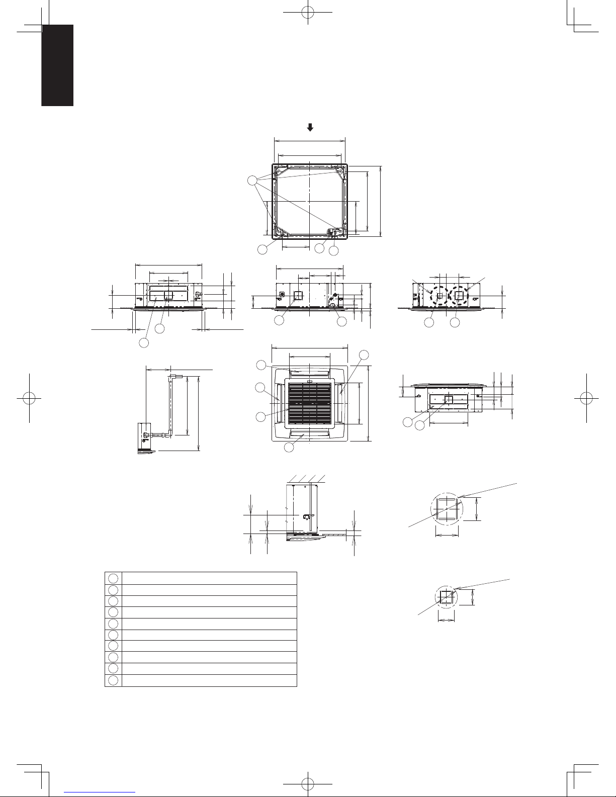
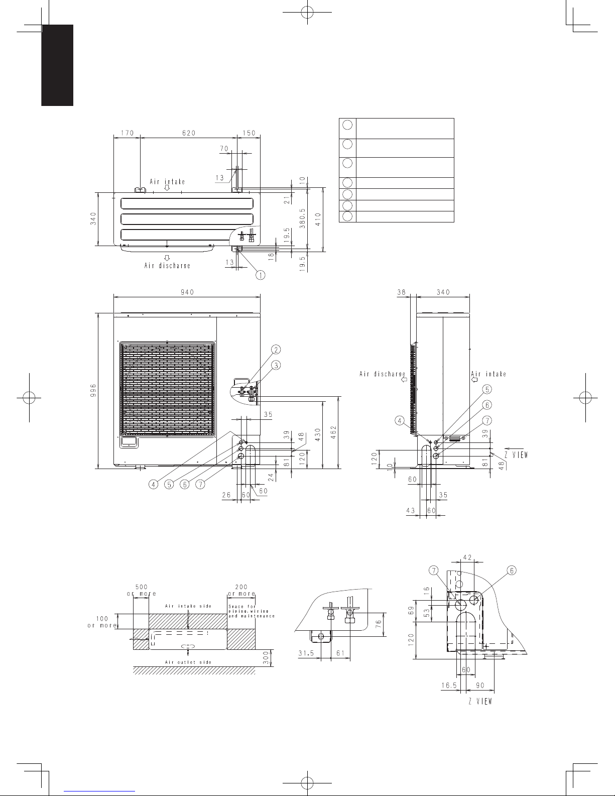
1-2. Dimensional Data
(A) Indoor Units: S-60PU1R5 / 71PU1R5
1
2
3
4
5
6
7
8
9
10
Air intake
Discharge outlet
Refrigerant tubing (liquid tube) ø9.52 (flared)
Refrigerant tubing (gas tube) ø15.88 (flared)
Drain tube connection port VP25 (outer dia. ø32)
Power supply port
Discharge duct connection port (ø150)
Vaporization-type humidifier (optional) installation area
Suspension bolt hole (4-12×30 elongated hole)
Fresh air intake duct connection port (ø100) *
345
9
5
3
4
7
7
8
6
2
2
2
2
1
10
7
7
8
421
(411)
745
(Suspension bolt pitch)
860~910
(Ceiling opening dimensions)
160
33.5
50121
42
840
50
271
145
160
16082
unit: mm
130
480
130
167
480
2
840
167
124
514
950
515
950
95
124
95
180
30
18
118
256
115
115
80
80
* Necessary to provide optional air intake kit.
<Filter dimension>
520 × 520 × 16
The length of the suspension bolts
should be selected so that there is
a gap of 30 mm or more below the
lower surface of the ceiling (18 mm
or more below the lower surface of
the main unit), as shown in the
figure at right. If the suspension
bolt is too long, it will contact
the ceiling panel and the unit
cannot be installed.
Raise dimension of drain tube
Detailed view Z
Detailed view Y
View X
X
ZY
860~910
786
(Ceiling opening dimensions)
(Suspension bolt pitch)
Less than 35
Less than 300
Less than 670
Less than 850
Less than 35
4 - ø3 burring hole
4 - ø3 burring hole
ø16
2
ø113
Sec1.indb15Sec1.indb15 2012/03/0717:29:572012/03/0717:29:57
1-16
1
(A) Indoor Units: S-100PU1R5 / 125PU1R5 / 140PU1R5
unit: mm
30
18
118
187
2
480
840
167
187
180
319
95
80
80
1
2
3
4
5
6
7
8
9
10
Air intake
Discharge outlet
Refrigerant tubing (liquid tube) ø9.52 (flared)
Refrigerant tubing (gas tube) ø15.88 (flared)
Drain tube connection port VP25 (outer dia. ø32)
Power supply port
Discharge duct connection port (ø150)
Vaporization-type humidifier (optional) installation area
Suspension bolt hole (4-12×30 elongated hole)
Fresh air intake duct connection port (ø100) *
* Necessary to provide optional air intake kit.
<Filter dimension>
520 × 520 × 16
115
115
Detailed view Z
Detailed view Y
4 - ø3 burring hole
4 - ø3 burring hole
ø162
ø113
The length of the suspension bolts
should be selected so that there is
a gap of 30 mm or more below the
lower surface of the ceiling (18 mm
or more below the lower surface of
the main unit), as shown in the
figure at right. If the suspension
bolt is too long, it will contact
the ceiling panel and the unit
cannot be installed.
7
8
130
480
130
167
95
View X
Less than 300
Less than 670
Less than 850
2
2
2
1
514
950
515
950
2
X
10
7
160
16082
ZY
7
6
160
33.5
50
121
42
840
50
271
145
7
8
Less than 35Less than 35
345
9
5
3
4
421
(411)
745
(Suspension bolt pitch)
860~910
(Ceiling opening dimensions)
860~910
786
(Ceiling opening dimensions)
(Suspension bolt pitch)
1-2. Dimensional Data
Sec1.indb16Sec1.indb16 2012/03/0717:29:572012/03/0717:29:57

1-17
1
1-2. Dimensional Data
(A) Indoor Units: Ducted Type
S-60PE1R5 / S-71PE1R5 / S-100PE1R5 / S-125PE1R5 / S-140PE1R5
POSITION OF SUSPENSION BOLT
S-60PE1R5 1060
1060
110 0
110 0
540
540
700
unit : mm
700
S-71PE1R5
S-100PE1R5
S-125PE1R5
S-140PE1R5
S-60PE1R5
TYPE
130
195
33.1
35.7
290
360
118
ABCD
unit : mm
50
260 38.2 430 1215
S-71PE1R5
S-100PE1R5
S-125PE1R5
S-140PE1R5
Sec1.indb17Sec1.indb17 2012/03/0717:29:572012/03/0717:29:57
1-18
1
1-2. Dimensional Data
(B) Outdoor Units: U-60PE1R5 / U-71PE1R5
1
2
3
4
5
6
7
Mounting hole (4-R6.5),
anchor bolt: M10
Refrigerant piping (liquid pipe),
flared connection (ø9.52)
Refrigerant piping (gas pipe),
flared connection (ø15.88)
Electrical wiring port (
ø13
)
Electrical wiring port (
ø22
)
Electrical wiring port (
ø27
)
Electrical wiring port (
ø35
)
unit: mm
Sec1.indb18Sec1.indb18 2012/03/0717:29:572012/03/0717:29:57
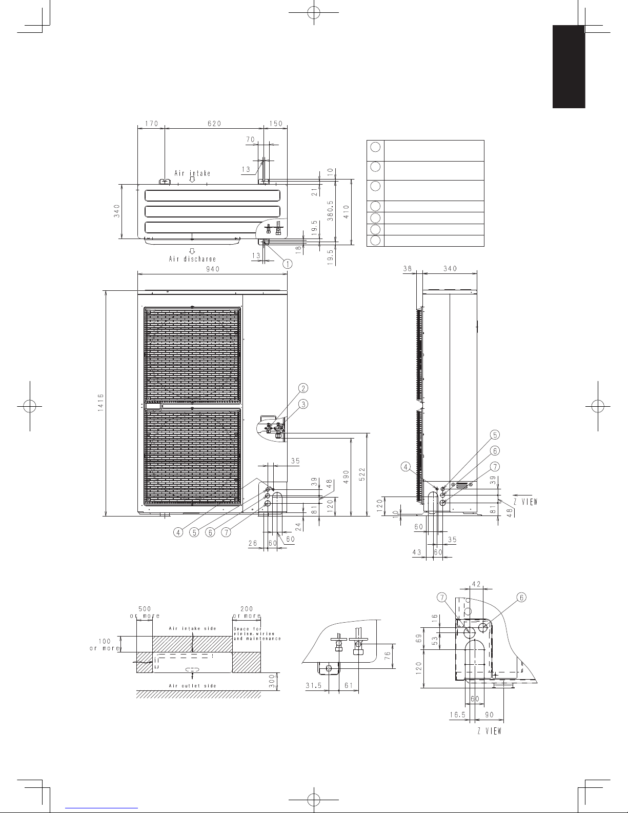
1-19
1
1-2. Dimensional Data
(B) Outdoor Units: U-100PE1R5 / U-125PE1R5 / U-140PE1R5
U-100PE1R8 / U-125PE1R8 / U-140PE1R8
1
2
3
4
5
6
7
Mounting hole (4-R6.5),
anchor bolt: M10
Refrigerant piping (liquid pipe),
flared connection (ø9.52)
Refrigerant piping (gas pipe),
flared connection (ø15.88)
Electrical wiring port (
ø13
)
Electrical wiring port (
ø22
)
Electrical wiring port (
ø27
)
Electrical wiring port (
ø35
)
unit: mm
Sec1.indb19Sec1.indb19 2012/03/0717:29:572012/03/0717:29:57
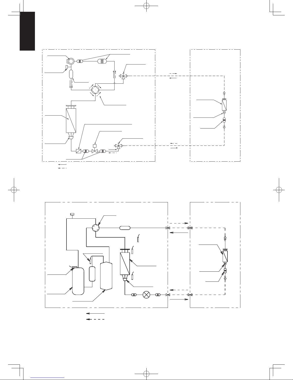
1-20
1
M
PECP
ø15.88
ø15.88
ø9.52
ø9.52
Compressor
Compressor
Heat
exchanger
Heat
EC
P
Defrost Temp
Expantion
valve
Cooling cycle
Heating cycle
exchanger
Heat exchanger
Temp Thermistor
Temp Thermistor
Outdoor-air
Discharge Temp
Thermistor
Suction Temp
Thermistor
4-way
valve
High pressure
switch
High pressure
switch
Thermistor
Accumulator
Accumulator
Gas line
service valve
Muffl er
Muffl er
4-way valve
Electronic ref.
control valve
Liquid line
service valve
Cooling cycle
Heating cycle
Strainer
Strainer Strainer
Heat
exchanger
Heat
exchanger
Strainer
Distributor
Strainer
Distributor
Distributor
Distributor
Freeze-prevention coil
(Attached to the heat exchanger)
1-3. Refrigerant Flow Diagram
Indoor Unit:
Outdoor Units: U-60PE1R5 / U-71PE1R5
Indoor Unit:
Outdoor Units: U-100PE1R5 / U-125PE1R5 / U-140PE1R5
U-100PE1R8 / U-125PE1R8 / U-140PE1R8
Sec1.indb20Sec1.indb20 2012/03/0717:29:572012/03/0717:29:57
1-21
1
1-4. Operating Range
Temperature Indoor air intake temp. Outdoor air intake temp.
Cooling
Maximum 32°C DB / 25°C WB 46°C DB
Minimum 18°C DB / 14°C WB -15°C DB
Heating
Maximum 30°C DB / − WB 24°C DB/18°C WB
Minimum 16°C DB / − WB -20°C DB / -20°C WB
Sec1.indb21Sec1.indb21 2012/03/0717:29:572012/03/0717:29:57

1-22
1
1-5. Capacity Correction Graph According to Temperature Condition
U-60PE1R5 (For 50 Hz)
Cooling capacity ratio (maximum capacity) Heating capacity ratio (maximum capacity)
Input coefficient (%) Capacity coefficient (%)
Outdoor air intake temp ( °C DB)
20
40
60
80
100
120
140
20
40
60
80
100
120
140
-15
-5 5 15 25 35 45
Input coefficient (%)
40
60
80
100
120
Outdoor air intake temp ( °C WB)
-20 -15 -10 -5 0 5 10 15
Capacity coefficient (%)
20
40
60
80
100
120
140
Cooling
Capacity (kW)
Input coefficient (%)
0
20
40
60
80
100
120
140
160
180
Capacity (kW)
Heating
Input coefficient (%)
0
20
40
60
80
100
120
140
160
180
0246810
135%
1002468
137%
Indoor air intake temp ( °C DB)
Indoor air intake temp ( °C DB)
Indoor air intake temp ( °C WB)
Indoor air intake temp ( °C WB)
22°CWB
19°CWB
16°CWB
22°CWB
19°CWB
16°CWB
16 °CD
B
20 °CD
B
24 °CD
B
16 °CD
B
20 °CD
B
24 °CD
B
Outdoor unit heating capacity correction cofficient during of frosting/defrosting (RH approximately 85%)
Outdoor intake air
temperature °C WB
-20 -15 -10 -9 -8 -7 -6 -5 -4 -3 -2 -1 0 1 2 3 4 5 6
Correction coefficient
1.0 1.0 0.97 0.96 0.96 0.95 0.94 0.91 0.89 0.88 0.87 0.87 0.87 0.88 0.89 0.91 0.92 0.95 1.0
To calculate the heating capacity with consideration for frosting/defrosting operation, multiply the heating capacity
found from the capacity graph by the correction coefficient from the table above.
Sec1.indb22Sec1.indb22 2012/03/0717:29:572012/03/0717:29:57

1-23
1
1-5. Capacity Correction Graph According to Temperature Condition
U-71PE1R5 (For 50 Hz)
Cooling capacity ratio (maximum capacity) Heating capacity ratio (maximum capacity)
Input coefficient (%) Capacity coefficient (%)
Outdoor air intake temp ( °C DB)
20
40
60
80
100
120
140
20
40
60
80
100
120
140
-15
-5 5 15253545
Input coefficient (%)
040
60
80
100
120
Outdoor air intake temp ( °C WB)
-20 -15 -10 -5 0 5 10 15
Capacity coefficient (%)
20
40
60
80
100
120
140
Cooling
Capacity (kW)
Input coefficient (%)
0
20
40
60
80
100
120
140
160
180
Capacity (kW)
Heating
Input coefficient (%)
0
20
40
60
80
100
120
140
160
180
0246810 1002468
147%
145%
22°CWB
19°CWB
16°CWB
22°CWB
19°CWB
16°CWB
Indoor air intake temp ( °C WB)
Indoor air intake temp ( °C WB)
16 °CDB
20 °CDB
24 °CDB
16 °CDB
20 °CDB
24 °CDB
Indoor air intake temp ( °C DB)
Indoor air intake temp ( °C DB)
Outdoor unit heating capacity correction cofficient during of frosting/defrosting (RH approximately 85%)
Outdoor intake air
temperature °C WB
-20 -15 -10 -9 -8 -7 -6 -5 -4 -3 -2 -1 0 1 2 3 4 5 6
Correction coefficient
1.0 1.0 0.97 0.96 0.96 0.95 0.94 0.91 0.89 0.88 0.87 0.87 0.87 0.88 0.89 0.91 0.92 0.95 1.0
To calculate the heating capacity with consideration for frosting/defrosting operation, multiply the heating capacity
found from the capacity graph by the correction coefficient from the table above.
Sec1.indb23Sec1.indb23 2012/03/0717:29:582012/03/0717:29:58
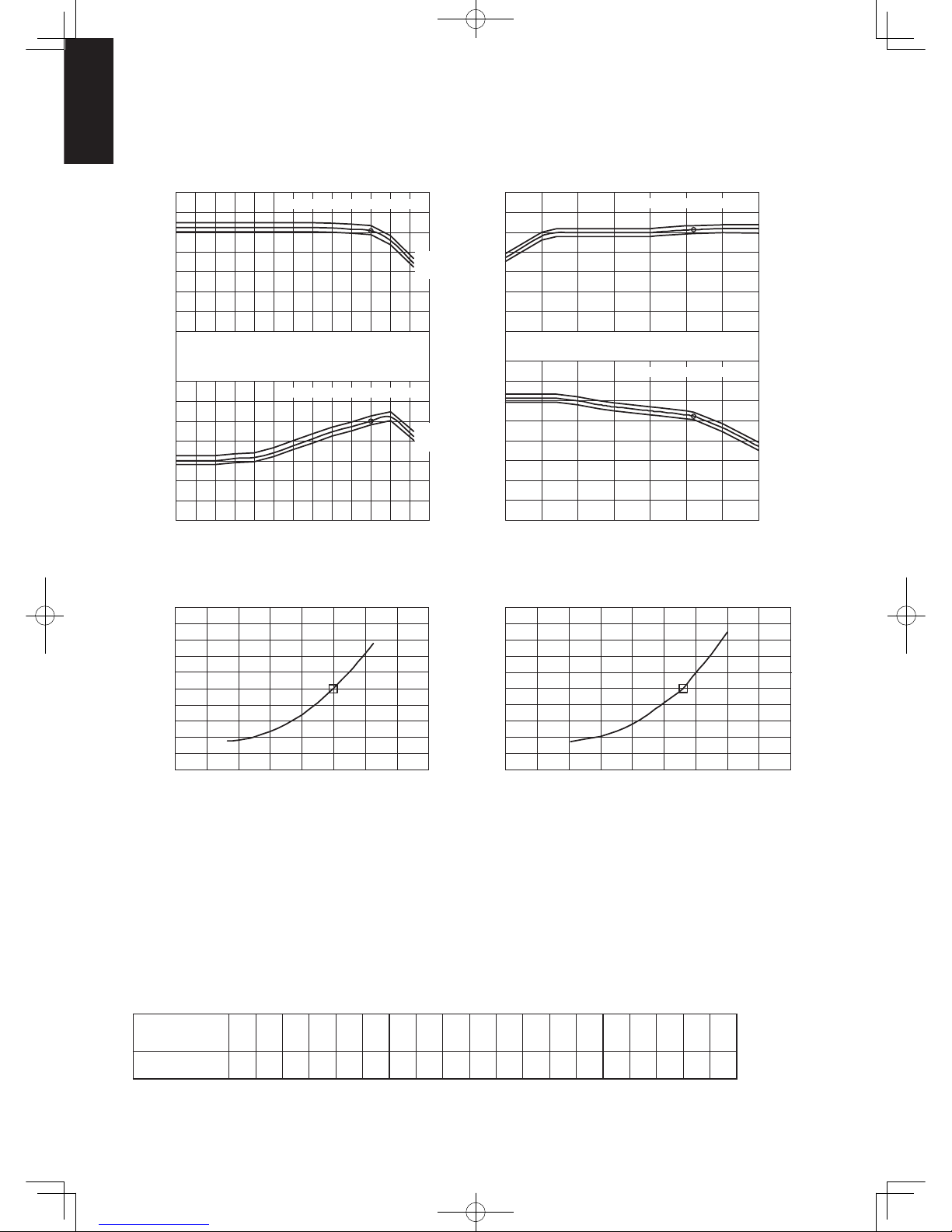
1-24
1
1-5. Capacity Correction Graph According to Temperature Condition
U-100PE1R5 (For 50 Hz)
Cooling capacity ratio (maximum capacity) Heating capacity ratio (maximum capacity)
Cooling Heating
Input coefficient (%) Capacity coefficient (%)
Input coefficient (%)
Capacity coefficient (%)
Outdoor air intake temp ( °C WB) Outdoor air intake temp ( °C DB)
Capacity (kW) Capacity (kW)
Input coefficient (%)
Input coefficient (%)
0
20
40
60
80
100
120
140
160
180
200
0
20
40
60
80
100
120
140
160
180
200
02 46 810121416
0 2 4 6 8 10 12 14 16 18
0
20
40
60
80
100
120
140
0
20
40
60
80
100
120
140
-15
-5 5 15253545
22°CWB
19°CWB
16°CWB
22°CWB
19°CWB
16°CWB
0
20
40
60
80
100
120
140
0
20
40
60
80
100
120
140
160
-20 -15 -10 -5 0 5 10 15
16 °CDB
20 °CDB
24 °CDB
16 °CDB
20 °CDB
24 °CDB
Indoor air intake temp ( °C WB)
Indoor air intake temp ( °C WB)
Indoor air intake temp ( °C DB)
Indoor air intake temp ( °C DB)
Outdoor unit heating capacity correction cofficient during of frosting/defrosting (RH approximately 85%)
Outdoor intake air
temperature °C WB
-20 -15 -10 -9 -8 -7 -6 -5 -4 -3 -2 -1 0 1 2 3 4 5 6
Correction coefficient
1.0 1.0 0.97 0.96 0.96 0.95 0.94 0.91 0.89 0.88 0.87 0.87 0.87 0.88 0.89 0.91 0.92 0.95 1.0
To calculate the heating capacity with consideration for frosting/defrosting operation, multiply the heating capacity
found from the capacity graph by the correction coefficient from the table above.
Sec1.indb24Sec1.indb24 2012/03/0717:29:582012/03/0717:29:58

1-25
1
1-5. Capacity Correction Graph According to Temperature Condition
U-125PE1R5 (For 50 Hz)
Cooling capacity ratio (maximum capacity) Heating capacity ratio (maximum capacity)
Input coefficient (%)
Capacity coefficient (%)
Input coefficient (%) Capacity coefficient (%)
Outdoor air intake temp ( °C DB)
0
20
40
60
80
100
120
140
0
20
40
60
80
100
120
140
-15
-5 5 15253545
22°CWB
19°CWB
16°CWB
22°CWB
19°CWB
16°CWB
Indoor air intake temp ( °C WB)
Indoor air intake temp ( °C WB)
0
20
40
60
80
100
120
140
0
20
40
60
80
100
120
140
Indoor air intake temp ( °C DB)
Indoor air intake temp ( °C DB)
Outdoor air intake temp ( °C WB)
-20 -15 -10 -5 0 5 10 15
Cooling Heating
Capacity (kW)
02 46 810121416
Input coefficient (%)
0
20
40
60
80
100
120
140
160
180
200
Input coefficient (%)
0
20
40
60
80
100
120
140
160
180
200
Capacity (kW)
0 2 4 6 8 10 12 14 16 18
16 °CDB
20 °CDB
24 °CDB
16 °CDB
20 °CDB
24 °CDB
Outdoor unit heating capacity correction cofficient during of frosting/defrosting (RH approximately 85%)
Outdoor intake air
temperature °C WB
-20 -15 -10 -9 -8 -7 -6 -5 -4 -3 -2 -1 0 1 2 3 4 5 6
Correction coefficient
1.0 1.0 0.97 0.96 0.96 0.95 0.94 0.91 0.89 0.88 0.87 0.87 0.87 0.88 0.89 0.91 0.92 0.95 1.0
To calculate the heating capacity with consideration for frosting/defrosting operation, multiply the heating capacity
found from the capacity graph by the correction coefficient from the table above.
Sec1.indb25Sec1.indb25 2012/03/0717:29:582012/03/0717:29:58
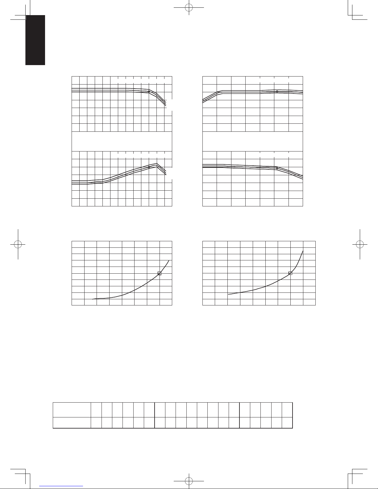
1-26
1
1-5. Capacity Correction Graph According to Temperature Condition
U-140PE1R5 (For 50 Hz)
Cooling capacity ratio (maximum capacity) Heating capacity ratio (maximum capacity)
Input coefficient (%) Capacity coefficient (%)
Outdoor air intake temp ( °C DB)
0
20
40
60
80
100
120
140
0
20
40
60
80
100
120
140
-15
-5 5 15253545
22°CWB
19°CWB
16°CWB
22°CWB
19°CWB
16°CWB
Indoor air intake temp ( °C WB)
Indoor air intake temp ( °C WB)
Input coefficient (%)
0
20
40
60
80
100
120
140
Outdoor air intake temp ( °C WB)
-20 -15 -10 -5 0 5 10 15
Capacity coefficient (%)
0
20
40
60
80
100
120
140
16 °CDB
20 °CDB
24 °CDB
16 °CDB
20 °CDB
24 °CDB
Indoor air intake temp ( °C DB)
Indoor air intake temp ( °C DB)
Cooling
Capacity (kW)
02 46 810121416
Input coefficient (%)
0
20
40
60
80
100
120
140
160
180
200
Capacity (kW)
024681012141618
Heating
Input coefficient (%)
0
20
40
60
80
100
120
140
160
180
200
Outdoor unit heating capacity correction cofficient during of frosting/defrosting (RH approximately 85%)
Outdoor intake air
temperature °C WB
-20 -15 -10 -9 -8 -7 -6 -5 -4 -3 -2 -1 0 1 2 3 4 5 6
Correction coefficient
1.0 1.0 0.97 0.96 0.96 0.95 0.94 0.91 0.89 0.88 0.87 0.87 0.87 0.88 0.89 0.91 0.92 0.95 1.0
To calculate the heating capacity with consideration for frosting/defrosting operation, multiply the heating capacity
found from the capacity graph by the correction coefficient from the table above.
Sec1.indb26Sec1.indb26 2012/03/0717:29:582012/03/0717:29:58
 Loading...