

Page 1

Operating
Instructions
Multi-Scan Color Monitor
TM
S ¿«f f 8T S S'^
.11]®
Pwwiionio
A - A
Panasonic
These Operating Instructions are for units for sale and use in
the United States of America and Canada only.
Read these instructions completely before operating this display monitor.
Page 2

Page 3

IMPORTANT NOTICE CONCERNING POWER CORD SELECTION
The power cord for this unit has been packed separately and has been selected according to the country of destination and
must be used to prevent electric shock. Use the following guidelines if it is necessary to replace the original cord set.
The female receptacle of the cord set must meet CEE-22 requirements and will look tike Figure 1:
WICHTIGE INFORMATION BEZÜGLICH DES ZU BENUTZENDEN NETZKABELS
Das Netzkabel für diese Geräteeinheit wird separat verpackt geliefert und entspricht jeweils den landesspezifischen
Anforderungen. Aus Gründen der Unfallverhütung ist die Benutzung dieses Netzkabeis zwingend. Beachten Sie bitte folgende
Hinweise, wenn ein Austausch des Originalkabeis erforderlich ist. Der geräteseitige Stecker des Netzkabels muß den CEE-22
Anforderungen sowie dem in Abb. 1 gezeigten Beispiel entsprechen.
AVISO IMPORTANTE RESPECTO A LA SELECCION DEL CABLE DE SUMINISTRO ELECTRICO
El cable de suministro eléctrico de esta unidad ha sido empacado en forma separada, ha sido seleccionado de acuerdo con el
país de destino y debe ser usado para prevenir sobrecargas eléctricas. Use las gulas descritas a continuación, si es necesario
reemplazar el cable original. El receptáculo hembra del cable debe cumplir los requerimientos CEE-22 y se verá como aparece
en la Figura 1.
NOTICE IMPORTANTE CONCERNANT LE CHOIX DU CORDON D’ALIMENTATION
Le cordon d'alimentation conçu pour cette unité a été conditionné dans un emballage distinct et il a été choisi en fonction du
pays de destination. Son utilisation vise à vous prévenir de toute décharge électrique. Si vous devez remplacer le cordon initial,
veuillez suivre les informations ci-dessous mentionnées. Le receptacle femelle du cordon doit satisfaire aux normes CEE-22 et
comporter les caractéristiques présentées au schéma 1.
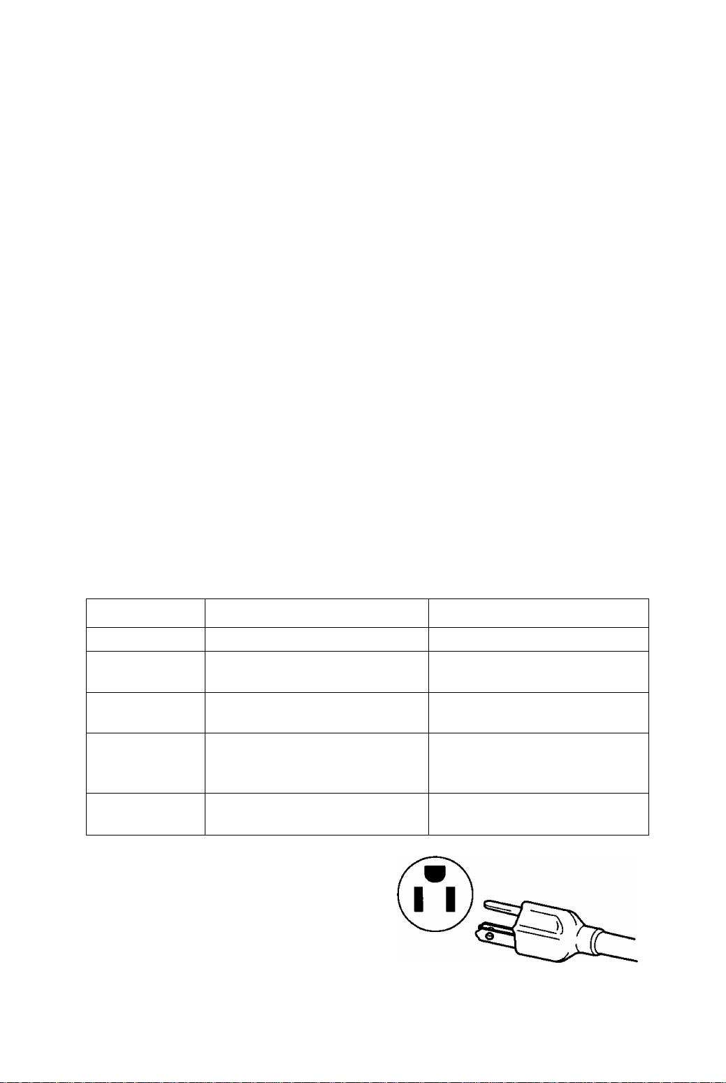
For the United States and Canada
In the United States and Canada the male plug is a NEMA 5-15 style (Figure 2) and is UL listed and CSA labelled. For units
which are mounted on a desk or table, type SVT or SJT cord sets may be used. For units which sit on the floor, only SJT type
cord sets may be used. The cord set must be selected according to the current rating for your unit. Please consult Table A for
the selection criteria for power cords used in the United States and Canada. (The cord set is marked with its Cord Type.)
U.S.A. und Kanada:
ln den U.S.A. und Kanada verfügt das Kabel netzseitig über einen Stecker des Typs NEMA 5-15 (Abb. 2), der den UL-
Sicherheitsbestimmungen entspricht und die Markierung CSA trägt. Für Geräte, die auf einer Arbeitsfläche wie Tisch oder
Schreibtisch installiert sind, können Netzkabel des Typs SVT oder SJT benutzt werden. Die Auswahl des Netzkabeis muß
gemäß dem für das Gerät zutreffenden Stromaufnahme-Nennwert erfolgen. Tabelle A enthält eine Aufstellung der Kriterien, die
bei der Wahl des Netzkabels in den U.S.A. und Kanada zu berücksichtigen sind.(Der Kebelsatz ist mit dem Kapbeltyp
markiert.)
Para los Estados Unidos y Canadá
En los Estados Unidos y en Canadá el conector macho es estilo NEMA 5-15 (Figura 2), está listado UL y etiquetado CSA. Para
las unidades que están montadas sobre un escritorio o sobre una mesa, debe usarse el cable tipo SVT o SJT. Para unidades
que están sobre el piso, sólo se debe usar el cable tipo SJT. El cable debe ser seleccionado de acuerdo al tipo de voltaje de su
unidad. Consulte en la Tabla A los criterios de selección de los cables de suministro eléctrico usados en los Estados Unidos y
en Canadá.(EI juego de cables está marcads con su tipo de cables.)
Etas-Unis et Canada
Aux Etats-Unis ainsi qu'au Canada, la prise mâle est de type NEMA 5-15 (schéma 2); elle est mentionnée dans la liste UL et
porte la mention CSA. En ce qui concerne les unités qui sont placées sur une table ou sur un bureau, il est possible d’utiliser
des cordons de type SVT ou SJT, Quant aux unités qui sont placées à môme le sol. seuls des cordons de type SJT peuvent
ótre utilisés. Le choix du cordon doit s’effectuer en fonction de l'ampérage de votre unité. Veuillez consulter le tableau A suivant
les critères de selection des cordons d’alimentation utilisés aux Etats-Unis et au Canada.(Le jeu de cordon est marqué du type
du cordon.)
Page 4
For European Countries:
In Europe you must use a cord set which Is appropriate for the receptacles In your country. The cord set Is HARCertlfled, and the mark A HAR k will appear on the outer sheath, or on the Insulation of one of the Inner conductors.
If you have any questions concerning the proper power cord to use, please consult with the dealer from whom you purchased
your unit.
Europa:
In den europäischen Ländern Ist das für den AnschluB an das Jeweilige Netz erforderliche Kabel zu verwenden. Das
Kabel muD den HAR-Anforderungen entsprechen und auf der Außenisolierung oder auf der Isolierung einer der
Kabeladern die Markierung 4 HAR k aufwelsen.
Sollten Sie hinsichtlich der Anwendung des richtigen Kabels irgendwelche Fragen haben, so konsultieren Sie bitte Ihren
Händler, von dem Sie Ihr Gerät erworben haben.
Para los países europeos:
En Europa debe usar el cable apropiado al receptáculo usado en su país. El cable es HAR certificado y la marca
4 HAR ^ aparecerá en el forro externo o en la cubierta aislante de uno de los conductores internos.
Si tiene dudas acerca del cable apropiado que se debe usar, consulte la tienda donde adquirió su unidad.
Pays européens:
En Europe, voua devez utiliser des cordon appropriés aux prises de votre pays. Les cordons doivent être de marque
4 HAR k- et celle-ci doit apparaître sur la gaine plastique externe ou sur la partie Isolante d’un des conducteurs
Internes.
Si vous avez des questions concernant le bon cordon à utiliser, vous êtes priés de consulter le concessionnaire chez qui vous
avez acheté votre appareil.
Table A Tabelle A Tabla A Tableau A
Gord Type Size of Conductors In Cord
Kabeltyp
Größe der Kabeladern
Tipo de cable Tamaño de los conductores del
cable
Type de cordon
Taille des conducteurs dans le
cordon
SJT
18AWG
16AWG
14AWG
SVT
18AWG
17AWG
Maximum Current Rating of Unit
Max. Stromaufnahme des Geräts
Máximo voltaje de acuerdo a la
unidad
Ampérage maximum de l'unitó
10Amps
12Amps
12Amps
tOAmps
12Amps
Figure 1 Abb. 1 Figura 1 Schéma 1 Figure 2 Abb. 2 Figura 2 Schéma 2
Page 5

Page 6
Federal Communications Commission Requirements
This equipment has been tested and found to comply with the limits for Class B digital devices, pursuant
to Part 15 of the FCC Rules. These limits are designed to provide reasonable protection against harmful
interference in a residential installation. This equipment generates, uses, and can radiate radio frequency
energy and, if not installed and used in accordance with the instructions, may cause harmful interference
to radio communications. However, there is no guarantee that interference will not occur in a particular
installation. If this equipment does cause harmful Interference to radio or television reception, which can
be determined by turning the equipment off and on, the user is encouraged to try to correct the interfer
ence by one or more of the following measures:
- Reorient or relocate the receiving antenna.
- Increase the separation between the equipment and receiver.
- Connect the equipment into an outlet on a circuit different from that to which the receiver is
connected.
- Consult the dealer or an experienced radio/TV technician for help.
FCC Warning:
To assure continued FCC compliance, the user must use the provided grounded power supply
cord and shielded Interface cable with bonded ferrite cores. If BNC cable is going to be used,
use only shielded BNC (5) cable. Also, any unauthorized changes or modifications to this moni
tor would void the user’s authority to operate this device.
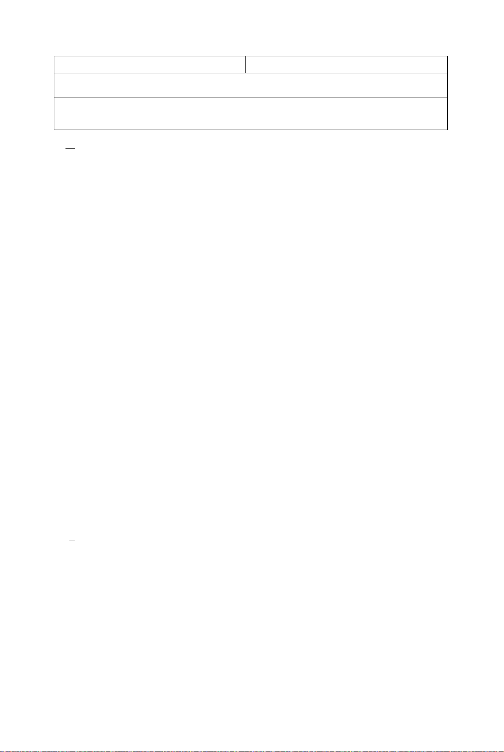
CE Conformity
This device complies with the requirements of the EEC directive 89/336/EEC as
amended by 92/31/EEC and 93/68/EEC Art. 5 with regard to “Electromagnetic
C€
Required item Relative to Standard Value
EM I
ESD
RADIATED RF
TRANSIENT F/B
LINE HARMONICS
#1 : Satisfies standards with no problems in performance and reliability.
#2 : Effects may appear temporarily on the screen but there will be no problem in reliability.
#3: There is fear of the product breaking down.
#4; If a signal cable other than that specified is used, it may be the cause of electromagnetic
Handle correctly in accordance with the instruction manual.
EMI: Electromagnetic Interference ESD : Electrostatic Discharge
RF : Radio Frequency F/B : Fast Burst
compatibility", and 73/23/EEC as amended by 93/68/EEC Art. 13 with regard to "Safety”.
Relative to those Exceeding Standard ValueRemarks
#1
#2 #3
#1 #3
#1
#1
wave interruption of peripheral devices.
To assure continued CE compliance the user must use the provided 1.5 m shielded
video signal cable with bonded ferrite cores at both ends of the cable.
1
#3
Z
#4
____
^
As an Energy Star* partner, Panasonic Computer Peripheral Company has determined that this product
meets the Energy Star® guidelines for energy efficiency.
Page 7

I
Danger
To avoid the risk of severe electrical shock including death, do not remove
covers (or back) of monitor. No user serviceable parts are inside.
Refer servicing to qualified service personnel.
I
Warnings
To prevent risk of electric shock and possible fire:
Never place any object on the monitor, AC line cord, or cause the cords to make
sharp bends, or otherwise do anything that can affect the integrity of the cords.
Always remove the line cord from the socket by holding the plug, not the cord.
Do not place anything containing any liquid (even a wet or damp cloth) on the
monitor as the introduction of fluids can create an electrical hazard. Do not
expose the monitor to rain or moisture.
Do not place the monitor with less than the recommended clearance (see
Precautions, 1 Installation Page 2). Do not block the ventilation openings with
anything. Do not insert any objects into the ventilation openings.
Customer’s Record
The serial number of this product is printed on its back cover label.
Note this serial number in the space provided and retain this booklet as a permanent record of
your purchase to aid in identification of the unit in the event of theft or loss.
Model number : Si 10
Serial number
Table of Contents
Important Notice Concerning Power Cord Selection
Federal Communications Commission Requirements......................iv
CE Conformity......................................................................................iv
Danger..................................................................................................1
Warnings...............................................................................................1
Customer’s Record..............................................................................1
Table of Contents.................................................................................1
Precautions 1)lnstallation.....................................................................2
Precautions 2)Usage
Precautions 3)Product Care................................................................2
Features................................................................................................3
Specifications........................................................................................4
Installation.............................................................................................5
Pin Assignment
External View
On-Screen Adjustment.........................................................................8
Operation .............................................................................................9
Power Management System
Memories............................................................................................14
Timing Specifications.........................................................................15
Trouble Shooting ...............................................................................18
Technical Support
Index .................................................................................................. 19
Notice for Germany............................................................................20
Notice for Japan.................................................................................20
...................................................................................
...........................................................................
....................................................................................
.............................................................
.............................................................................
..........................
7
14
19
i
2
6
ALL PRODUCT/BRAND NAMES ARE TRADEMARKS OR REGISTERED TRADEMARKS OF THE RESPECTIVE HOLDERS.
© 1997 MATSUSHITA ELECTRIC INDUSTRIAL Co., Ltd.
-1 -
Page 8

Precautions
1) Installation
• Install the monitor in a well ventilated place. Avoid exposing to direct sunlight, a
heater, or any other heat source. Heat will adversely affect the cabinet and the
parts inside.
• Position the display unit so that the holes in the cabinet will not be blocked during use.
• Keep the display unit away from the kitchen, bathroom, washing machine, or other
sources of exposure to water, steam or moisture.
• In order to use the display unit safely, use only the supplied AC line cord. The AC line
cord must be used with a properly grounded and polarized power supply socket. The
AC line cord supplied is for the USA (UL) and Canada (CSA) for use with the display
unit. For use in other countries, make sure the AC line cord meets the safety
standards of the country.
• Place the AC line cord where it will not be subject to stress.
• Use only Panasonic provided accessories or the exact equivalent.
2) Usage
• Pulling on the AC line cord or VGA Signal Cable can damage the display unit
(monitor) and can cause the unit to fall and possibly cause personal injury.
• Receiving trouble.
If there is a television set or other display unit nearby, keep your display unit as far
away from it as possible. Mutual interlerence can cause image distortion or noise.
• Long exposure to rubber or vinyl products can stain the cabinet.
• Keep the monitor from physical shock when moving. Be careful of the Cathode Ray
Tube (CRT).
• Do not place anything on the monitor.
• Also take good care of the power cord:
Do not place any objects on the power cable. Do not attempt to extend, shorten or tie
it into a knot.
3) Product Care
• Prior to cleaning your display unit, disconnect the AC line cord and the VGA Signal
Cable or BNC Cable from the display unit.
• Use a clean, soft, dry cloth to clean the outside of the monitor or the CRT surface.
If the monitor or CRT surface is very dirty, wet a clean, soft cloth with neutral
detergent (such as dishwashing detergent) and water, squeeze it tight until almost dry,
wipe the monitor or CRT surface with it, and finish by wiping with a clean dry cloth.
Do not use any solvents.
• Do not rub or strike the monitor with anything hard or harsh as this may scratch, mar
or damage the monitor permanently.
• Do not use a chemical duster or polish-cleaner because it can adversely affect the unit
and peel the paint coat.
-2-
Page 9

Features
Digital adjustment using the on-screen display
1)
• The on-screen menu is available in 5 languages. English, French, German, Italian or Spanish can be
selected.
• Custom adjustments can be made quickly and easily through the on-screen menu utilizing four buttons on
the front panel.
• The on-screen main menu allows these adjustments to be made easily by scrolling through the icons to
select an adjustment menu. The choice bar is located at the bottom of the main menu and it shows the
currently selected adjustment menu’s name.
• Set the on-screen menus at any one of six locations on the display screen.
2)
The Plug & Play S110 is a DDC 1/2B* compatible monitor that uses VESA* {Video Electronics Standards
Association) DDC ^(Display Data Channel) standard. This allows the S110 to inform a compatible host of
its capabilities which meet the Microsoft* / Intel* Plug & Play Definition used by Windows*95.
Power Management
3)
• A power management circuit conforming to the VESA DPMS standard is incorporated into the monitor.
Power consumption of the monitor can be lowered when using it in combination with a video board that
meets the DPMS standard.
• This product conforms to the Energy STAR*program.
As an Energy Star* partner, Panasonic Computer Peripheral Company has determined that this product
meets the Energy Star*guidelines for energy efficiency.
4)
Environmentally Friendly
• All the plastic parts are recyclable.
5)
Low emissions and static prevention
• The display unit meets the strict Swedish (SWEDAC) MPR II guidelines for lower ELF and VLF magnetic
fields and alternating electric fields.
• The S110 meets the requirements of Swedish confederation of professional employees TCO'92.
• Anti-static coating of the cathode ray tube (CRT) reduces electrostatic charge buildup. This prevents
electrostatic shocks when touching the CRT screen and reduces dust buildup.
Color adjusting function
6)
• The white balance of an image can be adjusted as desired by individual adjustment of the red(R) and
green(G) and blue(B) signals. This feature enables color matching.
• The white reference color temperature is 9300K + 8 MPCD, 7500K, 6500K, 5000K, or a user color can be
selected. For example, the monitor colors can be adjusted to match the colors of output generated on a
color printer.
PanaSync digital multi-scan
7)
• Horizontal frequencies of 30 kHz to 95 kHz and vertical frequencies of 50 to 180 Hz can be automatically
tracked. The display unit is suited to VGA, SVGA, VESA, and high-resolution video boards of 1600(H) x
1200(V)/75 Hz.
• Eight timing (1 preset and 7 reservation) selections have been preset by the factory for image size and
position. In addition there are 13 user programmable selections of timing.
Self-test menu
8)
• The display unit can be checked via the self-test menu displayed on the screen. This menu can be
accessed without a computer.
DQ-DAF Electron Gun with Hyperbolic focus compensation circuit
9)
• The exclusive DQ-DAF electron gun with a hyperbolic focus compensation circuit that controls the electron
beam is combined with an invar mask to display fine images over the entire area on the 21 inch
(20.0inch/50.8cm viewable), 0.25mm dot pitch, flat and square screen.
10) Other features
• Automatic selection of synchronized input signals (separate, composite or sync-on-green).
• An ergonomically designed tilt and swivel base to complement virtually any office design. The pan angle is
90 degrees at the right and left, and the tilt angle is 13 degrees up and 4 degrees down.
* VESA DDC
The S110 is a VESA DDC 1/2B type of display. The S110 is capable of continuously transmitting its EDID
(Extended Display Identification) using a uni-directional DDC1 communications channel. In addition, the
S110 can respond to a request for EDID, or complete VDtF (Video Display Interface), to be transmitted using
DDC 2, Level B commands.
The EDID data contains the display identity and the basic display specifications. The VDIF data contains full
display specifications as defined in the VESA VDIF standard. If a DDC 2 capable host is detected by the
S110, it will switch to a bi-directional DDC 2 communications channel.
As required by the VESA DDC standard, once the S110 has switched from DDC 1 to DDC 2 it is incapable of
switching from DDC 2 back to DDC 1 unless the power is turned off.
-3 -
Page 10
Specifications
CRT Size
Dot-pitch 0.25 mm (H : 0.218mm / V : 0.130mm )
Phosphor
Surface treatment
Input signals Video signaling
Signal level 0.7 Vp-p (without sync, signal), 1.0 Vp-p (with sync, signal)
Sync signal
Horizontal Frequency Range
Vertical Frequency Range
Preset mode
Video Maximum Pixel Clock
Resolution
Viewable Image Size Factory preset
(H X V, Diagonal) Full scan (Typical)
Display Color
Connectors Signal
Power supply
Input power
Power consumption
Controls Front
On screen display
Tilt/swivel
Dimensions (W x H x D)
Weight (monitor only)
Approvals
Standard
Environmental conditions
Operating Temperature
Humidity
Altitude
Storage Temperature
Humidity
Altitude
Windows*95 Plug & Play
Note:
•The on-screen image may flicker if the display is operated with the Vertical freq. under 60 Hz .
*This monitor may only be used in a commerciaf or industrial environment at resolutions above 1,600 x 1,200 75Hz.
“Section on signal timing used, see page 15.
“‘Number of colors depends on the Video Board used, memory installed, and RAMDAC
(Random Access Memory Digital to Analog Converter).
Specifications and design are subject to change without notice.
This product may be subject to export control regulations.
Weight and dimensions shown are approximate.
21" CRT (20.0750.8 cm Viewable Image Size) Flat Square
RGB short persistence (Hi-EU RED)/Dark TINT
Anti-glare, anti-static, anti-reflective coating (New AGRAS coat)
RGB analog
HA/ separation (TTL level), H/V composition (TTL level),
Sync-on-green
Allowable Frequency Range: 30.0 kHz to 95.0 kHz
Allowable Frequency Range: 50.0 Hz to 180.0 Hz
1 preset and 7 reservation (See page 16)
202.5 MHzltypj
1600 dots(H) X 1200 lines (V) / 75 Hz. FCC class B* + CISPR 22-B, max
1600 dots(H) X 1280 lines (V) / 71 Hz Nl, FCC class A, max.
15.43" X 11.57", 19.30" Diagonal ”
15.98" X 11.97", 20.00" Diagonal “
Analog input, unlimited number of colors “*
15-pin mini D-Sub connector (female pins), BNC x 5
CEE 22 type 3-pin connector
100 to 240VAC (50 or 60Hz)
145W typ. / < 15W stand-by, < 4W sleep mode (See page 14)
Power ON/OFF, [U, H, B, H] keys
Contrast, Brightness, Size & Pos (Horizontal Positlon,Horizontal Size,
Vertical Position, Vertical Size), Geometry (V. Pincushion, Side Pincushion
Balance, Trapezoid, Parallelogram), Rotation (Tilt), Color Temp. (9300 K +
8 MPCD, 7500K, 6500K, 5000K, User color adjustment), Recall, Video
Level select (0,7V/1,0V), Horizontal Moire, Vertical Moire, Language
select, OSD Position, Degauss, Signal, Input select, Monitor Self-Test
13“ up, 4“ down, 90“ each to right and left
(19.9" X 19.2" X 20.4")
505 mm X 487 mm x 519 mm
27.5 kg (60.6 lb.)
UL1950, CSA 22.2 No.950.TUV/GS, NORDIC, DHHS, HC.
FCC Class B, IC-B, CE / CISPR 22-B(EN55022), VCCI Class 8,
MPR11, TCO ’92 / NUTEK, IS09241-3 (Ergonomics) / -8 (Colors),
VESA DPMS, Energy Star*
1 detachable signal cable for VGA, SVGA.
1 detachable AC power supply cord.
Tilt & Swivel base attached.
Operating Instructions, Warranty card
0to40“C (32 to104“F)
5 to 90% (no condensation)
10,000 ft
-20 to -^60“C (-4to140“F)
5 to 90% (no condensation)
40,000 ft
VESA DDC1/2B meets Winodwsi*95 Plug & Play Requirements
-4 -
Page 11
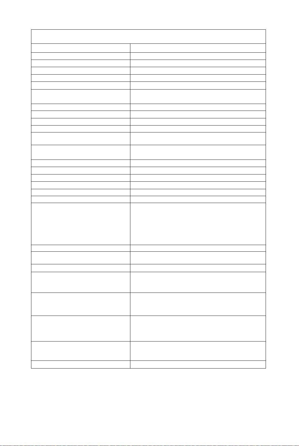
Installation
^Connecting Procedures
Turn off your computer.
Connect the signal connectors as shown below.
Turn the monitor on, then turn on the computer.
A. IBM PS/2 or compatible models
Rear view
monitor's port.
CD Connect the other end of this cable to
a power outlet.
B. Apple computer
© Use a UNIMAC-82D MAC adapter.
Panasonic MAC adapter
If you need an adapter and one is not provided
by your dealer, call 1 -800 PANASYS (1 -800726-2797).
r—Caution:-----------------------------------
To prevent the cable from coming loose,
the cable connectors must be securely
fastened with screws.
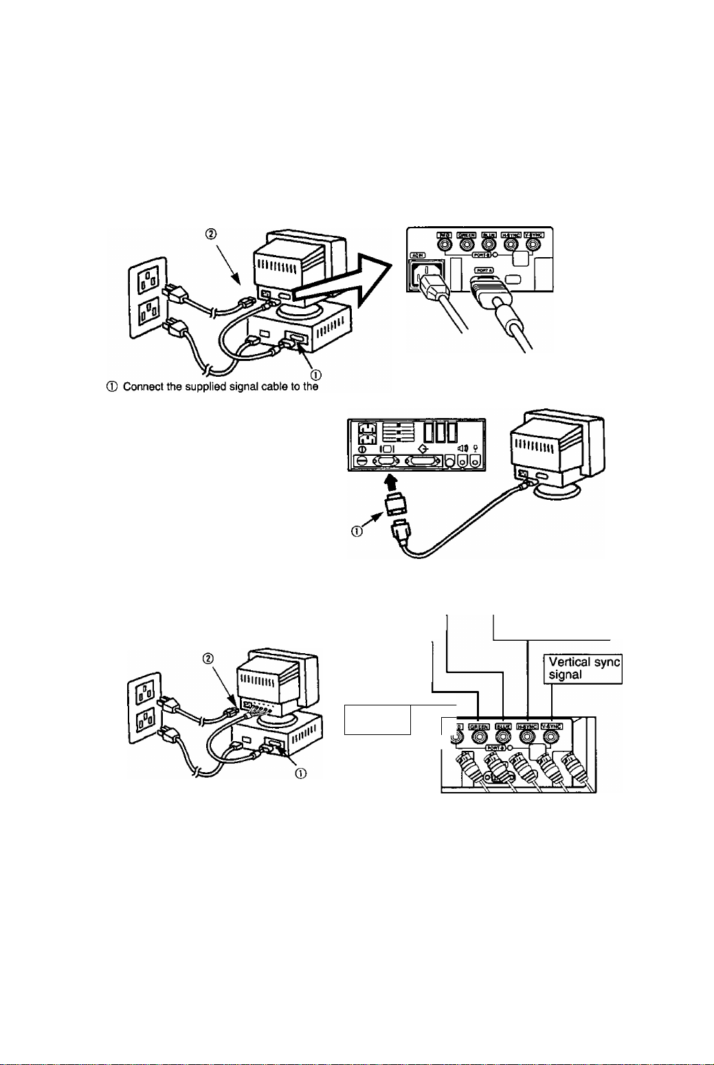
C. BNC connector signal computer
Rear view
AC power cord
Blue video signal
Green video
signal or sync
on green
Red video
—
signal
15-pin mini
D-Sub cable
Horizontal sync
signal or composite
sync signal
© Connect the BNC singnat cable (Not supplied) to the monitor's port.
@ Connect the other end of this cable to a power outlet.
^Connection of AC Power Suppiy
If the AC power supply voltage is in the range 100 to 240V, either 50Hz or 60Hz frequency can be
used.
There is no AC100V/240V selector switch as selection is automatic.
Precaution:
• In order to use the display unit safely, use a power cable that is properly grounded.
• AC plug cords for the following countries are supplied in the same package.
U.S.A
.......
UL
^ For use in other countries, make sure the AC cord meets the safety standards of each country.
Canada ....CSA
— 5 —
Page 12
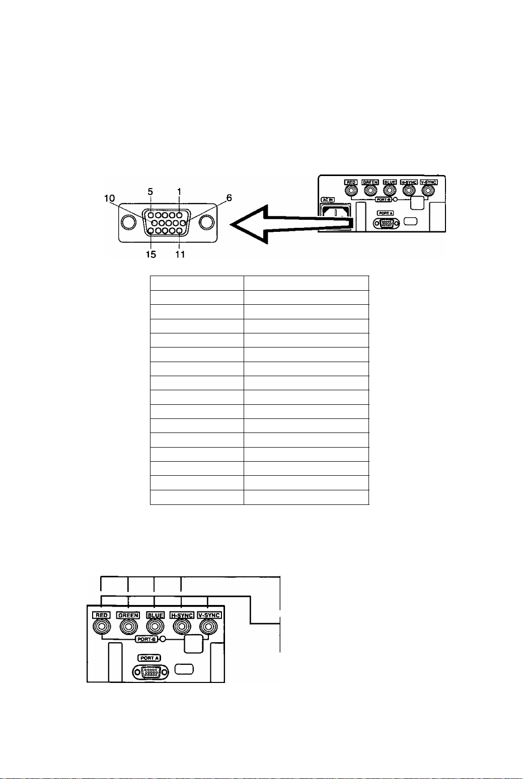
Pin Assignment
Follow the instructions below to connect the S110 to a computer.
A. Signal connector: 15-pin mini D-Sub (PS/2 or PC/AT compatible model)
Connect the signal cable to the 15-pin mini D-Sub connector on the display unit.
B. Signal connector: 15-pin D-Sub (Apple computer)
Convert a MAC 15-pin D-Sub connector to a 15-pin mini D-Sub connector using a Panasonic MAC adapter,
and connect it to the 15-pin mini D-Sub connector on the display unit.
<REAR PANEL >
Pin assignments of 15-pin mini D-Sub connector
Pin number
1
2
3
4
5
6
7 Ground for Green video signal
8
9 Unused
10
11
12 SDA* (Bi-directional Data)
13
14 Vertical sync, signal
15 SCL* (Data Clock)
★ : “VESA”s Display Data Channel (DDC) Standard.
Signal name
Red video signal
Green video signal
Blue video signal
Ground
Ground*
Ground for Red video signal
Ground for Blue video signal
Ground
Ground
Horizontal sync, signal
C.Signal connector: bnc connector
Sync on green system
Connect the signal cable to RED, GREEN (sync on
green) and BLUE BNC connectors.
Composite sync system
Connect the signal cable to RED, GREEN, BLUE
and H-SYNC (H/V oomposite)BNC connectors.
Separate sync system
Connect the signal cable to RED, GREEN, BLUE
and H-SYNC and V-SYNC BNC connectors.
Note : If your computer’s video output is over 110MHz, it Is recommended that it be
used with the BNC connectors.
-6 -
Page 13
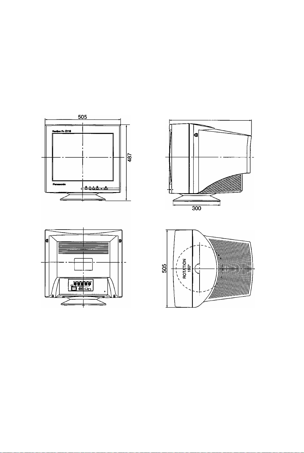
External View
Dimensions Pan/Tilt range
Width : 505mm (19.9“) Up
Height; 487mm (19.2") Down
Depth : 519mm (20.4") Left, right:
Base diameter: 300mm (11.8")
Height without stand : 441.5mm (17.4“)
13 degrees
4 degrees
90 degrees each
519
-7 -
Page 14
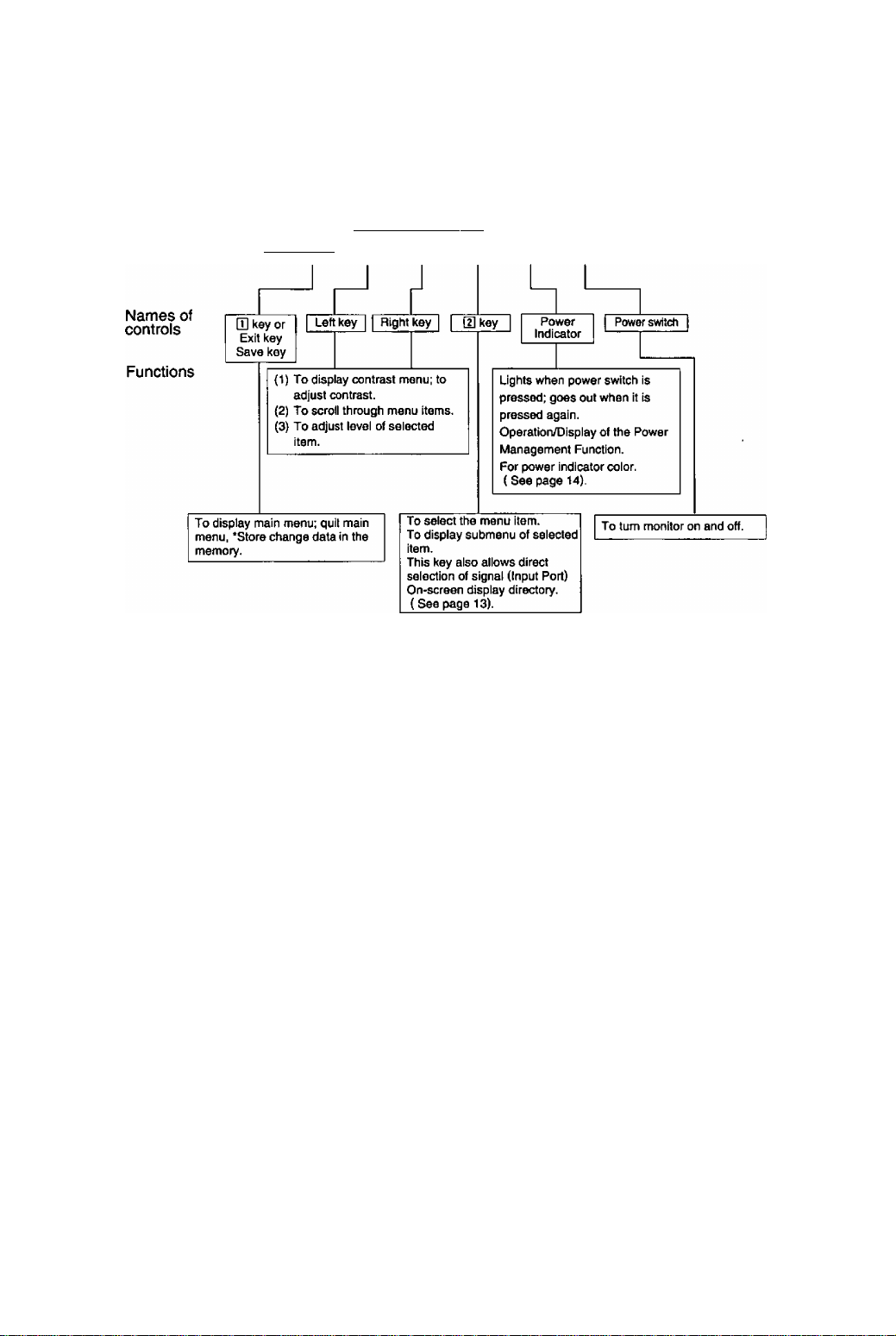
On-Screen Adjustment
[Basic operation]
B < > m
Control panel
• For a detailed description of the functions of the Q] key, left key, right key, and d]
key, refer to page 9-13.
* Since contrast is the most commonly adjusted parameter, we have provided direct
access to this menu item. By pressing the 3 or B key during normal operation the
Contrast adjustment menu is displayed instantly.
Q i —if— K
<E)
-8 -
Page 15
Operation
< Onscreen Display>
Monitor Self-Test
Figure A.
No Signal
fH —.—kHz
fV —Hz
Port ^ ■©■
Figure B.
Error
fH 98.0kHz
fV 80.0 Hz
Port 1^ -0-
Menu
The adjusted items are represented by
icons.
When the [T] key is pressed, the menu
screen appears.
Use the a • B keys to move the cursor
to the item to be adjusted, then press
the d] key to call the adjust menu.
Ю
о
Ш
о
a
aaa
OSD
aaa
я
Cent
rast
Э Contrast adjustment
Contrast
100
Э
^ Brightness adjustment
Brightness
50
Э :d]
< Function and Operation>
This display indicates that the monitor is
operating normally. When one of the following
conditions occurs, press one of the 4 front
panel keys to call the appropriate display.
1) No Signal (The computer is not connected or
the mains power to the computer is
disconnected). See figure A.
2) The horizontal or vertical sync, signal are
outside of the permitted range (the value of
the horizontal sync, signal will be displayed in
red and the value of the vertical sync, signal
will be displayed in white). See figure B.
cm
_i^_
a
a
Contrast
Brightness
Size & Роз.
H.Position
H.Size
V. Position
V.Size
Geometry
V.Pincushlon
Side Pin. Bal.
Trapezoid
Parallelogram
Rotation
Coior Temp
Recall
H, (Hoire
V. Moire
Language
OSD Position
Degauss
Signal
Э
a
о
(SI
о
íiO Video Level
?й
SIS
я
Adjust the screen contrast to match the
brightness level in the room. Press the B key to
make the image lighter, the a key to make it
darker.Pressing the [U key toggles between
brightness and contrast.
Direct operation: Even if the Menu screen does
not appear, the contrast can be adjusted by
pressing the 3 or B key.
If the a and B keys are pressed at the same
time on the Contrast adjustment screen, the
maximum level (100) will be set.
Contrast adjusts the white level.
Adjust the brightness to match the brightness
level in the room. Press the a key to make the
background darker, the B key to make it lighter.
Pressing the [U key toggles between brightness
and contrast.
Brightness adjusts the black level.
* If the a and B keys are pressed at the same
time on the Brightness adjustment screen, the
standard level (50) will be set.
-9 -
Page 16
< Onscreen Display >
< Function and Operation >
Size & Pos.
Press the d] key to select the Horizontal Position / Horizontal Size / Vertical Position /
Vertical Size adjustments.
ra Horizontal Position
adjustment
H. Position
50
os s m :[a
Horizontal Size
adjustment
1B3e S m
m Vertical Position
adjustment
V. Position
50
E3i S Q CE :d]
The horizontal position of the image can be
adjusted. Press the 3 key to move it to the left,
the B key to move it to the right.
(Center the image.)
* Press the \J} key to save the adjustment.
The horizontal size of the image can be adjusted.
Press the 3 key to make the image smaller, the
B key to make it larger. Then press the Q] key to
save the adjustment.
* Setting the image in the center of the screen will
make the size adjustment easier.
The vertical position of the image can be
adjusted. Press the 3 key to move it downward,
the B key to move it upward.
(Center the image.)
* Press the [H key to save the adjustment.
Vertical Size adjustment
CBi S Q IE :[2]
The vertical size of the image can be adjusted.
Press the 3 key to make the image smaller, the
B key to make it larger. Then press the U] key to
save the adjustment.
* Setting the image in the center of the screen
will make the size adjustment easier.
FI Geometry
Press the H] key to select the Vertical Pincushion / Side Pincushion Balance / Trapezoid /
Parallelogram adjustments.
o Vertical Pincushion adjustment
V. Pincushion
The image can be corrected for barrel distortion.
Press the 3 key to decrease the barrel distortion
of the image, the B key to increase it.
50
Oan^ :[2
-10 -
Page 17

< Onscreen Display>
< Function and Operation>
Q Side Pincushion Balance
Side Pin. Bal.
50
na :[u
O Trapezoid adjustment
T ra p e zo i d
50
UCLCXO
[J Parallelogram adjustment
Parallelogram
50
n a QZ7 :[2]
tQ Rotation (Image tilt)
adjustment
Rotation
50
The image can be corrected for barrel balance
distortion. Press the 3 key to expand to the left of
the image, the B key to expand to the right it.
The image can be corrected for trapezoidal
distortion.
Press the 3 key to make the top edge narrower,
the B key to make the bottom edge narrower.
The image can be corrected for parallelogram
distortion.
Press the 3 key to collapse the parallelogram to
the left, the B key to collapse it to the right.
Use this to adjust for tilt on the screen.
Press the 3 key to rotate the image slightly
counterclockwise, the B key to rotate the image
slightly clockwise.
‘Pressing the 3 and B keys simultaneously adjusts
rotation to its factory preset level (50).
Color Temp
Color Temp
H 2 3 4 5
9300K+8
User Color adjustment
Note: Record the initial values of R, G and B
here before making any adjustments:
R ( Red)
G ( Green )
B { Blue )
__________________
__________________
__________________
-11-
The white in the image can be adjusted.
1) Use the 3 • B keys to select 1: 9300 K + 8
MPCD, 2: 7500 K, 3: 6500 K, 4: 5000 K or 5 :
the user's preferred color.
2) If ” 5 : user's color" is selected, “ [U" appears
in the lower right of the On-Screen Display.
Press the front H] key to call the User Color
adjustment screen.
The white in the video image can be adjusted to
the user’s preferred color.
1) Use the key to select R (red) or G (green)
or B (blue).
2) Use the 3 • B keys to adjust the color as
desired.
‘ Recall of the user’s color Is not possible,
so make a note of the initial setting before
adjusting.
Page 18

< Onscreen Display>
< Function and Operation>
^ Recall
Recall
OK ?
[H: Yes
No : S
¿1© Video Level
Video Level
0.7 V
0.7/1 V :(S]
^ H. Moire reduction
H. Moire
Off
On/Off : [2]
To return to the initial settings (the settings at the
time of factory shipment).
1) When the lU key (Yes) is pressed, the settings
are recalled and the menu screen returns.
(Recall = return to settings at time of factory
shipment.)
2) When the \2} key (No) is pressed, the menu
screen returns without the settings being
recalled (the settings return to what they were
immediately before the recall).
• If no operations are performed for about 30
seconds, the screen goes off without recall.
The video input signal level can be matched to
the computer being used. Either 0.7V or 1 .OV
can be selected with the H\ key.
Note : 0.7V is typical.
(If wrong level is selected image may be too dim
or too bright.)
Horizontal moire reduction turned On or Off.
Use the H] key to select On or Off.
H. Moire adjustment
H. Moire
50
On/Off :
V. Moire reduction
V. Moire
Off
On/Off : {2\
V. Moire adjustment
V. Moiré
50
On/Off :
When On is selected with [H key, the adjustment
screen appears.
Adjust the horizontal moire to its optimum
condition using the 9 and B keys.
Press Q] to return to main menu and save
adjustment.
Vertical moire reduction turned On or Off.
Use the [H key to select On or Off.
When On is selected with [H key, the adjustment
screen appears.
Adjust the vertical moire to its optimum
condition using the 9 and B keys.
Press Q] to return to main menu and save
adjustment.
-12 -
Page 19

< Onscreen Display>
< Function and Operation>
Language selection
Language
DEU FRA lagia
ITA ESP
gig OSD Position
« t
I I**! I*»! I
^ Degauss
Degaussing operation can be selected.
After this is selected, the degaussing action takes place for approximately 6 seconds.
Key operation is not possible while demagnetization is performed.
The language used by the On-Screen Display
can be selected with the "3" and "B" keys from
among German, French, English, Italian and
Spanish.
DEU: German
FRA: French
ENG: English
ITA : Italian
ESP: Spanish
It is possible to adjust the position that the on
screen Menu is to be displayed.
The Menu will rotate in a counter-clockwise
direction every time the [H key is pressed.
o Signal (Input Port)
1280 X 1024
fH 63.7kHz
fV 60.1 Hz
Port
This displays the input synchronization signal
frequency.
Information on the input screen mode {resolution,
horizontal and vertical synchronization frequency)
wilt be displayed on the display monitor. There
are occasions sometimes when some screen
modes in use do not display any resolution. Direct
operations allow this to be displayed on screen by
pressing the H] key even when the menu screen
is not displayed.
Use the 3 or B key to select either the rear
panel input terminal port A (Mini D-Sub type) or
port B {BNC type).
Csution: When power management Is in effect
on either port A or port B, the input cannot be
switched from one to the other.
Release the power management before switching
the terminal selection. See page 14.
“How to release the system from the Power
Management Function,’’
-13 -
Page 20
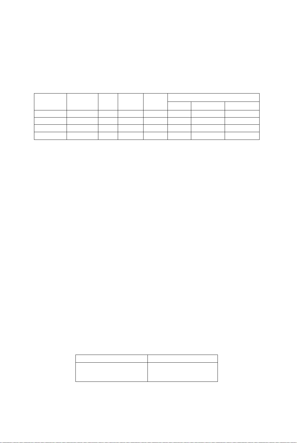
Power Management System
This monitor conforms to the VESA DPMS standard.
This function can reduce power consumption by the dispiay unit.
The computer and video board being used must aiso conform to the VESA DPMS
standard.
* Consuit the Operation Manuals for the hardware being used.
Modes change in response to input signals as indicated in the table below.
APM State
ON STATE
STAND-BY without display
SUSPEND
OFF STATE without display yellow < 4 watts < 20 sec. OFF OFF OFF
Screen status
with display green normal — ON ON ON
without display
Power
Indicator
color
yellow
yellow
Power
consumption
< 15 watts < 4 sec.
<15 watts
Return time
< 4 sec. OFF ON OFF
video horizontal sync. vertical sync.
OFF
Caution
How to release the system from the power management function.
1) Read the Operation Manuals for the hardware you are using.
2) Press one of the U] • a • B • d] keys on the front panel.
The No Signal screen appears, and the monitor side power management function is
released (only in OFF STATE).
Input signals
OFF ON
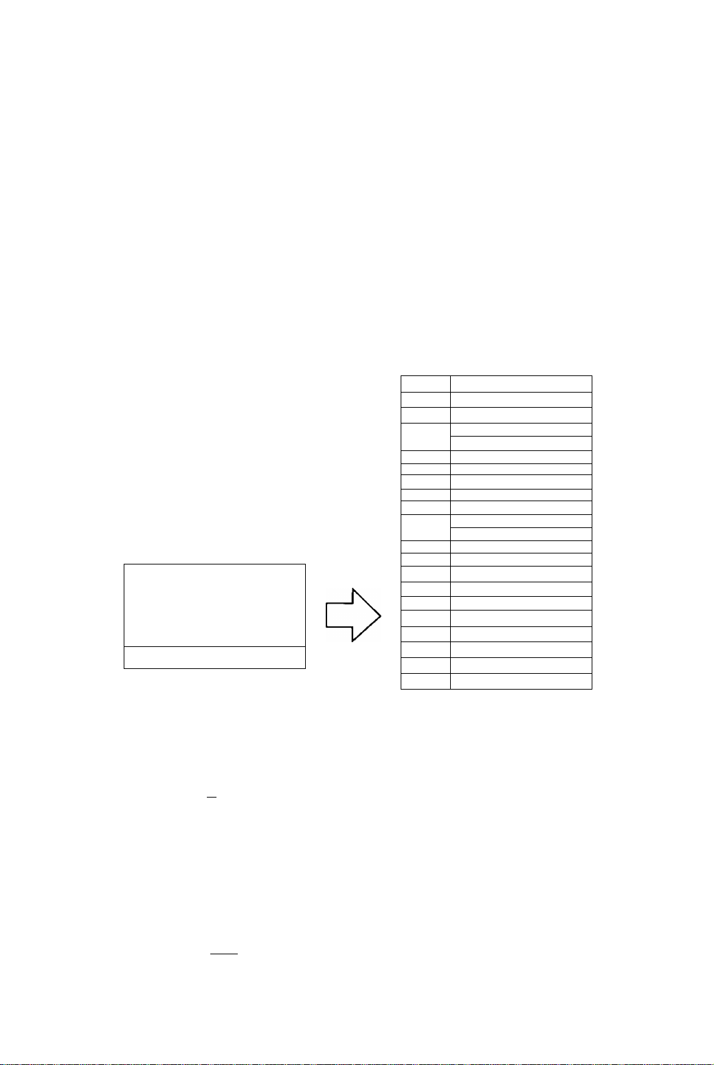
Memories
This display has two types of memory to store the data sets that control the on-screen
image. The first type of memory is the Preset Memory which is set by the factory. The
second type is the User Memory which is set by the user. Both memories store the
Horizontal Size, Vertical Size, Horizontal Position, Vertical Position, Vertical Pincusion,
Side Pincushion Balance, Trapezoid and Parallelogram adjustments of the displayed
image.
Preset Memory
There are 1 preset (7 reservation) timings that are set by the factory. The preset timing will automatically size
and center the image with video boards which use these timings. Please see page 15 for Timing Specifications.
User Memory
• There are 13 memory locations that allow for user timing. The image size, position, geometric distortion are
adjusted by the user. Please see page 16 and 17 for recommended timings that the display supports.
• If the User Memory is completely full, and a new set of data is saved, the oldest data set in the User Memory
will be deleted.
• The User Memory has priority over the Preset Memory.
• When the user timing is input, the Vertical, Horizontal frequencies and sync polarities of the signal are
compared with the previous data stored in memory. The input signal will be stored as a new data set if one
of its parameters is different from the previous stored one.
• The new input signal must have a frequency difference greater than that shown in the table below or a
different sync, polarity from that already stored. If the new timing data includes frequency changes greater
than those shown in the table below or sync, polarity changes, a new user memory setting will be stored. If
the frequency difference is smaller than that of the chart and the sync, polarities are the same, the existing
settings will be retained.
Horizontal frequency Vertical frequency
Low 30 kHz ± 0.4 kHz
to
Hi 95 kHz ±1.0 kHz
Please note If the timing does not meet the display specifications, the size and position adjustment may not
appear as desired. Be sure the horizontal and vertical timing are within the monitor specification range.
See page 15 for Timing Specifications. And pages 16 and 17 for preset, reservation and recommended timing.
Low 50 Hz ± 0.6 Hz
to
Hi 180 Hz ±1.8 Hz
-14
Page 21

Timing Specifications
Separate Sync.
Horizontal
Vertical
H/V Composite Sync.
Horizontal
Vertical
—LT
uB4
“LT
“LT
innnnn nnnnr-
.8
Video
Video
s !—r
4^
4^1
U
IT
Video
s
U
Innrt
Sync, on Green
Horizontal
D
Vertical
-15 -
Page 22
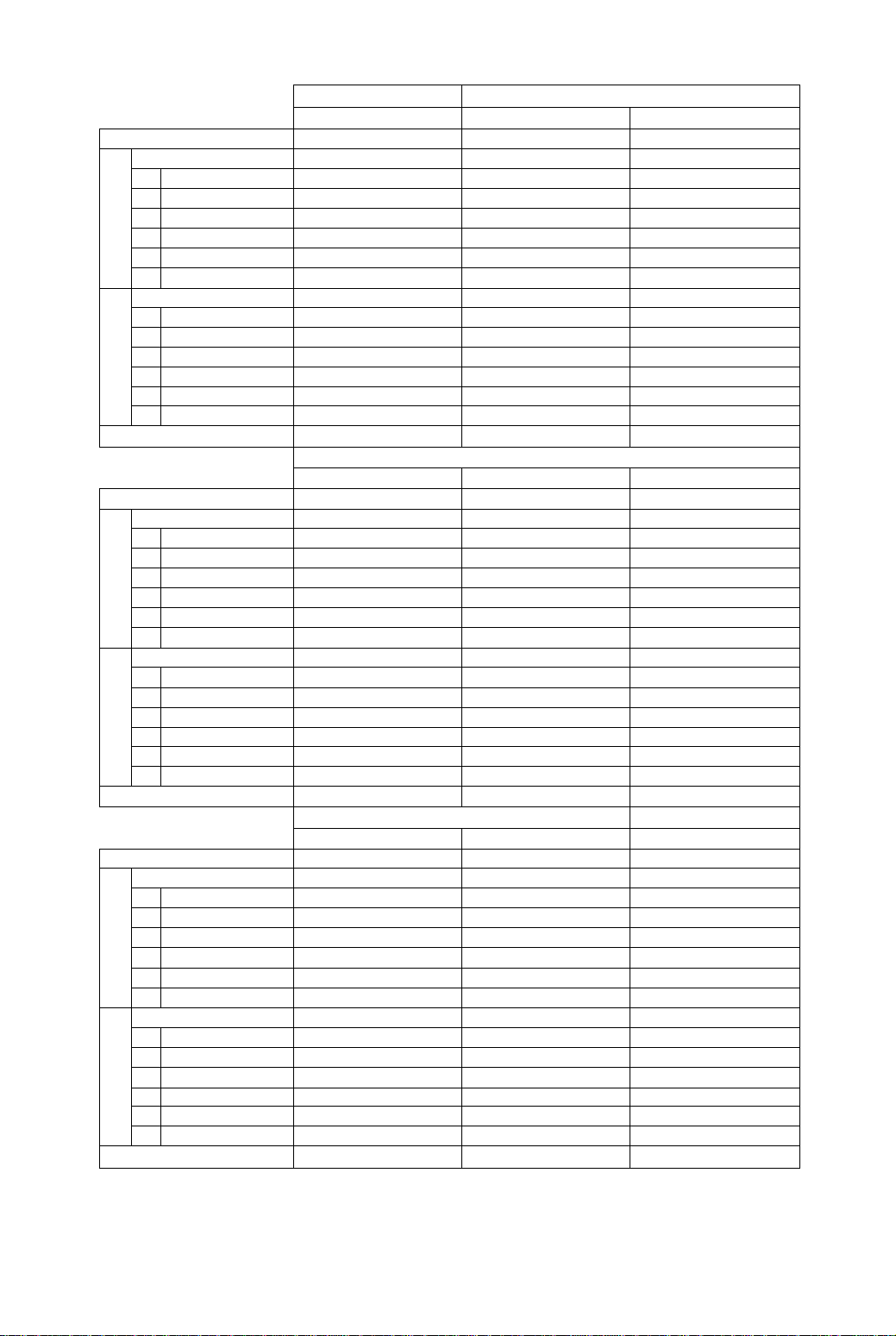
Preset timing*
VESA/UXGA1600x1200 e75Hz
Dot clock
fH
A H-Period
CQ
F H-Blanking
C
О
В
N
О
X
H-Sync width
H-Back porch
c
D H-Active
E H-Front porch
fV
P
V-Period
U V-Blanking
Ü
tr
>
V-Sync width
Q
R
V-Back porch
S
V-Active
T
V-Front porch
Sync polarity (H/V)
202.500 MHz
93.750 kHz
10.667 us (2160dots)
2.765 us ( 560dots)
0.948 us ( 192dots)
1.501 us ( 304dots)
7.901 usdeOOdots)
0.316 us( 64dots)
75.000 Hz
13.333 ms(l 2501ines)
0.533 ms ( SOlines)
0.032 ms ( 3lines)
0.491 ms ( 46lines)
12.800 ms(l200lines)
0.011 ms( nine)
Positive/Positive
VESA 1024x768 @75 Hz
Dot clock
fH
_
A
H-Period
F
C
о
N
О
X
H-Blanking
В
H-Sync width
C
H-Back porch
D
H-Active 13.003 us (1024 dots)
E
H-Front porch
fV
P
V-Period 13.328 ms (800 lines)
"5
U V-Blanking
Q
c
>
V-Sync width
R
V-Back porch
S V-Active
T
V-Front porch
Sync polarity (H/V)
78.7500 MHz
60.023 kHz
16.660 us (1312 dots)
3.657 us ( 288 dots)
1.219 us ( 96 dots)
2.235 us (176 dots)
0.203 us( 16 dots)
75.029 Hz
0.533 ms ( 32 lines)
0.050 ms ( 3 lines)
0.466 ms ( 28 lines)
12.795 ms (768 lines)
0.017 ms ( 1 line)
Positive/Positive
~ 12.667 ms( 870lines)
Reservation timing**
VESA 1280x1024 @75 Hz
_
C
о
N
О c
co
tr
ф
>
Dot clock
fH
A
H-Period 12.504 us (1688dots) 11.429 us (2160dots)
F
H-Blanking
В
H-Sync width 1.067 us ( 144dots)
H-Back porch
D
H-Active
E
H-Front porch
fV
P
V-Period
U
V-Blanking
Q
V-Sync width
R
V-Back porch
S
V-Active 12.804 ms(1024lines) 13.714 ms (1200lines)
T
V-Front porch
135.0000 MHz
79.976 kHz 87.500 kHz 37.861 kHz
3.022 us ( 408dots)
1.837 us ( 248dots)
9.481 us (1280dots)
0.119 us ( 16dots)
75.025 Hz
13.329 ms(1066lines)
” 14.286 ms (1250lines) 11.886 ms ( 450lines)
0.525 ms ( 42linesi
0.038 ms ( 3lines)
0.475 ms ( 38lines)
0.013 ms ( nine) 0.011 ms ( nine)
Sync polarity (H/V) Positive/Positive
NoteiAII modes are Non-Interlaced.
* Factory Presets have exact size & centering.
** Factory Reservations have approximate size & centering.
*** Requires the use of Optional Mac Adapter UN1MAC-82D.
-16 -
Reservation timing**
VGA 640 X 480 @ 60 Hz
25.1750 MHz
31.469 kHz
31.778 us ( 800 dots)
VESA 800x600 @ 75 Hz
49.5000 MHz
46.875 kHz
21.333 us (1056dots)
6.356 us (160 dots) 5.172 us ( 256dots)
3.813 us ( 96 dots) 1.616 us ( 80dots)
1.907 us ( 48 dots) 3.232 us ( 160dots)
25.422 us ( 640 dots) 16.162 us ( SOOdots)
0.636 us ( 16 dots) 0.323 us ( 16dots)
59.940 Hz
16.683 ms (525 lines)
1.430 ms ( 45 lines)
0.064 ms ( 2 lines)
1.049 ms ( 33 lines)
15.253 ms (480 lines)
75.000 Hz
13.333 ms (625lines)
0.533 ms ( 25lines)
0.064 ms ( 3lines)
0.448 ms ( 21lines)
12.800 ms (eOOlines)
0.318 ms (10 lines) 0.021 ms ( nine)
Negative/Negative
Positive/Positive
Resen/ation timing**
MAC 1152 x 870 ©75 Hz***
100.0000 MHz
68.681 kHz
14.560 us (1456dots)
3.040 us ( 304dots)
1.280 US ( 128dots)
1.440 us ( 144dots)
11.520 us (1152dots)
0.320 us ( 32dots)
75.061 Hz
13.322 ms ( 915lines)
0.655 ms ( 45lines)
0.044 ms ( 3lines)
0.568 ms ( 39lines)
VESA 1280x1024 @60 Hz
108.5000 MHz
63.974 kHz
15.631 us(l696dots)
3.834 us ( 416dots)
1.180 us ( 128dots)
2.065 us ( 224dots)
11.797 us(1280dots)
0.590 us ( 64dots)
60.013 Hz
16.663 ms(1066lines)
0.657 ms ( 42lines)
0.047 ms ( 3lines)
0.594 ms ( 38lines)
16.006 ms(1024lines)
0.044 ms ( 3lines)
Negative/Negative
0.016 ms ( 1line)
Positive/Positive
Recommended timing
VESA 1600x1200 @70 Hz640 X 350 @ 84 Hz
189.0000 MHz 31.5000 MHz
26.413 us ( 832dots)
2.963 us ( 560dots)
1.016us( 192dots)
1.608 us ( 304dots)
6.095 us ( 192dots)
1.270 us ( 40dots)
4.063 us ( 128dots)
8.466 us (1600dots) 20.317 us ( '64Òdots)
0.339 us ( 64dots) 0.762 us ( 24dots)
70.000 Hz
0.571 ms ( SOlines)
0.034 ms ( 31ines)
0.526 ms ( 46lines)
84.135 Hz
2.641 ms ( lOOlines)
0.079 ms ( 31ines)
1.638 ms ( 62lines)
9.244 ms ( 350lines)
0.924 ms ( 35lines)
Positive/Positive
Positi ve/Negative
Page 23

Recommended timing
640 X 400 @ 85 Hz
Dot clock
31.500 MHz
fH 37.860 kHz
A
rt
c
o
_N B
o
H-Period
F H-BIanking
H-Sync width
c H-Back porch
D H-Active
26.413 us ( 832dots)
6.095 us( 192dots)
2.032 us { 64dots)
3.048 us( 96dots)
20.317 us ( 640dots)
E H-Front porch 1.016 us ( 32dots)
fV
P V-Period
CO
u
c Q
>
V-Blanking
U
V-Sync width
R V-Back porch
85.080 Hz
11.754 ms(445lines)
1.189 ms ( 45lines)
0.079 ms { 3lines)
1.083 ms ( 41 lines)
S V-Active 10.565 ms(4001ines)
T
V-Front porch 0.026 ms( nine)
Sync polarity (HA^) Negative/Positive Negative/Negative
800 X 600 @ 85 Hz
Dot clock
fH
56.2500 MHz
53.674 kHz
A H-Period 18.631 us(1048dots)
F H-Blanking 4.409 us { 248dots)
c
o
B H-Sync width 1.138 us ( 64dots)
N
O
C H-Back porch
D H-Active
E H-Front porch
fV
P V-Period
>
CQ
Ü
V-Blanking
U
V-Sync width
Q
R V-Back porch
S V-Active
T V-Front porch
Sync polarity (HA/)
2.702 us ( 152dots) 2.201 us( 208dots)
14.222 us ( eOOdots) 10.836 us(1024dots)
0.569 us( 32dots)
85.060 Hz
11.756 ms(631lines)
0.578 ms ( 31 lines)
0.056 ms ( 3lines) 0.044 ms( 3iines)
0.503 ms ( 27lines)
11.179 ms (600lines)
0.019 ms( nine)
Positive/Positive Positive/Positive
640 X 480 @ 85 Hz
36.0000 MHz
43.269 kHz
23.111 us Í 832dotsl
5.333 us Í 192dots)
1.556 us Í 56dots)
2.222 us ( 80dots)
17.778 us( 640dots)
1.556 us ( 56dots)
85.010 Hz
11.763 ms(509lines)
0.670 ms ( 29lines)
0.069 ms( 3iines)
0.578 ms ( 25iines)
11.093 ms(480lines)
0.023 ms( nine)
Recommended timing
1024x768 @ 85 Hz
94.5000 MHz
68.677 kHz
14.561 us(1376dots)
3.725 us( 352dots)
1.016 us( 96dots)
0.508 us ( 48dots)
85.000 Hz
11.765 ms(808lines)
0.582 ms( 40iines)
0.524 ms ( 36lines)
11.183 ms (768lines)
0.015 ms ( nine)
720 X 400 © 85 Hz
35.5000 MHz
37.928 kHz
26.366 us ( 936dots)
6.085 us( 216dots)
2.028 us( 72dots)
3.042 us ( lOSdots)
20.282 us ( 720dots)
1.014 us ( 36dots)
85.040 Hz
11.759 ms (446lines)
1.213 ms ( 46iines)
0.079 ms( 3lines)
1.107 ms ( 42lines)
10.546 ms( 400lines)
0.026 ms( nine)
Negative/Positive
1152x900 © 66 Hz
92.9407 MHz
61.797 kHz
16.182 us(1504dots)
3.787 us ( 352dots)
1:377 us ( 128dots)
2.098 us ( 195dots)
12.395 us(1152dots)
0.312 us{ 29dots)
65.950 Hz
15.163ms( 937lines)
0.599 ms ( 37lines)
0.065 ms{ 4lines)
0.502 ms ( 31lines)
14.564 ms (900lines)
0.032 ms ( 2lines)
Composite
Recommended timing
1280x1024 0 85 Hz 1600x1280 0 71 Hz*
Dot clock 159.380 MHz
fH 91.374 kHz
A
(0
c
o
N
o
X
H-Period
F H-Blanking
B H-Sync width 0.853 us ( 136dots)
H-Back porch
C
D H-Active 8.032 us(1280dots)
E H-Front porch
fV
P V-Period
15
Ü
■■E
o
>
V-Blanking
U
V-Sync width
Q
R V-Back porch
S V-Active
T V-Front porch
Sync polarity (H/V)
10.944 us(1744d0ts)
2.912 us( 464dots)
1.456 us ( 232dots)
0.602 us ( 96dots)
85.00 Hz 71.00 Hz
11.765 ms(1075lines) 14.084 ms (13331ines)
0.558 ms( 51 lines)
0.033 ms{ 3lines)
0.514 ms ( 47lines)
11.207 ms (1024lines)
0.011 ms( nines)
Positive/Positive Positive/Positive
207.4570 MHz
94.643 kHz
10.566 us{2192dots)
2.854 us( 592dots)
0.848 us ( 176dots)
1.427 us ( 296dots)
7.712 us (1600dots)
0.578 us ( 120dots)
0.560 ms{ 53iines)
0.032 ms{ 3iines)
0.518 ms( 49lines)
13.524 ms(1280lines)
0.011 ms( nines)
* Note : 1600 X 1280 @ 71 Hz mode meets FCC class A in U.S.A. but does not meet the European
standard EN55022 class B for CE marking.
—17 —
Page 24

If trouble occurs with the display unit, perform the following checks and take the indicated action; if the trouble persists, please consult with your dealer.
Symptom
Thera is no display
on
The image is too large or too
small, or it is displaced from
the correct position.
□ □
The display color is abnormal.
(Example) The color is
uneven or off-color.
The image distortion and or
tilt is large.
im [HI
The background of the image
is bright.
The background of the image
is colored.
The character gets partially
distorted.
The image is dark.
1 iHi 1 LJ
Characters cannot be seen
clearly; the image is too dark.
The screen size and position
do not change.
The front panel keys fail to
operate.
Check
power cord/plug
power switch
signal cable
The power saving function might
have acted (if so the pilot LED
will be yellow).
The mode is not registered.
Is there something that produces
a magnetic field nearby?
(Examples) Television monitor,
another computer display unit,
speaker, etc.; was the
orientation of the monitor
perhaps changed while it was in
use?
The computer in use is Macintosh.
The signal output of the computer
in use is improper.
Is the image signal level correctly
adjusted?
Is the brightness or contrast
adjustment turned all the way
down?
Is the input synchronization signal
within the operating range?
Are 2 or more Keys being
operated at the same time?
Action
Plug the power cord into the outlet correctly.
Press the power switch.
Connect the signal cable correctly.
Release the power saving function by operating
the mouse or keyboard.
For additional details please read the Operation
Manual of the hardware you are using.
Perform the desired settings and then save them
by waiting 20 seconds or pressing the Q] “Exif key.
Remove the source of the magnetic field.
Perform degaussing.
Make sure your cable is correct.
Connect the signal connector correctly.
Try a different orientation.
Press the operating keys Q] and [3 together at
the same time. You can then adjust this unit with
the signal output of the computer. One more
pressing or execution of recall can cancel this
function.
*This function is effective for a specified
computer. If there is no problem in normal use,
avoid the use of this function.
Check the video signal level from the computer
and adjust it in the correct direction.
Adjust the brightness and contrast.
Check the video output mode from the computer,
and select a mode within the display unit operating
range.
For details, please read the Operation Manual of
the hardware you are using.
Operate only one key at a time.
-18 -
Page 25

Technical Support (USA Only)
If you have read the Operating Instructions
and tried the troubleshooting procedures and
are still having difficulty, please contact the
dealer from whom the unit was purchased.
You may also call the end user Technical
Support telephone number which is
operational twenty four (24) hours a day
seven days a week.
AllowableiH-hV) Frequency Range
Apple (Apple Computer)
......................
.......
Brightness............................................9
Color Temp........................................11
Contrast
...............................................
CSA......................................................5
Danger.................................................1
DDC
.....................................................
Degauss.............................................13
Dimensions
..........................................
DPMS...................................................3
Energy Star®....................................iv
Geometry
Horizontal Frequency Range
...........................................
...............
Horizontal Moire.................................12
Horizontal Position.............................10
Horizontal Size...................................10
IBM (or Compatible)
Language selection
............................
...........................
Menu....................................................9
Monitor Self-Test
MAC(Macintosh)
On-Screen Adjustment
................................
..................................
.......................
To contact the Technical Support Group call:
1-800-726-2797 (24 Hours a day)
To locate the Nearest Authorized Panasonic Service
Center call:
1-800-726-2797 (24 Hours a day )
To obtain Operating Instructions and Service Manuals
call:
1 -206-395-7343 (6:00 AM to 4:30 PM Pacific Time )
To locate the Nearest Sales Dealer call:
1-800-742-8086 (24 Hours a day )
To get the latest Windows 95 Panasonic Monitor.
INF Files call:
PanaTech BBS (201) 863-7845 (24 Hours a day)
You may also wish to see our world wide web pages at:
http://www.panasonic.com/alive
Index
4
OSD Position......................................13
10
13
5
Parallelogram
Pedestal Adjustment angle
Pin assignment.....................................6
9
Power Management System
Recall
.................................................
Rotation
3
Side Pincushion Balance
Signal (Input Port)
4
Size & Pos..........................................10
Specifications
Table of Contents
Trapezoid...........................................11
4
Trouble shooting.................................18
UL.........................................................5
User color Adjustment
Vertical Frequency Range
5
Vertical Moire
Vertical Position
Vertical Size
9
5
8
Video Level.........................................12
Vertical Pincushion.............................10
Warnings..............................................1
....................................
...................
...............
.............................................
...................
..............................
.......................................
................................
.......................
...................
.....................................
.................................
.......................................
11
4
14
12
11
11
13
4
1
11
4
12
10
10
-19 -
Page 26

Notice for Germany
NOTE:
• For ergonomic reasons, we recommend not to use the basic color blue on a dark background (bad recognition,
eye load with to small character contrast would be the result).
Attention:
• For sate operation of the monitor in the Federal Republic of Germany, it is required to use a plug-in device
connection cable with the VDE mark !
Notice for Japan
This equipment falls under the class B Information Technology Equipment based on the
standard established by the Self-imposed Control Council for Radio Interference through
Information-processing Equipment (VCCI). This equipment is designed to be used in a
household environment, However, if it is used near radio and television receiver units, radio
disturbances can occur. Use this equipment appropriately according to the instruction
manual.
Notice for Germany
HINWEIS
• Aus ergonomischen Gründen wird empfohlen, die Grundfarbe Blau nicht auf dunklem Untergrund zu
venwenden (schlechte Erkennbarkeut, Augenbelastung bei zu geringem Zeichenkontrast wäre die Folge).
Achtung:
• Für den sicheren Betrieb des Monitors in der Bundesrepublik Deutschland Ist es erforderlich, eine steckbare
Geräteanschlußleitung mit VDE-Zeichen zu verwenden!
Notice for Japan
zornmt. (vcci) <
'7 =70 iroiSBii- iett uTi,'
BS i ?l -r i t ff'S. u STo
ffifilÄTOlcSi o TiE L. 'IX U ffit' S U TT
-20 -
Page 27

Page 28

Conditions imposées par ia commission fédéraie des communications
L’appareil a été testé et jugé conforme aux limites des appareils numériques de classe B, aux termes de
la section 15 de la Réglementation FCC. Ces limites ont pour but d’assurer une protection raisonnable
contre les interférences parasites dans une installation résidentielle. Cet appareil engendre, utilise et peut
émettre une énergie radioélectrique et, s'il n’est pas installé et utilisé en stricte conformité avec ces
instructions, il peut provoquer des interférences parasites dans les liaisons radiophoniques. Ceci ne
garantit pas pour autant qu'une installation particulière n’émettra aucune interférence. Si l’appareil
engendre des interférences parasites avec la réception radio ou télévision, ce qui pourra être déterminé et
Conformité CE
Cet appareil est conforme aux exigences de la directive CEE 89/336/CEE modifiée par la directive
C€
Article exigé
Interférence électromagnétique #1
Décharge électrostatique #2 #3
Emission de radiofréquence
Salve rapide transitoire #1
Harmoniques de ligne #1
#1 : Satisfait aux normes sans problèmes de performance ni de fiabilité.
#2 ; Des effets peuvent apparaître temporairement sur l’écran, mais il n’y aura pas de problème de fiabilité.
#3 : Risque de panne.
#4 : Si l’on utilise un câble de signal autre que celui spécifié, il pourra provoquer une interruption d’onde
Manipuler conformément aux instructions.
EMI : Perturbation électromagnétique ESD : Décharge électrostatique
RF : Radiofréquence F/B: Salve rapide
92/31/CEE et par l’article 5 de la directive 93/68/CEE relative à la ‘'compatibilité électronique”, et de
la directive 73/23/CEE modifiée par l'articie 13 de la directive 93/68/CEE relative à la “sécurité”.
Par rapport aux valeurs standard
#1
électromagnétique dans les périphériques.
Pour garantir une conformité CE continue, l'utilisateur devra utiliser le câble fourni, à savoir le câble de
signal vidéo blindé de 1,5 m avec âmes de ferrite assemblées aux deux extrémités du câble.
Par rapport à ceux dépassant tes valeurs standard
------
—
#3
#3
Remarques
#4
w
4/
/N.
/
_____
\
En sa qualité de partenaire d’ENERGv Star®, Panasonic Computer Peripheral Company a
jugé que ce produit respecte les directive de rendement énergétique d’ENERGV Star*.
-22 -
Page 29

I Danger
Pour éviter tout risque d’éiectrocution grave y compris de mort, ne pas retirer les
couvercles (ni le dos) du moniteur. L’appareil ne renferme aucune pièce qui soit
réparable par l’utilisateur. Confier toute réparation à un personnel qualifié.
IAvertissements
Pour éviter tout risque de choc électrique et de feu :
Ne jamais rien poser sur le moniteur, le cordon d’alimentation secteur, veiller à ne
pas trop plier les cordons, et ne rien faire qui puisse affecter l’intégrité des cordons.
Toujours débrancher le cordon d’alimentation secteur de la prise en tirant sur la
prise et non sur le cordon proprement dit.
Ne pas poser de récipient renfermant des liquides (même un chiffon humecté de
liquide) sur le moniteur car la pénétration de liquides pourrait être source de danger
électrique. Ne pas exposer le moniteur ni l’adaptateur secteur à la pluie ou à
l’humidité.
Ne pas installer le moniteur sans respecter le jeu spécifié (voir les précautions, 1
Installation, Page 24). Ne pas boucher les orifices de ventilation. Ne pas insérer
d’objets dans les orifices de ventilation.
Renseignements à relever par le client
En cas de vol ou de perte, il est important de conserver le No. de série dans un dossier afin de
permettre l’identification. Noter le numéro de série dans l’espace prévu et conserver ce manuel à
titre de consignation permanente de l’achat. Il aidera à identifier l’appareil en cas de vol ou de perte.
Numéro de modèle: Si 10
Numéro de série i
______
Table des matières
Conditions imposées par la commission fédérale des communications
Conformité CE..............................................................................................22
Danger..........................................................................................................23
Avertissements.............................................................................................23
Renseignements à relever par le client
Table des matières.......................................................................................23
Mesures de précaution 1) Installation..........................................................24
Mesures de précaution 2) Utilisation
Mesures de précaution 3) Soin du produit...................................................24
Caractéristiques...........................................................................................25
Fiche technique............................................................................................26
Installation....................................................................................................27
Affectation des broches
Aspect extérieur...........................................................................................29
Réglage sur écran des paramètres
Réglage.......................................................................................................31
System de gestion d'énergie........................................................................36
Mémoires.....................................................................................................36
Spécifications de synchronisation................................................................37
En cas d'anomatie
Assistance technique...................................................................................41
Index............................................................................................................41
Notice pour l’allemagne
Notice pour le japon.....................................................................................42
...............................................................................
.......................................................................................
...............................................................................
.......................................................
...........................................................
.............................................................
.......
23
24
28
30
40
42
22
TOUS LES NOMS DE PRODUIT/MARQUE SOMT DES MARQUES DE FABRIQUE OU DES MARQUES DÉPOSÉES DES DÉTEMTEURS RESPECTIFS.
© 1997 MATSUSHITA ELECTRIC INDUSTRIAL Co.. Ltd.
-23 -
Page 30

Mesures de précaution
1) Installation
• Installer le moniteur dans un endroit suffisamment aéré. Eviter toute exposition en plein
soleil et à des sources de chaleur (appareil de chauffage, etc.). La chaleur aurait des
conséquences néfastes sur les coffret et sur les pièces internes.
• Placer l’écran de façon que les orifices du coffret ne soient pas obstrués pendant le
fonctionnement.
• Eloigner l’écran des cuisines, salles de bains, lave-linge et autres sources d’eau, de
vapeur et d’humidité.
• Pour utiliser l’écran en toute sécurité, utiliser exclusivement le cordon d’alimentation
fourni. Le cordon d’alimentation secteur devra être branché dans une prise secteur
correctement mise à la terre et polarisée. Le cordon d’alimentation secteur fourni
convient pour un usage aux Etats-Unis (UL) et au Canada (CSA), et on l’utilisera avec
l’adaptateur secteur fourni avec l’écran. Pour les autres pays, bien utiliser un cordon
qui respecte les normes de sécurité du pays en question.
• Placer le cordon d’alimentation dans un endroit où il ne subira pas de contrainte.
• Utiliser exclusivement les accessoires Panasonic fournis, ou des équivalents exacts.
2) Utilisation
• Ne pas tirer sur le cordon d’alimentation secteur, le cordon d’alimentation CC ni le
câble de signal VGA car cela pourrait endommager l’écran (te moniteur), faire tomber
l’appareil et provoquer des blessures.
• Anomalies de réception
S’il y a un téléviseur ou un autre écran à proximité, éloigner l’écran le plus possible. Les
interférences mutuelles pourraient provoquer une distorsion des Images ou des
parasites.
• Un contact prolongé avec des produits en caoutchouc ou en vinyle risque de tacher le
coffret.
• Lors du transport, protéger le moniteur contre les chocs. Faire attention au tube
cathodique.
• Ne rien poser sur le moniteur.
• Toujours faire attention au cordon d’alimentation.
Ne rien poser sur le cordon d’alimentation. Ne pas tenter de le rallonger, de le
raccourcir ni d’y faire des nœuds.
3) Soin du produit
• Avant de nettoyer le moniteur, débrancher le cordon d’alimentation secteur et le câble
de signal VGA du moniteur.
• Nettoyer l’extérieur du moniteur ou la surface de l’écran à l’aide d’un chiffon propre,
doux et sec. Si le moniteur ou la surface de l’écran sont très sales, humecter un
chiffon doux et propre de détergent neutre (par exemple un produit à vaisselle) et
d’eau, bien le tordre de façon qu’il soit presque sec, essuyer le moniteur ou la surface
de l’écran avec, puis les essuyer à nouveau avec un chiffon propre et sec. Ne pas
utiliser de solvants.
• Ne pas frotter ni heurter te moniteur avec quelque chose de dur ou de cassant car
cela pourrait le rayer, l’abîmer ou l’endommager irrémédiablement.
• Ne pas utiliser de chiffons chimiques ni de chiffons à cire car ils pourraient
endommager l’appareil et provoquer un enlèvement de la peinture.
-24 -
Page 31

Caractéristiques
1) Réglage numérique via l’affichage sur écran
• Le menu sur écran s’affiche en 5 langues au choix.
• On pourra sélectionner l'anglais, le français, l'allemand, I'italten ou l'espagnol.
• Le menu sur écran permet de personnaliser l’écran rapidement et en toute facilité à l’aide des quatre touches du
panneau avant.
• Le menu sur écran principal permet d’effectuer ces réglages en toute facilité en cliquant sur tes icônes pour
sélectionner un menu de réglage. La barre de sélection, qui se trouve au bas du menu principal, affiche le nom du
menu de réglage sélectionné.
• Les menus sur écran peuvent s’afficher à n'importe quel endroit de l’écran (six emplacements).
2) Le Plug & Play S110 est un moniteur compatible DDC 1/2B* qui utilise la norme VESA» (Video
Electronics Standards Association) DDC^“ (Display Data Channel). Ceci permet au S110 d’informer le serveur de
ses capacités qui respectent la définition Plug & Play de Microsoft»/lnteP utilisée par Windows* 95.
3) Gestion de l’alimentation
• Un circuit de gestion d'alimentation électrique conforme à la norme VESA DPMS est incorporé au moniteur vidéo.
Ceci permet de réduire la consommation du moniteur vidéo quand il est associé à une carte vidéo confomne à la
norme DPMS.
• Ce produit est conforme aux normes internationales du programme Energy Star*.
En sa qualité de partenaire d’ENERGY Star*, Panasonic Computer Peripheral Company a jugé que ce produit
respecte les directive de rendement énergétique d'ENERGY Star®.
4) Convivialité avec l’environnement
■ Tous les éléments en plastique sont identifiés par la désignation “recyclable".
5) Faibles émissions et prévention de charges statiques
• Le moniteur respecte les directives suédoises MPRII (SWEDAC) strictes de réduction des champs magnétiques
ELF et VLF et des champs électriques alternatifs.
• Le S110 respecte les normes de la Confédération suédoise des professionnels'TCO’92.
• Le revêtement anti-statique du tube cathodique réduit l’accumulation de charges électrostatiques. Cela évite les
décharges électriques en cas de contact avec l'écran et réduit l'accumulation de poussière.
6) Fonction de réglage de la couleur
• La balance du blanc de l’image peut être ajustée á volonté avec les réglages séparés des signaux du rouge (R),
du vert (V) et du bleu (B). Cette fonction permet de réaliser une mise en phase couleur appropriée.
• Il est possible de sélectionner la température de couleur de référence des blancs de 9300K + 8MPCD, 7500K,
6500K, 5000K ou une couleur utilisateur. Par exemple, les couleurs du moniteur vidéo peuvent être réglées afin
d’assurer une équivalence avec les couleurs qui sont représentées par la sortie sur imprimante couleur.
7) Multibalayage numérique PanaSync
• Une exploration automatique des fréquences horizontales comprises entre 30 kHz et 95 kHz et des fréquences
verticales comprises entre 50 et 180 Hz peur être commandée. Le moniteur est compatible avec tes cartes VGA,
SVGA, VESA et vidéo à haute résolution de1600 (H) x 1200 (V)/75 Hz.
• Huit (1 préréglées, 7 réservations) sélections de syncronisation sont prémémorisées en usine en termes de
dimensions d’image et de positionnement.
Il existe par ailleurs 13 autres sélections de synchronisation programmables à volonté par l’utilisateur.
8) Menu d’essai automatique
• Sans même avoir à brancher un ordinateur, le moniteur peut être vérifié en faisant apparaître le menu d'essai
automatique par l’intermédiaire des renseignements sur l’écran.
9) Canon à électrons DQ-DAF à circuit de compensation de focalisation hyperbolique
• Un canon à électrons DQ-DAF exclusif à circuit de compensation de focalisation hyperbolique capable de contrôler
les faisceaux électroniques est associé à un masque invar capable de faire apparaître des images de grande
précision sur toute la surface de l'écran plat et carré de 21 pouces (visionnement de 20,0 pouces/50,8 cm] et
espacement de points de 0,25 mm.
10) Autres caractéristiques
• La fonction de sélection automatique des signaux d’entrée de synchronisation (signaux séparés, composites ou
synchronisés au vert) a été prévue en qualité de fonction standard.
• Une embase orientable et inclinable à conception ergonométrique favorise une adaptation potentiellement totale à
tout agencement du bureau qui doit recevoir le moniteur vidéo.
L’angle de balayage panoramique est de 90 degrés vers la droite et vers la gauche tandis que l'angle d’inclinaison
est de 13 degrés vers le haut et de 4 degrés vers le bas.
* VESA DDC 1/2B
Le S110 est un écran de type VESA DDC 1/2B. Le S110 est capable d'émettre de façon continue son EDID
(Extended Display Identification) au moyen d'une voie de communication DDC 1 unidirectionnelle. En outre, le S110
peut répondre à une requête d’EDID, ou de VDIF (Video Display Interface) complet, qui sera transmise à l’aide des
commandes de Niveau B de DDC 2.
Les données EDID renferment l’identité de l’écran ainsi que les spécifications d’affichage de base. Les donnéss
VDIF renferment les spécifications complètes d'affichage telles qu’elles sont défnies aux termes de la norme VESA
VDIF. Si le St 10 détecte un serveur qui supporte le DDC 2, il commutera sur une voie de communication DDC 2
bidirectionnelle.
Comme exigé parla norme VESA DDC, une fois que le S110 est passé de DDC 1 sur DOC 2, il ne peut plus revenir
de DDC 2 sur DDC 1 sans être mis hors tension au préalable.
-25 -
Page 32

Fiche technique
Tube à rayons Taille
cathodiques Ecrat de point
Phosphore
Traitement de surface
Signaux d'entrée Signaux vidéo
Niveau de signal
Synchronisation de
signal
Fréquence horizontale Limites de fréquence admissible: 30,0 kHz à 95,0 kHz
Fréquence verticale
Mode prémémorisé 1 préréglés, 7 réservations (Voir page 38)
Vidéo Horlog de pixel maximum
Résolution
Zone utile du moniteur Préréglage usine
(H X V, diagonale) Balayage total (typ.)
Palette de couleurs affichées:
Prises Signal
Alimentation
Alimentation
Cosommation
Commandes En Façade
Affichage sur l’écran
Inclinaison/pivotement
Dimensions (L x H x P):
Poids (moniteur seulement) 27,5 kg (60,6 Ibs)
Homologation
Accessoires standard
Conditions ambiantes
En service Température
En stockage Température
Windows* 95 Plug & Play
Remarque:
• L’image sur l’écran risque de scintiller sile le moniteur est mis en service-selon u ne fréquence verticale
inférieure à 60 Hz.
* Ce moniteur ne peut être utilisé que dans un environnement commercial ou industriel à une résolution
supérieure à 1600 x 1200 75 Hz.
** Suivant le signal de synchronisation qui est utilisé, se reporter à la page 37.
*** Le nombre de couleurs dépend de ta carte vidéo utilisée et de la mémoire installée et du RAMDAC
(convertisseur numérique-analogique convertisseur de mémoire vive).
Les spécifications et la conception sont sujettes à modification sans préavis pour des raisons d’amélioration.
Ce produit peut être soumis à une réglementation de contrôle des exportations.
Taux d'humidité
Altitude
Taux d’humidité
Altitude
Ecran carré plat de 21 pouces (surface de visionnement de 20,0"/50,8 cm)
0,25 mm (H: 0,218 mm /V: 0,130 mm)
Teinte sombre/persistance courte RVB (HI-EU Rouge)
Revêtement anti-éblouissant, antistatique (nouveau revêtement AGRAS)
Analogiques RVB
0,7 Vcc (sans signal de synchronisation}, 1,0 Vcc (avec signal de synchronisation)
Séparation H/V (niveau TTL), H/V composite (niveau TTL),
Synchronisation sur le vert
Limites de fréquence admissible: 50,0 à 180,0 Hz
202,5 MHz (typ.)
1600 points (H) X1200 lignes (V) / 75 Hz, FCC dass B* + CISPR 22-B, max
1600 points (H) X 1280 lignes (V)/71 Hz NI, FCC class A, max.
392 X 294 mm, diagonale 490 mm**
406 X 304 mm, diagonale 508 mm**
Entrée analogique, nombre illimité de couleurs***
Miniprise à 15 broches D-Sub (femelle), BNC x 5
Prise à 3 broches de type CEE 22
Courant alternatif 100 à 240 V (50 ou 60 Hz)
145 W typ/<attente 15 W, <mode dB dormir 4 W (Voir page 36)
Interrupteur d’alimentation Louches Ш-Я В Ш
Contraste, Luminosité, Cadrage (Position horizontale, Largeur de ligne,
Position verticale. Hauteur d’image), Géométrie (Distorsion en coussin verti
cale, Balance du coussin. Distorsion trapézoïdale, Distorsion parallélogramme),
Rotation (Inclinaison), Température de couleur (9300K + 8MPCD, 7500K,
6500K, 5000K, couleur utilisateur), Rappel, Niveau d’entrée vidéo (0,7 V/1,0 V),
Correction du moirage horizontale. Correction du moirage verticale. Sélection
de la langue. Emplacement de l’affichage sur écran, Démagnétisation,
Fréquence du signal d’entrée, Sélection d’entré, Test automatique
En relevage 13° en abaissement 4° vers la droite 90°
505 mm x 487 mm x 519 mm
UL1950, CSA 22.2 No.950,TÙV/GS, NORDIC, DHHS, HC,
FCC Class B, IC-B, CE / CISPR 22-B(EN55022), VCCI Class B,
MPR 11, TCO’92 / NUTEK, ISO 9241-3 (Ergonomics) / -8 (Colors),
VESA DPMS, Energy Star*
1 câble de signal fixe pour VGA, SVGA
1 cordon d’alimentation secteur amovible
Socle orientable fourni.
Notice d’instructions, carte de garantie.
0°C~+40°C
5 à 90% (sans condensation)
3 000 mètres
-20~+60°C
5 à 90% (sans condensation)
12 000 mètres
VESA DDC1/2B
(Satisfait aux exigences Plug & Play de Windows* 95.)
-26-
Page 33

Installation
■ Procédures de branchement
Avant de raccorder le moniteur vidéo à votre ordinateur, couper l’alimentation de l'ordinateur.
Brancher les prises véhiculant les signaux en procédant de la façon représentée sur la figure cidessous.
Couper l'alimentation du visuel en premier avant de mettre l’ordinateur sous tension.
A. Modèles IBM PS/2 ou PC/ATcompatibles
broches D-Sub
Ф Raccorder l’autre extrémité du câble à la borne de
sortiede carte vidéo de l'ordinateur.
B. Ordinateur Apple
Utiliser un adaptateur MAC UNIMAC-82D.
Adaptateur MAC Panasonic
Si l’on a besoin d'un adaptateur et qu’il n'en est pas
livré, appeler le 1-800 PANASYS (1-800-726-2797).
__
Attention:
Pour éviter que le câble ne se
débranche, fixer solidement les
connecteurs de câble à l’aide des vis.
C. Lorsque le connecteur de signaux est un connecteur BNC
(D Raccorder le câble de liaison de signal présent à la prise du moniteur vidéo.
CD Raccorder l'autre extrémité du câble à la borne de sortie de carte vidéo de l’ordinateur,
I Raccordement de Talimentation secteur
__________________
Face arrière
I Signal vidéo bleu I
1_
Signal de synchronisation horizontale ou
signal de synchronisation composée.
Si la tension de l’alimentation secteur est comprise dans la plage de 100 V à 240 V, on pourra
utiliser la fréquence de 50 Hz ou de 60 Hz.
----
Mesures de précaution:-------------------------------------------------------------------------------
* Utiliser un cordon d’alimentation secteur doté d'un fil de terre approprié pour avoir la certitude d’utiliser
le moniteur vidéo en toute sécurité.
• Les cordons d'alimentation secteur sous-mentionnés et destinés aux pays suivants sont placés dans le
même emballage.
Quand l'appareil esl appelé à fonctionner dans d'autres pays, il convient de vérifier que le cordon d’ali
mentation secteur utilisé est bien conforme aux normes imposées dans chacun des pays.
Etats-Unis
.........
UL Canada
.........
CSA
-27 -
Page 34

Affectation des broches
Se conformer aux instructions ci-dessous pour effectuer le raccordement à un ordinateur.
A. PrlS6 d6 SiQnsI: Miniprise à 15 broches D-Sub (modèles PS/2 ou PC/AT compatibles)
Raccorder le câble de liaison de signal à la miniprise à 15 broches 0-Sub au moniteur.
B. Prise d6 signal: Priseà15 broches D-Sub (Ordinateur Apple)
Convertir une prise à 15 broches D-Sub MAC en mini-prise à 15 broches D-Sub en utilisant un adaptateur
Mac Panasonic, et ta raccorder à la miniprise à 15 broches D-Sub du moniteur vidáo.
< Panneau arrière >
Affectation des broches de la miniprises à 15 broches D-Sub
Numéro de broche Nom du signal
1
2
3 Signal vidéo du bleu
4
5 Masse
6 Masse du signal vidéo du rouge
7
8 Masse du signal vidéo du bleu
9 Libre
10 Masse
11
12
13
14
15 SCL* (Données d'horloge)
*: Normes DDC (Display Data Channel) de “VESA”
Signal vidéo du rouge
Signal vidéo du vert
Masse
Masse du signal vidéo du vert
Masse
SDA* (Données bi-directionnelles)
Signal de synchronisation horizontale
Signal de synchronisation verticale
C. Lorsque le connecteur de signaux est un connecteur BNC
Lorsque le système de signalisation est un système
sync, sur vert.
Connecteur les câbles de signaux aux connecters
ROUGE VERT (Sync, sur vert), BLUE et BNC
Lorsque ie système de signalisation est un système
composé.
Connecter les câbles de signaux aux connecters
ROUGE, VERT, BLUE, H-SYNC (compose HA/) et
BNC
Lorsque le système de signalisation est un système
séparé.
Connecter les câbles de signaux aux connectera
ROUGE, VERT, BLUE, H-SYNC et V-SYNC
A titre de référence: SI la sortie vidéo de votre ordinateur est supérieure à 110MHz,
il est recommandé d’utiliser un connecteurs BNC.
-28 -
Page 35

Aspect extérieur
Dimensions
Largeur : 505 mm (19,9“)
Hauteur : 487 mm (19,2“)
Profondeur : 519 mm (20,4")
Diamètre du socle : 300 mm (11,8")
Hauteur sans le socle : 441,5 mm (17,4")
Limites d’angle de balayage
panoramique/d’inclinaison
Vers le haut 13°
Vers le bas 4“
Vers la gauche, la droite
90° dans les deux sens
-29 -
Page 36

Réglage sur écran des paramètres
[Utilisation fondamentaie]
m <
m
En ce qui concerne la description détaillée des fonctions affectées aux touches {B, de sélection vers le
touche gauche, de sélection vers le touche droite et {2}, se référer aux pages 31-35.
Le contraste é tant te paramètre le plus couramment réglé, un accès direct à cette rubrique de menu a été
prévu. Lorsqu’on appuie sur la touche H ou B pendant le fonctionnement normal, le menu du contraste
s’affiche instantanément.
-30 -
Page 37

Réglage
< Menu OSD >
Monitor Self-Test
Figure A.
Signal Absent
fH —.—kHz
fV —Hz
Port ^ ■©■
Figure B.
Erreur
fH 98.0kHz
fV 80.0 Hz
Port Ш ■©•
Menu
Les paramètres de réglage sont représentés par
des icônes.
Lorsqu’on appuie sur touche □ l’écran de menu
apparaît.
Amener le curseur sur le paramètre à régler à
l’aide des touches a • B, et appuyer sur la
touche [D pour rappeler le menu de réglage.
< Fonctionnement et utilisation >
Get affichage indique que le moniteur fonctionne
normalement.
Lorsque l’une des anomalies suivantes se produit,
appuyer sur l’une des 4 touches du panneau avant
pour rappeler l’affichage voulu.
1) Pas de signal (L’ordinateur n'est pas raccordé, ou
l’alimentation secteur de l’ordinateur est
débranchée.) Voir figure A.
2) Le signal de synchronisation horizontale ou
verticale se trouve en dehors de la plage
admissible (la valeur du signal de synchronisation
horizontale s’affiche en rouge et celle du signal de
synchronisation verticale s’affiche en blanc). Voir
figure 6.
Э
1Ш
a
O
(3
O
ÎiO
Ф
-41
§II
Я
Réglage du contraste
Réglage de la luminoisité
Cadrage
Réglage de la position horizontale
Réglage de la largeur de ligne
s
Réglage de la position verticale
e
Réglage de la hauteur d'image
Ш
Géométrie
Réglage du coussin verticale
n
Balance du coussin
a
Réglage trapézoïdale
Q
Réglage parallélogramme
a
Réglage rotation
Sélection de la couleur
Rappel
Niveau d'entrée vidéo
Moire H.
Moire V.
Langue
Emplacement de l’affichage sur écran
Démagnétisation
Affichage de fréquence de syndiionisation d’entrée
Э Réglage du contraste
Contraste
100
Э :[a
Réglage de la luminoisité
Luminosité
50
CD :
Régler le contraste de l’écran en fonction de la lumi
nosité de la pièce.
Appuyer sur la touche 3 pour obtenir une image plus
claire, et sur la touche B pour obtenir une image plus
foncée.
Appuyer sur la touche [U pour commuter alternative
ment entre la luminosité et le contraste.
Opération directe:
Même si récran du menu n’apparaît pas, il sera
possible de régler le contraste en appuyant sur la
touche a ou B.
Si l’on appuie simultanément sur les touches 3 et B,
le niveau se régie au maximum (100).
Régler la luminosité de l’écran en fonction de la lumi
nosité de la pièce.
Appuyer sur la touche 9 pour obtenir un fond plus sombre,
et sur la touche Ш pour obtenir un fond plus clair.
Appuyer sur la touche [2] pour commuter alternative
ment entre la luminosité et le contraste.
• 3 ■ B Si l’on appuie simultanément sur les touches
de l’écran de réglage du luminosité, la luminosité se
réglera au niveau standard (50).
-31 -
Page 38

< Menu OSD >
Cadrage
Л
Appuyer sur la touche [U pour corriger la Position Horizontale / largeur de ligne / Position Verticale /
hauteur d'image.
< Fonctionnement et utilisation >
ГД Réglage de la Position
Horizontale
Position H.
50
ШЗ S a Ш -Щ}
^3 Réglage de la largeur
de ligne
Taille H.
50
O H a Ш
a
Réglage de la Position Verticale
Position V.
50
[Щз S Q Ш -Ш
Il est possible de régler la position horizontale de
l’image.
Appuyer sur la touche 9 pour déplacer l’image vers la
gauche, et sur la touche B pour la déplacer vers la
droite.
* Appuyer sur la touche {T\ pour mettre fin au réglage.
Il est possible de régler la largeur de ligne.
Appuyer sur la touche 9 pour rétrécir l’image, et sur
la touche B pour l’agrandir.
Puis, appuyer sur la touche Ш pour mettre fin au
réglage.
* Ce réglage s’effectuera plus facilement si l’on
commence par placer l'image au milieu de l'écran.
Il est possible de régler la position verticale de l’image.
Appuyer sur la touche S pour déplacer l'image vers le
bas, et sur la touche B pour la déplacer vers le haut.
* Appuyer sur la touche Q] pour mettre fin au réglage.
m Réglage de la hauteur d’image
Il est possible de régler la hauteur de l’image. Appuyer
sur la touche 9 pour rétrécir l’image, et sur la touche
B pour l’agrandir.
Puis, appuyer sur la touche Q] pour mettre fin au
réglage.
* Appuyer sur la touche H] pour passer au réglage de
e Ш -m
la position verticale.
Géométrie
Appuyer sur la touche [|] pour corriger la distorsion en Coussin Vertical / Balance du Coussin / distor
sion Trapézoïdale / distorsion Parallélogramme.
n Réglage du Coussin Verticale
Coussin V.
50
mcLcxo -m
Il est possible de corriger la distorsion en barillet de
l’image.
Appuyer sur la touche 9 pour réduire la distorsion en
barillet de la trame, et sur la touche B pour l’agrandir.
-32 -
Page 39

< Menu OSD >
Fonctionnement et utilisation >
a
Balance du Coussin
Adj. Coussin
50
DQ Q£7 :[I]
r\ Réglage Trapézoïdale
Trapezoida
50
DQ Q£7 -in
r~j Réglage Parallélogramme
Parai lelogra.
50
DQ :B]
t| Il Réglage Rotation
Rotation
50
II est possible de régler la balance du coussin latéral.
Appuyer sur la touche a pour élargir l’image vers la
gauche, et sur la touche Ê pour élargir l’image vers ia
droite.
Il est possible de corriger la distorsion trapézoïdale de
l’image.
Appuyer sur la touche 3 pour rétrécir le bord
supérieur, et sur la touche B pour rétrécir le bord
inférieur.
Il est possible de corriger la distorsion
parallélogramme de l’image.
Appuyer sur la touche 3 pour incliner le
parallélogramme vers la gauche, et sur la touche B
pour l’incliner vers la droite.
Permet de régler l’inclinaison de l’image sur l’écran.
Appuyer sur la touche 3 pour opérér une légère
rotation de l'image dans le sens contraire des aiguilles
d’une montre, et sur la touche B pour opérer une
légère rotation de l’image dans le sens des aiguilles
d’une montre.
* Lorsqu’on appuie simultanément sur les touches bas
3 et haut B le système revient à l’état initial (50).
Sélection de la Couleur
Tempera.Col
И 2 3 4 5
9300K+8
Couleur utilisateur
R100
V 80
B 60 ;
R-B :Ш
Remarque : Enregistrer ici les valeurs initiales
R ( Rouge) ---------------------------------V ( Vert )
B ( Bleu )
de R, V et B avant de régler de
nouvelles valeurs.
___________________
___________________
Il est possible de régler le blanc de l’image.
1) Appuyer sur les touches 3 et B pour sélectionner 1
: 9300K + 8MPCD, 2 :7500K. 3 : 6500K, 4 : 5000K
ou 5 : couleur utilisateur.
2) Si l’on sélectionne (5), à savoir le réglage utilisateur,
“tir apparaît en bas et à droite de l'affichage sur
écran.
Appuyer sur la touche Ш du panneau avant pour
rappeler l’écran de réglage de la couleur utilisateur
(User Color).
Il est possible de régler le blanc de l'image vidéo sur la
couleur préférée de l’utilisateur.
1) Sélectionner le rouge (R) ou le vert (V) ou le bleu
(B) à l’aide de la touche (T].
2} Régler la couleur de son choix à l’aide des touches
3 • B.
* Il n’est pas possible d'effectuer un rappel de la
couleur utilisateur.
En conséquence, noter le réglage initial avant de
procéder au réglage.
-33 -
Page 40

< Menu OSD >
< Fonctionnement et utilisation >
<£> Rappel
Valeurs Usine
Ш: Oui
OK ?
Non : El
Й© Niveau d’entrée vidéo
Niveau Vidéo
0.7V
0.7/1V :
Moiré H.
Moiré H.
Arret
M a r./A r ret
Pour ramener les paramètres à leur valeur initiale (les
réglages au départ usine).
1) Lorsqu’on appuie sur la touche [D (Oui), les
réglages sont rappelés et l’écran de menu revient.
(Rappeler = ramener les paramètres aux usine.)
2) Lorsqu'on appuie sur la touche E] (Non), l’écran de
menu revient sans que les réglages soient rappelés.
Les paramètres reviennent aux réglages précédant
juste le rappel).
* Si aucune opération n’est effectuée dans les 30
secondes environ, l’écran disparaît sans rappel.
Le niveau du signal d’entrée vidéo pourra être réglé de
façon à l’adapter à l’ordinateur utilisé.
Sélectionner soit 0,7 V, soit 1 V, à l’aide de la touche
Ш.
Remarque : 0,7 V est une valeur type.
(Si l’on sélectionne un mauvais niveau, l’image risque
d'être trop sombre ou trop lumineuse.)
Mise en ou hors service de la réduction du moirage
horizontal.
Utiliser la touche [U pour choisir l’option ON ou OFF.
Réglage de Moiré H.
Moiré H.
50
M a r./А r re t
Moiré V.
Moiré V.
Arret
M a r./А r ret
Réglage de Moiré V.
Moiré V.
50
Mar./Arret: [2]
Quand l'option ON est choisie avec la touche E], le
menu de réglage apparaît sur l’écran du moniteur
video.
Ajuster le moirage lignes de façon à obtenir des
conditions optimales en utilisant les touches a et B.
Appuyer sur Q] pour revenir au menu principal et
sauvegarder te réglage.
Mise en ou hors service de la réduction du moirage
vertical.
Utiliser la touche El pour choisir l’option ON ou OFF.
Quand l’option ON est chisie avec la touche E], le
menu de réglage apparaît sur l’écran du moniteur
video.
Ajuster le moirage trames, de façon a obtenir des
conditions optimales en utilisant les touches 9 et B.
Appuyer sur Q] pour revenir au menu principal et
sauvegarder le réglage.
-34 -
Page 41

< Menu OSD >
< Fonctionnement et utilisation >
7^ Sélection de la langue
Langue
DEU ngfsïCT ENG
ITA ESP
III Emplacement de l’affichage
sur écran
♦ t
Démagnétisation
Permet de sélectionner l’opération de démagnétisation.
Lorsque la sélection est effectuée, la démagnétisation s'effectue en 6 secondes environ.
Les touches sont inopérantes pendant une opération de démagnétisation.
Il est possible de sélectionner cinq langues au choix
pour l’affichage sur écran : allemand, français, anglais,
italien ou espagnol, à l'aide des touches S et Ë.
DEU
FRA
ENG
ITA
ESP
Il est possible de régler l’endroit où l’affichage sur
écran doit apparaître.
Le panneau tourne en sens inverse des aiguilles d’une
montre chaque fois qu’on appuie sur la touche [D.
Allemand
Français
Anglais
Italien
Espagnol
O Signal (Port d’entrée)
1WÔ~^1~024
fH 63.7kHz
fV 60.1 Hz
Port ^ ^
La fréquence du signal de synchronisation d’en
trée s’affiche.
Les informations sur le mode d’écran d’entrée
(résolution, fréquence de synchronisation hori
zontale et verticale) s’affichent sur le moniteur. Il
peut arriver que les modes d’écran utilisés ne
s’affichent avec aucune résolution. Les
opérations directes permettront de les afficher
sur l’écran par pression de la touche ¡T] même si
le menu d’écran n’est pas affiché.
Utiliser la touche SI ou S pour sélectionner le
port de prise d'entrée A du panneau arrière (type
miniprise D-Sub) ou le port B (type BNC).
Attention : Lorsque la gestion d’énergie est
activée sur ie port A ou sur ie port B, ii n’est
pas possibie de permuter i’entrée entre ies
deux ports.
Pour pouvoir passer d’un port à i’autre,
désactiver la gestion d’énergie. Voir page 15.
“Pour désactiver la fonction de gestion
d’énergie’’.
-35 -
Page 42

System de gestion d’énergie
Ce moniteur vidéo est conforme à la norme VESA DPMS.
Cette fonction permet de réduire la consommation d’énergie du moniteur vidéo.
L’ordinateur et la carte vidéo devront également être conformes à la norme VESA DPMS.
* Pour le fonctionnement, voir les manuels de l’utilisateur du matériel utilisé.
Le mode change en fonction des signaux d’entrée, comme indiqué dans le tableau ci-dessous.
Etat APM
ON STATE Actif Vert normal
STANDBY
SUSPEND Coupure Jaune <15 watts < 4 sec Arret Marche Arret
OFF STATE
Etat d’écran
Coupure Jaune <15 watts < 4 sec Arret Arret
Coupure Jaune < 4 watts
Couleur
de
DEL
Consom
mation
Temps de
rétablisse
ment
—
<20 sec
Signaux d’entrée
Vidéo
Marche Marche Marche
Arret
Horizontaux
Arret Arret
Verticaux
Marche
Attention
Pour désactiver la fonction d’économie d'énergie
1) Lire les manuels de l'utilisateur du matériel utilisé.
2) Appuyer sur l’une des touches ([D • H • B • Hl) du panneau avant.
L’écran Signal Absent apparaît, et la fonction d’économie d’énergie sur le côté moniteur vidéo est
désactivée (uniquement en état arrêt).
Mémoires
Ce moniteur vidéo possède deux sortes de mémoire de stockage de groupe de données. Ces
données contrôlent l’image d’affichage sur l’écran. Le premier type de mémoire est une mémoire de
préréglage qui est préchargée en usine. Le deuxiè me type de mémoire est une mémoire utilisateur
qui est préchargée par l’utilisateur.
Les deux mémoires contrôlent les réglages position horizontale, de largeur de ligne, position
verticale, hauteur d’image, distorsion en coussin latérale, balance du coussin latéral, distorsion
trapézoïdale, distorsion en parallélogramme de l’image affichées.
Mémoire de préréglage
Il existe 1 (7 synchronisations de résevation) types de réglages de pré réglage préchargés en usine. Le
préréglage ajuste automatiquement la taille et le centrage avec les cartes vidéo utilisant ce type de
synchronisation. Se reporter à la page 37 en ce qui concerne les caractéristiques de synchronisation.
Mémoire utilisateur
• Il existe 13 emplacements de mémoire permettant à l'utilisateur d’introduire des synchronisations de son
choix. Se reporter à la page 38 et 39 en ce qui concerne les synchronisations recommandées que le
moniteur vidéo accepte.
• Si la mémoire utilisateur est entièrement utilisée et que de nouvelles synchronisations sont enregistrées, les
anciennes données de synchronisation antérieurement enregistrées dans la mémoire utilisateur seront
automatiqueemnt supprimées.
• La mémoire utilisateur a priorité sur la mémoire de préréglage.
• Quand des données de synchronisation sont chargées dans la mémoire utilisateur, les fréquences verticale,
horizontale et de synchronisation du signal sont comparées avec les données qui sont actuellement
conservées en mémoire. Le signal d'entrée sera mis en mémoire en tant que groupe de nouvelles données
quand un des paramètres est différent des données antérieurement chargées en mémoire.
• Le nouveau signal d’entrée devra avoir une différence de fréquence supérieure à celle du tableau cidessous ou une polarité de synchronisation différente de celte mémorisée.
Si les nouvelles données de synchronisation comprennent des différences de fréquence supérieures à
celles du tableau cidcssous ou un changement de la polarité de synchronisation, un nouveau réglage
utilisateur sera mémorisé. Si la différence de fréquence est inférieure à celle du tableau et que les polarités
de synchronisation sont les mêmes, les réglages existants seront conservés.
Fréquence horizontale Fréquence verticale
Basse 30 kHz ± 0.4 kHz
à
Haute 95 kHz ± 1.0 kHz
Veuillez noter que si la synchronisation n’est pas conforme aux spécifications du moniteur vidéo, il se peut
que les réglages de taille et de position ne puissent pas être effectués comme voulu.
Vérifier que les synchronisations horizontale et verticale qui sont décrites dans la fiche technique sont
conformes aux spécifications du moniteur vidéo. Se r^otier à la page 37 en ce qui concerne les
spécifications de synchronisation. Et voir les pages 38 et 39 pour le préréglage, les réservations et la
synchronisation recommandée.
Basse 50 Hz ± 0.6 Hz
à
Haute 180 Hz ±1.8 Hz
-36 -
Page 43

Spécifications de synchronisation
Synchronisation séparée
-------
h—1
4¿l
U
•I
K-^
¥
Horizontale
Verticale
“LJl
-------------------
“UT
Video
-------B-------
Video
S
Synchronisation horizontaie/verticaie composite
Horizontale
Verticale
”l_r
“innnnn
^ Lh-Û-^
0^
____
nnnnr
Vídeo
S
U
innn
j”
Synchronisation sur ie vert
Horizontale
Verticale
iHIlnnn_nnnlUi- iMnnn' '1-
JUB I. Q.I.R.I. s
-37 -
_________
^
Page 44

Préréglage do synchronisation* Synchronisation de réservation**
VËSA/UX(3A1600x12œ@75Hz
Horloge de point
ja
1
1
8
i
CO
ü>
■•e
?
c
O
ïü
d
O
s
c
fH
A H-Période
H-Durée de suppression
F
H-Durée de synchronisation
B
H-Paüer arrière
C
D H-Active
H-Palier avant
E
fV
P V-Période
V-Durée de suppression
U
V-Durée de synchronisation
Q
V-Palier arrière
R
S V-Active
T V-Pa!ier avant
Polarité de synchronisation (H/V)
202,500 MHz
93,750 kHz
10,667 us (2160 points)
2,765 US ( 560 points)
0,948 US ( 192 points)
1,501 US ( 304 points)
7,901 US (1600 points)
0,316 US ( 64 points)
75,000 Hz
13,333 ms (1250 lignes)
0,533 ms ( 50 lignes)
0,032 ms ( 3 lignes)
0,491 ms ( 46 lignes)
12,800 ms (1200 lignes)
0,011 ms ( 1 ligne)
Positive/Positive
VESA 1024x768 @75 Hz
Horloge de point
Ф
i3
c
O
c
0
1
c
B
-C
ià
Й'
Ф
s
■■C
s
c
.O
1
c
e
CO
fH
A H-Période
H-Durée de suppression
F
H -Durée de synchronisation
B
C H-Palier arrière 2,235 us ( 176 points)
D H-Active
H-Palier avant
E
fV
P
V-Période 13,328 ms (800 lignes)
V-Durée de suppression0,533 ms ( 32 lignes)
U
V-Durée de synchronisation
Q
R V-Palier arrière
S V-Active
T V-Patier avant 0,017 ms ( 1 ligne)
Poiarité de synchronisation (H/V)
78,5000 MHz
60,023 kHz
16,660 us (1312 points)
3,657 us ( 288 points)
1,219 us ( 96 points)
13,003 us (1024 points)
0,203 us { 16 points)
75,029 Hz
0,050 ms { 3 lignes)
0,466 ms ( 28 lignes)
12,795 ms (768 lignes)
Positive/Positive
Synchronisation de réservation**
VESA 1280x1024 @75 Hz
Horloge de point
Ф
B
c
s
*c
O
c
■â
ts
c
e
Ê,
CO
Ф
s
‘■c
s
C
0
s
1
■6
c
fH
A
H-Période
F H-Durée de suppression
B H-Durée de synchronisation1,067 US ( 144 points)
C H-Palier arrière
D
H-Active
E
H-Palier avant 0,119 us ( 16 points)
fV
P
V-Période 13,329 ms (1066 lignes)
V-Durée de suppression
U
V-Durée de synchronisation
Q
R
V-Palier arrière 0,475 ms ( 38 lignes)
S
V-Active
T V-Palier avant
Polarité de synchronisation (H/V)
Remarque: Tous les modes sont non entrelacés.
Les préréglages usine ont une dimension et un centrage exacts.
Les réservations usine ont une dimension et un centrage approximatifs.
*** Nécessite l'adaptateur MAC en option UNIMAC-82D,
135,0000 MHz
79,976 kHz
12,504 us (1688 points)
3,022 us ( 408 points)
1,837 us { 248 points)
9,481 us (1280 points)
75,025 Hz
0,525 ms ( 42 lignes)
0,038 ms ( 3 lignes)
12,804 ms (1024 lignes)
0,013 ms ( 1 ligne)
Positive/Positive
VGA 640 X 480 @ 60 Hz
VESA 800 X 600 @ 75 Hz
25,1750 MHz 49,5000 MHz
31,469 kHz
46,875 kHz
31,778 us (800 points) 21,333 us (1056 points)
6,356 us ( 160 points) 5,172 us ( 256 points)
3,813 us ( 96 points)
1,616 us { 80 points)
1,907 us ( 48 points) 3,232 us ( 160 points)
25,422 us ( 640 points) 16,162 us ( 800 points)
0,636 us ( 16 points) 0,323 us ( 16 points)
59,940 Hz
75,000 Hz
16,683 ms (525 lignes) 13,333 ms ( 625lignes)
1,430 ms { 45 lignes) 0,533 ms ( 25 lignes)
0,064 ms { 2 lignes) 0,064 ms ( 3 lignes)
1,049 ms ( 33 lignes) 0,448 ms ( 21 lignes)
15,253 ms (480 lignes) 12,800 ms { 600 lignes)
0,318 ms ( 10 lignes)
N égâti ve/Négati ve
0,021 ms { 1 ligne)
Positive/Positive
Synchronisation de réservation**
MAC 1152x870 @ 75 Hz***
100,0000 MHz
68,681 kHz
14,560 us (1456 points)
3,040 us ( 304 points)
1,280 us ( 128 points)
1,440 US ( 144 points)
11,520 US (1152 points)
0,320 us ( 32 points)
75,061 Hz
13,322 ms ( 915 lignes)
0,655 ms { 45 lignes)
0,044 ms { 3 lignes)
0,586 ms ( 39 lignes)
12,667 ms ( 870 lignes)
0,044 ms ( 3 lignes)
Négative/Négative
VESA1280x1024 @60 Hz
108,5000 MHz
63,974 kHz
15,631 us (1696 points)
3,834 us ( 416 points)
1,180 us ( 128 points)
2,065 us ( 224 points)
11,797 us (1280 points)
0,590 us { 64 points)
60,013 Hz
16,663 ms (1066 lignes)
0,657 ms ( 42 lignes)
0,047 ms ( 3 lignes)
0,594 ms ( 38 lignes)
16,006 ms (1024 lignes)
0,016 ms ( 1 ligne)
Positive/Positive
Préréglage de synchronisation
VESA 1600x1200 @70 Hz
189,0000 MHz
640 X 350 @ 84 Hz
31,5000 MHz
87,500 kHz 37,861 kHz
11,429 US (2160 points)
2,963 US ( 560 points)
1,016 US ( 192 points)
1,608 us { 304 points)
8,466 us (1600 points)
0,339 US ( 64 points)
26,413 us ( 832 points)
6,095 us ( 192 points)
1,270 us ( 40 points)
4,063 us ( 128 points)
20,317 us { 640 points)
0,762 us ( 24 points)
70,000 Hz 84,135 Hz
14,286 ms (1250 lignes)
0,571 ms ( 50 lignes)
0,034 ms ( 3 lignes)
0,526 ms ( 46 lignes)
13,714 ms (1200 lignes)
0,011 ms ( 1 ligne)
11,886 ms ( 450 lignes)
2,641 ms ( 100 lignes)
0,079 ms ( 3 lignes)
1,638 ms ( 62 lignes)
9,244 ms {350 lignes)
0,924 ms { 35 lignes)
Positive/Positive Positive/Négative
-38 -
Page 45

Préréglage de synchronisation
640 X 400 @ 85 Hz
Horloge de point
<1>
1
1
1
1
1
<D
>
1
i
%
Polarité de synchronisation (H/V)
1
U
1
1
1
O
>
1
‘E
e
t
Poiarité de synchronisation (H/V)
ru
1
1
§
I
</>
1
■e
S
O
g
t
OJ
Poiarité de synchronisation (H/V)
Remarque : Le mode 1600 x 1260 @ 71 Hz respecte la classe A FCC aux Etats-Unis mais ne respecte pas la classe B de la
norme EN5S022 pour le repérage CE.
fH
A
H-Période
F
H-Durée de suppression
B
H-Durée de synchronisation
C H-Patier arrière
D H-Active
E H-Palier avant
fV 85,080 Hz
P
V-Période
U
V-Durée de suppression
V-Ourée de synchronisation
Q
R
V-Palier arrière
S V-Active
T
V-Palier avant
Horloge de point
fH 53,674 kHz
A H-Période
F H-Durée de suppression
B H-Ourée de synchronisation
C H-Palier arrière
D H-Active
E H-Palier avant
fV
P V-Période
U V-Durée de suppression
V-Durée de synchronisation
Q
R V-Palier arrière
S V-Active
T V-Palier avant
Horloge de point
fH
A
H-Période
H-Durée de suppression2,912 us ( 464 points)
F
H-Durée de synchronisation0,853 us( 136points)
B
C H-Palier arrière 1,456 US( 232 points) 1,427 us ( 296 points)
D H-Active
H-Palier avant
E
fV
P V-Période 11,765 ms (1075 lignes)
V-Durée de suppression
U
V-Durée de synchronisation
Q
V-Palier arrière
R
S V-Active
T V-Patier avant
31,500 MHz
37,860 kHz
26,413 us ( 832 points)
6,095 US ( 192 points)
2,032 us ( 64 points)
3,048 us ( 96 points)
20,317 us( 640 points)
1,016 US( 32 points)
11,754 ms (445 lignes)
1,189 ms ( 45 lignes)
0,079 ms ( 3 lignes)
1,083 ms ( 41 lignes)
10,565 ms (400 lignes)
0,026 ms ( 1 ligne)
Négative/Positive
800 X 600 @ 85 Hz
56,2500 MHz
18,631 us (1048 points) 14,561 us (1376 points)
4,409 US( 248 points) 3,725 us( 352 points)
1,138 us ( 64 points)
2,702 us( 152 points)
14,222 us( 600 points)
0,569 us( 32 points)
85,060 Hz 85,000 Hz 65,950 Hz
11,756 ms (631 lignes) 11,765 ms (808 lignes)
0,578 ms( 31 lignes)
0,056 ms( 3 lignes)
0,503 ms { 27 lignes) 0,524 ms ( 36 lignes)
11,179 ms (600 lignes)
0,019 ms { 1 ligne) 0,015 ms( 1 ligne)
Positive/Positive Positive/Positive
Préréglage de synchronisation
1280 X 1024 @ 85 Hz
159,380 MHz
91,374 kHz
10,944 us (1744 points)
8,032 us (1280 points)
0,602 us ( 96 points) 0,578 us ( 120 points)
85,00 Hz
0,558 ms( 51 lignes) 0,560 ms( 53 lignes)
0,033 ms( 3 lignes) 0,032 ms ( 3 lignes)
0,514 ms( 47 lignes) 0,518 ms( 49 lignes)
11,207 ms(1024 lignes)
0,011 ms( 1 ligne) 0,011 ms( 1 ligne)
Positive/Positive
640 X 480 @ 85 Hz 720 X 400 @ 85 Hz
36,0000 MHz 35,5000 MHz
43,269 kHz 37,928 kHz
23,111 us( 832 points)
5,333 us( 192 points)
1,556 us( 56 points)
2,222 us ( 80 points)
17,778 us( 640 points)
1,556 us( 56 points)
85,010 Hz
11,763 ms (509 lignes)
0,670 ms ( 29 lignes)
0,069 ms ( 3 lignes)
0,578 ms( 25 lignes)
11,093 ms (480 lignes)
0,023 ms ( 1 ligne)
Négative/Négative
Préréglage de synchronisation
1024x768 @ 85 Hz
94,5000 MHz 92,9407 MHz
68,677 kHz
1,016 us( 96 points) 1,377 us( 128 points)
2,201 us( 208 points)
10,836 US(1024points)
0,508 US ( 48 points) 0,312 us ( 29 points)
0,582 ms( 40 lignes)
0,044 ms( 3 lignes)
11,183 ms (768 lignes)
1600x1280 @71 Hz*
207,4570 MHz
94,643 kHz
10,566 us (2192 points)
2,854 us( 592 points)
0,848 us ( 176 points)
7,712 us (1600 points)
71,00 Hz
14,084 ms (1333 lignes)
13,524 ms(1280 lignes)
Positive/Positive
26,366 us ( 936 points)
6,085 us( 216 points)
2,028 us ( 72 points)
3,042 us( 106 points)
20,282 us( 720 points)
1,014 us ( 36 points)
85,040 Hz
11,759 ms ( 446 lignes)
1,213 ms( 46lignes)
0,079 ms( 3 lignes)
1,107 ms ( 42 lignes)
10,546 ms ( 400 lignes)
0,026 ms( 1 ligne)
Négative/Positive
1152x900 @ 66 Hz
61,797 kHz
16,182 us(1504 points)
3,787 us{ 352 points)
2,098 US { 195 points)
12,395 us(1152 points)
15,163 ms ( 937 lignes)
0,599 ms ( 37 lignes)
0,065 ms { 4 lignes)
0,502 ms( 31 lignes)
14,564 ms ( 900 lignes)
0,032 ms( 2 lignes)
Composite
-39 -
Page 46

S) une anomalie se produit sur le moniteur vidéo, effectuer les vérifications et les corrections
suivantes; si l'anomalie persiste, consulter son agent.
Symptôme
Rien n’apparatt sur
l’écran du moniteur.
L’image est trop grande
ou trop petite, ou elle est
décalée par rapport à la
position correcte.
L_l LJ
Les couleurs obtenues sur
l’écran sont anormales.
(Exemple) Ecart de couleur,
ombrage de couleur
L'image est grandement
déformée ou inclinée.
Le fond de l'image est brillant
Le fortd de l'image est coloré.
Les caractères sont
partiellement déformés.
L’image est sombre.
Vérification
CordorVfiche d'alimentation
Interrupteur d’alimentation
Câble de signal
La fonction d’économie d’énergie
est peut-être entrée en service (si
oui, la diode électroluminescente
est allumée en jaune).
Le mode n’a pas été sauvegardé.
Y a-t-il une source de magnétisme
à proximité?
(Exemple) Ecran de télévision,
écran d’un autre ordinateur, haut-
parleur, etc,; le moniteur vidéo a-t-il
été réorienté alors qu'il était en
marche?
L’ordinateur utilisé est un
Macintosh.
Le signal envoyé par l'ordinateur
est incorrect.
Correction
Brancher correctement le cordon d'alimentation dans
la prise secteur.
Appuyer sur l’interrupteur d’alimentation.
Libérer la fonction d’économie d'énergie en
actionnant le davier ou la souris.
Utiliser la souris ou le clavier.
Pour les détails complémentaires, voir le manuel de
l’utilisateur du matériel utilisé.
En attendant 20 secondes ou en appuyant sur la
toocheQ] ■ Exit *,
Eloigner la source de magnétisme.
Effectuer une démagnétisation.
Veiller à ce que le câble soit correct.
Raccorder la prise de signal correctement.
Appuyer simultanément sur la touche Q] et sur la
touche {U. On pourra ensuite régler l’appareil à l’aide
du signal envoyé par l’ordinateur. Pour annuler la
fonction, appuyer une nouvelle fois ou effectuer un
rappel.
* Cette fonction est effective pour un ordinateur
donné. S’il n’y a pas de problème en temps normal,
éviter d’utiliser cette fonction.
rïïl IM
Les caractères ne sont pas
nets; l’écran est trop sombre.
La taille et la position de
l'image ne changent pas.
Les touches du panneau avant
ne fonctionnent pas.
Le niveau du signal d’entrée vidéo
est-il réglé correctement?
La luminosité ou le contraste sontils réglés au minimum?
Le signal de synchronisation
d'entrée se trouve-t-il dans la plage
admissible?
Deux touches de commande ou plus ontelles été actionnées en même temps?
Vérifier le niveau du signal de sortie vidéo de
l’ordinateur et effectuer le réglage dans le sens voulu.
Régler la luminosité et le contraste.
Vérifier le mode de sortie vidéo de l’ordinateur, et
sélectionner un mode compris dans la plage
d’utilisation admissible du moniteur vidéo.
Pour les détails, voir le manuel de l’utilisateur du matériel utilisé.
Actionner une seule touche à la fois.
-40 -
Page 47

Assistance technique
Si vous avez lu cette notice et esayé de suivre
les recommandations du guide de dépannage
et que cela n’a pas permis d'obtenir le résultat
escompté et que vous êtes toujours en
difficulté, veuillez prendre contact avec le
revendeur chez qui vous avez fait l’achat de
l’appareil.
Vous avez également la possibilité d’appeler
l’assistance technique utilisateur, qui est à
votre disposition 24 heures sur 24, sept jours
par semaine.
Affectation des broches
Angle de réglage du socle..........................26
Apple {Ordinateur Apple)
Avertissements
Balance du coussin
Cadrage........................................................32
Contraste ....................................................31
Coussin Verticale
CSA...............................................................27
Danger..........................................................23
DDC
..............................................................
Démagnétisation
Dimensions..................................................26
DPMS............................................................25
Emplacement de l’afficharge sur écran...35
En cas d’anomalie.......................................40
Energy Star®..............................................22
Fiche technique...........................................26
Fréquence horizontale................................26
Fréquence verticale
Géométrie.....................................................32
Hauteur d’image..........................................32
IBM (ou Compatible)
...........................................
.............................
...........................
....................................
........................................
.........................................
....................................
...................................
Pour vous mettre en rapport avec le groupe d’assistance
technique, adressez-vous à:
1 -800-726-2797 (24 heures sur 24)
Pour trouver le centre de dépannage Panasonic agréé le
plus proche de votre domicile, adressez-vous à:
1 -800-726-2797 (24 heures sur 24)
Pour obtenir le mode d’emploi et le manuel d’entretien,
appelez:
1-206-395-7343 (de 6h00 à 16h30, heures du Pacifique)
Pour connaître le représentant le plus proche, appelez:
1 -800-742-8086 (24 heures sur 24)
Pour obtenir les tout derniers fichiers INF du moniteur
Panasonic Windows 95, appelez :
PANATECH BBS (201 ) 863-7845 (24 heures sur 24)
ou sur Internet: http://www.panasocic.com/alive
Index
28
27
23
33
32
25
35
26
27
Largeur de ligne
Limites de fréquence admissible (H-i-V) ..26
Luminosité..........................................31
MAC (Macintosh)................................27
Menu
..................................................
Moiré Horizontal
Moiré Vertical......................................34
Monitor Self-Test
Niveau d’entrée vidéo
Parallélogramme
Position Horizontale
Position Verticale
Rappel
................................................
Réglage de la couleur utilizateur
Réglage sur écran des paramètres
Rotation
..............................................
Sélection de la Couleur
Sélection de la langue
Signal (Port d’entrée)
System de gestion d’énergie
Table des matières
Trapézoïdale.......................................33
UL
.......................................................
.................................
.................................
..............................
........................
................................
...........................
...............................
.........
......................
........................
.........................
..............
.............................
.....
32
31
34
31
34
33
32
32
34
33
30
33
33
35
35
36
23
27
-41 -
Page 48

Notice pour l’allemagne
REMARQUE ;
• Pour des raisons d’ergonomie, il est recommandé de ne pas utiliser la couleur bleue de base sur un tond
sombre (mauvaise reconnaissance, qui entraînerait une fatigue des yeux à cause du contraste insuffisant des
caractères).
Attention:
• Pour garantir la sécurité de fonctionnement du moniteur dans la République Fédérale d’Allemagne, il faudra
utiliser un câble de raccordement de périphérique enfichable portant le label VDEI
Notice pour le japon
Cet appareil appartient à la catégorie des matériels d’informatique de classe B, sur la base
de la norme établie par le Conseil de contrôle auto-imposé sur le brouillage radio via un
matériel informatique (VCCI). Cet appareil est conçu pour fonctionner dans un
environnement domestique. Cependant, s’il est utilisé à proximité d’un récepteur de radio ou
de télévision, il risque de se produire des perturbations dans la réception de la radio. Utiliser
cet appareil en respectant les Instructions du mode d'emploi.
Notice for Germany
HINWEIS
• Aus ergonomischen Gründen wird empfohlen, die Grundfarbe Blau nicht auf dunklem Untergrund zu
venvenden (schlechte Erkennbarkeut, Augenbelastung bei zu geringem Zeichenkontrast wäre die Folge).
Achtung:
• Für den sicheren Betrieb des Monitors in der Bundesrepublik Deutschland ist es erforderlich, eine steckbare
Geräteanschlußleitung mit VDE-Zeichen zu venwenden!
Notice for Japan
irosBBii. (VCCI) <
cwÄiii, cTi.'
z t iS’
MiiíTOcí:ÉoTiEU'Utjffii,'S uTTii'o
-42 -
Page 49

Page 50

Requisitos de la Comisión Federal de Comunicaciones
Este equipo ha sido probado y se ha encontrado que cumple con los límites para dispositivos digitales de
Clase B, de acuerdo con la Parte 15 de las normas de la FCC. Estos límites han sido diseñados para
proporcionar una protección razonable contra interferencias perjudiciales en una instalación residencial.
Este equipo genera, utiliza, y puede radiar energía de radiofrecuencia y, si no se instala y utiliza de acuer
do con las instrucciones, puede causar interferencias perjudiciales en las radiocomunicaciones. Sin
embargo, no existe ninguna garantía de que tales interferencias no se produzcan en una instalación par
ticular. Si este equipo causa interferencias perjudiciales, lo que podrá determinarse desconectando y
volviendo a conectar su alimentación, se ruega que el usuario corrija las interferencias tomando una o
más de las medidas siguientes:
- Reorientación o reubicación de la antena receptora.
- Aumento de la separación entre el equipo y el receptor.
- Conexión del equipo a un tomacorriente diferente del utilizado por el receptor.
- Solicitud de ayuda al proveedor o a un técnico de radio/televisión experimentado.
Advertencia de la FCC:
Para estar en todo momento de acuerdo con las normas de la FCC, el usuario deberá conectar a tierra el
cable de alimentación de CA y el cable de interfaz apantallado con núcleos de ferrite instalados. Sí va a
utilizarse un cable BNC, utilice solamente un cable BNC (5) apantallado. Además, cualquier cambio o
modificación de este monitor no autorizado puede invalidar la autorización para utilizar este dispositivo.
Conformidad con la CEE
Este dispositivo está de acuerdo con los requisitos de la directriz 89/336/EEC de la CEE enmenda
C€
da por 92/31/EEC y 93/68/EEC Art. 5 en relación con la “compatibilidad electromagnética",y
73/23/EEC enmendada por 93/68/EEC Art. 13 en relación con la “seguridad”.
ítem requerido
Interferencias electromagnéticas #1
Descargas elediostáticas de radiofrecue^ #2
Radiofrecuencia radiada
Ráfagas rápidas transitorias #1
Armónicas de línea #1
#1: Cumple las normas sin problemas en cuanto a rendimiento y fiabilidad.
#2: Es posible que en la pantalla aparezcan efectos temporales, pero no supondrán ningún problema en cuanto a fiabilidad.
#3: Es posible que el producto esté averiado.
#4 : Sí utiliza un cable de señal diferente al especificado, es posible que cause interferencias electromagnéticas
en otros dispositivos periféricos.
Para asegurar la conformidad con las normas de la CEE, el usuario deberá utilizar el cable de señal de vídeo
apantallado de 1,5m con núcleos de ferríta fijados en ambos extremos suministrado.
Maneje correctamente de acuerdo con el manual de instrucciones.
Handle corectly ín accordance with the instruction manual.
EMI: Interferencia electromagnética ESO: Descarga electrostática
RF: Radiofrecuencia F/B: Ráfaga rápida
Como miembro de Energy Star* partner, Panasonic Computer Pheripheral Company se ha
propuesto que este producto cumpla con las normas de Energy Star* para el uso eficiente
de la energía.
En relación con los valores estándarEn relación con los valores que sobrepasen los estándar
■—=—
--------------------------#3
#1
#3
#3
Obseivaciones
#4
\ /
.A
/ \
-44 -
Page 51

AA I Peligro
Рага evitar el riesgo de descargas peiigrosas, que podrían conducir a la muerte, no
quite ias cubiertas (tapa posterior) dei monitor. En ei interior dei mismo no existen
piezas que el usuario pueda reparar.
I
Advertencias
Para evitar el riesgo de descargas eléctricas y la posibilidad de incendios:
No coloque ningún objeto sobre el monitor ni el cable de alimentación de CA, no doble
demasiado los cables, ni haga nada que pueda afectar la integridad de dichos cables.
Para desconectar el cable de alimentación, tire del enchufe, no tire nunca del propio
cable.
No coloque nada que contenga líquidos (incluyendo paños húmedos) sobre el monitor,
ya que la introducción de líquidos podría crear el riesgo de descargas eléctricas. No
exponga el monitor a la lluvia ni a la humedad.
No coloque el monitor sin dejar el espacio recomendado (consulte Precauciones, 1
Instalación, de la página 46). No bloquee las aberturas de ventilación. No inserte
ningún objeto en las aberturas de ventilación.
Anotaciones del cliente
El número de serie de este producto está ubicado en su tapa trasera. Asegúrese de anotar et
número de serie de este aparato en el espacio correspondiente y guarde este folleto como un
registro permanente de su adquisición para ayudar la su identificación en el caso de robo o de
pérdida.
Modelo de número: S110
Número de serie :
__________________
Indice
Requisitos de la Comisión Federal de Comunicaciones...................44
Conformidad con la CEE.....................................................................44
Peligro...................................................................................................45
Advertencias.........................................................................................45
Anotaciones del cliente........................................................................45
índice.....................................................................................................45
Precauciones 1) Instalación................................................................46
Precauciones 2) Utilización.................................................................46
Precauciones 3) Cuidado del producto
Características......................................................................................47
Especificaciones
Instalación
Asignación de patillas..........................................................................50
Vista exterior........................................................................................51
Ajuste en pantalla.................................................................................52
Operación.............................................................................................53
Sistema de control de energía............................................................58
Memorias..............................................................................................58
Especificaciones de sincronización
En caso de problemas.........................................................................62
Apoyo técnico.......................................................................................63
índice alfabetico...................................................................................63
Aviso para Alemania............................................................................64
Aviso para Japón..................................................................................64
..................................................................................
............................................................................................
..............................................
....................................................
46
48
49
59
TODOS LOS NOMBRES DE PRODUCTOS&FABRICANTES SON MARCAS COMERCIALES O REGISTRADAS
DE LOS FABRICANTES RESPECTIVOS.
© 1997 MATSUSHITA ELECTRIC INDUSTRIAL CO„ LTD.
-45 -
Page 52

Precauciones
1) Instalación
• Instale el monitor en un lugar bien ventilado. Evite exponerlo a la luz solar directa,
aparatos de calefacción, o cualquier otra fuente de calor. El calor dañaría la caja y los
componentes internos.
• Coloque el monitor de forma que los orificios de su caja no queden bloqueados
cuando lo utilice.
• Mantenga el monitor alejado de la cocina, el baño, la lavadora, y demás lugares que
puedan estar expuestos al agua, la vapor, y la humedad.
• Para utilizar con seguridad el monitor, use solamente el cable de alimentación de CA
suministrado. El cable de alimentación de CA deberá utilizarse en un tomacorriente
polarizado adecuadamente conectado a tierra. El cable de alimentación suministrado
con este monitor es para EE.UU. (UL) y Canadá (CSA). En otros países, cerciórese
de que dicho cable de alimentación satisfaga las normas de seguridad del país.
• Coloque el cable de alimentación de forma que no pueda quedar sometido a
esfuerzos.
• Utilice solamente accesorios suministrados por Panasonic u otros exactamente
equivalentes.
2) Utilización
• Si empujase el cable de alimentación de CA o el cable de señal VGA podría dañar el
monitor y hacer que la unidad se cayese, o incluso causar heridas.
• Problemas de recepción
Si hay un televisor u otro monitor cerca de esta unidad, aléjela lo más posible. Las
interferencias mutuas podrían causar distorsión de las imágenes o ruido.
• La exposición prolongada a productos de caucho o vinilo podría manchar la caja.
• Proteja el monitor contra golpes cuando lo traslade. Tenga cuidado con el tubo de
rayos catódicos (TRC).
• No coloque nada sobre el monitor.
• Cuide también el cable de alimentación.
No coloque ningún objeto sobre el cable de alimentación. No intente acortar ni atarlo.
3) Cuidado del producto
• Antes de limpiar el monitor, desconecte el cable de alimentación de CA y el cable de
señal del monitor.
• Para limpiar el exterior de la unidad o la superficie del tubo de rayos catódicos, utilice
un paño suave y seco. Si el monitor o la superficie del tubo de rayos catódicos están
muy sucios, humedezca un paño limpio en una solución poco concentrada de
detergente (p. ej., detergente para vajilla), estrújelo hasta que quede prácticamente
seco, frote la pantalla o la superficie del tubo de rayos catódicos, y por último frótelo
con un paño seco. No utilice disolventes.
• No frote ni golpee el monitor con objetos duros ya que podría rayarlo o dañarlo
permanentemente.
• No utilice disolventes ni ceras porque podría dañar la unidad y despegar el
revestimiento de pintura.
-46 -
Page 53

Características
1 ) Ajuste digital utilizando la visualización en pantalla
• El menú en pantalla está disponible en 5 idiomas, inglés, francés, alemán, italiano, y español.
• Los ajustes del usuario podrán realizarse rápida y fácilmente con los menus de la pantalla utilizando cuatro
botones del panel frontal.
• El menú principal en pantalla le permitirá realizar fácilmente estos ajustes desplazándose a través de los iconos
para seleccionar un menú de ajuste. La barra de selección se encuentra en la parte superior del menú principal, y
muestra el nombre del menú de ajuste actualmente seleccionado.
• Ajuste los menús en pantalla a cualquiera de las seis ubicaciones de la pantalla.
2) El Plug & Play S110 es un monitor compatible con DDC 12/B* que utiliza las normas de DDC™ (Canal de datos
de visualización) de VESA* (Asociación de normas electrónicas de vídeo). Esto hace que el S110 sea compatible
con Microsoft*/lnteP Plug & Play Definition que se utiliza en Windows* 95.
3) Ahorro de energía
• El monitor posee un circuito de ahorro de energía que cumple las normas VESA DPMS. El consumo de energía
del monitor podrá reducirse utilizándolo en combinación con una tarjeta de vídeo que satisfaga las normas DPMS.
• Este producto cumple las normas Energy Star* programa.
Como miembro de Energy Star* partner, Panasonic Computer Pherípheral Company se ha propuesto que este
producto cumpla con las normas de Energy Star* para el uso eficiente de la energía.
4) Adaptada al ambiente
• Todas las piezas de plástico son reciclables.
5) Baja emisión y protección antiestática
• El monitor cumple las normas estrictas suecas (de las guías MPR II (SWEDAC) sobre campos magnéticos
reducidos de ELF y VLF y campos magnéticos de corriente alterna.
• El Sito satisface los requisitos de la confederación suiza de empleados profesionales TCO’92.
• El recubrimiento antiestático del tubo de rayos catódicos (TRC) reduce la acumulación de carga electrostática.
Esto evitará descargas electrostáticas cuando se toque la pantalla del tubo de rayos catódicos, y reducirá la
acumulación de polvo.
6) Función de ajuste del color
• El equilibrio del blanco de una Imagen podrá ajustarse al valor deseado regulando individualmente las señales del
rojo (R), el verde (V), y el azul (B). Esta función permite el acoplamiento de tos colores.
• La temperatura de color de referencia al blanco es de 9300K + 8 MPCD, 7500K, 6500K, 5000K, o o el color que
seleccione el usuario. Por ejemplo, los colores del monitor podrán ajustarse para hacer que coincidan
con los generados en una impresora de color.
7) Exploración múltiple digital PanaSync
• Las frecuencias horizontales de 30 kHz a 95 kHz, y las verticales de 50 a 180 Hz podrán rastrearse
automáticamente. El monitor puede funcionar en VGA, SVGA, VESA, y tarjetas de vídeo de gran definición, 1.600
1.200 (V),75 Hz.
(H)x
• Las selecciones de cada temporización (1 preajuste y 7 reserva) se han predeterminado en la fábrica para el
tamaño y la posición de la imagen. Además, hay 13 selecciones de temporízacíón programabtes por el usuario.
8) Menú de autocomprobación
• Esta unidad puede comprobarse a través del menú de autocomprobación visualizado en la pantalla. Usted puede
lograr acceso a este menú sin necesidad de utilizar una computadora personal.
9) Cañón electrónico DO*DAF con circuito de compensación de enfoque hiperbólico
■ El cañón electrónico DO-DAF exclusivo con circuito de compensación de enfoque hiperbólico, que controla el haz
electrónico, está combinado con una máscara de Invar para visualizar imágenes bien definidas en todo el área de
una pantalla cuadrada y plana de 21 pulgadas (área visible de 20,0 pulgadas/50,8 cm) con un paso entre de
puntos de 0,25 mm,
10) Otras características
• Selección automática de las señales de entrada sincronizadas (separadas, compuestas, o con sincronización en
el verde).
• Base inclinable y giratoria ergonòmicamente diseñada para hacer juego con la decoración de prácticamente
cualquier oficina. El ángulo de giro es de 90 grados hacia la derecha y la izquierda, y el de inclinación de 13
grados hacia arriba y 4 grados hacia abajo.
* VESA DDC
El S110 es un monitor de tipo VESA DDC 1/1B. El S110 es capaz de transmitir continuamente su EDID
(Identificación de visualización ampliada) utilizando un canal de comunicaciones DDC-1 unidireccional. Además, el
Sito puede responder a una solicitud de EDID, o VOIF (interfaz de visualización) completa para transmitir
utilizando comandos DDC 2 de nivel B.
Los datos de EDID contienen las especificaciones de identificación de visualización y de visualización básica. Los
datos de VDIF contienen las especificaciones de visualización completa como se definen en las normas VESA DIF.
SI el S110 detecta un DDC 2 capaz de ser principal, cambia a un canal de comunicaciones DDC 2 bidireccional.
Como requieren las normas VESA DDC, después de haber cambiado el S110 de DDC 1 a DDC 2. no podrá volver
a cambiar de DDC 2 a DCC 1 a menos que se desconecte la alimentación.
-47 -
Page 54

Especificaciones
Tubo de rayos Tamaño
catoaicos
Fósforos
Tratamiento de la superficie Revestimiento antideslumbrante y antiestático (revestimiento New AGRAS)
Pantalla con tubo de rayos catódcos de 21' (tainaño de la imagen vi^le de 20,0 pulgadas/50,8 cm) plana
0,25 mm (H: 0,218 mm / V: 0,130 mm)
Persistencia corta (Hi-EU Rojo)/matiz obscuro de RVB
Señal de entrada Señalización de vídeo RVB analógica
Nivel de la señal 0,7 Vp-p (sin señal de sincronización), 1,0 Vp-p (con señal de sincronización)
Señal de
sincronización
Frecuencia horizontal
Frecuencia vertical
FIA/ separadas (nivel TTL), H/V compuestas (nivel TTL),
sincronización con el verde
Margen de frecuencias permisible: 30,0 kHz a 95,0 kHz
Margen de frecuencias permisible: 50,0 Hz a 180,0 Hz
Modo de preajuste 1 preajuste y 7 reservas (Consulte la página 60)
Vídeo Reloj de elementos de
imagen máximos
Definición
202,5 MHz (típica)
1600 puntos (H) X 1200 líneas (V)/75 Hz, FCC dass B*+ CISPR 22-B, máximo
1600 puntos (H) X1280 líneas (V)/71 Hz NI, FCC class A, max.
Tamafk) visiblo de la imageri Preajuste de fábrica
(H X V, diagonal) Exploración completa (típica)
Colores de vísualizacíón
15,43" X 11,5r, 19,30", Diagonal"*
15,98” X 11,97", 20,00", Diagonal**
Entrada analógica, número ilimitado da colores***
Conectores Señal Miniconector D-Sub de 15 contactos (contactos hembra), BNC x 5
Fuente de alimentación
Conector de 3 contactos tipo CEE 22
Tensión de entrada de alimentación 10OV a 240V CA (50/60HZ)
Consumo de energía
Controles Panel frontal
Visuallzación en pantalla
Inclinación/giro
145 W, típica/<15 W en espera, <4 W en el modo de reserva (consulte la página 56)
Tecla de oonexión/desconexión de la alimentación ON/OFF S ■ 3 • B • B
Contraste, Brillo, Tmño/Posic., (Posición horizontal, Tamaño horizontal, Posición
vertical, Tamaño vertical). Geometría (Cojín vallcal. Cojín lateral, Trapecio,
Paralelogramo), Rotadón (Indinación), Temperatura de color (9300K + 8 MPCD,
7500K, 6500K, 50(X)K/Cdor de usuario), Invocación, Selecdón del nivel de señal (0,7
V/1,0 V), (Jorradón de muará horizontal, Corración du muaré vertical, Selección de
idioma, Ubicación de los menus en pantalla, Desmagnetización, Frecuencia de la
señal de entrada, Selezione dell'íngrasso, Autocomprobadón del monitor
13° hacia arriba, 4° hacia abajo, y 90° hacia la derecha y la izquierda
Dimensiones : altura x anchura x fondo 505 mm X 487 mm x 519 mm
Peso (monitor solamente)
Normas
Accesorios
27,5 kg
UL1950, CSA 22,2 No.950,TÚV/GS, NORDIC, DHHS, HC,FCC Class B, IC-B,
CE {CISPR 22-B (EN55022), VCCI Class B,MPR II, TCO'92 / NUTEK,
IS09241-3 (Ergonomics) / -8 (Colors), VESA DPMS, Energy Star*
1 cable de señal fino para VGA, SVGA
1 cable de alimentación de CA desconectable
Base inclinable y giratoria fijada
Manual de instrucciones, Tarjeta de garantía
Condiciones ambientales
Funcionamiento Temperatura
Humedad
Altitud
Almacenamiento Temperatura
Humedad
Altitud
0 a 40°C
5 a 90% (sin condensación)
3.000 metros
-20 a +60°C
5 a 90% (sin condensación)
12.000 metros
Windows* 95 Plug & Play VESA DDC1/2B
(Cumple los requisitos de Plug & Play de Windows* 95)
Notas:
• La imagen en pantalla puede parpadear si utiliza el monitor con una frecuencia vertical inferior a 60 Hz.
* Este monitor solamente podrá utilizarse en un entorno comercial o industrial con definiciones superiores a
1.600x 1.200, 75 Hz.
*• Sección sobre el sincronismo de señales, consulte la página 59.
*** El número de colores dependerá de la tarjeta de vídeo utilizada, la memoria instalada, y el RAMDAC
(Convertidor digital-analogico de la memoria de acceso aleatorio).
Las especificaciones y el diseño están sujetos a cambio sin previo aviso.
Este producto puede estar sujeto a tas normas de control de exportación.
Los valores de peso y dimensiones indicados son aproximados.
-48 -
Page 55

Instalación
■ Procedimientos de conexión
Desconecte la alimentación de su computadora. Conecte los conectores de señal como se muestra
a continuación. Conecte la alimentación del monitor, y después conecte la alimentación de la com
putadora.
A. Modelos compatibles con IBM PS/2 o PC/AT
Visata posterior
CA
© Conecte el cable de señal suministrado al conector del monitor.
@ Conecte el otro extremo de este cable al tomacorriente.
B. Computadora Apple
Utilice el adaptador para MAC UNIMAC-82D.
Adaptador Panasonic para MAC
Si necesita un adaptador, y su proveedor
no lo tiene, llame a 1-800 PANASYS
(1-800-726-2797).
I—Precaución:
---------------------
Para evitar que el cable se afloje, los
conectores de dichos cables deberán
estar bien fijados con tornillos.
C. Conector de señal BNC de la computadora
Visata posterior
@
Señal de vídeo
del azul
Cable con miniconector D-Sub de 15 con
tactos
Señal de sincronismo horizontal o
señal de sincronismo compuesto
© Conecte un cable de señal con conector BNC (no suministrado) al conector del monitor.
© Conecte el otro extremo de este cable a un tomacorriente de la red.
I Conexión del cable de alimentación de CA
Si la tensión de alimentación está dentro del margen de 100 a 240 V, podrá utilizar la frecuencia
de 50 o 60 Hz.
No existe selector de tensión de 100/240 V CA.
Precaución:
• Para utilizar con seguridad este monitor, use un cable con conexión adecuada a tierra.
• Los cabies de alimentación de CA para los países siguientes se suministran en el mismo paquete.
Para otros países, cerciórese de que el cable de alimentación cumpla las normas de segundad de los
mismos.
EE.UU.... UL Canadá ...CSA
-49 -
Page 56

Asignación de patillas
Рага conectar el S110 а una computadora, siga las instrucciones indicadas a continuación.
A. Conector de señal: Miniconector D-Sub de 15 contactos (modelo compatible con PS/2 o
PC/AT)
Conecte el cable de señal al miniconector 0-Sub de 15 contactos del monitor.
B. Conector de señal: D-Sub de 15 contactos (Computadora Apple)
Convierta un conector D-Sub de 15 contactos Mac en un miniconector D-Sub de 15 terminales
utilizando un adaptador MAC de Panasonic, y conéctelo al miniconector D-Sub de 15 contactos
del monitor. < PANEL POSTERIOR >
Asignación de los contactos de miniconector D-Sub de 15 contactos
Número de contacto
1
2 Señal de vídeo del verde
3
4 Masa
5 Masa*
6
7 Masa para la señal de vídeo del verde
8
9
10
11 Masa
12 SDA* (Datos bidlreccionales)
13
14
15
*; Normas de canal de catos de visualización (DDC) de VESA
C. Conector de señal: Conector BNC
Nombre de la señal
Señal de vídeo del rojo
Señal de vídeo del azul
Masa para la señal de vídeo del rojo
Masa para la señal de vídeo del azul
No se utiliza
Masa
Señal de sincronización horizontal
Señal de sincronización vertical
SCL* (Reloj de datos)
• Sistema de sincronismo en el verde
Conecte el cable de señal a los conectores BNC
RED GREEN (sincronismo con el verde) y BUJE.
• Sistema de sincronismo compuesto
Conecte el cable de señal a los conectores BNC
RED, GREEN, BLUE, y H-SYNC (señal HA/ com
puesta)^_________________________________
• Señal de sincronismo separado
Conecte el cable de señal a los conectores BNC
RED, GREEN, BLUE, H-SYNC, y V-SYNC.
Nota: SI la salida de vídeo de su computadora es superiora 110 MHz, le recomendamos
utilizar el conectors BNC.
-50 -
Page 57

Vista exterior
Dimensiones
Anchura : 505 mm (19,9")
Altura : 487 mm (19,2")
Fondo : 519 mm (20,4")
Diámetro de la base : 300 mm (11,8")
Altura sin la base : 441,5 mm (17,4")
Margen de giro/inclinación
hacia arriba 13 grados
hacia abajo 4 grados
hacia la izquierda y derecha
90 grados a
cada lado
519
-51 -
Page 58

Ajuste en pantalla
[Operación básica]
Panel de
control
Nomenclatura
de los
controles
Funciones
Para hacer que se visualice el
menú principal; abandonar el
menú principal.
•Almacenamiento de los datos
cambiados en la memoria.
Ш
c
Tecla Ш o
tecla de salida
Tecla de
almacena
miento
Tecla de
desplaza- desplazamiento a la miento a
izquierda
{1) Para hacer que se visualice
el menú de contraste; para
ajustar el contraste.
(2) Para desplazarse por los
ftemes del menú.
(3) Para ajustar el nivel del ítem
seleccionado.
(U
L
Tecla de
la derecha
Para seleccionar ftemes del
menú.
Para hacer que se visualice el
submenú del Item seleccionado.
Esta tecla permite también la
selección directa del directorio de
vísualización en pantalla de la
señal (Puerto de entrada).
(Consulte la página 57.)
1 Tecla [З
Indicador
de
alimentación
Se encenderá cuando presione
el interruptor de alimentación;
se apagará cuando vuelva a
presionado.
OperacíónArísualización de la
función de ahorro de energía.
Para el color del indicador de
alimentación (Consulte la
página 58.)
Ф
Interruptor
de
alimentación
Para conectar y desconectar
la alimentación del monitor.
Con respecto a la descripción de las funciones de la tecla D], la tecla de desplazamiento
hacia la izquierda, la tecla de desplazamiento hacia la derecha, y la tecla H], consulte la
página 53 ~ 57.
Como el contraste es el parámetro de ajuste más utilizado, hemos proporcionado acceso
directo a este ítem del menú. Si presiona la tecla 3 o B durante la operación normal, se
visualizará instantáneamente el menú de contraste.
-52 -
Page 59

Operación
<VisualÍzación en pantalla>
Autocomprobación del monitor
Figura A.
Sin Señal
fH —.—kHz
fV —Hz
Port 1^ ■©■
Figura B.
Error
fH 98.0kHz
fV 80.0 Hz
Port ^ •©■
Menú principal
Los ftemes ajustados se representan
mediante iconos.
Cuando presione la tecla U], aparecerá la
pantalla del menú.
Utilice las teclas H • B para mover el cur
sor hasta el ítem que desee ajustar, y
después presione la tecla H] para invocar
menú de ajuste.
<Función y operación>
Esta pantalla indica que el monitor está funcionan
do normalmente.
Cuando ocurra una de las condiciones siguientes,
presione una de las 4 teclas del panel frontal para
invocar la vísualización apropiada.
1) No hay señal (la computadora no está conecta
da o el cable de alimentación está desconecta
do de la computadora). Consulte la figura A.
2) La señal de sincronización horizontal o vertical
está fuera del margen permisible (el valor de la
señal de sincronización horizontal se visu
alizará en rojo y el valor de la señal de sin
cronización vertical se visualizará en blanco).
Consulte la figura B.
3
a
Q
O
o
Ajuste de contraste
Ajuste de brillo
Tmño/Posic
Ajuste de posición tioiizontal
[m
Ajuste de tamaño horizontal
Ajuste de posición vertical
-O.
Ajuste de tamaño vertical
(33
Geometría
Ajuste de distorsión de acerico vertical
n
Equilibrio de cojín
a
Ajuste de trapezoidal
a
Ajuste de paralelogramo
n
Ajuste de inclinación
Selección de color
Invocación
Nivel de entrada de video
H. Moiré
V. Moiré
7Í Selección de idioma
§II
Posición de los menús en la pantalla
Desmagnetización
VisuaTizadón de la frecuencia de entrada
3 Ajuste de contraste
Contraste
100
3 O
Ajuste de brillo
® ^ :[H
Ajuste el contraste de la pantalla de acuerdo con el
nivel del brillo de la sala.
Presione la tecla 9 para hacer que la imagen se vuel
va más clara, y la tecla B para hacer que se vuelva
más obscura.
Al presionar la tecla [U, cambiará entre brillo y con
traste.
Operación directa
Aunque no aparezca la pantalla del menú, podrá ajustar
el contraste presionando la tecla 9 o B.
Si presiona las teclas 9 y B al mismo tiempo en la
pantalla de ajuste Contraste, se ajustará el nivel
máximo (100).
Presione la tecla 9 para hacer que el fondo se
obscurezca, y la tecla B para hacer que se vuelva
más brillante. Presione la tecla 9 para hacer que el
fondo se vuelva más obscuro, y la tecla B para hacer
que se vuelva más claro.
Al presionar la tecla [I], cambiará entre brillo y con
traste.
* Si presiona las teclas 9 ■ B al mismo tiempo en la
pantalla de ajuste del brillo (Brillo), se ajustará el
nivel estándar (50).
-53 -
Page 60

<Visualización en pantalla> <Función y operación>
♦í+ Tmño/Posic.
Presione la tecla [U para cambiar los a
Posición Vertical / Tamaño Vertical.
ustes de Posición Horizontal / Tamaño Horizontal /
ГЭ] Ajuste de Posición
Horizontal
Posición H .
50
CQi S S Ш : [Ш
H Ajuste de Tamaño
Horizontal
Tamaño H.
50
CDi S Э Ш - Ш
|Q] Ajuste de Posición Vertical
Posición V.
50
СШз В Q Ш -.Ш
Рага ajustar la posición horizontal de la imagen.
Presione la tecla Э para desplazarla hacia la
izquierda, y la tecla В para desplazarla hacia la
derecha.
• Presione la tecla Q] para almacenar el ajuste.
Para ajustar el tamaño horizontal de la imagen.
Presione la tecla 9 para hacer que la imagen
se vuelva más pequeña, y la tecla Ш para hacer
que se vuelva más grande. Después presione
la tecla Ш para almacenar el ajuste.
* El ajuste de la imagen en el centro de la
pantalla facilitará el ajuste del tamaño.
Para ajustar la posición vertical de la imagen.
Presione la tecla 9 para moverla hacia abajo, y
la tecla B para moverla hacia arriba.
* Presione la tecla Q] para almacenar el ajuste.
Ш Ajuste de Tamaño Vertical
Tamaño V.
50
ЕШз В S Œl 'Ш
a
Geometria
Presione la tecla H] para cambiar los ajustes de Cojín Vertical/Equilibrio de
Cojín/T rapecio/Paralelogramo.
Para ajustar el tamaño vertical de la imagen.
Presione la tecla 9 para hacer que la imagen
se vuelva más pequeña, y la tecla Ш para hacer
que se vuelva más grande. Después presione
la tecla ЕИ para almacenar el ajuste.
* El ajuste de la imagen en el centro de la
pantalla facilitará el ajuste del tamaño.
EZ Ajuste de distorsión de
Cojin Vertical
Cojín V.
50
Para corregir la distorsión en tonel.
Presione la tecla 9 para reducir la distorsión en
tonel de la imagen, y la tecla B para aumentarla.
O a QZ7 :[2]
-54 -
Page 61

<Visualización en pantalla>
<Función y operación>
CI Equilibrio de Cojín
Bai Efc Cojin
50
gQQZ7
r\ Ajuste de Trapezoidal
Trapezoide
50
О a Û Z 7
[J Ajuste de Paralelogramo
Paralelogramo
50
n a ÛZ7 :[2]
Ol Ajuste de inclinación
Rotación
50
La distorsión de equilibrio de barrii de la imagen
podrá corregirse. Presione la tecla a para
ampliar la parte izquierda de la imagen, y la teda
El para ampliar la parte derecha.
Para corregir la distorsión trapezoidal de la ima
gen.
Presione la tecla 9 para estrechar el borde
superior, y la tecla B para estrechar el borde
inferior.
Para corregir la distorsión de paralelogramo de
la imagen.
Presione la tecla 9 para comprimir el paralelogramo hacia la izquierda, y la tecla В para com
primirlo hacia la derecha.
Utilice esto para ajustar la inclinación de la pan
talla.
Presione la tecla 9 para hacer que la imagen
gire ligeramente hacia la izquierda, y la tecla B
para hacer que gire ligeramente hacia la
derecha.
* Si presiona simultáneamente las teclas 9 y
la rotación se ajustará al nivel de fábrica
(50).
1З1 Selección de Color
Temp De Color
П 2 3 4 5
9300K+8
Color de usuario
Nota: Registre los valores iniciarles de R, V,
y B antes de realizar cualquier ajuste.
R (Rojo) ----------------------------V (Verde)---------------------------B (Azul)
_________________
Para ajustar el blanco de la imagen.
1) Utilice las teclas 9 - В para seleccionar
1: 9300K + 8 MPCD, 2: 7500K, 3: 6500K, 4:
5000K, o 5; color preferido por el usuario.
2) Si selecciona 5: color de usuario, en la
esquina inferior derecha de la visualización
en pantalla aparecerá Hí'. Presione la tecla
{2} frontal para invocar la pantalla de ajuste
de User Color.
Para ajustar el blanco de la imagen de vídeo a su
gusto.
1) Utilice la tecla H] para seleccionar R (rojo), V
(verde), o B (azul).
2) Utilice las teclas 9 • B para ajustar el color a
su gusto.
* No será posible la invocación, del color de
usuario por lo que tendrá que tomar nota
del ajuste inicial antes de reajustar.
-55 -
Page 62

<VÍsualización en pantalla>
<FuncÍón y operación>
^ Invocación
Repetir
Correcto ?
Ш: Si No : ¡a
ü© Nivel de entrada de Vídeo
Nivel Video
0.7V
0.7/1V :Щ\
H. Moiré
H. Moiré
Off
On/Off : [Ц
Para volver a los ajustes iniciales (los ajustes de
fábrica).
Para volver a los ajustes iniciales (ajustes realiza
dos en fábrica).
1) Si presiona la tecla Ш (Si), los ajustes se invo
carán y aparecerá la pantalla del menú.
(Invocación = vuelta a los ajustes iniciales
(realizados en fábrica).)
2) Si presiona la tecla Ц] (No), aparecerá la pan
talla del menú sin invocar los ajustes.
(Los ajustes serán los existentes inmediata
mente antes de la invocación.)
* Si no realiza ninguna operación durante unos 30
segundos, la pantalla desaparecerá sin invo
cación.
Para acoplar el nivel de la señal de entrada de
vídeo con la computadora que esté utilizándose.
Con la tecla [Ц podrá seleccionarse 0,7 V o 1 V.
Nota: El valor típico es 0,7 V.
(Si selecciona un nivel erróneo, la imagen puede
resultar demasiado obscura o brillante.)
Activación 0 desactivación de la reducción de
muaré horizontal
Utilice la tecla [U para seleccionar On u Off.
Ajuste de H. Moiré
H. Moiré
50 ^ 1
On/Off : [2]
V. Moiré
V. Moiré
Off
On/Off : т
Ajuste de V. Moiré
V. Moiré
50 ^ 1
On/Off : [I
Cuando haya seleccionado ON con la tecla Ш,
aparecerá la pantalla de ajuste.
Ajuste el muaré horizontal a su condición
óptima utilizando las teclas S y El.
Presione Ш para volver al menú principal y
almacenar el ajuste.
Activación 0 desactivación de la reducción de
muaré vertical
Utilice la tecla [H para seleccionar ON u OFF.
Cuando haya seleccionado ON con la tecla Ц],
aparecerá la pantalla de ajuste.
Ajuste el muaré sincronismo a su condición
óptima utilizando las teclas 9 y El.
Presione Ш para volver al menú principal y
almacenar el ajuste.
-56 -
Page 63

<VisualizacÌón en pantalla>
<Función y operacìón>
Selección de idioma
Lenguaje
DEU FRA ENG
ITA 13513
osD Posición de los menús
aOD
en la pantalla
♦ ♦
Jñ Desmagnetización
Usted podrá seleccionar la operación de desmagnetización.
Después de haber seleccionado esto, se realizará la desmagnetización durante unos
6 segundos. Mientras esté realizándose la desmagnetización, no podrá efectuar
ninguna operación de teclas.
El idioma utilizado para los menús de la pantalla
podrá seleccionarse con las teclas “3” y “B”
entre alemán, francés, inglés, italiano, y español.
DEU : Alemán
FRA : Francés
ENG: Inglés
ITA : Italiano
ESP : Español
Usted podrá ajustar la posición de visualización
de los menús en la pantalla.
La posición girará hacia la izquierda cada vez
que presione la tecla [2].
Señal
(Conector de entrada)
1280 X 1024
fH 63.7kHz
fV 60.1 Hz
Port M ■&
Aquí se visualizará la frecuencia de la señal de
sincronización de entrada.
La información sobre el modo de la pantalla de
entrada (definición y frecuencia de sincronización
horizontal y vertical) se visualizará en el monitor.
Es posible que en algunos modos de pantalla no
se visualice ninguna definición. Las operaciones
directas permitirán esta visualización en la pan
talla presionando la tecla [D incluso aunque no
se visualice la pantalla del menú.
Utilíce la tecla 3 o B para seleccionar el termi
nal de entrada A del panel posterior (tipo miniconector D-Sub) o el B (tipo BNC).
Precaución:
Cuando la administración de
energía esté en efecto en el conector A o B, la
entrada no podrá cambiarse de uno conector
a otro.
Antes de cambiar la selección del conector,
desactive la función de ahorro de energía.
Consulte la página 15.
“Forma de desactivar la función de control de
energía”.
-57 -
Page 64

Sistema de control de energia
Este monitor está de acuerdo con las normas VESA DPMS.
Esta función puede suprimir el consumo de energía de la unidad de visualización.
La computadora y la tarjeta de vídeo que estén utilizándose deberán estar también de acuerdo con
las normas VESA DPMS.
Nota: Con respecto a la operación, consulte los manuales de instrucciones del hardware que esté utilizando.
Los modos cambiarán en respuesta a las señales de entrada como se indica en la tabla siguiente.
Estado de
APM
ON STATE Con visualizadónVerde Normal
STANDBY Sin visualizadón
SUSPEND
OFF STATE Sin visualización
Estado de
a pantalla
Sin visualizaciónAmarillo
Color
del LED
Amarillo <15 vatios
Amarillo < 4 vatios <20 seg no no no
Consumo
de energía
<15 vatios
Tiempo
de retormo
Vídeo Sincronizacién horizontal
_ Sí Sí Sí
< 4 seg
< 4 seg
Señales de entrada
Sincronización vertical
no no Sí
no Sí no
Precaución
Forma de desactivar la función de control de energía.
1) Consulte los manuales de instrucciones del hardware que esté utilizando.
2) Presione una de las teclas [U • H • B • H] del panel frontal. Aparecerá la pantalla Self-Test
(Pantalla Sin Señal) y se desactivará la función de control de energía del lado del monitor (sola
mente en OFF STATE).
Memorias
Este monitor posee dos tipos de memoria para almacenar los juegos de datos que controlan la
imagen de la pantalla. El primer tipo de memoria es la memoria preajustada en fábrica. El segundo
tipo es la memoria de usuario, que él puede ajustar. Ambas memorias almacenan los ajustes de
posición horizontal, tamaño horizontal, posición vertical, tamaño vertical, cojín lateral, equilibrio de
cojín, trapecio, y paralelogramo.
Memoria preajustada
Hay 1 sincronización preajustada (7 reservas) en fábrica. La sincronización preajustada ajustará el tamaño
de la imagen y la centrará automáticamente con tarjetas de video que utilicen esta sincronización. Con
respecto a las especificaciones de sincronización, consulte la página 59.
Memoria de usuario
. Para la sincronización de usuario existen 13 ubicaciones de memoria. El usuario podrá ajustar el
tamaño, la posición, y de distorsión geométrica de la imagen. Con respecto a las sincronizaciones
recomendadas que permite el monitor, consulte la página 60 y 61.
• Si la memoria de usuario está completamente llena y almacena nuevos datos, los más antiguos se
borrarán de dicha memoria.
• Cuando introduzca la sincronización de usuario, las frecuencias vertical y horizontal y las
polaridades de sincronización de las señales se compararán con los datos previamente
almacenados en la memoria. Si los datos de sincronización nuevamente introducidos incluyen
cambios de frecuencia más grandes que los mostrados en la tabla siguiente, o cambios de
polaridad de sincronización, el nuevo ajuste se almacenará en la memoria de usuario. Si la
diferencia de frecuencia es inferior a la de la tabla, y las polaridades de sincronización son iguales,
se mantendrán los ajustes existentes.
Frecuencia horizontal
Baja 30 kHz ±0,4 kHz
Alta 95 kHz ±1,0 kHz
Tenga en cuenta que si el valor de sincronización no cumple las especificaciones del monitor, el ajuste
del tamaño y la posición pueden no aparecer en la forma deseada. Cerciórese de que la sin
cronización horizontal y la vertical estén dentro del margen de especificación del monitor. Con respec
to a la especificaciones sobre sincronización, consulte la página 59. Con respecto a las sincroniza
ciones preajustadas, reservadas, y recomendadas, consulte las páginas 60 y 61.
Frecuencia vertical
Baja 50 Hz ±0,6 Hz
Alta 180Hz ±1,8 Hz
-58 -
Page 65

Especificaciones de sincronización
Sincronización separada
Horizontal
l^l-
—LT
Vertical
J viSS I r
Sincronización compuesta H/V
Horizontal
“U—
Vertical
innnnru
L-O.
Video
D
HHñj.—^—d
Jinnnr
¥
■I
4-E.
video
...................
u
1 [nm
Sincronización en el verde
Horizontal
Vertical
TiyLri_rinn№'''liy^^
JUS |,Q,UR>U s—^
-59 -
Page 66

Sincronización preajustada*
VESA/UXGA16OOx12OO0 75Hz
Reloj de puntos
fH
A H-Período
H-Supresión
F
В
c
0
H-Anctiura de sincronización
Ы
В
H-Umbrai posterior
C
1
H-Activación
D
H-Umbral frontal
E
fV
P V-Perfodo
U V-Supresión
s
tr
Q V-Anchura de anaonizadón
Ф
>
R
V-Umbral posterior
S V-Activación
T
V-Umbral frontal
Polaridad de sincronización (hW)
Reloj de puntos
fH
A H-Perfodo
iS
F H-Supresión
c
o
N
В H-Anchura de sincronización
‘C
O
C H-Umbral posterior
X
D H-Activación
E
H-Umbral frontal
fV
P
V-Período
U V-Supresión
S
C
V-Anchura de sincronización
Q
Ф
>
R V-Umbral posterior
S V-Activación
T
V-Umbral frontal
Polaridad de sincronización (H/V)
Reloj de puntos
fH
A
H-Per(odo
F
H-Supresión
s
C
O
N
В H-Anchura de sincronizadón
■c
O
C H-Umbral posterior
X
D
H-Activación
E
H-Umbral frontal
fV
P
V-Período
U
V-Supresión
15
o
c
Q V-Artchura de sincronización
Ф
>
R
V-Umbral posterior
S
V-Activación
T
V-Umbral frontal
Polaridad de sincronización (H/V)
Nota; Todos los modos son sin entrelazamiento.
* Los preajustes de fábrica poseen tamaño y centrado exactos.
** La reserva de fábrica posee tamaño y centrado aproximados.
Requiere ia utilización de un adaptador para MAC UNÍMAC-62D.
202,500 MHz
93,750 kHz
10,667 US (2160 puntos)
2,765 US ( 560 puntos)
0,948 US ( 192 puntos)
1,501 US ( 304 puntos)
7,901 US (1600 puntos)
0,316 US ( 64 puntos)
75,000 Hz
13,333 ms (1250 líneas)
0,533 ms ( 50 líneas)
0,032 ms ( 3 líneas)
0,491 ms ( 46 líneas)
12,800 ms (1200 líneas)
0,011 ms ( 1 línea)
Positiva/Positiva
VESA 1024x768 @75 Hz
78,7500 MHz
60,023 kHz
16,660 US (1312 puntos)
3,657 US ( 268 puntos)
1,219 US ( 96 puntos)
2,235 US { 176 puntos)
13,003 US (1024 puntos) 11,520 US (1152 puntos)
0,203 US ( 16 puntos)
75,029 Hz
13,328 ms ( 800 líneas)
0,533 ms ( 32 líneas)
0,050 ms ( 3 líneas)
0,466 ms ( 28 líneas)
12,795 ms ( 768 líneas)
0,017 ms ( 1 línea)
Positiva/Positiva
Sincronización de reserva**
VESA 1280x1024 @75 Hz
135,0000 MHz
79.976 kHz
12,504 US (1688 puntos)
3,022 US { 408 puntos)
1,067 US ( 144 puntos)
1,837 US { 248 puntos)
9,481 US (1280 puntos)
0,119 US { 16 puntos)
75,025 Hz
13,329 ms (1066 líneas)
0,525 ms ( 42 líneas)
0,038 ms { 3 líneas)
0,475 ms { 38 líneas)
12,804 ms (1024 líneas)
0,013 msí 1 línea)
Positiva/Positiva
Sincronización de reserva**
VGA 640 x 480 @ 60 Hz
25,1750 MHz
31,469 kHz
31,778 US (800 puntos)
6,356 US (160 puntos)
3,813 US ( 96 puntos)
1,907 US ( 48 puntos)
25,422 US (640 puntos)
0,636 US ( 16 puntos)
59,940 Hz
16,683 ms (525 líneas)
1,430 ms ( 45 líneas)
0,064 ms ( 2 líneas)
1,049 ms ( 33 líneas)
15,253 ms (480 líneas)
0,318 ms ( 10 líneas)
Negativa/Negativa
VESA 800x600 @75 Hz
49,5000 MHz
46,875 kHz
21,333 US (1056 puntos)
5,172 US ( 256 puntos)
1,616 US ( 80 puntos)
3,232 US ( 160 puntos)
16,162 US ( 800 puntos)
0,323 US ( 16 puntos)
75,000 Hz
13,333 ms ( 625 líneas)
0,533 ms ( 25 líneas)
0,064 ms ( 3 líneas)
0,448 ms ( 21 líneas)
12,800 ms ( 600 líneas)
0,021 ms ( 1 línea)
Positiva/Positiva
Sincronización de reserva**
MAC 1152x870 @75 Hz"*
100,0000 MHz
68,681 kHz
14,560 US (1456 puntos)
3,040 US ( 304 puntos)
1,280 US ( 128 puntos)
1,440 US ( 144 puntos)
VESA 1280x1024 @60 Hz
108,5000 MHz
63,974 kHz
15,631 US (1696 puntos)
3,834 US ( 416 puntos)
1,180 US ( 128 puntos)
2,065 US ( 224 puntos)
11,797 US (1280 puntos)
0,320 US ( 32 puntos)
75,061 Hz
13,322 msí 915líneas)
0,655 ms ( 45 líneas)
0,044 ms { 3 líneas)
0,568 msí 39líneas)
12,667 ms ( 870 líneas)
0,044 ms ( 3 líneas)
Negativa/Negativa
0,590 US ( 64 puntos)
60,013 Hz
16,663 ms (1066 líneas)
0,657 ms ( 42 líneas)
0,047 ms ( 3 líneas)
0,594 ms ( 38 líneas)
16,006 ms (1024 líneas)
0,016 ms ( 1 línea)
Positiva/Positiva
Sincronización recomendada
VESA 1600x1200 @70 Hz
189,0000 MHz
87,500 kHz
11,429 US (2160 puntos)
2,963 US ( 560 puntos)
1,016 US ( 192 puntos)
640 X 350 @ 84 Hz
31,5000 MHz
37,861 kHz
26,413 US ( 832 puntos)
6,095 US ( 192 puntos)
1,270 US ( 40 puntos)
1,608 US ( 304 puntos) 4,063 US ( 128 puntos)
8,466 US (1600 puntos)
0,339 US ( 64 puntos)
70,000 Hz
14,286 ms (1250 líneas)
20,317 US ( 640 puntos)
0,762 US ( 24 puntos)
84,135 Hz
11,886 ms ( 450 líneas)
0,571 ms ( 50 líneas) 2,641 ms ( 100 líneas)
0,034 ms ( 3 líneas)
0,526 ms ( 46 líneas)
13,714 ms (1200 líneas)
0,011 ms ( 1 línea)
Positiva/Positiva
0,079 ms ( 3 líneas)
1,638 ms( 62 líneas)
9,244 ms ( 350 líneas)
0,924 ms ( 35 líneas)
Positi va/Negati va
60 -
Page 67

Sincronización recomendada
640 X 400 @ 85 Hz
Reloj de puntos
fH
A
H-Período
F H-Supreslón
1
О
В
H-Anchura de sincronización
N
О
H-Umbral posterior
c
X
0 H-Activación
E H-Umbral frontal
fV
31,500 MHz
37,860 kHz
26,413 US ( 832 puntos)
6,095 us( 192 puntos)
2,032 US { 64 puntos)
3,048 US { 96 puntos)
20,317 us( 640 puntos)
1,016 US( 32 puntos)
85,080 Hz
p V-Perfodo 11,754 ms (445 líneas)
V-Supresión 1,189 ms{ 45 líneas)
и
S
■■ё
V-Anchura de sincronización
Q
Ф
>
V-Umbral posterior
R
V-Activación
S
T V-Umbral frontal
Polaridad de sincronización (H/V)
0,079 ms ( 3 líneas)
1,083 ms ( 41 líneas)
10,565 ms (400 líneas)
0,026 ms ( 1 línea)
Negativa/Positiva Negativa/Negativa
640 X 480 @ 85 Hz
36,0000 MHz
43,269 kHz
23,111 US { 832 puntos)
5,333 us( 192 puntos)
1,556 us( 56 puntos)
2,222 US ( 60 puntos)
17,778 US ( 640 puntos)
1,556 US ( 56 puntos)
85,010 Hz
11,763 ms(509 líneas)
0,670 ms ( 29 líneas)
0,069 ms( alineas)
0,578 ms ( 25 líneas)
11,093 ms (480 líneas)
0,023 ms ( 1 línea)
720 X 400 @ 85 Hz
35,5000 MHz
37,928 kHz
26,366 US( 936 puntos)
6,085 us( 216 puntos)
2,028 us( 72 puntos)
3,042 US( 108 puntos)
20,282 US( 720 puntos)
1,014 US ( 36 puntos)
85,040 Hz
11,759 ms (446 líneas)
1,213 ms( 46 líneas)
0,079 ms ( 3 líneas)
1,107 ms{ 42 líneas)
10,546 ms (400 líneas)
0,026 ms( 1 línea)
Negativa/Positiva
Sincronización recomendada
800 X 600 @ 85 Hz
Reloj de puntos
fH
A H-Perfodo
F H-Supresión
s
о
H-Artchura de sinaonización
N В
О
H-Umbral posterior 2,702 us( 152 puntos)
C
X
H-Actrvación
D
H-Umbral frontal
E
56,2500 MHz
53,674 kHz 68,677 kHz 61,797 kHz
18,631 US (1048 puntos)
4,409 us{ 248 puntos)
1,138 US ( 64 puntos)
14,222 US( 800 puntos)
0,569 US( 32 puntos)
fV
P V-Período
V-Supresión
U
S
С
V-Ancfiura de sincronización
Q
Ф
>
V-Umbral posterior
R
S V-Activación
T V-Umbral frontal
Polaridad de sincronización (H/V)
11,756 ms(631 líneas)
0,578 ms( 31 líneas)
0,056 ms( 3 líneas)
0,503 ms( 27 líneas) 0,524 ms{ 36 líneas)
11,179 ms (600 líneas) 11,183 ms (768 líneas)
0,019 ms( 1 línea)
Positiva/Positiva
85,060 Hz 85,000 Hz 65.950 Hz
1024x768 @ 85 Hz 1152x900 0 66 Hz
94,5000 MHz 92,9407 MHz
14,561 US (1376 puntos)
3,725 US( 352 puntos)
16,182 us(1504puntos)
3,787 us( 352 puntos)
1,016 us( 96 puntos) 1,377 us( 128 puntos)
2,201 us( 206 puntos) 2,098 us( 195 puntos)
10,836 us(1024puntos)
0,508 US ( 48 puntos)
12,395 us(1152puntos)
0,312 us( 29 puntos)
11,765 ms(808 líneas) 15,163 ms( 937 líneas)
0,582 ms { 40 líneas) 0,599 ms{ 37 líneas)
0,044 ms ( 3 líneas)
0,065 ms ( 4 líneas)
0,502 ms( 31 líneas)
14,564 ms( 900 líneas)
0,015 ms{ 1 línea) 0,032 ms ( 2 líneas)
Positiva/Positiva Compuesta
Sincronización recomendada
1280 X 1024 @ 85 Hz 1600x1280 0 71 Hz*
Reloj de puntos
fH
159,380 MHz
91,374 kHz
A H-Período 10,944 US (1744 puntos)
H-Supresión 2,912 US ( 464 puntos)
F
s
o
H-Ancfiura de sincronización
Ы В
o
H-Umbral posterior
C
X
H-Activación
D
H-Umbral frontal
E
0,853 us( 136 puntos)
1,456 US ( 232 puntos)
8,032 US (1280 puntos)
0,602 US( 96 puntos)
fV 85,00 Hz
P V-Período 11,765 ms (1075 líneas)
V-Supresión
U
s
c
V-Anchura de sincronización
Q
Ф
>
V-Umbral posterior
R
S V-Activación
T V-Umbral frontal
Polaridad da sincronización (H/V)
Nota; El modo de 1600 x 1280 6 71 Hz, està de acuerdo con PC clase A de EE.UU., pero no con la norma europea EN55022
clase B para la marca CE.
0,558 ms ( 51 líneas)
0,033 ms( 3 líneas)
0,514 ms( 47 líneas)
11,207 ms (1024 líneas)
0,011 ms( 1 línea)
Positiva/Positiva Positiva/Positiva
207,4570 MHz
94,643 kHz
10,566 US (2192 puntos)
2,854 us( 592 puntos)
0,848 us( 176 puntos)
1,427 US ( 296 puntos)
7,712 US (1600 puntos)
0,578 US{ 120 puntos)
71,00 Hz
14,084 ms( 1333 líneas)
0,560 ms{ 53 líneas)
0,032 ms( alineas)
0,518 ms( 49 líneas)
13,524 ms(1280 líneas)
0,011 ms{ 1 línea)
-61 -
Page 68

En caso de problemas
• Cuando ocurra algún problema, desconecte inmediatamente la ali
mentación y póngase en contacto con su proveedor.
Si sala humo o mal olor de esta unidad, o si produce ruidos extraños, al continuar
utilizándola podría causar un incendio o descargas eléctricas. Desconecte inme
diatamente la alimentación, desenchute el cable de alimentación del tomacorriente,
y póngase en contacto con su proveedor.
• No extraiga nunca la cubierta posterior.
En el Interior existen partes con alta tensión, y si las tocase recibiría una descarga
eléctrica. Encargue la Inspección, el ajuste, y la limpieza del interior a su proveedor.
• No inserte nada en el Interior.
Si algún líquido u objeto extraño entra accidentalmente en el interior, desconecte
inmediatamente la alimentación, desenchufe el cable de alimentación del tomacorriente, y póngase en contacto con su proveedor. El continuar utilizando la unidad
podría causar un Incendio, descargas eléctricas, o averías en la misma.
Si la unidad de visualización tiene aigún problema, realice las comprobaciones siguientes y tome
las medidas indicadas; si el problema persiste, póngase en contacto con su proveedor.
AA
Síntoma Comprobación
Cable/enchufe de alimentación
Interruptor de alimentación
Cable de señal
Es posible que se haya activado la
No hay visua-lizaclón.
función de ahorro de energía (si es
así, el LED indicador estará encen
dido en amarillo).
El modo no está registrado.
O □
La imagen es dema-siado grande o
demasiado pequeña, o está
desplazada de la posición correcta.
¿Hay algo que produce un campo
magnético cerca?
O □
El color de visualí-zación es
anormal.
Ejemplo) El color es desigual
0 con orlas.
La imagen está muy distorsiona
da 0 indinada.
rm HB
El fondo de la imagen es
brillante.
El fondo de la imagen está
coloreado.
Los caracteres se distorsionan
parcialmente.
rm ¡M
Los caracteres no se ven
claramente, la imagen es
demasiado obscura.
El tamaño y la posición de la
imagen no cambian.
Las teclas del panel frontal no
funcionan.
Ejemplos) Televisor, monitor, otra
unidad de visualización para com
putadora, altavoz, etc.
¿Cambió la orientación del moni
tor mientras lo estaba utilizando?
La computadora utilizada es
Macintosh.
La señal de salida de la computa
dora utilizada es Inadecuada.
¿Es correcto el nivel de la señal de
entrada de vídeo?
¿Están los niveles de brillo y con
traste ajustados al mínimo?
¿Está la señal de sincronización de
entrada dentro de su margen de
operación?
¿Ha presionado 2 o más teclas al
mismo tiempo?
Medida
Enchufe el cable de alimentación correctamente en el
tomacorriente.
Presione el interruptor de alimeritación.
Conecte correctamente el cable de señal.
Desactive la función de ahorro de energía.
Accione el ratón o el teclado.
Con respecto a los detalles adicionales, lea el Manual
de instrucciones del hardware que esté utilizando.
Realice los ajustes deseados y después regístrelos.
Elimine la fuente del campo magnético.
Realice la desmagnetización.
Utilice un cable de señal con la disposición de con
tactos correcta.
Conecte correctamente el conector de señal.
Presione simultáneamente las teclas de operación Q]
y [D. Usted podrá ajustar esta unidad con la señal de
saldla de la computadora. Usted podrá cancelar esta
función volviendo a presionarlas o a invocar los
ajustes anteriores.
* Esta función será efectiva para una computadora
especificada. Si no existen problemas durante la
utilización normal, evita utilizar esta función.
Compruebe el nivel de la señal de vídeo desde la
computadora y ajúsfelo en el sentido correcto.
Ajuste el brillo y el contraste.
Compruebe el modo de salida de vídeo desde la
computadora, y seleccione un modo dentro del mar
gen de operación de la unidad de visuall-zación.
Con respecto a los detalles, consulte el Manual de
instrucciones del hardware que esté utilizando.
Utilice una sola tecla cada vez.Utílice una sola tecla
cada vez.
-62 -
Page 69

Apoyo técnico
Si después de haber leído este manual y de
haber intentado los procedimientos de solu
ción de problemas, sigue teniendo dificul
tades, póngase en contacto con el establec
imiento de adquisición de este producto.
También puede llamar al número de teléfono
de apoyo técnico al usuario, que está las vein
ticuatro (24) horas del día, y los siete días de
la semana a su disposición.
Advertencias
Ajuste de color de usuario
Ajuste en pantalla
Ángulo de ajuste del pedestal
Apple (Computadora Apple)
Asignación de patillas
Autocomprobación del monitor....
Brillo.............................................
Cojín vertical................................
Contraste
Corrección de muaré horizontal...
Corrección de muaré vertical
CSA
.............................................
DDC
.............................................
Desmagnetización
Dimensiones................................
DPMS
En caso de problemas
Energy Star®
Equilibrio de Cojín
Especificaciones..........................
Frecuencia horizontal
Frecuencia vertical
................................
...........
........................
.....
........
..................
....................................
......
.......................
..........................................
................
..............................
.......................
..................
......................
.......
.......
.......
.......
.......
.......
.......
.......
.......
.......
.......
.......
.......
.......
.......
.......
.......
.......
.......
.......
.......
.......
.......
Para ponerse en contacto con el grupo de apoyo técnico,
llamea;
1-8000-726-2797 (24 horas al día)
Para localizar al centro de reparaciones autorizado por
Panasonic más cercano, llame a:
1-800-726-2797 (24 horas al día)
Para obtener los manuales de instrucciones y de servicio,
llame a:
1-206-395-7343 (6:00 AM a 4:30 PM, hora del Pacífico)
Para localizar a un proveedor cercano, llame a:
1-800-742-8086 (24 horas al día)
Para obtener los últimos archivos para monitores de
Panasonic para Windows 95, llame a:
PANATECH BBS (201) 863-7845 (24 horas al día)
o a Internet: http://www.panasonic.com/alive
45
55
52
48
49
50
53
53
54
53
56
Geometria
IBM (o Compatible)
índice
Invocación..........................................
Mac (Macintosh)
Margen de frecuencias permisible (H+V)...48
Menú.
Nivel de entrada de Vídeo
Paralelogramo......................................55
Peligro................................................
Posición de los menús en la pantalla
56 Posición Horizontal
49
47
Posición Vertical
Rotatión..............................................
..........................................
............................
................................
.................
............................
................................
57 Selección de Color.............................
..54
..49
..45
..56
..49
-.53
..56
..45
..57
..54
..54
..55
..55
48 Selección de idioma.............................57
47
62
44
55
Señal (Conector de entrada)
Sistema de control de energía
Tamaño Horizontal.............................
Tamaño Vertical
48 Tmño/ Posic
48
48
Trapezoidal
UL
.....
.............
...........
.................................
.......................................
........................................
..57
..58
..54
..54
..54
..55
..49
-63 -
Page 70

Aviso para Alemania
NOTA:
• Рог razones ergonómicas, le recomendamos que no utilice el azul como color básico sobre un fondo obscuro
(podría ver mal la pantalla y cansar su ojos con caracteres de poco contraste).
Atención:
• Para utilizar con seguridad su monitor en la República Federal de Alemania, tendrá que utilizar un cable
conector con dispositivo enchufable con marca VDE I
Aviso para Japón
Este equipo está englobado en la clase de equipos de tecnología para la información de
Clase B basándose en las normas establecidas "Self-Imposed Control for Radio
Interference through Information-processing Equipment (VCCI)", Este equipo ha sido
diseñado para utilizarse en un entorno residencial. Sin embargo, si se utiliza cerca de
unidades de radio o televisión, pueden producirse interferencias en la recepción. Utilice
adecuadamente este equipo, de acuerdo don el manual de instrucciones.
Notice for Germany
HINWEIS
• Aus ergonomischen Gründen w/ird empfohlen, die Grundfarbe Blau nicht auf dunklem Untergrund zu
verwrenden (schlechte Erkennbarkeut, Augenbelastung bei zu geringem Zeichenkontrast wäre die Folge).
Achtung:
• Für den sicheren Betrieb des Monitors in der Bundesrepublik Deutschland ist es erforderlich, eine steckbare
Geräteanschlußleitung mit VDE-Zeichen zu verwenden!
Notice for Japan
-64 -
Page 71

Page 72

Panasonic Computer Peripheral Company
Division of Panasonic Communications & Systems Company
A Unit of Matsushita Electric Corporation of America
Two Panasonic Way, Secaucus, New Jersey 07094
Printed in Japan
TQBE0198
S9205KO M
 Loading...