

Panasonic RXD-45-EB, RXD-45-EG, RXD-50-EB, RXD-50-EG Service manual
PSG1002014CE
Portable Stereo CD System
Model No. RX-D45EB
RX-D45EG
RX-D50EB
RX-D50EG
Product Color : (W)...White Type (For RX-D45 only)
(S)...Silver Type (For RX-D50 only)
Notes: Please refer to the original service manual for:
G CD Mechanism Unit (DLS6F), Order No. PSG1002024AE
TABLE OF CONTENTS
PAGE PAGE
1 Safety Precautions ----------------------------------------------- 3
1.1. General Guidelines---------------------------------------- 3
1.2. Caution for AC Cord -------------------------------------- 4
1.3. Before Repair and Adjustment ------------------------- 5
1.4. Caution For Fuse Replacement ------------------------5
1.5. Protection Circuitry ----------------------------------------5
1.6. Safety Part Information ----------------------------------- 5
2 Warning --------------------------------------------------------------7
© Panasonic Corporation 2010. All rights reserved.
Unauthorized copying and distribution is a violation of
law.

2.1. Prevention of Electro Static Discharge (ESD)
to Electrostatically Sensitive (ES) Devices ----------7
2.2. Precaution of Laser Diode -------------------------------8
2.3. Service caution based on Legal restrictions---------9
2.4. Handling Precaution for Traverse Unit-------------- 10
3 Service Navigation---------------------------------------------- 12
3.1. Service Information --------------------------------------12
4 Specifications ---------------------------------------------------- 13
5 Location of Controls and Components------------------ 15
5.1. Main Unit Key Button Operations (RX-D45)------- 15
5.2. Main Unit and Remote Control Key Button
Operations (RX-D50)------------------------------------ 16
5.3. Disc Information ------------------------------------------ 17
6 Self Diagnostic and Doctor Mode Setting -------------- 18
6.1. Self Diagnostic Mode------------------------------------18
6.2. Doctor Mode (For RX-D45) ---------------------------19
6.3. Doctor Mode (For RX-D50) ---------------------------22
7 Service Fixture & Tools ---------------------------------------26
8 Disassembly and Assembly Instructions --------------- 27
8.1. Disassembly flow chart --------------------------------- 28
8.2. Main Parts Location Diagram -------------------------29
8.3. Disassembly of Top Cabinet Assembly------------- 30
8.4. Disassembly of Music Port (For RX-D50 only) --- 31
8.5. Disassembly of Front Panel Assembly -------------31
8.6. Disassembly of Panel P.C.B., Standby P.C.B.
and Volume P.C.B. ---------------------------------------32
8.7. Disassembly of Woofer Speaker (SP1)------------- 33
8.8. Disassembly of Woofer Speaker (SP2)------------- 34
8.9. Disassembly of CD Lid---------------------------------- 34
8.10. Disassembly of Deck Mechanism Unit ------------- 35
8.11. Disassembly of Deck P.C.B.--------------------------- 37
8.12. Disassembly of Cassette Lid -------------------------- 37
8.13. Disassembly of Mecha Bottom Cover -------------- 39
8.14. Disassembly of Power P.C.B. ------------------------- 40
8.15. Disassembly of Main P.C.B. --------------------------- 42
8.16. Replacement of Transisor (Q4107)------------------ 43
8.17. Replacement of Power IC (IC4101) ----------------- 45
8.18. Disassembly of CD Mechanism Unit ---------------- 47
8.19. Disassembly of CD Servo P.C.B.--------------------- 47
8.20. Disassembly of Battery (1) P.C.B.-------------------- 48
8.21. Disassembly of Battery (2) P.C.B.-------------------- 49
9 Disassembly and Assembly of Traverse Unit --------- 50
9.1. Disassembling Procedures ---------------------------- 50
9.2. Assembling Procedure---------------------------------- 51
10 Service Position ------------------------------------------------- 53
10.1. Checking & Repairing Deck P.C.B. ------------------ 53
10.2. Checking & Repairing Panel P.C.B. ----------------- 53
10.3. Checking & Repairing Power P.C.B. ---------------- 54
10.4. Checking & Repairing Main P.C.B. ------------------ 54
10.5. Checking & Repairing CD Servo P.C.B. ------------ 56
11 Measurements and Adjustments -------------------------- 57
11.1. Tuner Section --------------------------------------------- 57
11.2. Deck Mechanism Section ------------------------------ 59
12 Voltage Measurement & Waveform Chart--------------- 60
12.1. CD SERVO P.C.B. ---------------------------------------60
12.2. MAIN P.C.B. (1/2) ---------------------------------------- 61
12.3. MAIN P.C.B. (2/2) ---------------------------------------- 62
12.4. DECK P.C.B. ---------------------------------------------- 62
12.5. PANEL P.C.B. --------------------------------------------- 63
12.6. POWER P.C.B. ------------------------------------------- 63
12.7. Waveform Chart ------------------------------------------64
13 Illustration of IC’s, Transistors and Diodes------------ 65
14 Wiring Connection Diagram -------------------------------- 67
15 Schematic Diagram Notes----------------------------------- 69
16 Schematic Diagram -------------------------------------------- 71
16.1. CD SERVO CIRCUIT----------------------------------- 71
16.2. MAIN CIRCUIT (1/6)------------------------------------ 72
16.3. MAIN CIRCUIT (2/6)------------------------------------ 73
16.4. MAIN CIRCUIT (3/6)------------------------------------ 74
16.5. MAIN CIRCUIT (4/6)------------------------------------ 75
16.6. MAIN CIRCUIT (5/6)------------------------------------ 76
16.7. MAIN CIRCUIT (6/6)------------------------------------ 77
16.8. DECK CIRCUIT ------------------------------------------ 78
16.9. PANEL / VOLUME / STANDBY CIRCUIT --------- 79
16.10. POWER CIRCUIT --------------------------------------- 80
16.11. BATTERY (1) / BATTERY (2) / MUSIC PORT
CIRCUIT --------------------------------------------------- 81
17 Printed Circuit Board------------------------------------------ 82
17.1. CD SERVO / MUSIC PORT P.C.B. ----------------- 82
17.2. MAIN P.C.B.----------------------------------------------- 83
17.3. DECK / PANEL / VOLUME / STANDBY P.C.B. -- 84
17.4. POWER P.C.B. ------------------------------------------- 85
17.5. POWER / BATTERY (1) / BATTERY (2) P.C.B. -- 86
18 Terminal Function of IC’s ------------------------------------ 87
18.1. IC7001 (MN6627954AMA) IC SERVO
PROCESSOR -------------------------------------------- 87
18.2. IC7002 (BA5948FPE2) IC 4CH Drive -------------- 88
18.3. IC2100 (RFKWMD45EG-W) MICRO
PROCESSOR -------------------------------------------- 88
19 Exploded View and Replacement Parts List----------- 91
19.1. Exploded View and Mechanical replacement
Parts List--------------------------------------------------- 91
19.2. Electrical Replacement Parts List ------------------- 97
2
1 Safety Precautions
1.1. General Guidelines
1. When servicing, observe the original lead dress. If a short circuit is found, replace all parts which have been overheated or
damaged by the short circuit.
2. After servicing, see to it that all the protective devices such as insulation barriers, insulation papers shields are properly
installed.
3. After servicing, carry out the following leakage current checks to prevent the customer from being exposed to shock hazards.
1.1.1. Leakage Current Cold Check
1. Unplug the AC cord and connect a jumper between the two prongs on the plug.
2. measure the resistance value, with an ohmmeter between the jumpered AC plug and each exposed metallic cabinet part on
the equipment such as screwheads, connectors, control shafts, etc. When the exposed metallic part has a return path to the
chassis, the reading should be between 1MΩ and 5.2MΩ. When the exposed metal does not have a return path to the chas-
sis, the reading must be
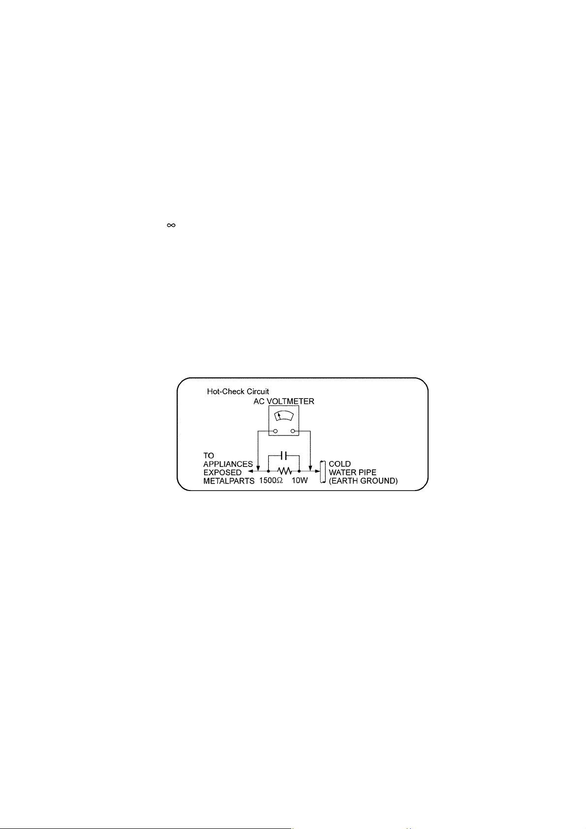
1.1.2. Leakage Current Hot Check
1. Plug the AC cord directly into the AC outlet. Do not use an isolation transformer for this check.
2. Connect a 1.5kΩ, 10 watts resistor, in parallel with a 0.15μF capacitors, between each exposed metallic part on the set and a
good earth ground such as a water pipe, as shown in Figure 1.
3. Use an AC voltmeter, with 1000 ohms/volt or more sensitivity, to measure the potential across the resistor.
4. Check each exposed metallic part, and measure the voltage at each point.
5. Reverse the AC plug in the AC outlet and repeat each of the above measurements.
6. The potential at any point should not exceed 0.75 volts RMS. A leakage current tester (Simpson Model 229 or equivalent)
may be used to make the hot checks, leakage current must not exceed 1/2 milliamp. In case a measurement is outside of the
limits specified, there is a possibility of a shock hazard, and the equipment should be repaired and rechecked before it is
returned to the customer.
Figure. 1
3
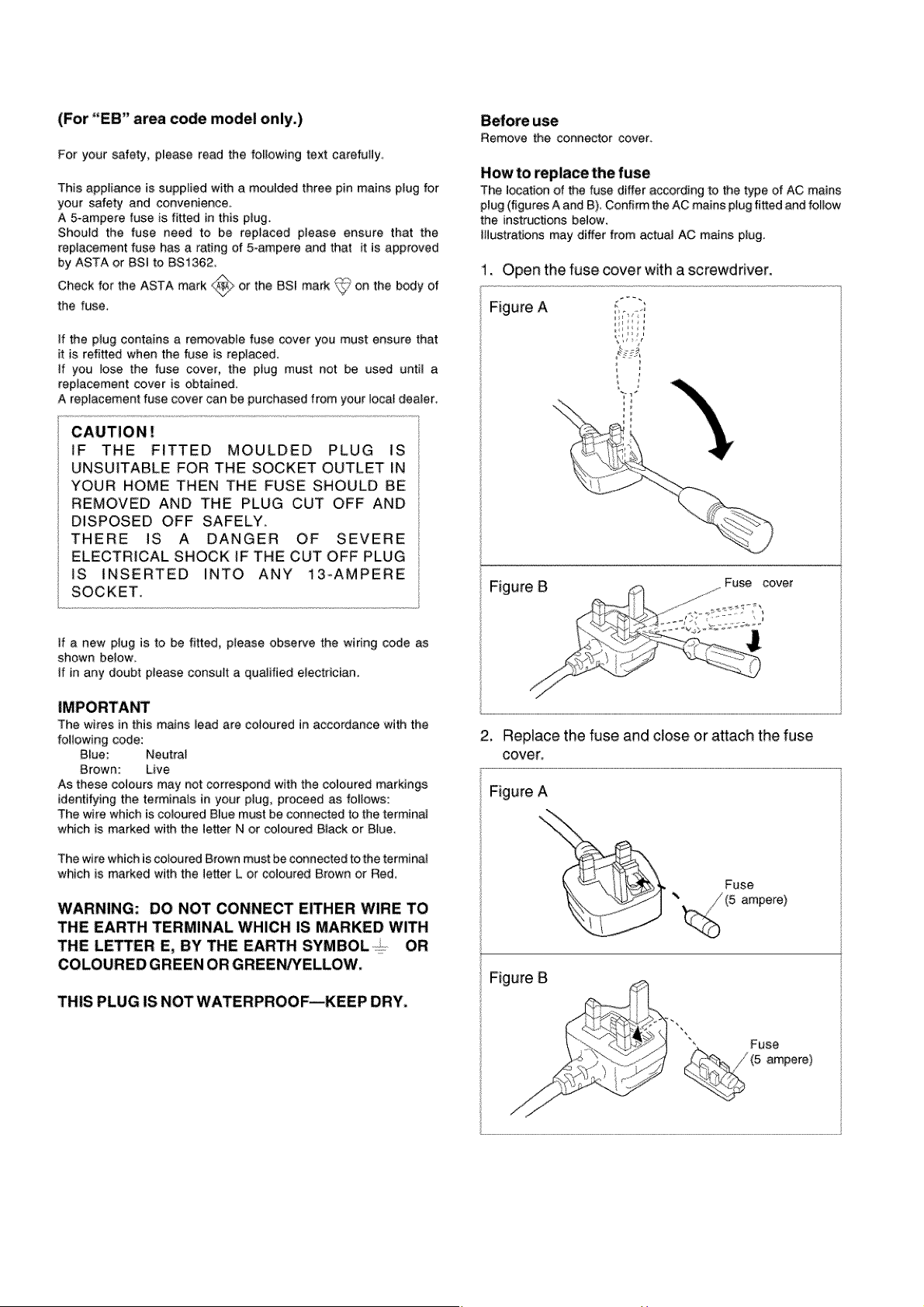
1.2. Caution for AC Cord
4
1.3. Before Repair and Adjustment
Caution : DO NOT SHORT-CIRCUIT DIRECTLY (with a screwdriver blade, for instance), as this may destroy solid state devices.
After repairs are completed, restore power gradually using a variac, to avoid overcurrent.
• Current consumption at AC 230 V, 50Hz in TUNER VOL. MIN mode should be (~300 mA) respectively.
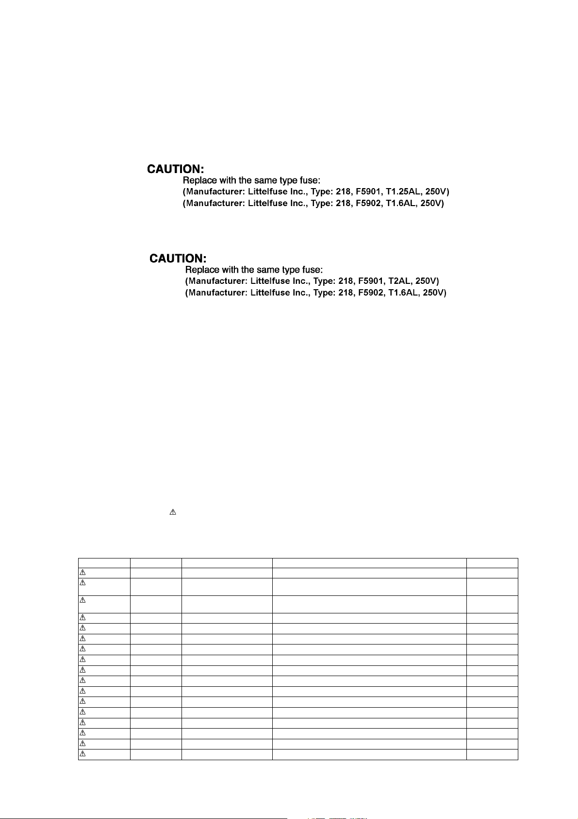
1.4. Caution For Fuse Replacement
1.4.1. For RX-D45
1.4.2. For RX-D50
1.5. Protection Circuitry
The protection circuitry may have operated if either of the following conditions are noticed:
• No sound is heard when the power is turned on.
• Sound stops during a performance.
The function of this circuitry is to prevent circuitry damage if, for example, the positive and negative speaker connection wires are
"shorted", or if speaker systems with an impedance less than the indicated rated impedance of the amplifier are used.
If this occurs, follow the procedure outlines below:
1. Turn off the power.
2. Determine the cause of the problem and correct it.
3. Turn on the power once again after one minute.
Note:
When the protection circuitry functions, the unit will not operate unless the power is first turned off and then on again.
1.6. Safety Part Information
Safety Parts List:
There are special components used in this equipment which are important for safety.
These parts are marked by in the Schematic Diagrams, Exploded View & Replacement Parts List. It is essential that these
critical parts should be replaced with manufacturer’s specified parts to prevent shock, fire or other hazards. Do not modify the
original design without permission of manufacturer.
Table 1
Safety Ref. No. Part No. Part Name & Description Remarks
401 RD-DAPX001-V TRAVERSE UNIT
A2 K2CZ3YY00005 AC CORD D50EB-S,
D45EB-W
A2 K2CQ2CA00007 AC CORD D50EG-S,
D45EG-W
A3 RQTX1035-E O/I BOOK (Du/Da/Sw) D50EG-S
A3 RQTX1034-D O/I BOOK (Ge/It/Fr) D50EG-S
A3 RQTX1041-Z O/I BOOK (En/Sp/Po/Cz) D50EG-S
A3 RQTX1148-B O/I BOOK (En) D50EB-S
A3 RQTX1031-D O/I BOOK (Ge/It/Fr) D45EG-W
A3 RQTX1032-E O/I BOOK (Du/Da/Sw) D45EG-W
A3 RQTX1040-Z O/I BOOK (En/Sp/Po/Cz) D45EG-W
A3 RQTX1147-B O/I BOOK (En) D45EB-W
PCB3 REPNT0063A POWER P.C.B. D45EB/EG-W
PCB3 REPNT0063B POWER P.C.B. D50EB/EG-S
T5902 G4C4BAH00003 TRANSFORMER D45EB/EG-W
T5903 G4C4BAH00002 BACK-UP TRANSFORMER D50EB/EG-S
T5904 G4C2AAH00002 TRANSFORMER
F5901 K5D122BLA014 FUSE D45EB/EG-W
5

Safety Ref. No. Part No. Part Name & Description Remarks
F5901 K5D202BLA013 FUSE D50EB/EG-S
F5902 K5D162BLA013 FUSE
JK5901 K2AA2B000014 JK AC INLET
L5901 ELF15N035AN LINE FILTER
RL5901 K6B1AEA00003 RELAY
Z5902 ERZVA5Z471 ZNR
FP4100 K5G502A00039 FUSE PROTECTOR
FP5903 K5G502A00039 FUSE PROTECTOR
ZA5901 K3GE1ZZ00001 FUSE HOLDER
ZA5902 K3GE1ZZ00001 FUSE HOLDER
ZA5903 K3GE1ZZ00001 FUSE HOLDER
ZA5904 K3GE1ZZ00001 FUSE HOLDER
6

2 Warning
2.1. Prevention of Electro Static Discharge (ESD) to Electrostatically Sensitive (ES) Devices
Some semiconductor (solid state) devices can be damaged easily by static electricity. Such components commonly are called Electrostatically Sensitive (ES) Devices. Examples of typical ES devices are integrated circuits and some field-effect transistors and
semiconductor “chip” components. The following techniques should be used to help reduce the incidence of component damage
caused by electrostatic discharge (ESD).
1. Immediately before handling any semiconductor component or semiconductor-equiped assembly, drain off any ESD on your
body by touching a known earth ground. Alternatively, obtain and wear a commercially available discharging ESD wrist strap,
which should be removed for potential shock reasons prior to applying power to the unit under test.
2. After removing an electrical assembly equiped with ES devices, place the assembly on a conductive surface such as aluminium foil, to prevent electrostatic charge build up or exposure of the assembly.
3. Use only a grounded-tip soldering iron to solder or unsolder ES devices.
4. Use only an anti-static solder remover device. Some solder removal devices not classified as “anti-static (ESD protected)” can
generate electrical charge sufficient to damage ES devices.
5. Do not use freon-propelled chemicals. These can generate electrical charges sufficient to damage ES devices.
6. Do not remove a replacement ES device from its protective package until immediately before you are ready to install it. (Most
replacement ES devices are packaged with leads electrically shorted together by conductive foam, aluminium foil or comparable conductive material).
7. Immediately before removing the protective material from the leads of a replacement ES device, touch the protective material
to the chassis or circuit assembly into which the device will be installed.
Caution :
Be sure no power is applied to the chassis or circuit, and observe all other safety precautions.
8. Minimize bodily motions when handling unpackaged replacement ES devices. (Otherwise harmless motion such as the
brushing together of your clothes fabric or the lifting of your foot from a carpeted floor can generate static electricity (ESD) suf-
ficient to damage an ES device).
7
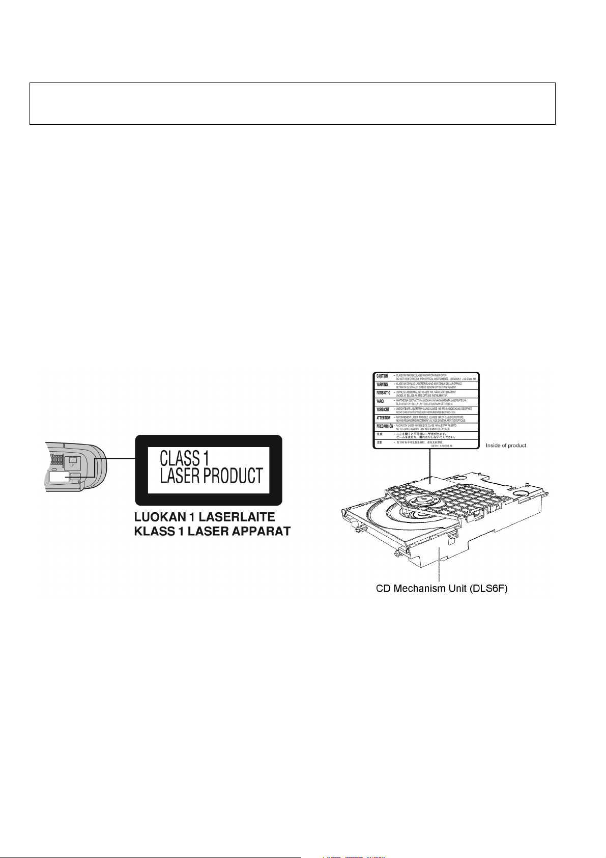
2.2. Precaution of Laser Diode
CAUTION!
THIS PRODUCT UTILIZES A LASER.
USE OF CONTROLS OR ADJUSTMENTS OR PERFORMANCE OF PROCEDURES OTHER THAN THOSE SPECIFIED HEREIN MAY RESULT
IN HAZARDOUS RADIATION EXPOSURE.
Caution:
This product utilizes a laser diode with the unit turned "on", invisible laser radiation is emitted from the pickup lens.
Wavelength: 795 nm (CD)
Maximum output radiation power from pickup: 100 μW/VDE
Laser radiation from the pickup unit is safety level, but be sure the followings:
1. Do not disassemble the pickup unit, since radiation from exposed laser diode is dangerous.
2. Do not adjust the variable resistor on the pickup unit. It was already adjusted.
3. Do not look at the focus lens using optical instruments.
4. Recommend not to look at pickup lens for a long time.
ACHTUNG :
Dieses Produkt enthält eine Laserdiode. Im eingeschalteten Zustand wird unsichtbare Laserstrahlung von der Lasereinheit
abgestrahlt.
Wellenlänge : 795 nm (CD)
Maximale Strahlungsleistung der Lasereinheit :100 μW/VDE
Die Strahlung an der Lasereinheit ist ungefährlich, wenn folgende Punkte beachtet werden:
1. Die Lasereinheit nicht zerlegen, da die Strahlung an der freigelegten Laserdiode gefährlich ist.
2. Den werkseitig justierten Einstellregler der Lasereinhit nicht verstellen.
3. Nicht mit optischen Instrumenten in die Fokussierlinse blicken.
4. Nicht über längere Zeit in die Fokussierlinse blicken.
8

2.3. Service caution based on Legal restrictions
2.3.1. General description about Lead Free Solder (PbF)
The lead free solder has been used in the mounting process of all electrical components on the printed circuit boards used for this
equipment in considering the globally environmental conservation.
The normal solder is the alloy of tin (Sn) and lead (Pb). On the other hand, the lead free solder is the alloy mainly consists of tin
(Sn), silver (Ag) and Copper (Cu), and the melting point of the lead free solder is higher approx.30 degrees C (86°F) more than that
of the normal solder.
Definition of PCB Lead Free Solder being used
The letter of “PbF” is printed either foil side or components side on the PCB using the lead free solder.
(See right figure)
Service caution for repair work using Lead Free Solder (PbF)
• The lead free solder has to be used when repairing the equipment for which the lead free solder is used.
(Definition: The letter of “PbF” is printed on the PCB using the lead free solder.)
• To put lead free solder, it should be well molten and mixed with the original lead free solder.
• Remove the remaining lead free solder on the PCB cleanly for soldering of the new IC.
• Since the melting point of the lead free solder is higher than that of the normal lead solder, it takes the longer time to melt the
lead free solder.
• Use the soldering iron (more than 70W) equipped with the temperature control after setting the temperature at 350±30 degrees
C (662±86°F).
Recommended Lead Free Solder (Service Parts Route.)
• The following 3 types of lead free solder are available through the service parts route.
RFKZ03D01K-----------(0.3mm 100g Reel)
RFKZ06D01K-----------(0.6mm 100g Reel)
RFKZ10D01K-----------(1.0mm 100g Reel)
Note
* Ingredient: Tin (Sn), 96.5%, Silver (Ag) 3.0%, Copper (Cu) 0.5%, Cobalt (Co) / Germanium (Ge) 0.1 to 0.3%
9
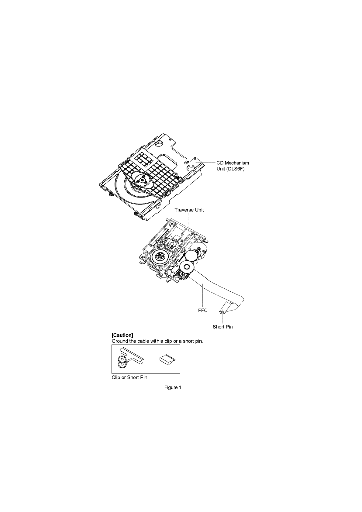
2.4. Handling Precaution for Traverse Unit
The laser diode in the optical pickup unit may break down due to static electricity of clothes or human body. Special care must be
taken avoid caution to electrostatic breakdown when servicing and handling the laser diode in the traverse unit.
2.4.1. Cautions to Be Taken in Handling the Optical Pickup Unit
The laser diode in the optical pickup unit may be damaged due to electrostatic discharge generating from clothes or human body.
Special care must be taken avoid caution to electrostatic discharge damage when servicing the laser diode.
1. Do not give a considerable shock to the optical pickup unit as it has an extremely high-precise structure.
2. To prevent the laser diode from the electrostatic discharge damage, the flexible cable of the optical pickup unit removed
should be short-circuited with a short pin or a clip.
3. The flexible cable may be cut off if an excessive force is applied to it. Use caution when handling the flexible cable.
4. The antistatic FPC is connected to the new optical pickup unit. After replacing the optical pickup unit and connecting the flexible cable, cut off the antistatic FPC.
2.4.2. Grounding for electrostatic breakdown prevention
Some devices such as the CD player use the optical pickup (laser diode) and the optical pickup will be damaged by static electricity
in the working environment. Proceed servicing works under the working environment where grounding works is completed.
2.4.2.1. Worktable grounding
1. Put a conductive material (sheet) or iron sheet on the area where the optical pickup is placed, and ground the sheet.
10
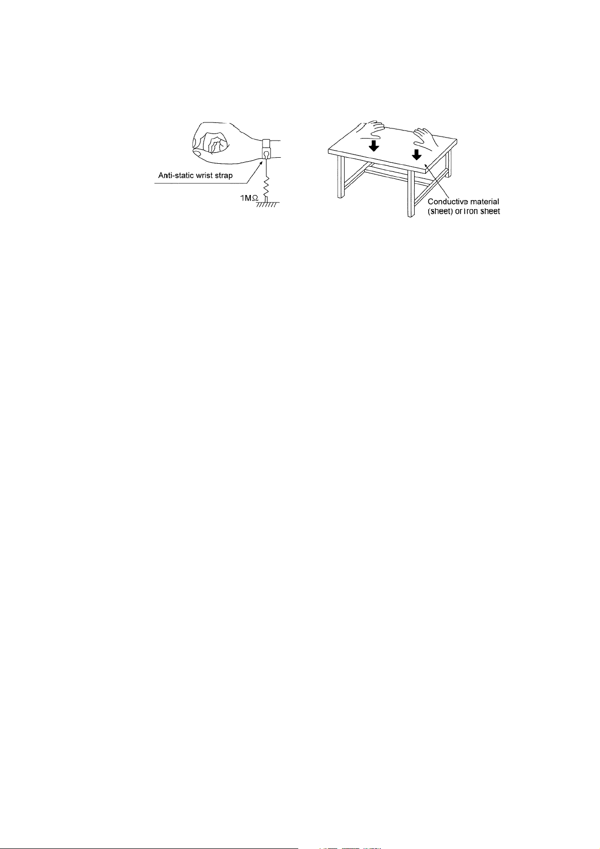
2.4.2.2. Human body grounding
1. Use the anti-static wrist strap to discharge the static electricity form your body (Figure 2).
Figure 2
11

3 Service Navigation
3.1. Service Information
This service manual contains technical information which will allow service personnel’s to understand and service this model.
Please place orders using the parts list and not the drawing reference numbers.
If the circuit is changed or modified, this information will be followed by supplement service manual to be filed with original service
manual.
• CD Mechanism Unit (DLS6F):
1) This model uses CD Mechanism Unit (DLS6F).
• Micro-processor:
1) The following components are supplied as an assembled part.
• Micro-processor IC, (IC2100) is supplied as assembled part (RFKWMD45EG-W).
12

4 Specifications
(RX-D45)
I Amplifier Section
RMS output power stereo mode
Front Ch (both channels
driven)
Total RMS stereo mode power 4 W
I FM/AM Tuner, Terminal Section
Preset station FM 16 stations
Frequency Modulation (FM)
Frequency range 87.50 MHz to 108.00 MHz (50 kHz
Amplitude Modulation (A M)
Frequency range 522 kHz to 1629 kHz (9 kHz step)
Headphone jack
Term in al Stereo, 3.5 mm jack (32 Ω)
I Disc Section
Disc played (8 cm or 12 cm) CD-Audio, CD-R/W (CD-DA)
Sampling frequency 44.1 kHz
Decoding 16 bit linear
Pick up
Wavelength 795 nm (CD)
Laser power CLASS 1 (CD)
Number of channels 2 channel, stereo
Wow and flutter Less than possible measurement
I Cassette Deck Section
Track system 4 track, 2 channel
Monitor system Variable sound monitor
Head
Record/playback Solid permalloy head
Motor DC servo motor
Recording system AC bias 84 kHz
Erase system Multi pole magnet
Tape speed 4.8 cm/s
Overall frequency response (+3 dB, -6 dB) at DECK OUT
NORMAL 50 Hz to 12 kHz
S/N ratio 50 dB (A weighted)
Wow and flutter 0.18% (WRMS)
Fast forward and rewind time Approx. 120 seconds with C-60 cas-
2 W per channel (8 Ω), 1 kHz, 10%
THD
AM 16 stations
step)
520 kHz to 1630 kHz (10 kHz step)
data
sette tape
Power consumption in standby mode: 0.8 W (approximate)
Notes :
1. Specifications are subject to change without notices.
Mass and dimensions are approximate.
2. Total harmonic distortion is measured by the digital spectrum analyzer.
(RX-D50)
I Amplifier Section
RMS output power stereo mode
Front Ch (both channels
driven)
Total RMS stereo mode power 6 W
I FM/AM Tuner, Terminal Section
Preset station FM 16 stations
Frequency Modulation (FM)
Frequency range 87.50 MHz to 108.00 MHz (50 kHz
Amplitude Modulation (AM)
Frequency range 522 kHz to 1629 kHz (9 kHz step)
Headphone jack
Terminal Stereo, 3.5 mm jack (32 Ω)
Music port (front) jack
Sensitivity 100 mV, 4.7 kΩ
Terminal Stereo, 3.5 mm jack
I Disc Section
Disc played (8 cm or 12 cm)
(1) CD-Audio (CD-DA)
(2) CD-R/RW (CD-DA, MP3* formatted disc)
(3) MP3*
* MPEG-1 Layer 3, MPEG-2 Layer 3
Bit rate
MP3 32 kbps to 320 kbps
Sampling frequency
CD 44.1 kHz
MP3 32 kHz, 44.1 kHz, 48 kHz
Decoding 16 bit linear
Pick up
Wavelength 795 nm (CD)
Laser power CLASS 1 (CD)
Number of channels 2 channel, stereo
Wow and flutter Less than possible measurement
3 W per channel (4 Ω), 1 kHz, 10%
THD
AM 16 stations
step)
520 kHz to 1630 kHz (10 kHz step)
data
I Speaker Section
Ty pe 1 way, 2 speaker system (Bass
reflex)
Speaker(S)
Full range 8 cm cone type
Impedance 8 Ω
I General
Power supply
AC 230 V, 50 Hz (EG)
230 V to 240 V, 50 Hz (EB)
Battery 12 V (8 x LR14, C)
Memory back-up 6 V (4 x R6/LR6, AA)
Power consumption 12 W (EG)
13 W (EB)
Dimensions (W x H x D) 408 mm x 148 mm x 255 mm
Mass 3.19 kg without batteries
Operating temperature range
Operating humidity range 35% to 80 % RH (no condensation)
0°C to +40°C
I Cassette Deck Section
Track system 4 track, 2 channel
Monitor system Variable sound monitor
Head
Record/playback Solid permalloy head
Motor DC servo motor
Recording system AC bias 84 kHz
Erase system Multi pole magnet
Tape speed 4.8 cm/s
Overall frequency response (+3 dB, -6 dB) at DECK OUT
NORMAL 50 Hz to 12 kHz
S/N ratio 50 dB (A weighted)
Wow and flutter 0.18% (WRMS)
Fast forward and rewind time Approx. 120 seconds with C-60 cas-
sette tape
I Speaker Section
Type 2 way, 2 speaker system (Bass
reflex)
13

Speaker(S)
Full range 8 cm cone type
Tweeter 1.5 cm ceramic tweeter type
Impedance 4 Ω
I General
Power supply
AC 230 V, 50 Hz
Battery 12 V (8 x LR14, C)
Memory back-up 6 V (4 x R6/LR6, AA)
Power consumption 14 W
Dimensions (W x H x D) 408 mm x 148 mm x 255 mm
Mass 3.28 kg without batteries
Operating temperature range 0°C to +40°C
Operating humidity range 35% to 80 % RH (no condensation)
Power consumption in standby mode: 0.8 W (approximate)
Notes :
1. Specifications are subject to change without notices.
Mass and dimensions are approximate.
2. Total harmonic distortion is measured by the digital spectrum analyzer.
14
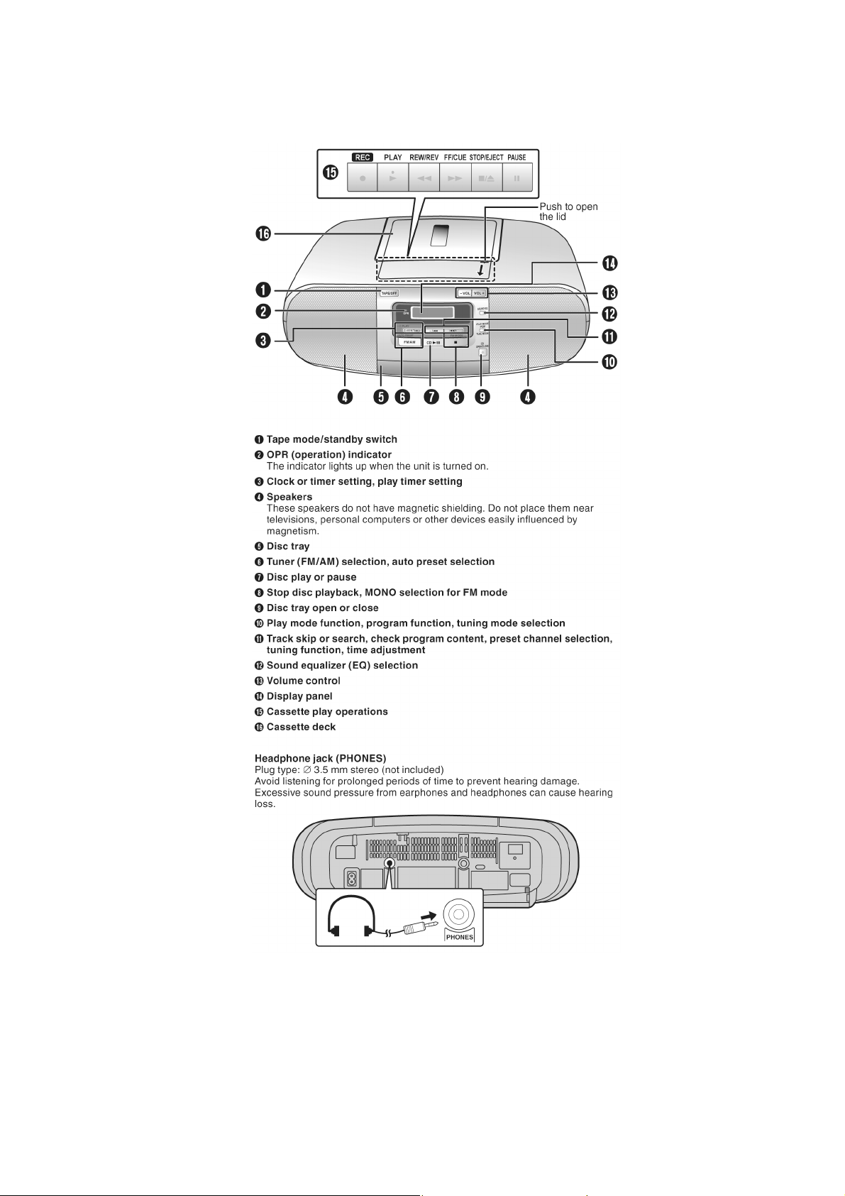
5 Location of Controls and Components
5.1. Main Unit Key Button Operations (RX-D45)
15
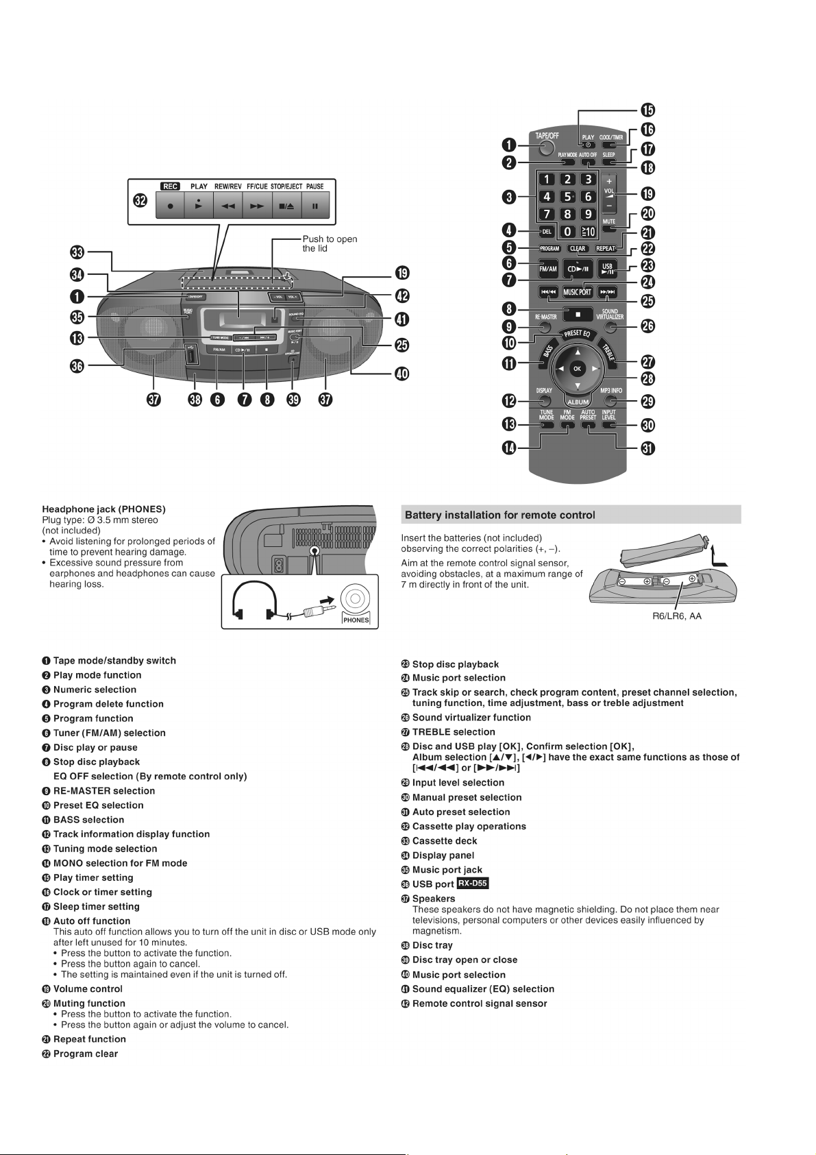
5.2. Main Unit and Remote Control Key Button Operations (RX-D50)
16
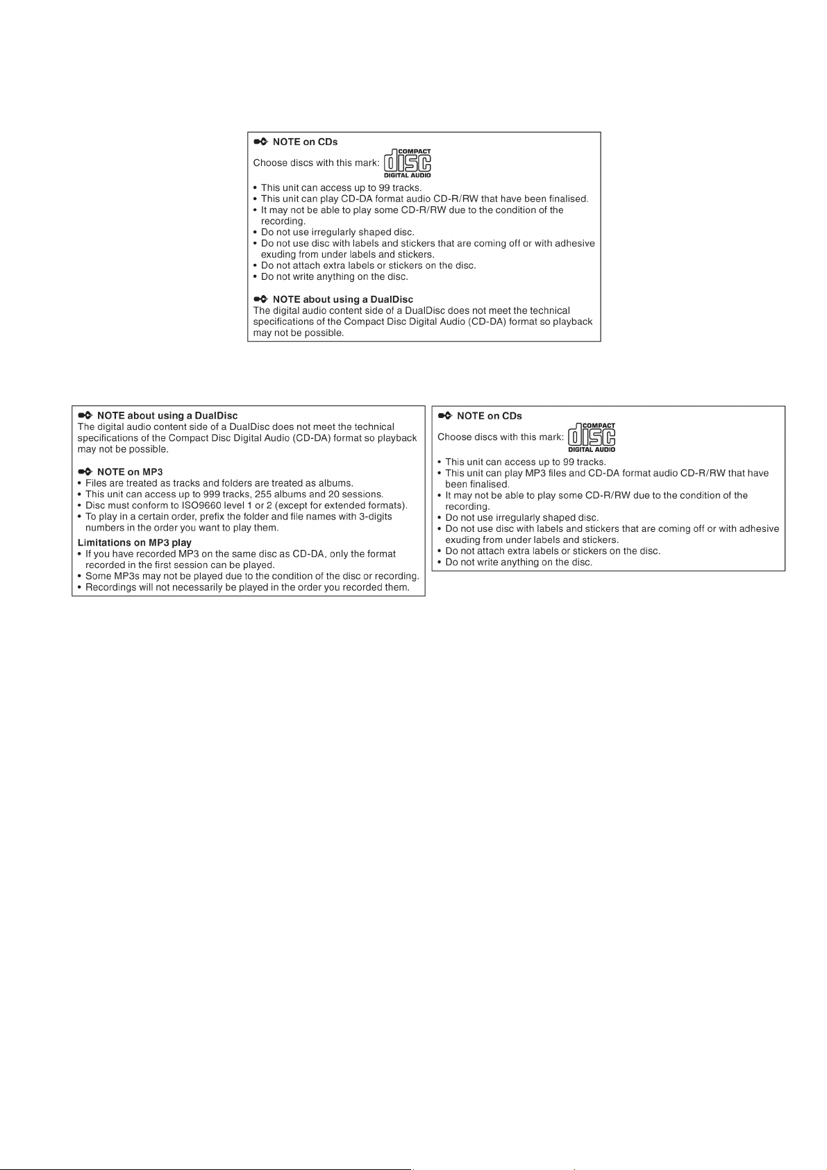
5.3. Disc Information
5.3.1. Disc Information (RX-D45)
5.3.2. Disc Information (RX-D50)
17
6 Self Diagnostic and Doctor Mode Setting
This unit is equiped with features of self diagnostic & doctor mode setting for checking the functions & reliability.
6.1. Self Diagnostic Mode
6.1.1. Self Diagnostic Table
Item FL display Key operation
Mode name Description
Self Diagnostic Mode To enter into self diagnostic
checking
1. Select CD mode
(Ensure no CD inserted).
㪁㩷㪁㩷㪁㩷䋺㩷㪜㫉㫉㫆㫉㩷㪺㫆㪻㪼
Error code information Error code will display
System will perform a check on
any unusual/error code from the
memory
Example:
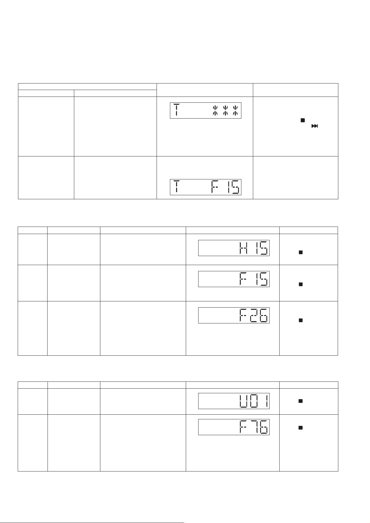
6.1.2. Self Diagnostic Error Code 1 (For CD)
Error Code
H15 CD Open SW
F15 CD REST SW
Diagnostic Contents Description of error
Abnormal
Abnormal
During normal operation CD OPEN
SW On fail to be detected with 4
sec. Error No. shall be clear by
force or during cold start.
CD traverse position intial setting
operation failsafe counter (1000
ms) waiting for REST SW to turn
on. Error No. shall be clear by
force or during cold start.
FL display
2. Press and hold [ ] for
2 seconds follow by [ /+] on
main unit.
To exit, press [TAPE/OFF] on
main uint.
1. In self diagnosis mode.
2. Press [STOP] for on main unit.
To exit, press [TAPE/OFF] on
main uint.
Remarks
For CD Mechanism Unit
(DLS6F) (For Traverse).
Press [ ] on main unit
for next error
For CD Mechanism Unit
(DLS6F) (For Traverse).
Press [ ] on main unit
for next error
F26 Communication
between CD servo
LSI and micro-p
abnormal.
CD function DTMS command, after
system setting, If SENSE = 'L'
cannot be detected. Memory shall
contain F26 code. After Power on,
CD function shall continue, error
display shall be "NO DISC".
Error No. shall be clear by force or
cold start.
6.1.3. Self Diagnostic Error Code 2 (For Power Supply)
Error Code
U01 Battery Low Detect the Battery when Battery is
F76 Abnormality in the
Diagnostic Contents Description of error
Low.
output voltage of
stabilized power
supply
In normal operation when DCDET1
is detected "L" (Low) for two
consecutive times, F76 is
displayed on FL for 1 second and
after that PCONT will be turned to
"L" (Low). This is due to any of the
DC voltages (+9V, +7V, -7V, +5V,
+5.3V etc.) not available.
FL display
For CD Mechanism Unit
(DLS6F) (For Traverse).
Press [ ] on main unit
for next error
Remarks
For Power.
Press [ ] on main unit
for next error
For Power.
Press [ ] on main unit
for next error
18
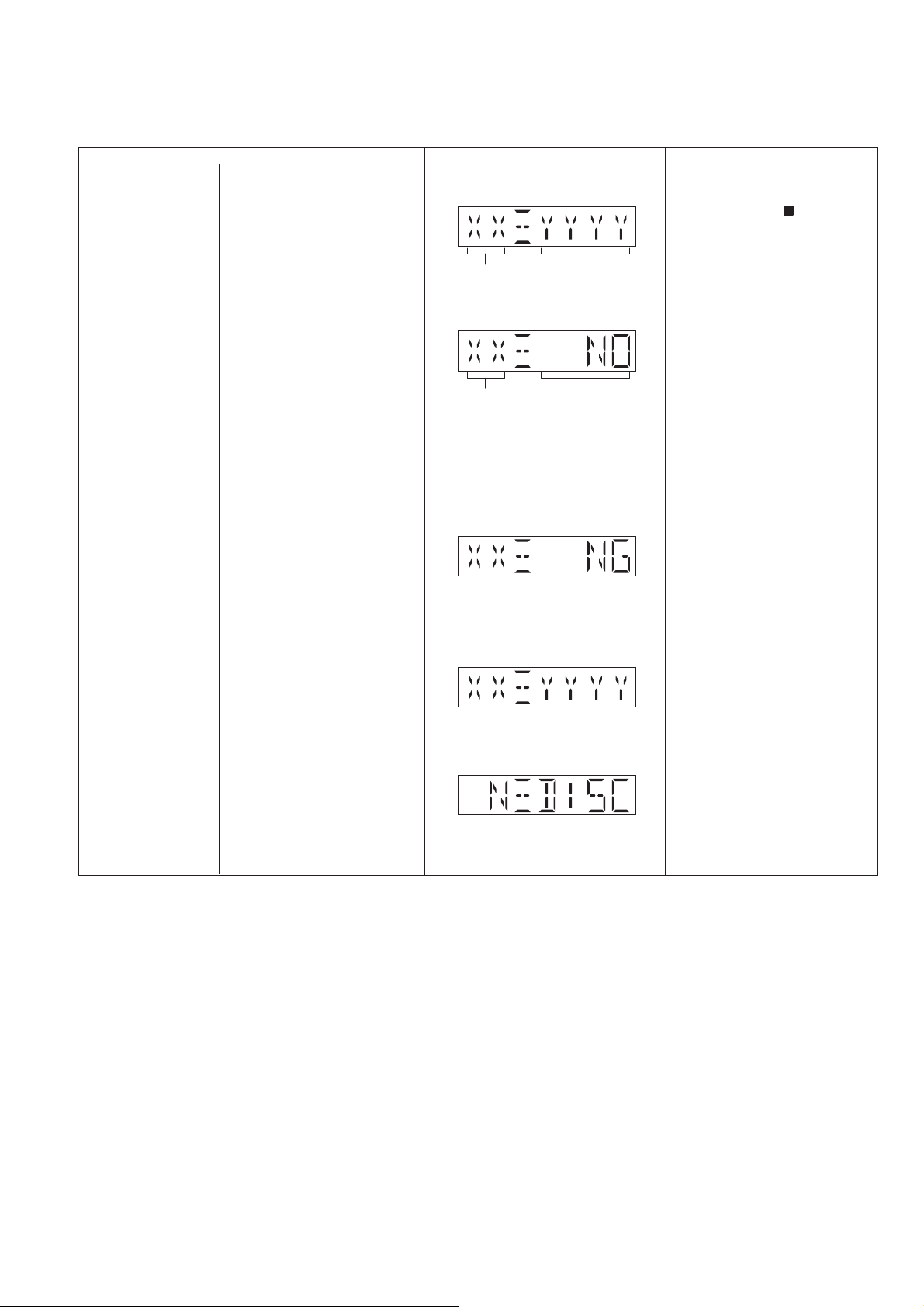
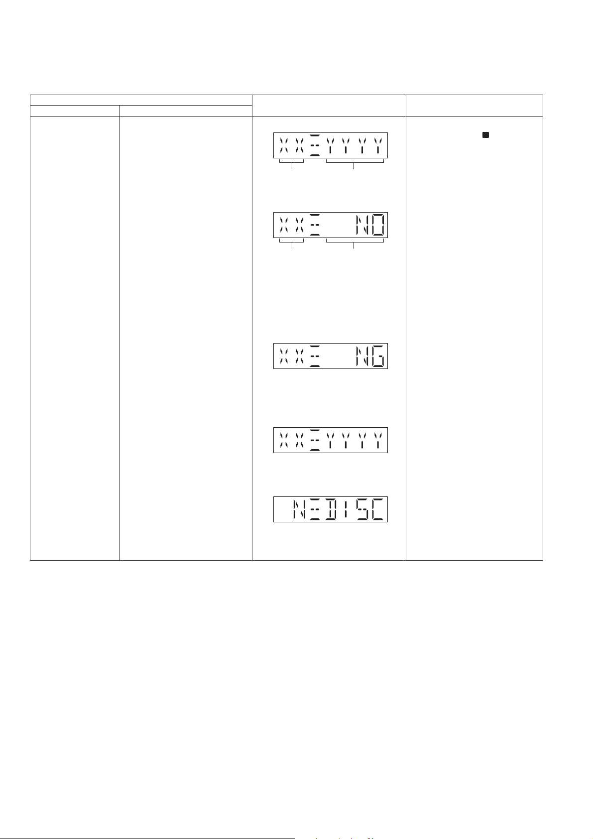
6.2. Doctor Mode (For RX-D45)
6.2.1. Doctor Mode Table 1
Item FL display Key operation
Mode name Description
Doctor Mode In any mode:
To enter into Doctor Mode for
checking of various items and
displaying EEPROM and firmware
version.
Note: The micro-processor
version as shown is an example.
It will be revise when there is an
updates.
FL Display sequence
Display 1 > 2
Version Display
(Display 1)
(DEC)
Checksum : (Condition 1)
Checksum
(HEX)
1. Press and hold [ ] on main unit
follow by [-VOL] on main unit.
To exit, press [TAPE/OFF] on
main uint.
Version Display
(DEC)
(a) If there is NO EEPROM header
string OR
(b) If there is no EEPROM ( no data is
received by micro-processor) [NO] is
displayed.
Checksum : (Condition 2)
If the version of the EEPROM does not
match or not working properly [NG] is
display.
Checksum : (Condition 3)
If the EEPROM version matches,
checksum [YYYY] is displayed.
The Checksum of EEPROM and
firmware version will be display for 2
sec.
Check sum
(HEX)
(Display 2)
19
6.2.2. Doctor Mode Table 2
Item FL display Key operation
Mode name Description
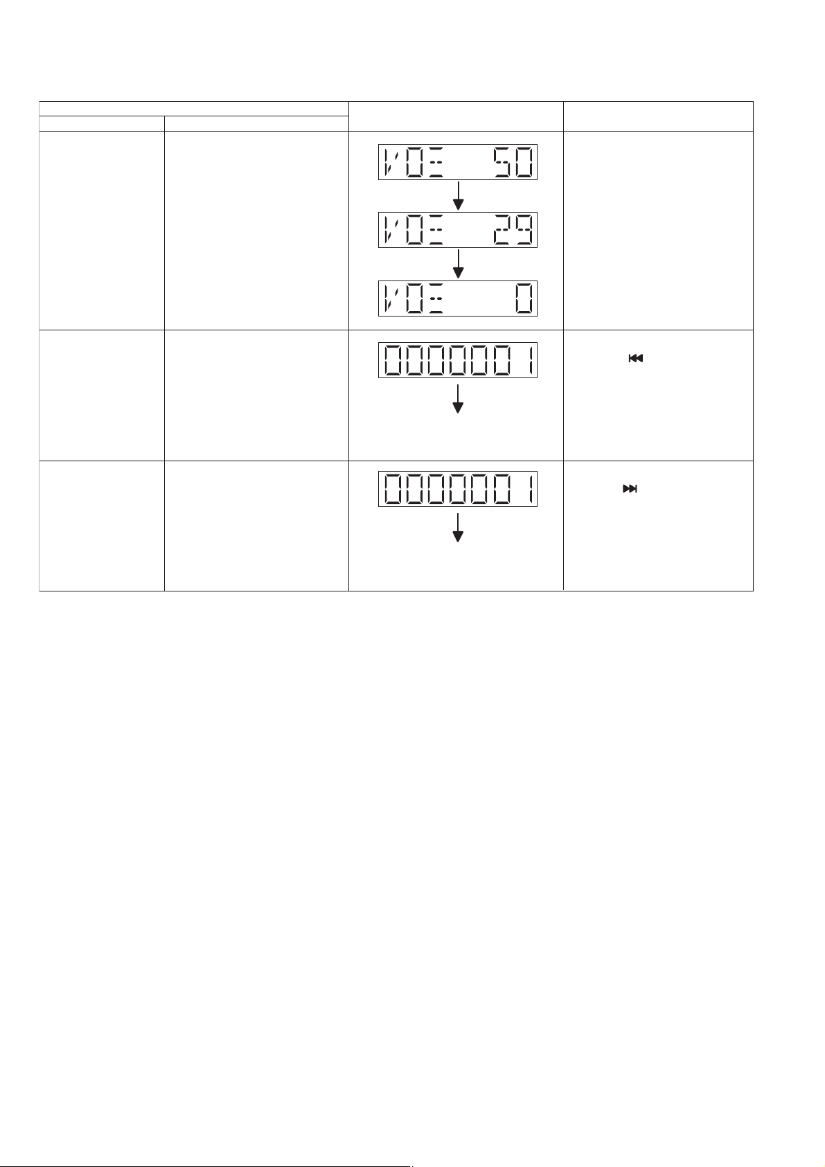
Volume Setting In Doctor Mode:
To check for volume setting during
this mode, Bass & treble is set to
0dB & EQ is switch off.
Display for 1 sec
Display for 1 sec
1. Select to FM mode and Press
[SOUND EQ] on main unit.
To exit, press [TAPE/OFF] on
main uint.
CD Loading Test Mode
(DLS6F)
CD Combination Test
Mode (DLS6F)
To determine the reliability of CD
Loading unit.
To check for the Open/Close
operation for the CD loading unit.
It fails when there is abnormality
in opening or closing.
A combination of CD loading &
traverse unit test.
The counter will increment by one.
When reach 9999999 will change to
0000000
The counter will increment by one.
When reach 9999999 will change to
0000000
In Doctor Mode:
1. Press [-/ ] on main unit.
To exit, press [TAPE/OFF] on
main uint.
(Refer to section 6.2.3. for more
information).
In Doctor Mode:
1. Press [ /+] on main unit.
To exit, press [TAPE/OFF] on
main uint.
(Refer to section 6.2.4. for more
information).
20
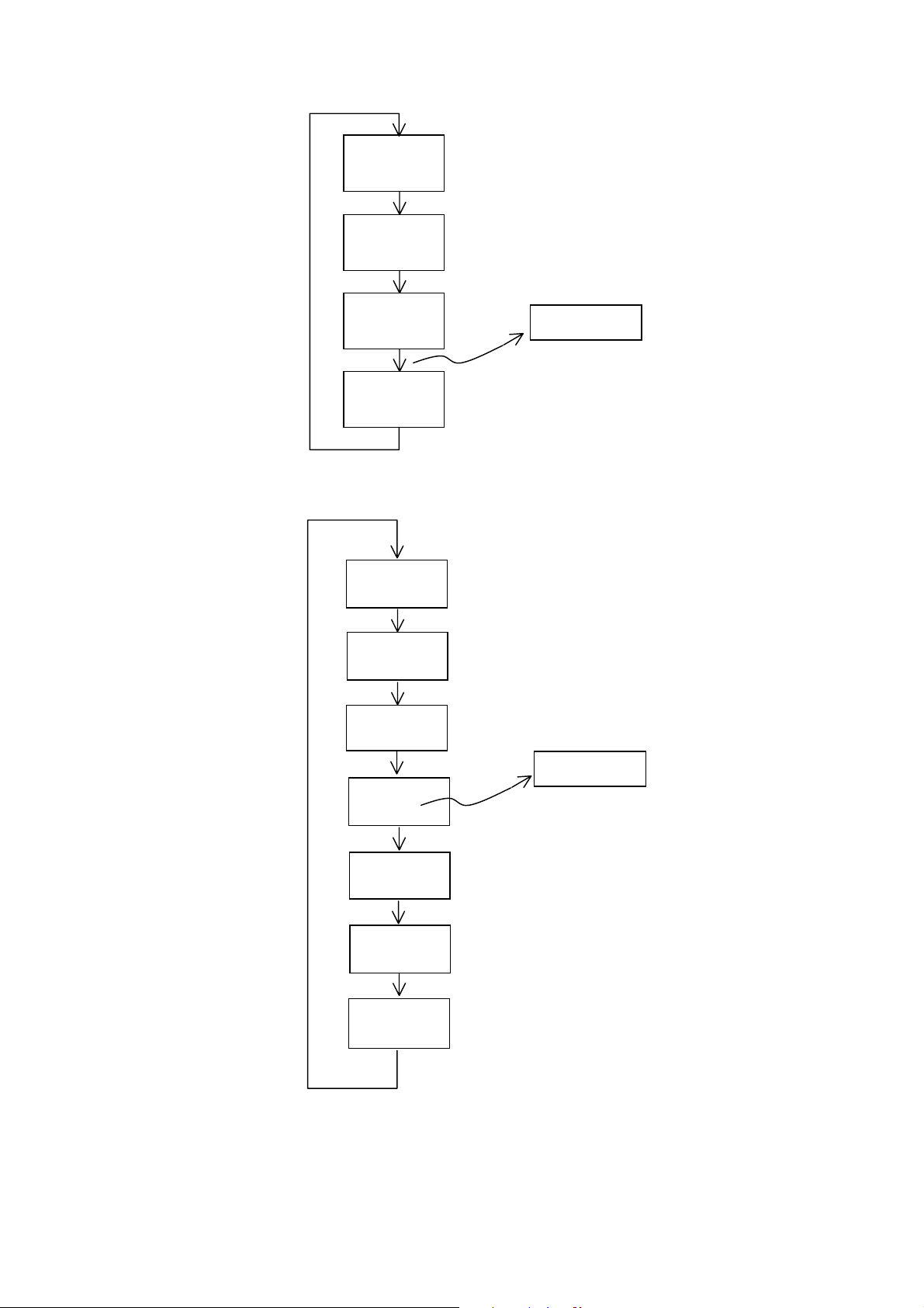
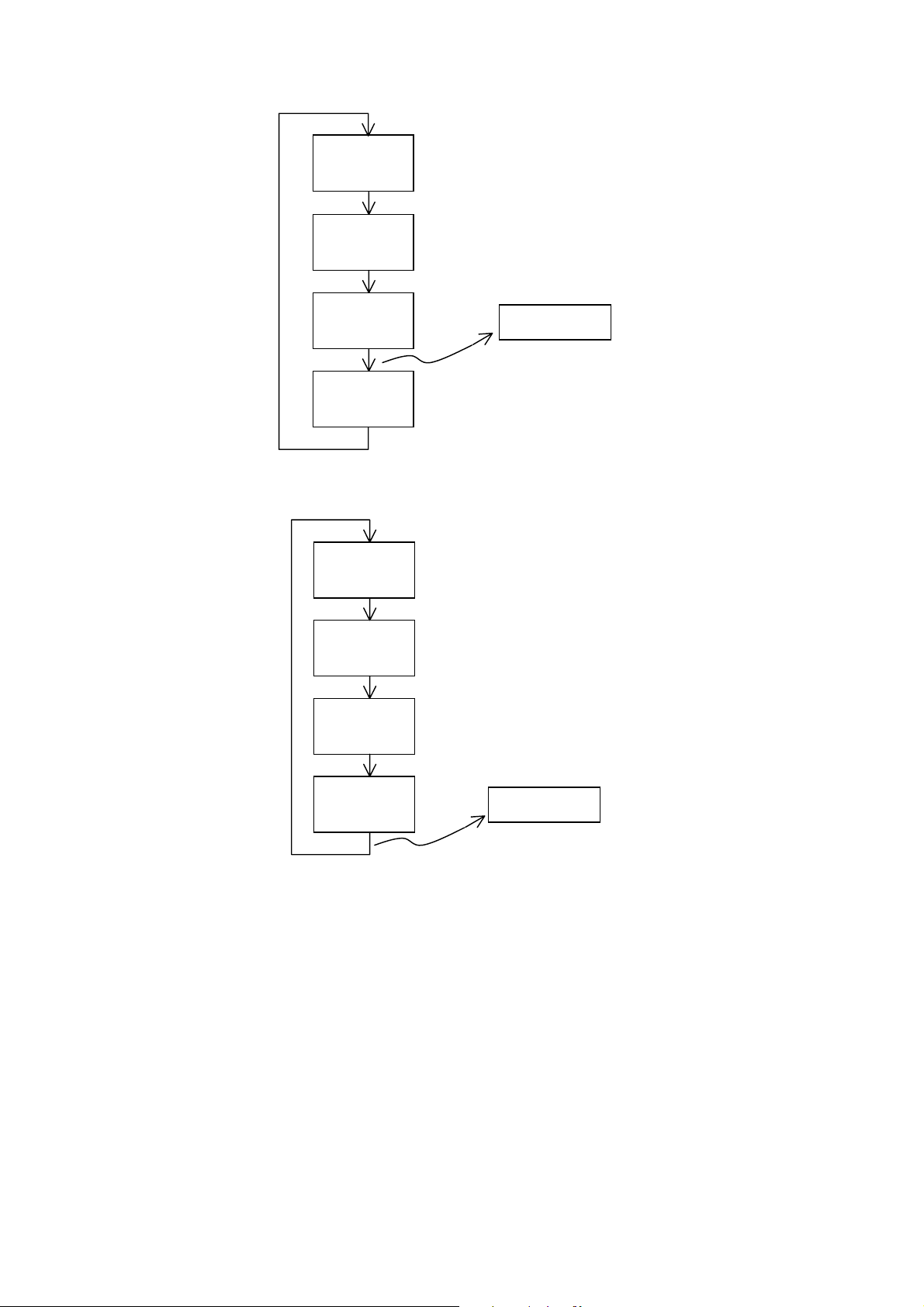
6.2.3. CD Loading Test Mode
OPEN
Operation
OPEN wait
for 1 s
CLOSE
Operation
CLOSE
wait for 4s
6.2.4. CD Combination Test Mode
First Track
Access
First Track
Play 10 s
Last Track
Access
Count Up
Last Track
Play 10 s
OPEN
Operation
OPEN wait
for 1 s
CLOSE
Operation
Count Up
21
6.3. Doctor Mode (For RX-D50)
6.3.1. Doctor Mode Table 1
Item FL display Key operation
Mode name Description
Doctor Mode In any mode:
To enter into Doctor Mode for
checking of various items and
displaying EEPROM and firmware
version.
(Display 1)
1. Press and hold [ ] on main
unit follow by [4] and [7] on
remote control.
Note: The micro-processor
version as shown is an example.
It will be revise when there is an
updates.
FL Display sequence
Display 1 > 2
Version Display
(DEC)
Checksum : (Condition 1)
Version Display
(DEC)
(a) If there is NO EEPROM header
string OR
(b) If there is no EEPROM ( no data is
received by micro-processor) [NO] is
displayed.
Checksum : (Condition 2)
If the version of the EEPROM does not
match or not working properly [NG] is
display.
Checksum : (Condition 3)
Checksum
(HEX)
Check sum
(HEX)
To exit, press [TAPE/OFF] on
main uint.
If the EEPROM version matches,
checksum [YYYY] is displayed.
(Display 2)
The Checksum of EEPROM and
firmware version will be display for 2
sec.
22
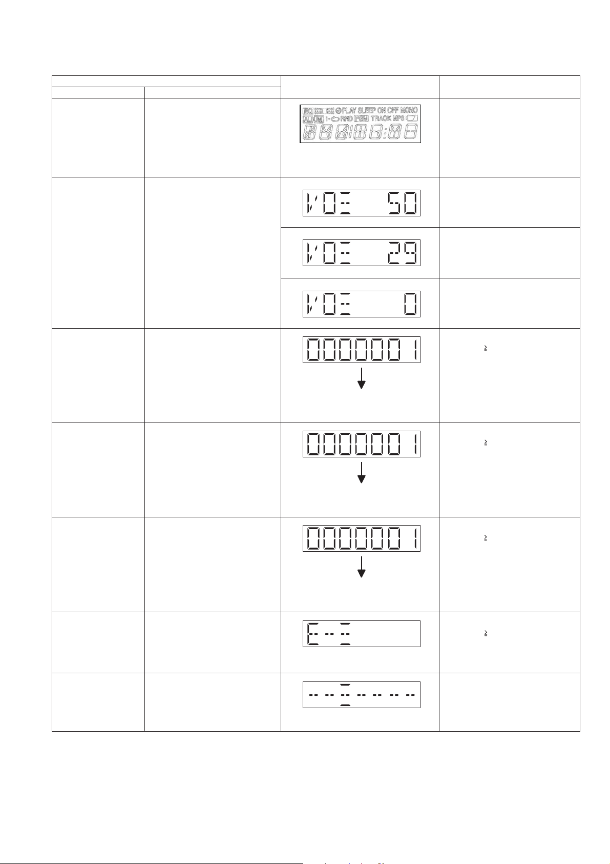
6.3.2. Doctor Mode Table 2
Item FL display Key operation
Mode name Description
FL Display Test In Doctor Mode:
To check the FL segments display
(All segments will light up)
1. Press [AUTO OFF] on remote
control.
To cancel, press [0] on remote
control.
To exit, press [TAPE/OFF] on main
uint.
Volume Setting In Doctor Mode:
To check for volume setting during
this mode, Bass & treble is set to
0dB & EQ is switch off.
1. Press [7] on remote control.
To exit, press [TAPE/OFF] on main
uint.
In Doctor Mode:
1. Press [8] on remote control.
To exit, press [TAPE/OFF] on main
uint.
In Doctor Mode:
1. Press [9] on remote control.
To exit, press [TAPE/OFF] on main
uint.
CD Loading Test Mode
(DLS6F)
CD Traverse Unit Test
Mode (DLS6F)
To determine the reliability of CD
Loading unit.
To check for the Open/Close
operation for the CD loading unit.
It fails when there is abnormality
in opening or closing.
To check for the traverse unit
operation. In this mode, the first &
last track is access & read. (TOC).
It fails when TOC is not completed
by IOS or the traverse is out of
focus.
The counter will increment by one.
When reach 9999999 will change to
0000000
The counter will increment by one.
When reach 9999999 will change to
0000000
In Doctor Mode:
1. Press [ 10], [1], [1] on remote
control.
To exit, press [TAPE/OFF] on main
uint.
(Refer to section 6.3.3. for more
information).
In Doctor Mode:
1. Press [ 10], [1], [2] on remote
control.
To exit, press [TAPE/OFF] on main
uint.
(Refer to section 6.3.4. for more
information).
CD Combination Test
Mode (DLS6F)
CD Self-Adjustment
(AJST) Result Display
Cold Start In Doctor Mode:
A combination of CD loading &
traverse unit test.
The following shall be displayed
for 2.5 secs. The result shall
correspond to the condition met
as shown.
To activate cold start upon next
AC power up.
The counter will increment by one.
When reach 9999999 will change to
0000000
Display of auto adjustment result
In Doctor Mode:
1. Press [ 10], [1], [3] on remote
control.
To exit, press [TAPE/OFF] on main
uint.
(Refer to section 6.3.5. for more
information).
In Doctor Mode:
1. Press [ 10], [1], [4] on remote
control.
To exit, press [TAPE/OFF] on main
uint.
1. Press [SLEEP] on remote
control.
To exit, press [TAPE/OFF] on main
uint.
23
6.3.3. CD Loading Test Mode
OPEN
Operation
OPEN wait
for 1 s
6.3.4. CD Traverse Unit Test
CLOSE
Operation
CLOSE
wait for 4s
First Track
Access
First Track
Play 5 s
Last Track
Access
Count Up
Last Track
Play 5 s
Count Up
24
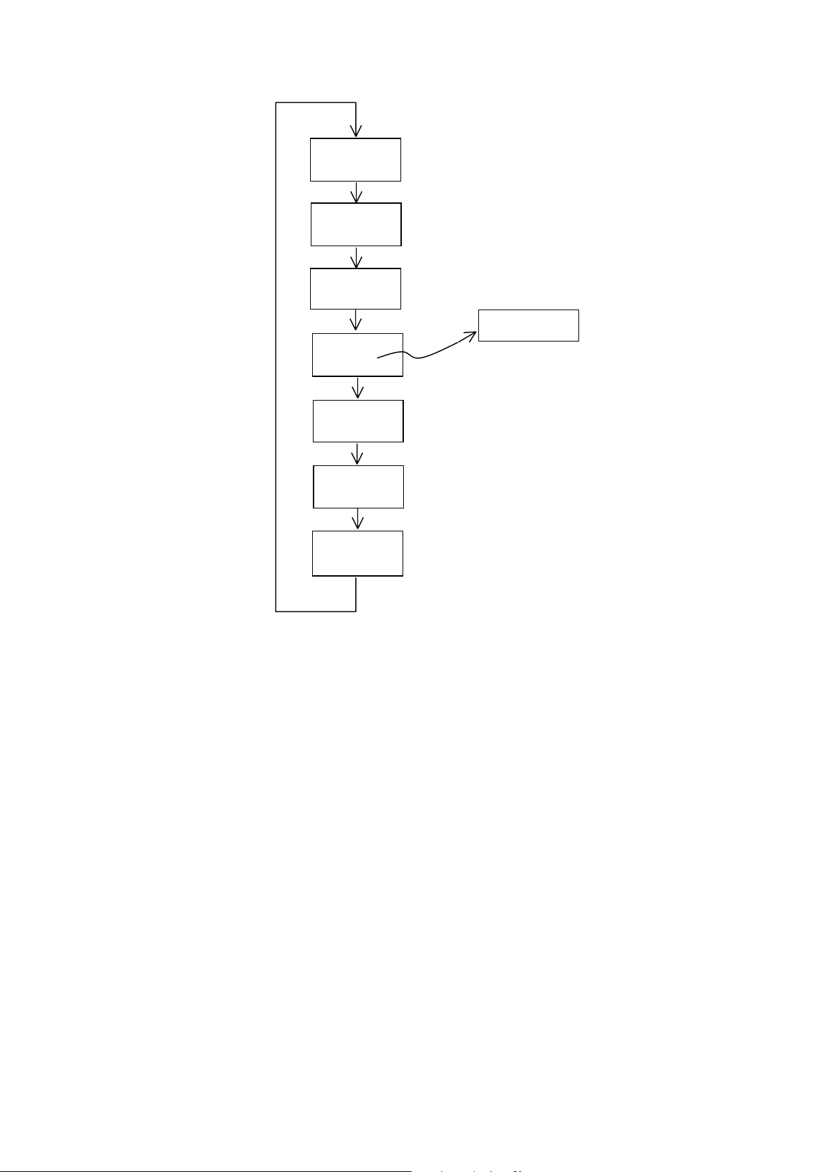
6.3.5. CD Combination Test Mode
First Track
Access
First Track
Play 10 s
Last Track
Access
Last Track
Play 10 s
Operation
Count Up
OPEN
OPEN wait
for 1 s
CLOSE
Operation
25

7 Service Fixture & Tools
Prepare service tools before proccess service position.
Service Tools Remarks
Deck P.C.B. (JW830) - Main P.C.B. (CN2104) REXN0084 (10P cable)
Panel P.C.B. (ZJ903) - Main P.C.B. (CN4104) REXN0082 (4P cable)
Panel P.C.B. (CN900) - Main P.C.B. (CN2105) REXN0080 (10P cable)
26
8 Disassembly and Assembly Instructions
Caution Note:
• This section describes the disassembly and/or assembly procedures for all major printed circuit boards & main components for the unit. (You may refer to the section of “Main components and P.C.B Locations” as described in the service
manual)
• Before carrying out the disassembly process, please ensure all the safety precautions & procedures are followed.
• During the disassembly and/or assembly process, please handle with care as there may be chassis components with
sharp edges.
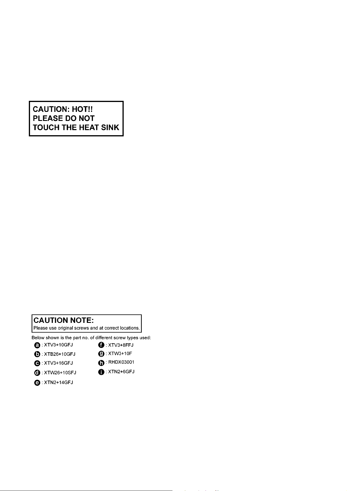
• Avoid touching heatsinks due to its high temperature after prolong use. (See caution as described below)
• During disassembly and assembly, please ensure proper service tools, equipments or jigs is being used.
• During replacement of component parts, please refer to the section of “Replacement Parts List” as described in the
service manual.
• Select items from the following indexes when disassembly or replacement are required.
• Disassembly of Top Cabinet Assembly
• Disassembly of Music Port P.C.B. (for RX-D50 only)
• Disassembly of Front Panel Assembly
• Disassembly of Panel P.C.B., Standby P.C.B. and Volume P.C.B.
• Disassembly of Woofer Speaker (SP1)
• Disassembly of Woofer Speaker (SP2)
• Disassembly of CD Lid
• Disassembly of Deck Mechanism Unit
• Disassembly of Deck P.C.B.
• Disassembly of Cassette Lid
• Disassembly of Mecha Bottom Cover
• Disassembly of Power P.C.B.
• Disassembly of Main P.C.B.
• Replacement of Transistor (Q4107)
• Replacement of Power IC (IC4101)
• Disassembly of CD Mechanism Unit
• Disassembly of CD Servo P.C.B.
• Disassembly of Battery (1) P.C.B.
• Disassembly of Battery (2) P.C.B.
27

8.1. Disassembly flow chart
The following chart is the procedure for disassembling the casing and inside parts for internal inspection when carrying out the servicing.
To assemble the unit, reverse the steps shown in the chart below.
28
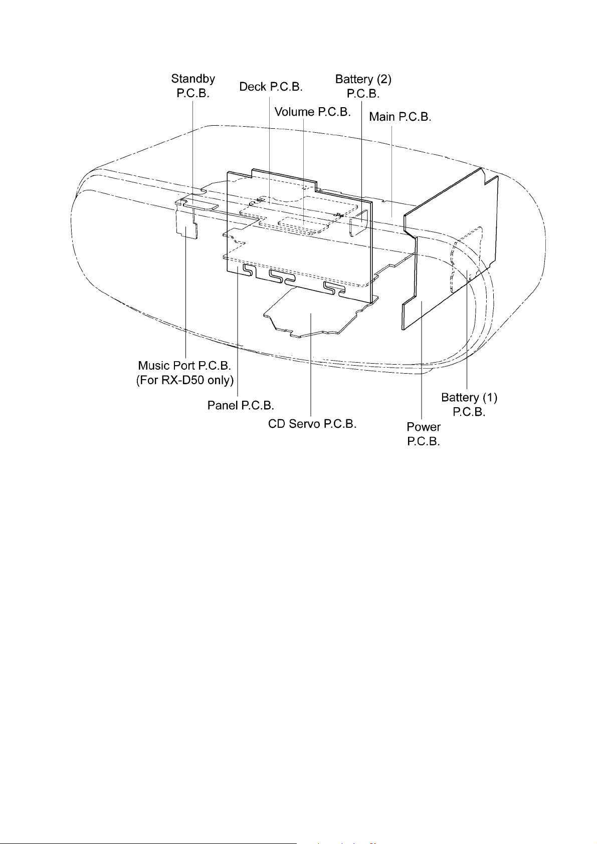
8.2. Main Parts Location Diagram
29
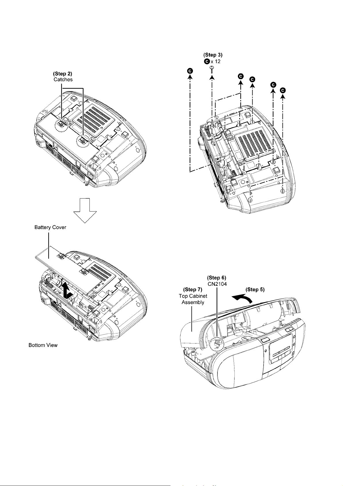
8.3. Disassembly of Top Cabinet Assembly
Step 1 : Upset the unit.
Step 2 : Release 2 catches to remove Battery Cover.
Step 3 : Remove 12 screws.
Step 4 : Upset the unit.
Step 5 : Slightly lift up the Top Cabinet Assembly as arrow
shown.
Step 6 : Detach 10P cable at the connector (CN2104) on Main
P.C.B..
Step 7 : Remove the Top Cabinet Assembly.
30
 Loading...