

Panasonic RX-CS45GS, RX-CS45GS1 Service manual
A
ORDER NO. MD0603094C3
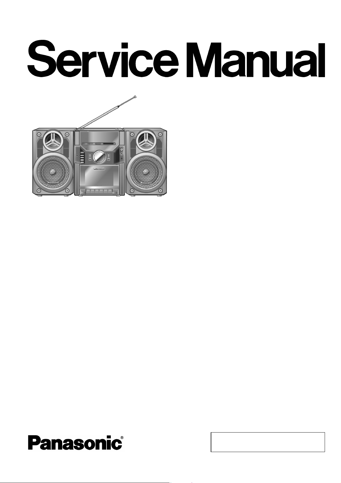
Portable Stereo Component System
RX-CS45GC
RX-CS45GU
RX-CS45GS
RX-CS45GS1
Colour
(K)....Black Type
Specifications
n RADIO
Frequency range
FM 87.5-108 MHz
MW 520-1610 kHz
SW1 2.3-7.0 MHz
SW2 7.0-22.0 MHz
n TAPE RECORDER
Track system Stereo
Monitor system Variable sound monitor
Recording system AC bias(84 kHz)
Erasing system Multi pole Magnet
Frequency range
Normal 40 Hz-12 kHz
n GENERAL
Power requirement
C 110-127 V/220-240 V, 50/60 Hz
Power consumption 22 W
Power consumption in standby
mode
Battery 12 V (Eight R20/LR20, D, UM-1
2.75 W
batteries)
DC IN 12-13.2 V
Power output
PMPO 200 W
RMS(max.)
(DC12V/AC117V)9Wx2/8.3Wx2
Speakers 10 cm 8 Ω
Full range 2 Ceramic Tweeter
Jacks
Input sensitivity / Input inpedance
CD/LINE IN
Normal 316 mV, 33 kΩ
High 100 mV, 12 kΩ
Output impedance
Headphones 32Ω
Dimensions (W x H x D) 518 x 260 x 225 mm
Main unit 210 x 255 x 230 mm
Speaker box 163 x 260 x 210 mm
Mass 6.2 kg with batteries
5.38 kg without batteries
Notes:
1. Specifications are subject to change without notice.
2. Mass and dimensions are approximate.
© 2006 Matsushita Electric Industrial Co. Ltd.. All
rights reserved. Unauthorized copying and
distribution is a violation of law.
RX-CS45GC / RX-CS45GU / RX-CS45GS / RX-CS45GS1
CONTENTS
Page Page
1 Safety Precautions 3
1.1. General Guidelines
1.2. Caution for AC Cord (For GS only)
1.3. Before Use
1.4. Before Repair and Adjustment
1.5. Protection Circuitry
2 Prevention of Electro Static Discharge (ESD) to
Electrostatically Sensitive (ES) Devices
3 Warning
3.1. Service caution based on legal restrictions
4 Accessories
5 Operating Instructions Procedures
5.1. Main Operation Buttons
6 Assembling and Disassembling
6.1. Caution
6.2. Disassembly Procedures
6.3. Disassembly Flow chart
6.4. Main Parts Location Diagram
6.5. Before Disassembly
6.6. Disassembly of Front Cabinet
6.7. Disassembly Equalizer P.C.B., CD/Line In P.C.B. and
Main P.C.B.
6.8. Disassembly of Deck Mechanism Unit
6.9. Disassembly of Tuner P.C.B.
10
10
10
10
11
11
12
12
14
14
3
4
5
5
5
6
7
7
8
9
9
6.10. Disassembly of Power P.C.B./ Battery P.C.B.
6.11. Disassembly of Speaker
7 Service Positions
7.1. Checking Procedures
7.2. Checking and Repairing of the Equalizer P.C.B., CD/Line
In P.C.B. and Main P.C.B.
7.3. Checking and Repairing of the Deck P.C.B.
7.4. Checking and Repairing of the Tuner P.C.B.
7.5. Checking and Repairing of the Power P.C.B.
8 Adjustment Procedures
8.1. Tuner Section
8.2. Deck Section
8.3. Alignment Point
9 Wiring Diagrams
10 Notes of Schematic Diagrams
11 Schematic Diagrams
12 Printed Circuit Board Diagrams
13 Illustration of ICs, Transistors and Diodes
14 Exploded Views
14.1. Deck Mechanism Parts Location (RAA0945-2N)
14.2. Cabinet Parts Location
14.3. Packaging Materials and Accessories
15 Replacement Parts List
15
16
17
17
17
18
19
19
20
20
21
22
23
25
27
29
31
32
33
35
37
39
2

RX-CS45GC / RX-CS45GU / RX-CS45GS / RX-CS45GS1
1 Safety Precautions
1.1. General Guidelines
1. When servicing observe the original lead dress. If a short circuit is found, replace all parts which have been overheated or
damaged by the short circuit.
2. After servicing, ensure that all the protective devices such as insulation barriers, insulation papers shields are properly installed.
3. After servicing, check for leakage current to prevent from being exposed to shock hazards.
1.1.1. Leakage Current Cold Check
1. Unplug the AC cord and connect a jumper between the two prongs on the plug.
2. Using an ohmmeter measure the resistance value, between the jumpered AC plug and each exposed metallic cabinet part on
the equipment such as screwheads, connectors, control shafts, etc. When the exposed metallic part has a return path to the
chassis the reading should be between 1MΩ and 5.2MΩ.
When the exposed metal does not have a return path to the chassis, the reading must be
1.1.2. Leakage Current Hot Check (See Fig. 1)
.
Fig. 1
1. Plug the AC cord directly into the AC outlet. Do not use an isolation transformer for this check.
2. Connect a 1.5kΩ, 10 watts resistor, in parallel with a 0.15µF capacitors, between each exposed metallic part on the set and a
good earth ground such as a water pipe, as shown in Fig. 1.
3. Use an AC voltmeter, with 1000 ohms/volt or more sensitivity, to measure the potential across the resistor.
4. Check each exposed metallic part, and measure the voltage at each point.
5. Reverse the AC plug in the AC outlet and repeat each of the above measurements.
6. The potential at any point should not exceed 0.75 volts RMS. A leakage current tester (Simpson Model 229 or equivalent) may
be used to make the hot checks, leakage current must not exceed 1/2 milliamp. Should the measurement outside of the limits
specified, there is a possibility of a shock hazard, and equipment should be examine and reached before it is returned to the
customer.
3
RX-CS45GC / RX-CS45GU / RX-CS45GS / RX-CS45GS1
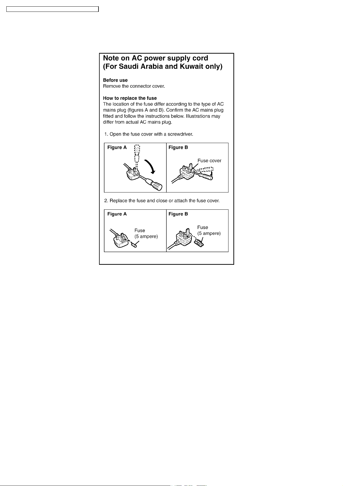
1.2. Caution for AC Cord (For GS only)
4

RX-CS45GC / RX-CS45GU / RX-CS45GS / RX-CS45GS1
1.3. Before Use
Be sure to disconnect the mains cord before adjusting the voltage selector. Use a minus (-) screwdriver to set the voltage selector
(on the rear panel) to the voltage setting for the area in which the unit will be sure.
(If the power supply in your area is 220 V to 240 V, set to “220 V to 240 V” position.)
Note that this unit will be seriously damaged if this setting is not made correctly. (There is no voltage selector for some countries;
the correct voltage is already set.)
1.4. Before Repair and Adjustment
DO NOT SHORT-CIRCUIT DIRECTLY (with a screwdriver blade, for instance), as this may destroy solid state devices.
After repairs are completed, restore power gradually using a variac, to avoid overcurrent.
Current consumption in AC 110 V,127 V, 220 V or 240 V at 50 Hz in NO SIGNAL mode at (volume minimum) should be ~ 90 mA,
~ 110 mA, ~ 50 mA or ~ 60 mA respectively.
Battery current consum ption (12 V DC) is ~ 250 mA.
1.5. Protection Circuitry
The protection circuitry may have operated if either of the following conditions are noticed:
· No sound is heard when the power is turned on.
· Sound stops during a performance.
The function of this circuitry is to prevent circuitry damage if, for example the positive and negative speaker connection wires are
“shorted”, or if speaker with an impedance less than the indicated rated impedance of the amplifier are used.
If this occurs, follow the procedure outlines below:
1. Turn off the power.
2. Determine the cause of the problem and correct it.
3. Turn on the power once again after one minute.
Note:
When the protection circuitry functions, the unit will not operate unless the power is first turned off and then on again.
5

RX-CS45GC / RX-CS45GU / RX-CS45GS / RX-CS45GS1
2 Prevention of Electro Static Discharge (ESD) to
Electrostatically Sensitive (ES) Devices
Some semiconductor (solid state) devices can be damaged easily by electricity. Such components commonly are called
Electrostatically Sensitive (ES) Devices. Examples of typical ES devices are integrated circuits and some field-effect transistors and
semiconductor “chip” components. The following techniques should be used to help reduce the incidence of component damage
caused by electro static discharge (ESD).
1. Immediately before handling any semiconductor component or semiconductor-equipped assembly, drain off any ESD on your
body by touching a known earth ground. Alternatively, obtain and wear a commercially available discharging ESD wrist strap,
which should be removed for potential shock reasons prior to applying power to the unit under test.
2. After removing an electrical assembly equipped with ES devices, place the assembly on a conductive surface such as
aluminium foil, to prevent electrostatic charge build up or exposu re of the assembly.
3. Use only a grounded-tip soldering iron to solder or unsold er ES devices.
4. Use only an anti-static solder remover device. Some solder removal devices not classified as “anti-static (ESD protected)” can
generate electrical charge to damage ES devices.
5. Do not use freon-propelled chemicals. These can generate electrical charges sufficient to damage ES devices.
6. Do not remove a replacement ES device from its protective package until immediately before you are ready to install it. (Most
replacement ES devices are packaged with leads electrically shorted together by conductive foam, aluminium foil or
comparable conductive material).
7. Immediately before removing the protective material from the leads of a replacement ES device, touch the protective material
to the chassis or circuit assembly into which the device will be installed.
Caution:
Be sure no power is applied to the chassis or circuit, and observe all other safety precautions.
8. Minimize body motions when handling unpackaged replacement ES devices. (Otherwise harmless motion such as the brushing
together of your clothes fabric or the lifting of your foot from a carpeted floor can generate static electricity (ESD) sufficient to
damage an ES device).
6
RX-CS45GC / RX-CS45GU / RX-CS45GS / RX-CS45GS1
3 Warning
3.1. Service caution based on legal restrictions
3.1.1. General description about Lead Free Solder (PbF)
The lead free solder has been used in the mounting process of all electrical components on the printed circuit boards used for this
equipment in considering the globally environmental conservation.
The normal solder is the alloy of tin (Sn) and lead (Pb). On the other hand, the lead free solder is the alloy mainly consists of tin
(Sn), silver (Ag) and Copper (Cu), and the melting point of the lead free solder is higher approx.30 degrees C (86°F) more than that
of the normal solder.
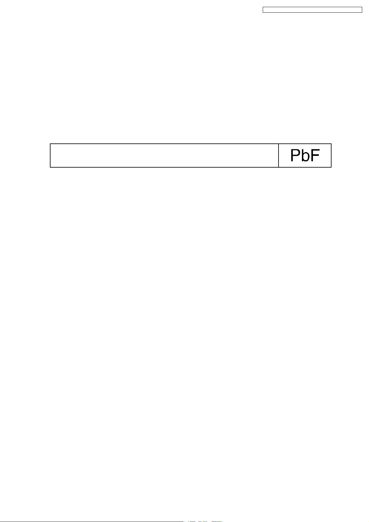
Definition of PCB Lead Free Solder being used
The letter of “PbF” is printed either foil side or components side on the PCB using the lead free solder.
(See right figure)
Service caution for repair work using Lead Free Solder (PbF)
· The lead free solder has to be used when repairing the equipment for which the lead free solder is used.
(Definition: The letter of “PbF” is printed on the PCB using the lead free solder.)
· To put lead free solder, it should be well molten and mixed with the original lead free solder.
· Remove the remaining lead free solder on the PCB cleanly for soldering of the new IC.
· Since the melting point of the lead free solder is higher than that of the normal lead solder, it takes the longer time to melt
the lead free solder.
· Use the soldering iron (more than 70W) equipped with the temperature control after setting the temperature at 350±30
degrees C (662±86°F).
Recommended Lead Free Solder (Service Parts Route.)
· The following 3 types of lead free solder are available through the service parts route.
RFKZ03D01K-----------(0.3mm 100g Reel)
RFKZ06D01K-----------(0.6mm 100g Reel)
RFKZ10D01K-----------(1.0mm 100g Reel)
Note
* Ingredient: Tin (Sn), 96.5%, Silver (Ag) 3.0%, Copper (Cu) 0.5%, Cobalt (Co) / Germanium (Ge) 0.1 to 0.3%
7

RX-CS45GC / RX-CS45GU / RX-CS45GS / RX-CS45GS1
4 Accessories
AC Cord... (For GC/GS1/G U)
AC Cord... (For GS only)
8
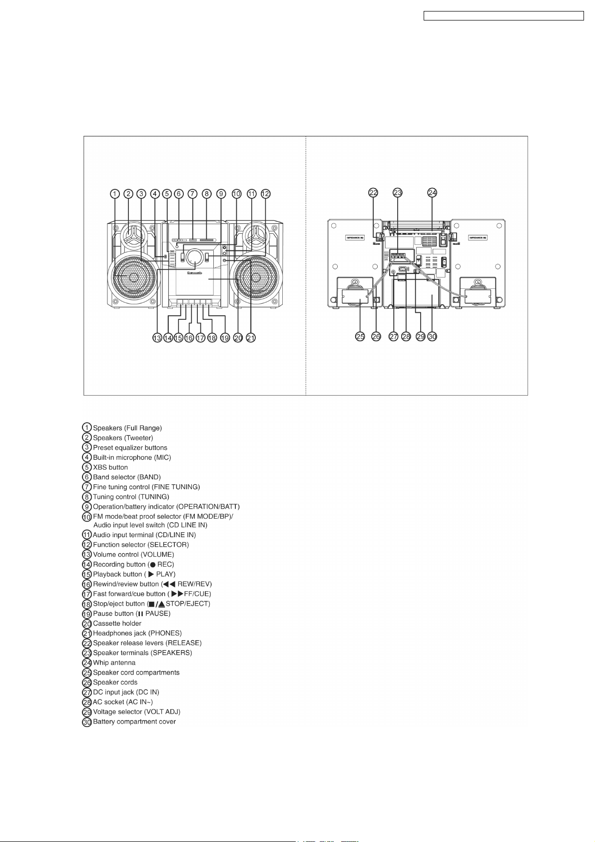
5 Operating Instructions Procedures
5.1. Main Operation Buttons
RX-CS45GC / RX-CS45GU / RX-CS45GS / RX-CS45GS1
9
RX-CS45GC / RX-CS45GU / RX-CS45GS / RX-CS45GS1
6 Assembling and Disassembling
6.1. Caution
“Attention Servic er”
Some chassis components may have sharp edges.
Be careful when disassembly and servicing.
1. This section describes procedure for checking the operation of the major printed circuit boards and replacing the main
components.
2. For reassembly after operation checks or replacement, reverse the respective procedures.
3. Select items from the following index when checks or replacement are required.
4. Refer to the Part No.on the page of “Parts Location and Replacement Parts List” if necessary.
6.2. Disassembly Procedures
· Disassembly of the Front Cabinet
· Disassembly of the Equalizer P.C.B., CD/Line In P.C.B. and Main P.C.B.
· Disassembly of the Deck Mechanism Unit and Deck P.C.B.
· Disassembly of the Tuner P.C.B.
· Disassembly of the Power P.C.B./ Battery P.C.B.
· Disassembly of the Speaker
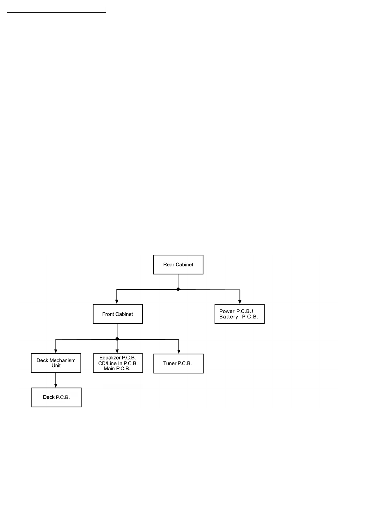
6.3. Disassembly Flow chart
The following chart is the procedure for disassembly the casing and inside parts for internal inspection when carrying out the
servicing.
To assemble the unit, reverse the steps shown in the chart as below.
10
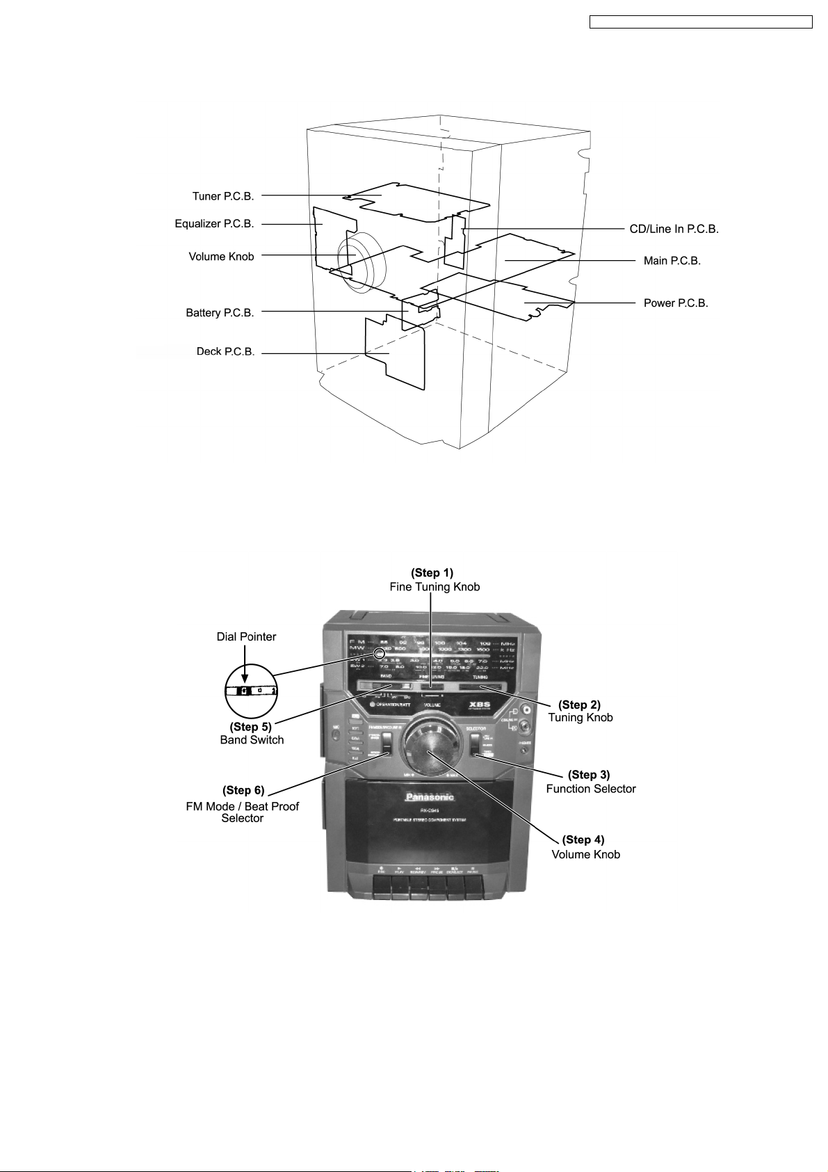
6.4. Main Parts Location Diagram
RX-CS45GC / RX-CS45GU / RX-CS45GS / RX-CS45GS1
6.5. Before Disassembly
Important notes: Ensure all the settings as below are set before proceeding to the disassemble steps.
Step 1: Set fine tuning knob to centre.
Step 2: Set tuning knob until dial pointer line up at “0” point graduation as shown in the figure.
Step 3: Set function selector to OFF.
Step 4: Set volume knob to minimum.
Step 5: Set band switch to SW2.
Step 6: Set FM mode/ beat proof selector to normal.
11
RX-CS45GC / RX-CS45GU / RX-CS45GS / RX-CS45GS1
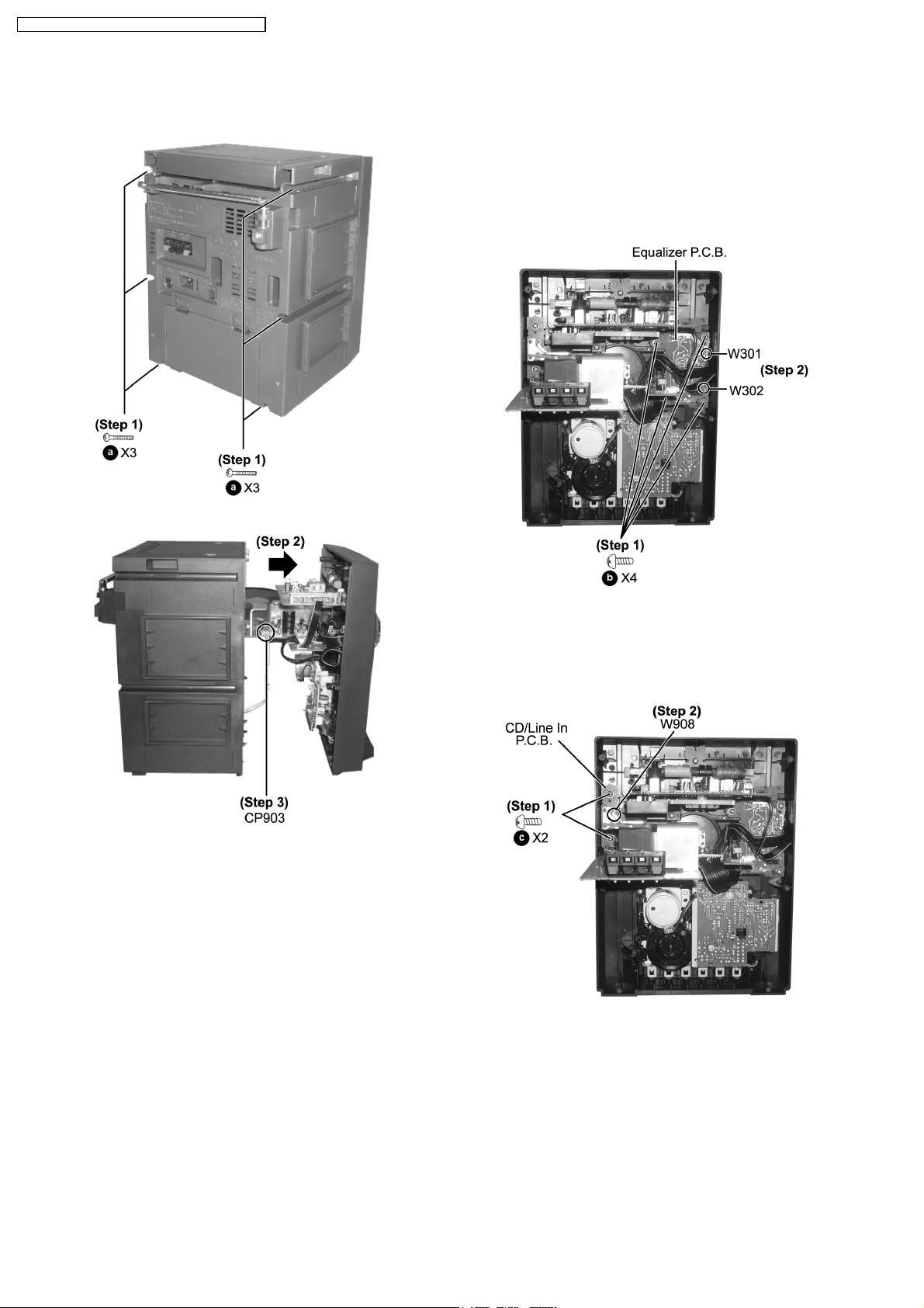
6.6. Disassembly of Front Cabinet
Step 1: Remove 6 screws.
6.7. Disassembly Equalizer P.C.B.,
CD/Line In P.C.B. and Main
P.C.B.
· Follow (Step 1 - Step 3) of item 6.6.
6.7.1. Disassembly Equalizer P.C.B.
Step 2: Slightly push the front cabine t as arrow shown.
Step 3: Disconnect the connector (CP903).
Step 1: Remove 4 screws.
Step 2: Unsolder wires (W301 and W302) from Equalizer
P.C.B.
6.7.2. Disassembly CD/Line In P.C.B.
Step 1: Remove 2 screws.
Step 2: Unsolder wire (W908) from CD/Line In P.C.B.
12
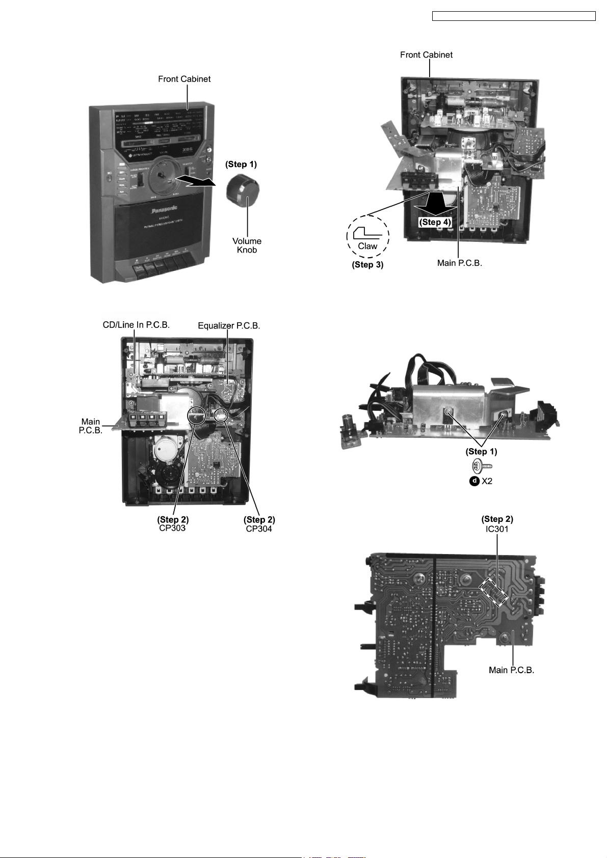
6.7.3. Disassembly Main P.C.B.
Step 1: Remove volume knob.
RX-CS45GC / RX-CS45GU / RX-CS45GS / RX-CS45GS1
Step 3: Release the claw.
Step 4: Remove the Main P.C.B. as arrow shown.
Step 2: Disconnect the connectors (CP303 and CP304).
· Follow (Step 1) of item 6.7.1.
· Follow (Step 1) of item 6.7.2
6.7.3.1. Replacement of Power IC
· Follow the (Step 1 - Step 4) of item 6.7.3.
Step 1: Remove 2 screws.
Step 2: Unsolder all the pins for solder side of Main P.C.B.
13
 Loading...