

Panasonic RTM100 Operating Instructions
Instruction Manual
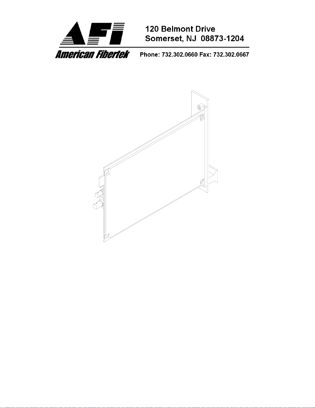
RTM-100
Video Transmitter
© Copyright 2003, American Fibertek, Inc. 0715JD

INSTALLATION AND OPERATION INSTRUCTIONS
INTRODUCTION
Thank you for purchasing your American Fibertek RTM-100 multimode video transmitter.
Please take a few minutes to read these installation instructions in order to obtain the
maximum performance from this product.
FUNCTIONAL DESCRIPTION
The RTM-100 operates as half of a transmitter / receiver pair for the transmission of
baseband NTSC, PAL, RS170, or RS343 video signals over a single multimode fiber
optic cable. It is designed to operate with the MRM-100, RRM-100, or RRM-30 video
receiver. The RRM-30 contains the electronics and optics of three RRM-100 units
mounted on one printed circuit board to save space and reduce cost.
The RTM-100 converts a single video input into a single FM modulated optical output
using an 850 nm wavelength source. The M100 Series product is designed to operate
over an optical loss budget range of 0 to 12 dB with a maximum distance of up to 2.5
km. The RTM-100 operates on 50 um or 62.5 um multimode fiber. Refer to the data
sheets for detailed performance specifications.
This unit is designed for rack mounting in any of the three American Fibertek subracks
available. The subrack model numbers are SR-20/1, SR-20R/1, and SR-20/2. Slide in
rack mounting and a LED indicator provide for easy installation and monitoring of video
and power.
The RTM-100 is designed for rack mounting only. For a modular stand alone version
please see the MTM-100.
INSTALLATION
THE INSTALLATION OF THIS UNIT SHOULD BE MADE BY A QUALIFIED SERVICE
PERSON(S) AND MUST CONFORM TO ALL LOCAL CODES.
The unit slides into any open slot in the SR-20 subrack. Use a small screwdriver to push
and lock the two ¼ turn fasteners into place. Please note that when installing this card in
the position directly next to the power supply in the SR-20 subrack, it may be necessary
to make the signal connections at the rear of the card before fully seating the card into
its slot.
POWER SOURCE
Power to the unit is supplied by the subrack. Please refer to the SR-20 and PSR
instructions for further details.
POWER CONNECTION
Power is supplied to the unit via a four finger backplane connector. The RTM-100 can be
inserted into the subrack or removed from the subrack with power applied to the
backplane.
2
 Loading...