

Panasonic PV-DV400, PV-DV200 Owner’s Manual

Digital Palmcorde ,® Panasonic o
PalmSight TM
Digital Video Camcorder
t_erating Instructions
odelsNo.PV-DV200
PV-DV400
(PV-DV400 shown)
IPV-DV200I1-_ PV-DV400_J
Before attempting to connect, operate or adjust this product, please read these
instructions thoroughly.
Spanish Quick Use Guide is included.
Gufa para r_ipida consulta en espa_ol estd incluida.
i _,] u_. _.-!.-_l.-t_.lm[_-.m=_.nill lt:[0IolPJili n "./_,1_r_,Yl'PJ_
LSQT021ZA
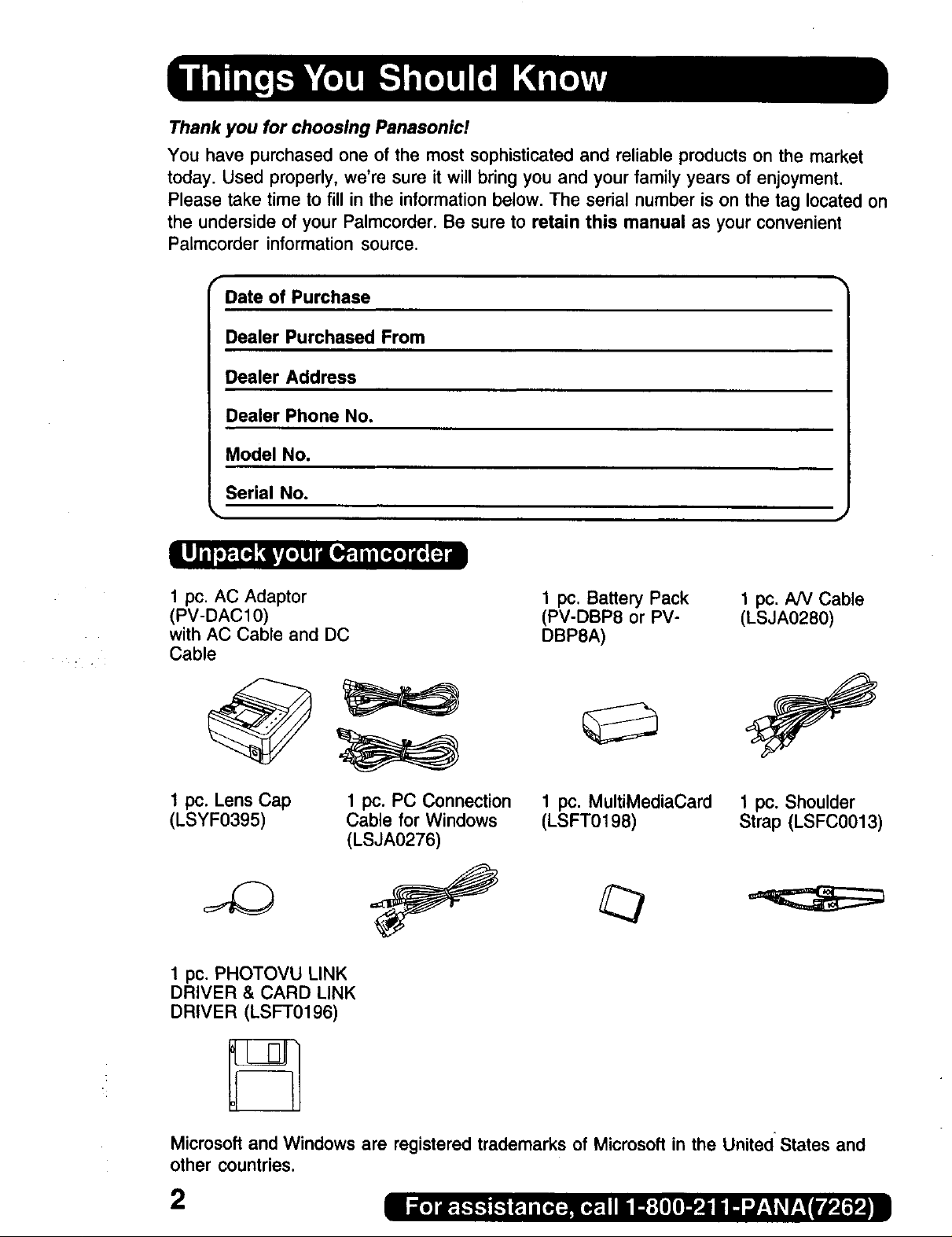
Thank you for choosing Panasonic!
You have purchased one of the most sophisticated and reliable products on the market
today. Used properly, we're sure it will bring you and your family years of enjoyment.
Please take time to fill in the information below. The serial number is on the tag located on
the underside of your Palmcorder. Be sure to retain this manual as your convenient
Palmcorder information source.
r
Date of Purchase
Dealer Purchased From
Dealer Address
Dealer Phone No.
Model No.
Serial No.
1 pc. AC Adaptor
(PV-DACl0)
with AC Cable and DC
Cable
1 pc. Lens Cap
(LSYF0395)
1 pc. PHOTOVU LINK
DRIVER & CARD LINK
DRIVER (LSFT0196)
1 pc. PC Connection
Cable for Windows
(LSJA0276)
1 pc. Battery Pack
(PV-DBP8 or PV-
DBP8A)
1 pc. MultiMediaCard
(LSFT0198)
1 pc. NV Cable
(LSJA0280)
1 pc. Shoulder
Strap (LSFC0013)
Microsoft and Windows are registered trademarks of Microsoft in the United States and
other countries.
2
WARNING: TO PREVENT FIRE OR SHOCK HAZARD,
DO NOT EXPOSE THIS EQUIPMENT TO RAIN OR MOISTURE.
Your ,,°,i}_- Palmcorder is designed to record and play back in Standard Play (SP) mode
and Long (LP) mode.
It is recommended that only cassette tapes that have been tested and inspected for use in
VCR machines with the "_°'1_"mark be used.
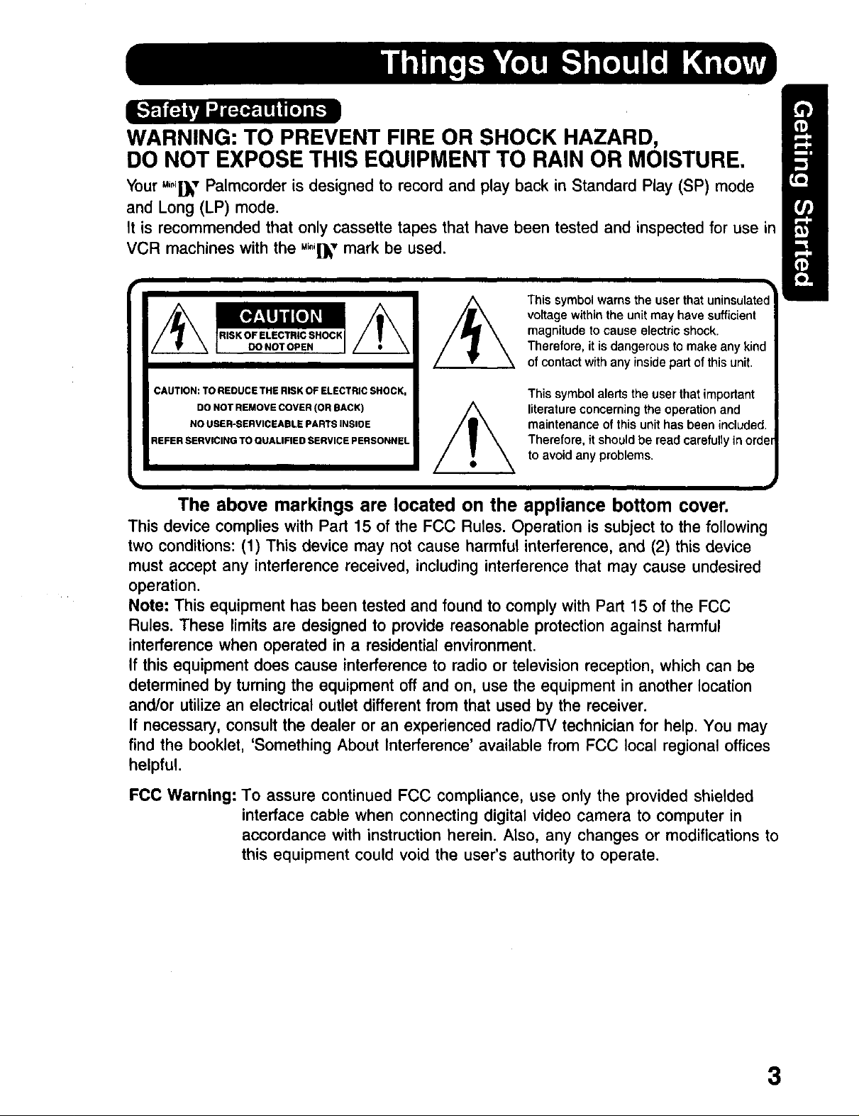
This symbol warns the user that uninsulated
voltage withinthe unit may have sufficient
magnitude to cause electric shock.
Therefore, it is dangerous tomake any kind
of contactwithany insidepart of this unit.
CAUTION: TO REDUCE THE RISK OF ELECTRIC SHOCK,
DO NOT REMOVE COVER (OR BACK)
NO USER-SERVICEABLE PARTS INSIDE
REFER SERVICING TO QUALIFIED SERVICE PERSONNEL
This symbol alerts the user that important
literature concerning the operation and
maintenance of this unit has been included.
Therefore, it should be read carefully in orde_
to avoid any problems.
The above markings are located on the appliance bottom cover.
This device complies with Part 15 of the FCC Rules, Operation is subject to the following
two conditions: (1) This device may not cause harmful interference, and (2) this device
must accept any interference received, including interference that may cause undesired
operation.
Note: This equipment has been tested and found to comply with Part 15 of the FCC
Rules. These limits are designed to provide reasonable protection against harmful
interference when operated in a residential environment.
If this equipment does cause interference to radio or television reception, which can be
determined by turning the equipment off and on, use the equipment in another location
and/or utilize an electrical outlet different from that used by the receiver.
If necessary, consult the dealer or an experienced radio/TV technician for help. You may
find the booklet, 'Something About Interference' available from FCC local regional offices
helpful.
FCC Warning: To assure continued FCC compliance, use only the provided shielded
interface cable when connecting digital video camera to computer in
accordance with instruction herein. Also, any changes or modifications to
this equipment could void the user's authority to operate.
3
1. Read Instructions -- All the safety and operating
instructions shouldbe read before the unit is
operated.
2. Retain Instructions -- The safety and operating
instructions should be retained for future reference.
3. Heed Warnings -- All warnings on the unit andin the
operating instructions should be adhered to.
4. Follow Instructions -- All operating and maintenance
instructions should be followed.
5. Cleaning -- Unplug this video unit from the wall outlet
before cleaning. Do not use liquid or aerosol
cleaners. Use a dry cloth forcleaning.
6. Attachments-- Do not use attachments not
recommended by the video product manufacturer as
they may be hazardous.
7. Water and Moisture -- Do not use this video unit near
water -- for example near abath tub, wash bowl,
kitchen sink, or laundrytub, in a wet basement, or
near a swimming pool, and the like.
8. Accessories -- Do not place thisvideo unit on an
unstable cart, stand, tripod, bracket, or table. The
video unit may fall, causing serious injury to a child or
adult, and serious damage to the unit. Use only with
a cart, stand, tripod, bracket, or table recommended
bythe manufacturer, or sold with thevideo unit. Any
mounting of the unit should follow the manufacturer's
instructions and should use a
recommended by the
manufacturer. An appliance and
cart combination should be moved
with care. Quick stops, excessive
mounting accessory
force, and uneven surfaces may
cause the appliance and cart
combination to overturn.
9. Ventilation -- Slots and openings in the cabinet are
provided for ventilation and to ensure reliable
operation of the video unit and to protectit from
overheating. These openings must not be blccked or
covered. Never place the video unit on a bed, sofa,
rug, or othersimilar surface, or near or over a radiator
or heat register. This video unit should notbe placed
in a built-in installation such as a bookcase or rack
unless proper ventilation is provided or the
manufacturer's instructions have been adhered to.
10. Power Sources -- This video unit should be operated
only from the type of power source indicated on the
marking label.If you are not sure of the type of power
supply to your home, consult your appliance dealer
or local power company. For video units intended to
be operated from battery power, or other sources,
referto the operating instructions.
1t. Grounding or Polarization -- This video unitmaybe
equipped with either a polarized 2-wire AC
(Alternating Current) line plug (a plug having one
blade wider thanthe other) or 3-wire grounding type
plug, a plug having athird (grounding) pin.
The 2-wire polarized plug will fit intothe power outlet
only one way. This is a safety feature. Ifyou are
unable to insert the plug fullyinto the outlet, try
reversing the plug.Ifthe plug stillfails tofit, contact
your electrician to replace your obsolete outlet. Do
not defeat the safety purpose of the polarized plug.
The 3-wiregrounding type plug willfit into a
grounding type power outlet. This is a safetyfeature.
Ifyou are unable to insert the plug into the outlet,
contact your electrician to replace your obsolete
outlet. Do not defeat the safety purpose of the
grounding type plug.
t2. Power-Cord Protection -- Power-supply cords
should be routed so that they are not likely to be
walked on or pinched by items placed upon or
against them, paying particularattention to cords of
plugs, convenience receptacles, and the point
where they exit from the unit.
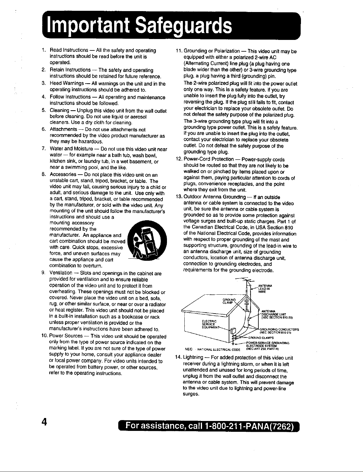
13. Outdoor Antenna Grounding-- If an outside
antenna or cable system is connected to the video
unit, be sure the antenna or cable system is
grounded so as to provide some protectionagainst
voltage surges and built-up static charges. Part 1 of
the Canadian Electrical Code, in USA Section 810
of the National Electrical Code, provides information
with respect to proper grounding of the mast and
supporting structure, grounding of the lead-in wire to
an antenna discharge unit, size of grounding
conductors, location of antenna discharge unit,
connection to grounding electrodes, and
requirements forthe grounding electrode.
_.- ANTENNA
LEAD IN
WIRE
GROUND E
CLAMP [
DISCHA_GE UNIT
NTEN
NEC NATIONAL ELECTRICAL CODE (NEC ART 250 PART HI
14. Lightning -- Foradded protectionof this video unit
receiver during a lightning storm, or when it is left
unattended and unused for long periods of time,
unplug it from the wall outlet anddisconnect the
antenna or cable system. This willprevent damage
to thevideo unit due to lightning and power-line
surges.
(NECSECTION8!0-20)
GROUN_NG CONDUCTORS
EC SECTION BI0.2_)
GROUND Ct_Mp$
_ER S_RVtCE GROUNDING
ELECTR_E SYSTEM
4
15. Power Lines -- Anoutside antenna system should
not be located in the vicinity of overhead power lines
or other electric light orpower circuits, or where it can
fall into such power lines orcircuits. When installing
an outside antenna system, extreme care should be
taken to keep from touching such power lines or
circuits as contact with them might be fatal.
16.Overloading -- Do net overload wall outlets and
extension cords as this can result in a risk of fire or
electric shock.
17. Objectsand Liquids -- Never push objects of any
kind into this video unit through openings as they
may touch dangerous voltage points or short out
parts that could result ina fire or electric shock.
Never spill liquid of any kind onto the video unit,
18. Servicing -- Do not attempt to service this video unit
yourself as opening or removing covers may expose
you to dangerous voltage or other hazards. Refer all
servicing to qualified service personnel,
t 9. Damage Requiring Service -- Unplug this video unit
from the wall outlet and refer servicing to qualified
service personnel under the following conditions:
a. When the power-supply cord or plug is damaged.
b. Ifany liquid has been spilled onto, or objects have
fallen into the video unit.
c. If the video unit has been exposed to rain or water.
d. Ifthe video unit does not operate normally by
following the operating instructions. Adjust only
those controls that are covered by the operating
instructions, as an improper adjustment of other
controls may result in damage and will often
require extensive work by a qualilied technician to
restore the video unit to its normal operation.
e, If the video unit has been dropped or the cabinet
has been damaged.
f. When the video unit exhibits a distinct change in
performance -- this indicates a need for service.
20. Replacement Parts -- When replacement parts are
required, be sure the service technician has used
replacement parts specified by the manufacturer or
have the same characteristics as the original part.
Unauthorized substitutions may result in fire, electric
shock or other hazards.
21. Safety Check-- Upon completion of any service or
repairs to this video unit, ask the service technician to
perform safety checks to determine that the video
unit is in safe operating order.
USE & LOCATION
• TO AVOID SHOCK HAZARD ... Your Camcorder and power supplyshould not be exposed to rain or moisture, Do
not connect the power supplyor operate your Camcorder if it gets wet. Your Camcorder has been designed for
outdoor use, however it is not designed tosustain direct exposure to water, rain, sleet, snow, sand, dust, or a direct
splashing from a pool or even a cup of coffee. This action could permanently damage the internal parts of your
Camcorder. Do not attempt to disassemble this unit, There are no user serviceable parts inside. Unplug your
Camcorder from the power supply before cleaning.
• DO NOT AIM YOUR CAMCORDER AT THE SUN OR OTHER BRIGHT OBJECTS
• DO NOT LEAVE THE PALMCORDER WITH THE EVF AIMED DIRECTLY AT THE SUN AS THIS MAY CAUSE
DAMAGE TO THE INTERNAL PARTS OF THE EVF
• DO NOT EXPOSE YOUR CAMCORDER TO EXTENDED HIGH TEMPERATURE ... Such as, in directsunlight,
insidea closed ear, nextto a heater, etc... Thisactioncouldpermanentlydamagethe internalpartsof your
Camcorder.
• AVOID SUDDEN CHANGES IN TEMPERATURE ... Ifthe unit is suddenly movedfrom a cold place to a warm
place,moisturemay formon the tape and insidethe unit.
• DO NOT LEAVE YOUR CAMCORDER OR THE POWER SUPPLY TURNED ON WHEN NOT IN USE.
• STORAGE OF YOUR CAMCORDER ... Storeand handleyour Camcorderina manner thatwillnot subjectitto
unnecessarymovement (avoid shakingand striking).YourCamcordercontainsa sensitivepick-updevice which
couldbe damaged by improperhandlingor storage.
CARE
• TO CLEAN YOUR CAMCORDER ... Do not use strong or abrasive detergents when cleaning yourCamcorder
body.
• TO PROTECT THE LENS ... Do not touchthe surfaceof the lens with yourhand. Use a commercialcamcorder
lenssolutionand lenspaper whencleaningthe lens. Impropercleaningcan scratchthe lenscoating.
• TO PROTECT THE FINISH OF YOUR CAMCORDER ... Before handlingyourCamcorder,make sureyour hands
andface are free from any chemicalproducts,suchas suntanlotion, as it may damage the finish.
5

Things You Should Know .................................................................................................... 2
Important Safeguards ......................................................................................................... 4
Precautions ......................................................................................................................... 5
Quick Guide ......................................................................................................................... 8
Supplying Power ............................................................................................................... 11
Cassette Information ......................................................................................................... 14
Color Enhancement Light (Optional) ................................................................................ 16
Attaching the Shoulder Strap ............................................................................................ 17
Setting the Clock ............................................................................................................... 19
Using the Palmdorder Menu ............................................................................................. 20
MENU OSD ....................................................................................................................... 21
Electronic Viewfinder/LCD Monitor Indications ................................................................ 26
Camera Recording ............................................................................................................ 30
Remote Control (Optional) ................................................................................................ 33
Playback Your Recordings ................................................................................................ 35
Card PhotoShot ................................................................................................................. 41
Recording images From a Tape ........................................................................................ 42
Playback Still Images ........................................................................................................ 43
Delete Specific Image Pages ........................................................................................... 45
Delete All Image Pages .................................................................................................... 46
Format the MultiMediaCard .............................................................................................. 47
Photo Title .......................................................................................................................... 48
Dual Digital Electronic Image Stabilization System (D.E.I.S.) ......................................... 50
Zoom .................................................................................................................................. 51
Digital PhotoShot .............................................................................................................. 52
Index Search ..................................................................................................................... 52
White Balance ................................................................................................................... 53
Recording Still Pictures .................................................................................................... 53
IR FILTER .......................................................................................................................... 53
Program AE ....................................................................................................................... 54
Digital Functions ............................................................................................................... 55
Focus ................................................................................................................................. 56
Audio/Video Fade In/Out ................................................................................................... 57
Backlight ............................................................................................................................ 57
High Speed Shutter ........................................................................................................... 58
Audio Dubbing using the External or Built-in Microphone ............................................... 59
Memory-Stop Editing ........................................................................................................ 60
Copying your Tapes to S-VHS or VHS Cassette .............................................................. 61
Copying from Digital Equipment (dubbing) ...................................................................... 62
PC Connection with DV Interface Cable (IEEE 1394) ..................................................... 63
PC Connection .................................................................................................................. 64
Software Installation (Windows 95/98) ............................................................................. 65
CARD LINK ....................................................................................................................... 66
PHOTOVU LINK ................................................................................................................ 69
Printer Connection ............................................................................................................ 71
6

Palmcorder Accessory System ........................................................................................ 72
Palmcorder Accessory Order Form .................................................................................. 73
Notes On Operations ........................................................................................................ 74
Specifications .................................................................................................................... 76
Before Requesting Service ............................................................................................... 77
Request for Service Notice ............................................................................................... 79
Index of Controls ............................................................................................................... 80
Warranty ............................................................................................................................ 85
Spanish Quick Use Guide/Guia Para Uso Rapido .......................................................... 87
Index .................................................................................................................................. 90
This operating Instruction book is designed for use with models PV-DV200 and PV-DV400.
The PV-DV400 is the model used for illustrative purposes.
Features may vary, so please read carefully.
Differences between models
Model Number PV-DV200 PV-DV400
LCD Monitor 63.5 mm (2.5 inch) 76.2 mm (3.0 inch)
Liquid Crystal Display Liquid Crystal Display
Viewfinder Black and White Color
IR FILTER
Switch
WIND-CUT No Yes
No Yes
7
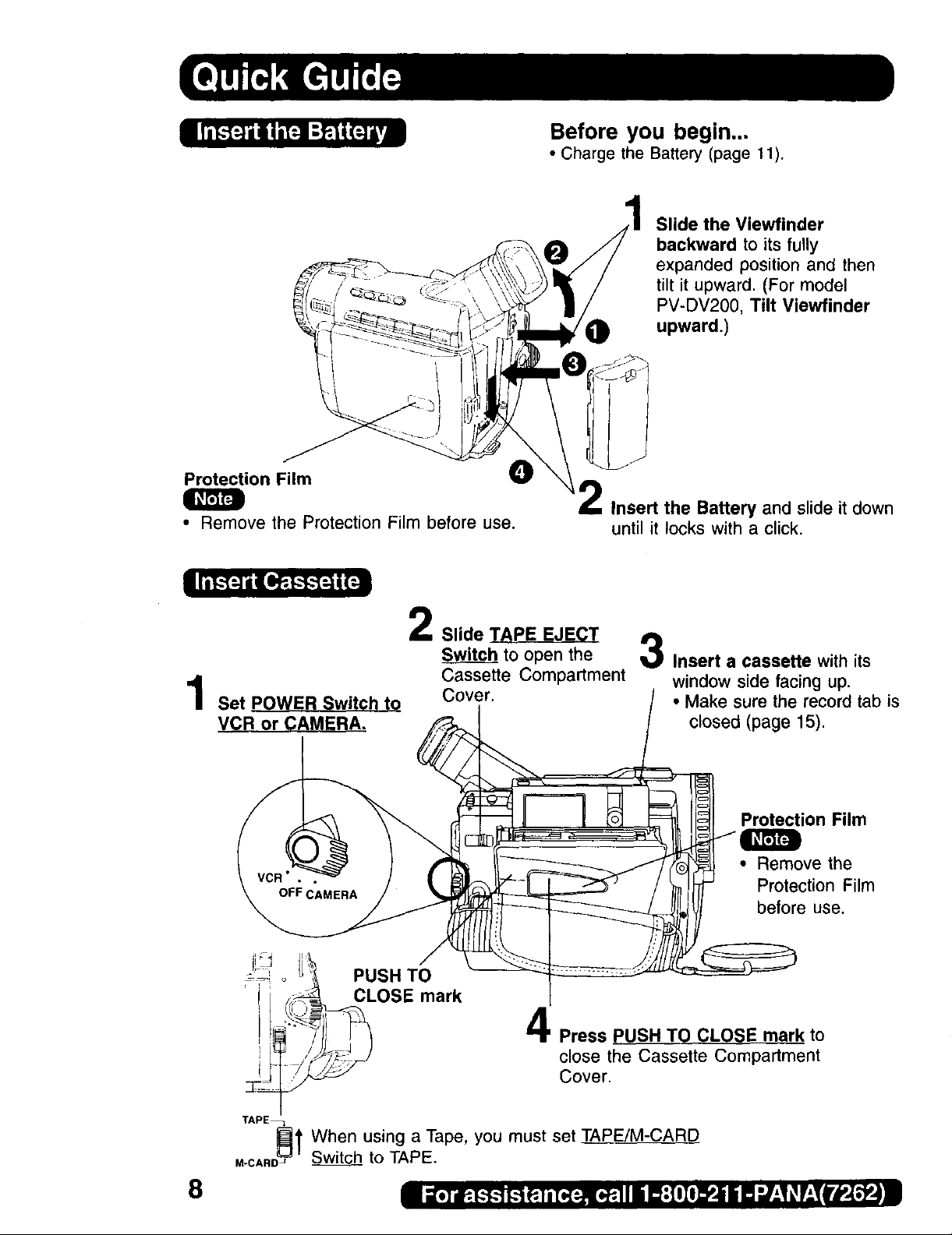
Before you begin...
• Charge the Battery (page 11).
Slide the Viewfinder
backward to its fully
expanded position and then
tilt it upward. (For model
PV-DV200, Tilt Viewfinder
upward.)
Protection Film _)
• Remove the Protection Film before use.
L
Slide TAPE EJECT
Switc_.__bhto open the
Cassette Compartment
Set POWER Switch to Cover.
VCR or CAMERA.
Insert the Battery and slide it down
until it locks with a click.
3
Insert a cassette with its
window side facing up.
• Make sure the record tab is
closed (page 15)
Protection Film
• Remove the
Protection Film
before use.
8
PUSH TO
CLOSE mark
Press PUSH TO CLOSE mark to
close the Cassette Compartment
Cover.
TAPE_
_1 When using a Tape, you must set TAPE!M-CARD
,-CARDJ Switch_to TAPE.
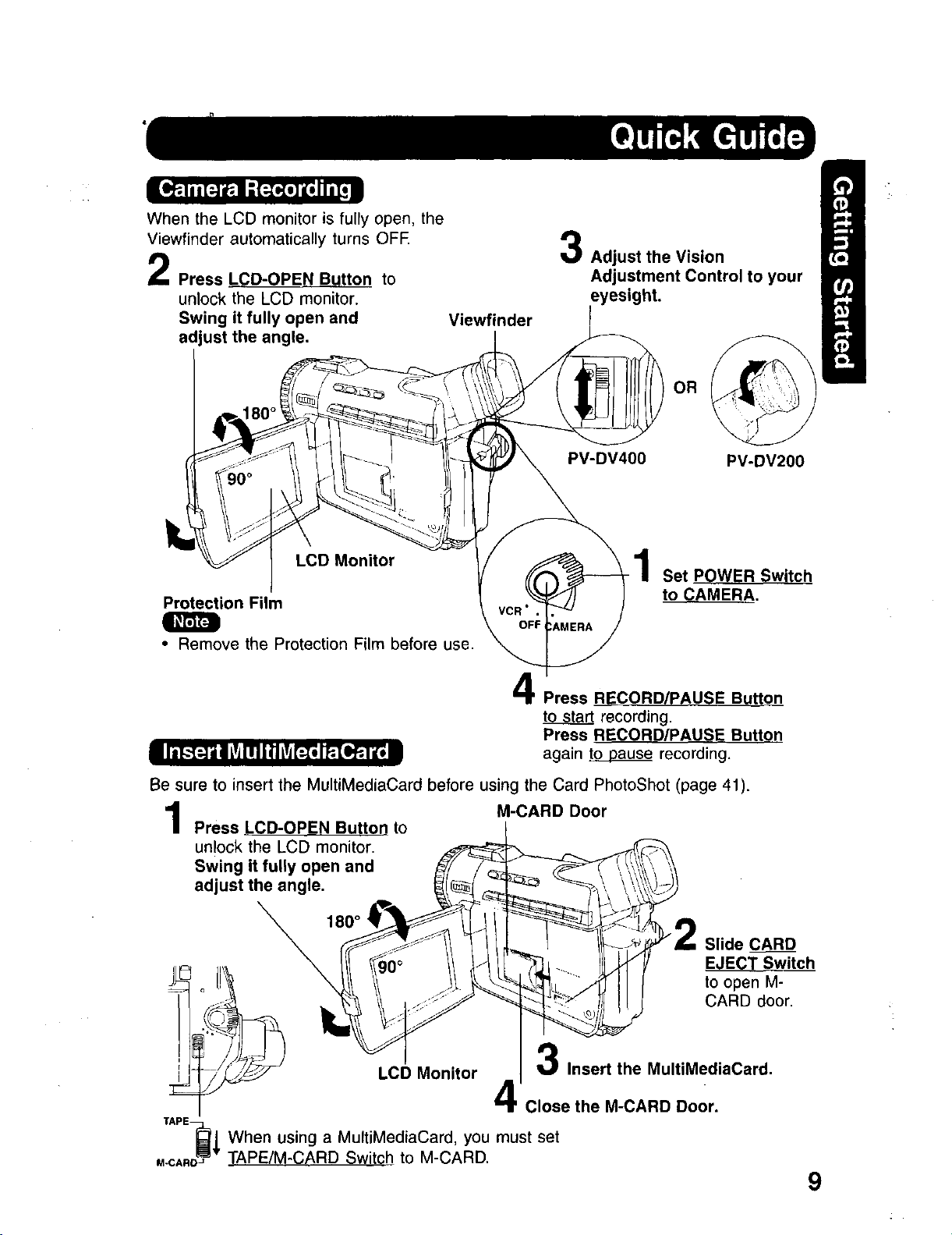
When the LCD monitor is fully open, the
Viewfinder automatically turns OFE
Press LCD-OPEN Button to
unlock the LCD monitor.
Swing it fully open and
adjust the angle.
LCD Monitor
Protection Film
• Remove the Protection Film before use.
Viewfinder
3
Adjust the Vision
Adjustment Control to your
• ht.
PV-DV400 PV-DV200
Set POWER Switch
to CAMERA•
Press R!_CORD/PAUSE Buttonn
to start recording.
Press RECORD/PAUSE Button
again toQpause recording.
Be sure to insert the MultiMediaCard before using the Card PhotoShot (page 41).
Press LCD-OPEN Button to
unlock the LCD monitor.
Swing it fully open and
adjust the angle.
_80 o1
coonor
XAPE_j When using a MultiMediaCard, you must
M-CAnD_wTAPE/M-CARD Sw tch to M-CARD.
M-CARD Door
Slide CARD
EJECT Switch
to open M-
CARD door.
Insert the MultiMediaCard.
Close the M-CARD Door.
set
9
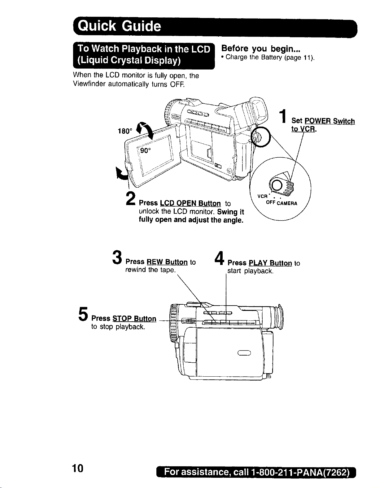
When the LCD monitor is fully open, the
Viewfinder automatically turns OFE
180 °
Press LCD OPEN Button to
unlock the LCD monitor. Swing it
fully open and adjust the angle.
BefOre you begin...
• Charge the Battery (page 11).
Set POWER Switch
to
3 4
Press REW Button to
rewind the tape.
5 Press STOP Button I _
to stop playback.
Press PLAY Button to
sta_p_.
L_q
k
10

Connect and plug in the Cable as
shown.
• POWER Lamp will light.
,/" .
POWER
Lamp _!'
CHARGE
Lamps
50 80
• The three Charge Lamps "50%", "80%" and "100%" flash and then remain lit one after
another to indicate how much the Battery has been charged. When all three lamps are
lit, charging is finished.
• The Charge Lamps give a good approximate indication of the charging condition under
normal ambient temperature. However, when charging at high or low temperature, the
charge lamps may differ considerably from the actual charging condition.
2
Attach the battery as shown to
charge.
• Charge lamps on the AC Adaptor will
flash and then turn solid red to
indicate current charge level. When
all 3 lamps are constantly on, the
battery is fully charged. (approx. 1
hour) Expect approx. 1 hour 15
minutes of operation when fully
charged (EVF usage).
3
Remove the Battery.
Slide the Battery out and then lift up.
Battery Charging
Confirmation Marker
(PV-DBP8 only)
Battery Charging Confirmation Marker
Use this marker as a reminder to yourself
when the battery is fully charged or in need
of a charge. This marker performs no
function and is for your reference only.
• The Battery is no longer serviceable if
the operation time is very short, even
after a sufficient charge.
Q
• PV-DBP8A has no marker.
11
O
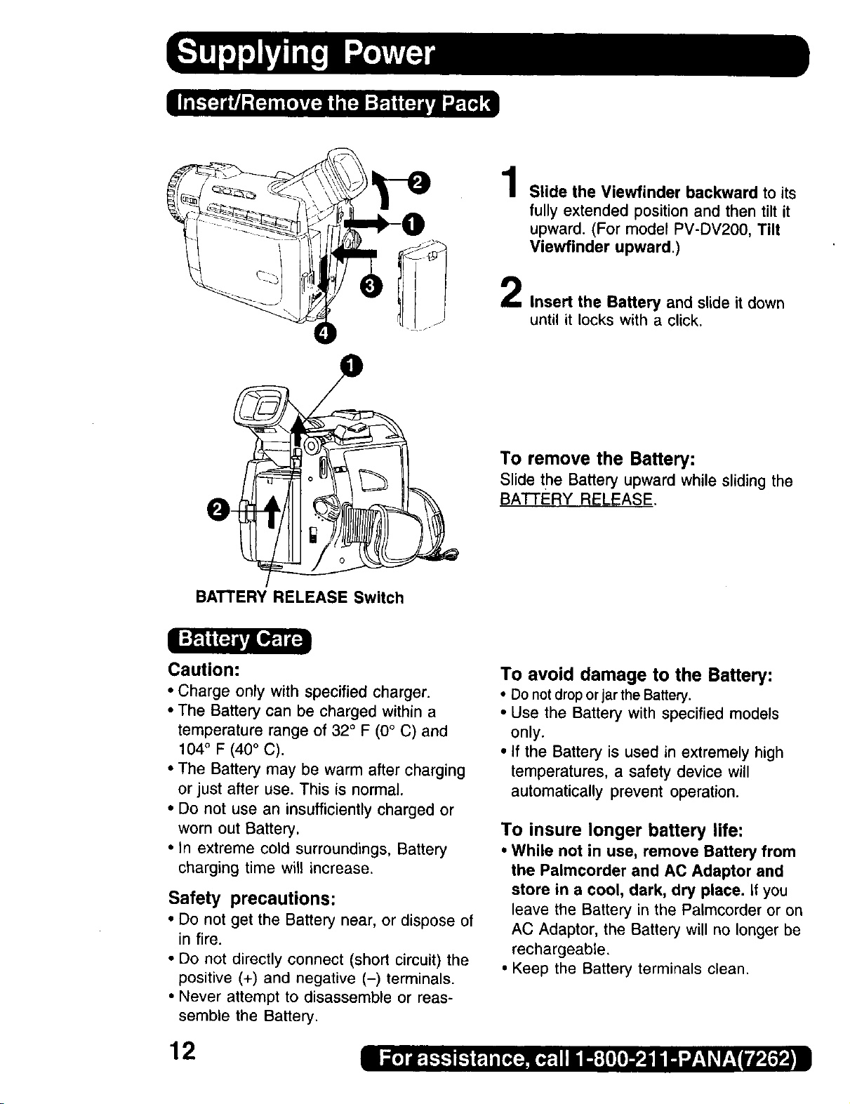
1
Slide the Viewfinder backward to its
fully extended position and then tilt it
upward. (For model PV-DV200, Tilt
Viewfinder upward.)
2
Insert the Battery and slide it down
until it locks with a click.
To remove the Battery:
Slidethe Batteryupwardwhile slidingthe
BATI'ERY RELEASE,
BATTERY RELEASE Switch
Caution:
• Charge only with specified charger.
• The Battery can be charged within a
temperature range of 32 ° F (0° C) and
104° F (40° C).
• The Battery may be warm after charging
or just after use. This is normal.
• Do not use an insufficiently charged or
worn out Battery.
• In extreme cold surroundings, Battery
charging time will increase.
Safety precautions:
• Do not get the Battery near, or dispose of
in fire.
• Do not directly connect (short circuit) the
positive (+) and negative (-) terminals.
• Never attempt to disassemble or reas-
semble the Battery.
To avoid damage to the Battery:
• Do notdroporjarthe Battery.
• Use the Battery with specified models
only.
• If the Battery is used in extremely high
temperatures, a safety device will
automatically prevent operation.
To insure longer battery life:
• While not in use, remove Battery from
the Palmcorder and AC Adaptor and
store in a cool, dark, dry place, if you
leave the Battery in the Palmcorder or on
AC Adaptor, the Battery will no longer be
rechargeable,
• Keep the Battery terminals clean.
12

BA'I-rERY RELEASE Switch
Slide the Battery upward while sliding
the BATTERY RELEASE to remove
the Battery (page 12).
Insert the DC Cable into the DC IN
Terminal.
Connect the other end of the DC
Cable to the AC Adaptor as shown.
Plug in the AC Adaptor.
• The POWER Lamp of the AC Adaptor
lights up.
OC IN Terminal
O
(Supplied)
0
DC IN Terminal
• When not in use, unplug the AC Adaptor
O
POWER
Lamp
from the AC outlet. (AC Adaptor
consumes 1W of electric power when
plugged into an AC outlet even when not
in use.)
13

Before you begin...
• Connect the Palmcorder to a power
source (pages 12, 13).
TAPE EJECT 1Slide TAPE EJECT to open the
Switch Cassette Compartment Cover.
2 Insert a cassette with its window side
facing up.
PUSH TO --
CLOSE mark _,_ Press PUSH TO CLOSE mark to
close the Cassette Compartment
Cover.
Cassette Compartment
Cover
• If the Palmcorder is connected to a power
source, the cassette can be inserted and
ejected without turning the Palmcorder
on.
Slide TAPE EJECT to open the
Cassette Compartment Cover.
Pull the cassette tape straight out.
Note:
• If hand strap is tight it may prevent Cassette Compartment Cover
from fully opening for tape insert or eject. Loosen hand strap if
necessary.
• When inserting the cassette, make sure it faces in the right direction
and then push in completely.
i
Hint for recording position when
inserting Cassette
• When you insert a cassette that is
partially recorded, use the Edit Search
Function to search for the positionfrom
which you want to record again,
Especially when you want to record again
on a cassette that is already fully
recorded, be sure to first locate the
position where you want to add the new
recording, before starting to record,
14
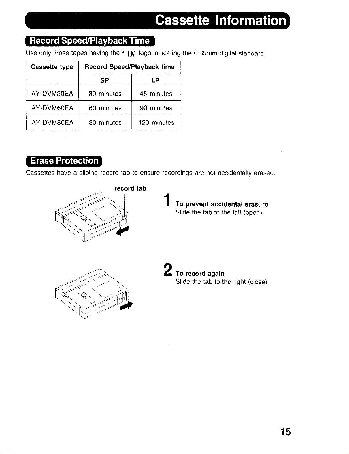
Use only those tapes having the "_'"'l_" logo indicating the 6.35mm digital standard.
Cassette type Record Speed/Playback time
SP LP
AY-DVM30EA 30 minutes 45 minutes
AY-DVM60EA 60 minutes 90 minutes
AY-DVM80EA 80 minutes 120 minutes
Cassettes have a sliding record tab to ensure recordings are not accidentally erased.
record tab
To prevent accidental erasure
Slide the tab to the left (open).
To record again
Slide the tab to the right (close).
15

To brighten the natural colors in a scene.
Built-in Light Mount
Before you begin...
• Connect the Palmcorder to a power sourc
(pages 12, 13).
• Set POWER to CAMERA.
Slide L ght nto the Built-in Light
Mount.
Be sure it locks into place.
Press LIGHT ON.
Press IG_ again to OFF.
LIGHT RELEASE
Button
• Using the light will reduce battery operating time.
• If using the enhancement Light for an extended period of time, be sure to provide
ventilation when using it in a hot environment.
• Be sure LIGHT is set to OFF when not in use.
• Do not attempt to lift or carry the Palmcorder by holding the Enhancement Light.
• if light bulb needs to be replaced, take Light to your nearest authorized service center.
LIGHT Button
To remove the Light:
Press LIGHT RELEASE and slide the Li_
out of the mount.
Caution:
This light becomes hot during operation.
Make sure nothing covers the Light durin,
operation.
16
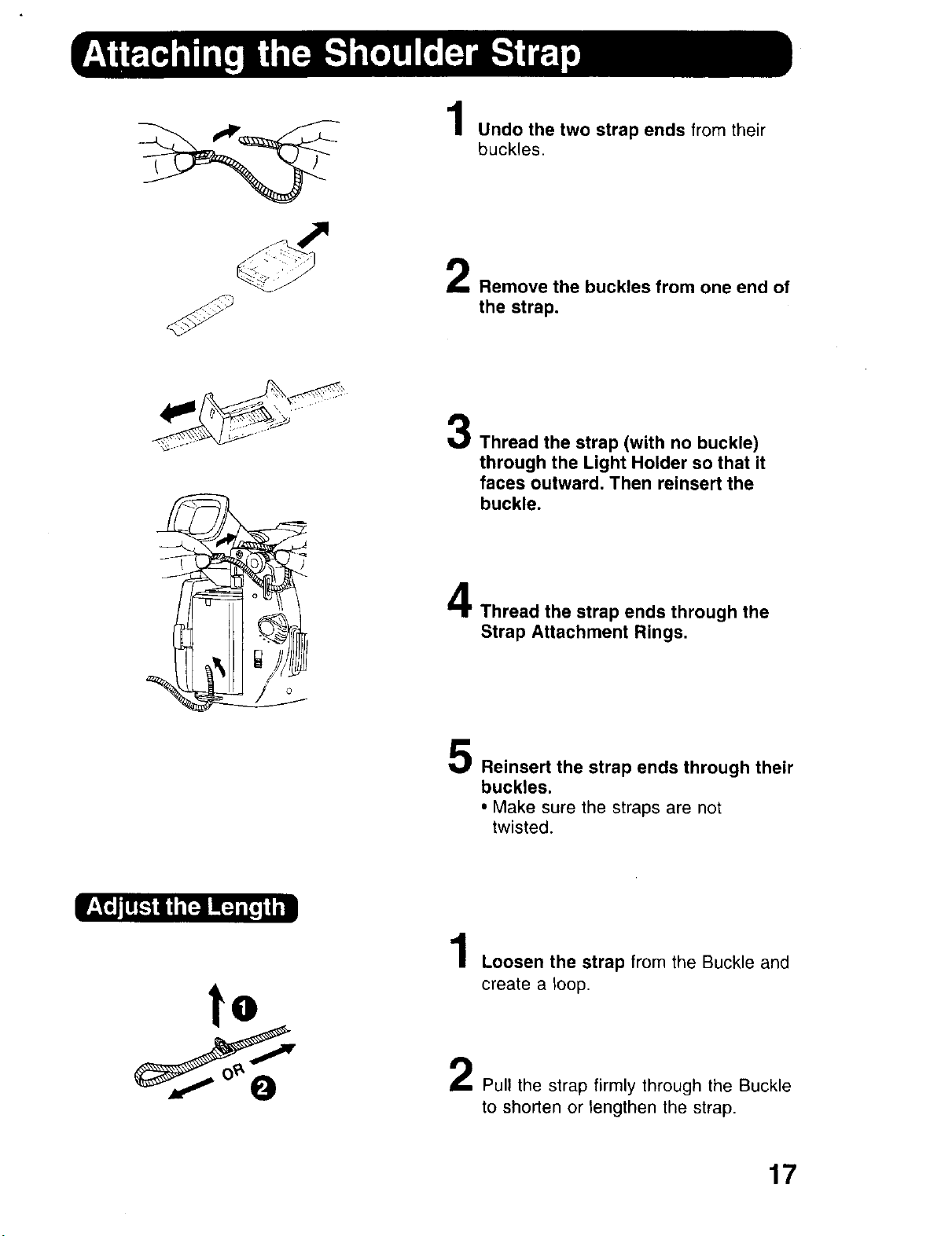
Undo the two strap ends from their
buckles.
Removethe buckles from one end of
the strap.
3
Thread the strap (with no buckle)
through the Light Holder so that it
faces outward. Then reinsert the
buckle.
to
4
Thread the strap ends through the
Strap Attachment Rings.
Reinsert the strap ends through their
buckles.
• Make sure the straps are not
twisted.
1
Loosen the strap from the Buckle and
create a loop.
Pull the strap firmly through the Buckle
to shorten or lengthen the strap.
17
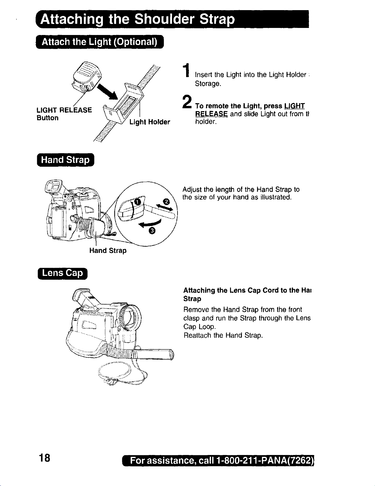
Storage,
LIGHT RELEASE 2 To remote the Light, press LI_
Button _ Light Holder
_\___ 1 Insert the Light into the Light Holder :
RELEASE and slide Light out from tt
Adjust the length of the Hand Strap to
the size of your hand as illustrated.
Hand Strap
18
Attaching the Lens Cap Cord to the Ha=
Strap
Remove the Hand Strap from the front
clasp and run the Strap through the Lens
Cap Loop.
Reattach the Hand Strap,

The date and time is calculated, including
leap year, up to DEC 31 2089.
Before you begin.,.
• Connect the Palmcorder to a power source
(pages 12, 13).
• Set POWER to CAMERA or VCR.
MENI
Button
-- EXAMPLE:
_'d=!r.,1=q
JOG KEY
:2000
rm_Tm_m]
Push
: JAN
Press MENU to display the Camera or
VCR mode menu screen (page 21).
CAMERA MENU VCR MENU
..W ]
2:REC MODE
4:SET-UP 5:DISPLA y SETTING
5:DISPLAY SETTJNG 6:LCD/EVF SETTING
6:LCOIEVF SETTING
7:pHOTOTITLE
*SELECT:ROTATE JOG KEY 'SELECT:ROTATE JOG KEY
3:REC MODE 4:PLAY MODE
*SET :PUSH JOG KEY 'SET :PUSH JOG KEY
*EXIT :PUSH MENU KEY 'EXIT :PUSH MENU KEY
2Rotate JOG KEY to selectl;_i_
_L_. and then press JOG KEY
to display the DISPLAY SETTING
menu screen.
• DISPLAY SETTING menu is
displayed.
Rotate JOG KEY to se ect_i_!_i_i_
[_:;_,,, , and then press JOG KEY to set
to ON (pages 22, 24).
•The DATE/TIME SETTING menu
appears.
Rotate
Vb_o]_il:
: FEB
• If you should pass the current year,
continue pressing down on the JOG KEY
until the year appears again.
• A built-in battery maintains clock
operation. If the Palmcorder is not
connected to a power source for a few
months, the built-in battery may discharge
and "CLOCK BATTERY" indication
appears (page 29).
Rotate JOG KEY to select the desired
numbers, then, press JOG KEY_down
to fix that portion and move to the next.
Adjust the shaded items for the year,
month, day, hour, and minute.
ol_llL=lfiJ]l_l_ El=lllllll_
[_ :2000
MONTH : OCT
DAY : 18
HOUR :SPM
MINUTE:I 0
SELECT:PUSH JOG KEY
• SET :ROTATE JOG KEY
• EXIT :PUSH MENU KEY
When time setting is completed, press
the MENU to start the clock.
19
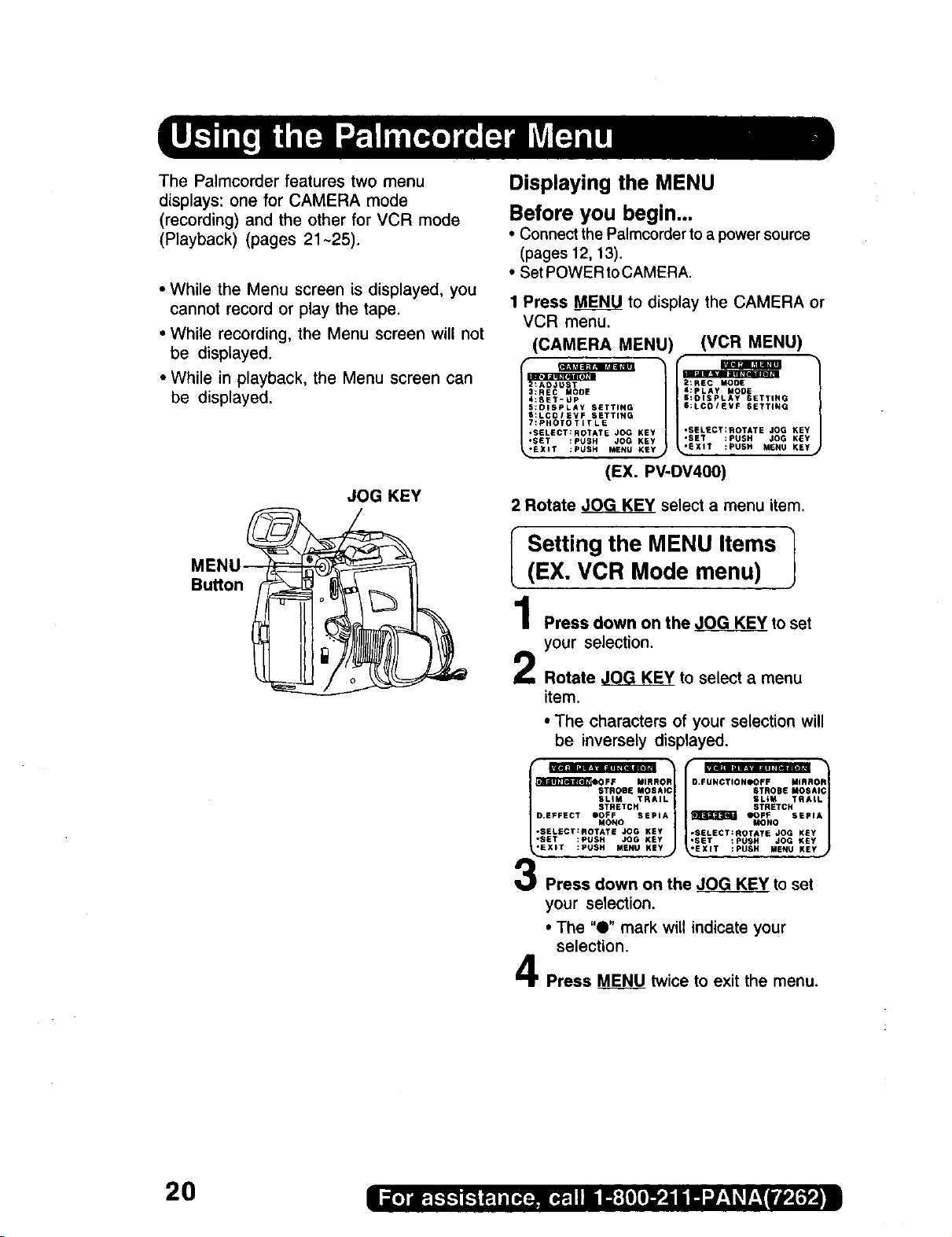
The Palmcorder features two menu
displays: one for CAMERA mode
(recording) and the other for VCR mode
(Playback) (pages 21-25).
• While the Menu screen is displayed, you
cannot record or play the tape.
• While recording, the Menu screen will not
be displayed.
• While in playback, the Menu screen can
be displayed.
JOG KEY
Displaying the MENU
Before you begin,..
• Connect the Palmcorder to a power source
(pages 12, t3).
• Set POWER to CAMERA.
1 Press MENU to display the CAMERA or
VCR menu.
(CAMERA MENU)
5:DISPLAY SETTING
S:LCOIEVF SETTING
7:PHOTOTITLE
•SELECT:ROTATE JOG KEY
:SET-UP
•SET :PUSH JOG KEY
EXIT :PUSH MENU KEY
(EX. PV-DV400)
2 Rotate _ select a menu item.
(VCR MENU)
4:PLAY MODE
S:OISPLAY SETTING
$:LCOIEVF SETTING
•SELeCT:ROTATE JOG KEY
•SET :PUSH JOG KEY
'EXIT :PUSH MENU KEY
MENU_
Button_
I Setting the MENU Items 1
(EX. VCR Mode menu)
1
Press down on the ,JOG KEY to set
your selection.
2
Rotate JOG KEY to select a menu
item.
• The characters of your selection will
be inversely displayed.
SLIM TRAIL
D EFFECT i)OFF SEPIA
*SELECT:SOTATE JOG KEY
,SET :PUSH JOG KSy
-EXIT :PUSH MENU KEY
STRETCH
MONO
STROBE MOSAI 1
t
Press down on the JOG KEY to set
your selection.
• The "0" mark will indicate your
selection.
Press MENU twice to exit the menu.
2O
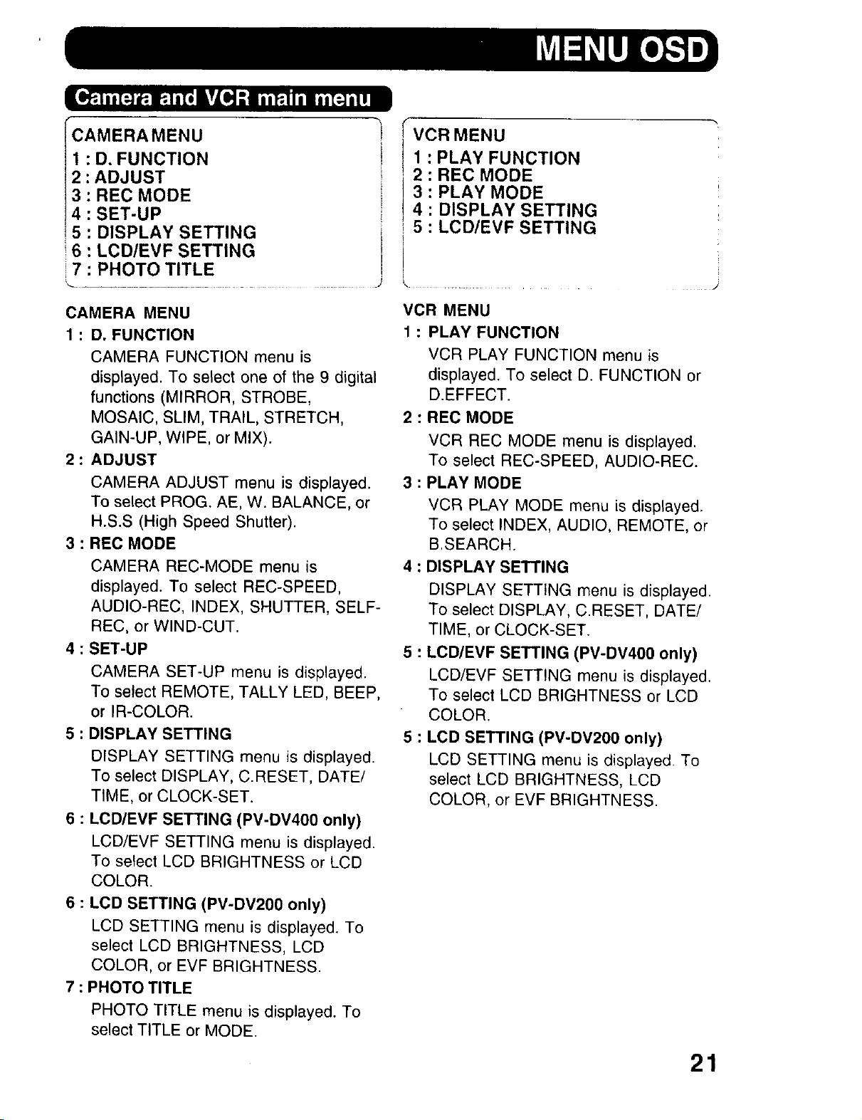
ICAMERAMENU
2: D, FUNCTION
: ADJUST
3 : REC MODE
4 : SET-UP
5 : DISPLAY SETTING
16 : LCD/EVF SETTING
i 7 : PHOTO TITLE
VCR MENU
1 : PLAY FUNCTION
2 : REC MODE
3 : PLAY MODE
4 : DISPLAY SETTING
i 5 : LCD/EVF SETTING
1
CAMERA MENU
1 : D. FUNCTION
CAMERA FUNCTION menu is
displayed. To select one of the 9 digital
functions (MIRROR, STROBE,
MOSAIC, SLIM, TRAIL, STRETCH,
GAIN-UP, WIPE, or MIX).
2 : ADJUST
CAMERA ADJUST menu is displayed.
To select PROG. AE, W. BALANCE, or
H.S.S (High Speed Shutter).
3 : REC MODE
CAMERA REC-MODE menu is
displayed. To select REC-SPEED,
AUDIO-REC, INDEX, SHUTTER, SELF-
REC, or WIND-CUT.
4 : SET-UP
CAMERA SET-UP menu is displayed.
To select REMOTE, TALLY LED, BEEP,
or IR-COLOR.
5 : DISPLAY SETTING
DISPLAY SETTING menu is displayed.
To select DISPLAY, C.RESET, DATE/
TIME, or CLOCK-SET.
6 : LCD/EVF SETTING (PV-DV400 only)
LCD/EVF SETTING menu is displayed.
To select LCD BRIGHTNESS or LCD
COLOR.
VCR MENU
1 : PLAY FUNCTION
VCR PLAY FUNCTION menu is
displayed. To select D. FUNCTION or
D.EFFECT.
2 : REC MODE
VCR REC MODE menu is displayed.
To select REC-SPEED, AUDIO-REC.
3 : PLAY MODE
VCR PLAY MODE menu is displayed.
To select INDEX, AUDIO, REMOTE, or
B.SEARCH.
4 : DISPLAY SETTING
DISPLAY SETTING menu is displayed.
To select DISPLAY, C.RESET, DATE/
TIME, or CLOCK-SET.
5 : LCD/EVF SETTING (PV-DV400 only)
LCD/EVF SETTING menu is displayed.
To select LCD BRIGHTNESS or LCD
COLOR.
5 : LCD SETTING (PV-DV200 only)
LCD SETTING menu is displayed. To
select LCD BRIGHTNESS, LCD
COLOR, or EVF BRIGHTNESS.
6 : LCD SETTING (PV-DV200 only)
LCD SETTING menu is displayed. To
select LCD BRIGHTNESS, LCD
COLOR, or EVF BRIGHTNESS.
7 : PHOTO TITLE
PHOTO TITLE menu is displayed. To
select TITLE or MODE.
21
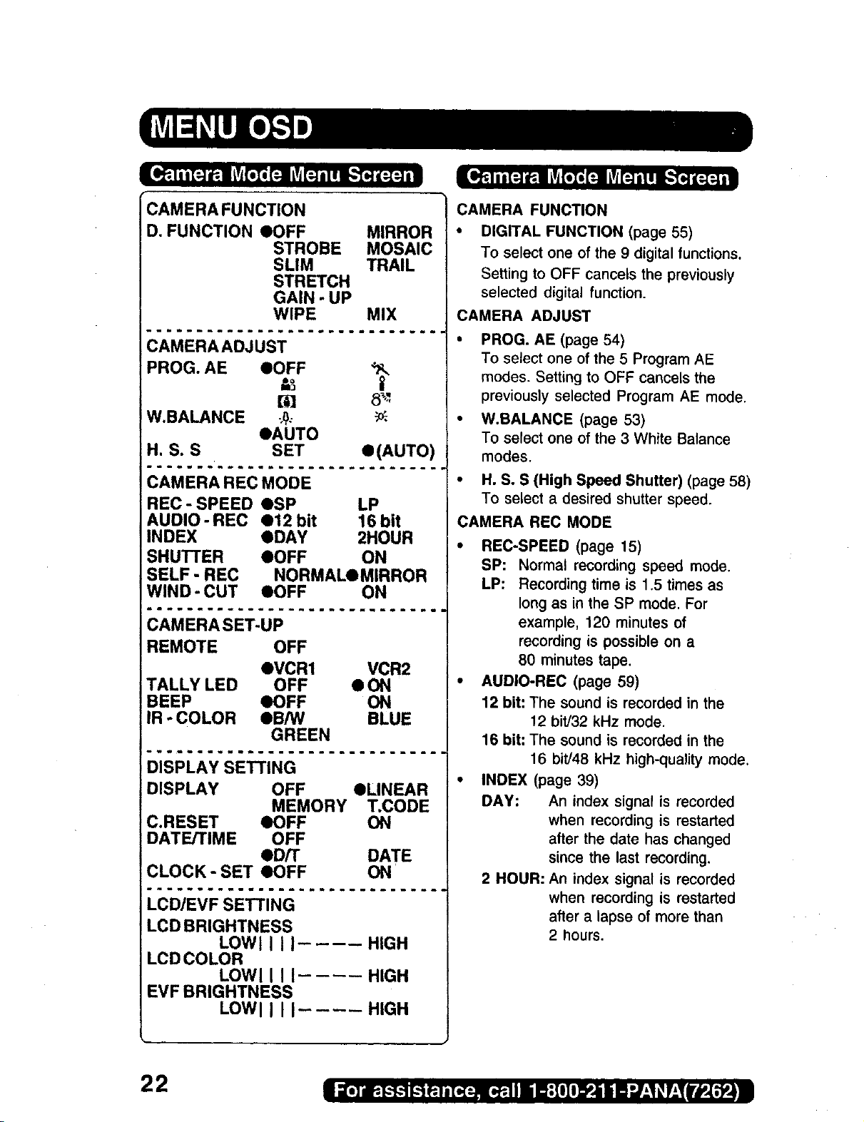
CAMERA FUNCTION
D, FUNCTION OOFF MIRROR
STROBE MOSAIC
SLIM TRAIL
STRETCH
GAIN - UP
WIPE MIX
CAMERA FUNCTION
• DIGITAL FUNCTION (page 55)
To select one of the 9 digital functions.
Setting to OFF cancels the previously
selected digital function.
CAMERA ADJUST
...............
PROG. AE eOFF
t,_ II
t_D 8_'-
W.BALANCE ;_,.- _.
OAUTO
H. S. S SET
•(AUTO)
............
REC - SPEED OSP LP
AUDIO- REC O12 bit 16bit
INDEX eDAY 2HOUR
SHUTI'ER eOFF ON
SELF - REC NORMALQMIRROR
WIND-CUT eOFF ON
............."
REMOTE OFF
OVCR1 VCR2
TALLY LED OFF • ON
BEEP OOFF ON
IR - COLOR QB/W BLUE
GREEN
..............
DISPLAY OFF eLINEAR
MEMORY T.CODE
C.RESET eOFF ON
DATE/TIME OFF
eD/T DATE
CLOCK- SET OOFF ON
..............
LCD BRIGHTNESS
LOWll II HIGH
LCDCOLOR
LOWl I I I.... HIGH
EVF BRIGHTNESS
LOWl I I I.... HIGH
• PROG. AE (page 54)
To select one of the 5 Program AE
modes. Setting to OFF cancels the
previously selected Program AE mode.
• W.BALANCE (page 53)
To select one of the 3 White Balance
modes.
• H.S. S (High Speed Shutter) (page 58)
To select a desired shutter speed.
CAMERA REC MODE
• REC-SPEED (page 15)
SP: Normal recording speed mode.
LP: Recording time is 1.5 times as
long as in the SP mode. For
example, 120 minutes of
recording is possible on a
80 minutes tape.
• AUDIO-REC (page 59)
12 bit: The sound is recorded in the
12 bit/32 kHz mode.
16 bit: The sound is recorded in the
16 bit/48 kHz high-quality mode,
• INDEX (page 39)
DAY: An index signal is recorded
when recording is restarted
after the date has changed
since the last recording.
2 HOUR: An index signal is recorded
when recording is restarted
after a lapse of more than
2 hours.
22

SHUTTER (page 52)
When set to ON, still pictures taken in
the Photo Shot mode are recorded with
a visual shutter effect and click sound.
• SELF-REC (page 31)
NORMAL: During self-recording, the
picture on the LCD Monitor
is the same as it will be
recorded.
MIRROR: During self-recording, the
picture on the LCD Monitor
is horizontally reversed.
• WIND-CUT (PV-DV400 only) (page 30)
To reduce sound distortion caused by
wind hitting the microphone. However,
this slightly deteriorates the sound
reproduction in the bass range.
CAMERA SET-UP
REMOTE (page 34)
VCR1 :To receive signals from the
Remote Control set to VCRI.
VCR2:To receive signals from the
Remote Control set to VCR2.
OFF: To prevent reception of signals
from the Remote Control.
DISPLAY SETTING
DISPLAY (page 26)
To select the desired type of display
and counter indication displayed on the
LCD Monitor or in the viewfinder.
• C.RESET (page 26)
Setting to ON, resets the counter to
zero.
• DATE/TIME (page 27)
To display the date and time on the
screen.
• CLOCK-SET (page 19)
When set to ON. the date and time can
be set on the screen.
LCD/EVF SETTING (PV-DV400 only)
• LCD/EVF SETTING (page 31)
Setting to ON displays the menu for
adjusting the LCD brightness and color
level and the viewfinder brightness.
LCD SETTING (PV-DV200 only)
• LCD SETTING (page 31)
Setting to ON displays the menu for
adjusting the LCD brightness and LCD
color.
• TALLY-LED (page 30)
Tally LED lights during recording when
set to ON.
• BEEP
Set to ON to beep when starting and
stopping camera recording or when
unusual conditions occur. To cancel the
beep, set to OFF.
Palmcorder will beep:
• Once when you start recording
• Twice when you stop recording
• Repeatedly when warning of
unusual conditions (pages 28, 29).
• IR-COLOR (PV-DV400 only) (page 53)
To select one of the 3 IR-COLOR
modes after slide IR FILTER Switch to
ON.
/
CARD SETTING
REC MODE NORMALOFINE
CARD SETTING
• REC MODE (page 41)
To select Photo Rec Mode.
23
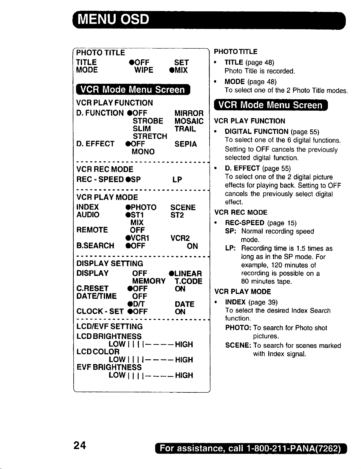
_PR-OT-OTITLE
TITLE eOFF SET
MODE WIPE eMIX
VCR PLAY FUNCTION
D. FUNCTION IOFF MIRROR
STROBE MOSAIC
SLIM TRAIL
STRETCH
D. EFFECT eOFF SEPIA
MONO
PHOTO TITLE
• TITLE (page 48)
Photo Title is recorded,
• MODE (page 48)
To select one of the 2 Photo Title modes,
VCR PLAY FUNCTION
DIGITAL FUNCTION (page 55)
To select one of the 6 digital functions.
Setting to OFF cancels the previously
selected digital function.
VCR REC MODE
REC - SPEED OSP LP
VCR PLAY MODE
INDEX OPHOTO SCENE
AUDIO QST1 ST2
MIX
REMOTE OFF
QVCR1 VCR2
B.SEARCH IOFF ON
DISPLAY SETTING
DISPLAY OFF OLINEAR
MEMORY T.CODE
C.RESET eOFF ON
DATE/TIME OFF
OD/T DATE
CLOCK- SET eOFF ON
LCD/EVF SETTING
LCD BRIGHTNESS
LOWII II .... HIGH
LCD COLOR
LOWII II .... HIGH
EVF BRIGHTNESS
LOWII II HIGH
D. EFFECT (page 55)
To select one of the 2 digital picture
effects for playing back. Setting to OFF
cancels the previously select digital
effect.
VCR REC MODE
• REC-SPEED (page 15)
SP: Normal recording speed
mode.
LP: Recording time is 1.5 times as
long as in the SP mode. For
example, 120 minutes of
recording is possible on a
80 minutes tape.
VCR PLAY MODE
INDEX (page 39)
To select the desired Index Search
function.
PHOTO: To search for Photo shot
pictures.
SCENE: To search for scenes marked
with Index signal.
24
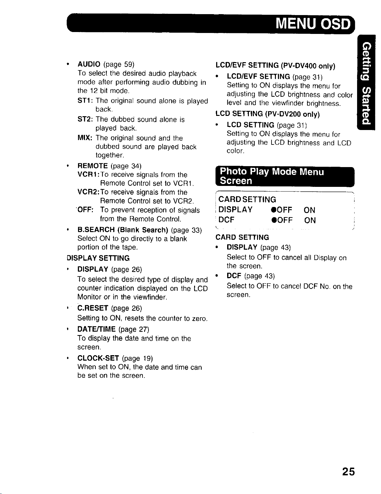
• AUDIO (page 59)
To select the desired audio playback
mode after performing audio dubbing in
the 12 bit mode.
ST1: The original sound alone is played
back.
ST2: The dubbed sound alone is
played back.
MIX: The original sound and the
dubbed sound are played back
together.
• REMOTE (page 34)
VORI'To receive signals from the
Remote Control set to VCR1.
VOR2:To receive signals from the
Remote Control set to VCR2.
'OFF: To prevent reception of signals
from the Remote Control.
• B.SEARCH (Blank Search) (page 33)
Select ON to go directly to a blank
portion of the tape.
DISPLAY SETTING
, DISPLAY (page 26)
To select the desired type of display and
counter indication displayed on the LCD
Monitor or in the viewfinder.
LCD/EVF SETTING (PV-DV400 only)
• LCD/EVF SETTING (page 31)
Setting to ON displays the menu for
adjusting the LCD brightness and color
level and the viewfinder brightness.
LCD SETTING (PV-DV200 only)
LCD SETTING (page 31)
Setting to ON displays the menu for
adjusting the LCD brightness and LCD
color.
CARD SETTING
i DISPLAY OOFF ON
DCF OOFF ON
\
CARD SETTING
• DISPLAY (page 43)
Select to OFF to cancel all Display on
the screen.
• DCF (page 43)
Select to OFF to cancel DCF No. on the
screen.
, €.RESET (page 26)
Setting to ON, resets the counter to zero.
, DATE/TIME (page 27)
To display the date and time on the
screen.
• CLOCK-SET (page 19)
When set to ON, the date and time can
be set on the screen.
25

Here are some of the basic indications which will appear on the Palmcorder EVF and
LCD Monitor. All indications except, the Date and Time, will NOT be recorded onto the
tape.
e f
a
b
C J
d J
a. Battery Remaining
FULL
EMPTY
m
• t •
J:[-"0-"_-'21 : - IEIS3OOxl
"ID.ZOOMIIIWA R N I N GI r o _A.'0"MF7
IVOLUME [-] I III
112:34:56 AM 1
JAN 2 2000
f. Display OrdOff and Counterfrime Code
The indication switches as shown below
when the desired "DISPLAY" mode is
selected from the menu (page 23).
• When selecting OFF, all displays turn
LinearTime Counter Memory Counter
[*]I
off.
b. Tape Remaining
(AY-DVM30EA) (AY-DVM60EA)
R0:30 R1:00
! !
• I • • I •
- RO:O0- - RO:OO-
t % i %
• It will take several seconds for the tape
remaining indicator to operate after the
tape starts moving.
C,
Digital Zoom and other Digital
Function (page 51)
This display appears when the digital
zoom function has been activated.
d. Playback Effect (page 55)
This display appears when SEPIA or
MONO is selected in VCR menu.
e. Tape Speed Indication (page 22)
Indicates the tape speed (SP or LP).
26
Time Code
Memory Counter M 0:00:00
The Palmcorder wil! stop whenever it
reaches the point where the counter was
previously set to M 0:00:00 during audio
dub, fast forward or rewind.
Time Code 0h00m00s00f
The Palmcorder calculates and displays
exactly where you are on any tape in terms
of hours, minutes, seconds, and frames
(30 frames = 1 second).
• This display can not be reset.
IMPORTANT NOTE:
Display must be set to ON for MF, AE,
W.BALANCE or BACK LIGHT indications to
be displayed on the EVF or LCD Panel
when selected.

_I---_VOLUME |-] I III----
g --I_A. 2 20001
h
I 112:34:s6AM I
\-
k
P,q
[÷JI
Volume Display (page 35)
g,
The volume bar appears when the
volume of the built-in speaker is being
adjusted.
h. Date and Time Indication
(pages 23, 25)
As shown below, the date and time
indication changes each time the DATE/
TIME is selected from the Palmcorder's
MENU (pages 23, 25) or the DATE/TIME
Button is pressed on the remote (optional).
12:34:56AM 1
JAN 2 2000
DAT iME
I<-'I A.22000
OFF DATE
k. Tape Modelndications
REC Recording.
PHOTO
PAUSE
PLAY
R_>
CHK
FF
REW
<_
BLANK
SEARCH
II
I. Digital EIS Indications (page 50)
m. Zoom Magnification Level (page 51)
n. Manual Focus Indication (page 56)
o. White Balance Indication (page 53)
p. PROGRAM-AE indication (page 54)
Photo Shot Recording.
Paused during recording.
Playback.
Repeat Playback.
Recording Check.
Fast forward.
Rewind.
FF Search.
REW Search.
Blank Search.
Index Search.
Mirror feature recording.
Paused during Mirror feature
recording.
WARNING indication (pages 28, 29)
The warning displays appear in the
EVF and the LCD monitor.
IR FILTER (PV-DV400 only) (page 53)
This display appears when IR FILTER
is set ON.
q. Backlight Indication (page 57)
r. Shutter Mode indication (page 58)
27
 Loading...