

Page 1
ORDER NO. MKE0010502S1
Effective from: COMMON
Supplement
Subject: Service Manual Correction
Please use this manual together with the Service Manual for Order No. MKE0009503C1;
Model No. PV-DC3000.
Please correct the Service Manual as follows.
REPLACEMENT PARTS LISTS
The Mechanical Replacement Parts List have been corrected as follows.
Ref. No. Wrong Part No. Correct Part No. Part Name
5 LSQL1093 - - - - - - - - - - CAUTION LABEL
6 - - - - - - - - - - LSEK0408 (2 pcs) TERMINAL CUSHION
7 - - - - - - - - - - LSQL1128 BATTERY LABEL
38 LSQL1001 LSQL1127 BATTERY LABEL
131 LSPG0639 - - - - - - - - - - PACKING CASE,PAPER
132 LSQT0305A - - - - - - - - - - INSTRUCTION BOOK
134 - - - - - - - - - - PV-SAC10D AC ADAPTOR
437 XQN14+B2FNK (6 pcs) XQN14+B2FNK (2 pcs) SCREW,STEEL
442 - - - - - - - - - - XQN14+B15 (4 pcs) SCREW,STEEL
Digital Camera
Model No. PV-DC3000
The Service Fixtures and Tools List have been corrected as follows.
Ref. No. Wrong Part No. Correct Part No. Part Name
- - - - - - - - - - LSJA0236 RS232C CABLE
The Electrical Replacement Parts List have been corrected as follows.
Ref. No. Wrong Part No. Correct Part No. Part Name
R1038 ERJ2RKF3901 ERJ2GEJ561X MGF CHIP 1/16W 560
R1041 ERJ2RKF5101 ERJ2RKF3901 MGF CHIP 1/16W 3.9K
R1045 ERJ2GEJ182X ERJ2GEJ331X MGF CHIP 1/16W 330
R3069 ERJ2GE0R00X ERJ3GEY0R00V MGF CHIP 1/10W 0
C1035 - - - - - - - - - - ECUV0J106KBM C CHIP 6.3V 10
C1059 ECUE1A104KBQ ECUV1C104KBV C CHIP 16V 0.01
C3003 VCEWN0JS106T ECST0JX476R TANTALUM CHIP 6.3V 47
! WARNING
This service information is designed for experienced repair technicians only and is not designed for use by the general public.
It does not contain warnings or cautions to advise non-technical individuals of potential dangers in attempting to service a product.
Products powered by electricity should be serviced or repaired only by experienced professional technicians. Any attempt to service or
repair the product or products dealt with in this service information by anyone else could result in serious injury or death.
®
© 2000 Matsushita-Kotobuki Electronics Industries LTD.
All rights reserved. Unauthorized copying and distribution
is a violation of law.
-1-
Printed in Japan
Page 2
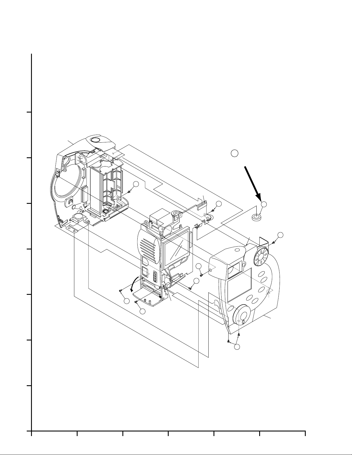
EXPLODED VIEWS
The Exploded Views have been corrected as follows.
MAIN PARTS SECTION
H
Note:
1. Parts with no Ref. No. in "EXPLODED VIEW" are not supplied.
And some Ref. No. will be skipped. Be sure to make your
orders of replacement parts according to the parts list.
2. Disregard Ref. No. suffixes when ordering parts. They are used
to describe parts in "Disassembly/Assembly Procedures" section.
G
Front Case Ass’y
TERMINAL CUSHION
6
Added
F
E
D
C
Open
439
440
-1
P8001
439
-4
-1
440
-5
410
-4
-3
439
P2004
(L-1)
6
-1
440
Rear Case Ass’y
-2
439
B
A
1
2 3 4 5 6
-2-
Page 3
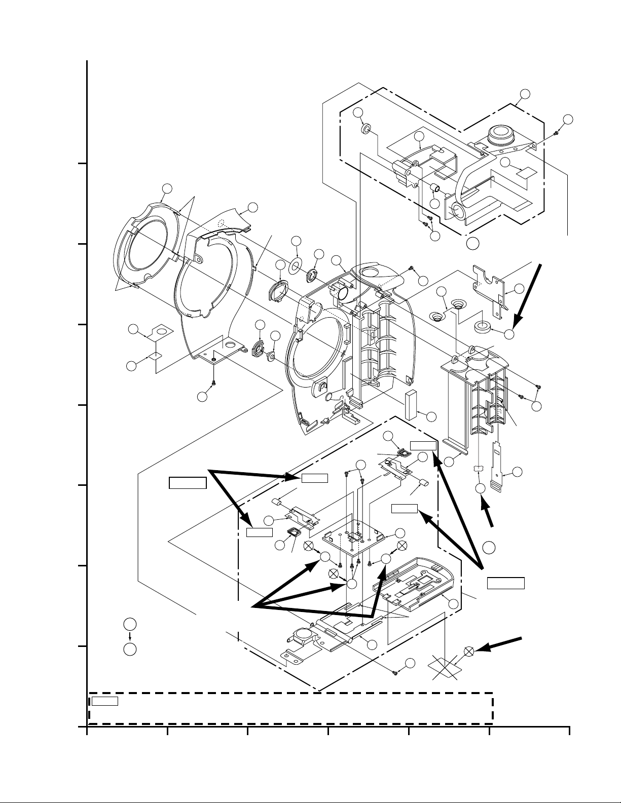
FRONT CASE SECTION
A
B
C
D
E
F
G
H
1
2 3 4 5 6
437
442
439
410
440
439
416
410
442
442
E20
16
12
17
71
13
14
15
19
20
11
18
25
23
22
23
25
21
24
2
7
5
1
4
3
711
713
714
712
6
Barrier Tube
Barrier Tube
NOTE 1
NOTE 1
NOTE 1
NOTE 1
NOTE 1 : Only for early products; the Barrier Tube is used.
When servicing Barrier Tube or Terminal Common Lower, replace only the Battery Terminal Common Lower with a new one
and remove the Battery Tube.
-4
Battery Cover Ass’y
(L-6)
(L-6)
(L-5)
-8
-8
-8
-7
(L-3)
(L-4)
(L-3)
(L-1)
(L-2)
-6
-1
-3
-5
-2
Added
6
TERMINAL CUSHION
Corrected
437
-8
442
-8
XQN14+B15(Screw)
XQN14+B2FNK(Screw)
Added
Added
NOTE 1
Added
NOTE 1
437
437
437
Added
7
BATTERY LABEL
Deleted
-3-
Page 4
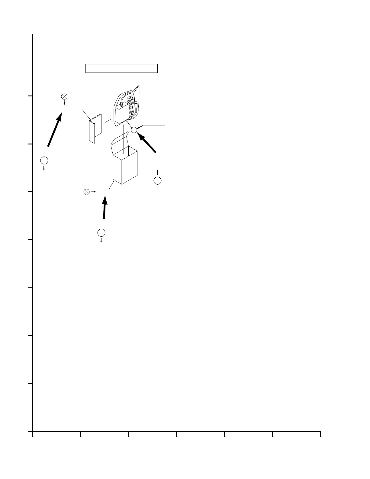
OPTIONAL ACCESSOR Y SECTION
H
G
Corrected
132
F
not supplied
E
PV-SAC10 (AC ADAPTOR)
132
not supplied
INSTRUCTION BOOK
not supplied
131
Corrected
131
not supplied
134
PACKING CASE
Corrected
not supplied
AC ADAPTOR
134
not supplied
D
C
B
A
1
2 3 4 5 6
-4-
Page 5

DISASSEMBLY/ASSEMBLY PROCEDURES
CABINET SECTION
The Disassembly/Assembly Procedures have been corrected as follows.
MAIN PARTS PORTION
STEP
Ref.
No.
No.
6
115
21-
-2
3D2
PART REMOVE
Terminal Cushion
Rear Case Ass’y
Front Case Ass’y
A B C D E F
How to read chart shown above:
A: Order of Procedure steps.
When reassembling, perform steps(s) in reverse order.
B: Ref No.
C: Part to be removed or installed.
D: Fig. No. showing Procedure or Part Location.
E: Identification of part to be removed, unhooked, unlocked,
released, unplugged, unclamped, or unsoldered.
-1) = 4 Screws (
4(
437
F: Refer to "Notes in chart."
437
Fig.
No.
D2
-----
D4
3( -1),2( -2),
D2
-1), 2(L-1) = 2 Looking Tabs (L-1)
440 439
( -3),(L-1),
439
P2004
2( -4),( -5),
439 410
P8001
NOTE
Added
Notes in chart
15.Removal of Terminal Cushion
Removed Terminal Cushions are not reusable. If removed,
install a new one.
Added
-5-
Page 6

Front Case Ass’y
440
TERMINAL CUSHION
6
Added
-1
P8001
-4
439
6
Open
439
(L-1)
440
-1
410
-5
-4
439
-3
P2004
439
-2
440
-1
Rear Case Ass’y
Fig. D2
-6-
Page 7

BATTERY COVER PORTION
STEP
No.
Ref.
No.
PART REMOVE
Fig.
No.
NOTE
1
21
Battery Cover Unit
Hinge Unit
24
2
Battery Cover
22
3
4
5
Piece
25
Protector
Battery Terminal
23
Common Lower
D4
2( -7),2(L-5)
-----
D4
4( -8)
D4
2(L-6)
D4
-----
D4
437
442
Corrected
-
-
-
-
-
A B C D E F
How to read chart shown above:
A: Order of Procedure steps.
When reassembling, perform steps(s) in reverse order.
B: Ref No.
C: Part to be removed or installed.
D: Fig. No. showing Procedure or Part Location.
E: Identification of part to be removed, unhooked, unlocked,
released, unplugged, unclamped, or unsoldered.
-1) = 4 Screws (
4(
437
F: Refer to "Notes in chart."
-1), 2(L-1) = 2 Looking Tabs (L-1)
437
-7-
Page 8

E20
(L-3)
16
(L-3)
19
20
439
Added
NOTE 1
Corrected
XQN14+B2FNK(Screw)
437
-8
XQN14+B15(Screw)
442
-8
714
711
712
NOTE 1
(L-5)
410
-4
440
23
-1
18
713
416
-3
4
1
TERMINAL CUSHION
6
3
6
(L-1)
410
(L-2)
2
7
Added
BATTERY LABEL
7
Added
NOTE 1
Battery Cover Ass’y
21
Deleted
5
12
(L-4)
71
17
NOTE 1
437
442
11
-8
437
442
437
-8
(L-6)
-7
24
25
Barrier Tube
NOTE 1
22
437
442
-8
13
15
14
-5
Barrier Tube
23
NOTE 1
25
(L-6)
439
Added
-6
-2
Added
NOTE 1 : Only for early products; the Barrier Tube is used.
When servicing Barrier Tube or Terminal Common Lower, replace only the Battery Terminal Common Lower with a new one
and remove the Battery Tube.
Fig. D4
-8-
Page 9

SCREWS FOR DISASSEMBLY/ASSEMBLY
410
416
Side View
ColorRef. No.
Gold
Silver
439
440
Side View
ColorRef. No.
Silver
Black
436
437
438
Silver
Black
Silver
442
Gold
Added
-9-
Page 10

ADJUSTMENT PROCEDURES
The Adjustment Procedures have been corrected as follows.
SERVICE FIXTURES AND TOOLS
Extension Cable -1
LSUA0017
LSUA0018Extension Cable -2
VFK1175Extension Cable -3
LSUA0030Extension Cable -4
Gray Scale Chart
Yellow Chart Red Chart
VFK1164TFYE1 VFK1164TFRE1
Infinity Lens
(with Focus Chart)
RS232C Cable LSJA0236
VFK1164TFGS2
VFK1164TCM02
ERG5SJ102
You may substitute this Resistor with an equivalent type.
USB, RS232C, A/V Gather Cable
LSUP0013
Corrected
Light Box
and AC Adaptor
VFK1164LBX1
AC Adaptor for C-Movie
can be used. (DC +6 V)
Either plug can be used.
AC Adaptor is not supplied
Added
-10-
Page 11

TEST EQUIPMENT
T o do all of the electrical adjustments, the following equipment
is required.
1. Dual-Trace Oscilloscope
Voltage Range : 0.001 V to 50 V/Div.
Frequency Range: DC to 50 MHz
Probes : 10:1, 1:1
2. Monitor TV
3. Personal Computer
PC: IBM PC/AT or compatible
OS: Windows 95 or Windows 98
CPU: 486 or higher
RAM: 8 MB on-board memory
Drive: 3.5 inch 1.44 MB floppy disk drive
Port: D-Sub 9pin Serial
Monitor: VGA Color
Other: Mouse or other pointing device
4. Frequency Counter
5. Light box (VFK1164LBX1) used for Back Focus Adj.
6. Light box (2000 lux) used for Shutter Adj.
7. RS232C Cable (LSJA0236)
Added
Corrected
Corrected
8. USB, RS232C, A/V GATHER CABLE (LSUP0013)
9. Infinity Lens with Focus Chart (VFK1164TCM02)
10.Gray Scale Chart (VFK1164TFGS2)
11.Red Chart (VFK1164TFRE1)
12.Yellow Chart (VFK1164TFYE1)
13.Color Temperature Conversion Filter 80A or equivalent
14.Color Compensating Filter CC05M
15.PC-EVR Adjustment Program (VF9S100SDV12)
Note:
Ask latest version when placing order for PC-EVR Adjustment program.
Fig. P1
PREPARATION
1. Remove the Rear Case Ass’y. Refer to "DISASSEMBLY/
ASSEMBLY PROCEDURES."
2. Connect P2004 on the Main C.B.A. and the Rear Case
Ass’y using the Extension Cable-4 (LSUA0030).
3. Connect the AC Adapter to the Digital Camera.
4. Connect the Digital Camera with the Personal Computer
and Monitor TV using the RS232C Cable (LSJA0236) and
the USB, RS232C, A/V Gather Cable (LSUP0013).
5. Set the Digital Camera Mode Dial switch to "REC" . The
picture will appear in LCD Monitor after approx. 5
seconds.
DC IN
(T o AC Adaptor)
8PIN JACK SOCKET
(To Monitor TV and PC)
RS232C Cable
USB, RS232C, A/V
Gather Cable
Monitor TV
Personal Computer
<Computer Assisted Adjustment System>
AC Adaptor
Rear Case Ass’y
Extension Cable-4
Mode Dial Switch
+
-
G
N
D
DC Power Supply
(Apply +3.3 VDC)
-11-
Page 12

CAMERA ADJUSTMENT
Back Focus Adjustment
Aim the Digital Camera at the Focus Chart so that the Focus
Chart picture on the LCD Monitor becomes centered as shown
in Fig. E3.
Fig. E3
(AUTOMATIC ADJUSTMENT only)
Note:
Place the Digital Camera in position so that A is equal to
width B.
F Data / Shutter Adjustment
Equipment : Fluorescent Lamp (SQ967B),
White Paper (5 cm x 5 cm) x 1 pc.
Set the Digital Camera and Flouorescent Lamp and White
Paper as shown in Fig. E5.
Note:
When adjusting F Data, set distance between Digital
Camera and Flouorescent Lamp within 1 cm.
Color Gain and Phase
Note:
Remove the Focus Chart before performing this
adjustment.
Set the Digital Camera, Infinity lens and (Yellow/Red Chart :
AUTOMATIC ADJUSTMENT, Yellow Chart and Red Chart :
MANUAL ADJUSTMENT) as shown in Fig. E4.
Adjustment
Fig. E5
Corrected
White Balance Adjustment
Note:
Remove the Focus Chart before performing this
adjustment.
Set the Digital Camera, Infinity lens, Gray Scale Chart and as
shown in Fig. E6.
Fig. E4
Fig. E6
-12-
 Loading...