

Page 1
Digital Camera
Operating Instructions
R
PV-DC1580
For assistance, call 1-800-272-7033.
Please read these instructions thoroughly before operating this product.
Page 2
Things You Should Know
Thank you and congratulations
on your purchase of this state of the art
Panasonic Digital Camera. This product
has been manufactured and tested to
Panasonic’s highest standards to give you
the best in performance and reliability.
Save this operating instruction manual
as an operating and information guide.
Date of Purchase
Dealer Purchased From
Dealer Address
Dealer Phone No.
Model No.
Serial No.
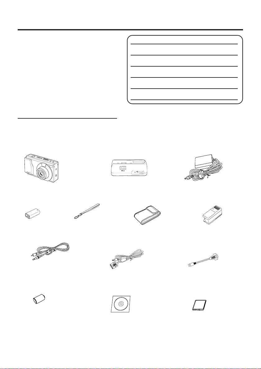
Unpack your Digital Camera
Please confirm that the following items are packed in the Digital Camera box. They are
provided to help you use or set up your Digital Camera.
1pc. Digital Camera
(PV-DC1580)
1pc. Ni-Cd
Battery Pack
(PV-BPN10)
1pc. Hand Strap
(LSFC0002)
1pc. Digital Camera Station
(LSSQ0141)
1pc. Soft Carrying
Case
(LSFC0007)
1pc. AC Adaptor
(LSSQ0142)
1pc. Detachable
Flash Unit
(PV-DF18)
1pc. Video Cable
(LSJA0184)
1 pc. Lithium Battery
(CR-2/B)
Microsoft, Windows, and Windows 95 are registered trademarks of Microsoft in the United
States and other countries.
Macintosh is a registered trademark of Apple Computer Incorporated.
CompactFlash is a trademark of SanDisk Corporation.
All product/brand names are trademarks or registered trademarks of the respective holders.
1pc. PC Connection Cable
for Windows
(LSJA0185)
1 pc. CD-ROM of Driver
Software for Windows 95
and Macintosh
1pc. PC Connection Cable
Adaptor for Macintosh
(LSJA0147)
1 pc. 8 MB
CompactFlash Card
(LSFA0007, or LSFA0008)
2
Page 3

Information
Note: This equipment has been tested and found to comply with the limits for a Class B digital device,
pursuant to Part 15 of the FCC Rules. These limits are designed to provide reasonable protection
against harmful interference in a residential installation. This equipment generates, uses and can radiate radio frequency energy and, if not installed and used in accordance with the instructions, may
cause harmful interference to radio communications. However, there is no guarantee that interference
will not occur in a particular installation. If this equipment does cause harmful interference to radio or
television reception, which can be determined by turning the equipment off and on, the user is encouraged to try to correct the interference by one or more of the following measures:
-- Reorient or relocate the receiving antenna.
-- Increase the separation between the equipment and receiver.
-- Connect the equipment into an outlet on a circuit different from that to which the receiver is connected.
-- Consult the dealer or an experienced radio/TV technician for help.
FCC Warning: To assure continued FCC compliance, use only the provided shielded interface cable
Precautions
USE & LOCATION
• TO AVOID SHOCK HAZARD ... Your Digital Camera and power supply should not be exposed to
rain or moisture. Do not connect the power supply or operate your Digital Camera if it gets wet. Your
Digital Camera has been designed for outdoor use, however it is not designed to sustain direct
exposure to water, rain, sleet, snow, sand, dust, or a direct splashing from a pool or even a cup of
coffee. This action could permanently damage the internal parts of your Digital Camera. Do not
attempt to disassemble this unit. There are no user serviceable parts inside. Unplug your Digital
Camera from the power supply and have it serviced.
• DO NOT AIM YOUR DIGITAL CAMERA AT THE SUN OR OTHER BRIGHT OBJECTS.
• DO NOT EXPOSE YOUR DIGITAL CAMERA TO EXTENDED HIGH TEMPERATURE ... Such as,
in direct sunlight, inside a closed car, next to a heater, etc... This action could permanently damage
the internal parts of your Digital Camera.
• AVOID SUDDEN CHANGES IN TEMPERATURE ... If the unit is suddenly moved from a cold place
to a warm place, moisture may form inside the unit.
• DO NOT LEAVE YOUR DIGITAL CAMERA OR THE POWER SUPPLY TURNED ON WHEN NOT
IN USE.
• STORAGE OF YOUR DIGITAL CAMERA ... Store and handle your Digital Camera in a manner that
will not subject it to unnecessary movement (avoid shaking and striking). Your Digital Camera
contains a sensitive pick-up device which could be damaged by improper handling or storage.
CARE
• TO CLEAN YOUR DIGITAL CAMERA ... Do not use strong or abrasive detergents when cleaning
your Digital Camera body.
• TO PROTECT THE LENS ... Do not touch the surface of the lens with your hand. Use a commercial
Digital Camera lens solution and lens paper when cleaning the lens. Improper cleaning can scratch
the lens coating.
• TO PROTECT THE FINISH OF YOUR DIGITAL CAMERA ... Before handling your Digital Camera,
make sure your hands and face are free from any chemical products, such as suntan lotion, as it
may damage the finish.
with ferrite cores when connecting digital camera station to computer. Also, any unauthorized changes or modifications to this equipment could void the user’s authority to
operate.
3
Page 4

Table of Contents
Things You Should Know ..................................................................................................... 2
Information ........................................................................................................................... 3
Index of Controls .................................................................................................................. 5
Attaching the Hand Strap/Soft Carrying Case ..................................................................... 7
Power Supply ....................................................................................................................... 8
Setting the Clock ................................................................................................................ 11
Using the Flash .................................................................................................................. 12
Adjusting LCD Viewfinder Brightness ................................................................................ 14
Adjusting the Iris Manually ................................................................................................. 15
On Screen Display (OSD) .................................................................................................. 16
CompactFlash Card ........................................................................................................... 17
Capturing Images............................................................................................................... 18
Capturing Close-up Images (macro) .................................................................................. 21
Playing Back Captured Images.......................................................................................... 22
To Delete Specific Images ................................................................................................. 27
To Delete All Image Pages................................................................................................. 28
Viewing Images on Your TV Screen................................................................................... 29
Transferring Your Images (VCR)........................................................................................ 30
Inserting the PCMCIA Adapter ........................................................................................... 31
Transferring Your Images (Windows 95)............................................................................ 32
Transferring Your Images (Macintosh) ............................................................................... 35
Using the Digital Photo Printer ........................................................................................... 37
Digital Camera Accessory List ........................................................................................... 38
Digital Camera Accessory Order Form .............................................................................. 39
Before Requesting Service ................................................................................................ 40
Specifications ..................................................................................................................... 41
Warranty............................................................................................................................. 42
Servicenter Directory.......................................................................................................... 43
Index .................................................................................................................................. 44
4
Page 5
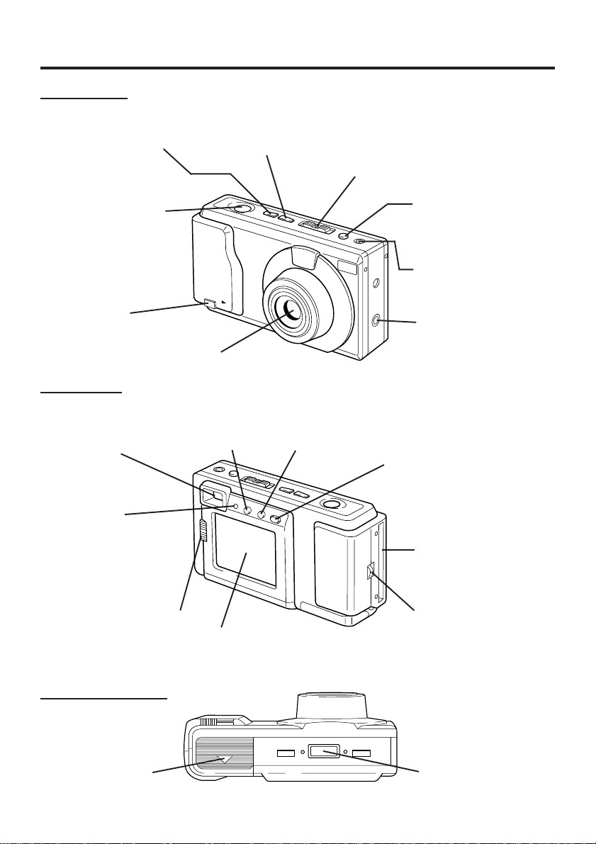
Index of Controls
Front View
− Button
+ Button
See pages 11, 14,
15, 22, 23, 24, 25,
26, 27, 37.
See pages 11, 14,
15, 22, 23, 24, 25,
26, 27, 37.
POWER Switch (PLAY•OFF•REC)
While pressing the center button, slide
the POWER switch to REC or PLAY.
See pages 11, 14, 15, 16, 19, 20, 21, 22,
23, 24, 25, 26, 27, 28, 29, 30, 34, 36, 37.
SHTR (SHUTTER)
Button
See pages 19, 20,
21, 24, 25.
Card Eject
Switch
See page 17.
Rear View
Optical
Viewfinder
See page 20.
LED Lamp
See pages 11, 14, 15,
16, 17, 19, 20, 21, 22,
23, 24, 25, 26, 27, 28,
29, 30, 34, 36.
NORMAL/MACRO1/
MACRO2 Switch
See page 21.
Lens
IRIS Button
See pages 15, 37.
LCD Viewfinder
See pages 14, 19.
MODE Button
See page 11, 18,
19, 20, 24, 25, 26.
DEL(ETE) Button
See pages 27, 28.
Flash Connecting
Jack
See page 13.
OSD Button
See pages 11, 14, 16, 28.
LCD Button
See pages 19, 20.
CompactFlash Card
Slot
See page 17.
Strap Attachment
Ring
See page 7.
Underside View
Battery
Compartment
See page 8.
Digital Camera
Station Connecting
Terminal
5
Page 6
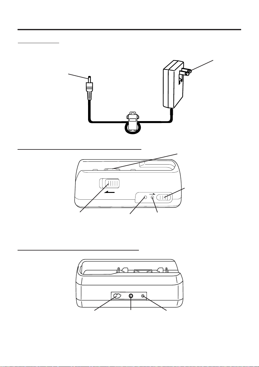
Index of Controls
AC Adaptor
DC Out Connector
See pages 9, 10.
Digital Camera Station (Front View)
AC Power Plug
See pages 9, 10.
Digital Camera
Connecting Terminal
CHARGE Switch
See page 9.
RELEASE Switch
See page 9.
POWER Lamp
See pages 9, 10.
Digital Camera Station (Rear View)
Serial Connector
See pages 34, 36.
Video Out
Connector
See pages 29, 30.
6
CHARGE Lamp
See page 9.
DC In Connector
See pages 9, 10.
Page 7
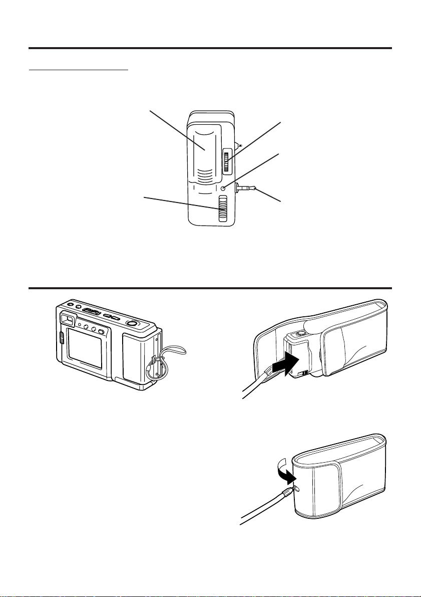
Index of Controls
Detachable Flash
Battery
Compartment
Lid
See page 12.
Clamp Ring
See page 13.
Flash LED Lamp
See page 13.
Mode Select
Switch
See page 13.
Connecting
Plug
See page 13.
Attaching the Hand Strap/Soft Carrying Case
Thread the Hand Strap through the Strap
Attachment ring as shown.
Keep the Digital Camera in the Soft
Carrying Case as shown when not in use.
You may thread the hand strap through
the hole in the Soft Carrying Case.
7
Page 8
Power Supply
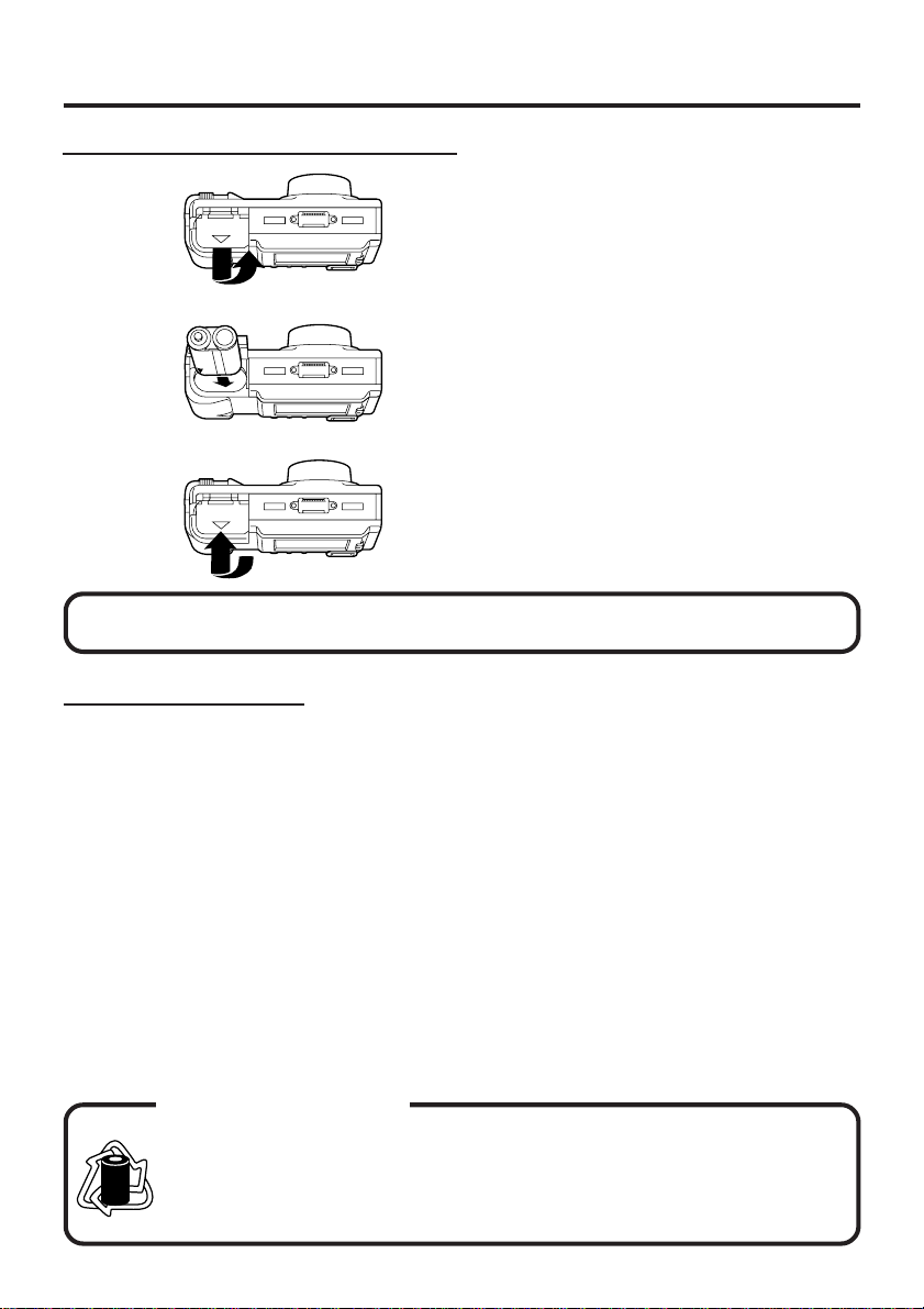
Loading the Ni-Cd Battery Pack
Underside
WARNING! Do not dispose of in fire, put in backwards, disassemble, or short circuit;
otherwise battery may leak or burst, causing possible personal injury.
1
Slide the Battery Compartment lid in the
direction of the arrow and swing it open.
2
Install the Battery Pack with the arrow
mark at the bottom and facing the rear
of the Digital Camera.
3
Swing the Battery Compartment lid
down and slide it shut.
• Charge the Battery Pack fully before
operation (see page 9).
Battery Pack Notes
Caution:
• Charge only with specified charger.
• The Battery can be charged within a
temperature range of 32° F (0° C) and
104° F (40° C).
• The Battery Pack may be warm after
charging or just after use. This is normal.
• Do not use an insufficiently charged or
worn out Battery Pack.
Safety precautions:
• Do not get the Battery Pack or AA alkaline
batteries near, or dispose of in fire.
• Do not directly connect (short circuit) the
positive (+) and negative (–) terminals.
• Never attempt to disassemble or reassemble the Battery Pack.
To avoid damage to the Battery Pack:
• Do not drop or jar the Battery Pack.
• Use the Battery Pack with specified units
only.
To insure longer Battery Pack life:
• While not in use, remove the Battery Pack
from the Digital Camera and store in a
dark, cool, dry place.
• Keep the Battery Pack terminals clean.
U.S.A. CONSUMERS:
RBRC
ATTENTION:
RBRC
The product you have purchased is powered by a nickel cadmium battery
which is recyclable. At the end of its useful life, under various state and local
laws, it is illegal to dispose of this battery into your municipal waste stream.
Ni-Cd
Please call 1-800-8-BATTERY for information on how to recycle this battery.
8
Page 9
Power Supply
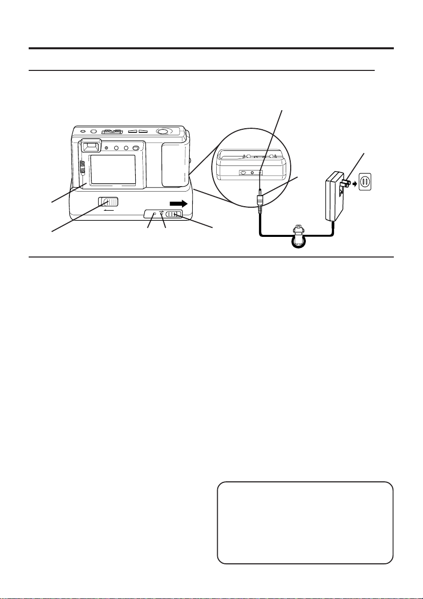
Charging the Battery Pack (PV-BPN10 or PV-BPN10/1B only)
Install the Battery Pack (see page 8.)
Charge the Battery Pack fully before operation.
DC IN
Connector
2
1
3
5
1
Connect DC OUT on the AC Adaptor
to DC IN on the Digital Camera
Station until it locks with a click.
2
Plug the AC Adaptor into an AC
outlet.
The POWER Lamp lights up.
3
Insert the Digital Camera into the
Digital Camera Station until it locks.
4
Slide the CHARGE switch.
The CHARGE Lamp lights orange, and
then changes to green when charging is
done (just under 2.5 hours).
• A red CHARGE Lamp indicates a
charge malfunction. Remove the Digital
Camera and repeat steps 3 and 4.
If the CHARGE Lamp is still red, send
the unit in for service.
5
Slide the RELEASE switch to release
the Digital Camera from the Digital
Camera Station.
• With a fully charged Battery Pack, you will
have a maximum of about 50 minutes* of
continuous playback(77°F/25°C).
* When playback 1 image every 60 seconds.
POWER
Lamp
CHARGE
Lamp
4
• The useful operation time of the Battery
will gradually decrease after repeated use
and recharging. The Battery is no longer
serviceable if the operation time is very
short, even after a sufficient charge.
• Instead of the supplied Battery Pack, you
can also use AA type Ni-Cd (high density
type) or nickel-hydride batteries available
on the market.
• For emergency use you can install 2
Panasonic alkaline batteries. But, due to
power consumption and shorter operation
life of alkaline batteries compared to the
supplied rechargeable battery pack, it is
strongly recommended that only the
Optical Viewfinder (turn off the LCD
Viewfinder) be used to capture images
when using alkaline batteries.
• If you are not going to use the Digital
Camera for an extended period of time,
remove the Battery Pack from the Digital
Camera.
CAUTION
Discharge the remaining voltage of the
Battery Pack completely before charging.
This is vital to maintain battery life and
the operation time due to characteristics
of the battery.
Do not remove the Digital Camera while
charging is in progress.
9
Page 10
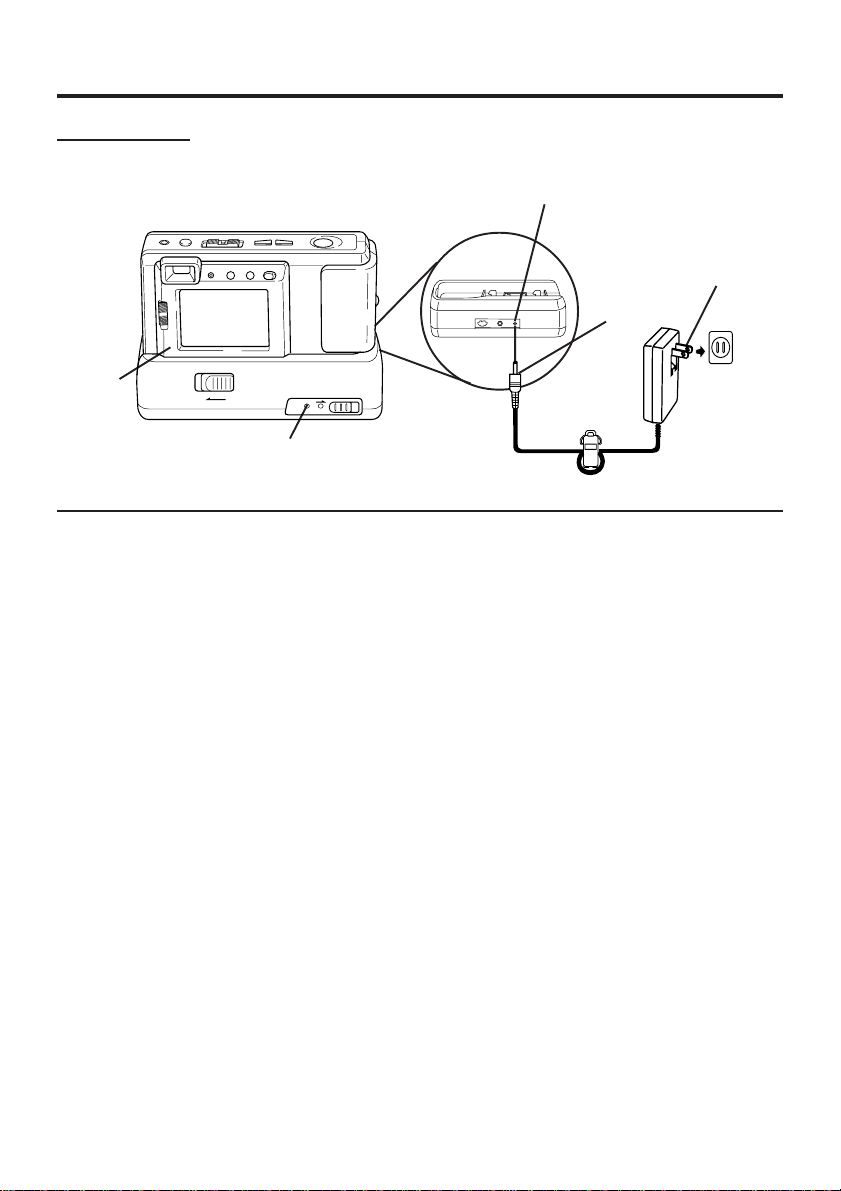
Power Supply
AC Adaptor
2
POWER
Lamp
1
Connect DC OUT on the AC Adaptor
to DC IN on the Digital Camera
Station until it locks with a click.
2
Insert the Digital Camera into the
Digital Camera Station until it locks.
DC IN
Connector
3
1
3
Plug the AC Adaptor into an AC
outlet.
• The POWER Lamp lights up.
Note:
• While not in use, unplug the AC Adaptor
from the AC outlet.
10
Page 11
Setting the Clock
LED Lamp
2
1
Set the POWER switch to REC or
PLAY.
• The LED Lamp lights up.
1 3, 42
2
Press OSD and MODE at the same
time to display the clock set screen.
CLOCK SET
10:00 AM
MAR 8 1998
+ / -
SEL
OSD
SET
3
Press (+) or (−) to select the correct
hour, then press OSD to set.
4
Repeat step 3 to select and set the
correct minute, month, date, and year.
• Double check all items before setting
the year.
Note:
• To make corrections, repeat steps 2-4.
• The clock will continue to operate about
8 hours after the battery has been
removed. If you need to reset the clock,
repeat steps 2-4.
11
Page 12
Using the Flash
1
Install the battery
1
Open the Battery Compartment lid by
sliding it in the direction of the arrow, as
shown above.
2
Install the battery as indicated inside the
Battery Compartment.
• Do not reverse the battery polarities
(−) and (+). Incorrect use may shorten
battery life, causing the battery to
become hot, leak or explode.
• Make sure the battery is firmly in place
to avoid a loose connection.
Remove the battery
• Pull up the string in the battery
compartment and remove the battery.
+
-
CAUTION
Replace with Panasonic CR2 Lithium
batteries only. Use of another battery
may present a risk of fire or explosion.
Caution-battery may explode if
mistreated.
Fire and burn hazard. Do not recharge,
disassemble, or dispose of in fire.
Keep battery out of reach of children.
Danger of explosion if battery is
incorrectly inserted. Dispose of used
battery promptly.
When disposing of the used Lithium
Battery be sure to insulate the battery
polarities (+) and (−) by covering with
cellophane tape.
2
12
Page 13
Using the Flash
2
1
Attaching the Flash
1
Pull up on the connecting plug from its
retracted position as shown above.
2
Connect to the digital camera
connecting jack.
3
Rotate thumbwheel to secure the flash.
• Be sure to set the Digital Camera and
the flash unit to OFF before attaching or
removing the flash unit.
Using the Flash
4
Slide the MODE Select Switch to one
of the following positions to use the
flash.
• AUTO The flash automatically lights
depending on lighting conditions.
• The flash will light whenever you
capture an image.
• OFF The flash will not light even when
you capture an image.
3
LOOSEN
TIGHTEN
4
NOTE:
• Please set the MODE Select Switch to OFF
when taking Macro shots (see page 21).
• The flash will not light when the unit is in
Multi Mode (see page 18).
• The LED Lamp on the flash unit lights
when flash is charged and ready.
• The effective range of the flash is roughly
3.3 feet (1m) to 8.2 feet (2.5m).
• If you are using the flash in very bright
areas, the image background may
become dark.
• While not in use, remove the battery
from the flash unit.
• Remove the flash unit when not in use.
• Never handle the flash unit if your
hands are wet. This may result in
electric shock or damage to the flash.
• Do not use the flash close to people's
faces as it may be harmful to the eyes.
Especially when capturing images of
infants or small children, keep at least
3.3 feet (1m) away.
13
Page 14
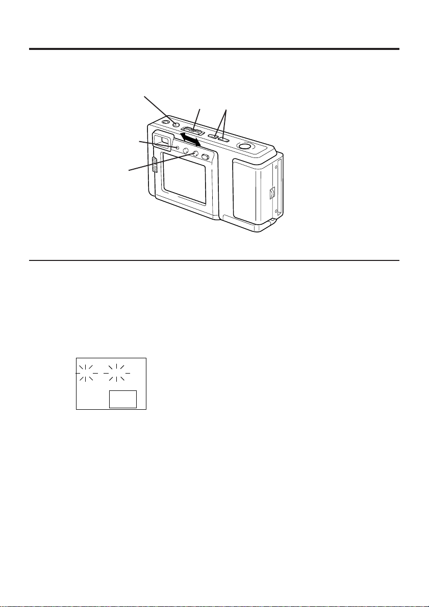
Adjusting LCD Viewfinder Brightness
You may want to brighten or darken the LCD (Liquid Crystal Display) Viewfinder for easier
viewing. This adjustment will not affect the captured image brightness.
13
LED Lamp
2, 4
1
Set the POWER switch to REC or
PLAY.
• The LED Lamp lights up.
2
Press OSD repeatedly until the
BRIGHT adjustment screen appears.
BRIGHT
+−
3
Press (+) or (−) to change the bright-
ness of the LCD Viewfinder; (+) for
brighter, (−) for darker.
• The normal screen will reappear if
either (+) or (−) is not pressed within
5 seconds.
4
Press OSD once to exit the BRIGHT
adjustment screen.
Note:
• The BRIGHT adjustment will be reset to
the original setting when the Digital
Camera is turned off.
14
Page 15

Adjusting the Iris Manually
Normally, the camera adjusts the exposure automatically. However, when the
background is extremely bright, or when the subject is backlit, you can compensate by
adjusting the Iris manually.
13
LED Lamp
2
1
Set the POWER switch to REC.
• The LED Lamp lights up.
2
Press IRIS Button to display the IRIS
screen.
IRIS
+−
3
Press (+) or (−) to change the IRIS;
Press (+) to increase the brightness,
Press (−) to decrease the brightness.
• The IRIS screen disappears about
5 seconds after the adjustment.
Note:
• There are 7 brightness compensation
levels ranging from −3 to +3.
• A blue sky may appear somewhat whiter
when the brightness is increased.
• The brightness cannot be adequately
compensated for in extreme backlight
conditions.
• The original exposure is automatically
restored when the power is turned off.
15
Page 16

On Screen Display (OSD)
The indications displayed on the LCD screen will tell you the operation status of the Digital
Camera.
REC Mode Playback Mode
Function Status
REC
LIGHT
10 FINE
Image Pages left in
memory and Image
Resolution selected;
FINE (Fine), NORMAL
(Normal), ZOOM (Zoom),
WIDE (Wide), or MULTI
(Multi).
Low Light Warning
“LIGHT” will appear
when the light level is
inadequate. In this
case, more light
should be provided or
use flash unit (See
page 13) to achieve
better picture quality
and color.
P10 FINE
Displayed Image Page and its Image Resolution
FINE (Fine), NORMAL (Normal), or WIDE (Wide).
•If the image is captured in ZOOM mode, the
displayed Image Resolution will be NORMAL.
•If the image is captured in MULTI mode, the
displayed Image Resolution will be FINE.
To Cancel the OSD
Battery Condition
FULL
EMPTY
As the Battery is depleted,
the indication changes.
LED Lamp will flash when
battery is empty.
1
LED
Lamp
2, 3
On Screen Display Order
Press
OSD
10 FINE
16
Press
OSD
1
Set the POWER switch to REC or
PLAY.
• The LED Lamp lights up.
2
Press OSD repeatedly until the On
Screen Display disappears.
3
To resume the On Screen Display,
press OSD until it reappears.
• Only Warning indications and REC
indication will be displayed on the LCD
Viewfinder if the OSD is cancelled.
• The OSD feature will be in on mode
each time the Digital Camera is
powered on.
BRIGHT
+−
Returns to OSD ON
mode if, after 5 seconds,
no selection is made.
Press
OSD
JAN 29 1998
Returns to OSD
ON mode after
5 seconds.
(REC mode)
Page 17

CompactFlash Card
LED Lamp
1, 2
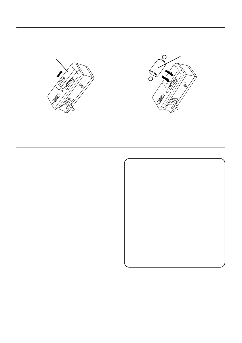
Inserting the CompactFlash Card.
• The captured images will be stored on
this CompactFlash Card.
• Be sure to insert the CompactFlash
Card before using the camera.
1
Insert the CompactFlash Card into the
slot in the direction of the arrow mark
and so that the arrow mark side of the
card faces the front (lens Side) of the
Digital Camera.
2
Push the card fully into the
CompactFlash Card Slot.
Removing the CompactFlash Card.
3
Slide the CARD EJECT Switch, so the
Card pops out. (Be careful not to drop
the card.)
3
• Do not, under any circumstances, eject
the card immediately after pressing the
Shutter Button (during recording of an
image) or while deleting (when PLEASE
WAIT is displayed). This could damage
the format of the card and make it
unusable.
• Make sure that you do not insert the card
in the wrong direction.
• When the card does not eject after
pressing the CARD EJECT Switch, push
the card fully into the slot again and then
press the CARD EJECT Switch firmly.
• To avoid dropping the card, do not push
the CARD EJECT Switch when the card
slot is facing downward.
• NO CF CARD will appear on the LCD
Viewfinder and the LED Lamp will flash
when the CompactFlash Card is not
inserted.
• CF CARD ERROR will appear on the
LCD Viewfinder and the LED Lamp will
flash if the CompactFlash Card is
defective.
17
Page 18

Capturing Images
MODE Button
To Select the Recording Mode
You can select the recording mode by
pressing the MODE switch.
Press
Mode
Normal Mode
Press
Mode
Zoom Mode
Wide Mode
• Image resolution is 1,136 X 640.
• Approx. 40 images can be stored with
supplied 8 MB CompactFlash Card.
Wide Mode
Press
Mode
Fine Mode
Press
Mode
Multi Mode
Press
Mode
• The recording mode can be switched
anytime by pressing MODE.
Fine Mode
• Image resolution is 1,024 X 768.
• Approx. 40 images can be stored with
supplied 8 MB CompactFlash Card.
Normal Mode
• Image resolution is 512 X 384.
• Approx. 152 images can be stored with
supplied 8 MB CompactFlash Card.
Zoom Mode
• Using Zoom mode magnifies the image to
twice its normal size.
• Image resolution is 512 X 384.
• Approx. 152 images can be stored with
supplied 8 MB CompactFlash Card.
Note :
Picture quality of images captured in
ZOOM mode are less than those captured
in NORMAL mode.
18
Multi Mode
• Pressing SHUTTER in Multi mode allows
you to capture an image every 0.3
seconds to create a series of nine shots.
The images are displayed in order from
the upper left corner on the screen.
• Image resolution is 1,024 X 768.
• Approx. 40 images can be stored with
supplied 8 MB CompactFlash Card.
BC
A
EF
D
HI
G
Note :
If SHUTTER is held down and then
released, the images may not be displayed
in the order shown above.
Page 19

Capturing Images
1 42
3
LED Lamp
LCD Viewfinder
Using LCD Viewfinder
1
Set the POWER switch to REC.
Make sure you slide the POWER switch
fully to the REC position.
• The LED Lamp lights up.
4
Press SHTR (SHUTTER) to capture the
image displayed on the Viewfinder.
• Press SHTR(SHUTTER) down halfway
to lock Auto Focus.
10 FINE
2
Make sure the LCD Viewfinder is on.
Press the LCD button if the LCD
Viewfinder is off.
3
Press MODE to select the recording
mode. (See page 18.)
REC
10 FINE
• REC on the LCD Viewfinder and LED
Lamp will flash while the Digital Camera
processes the image. You may capture
another image as soon as REC and
LED Lamp stops flashing.
19
Page 20

Capturing Images
1 41, 2
1
Optical Viewfinder
LED Lamp
Using Optical Viewfinder
1
Repeat step 1 and 3 on the previous
page.
2
Press the LCD button to turn off the
LCD Viewfinder.
• If you press the OSD or MODE button,
the LCD monitor will turn on.
3
Frame the image you want to capture
within the recording area guide marks
on the Optical Viewfinder.
Normal
• Please use the Short Distance frame
when capturing images within 3.3 feet
(1 m) of subject.
• Focus will be adjusted automatically in
the center mark area.
4
Press SHTR (SHUTTER) to capture the
image.
• LED Lamp will flash while the Digital
Camera processes the image.
You may capture another image as
soon as LED Lamp stops flashing.
Short Distance
20
• Using the Optical Viewfinder will
prolong battery life.
Notes for LCD and Optical Viewfinder use:
• The number of image pages left in the
selected mode is displayed on the LCD
Viewfinder. When no memory remains, 0
and LED Lamp will flash. To capture other
images, you will first need to delete some
images from memory (see pages 27, 28).
• The Digital Camera is focused automati-
cally. For close-ups, see page 21.
• If, after the POWER switch has been set to
REC or PLAY, no buttons are pressed for
one minute in REC mode or two minutes in
PLAY mode, the LCD will turn off automatically to conserve power. To resume
operation, press SHTR (SHUTTER), or set
the POWER switch to OFF, and then to
REC.
• Avoid covering the lens with your fingers
when capturing images.
• Do not subject the LCD Viewfinder to
pressure or shock.
• Hold the Digital Camera as steady as
possible when capturing an image.
• The active LCD Viewfinder image will have
a slightly degraded appearance when
compared to a captured or transferred
image. This is normal.
Page 21

Capturing Close-up Images (macro)
You can capture images of plants, insects, photo album pictures, and so on.
LED Lamp
41
2
MACRO2
MACRO1
NORMAL
1
Set the POWER switch to REC.
• The LED Lamp lights up.
2
Set the NORMAL/MACRO1/MACRO2
switch to MACRO1 or MACRO2.
• LCD Viewfinder will turn on automatically.
3
Bring the Digital Camera up to the
subject
10.6 inches (27cm) away in MACRO1 or
5.5 inches (14cm) away in MACRO2].
4
Press SHTR (SHUTTER) when the
subject is in focus.
• The LED Lamp will flash while the
Digital Camera processes the image.
• The flash will not light when the unit is
in MACRO mode.
• You may have to move the Digital
Camera closer or further away from the
subject for proper focus
• When finished with this feature, be sure
to return the NORMAL/MACRO1/
MACRO2 switch to NORMAL.
[as close as approximately
21
Page 22

Playing Back Captured Images
LED Lamp
Manual Playback
1
Set the POWER switch to PLAY.
P10 FINE
• The LED Lamp lights up.
• Turn off the LCD monitor when not in
use by pressing the LCD button. To turn
the monitor back on, press the LCD
button again.
• If you press the DEL, OSD, or MODE
button while in Play mode, the LCD
monitor will automatically turn on as a
warning.
1
3
• Page number is changed continuously
• Selected page is displayed when button
2, 3
Hold down (+) or (−), [(+) for ascending
order, and (−) for descending order] to
change the displayed image on the LCD
Viewfinder by fast page advance.
while (+) or (−) button is held down.
is released.
2
Press (+) or (−) repeatedly, [(+) for
ascending order, and (−) for descending
order] to change the displayed image
on the LCD Viewfinder.
• The image page number and resolution
mode are displayed at the bottom of the
screen.
• If there are no images in memory, a
blue back screen will be displayed.
22
Page 23

Playing Back Captured Images
1 2, 3
LED Lamp
Auto Playback
1
Set the POWER switch to PLAY.
• The LED Lamp lights up.
3
Press (+) or (−) again to cancel Auto
Playback mode.
P10 FINE
2
Hold down (+) and (−) at the same
time to place the Digital Camera in Auto
Playback mode.
AUTO PLAY
START
P10 FINE
• “AUTO PLAY START” will be displayed.
• Auto Play displays images in ascending
order only.
• Each image will remain on the LCD
Viewfinder for three seconds after it is
fully displayed.
• Auto Play will continue to loop through
the images until you cancel this feature.
AUTO PLAY
STOP
P20 FINE
• “AUTO PLAY STOP” will be displayed.
23
Page 24

Playing Back Captured Images
2, 6 5
LED Lamp
Multi Image Playback
1
Set the POWER switch to PLAY.
• The LED Lamp lights up.
P10 FINE
2
Press the MODE button. A Multi
Image Playback screen will appear.
3
Press (+) repeatedly to scroll forward
through Multi Image pages (each page
contains nine images). When you locate
the page containing the image you
want, go to step 5. The selected image
will be the one displayed on the screen.
2
4
Press (−) to move back through the
images on the page until the number of
the image you want is selected.
(+)
10
11
1
3, 4
• The number of the selected image will
be inversely displayed.
(−)
10 9
5
Press SHTR (SHUTTER). The image
you selected will be the one displayed
on the screen.
6
Press MODE to restore the Multi Image
Playback screen.
Select Playback Mode
Note:
• Press MODE repeatedly to select the
desired playback mode as shown below.
Manual
Playback
19
Press
Mode
Zoom Playback
for Multi Mode
Press
Mode
Press
Mode
Multi Image
Playback
Zoom
Playback
Press
Mode
24
Page 25

Playing Back Captured Images
LED Lamp
Zoom Playback
1
Set the POWER switch to PLAY.
• The LED Lamp lights up.
P10 FINE
2
Press (+) or (−) to select the image you
want to zoom in on.
3
Press MODE twice to enter the Zoom
Playback mode.
1 2, 4
• Pressing (−) moves the zoom area in
the opposite direction.
5
Press SHTR (SHUTTER) to zoom in on
the selected portion of the image X2.
• Press (+) or (−) to change the zooming
area.
6
Press SHTR (SHUTTER) to restore the
image to its normal size.
7
Press MODE twice to resume the
normal screen.
5, 63, 7
4
Press (+) or (−) to select the desired
Zoom Position.
Changing the Location of the Zoom Area.
Select Playback Mode
Note:
• Press MODE repeatedly to select the
desired playback mode as shown below.
Manual
Playback
Press
Mode
Zoom Playback
for Multi Mode
Press
Mode
Press
Mode
Multi Image
Playback
Zoom
Playback
Press
Mode
25
Page 26

Playing Back Captured Images
3, 4, 6
LED Lamp
1 2, 5
Zoom Playback for Multi Mode
1
Set the POWER switch to PLAY.
• The LED Lamp lights up.
P10 FINE
2
Press (+) or (−) to select the Multi
Mode Image you want to zoom in on.
• You can also zoom the Normal Mode
Image.
3
Press MODE three times to select
Zoom Playback for Multi Mode.
4
Then the upper left imagewill be zoom
in on.
• The image will be displayed X3 magnification.
ABC
DEF
GH I
Press
Mode
A
5
Press (+) or (−) to select a new image.
6
Press MODE to return to the normal
screen.
To Select Playback Mode
Note:
• Press MODE repeatedly to select the
desired playback mode as shown below.
Press (+)
A
Press (−) Press (−)
Manual
Playback
Press
Mode
Zoom Playback
for Multi Mode
Press
Mode
Press
Mode
B
Press (+)
Multi Image
Playback
Zoom
Playback
Press
Mode
C
26
Page 27

To Delete Specific Images
You can delete unwanted images and increase the remaining image memory.
Warning: Once deleted, images cannot be restored.
1 32, 4
LED Lamp
4
1
Set the POWER switch to PLAY.
• The LED Lamp lights up.
2
Press DEL to display the DELETE
menu.
DELETE
ALL
PAGE
EXIT
• To exit this menu, press SHTR.
OSD
+ / −
SHTR
Press DEL to select YES when the
image page you want to delete is
displayed.
PLEASE
WAIT
• Image page numbers are adjusted
automatically as images are deleted.
• To delete other specific image pages,
please repeat steps 2–4.
3
Press (+) or (−) to select the image
page to be deleted.
DELETE PAGE
YES
SEL
EXIT
P10 FINE
• To exit this menu, press SHTR.
DEL
+ / –
SHTR
Important:
• While “PLEASE WAIT” is displayed, do
not turn off the Digital Camera nor
unplug the AC Adaptor because this
will cause irreversible damage to the
memory, resulting in reduced image
storage capacity.
27
Page 28

To Delete All Image Pages
You can delete all images from memory with one easy operation.
Warning: Once deleted, images cannot be restored.
2, 4
LED Lamp
3
1
Set the POWER switch to PLAY.
• The LED Lamp lights up.
2
Press DEL to display the DELETE
menu.
DELETE
ALL
PAGE
EXIT
• To exit this menu, press SHTR.
OSD
+ / −
SHTR
1
4
Press DEL to select YES in the
DELETE ALL menu.
PLEASE
WAIT
• “PLEASE WAIT” will be displayed on
screen as all images are deleted from
memory. Deletion is complete when the
screen turns solid blue.
3
Press OSD to select ALL in the
DELETE menu.
DELETE ALL
YES
NO
• To exit this menu, press SHTR.
DEL
SHTR
28
Important:
• While “PLEASE WAIT” is displayed, do
not turn off the Digital Camera nor
unplug the AC Adaptor because this
will cause irreversible damage to the
memory, resulting in reduced image
storage capacity.
Page 29

V iewing Images on Your TV Screen
LED Lamp
1
Insert the Digital Camera into the
Digital Camera Station until it locks.
2
Connect the Digital Camera Station
to your TV using the Video cable
(supplied) as shown.
3
Turn on your TV and select its video
input mode.
4
1
Video Out
3
Video In
2
Video Cable
(Supplied)
4
Set the Digital Camera POWER
switch to PLAY. You may select
manual or auto playback as described
on pages 22 and 23.
• The LED Lamp lights up.
Note:
• For extended periods of use, it is
recommended to use the AC Adaptor
for a power source.
29
Page 30

Transferring Your Images (VCR)
3, 5
LED Lamp
1
Insert the Digital Camera into the
Digital Camera Station until it locks.
2
Connect the Digital Camera Station
to your VCR using the Video cable
(supplied) as shown.
3
Turn on your VCR and select its line
input mode.
4
Set the Digital Camera POWER
switch to PLAY. You may select
manual or auto playback as described
on pages 22 and 23.
• The LED Lamp lights up.
4
1
Video Out
/
Video In
2
Video Cable
(Supplied)
5
Start a recording of the desired
images. (Refer to your VCR manual.)
Note:
• For extended periods of use, it is
recommended to use the AC Adaptor
for a power source.
30
Page 31

Inserting the PCMCIA Adapter
If you are using a computer with a PCMCIA type II slot, you can insert the
CompactFlash Card into a PCMCIA adapter (not included).
Inserting the CompactFlash Card
• The adapter should be inserted when
your computer is in the power on mode.
1
Remove the CompactFlash Card from
the camera. (See page 17.)
2
Hold the CompactFlash Card so that
the arrow side faces up and points
toward the PCMCIA Adapter. Securely
insert the card into the PCMCIA
Adapter slot as far as it will go.
3
Hold the PCMCIA Adapter so that the
arrow side points toward the PCMCIA
type II slot of your computer. Securely
insert the PCMCIA Adapter as far as it
will go.
• Depending on the computer, it may be
necessary to turn the PCMCIA Adapter
upside down in order to insert the card.
Removing the CompactFlash Card
1
Remove the PCMCIA Adapter from the
computer.
2
Pull the CompactFlash Card out of the
PCMCIA adapter.
Note
Do not remove the PCMCIA Adapter from
the computer while the computer is working
or while image data is being transferred
between the CompactFlash Card and the
computer (including operation such as
opening and storing images), this will cause
irreversible damage to the memory.
If Windows 95 Explorer is opened
Up to 50 images
are stored in
Ctgxxxx folder
Sub Directory
(DC97)
Identified as
Removable
Hard Disk
Image Data is
displayed as
Aut_xxxx.jpg file
Thumbnail files
are displayed as
Thm_xxxx.jpg file
(Contains no image
data substance)
31
Page 32

Transferring Your Images (Windows 95)
System Requirements:
• IBM PC/AT or compatible.
• Windows 95.
• 386SX CPU or higher. (486 recommended.)
• RAM: 16 MB on-board memory.
• 10 MB available hard disk space.
Palmcam Camera Driver Installation
1
Turn on the PC (Personal Computer) and start up Windows.
2
Insert this disk into the CD-ROM drive.
3
Click the "Start" button and then click "Run"..
• 256 Color monitor or full color recommended (24bit per pixel or 16.7M color).
• CD-ROM drive (for installation).
• RS-232C serial port (D-Sub 9-pin). An
adaptor is required for a D-Sub 25-pin.
• Mouse or other pointing device.
4
Type in "d:\PalmCam\Setup.exe" and then click OK.
Note: "d" Denotes the CD-ROM drive designation.
5
Follow the instructions as they appear on your PC screen.
32
Page 33

Transferring Your Images (Windows 95)
Plug-in Driver for Adobe® PhotoDeluxe™ 2.0 Installation
• The Plug-in Driver, when installed, allows your camera to communicate directly with
PhotoDeluxe 2.0.
Note:
• Please install Adobe PhotoDeluxe 2.0 before installing this driver.
• For information on Adobe PhotoDeluxe, please call 206-628-5724
Web Site : http://www.adobe.com.supportservice/custsupport/main.html
1
Turn on the PC (Personal Computer) and start up Windows.
2
Insert this disk into the CD-ROM drive.
3
Click the "Start" button and then click "Run".
4
Type in "d:\Plugin\Setup.exe" and click "OK".
Note: "d" Denotes the CD-ROM drive designation.
5
When installation is completed, start up PhotoDeluxe2.0 and follow the instructions on
how to transmit images.
Adobe and PhotoDeluxe are trademarks of Adobe Systems Incorporated.
33
Page 34

Transferring Your Images (Windows 95)
LED Lamp
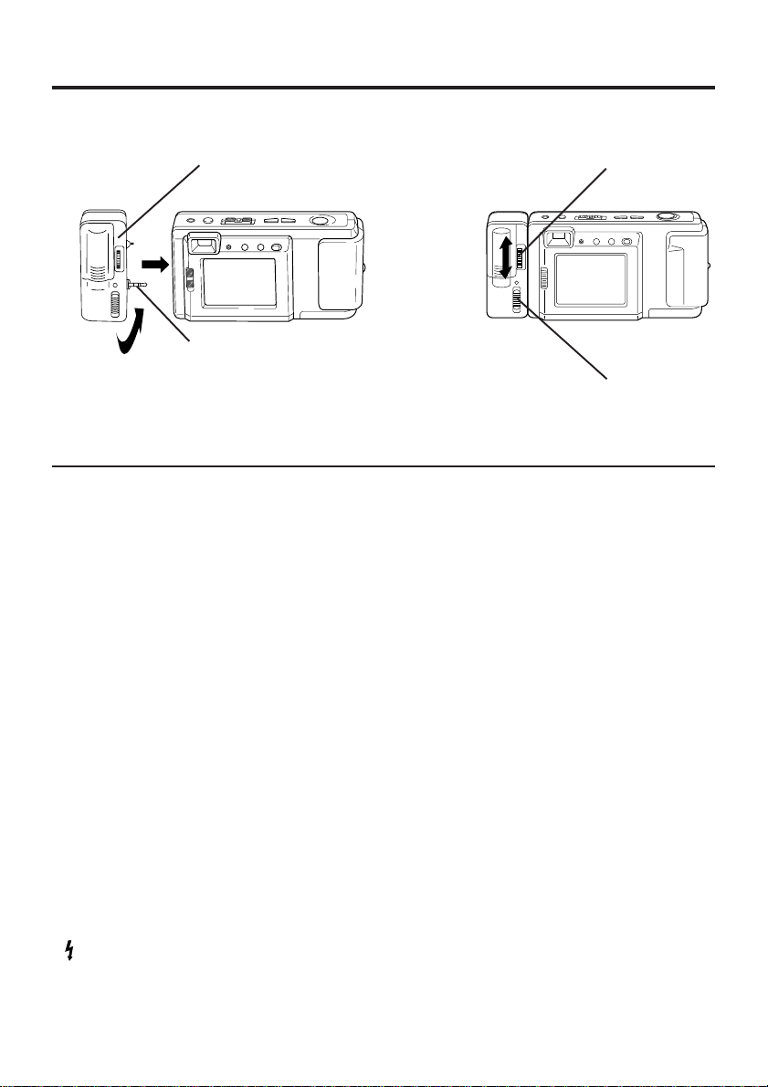
Connection
1
Insert the Digital Camera into the
Digital Camera Station until it locks.
2
Connect the Digital Camera Station
to your PC (Windows) using the PC
connecting cable (supplied) with the
arrow mark facing downward.
3
Turn on your PC.
14
Serial
2
Running the Application
5
Select Programs/PalmCam1.5/
PalmCam1.5 from the Start Menu.
3
RS-232C
(D-Sub 9-pin)
PC Connecting Cable for
Windows
(Supplied)
4
Set the Digital Camera POWER
switch to PLAY.
• The LED Lamp lights up.
Note:
• For extended periods of use, it is
recommended to use the AC Adaptor as a
power source.
• While the PC communicates with the
Digital Camera, the Digital Camera cannot
be operated.
34
6
Please read the Help information fully
before operating the application.
Page 35

Transferring Your Images (Macintosh)
System Requirements:
• System 7.1 or later.
• 68030 CPU or higher, or Power
Macintosh.
• 16 MB of RAM.
• 10MB available hard disk space.
PalmCam Camera Driver
Installation
1
Turn on the Macintosh.
2
Insert this disk into the CD-ROM drive.
3
Double click the CD-ROM icon.
4
Read the "Read Me" file.
5
Drag the "PalmCam 1.5 Folder"
where you want to copy.
• 256 Color monitor or full color recommended (24bit per pixel or 16.7M color).
• CD-ROM drive (for installation).
• Modem port or printer port (RS-422).
• Mouse or other pointing device.
Plug-in Driver for Adobe®
PhotoDeluxe™ 2.0 Installation
• The Plug-in Driver, when installed, allows
your camera to communicate directly with
PhotoDeluxe 2.0.
Note:
• Please install Adobe PhotoDeluxe 2.0
before installing this driver.
• For information on Adobe PhotoDeluxe,
please call 206-628-5724
Web Site : http://www.adobe.com.
supportservice/ custsupport/main.html
1
Turn on the Macintosh.
2
Insert this disk into the CD-ROM drive.
3
Double click the CD-ROM icon.
4
Drag the "Pdc1580.8bam" file to the
"Plug-ins" folder of PhotoDeluxe.
5
When installation is completed, start up
PhotoDeluxe 2.0 and follow the
instructions on how to transmit images.
Adobe and PhotoDeluxe are trademarks of Adobe Systems Incorporated.
35
Page 36

Transferring Your Images (Macintosh)
Modem
port or
printer port
Serial
LED
Lamp
14
3
Connection
1
Insert the Digital Camera into the
Digital Camera Station until it locks.
2
Connect the Digital Camera Station
to your PC (Macintosh) using the PC
connecting cable (supplied) and PC
Connecting Cable Adaptor for
Macintosh (supplied) with the arrow
mark facing downward.
3
Turn on your PC (Macintosh).
4
Set the Digital Camera POWER
switch to PLAY.
• The LED Lamp lights up.
2
PC Connecting
Cable for Windows
(Supplied)
PC Connecting
Cable
Adaptor for
Macintosh
(Supplied)
Running the Application
5
Double click the PalmCam icon.
6
Please read the Help file fully before
operating the application.
Note:
• For extended periods of use, it is
recommended to use the AC Adaptor as a
power source.
• While the PC communicates with the
Digital Camera, the Digital Camera cannot
be operated.
36
Page 37

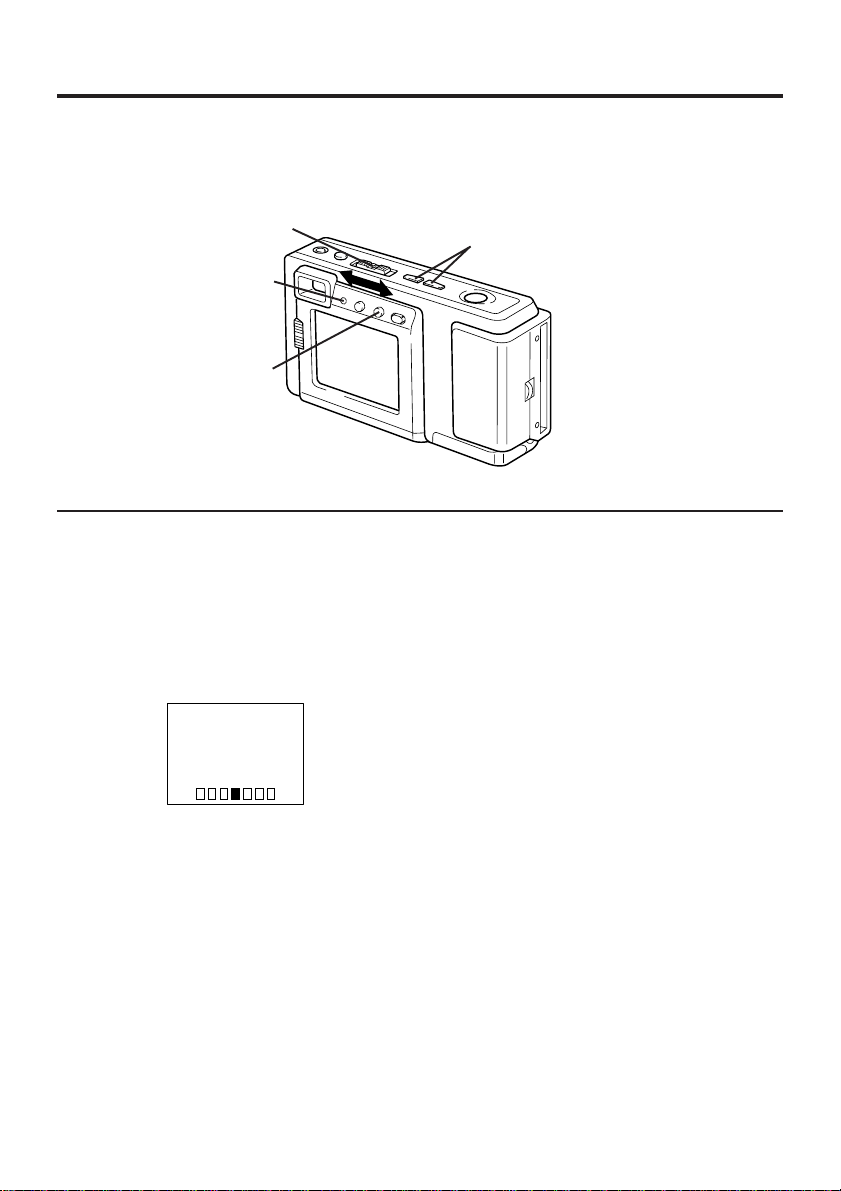
Using the Digital Photo Printer
Images can be selected for print out on a digital photo printer (sold separately).
LED Lamp
3
Stamp Print Marker
1
Set the POWER switch to PLAY.
P10 FINE
• The LED Lamp lights up.
2
Press (+) or (−) repeatedly to select the
images you want to mark for printing.
• You can mark images in either Manual
Playback Mode (see page 22), or MultiImage Playback Mode (see page 24).
3
Press IRIS to stamp a print mark on the
image. A " " mark will appear on the
image.
1
Printing on a Digital Photo Printer
1
1
2
2
• *Requires a Digital Photo Printer
• Insert the adapter in the direction of the
3
3
• The Printer access lamp will flash.
2
Remove the CompactFlash Card
containing the captured images from
the camera and insert it into the
PCMCIA Adapter (see page 31).
Connect the PCMCIA Adapter (included with printer) to the Digital Photo
Printer*.
PV-PD2000 (sold separately).
arrow and push the card fully into the
printer.
Turn on the printer and set the INPUT
SELECT (VIDEO/PC CARD) Switch to
the PC CARD position.
10 FINE
• Press IRIS again to cancel the print
mark.
• Hold IRIS for more than 5 seconds to
delete all print marks.
4
Slide the AUTO PRINT Lever. Printing
4
of print marked images begins.
• Please refer to the printer's operating
instructions for detail on printing.
• Moving the AUTO PRINT Lever during
the reading of the CompactFlash Card
(ACCESS Lamp is flashing) may
prevent proper printing of the images.
Wait until the ACCESS Lamp turns off
before moving the AUTO PRINT Lever.
37
Page 38

Digital Camera Accessory List
For ordering instructions, see the Accessory Order Form page.
Accessory # Figure Description Price
PV-BPN10/1B Battery Pack $24.95
PV-H100 System Soft Case $24.95
(It carries the Digital
Camera and all its
supplied accessories.)
KXL-D55 PCMCIA Adapter $39.00
KXL-D51 (2MB) CompactFlash Card $79.00
KXL-D52 (4MB) $149.00
38
Page 39

Digital Camera Accessory Order Form
Please photocopy this form when placing an order.
1. Model #
2. Items Ordered
QuantityAccessory # Price EachDescription
Subtotal
Your State & Local Sales Tax
Shipping & Handling
Total Enclosed
3. Method of payment (check one)
Check of Money Order enclosed (NO C.O.D.SHIPMENTS)
VISA Credit Card #
MasterCard Expiration Date
Discover Customer Signature
Make Check or Money Order to: MATSUSHITA ACCESSORIES
(Please do not send cash)
Total Price
5.00
4. Shipping information (UPS delivery requires complete street address)
Ship To:
Mr.
Mrs.
Ms.
First Last
Street Address
City State Zip
TO OBTAIN ANY OF OUR DIGITAL CAMERA ACCESSORIES YOU CAN DO ANY OF THE
FOLLOWING:
VISIT YOUR LOCAL PANASONIC DEALER
OR
CALL PANASONIC’S ACCESSORY ORDER LINE AT 1-800-272-7033 [8:30 AM-8 PM M-F, EST]
OR
MAIL THIS ORDER TO: PANASONIC SERVICES COMPANY ACCESSORY ORDER OFFICE
20421 84th Avenue South Kent, WA. 98032
Phone #:
Day ( )
Night ( )
39
Page 40

Before Requesting Service
If you have a problem with your Digital Camera, it may be something you can correct
yourself.
Check the list below for symptoms and corrections.
Symptom Correction
Cannot charge the Battery Pack. • Make sure the rechargeable Ni-Cd
No power. • Battery Pack is worn out. (p. 8)
Power shuts off automatically. • Auto shut off feature is on.
Cannot capture the image. • CompactFlash Card is not inserted.
LCD Viewfinder image is too bright or dark. • Make sure the LCD Viewfinder
Indication or image on the LCD Viewfinder • Make sure the NORMAL/MACRO1/
is not focused. MACRO2 switch is properly set. (p. 21)
Cannot playback. • CompactFlash Card is not inserted.
Auto Playback feature can not be • There is only one image in the memory.
performed.
No picture on the TV (if connected). • Make sure all necessary connections
Battery Pack is inserted. (p. 8)
• Make sure all necessary connections
are correct and tight. (p. 9)
• Make sure polarities are aligned
properly. (p. 8)
• Make sure the rechargeable Ni-Cd
Battery Pack is fully charged. (p. 9)
Press SHTR (SHUTTER), or set the
POWER switch to OFF and then set to
REC. (p. 20)
(p. 17)
• Make sure the POWER switch is set to
REC. (p. 19)
• No memory. Delete some images before
capturing images. (pp. 27, 28)
brightness setting is adjusted. (p. 14)
(p. 17)
• There are no images in the memory.
(p. 22)
• Make sure the POWER switch is set to
PLAY. (p. 22)
are correct and tight. (p. 29)
• Make sure the TV is set to video input
mode. (p. 29)
40
Page 41

Specifications
CCD 1/2.72 inch (9.34 mm) 1,079,000 Progressive Scan CCD
(Approx. 800,000 pixels Usage)
Lens f=5.0 mm (equivalent to a 36 mm lens on a 35 mm still
camera.)/F2.8
Focus Auto Focus with 2 Macro Position
Focusing Area Normal: 19.69 inch (0.5m)–∞/Macro: 5.51 inch (14cm)/
10.63 inch (27cm) (approx)
Iris F2.8/F11
Shutter Speed 1/4–1/2,000 sec.
White Balance Auto
LCD Viewfinder 2.0 inch (50.8 mm) Po-Si TFT Color Liquid Crystal Display
Memory CompactFlash (CF) Card (8 MB)
Image Size 1,024 × 768 pixels (Fine, Multi mode)
512 × 384 pixels (Normal, Zoom mode)
1,136 × 640 pixels (Wide mode)
Image Storage Approx. 40 images (Fine, Multi, Wide mode)
Approx. 152 images (Normal, Zoom mode)
Image Format JPEG
Digital Signal Serial (via Digital Camera Station)
Video Signal NTSC Composite (via Digital Camera Station)
Power Supply Rechargeable Ni-Cd Battery/2 AA Alkaline Battery */
2 AA Ni-Cd Battery/2 AA nickel-hydride Battery/AC Adaptor
* For emergency use only and when taking pictures with LCD
Viewfinder turned off.
Power Consumption Digital Camera 2.4V DC, 1.3A (Ni-Cd Battery)
3V DC, 1.1A (Alkaline Battery)
AC Adaptor Input: 120V AC 60Hz 7W
Digital Camera Station 3V DC, 1.3A
Operating Temperature 32 – 104 °F/0 – 40 °C
Operating Humidity 10 % – 75 %
Weight Digital Camera 7.4 oz approx./210g approx.
AC Adaptor 5.3 oz approx./150 g approx.
Digital Camera Station 3.9 oz approx./110 g approx.
Detachable Flash 1.0 oz approx./30 g approx.
Dimensions Digital Camera 4.31 (W) × 2.36 (H) × 1.75 (D) inch
109.5 (W) × 60 (H) × 44.5 (D) mm
AC Adaptor 1.97 (W) × 2.83 (H) × 0.79 (D) inch
50 (W) × 72 (H) × 20 (D) mm
Digital Camera Station 4.72 (W) × 1.32 (H) × 1.95 (D) inch
120 (W) × 33.5 (H) × 49.5 (D) mm
Detachable Flash 0.98 (W) × 2.36 (H) × 1.14 (D) inch
25 (W) × 60 (H) × 29 (D) mm
Weight and dimensions shown are approximate.
Design and specifications are subject to change without notice.
41
Page 42

Warranty
Panasonic Consumer Electronics
Company, Division of Matsushita
Electric Corporation of America
One Panasonic Way Secaucus,
New Jersey 07094
Panasonic Sales Company, Division of
Matsushita Electric of Puerto Rico, Inc.
Ave. 65 de Infantería. Km. 9.5
San Gabriel Industrial Park, Carolina, Puerto
Rico 00985
PANASONIC/QUASAR Video Products
Limited Warranty
Panasonic Consumer Electronics Company or Panasonic Sales Company (collectively referred to as
“the Warrantor”) will repair this product with new or refurbished parts, free of charge, in the USA or
Puerto Rico, in the event of a defect in materials or workmanship as follows (all time periods
commence from the date of the original purchase):
PRODUCT PARTS LABOR
CAMCORDER ONE (1) YEAR, EXCEPT CCD IMAGE SENSOR NINETY (90) DAYS
DIGITAL CAMERA CCD IMAGE SENSOR - SIX (6) MONTHS NINETY (90) DAYS
VCR ONE (1) YEAR NINETY (90) DAYS
A/V MIXER ONE (1) YEAR NINETY (90) DAYS
MONITOR-VCR ONE (1) YEAR, EXCEPT CRT NINETY (90) DAYS
Monitor-VCR In-home or carry-in Service: 22” (diagonal) CRT / LCD and Larger
Batteries (if included) - New rechargeable batteries in exchange for defective rechargeable batteries
for ten (10) days. Non-rechargeable batteries are not warranted.
Tape (if included) - New video cassette tape in exchange for a defective video cassette tape for five
(5) days.
In-home, carry-in or mail-in service, as applicable, in the USA can be obtained during the warranty
period by contacting a Panasonic Services Company (PASC) Factory Servicenter listed in the
Service Directory. Or call toll free 1-800-272-7033, to locate an authorized PASC Servicenter. Carryin or mail-in service in Puerto Rico can be obtained during the warranty period by calling the
Panasonic Sales Company telephone number listed in the Servicenter Directory.
This warranty is extended only to the original purchaser. A purchase receipt or other proof of the date
of the original purchase is requires before warranty service is rendered.
This warranty only covers failures due to defects in materials and workmanship which occur during
normal use and does not cover normal maintenance, including, but not limited to, video and audio
head cleaning. The warranty does not cover damage which occurs in shipment, or failures which are
caused products not supplied by the warrantor, or failures which result from accident, misuse, abuse,
neglect, mishandling, misapplication, alteration, modification, faulty installation, set-up adjustments,
improper antenna, inadequate signal pickup, maladjustment of consumer controls, improper
operation, power line surge, improper voltage supply, lightning damage, commercial use such as
hotel, office, restaurant, or other business or rental use of the product, or service by anyone other
than a PASC Factory Servicenter or a PASC authorized Servicenter, or damage that is attributable to
acts of God.
LIMITS AND EXCLUSIONS
There are no express warranties except as listed above. THE WARRANTOR SHALL NOT BE
LIABLE FOR INCIDENTAL OR CONSEQUENTIAL DAMAGES (INCLUDING, WITHOUT
LIMITATION, DAMAGE TO TAPES) RESULTING FROM THE USE OF THIS PRODUCTS, OR
ARISING OUT OF ANY BREACH OF THE WARRANTY. ALL EXPRESS AND IMPLIED
WARRANTIES, INCLUDING THE WARRANTIES OF MERCHANTABILITY AND FITNESS FOR
PARTICULAR PURPOSE, ARE LIMITED TO THE APPLICABLE WARRANTY PERIOD SET FORTH
ABOVE. Some states do not allow the exclusion or limitation of incidental or consequential damages,
or limitations on how long an implied warranty lasts, so the above exclusions or limitations may not
apply to you.
This warranty gives you specific legal rights and you may also have other rights which vary from state
to state.
If a problem with this product develops during or after the warranty period, you may contact your
dealer or Servicenter. If the problem is not handled to your satisfaction, then write to the Customer
Satisfaction Center at the Panasonic Consumer Electronics Company address above.
SERVICE CALLS WHICH DO NOT INVOLVE DEFECTIVE MATERIALS OR WORKMANSHIP AS
DETERMINED BY THE WARRANTOR, IN ITS SOLE DISCRETION, ARE NOT COVERED. COSTS
OF SUCH SERVICE CALLS ARE THE RESPONSIBILITY OF THE PURCHASER.
warvid 10/20/97
Monitor-VCR Carry-in Service: 21” (diagonal) CRT / LCD and smaller
CRT - TWO (2) YEARS CRT- NINETY (90) DAYS
LABOR CHARGES
CUSTOMER PAYS ALL
AFTER 90 DAYS
42
Page 43

Servicenter Directory
For Product Information, operating Assistance, Literature Request, Dealer Locations,
and all Customer Service inquires please contact:
800-272-7033, Monday-Friday 8:30am-8pm EST.
Web Site: http://WWW.Panasonic.com
You can purchase parts, accessories or locate your
nearest servicenter by visiting our Web Site.
Product Repairs
Centralized Factory Servicenter
Panasonic Services Company
MAIL TO :
1705 N. Randall Road,
Elgin, IL 60123-7847
Attention: Digital Camera Repair
Please carefully pack and ship, prepaid and insured, to the Elgin centralized repair Factory
Servicenter. While there will be added handling delays, you may bring your unit to one of the
following locations who will then forward the unit to Elgin for repair.
Customer’s in Puerto Rico, please ship or carry in to location below (“Service in Puerto Rico”).
Factory Servicenter Locations
CALIFORNIA
6550 Katella Avenue
Cypress, CA 90630
800 Dubuque Avenue
S. San Francisco,
CA 94080
20201 Sherman Way
Suite 102
Canoga Park, CA 91306
3878 Ruffin Road
Suite A
San Diego, CA 92123
COLORADO
1640 South Abilene
Street Suite D
Aurora, CO 80012
FLORIDA
3700 North 29th Avenue
Suite 102
Hollywood, FL 33020
GEORGIA
8655 Roswell Road
Suite 100
Atlanta, GA 30350
ILLINOIS
1703 North Randall Road
Elgin, IL 60123
(Pick-up / Drop-off only)
9060 Golf Road
Niles, IL 60714
MARYLAND
62 Mountain Road
Glen Burnie MD 21061
MASSACHUSETTS
60 Glacier Drive,
Suite G
Westwood, MA 02090
MICHIGAN
37048 Van Dyke Avenue
Sterling Heights, MI
48312
MINNESOTA
7850-12th Avenue South
Airport Business Center
Bloomington, MN 55425
OHIO
2236 Waycross Road
Civic Center Plaza
Forest Park, OH 45240
PENNSYLVANIA
2221 Cabot Blvd. West
Suite B
Langhorne, PA 19047
Chartiers Valley
Shopping Center
1025 Washington Pike
Bridgeville, PA 15017
TENNESSEE
919-8th Avenue South
Nashville, TN 37203
TEXAS
7482 Harwin Drive
Houston, TX 77036
13615 Welch Road
Suite 101
Farmers Branch,
TX 75244
WASHINGTON
20425-84th Avenue
South
Kent, WA 98032
HAWAII
99-859 Iwaiwa Street
Aiea, Hawaii 96701
Phone (808) 488-1996
Fax (808) 486-4369
Service in Puerto Rico
Matsushita Electric of Puerto Rico, Inc. Panasonic Sales Company/ Factory Servicenter:
Ave. 65 de Infantería. Km. 9.5 San Gabriel Industrial Park Carolina, Puerto Rico 00985
Phone (787) 750-4300 Fax (787) 768-2910
Accessory Purchases:
Customer Orders Only 800-272-7033
As of October ’97
43
Page 44

Index
A
AC Adaptor 2, 6, 9, 10
Accessory (optional) 38, 39
Auto Playback 23
Auto Power Off 20
B
Battery Pack 2, 8, 9, 38
Battery Remaining Indication 16
Brightness (LCD Viewfinder) 14
C
Capturing Close-up Images (macro) 21
Capturing Images 18, 19, 20
Charging Battery Pack 9
CompactFlash Card 2, 17, 31, 37, 38
D
Detachable Flash 2, 7, 12, 13
H
Hand Strap 2, 7
I
Iris 15
L
LIGHT Indication 16
M
MODE (Image Resolution) 18
O
On Screen Display (OSD) 16
OSD Off Mode 16
P
Playback 22, 23, 24, 25, 26
POWER Lamp (Digital Camera Station)
9, 10
S
Setting the Clock 11
Soft Carrying Case 2, 7
Specifications 41
Symptom/Correction 40
T
Transferring Images
30, 32, 33, 34, 35, 36
V
Video Cable 2, 29, 30
W
Warranty 42, 43
Panasonic Consumer Electronics
Company, Division of Matsushita
Electric Corporation of America
One Panasonic Way Secaucus,
New Jersey 07094
Printed in Japan
LSQT0085 (B) 1998
Panasonic Sales Company,
Division of Matsushita Electric of
Puerto Rico, Inc. (“PSC”)
Ave. 65 de Infantería, Km. 9.5
San Gabriel Industrial Park
Carolina, Puerto Rico 00985
 Loading...