

Panasonic PT-M1083U, PT-M1085U Service Manual
. THESE MODELS COMPLY WITH DHHS RUlGS 21 CFR SUBCHAPTER J APPLICABLE AT DATE OF
MANUFACTURE.
There are special components used in Panasonic Color Video/Data projector which are important for safety. These parts
are shaded on the schematic diagram. 1\ is essential that these critical parts should be replaced with manufacturer's
specified parts to prevent X-RADIATION, shock, !ire, or other hazards. Do nol modify the original design without
permission of PANASONIC BROADCAST & TELEVISION SYSTEMS COMPANY.
PRECAUTION: To prevent permanent burning of the picture tubes do not operate the projector wilh a still picture for an
extended time period when not necessary and be certain to turn power off when not in use.
Burne9 picture tubes are not covered under warranty.
SAFETY PRECAUTION
GENERAL GUIDELINES
, ,
1. II is advisable to use an isolation transformer in the AC line
, supply before servicing this model.
2. . When servicing observe the original lead dress, especially
in the high vollage circuit. In case of a short circuit, replace
every part which has overheated.
3. Alter servicing observe thai all protective devices such as
rnsulation barriers, fish paper, shields, isolation networks
and fuses are properly installed.
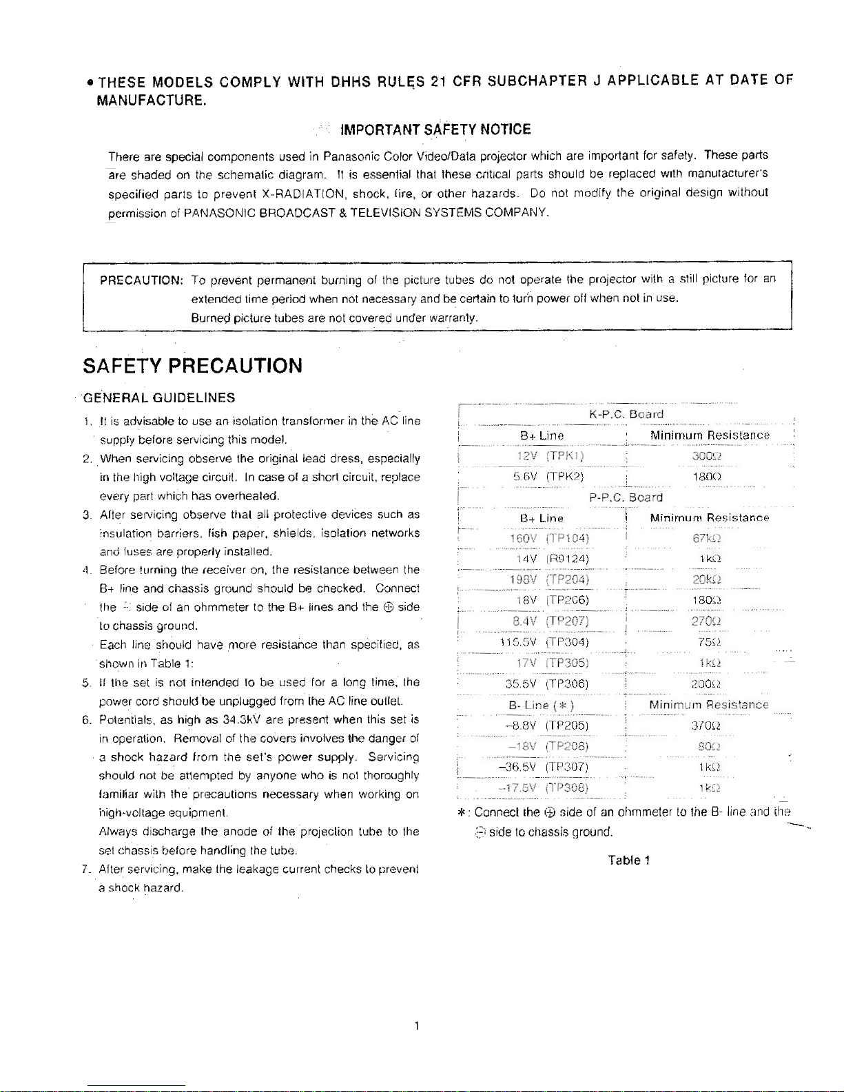
'1, Beiore turning the receiver on, the resistance between the
B+ line and chassis ground should be checked. Coonect
the :. side of an ohmmeter to the B+ lines and the (B side
, ,
10 chassis ground.
Each line' should have more resistance than specified, as
'shown in Table 1:
5 Ir the set is not intended to be used ror a long time: the
power cord Should be unplugged from ihe AC line outlet.
6. Potentials. as high as 34.3kV are present when this set is
in operation. Removal of the covers involves the danger or
. a shock hazard rrom the set's power supply. Servicing
should not be attempted by anyone who is not thoroughly
familiar with the precautions necessary when working on
higll-voliage equipment
Always discharge the anode of theprojeclion tube to the
sel chassi.s before handling the tube. .
7 - . Alter servicing, make the leakage current checks 10 prevent
a shock hazard.
IMPORTANT SAFETY NOTICE
.....
,
~
* : Connect the (f) side or an ohmmeter to the B- Ijne and the
.:~:I side to (;hassls ground. --"
Table 1
1
LEAKAGE CURRENT COLD CHECK
1. Unplug the AC cord and connect a jumper between the two
plug prongs.
Turn on the set.
Measure the resistance value with an ohmmeter between
the jumpered AC plug and each exposed metallic part such
as screwheads, inpullerminals, control shafts, etc.
. When the exposed metallic part has. a return path to the
chassis. the reading should be between 490~2 and 9M!1.
3.
When Ihe exposed melal does not have a return path to
the chassis. the reading must be infinite. .
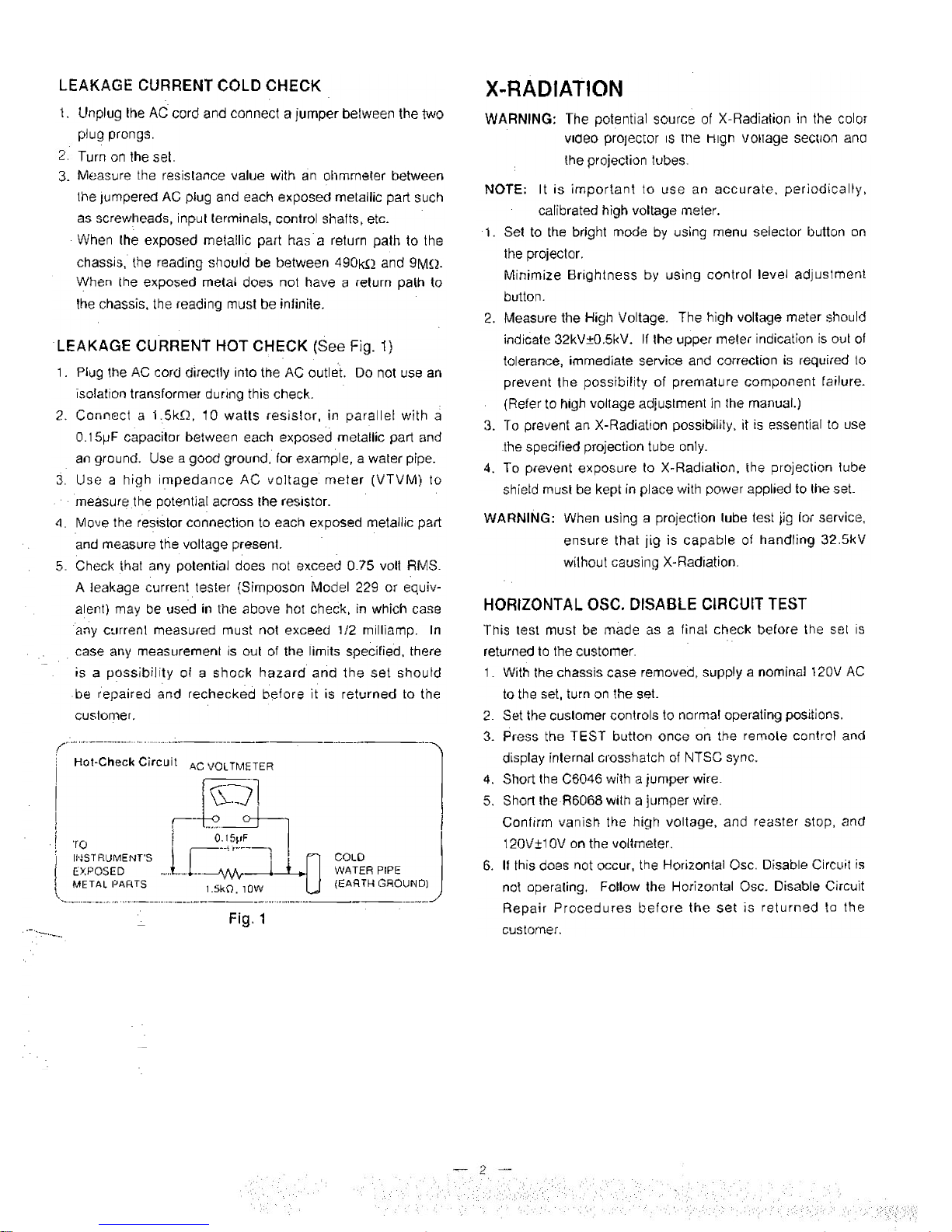
LEAKAGE CURRENt HOT CHECK (See Fig. 1)
1. Plug the AC cord directly into the AC outlet. Do not use an
isolation transformer during this check.
2. Connect a L5k!2, 10 watts resistor, in parallel with a
O. 15~F capacitor between each exposed metallic part and
an ground. Use a good ground, for example, a water pipe.
3. Use a Iligh impedance AC voltage meter (VTVM) to
measurelhe potential across the resistor.
4. Move the resistor connection to each exposed metallic part
. .
and measure the. voltage present. '.
5. Check .that any potential does not exceed 0.75 vol! RMS.
. ..
A leakage current tester (Simposon Model 229 or equiv-
alent) may be used in the above hot check, in which case
any currenl measured must not exceed 1/2 milliamp. In
. case any measurement is out of Ihe iimits specified. there
is a possibility of a shock hazard arid the set should
be repaired and rechecked before it is returned to the
customer.
~~
r-'--"-'-'
; Hot-Check Circuit AC VOLTMETER
(i.-:J
I
I
1 O.15~F . t TO COL.D
j INSTRUMENT'S WATER PIPE
l EXPOSED l_.~ (EARTH GROUNO)
METAL PIIRTS 1.5110. lOW
. -.-
Fig. 1
Fig. 1
.-~.
~~~
X-RADIATION
WARNING: The potential source of X-Radiation in the color
video projector is the High voltage section and
the projection lubes.
NOTE: It is important to use an accurate, periodically,
calibrated high voltage meter.
1. Set to the bright mode by using menu selector button on
the projector.
Minimize Brightness by using control level adjustment
button.
2. Measure the High Voltage. The high voltage meter should
indiCate 32kV:!:O.5kV. If the upper meter indication is oul of
tolerance, immediate service and correction is required to
prevent the possibility of premature component railure.
(Refer to high voltage adjustment in the manual.)
3. To prevent an X-Radiation possibility, it is essential to use
the specified projection tube only.
4. To prevent exposure to X-Radiation, the projection tube
shield must be kept in place with power applied to the set.
WARNING: When using a projection tube test jig lOt service,
ensure that jig is capable of handling 32.5kV
without causing X-Radiation.
HORIZONTAL OSC. DISABLE CIRCUIT TEST
This test must be made as a final check before the set is
returned to the customer. .
1. With the chassis case removed. supply a nominal 120V AC
to the set, turn on the set.
2. Set the customer controls to normal operating positions.
3. Press the TEST button once on the remole control and
display Internal crosshatch of NTSC sync.
4. Short the C6046 with a jumper wire.
5. Short theA6068 wilh a jumper wire.
Confirm vanish the high voltage. and reaster stop. and
120V:t10V on the voltmeter.
6. If this does not occur, the Horizontal Ose. Disable Circuit is
nol operating. Follow the Horizontal Ose. Disable Circuit
Repair Procedures before the set is returned 10 the
customer.
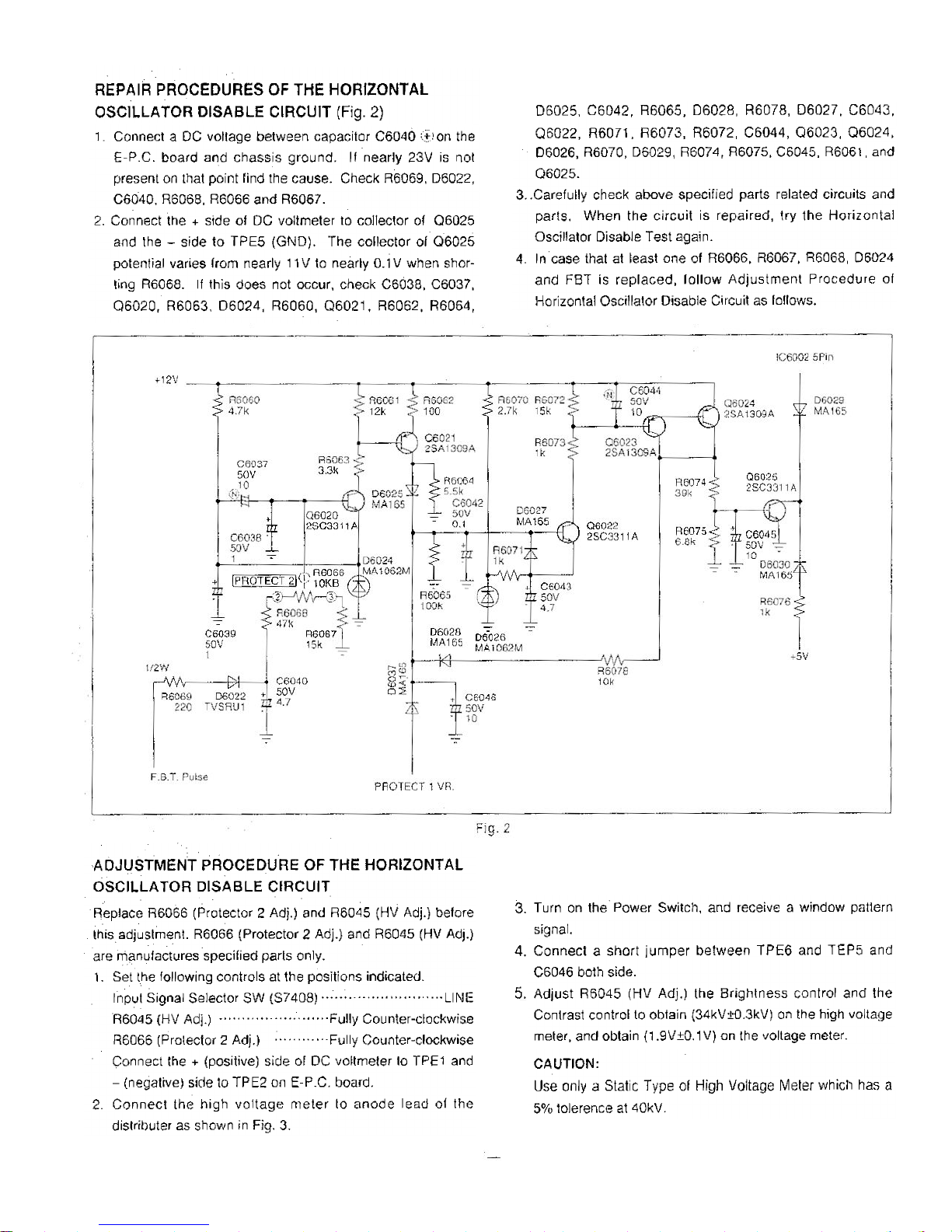
REPAIR PROCEDURES OF THE HORIZONTAL
OSCILLATOR DISABLE CIRCUIT (Fig. 2)
1. Connect a DC vOltage between capacitor C604Q ::t) on the
E-P.C. board and chass.is ground. If nearly 23V is not
present on that point find the cause. Check R6069. D6022,
C6040, R6D68, R6D66 and R6067,
2. Connect the + side 01 DC voltmeter to collector of 06025
and the - side to TPE5 (GND). The collector of 06025
potential varies Irom nearly 11 V \0 nearly 0.1 V when shor-
ling R6D68. If this does not occur, check C6038, C6037 ,
Q6020, R6063. 06024, R6060, Q6021 , R6062, R6064,
.ADJUSTMENT PROCEDURE OF THE HORIZONTAL
OSCILLATOR DISABLE CIRCUIT
. .. .
Replace R6066 (Protector 2 Adj.) and R6045 (HV Adj.) before
. .
this adjustment. R6066 (Protector 2 Adj.) and R6045 (HV Adj.)
are in~nulactures specified parts only.
1. 8et the following controls at the positions indicated.
Input Signal Selector SW (87408) LlNE
R6045 (HV Adj.) """"""""""""Fully Counter-clockwise
R6066 (Pro/ector 2 Adj.) """"""Fully Counter-clockwise
Connect the + (positive) side or DC voltmeter to TPE1 and
- (negalive) side to TPE2 on E-P.C. board.
2. Connect the high voltage meter to anode lead of the
distributer as shown in Fig. 3.
06025. C6042. R6065. 06028, R6078. 06027. C6043.
Q6022. R6071. R6073. R6072, C6044. Q6023, Q6024.
. D6026. R6D70. D6O29, R6074.R6075,C6045. R6061,and
Q6025.
3. .Carefully check above specified parts related circuits and
parIs. When the circuit is repaired. try 1he Horizontal
Oscillator Disable Test again.
4. In case that at least one of R6066, R6067, R6068, D6024
and FBT is replaced. follow Adjustment Procedure of
Horizontal Oscillator Disable Circuit as follows.
Turn on the Power Switch. and receive a window pattern
signal.
Connect a short jumper between TPE6 and TEPS and
C6046 both side.
Adjust R6045 (HV Adj.) the Brightness control and the
Contrast control to obtain (34kV:tO.3kV) on the high voltage
meier, and obtain (1 .9V.:!:O.1V) on the voltage meter.
3.
4.
5.
CA UTION:
Use only a Stalic Type 01 High Voltage MeIer whicJ1 has a
5% tolerence at 40kV-

Adjust R6066 (Protector 2 Adj.) slowly clockwise unit shut-
6.
down occurs and hold that position.
7. Turn oilihe power switch.
B. Adjust R6045 (HV Adj.) slightly counler-elockwise.
9.
Turn on the power switch.
10. Adjust R6045 (HV Adj.) slowly clockwise until shut-down
occurs High VoHage should be 34kV:!:O.5kV, and 1.9V
t.O.1 V on the voltage meter just before shut-down.
, 1. " the readings in step 10 are not confirmed. repeat steps
5 to 10.
Turn ofl the power SWItch.
13. Disconnect the short jumper between TPE6 and TPE5.
and C6046 both sides.
Turn on the 'power switch, and adjust (hal the high voltage
is 32.0kV:!:O.5kV with R6045.
15: Confirm that the high voltage does not ctiange by iurnlng
. .' the Brightnessand Contrast controls.
16. Fix R6066 (Protector 2 Adj.) and R6045 (HV Adj.) with
.' .
bond as illustrated below. (Fig. 4)
Fig. 4
tt;~!';:t;;;'- : 5'/,;<" "'~:
X-RAY PRECAUTIONS
The Iront area (between the projection tube and the lens.) is
enclosed by a metal box to ensure positive safety during
abnormal and normal conditions when checkinQ and doing
repair work. To fully ensure safety, however. the following
precautions must be observed.
(1) Do not remove the lens.
(2} Be sure to lurn OFF the power when the lens must be
removed and when yO~t could be exposed \0 X.rays
during cleaning and other routine servicing.
(3) Do not remove the lens to check the projection tube for
operation by watching it directly.
(4) Do not remove Ihe LEAD TAPE on the CRTs. (Fig. 5)
(5) Do not remove the METAL COVEA on the CATs. (Fig. 5)
(6) Do not remove the LEAD TAPE LENSes. (Fig. 5)
Fig. 5
~
RCUJT EXPLANATIONCI
~
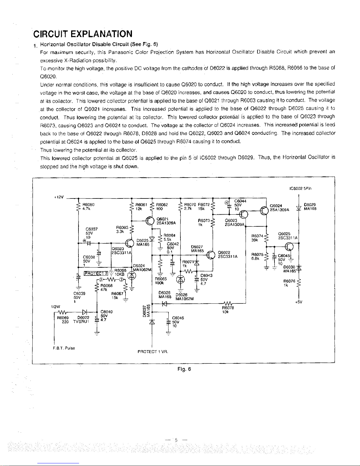
Horizontal Oscillator Disabie Circuit (See Fig. 6)
For maximum security, this Panasonic Color Projection System has Horizontal Oscillator Disable Circuit which prevent an
excessive X-Radiation possibility. .
To monitor the high voltage. the positive DC voltage Irom the cathodes of 06022 is applied through R6D68, R6D66 to the base of
06020.. ..
Under normal conditions, this voltage is insufficient to cause 06020 to conduct. If the high voltage increases over the specified
voltage in the worst case, the voltage at the base of 06020 increases, and causes Q6020 to conduct. thus lowering the potential
at its collector. This lowered collector potential is applied to the base of 06021 through R6063 causing it to conduct. The voltage
al the collector of 06021 increases. This increased potential is applied to the base of 06022 through 06025 causing it to
conduct. Thus lowering the potential at its collector. This lowered Collector potential is applied to the base 01 06023 through
R6073. causing Q6023 and 06024 to conduct. The voltage at the collector of Q6024 increases. . This increased potential isleed
back to the base of Q6022 through R6078, 06028 and hold the 06022,06023 and 06024 conducting. The increased collector
--. --.:-. -> ""<on,., A ,- ---"--' .- k__- _I ,."",n,.,.c: 11 .~... co:!n7 A --. ,_I_~ H In n~ft"" ""I
~~~~
potential at 06024 is applied to the base 01 06025 through R6074 causing ilto conduct.
Thus lowering the potential at its collector. . .
. This lowered collector potential at 06025 is applied to the pin 5 'of IC6002 through 06029.
stopped and the high voltage is shut down. '.
~
IC6002 SPIn
+12V
~ C8044
R6O6O A6070 A6072 ~ty 5OV 06029
4.7k Vie 15k 10 MA1S5
A6073
1k
C6037
50V
10
iif;
C6O2O
25C3311 ~2
2SC3311A
C~39 D6028 D(rO26 ~
I5OV MA165 MAI062M
1 -=- +5V
112W {:):g R6O78
g< ,~
R6069 D6022 0 ~ ,. C6046
220 TVSRU1 5OV
. 10
- -
- -
F.B.T. Pulse PROTECT 1 VA.
Fig. 6
~~~~~~~~~~~~
The increased collector
Thus, the Horizontal Oscillator is
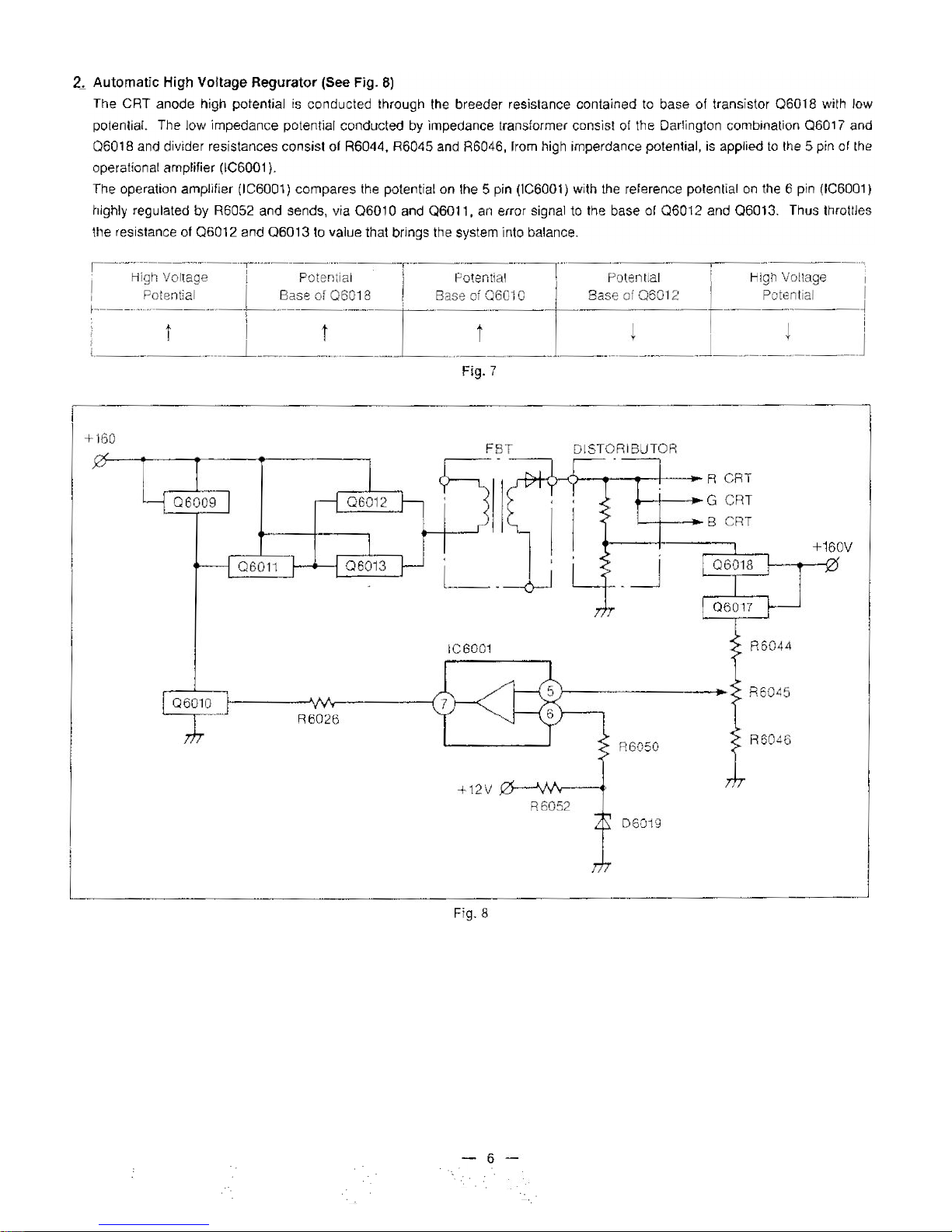
Automatic High Voltage Regurator (See Fig. 8)
The CRT anode high potential is conducted through the breeder resistance contained to base of transistor Q6018 with Jow
potentiaL The Jow impedance potential conducted by impedance transformer consist of the Darlington combination Q6017 and
Q6018 and divider resistances consist of R6044. R6045 and R6046, from high imperdance potential, is applied to Ihe 5 pin of the
operational amplifier (lC6001).
The operation amplifier (lC6001) compares the potential on the 5 pin (IC6001) with the reference potential on the 6 pin (IC6DD1}
highly regulated by R6052 and sends, via Q6010 and Q6011, an error signal to the base of Q6012 and 06013. Thus throttles
the resistance of Q6012 and 06013 to value that brings the system into balance.
2.
~~~
. 6-
~~~~~
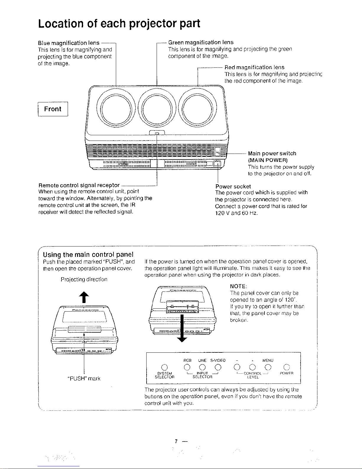
Location of each projector part
When using the remote control unit, poinl
toward the window. Alternately, by pointing the
remote control unit at the screen, the IR
receiver will detect the reflected signal.
~~
The power cord which is supplied with
the projector is connected here.
Connecl a power cord thai is raled for
120 V and 60 Hz.
7
~~~~~~~
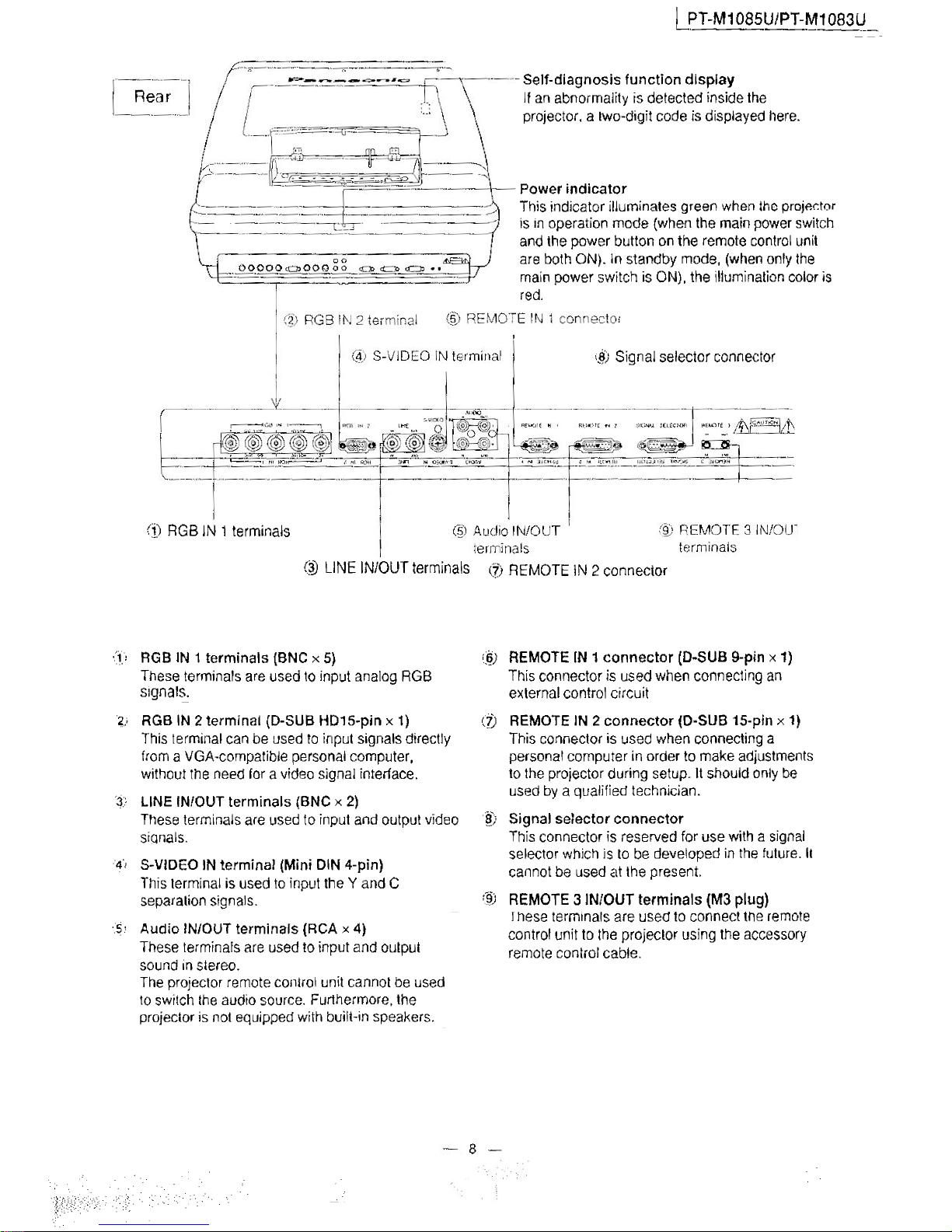
(j) AGB IN 1 terminals
-'1' RGB IN 1 terminals (BNC x 5)
These terminals are used to input analog RGB
signals.
2.) RGB IN 2 terminal (D-SUB HD15-pin x 1)
This terminal can be used to input signals directly
from a VGA-compatible personal computer,
without the need for a video signal interface.
~: LINE IN/OUT terminals (BNC x 2)
These terminals are used 10 input and output video
siQnals.
4" S-VIDEO IN terminal (Mini DIN 4-pin)
This terminal is used to input the Y and C
separation signals.
'5' Audio IN/OUT terminals (RCA x 4)
These terminals are used to input and output
sound in stereo.
The projector remote control unit cannot be used
\0 switch the audio source. Furthermore. the
projector is not equipped with built.in speakers.
:'. . " '"
. . ' .
'}~iiri{'l:'; :~~';ii:: " ::,..: :~' :',
~~
U>T-M1085U1PT-M1083U
Self-diagnosis function display
If an abnormality is detected inside the
projector, a Iwo-digit code is displayed here.
Power indicator
This indicator illuminates green when tho proj~tor
is in operation mode (when the main power switch
and the power button on the remote control unit
are both ON). In standby mode. (when only the
main power switch is ON). the illumination color is
red.
I§) Signal selector connector
(I) REMOTE IN 2 connector
@ LINE IN/OUT terminals
@
REMOTE IN 1 connector (D-SUB 9-pln x 1)
This connector is used when connecting an
exlernal control circuit.
ev
REMOTE IN 2 connector (D-SUB 15-pin x 1~
This connector is used when connecting a
personal computer in order to make adjustments
to the projector during setup- It should only be
used by a qualified technician.
Signal selector connector
This connector is reserved for use with a signal
selector which is to be developed in the future. \I
cannot be used at Ihe present.
ID
@
REMOTE 3 IN/OUT terminals (M3 plug)
These terminals are used to connect the remote
control unit to the projector using the accessory
remote control cable.
8
~~~
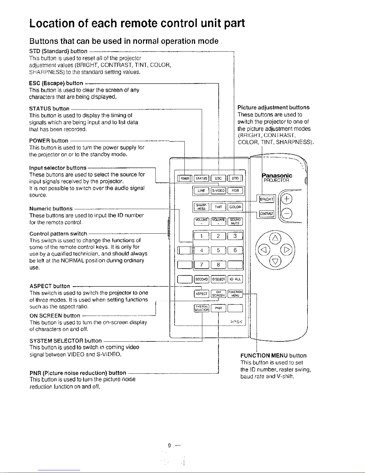
Location of each remote control unit part
ESC (Escape) button --
This button is used to clear the screen of any
characters that are being displayed.
STATUS button ---
IThis button is used 10 display the timing of
signals which are being input and to list data
that has been recorded.
POWER button" ..-.....---..-
This button is used to turn the power supply for
the projector on or to the standby mode.
Input selector buttons L
These buttons are used to select the source for
input signals received by the projector.
It is not possible to switch over the audio signal
source"
Numeric buttons --.---..
These buttons are used 10 input the ID number
Ifor the remote control. -
Control pattern switch "_'_00""'" -;
This switch is used to change the functions of
some of the remote control keys" It is only for
use by a qualified technician, and should always
be left al the NORMAL position during ordinary
use.
ASPECT button
This switch is used to switch the projector to one
of three modes. II is used when setting functions
Isuch as the aspect ralio"
ON SCREEN button oo ,,---J
This button is used to turn the on-screen display
of characlers on and off.
SYSTEM SELECTOR button ......-.-..............-
signal between VIDEO and S-VIDEO. I
PNR (Picture noise reducUon) button - .J
This button is used to swilch in coming video
This button is used to lurn the picture noise
reduclion function on and off.
Picture adjustment buttons
These buttons are used to
switch the projector to one of
the picture adiustment modes
I
FUNCTION MENU button
This button is used to set
the 10 number, raster swing,
baud rate and V-shift.
9
~
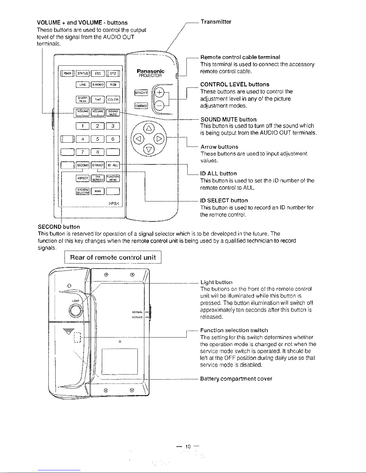
VOLUME + and VOLUME - buttons
These buttons are used to control the output
level of the signal from the AUDIO OUT
I
SECOND button
This button is reserved lor operation of a signal selector which IS to be developed in the future. The
function ollhis key changes when the remole control unit is being used by a qualJfied technician to record
signals.
Remote control cable terminal
This terminal is used to connect the accessory
remote control cable.
CONTROL LEVEL buttons
These buttons are used to control the
adjustment level in any of the picture
adjustment modes.
This button is used to turn off the sound which
is being output from the AUDIO OUT terminals.
ID ALL button
This button is used to set the 10 number of the
remote control to ALL.
ID SELECT button
This button is used to record an 10 number for
the remote control.
10
-
~~~~~
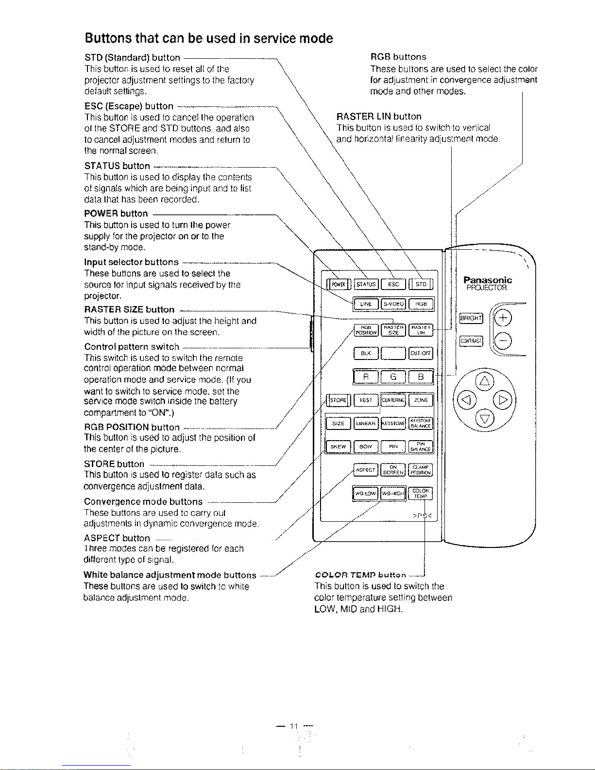
Buttons that can be used in service mode
POWER button ~This button is used to turn the power
supply for the projector Dn Dr tD Ihe
stand-by mode.
Input selector buttons -'-'-"-"'--' '-"'",-
These buttons are used to select the ~
source for input signals received by the
proj ector.
RASTER SIZE button
This button is used to adjust the height and
width of the picture on the screen.
control operation mode between normal
operation mode and service mode. (If you
want to switch to seNice mode. set Ihe
service mode switch inside the battery
compartment to "ON".)
This butlon is used to adjust the position 01
the center of the picture.
This button is used to register dala such as
convergence adjustment data.
Three modes can be registered for each '"
different type of signal.
/White balance adjustment mode buttons -.----
These bullons are used to switch to white
balance adjustmenl mode.
~
RGB buttons
These buttons are used to select the color
ror adjustment In convergence adjustment
mode and other modes.
"' "" , 1 . " .."'.,
This button is used to switch the
color temperature setting belween
LOW, MID and HIGH.
~~~~~
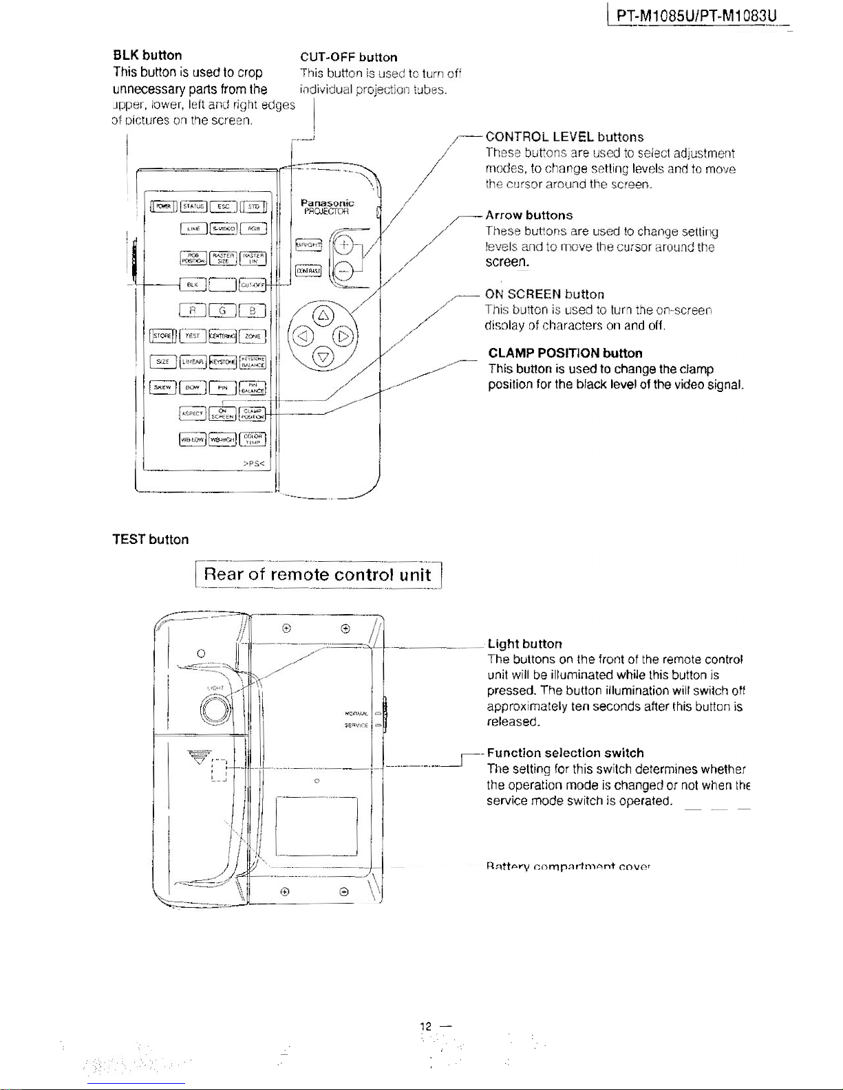
BlK button
This button is used to crop
unnecessary parts from the
TEST button
~
I PT-M1085U1PT-M1083U
screen.
'" CLAMP POSITION button
~ This button is used to change the clamp
~ position for the black level of the video signal.
)1 unit I
Light button
The buttons on the front of the remote control
unit will be illuminated while this button is
I pressed. The button illumination will switch off
approximately ten seconds after this button is
released.
~ Function selection switch
-. TIle setting for this switch determines whether
the operation mode is changed or not when the
service mode switch is operated.
12 -
I
~~~~~~
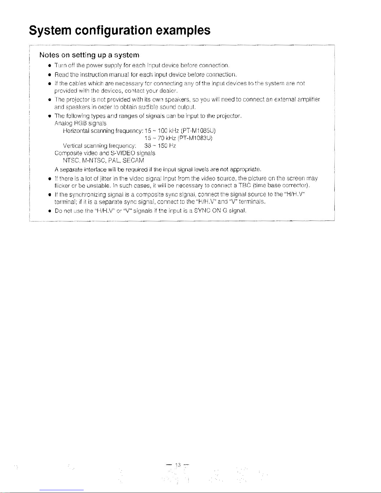
System configuration examples
~~~~~~~~~
PT.M1085U1PT-M1083U I
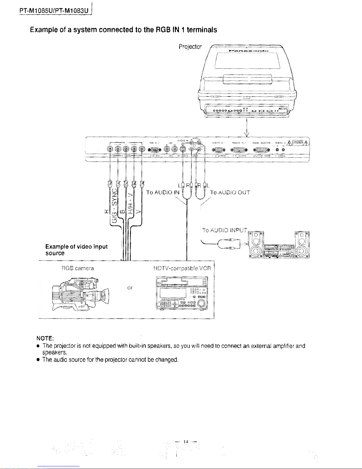
Example of a system connected to the RGB IN 1 terminals
Example of video input
source
NOTE:
. The projector is nol equipped with built-in speakers, so you will need to connect an external amplifier and
speakers.
The audio source for the projector cannot be changed.
.
~~~~~~
Projector
~~i~
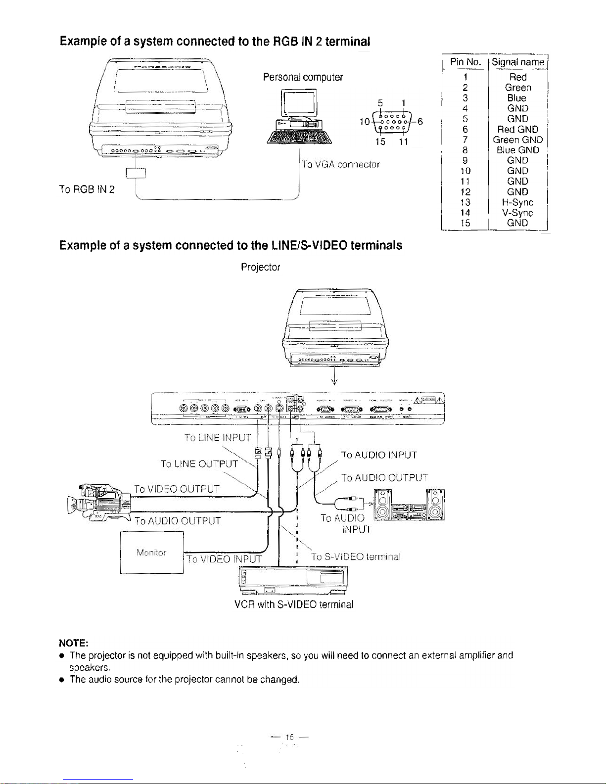
Example of a system connected to the RGB IN 2 terminal
ToRGBIN2
Example of a system connected to the LlNE/5-VIDEO terminals
NOTE:
. The projector is not equipped with built-in speakers, so you will need to connect an external amplifier and
speakers.
. The audio source for the projector cannot be changed.
Pin1N~.- Sign:~a~~-
12 Green
3 Blue
I4 GND
5 GND!
6 Red GND
I7 Green GND
8 Blue GND :
9 GND I
10 GNO
11 GND
12 GND
13 H-Sync
14 V-Sync
15 GND
Personal computer
& 10 5 1
Projector
VCR with S-VIDEO terminal
~~
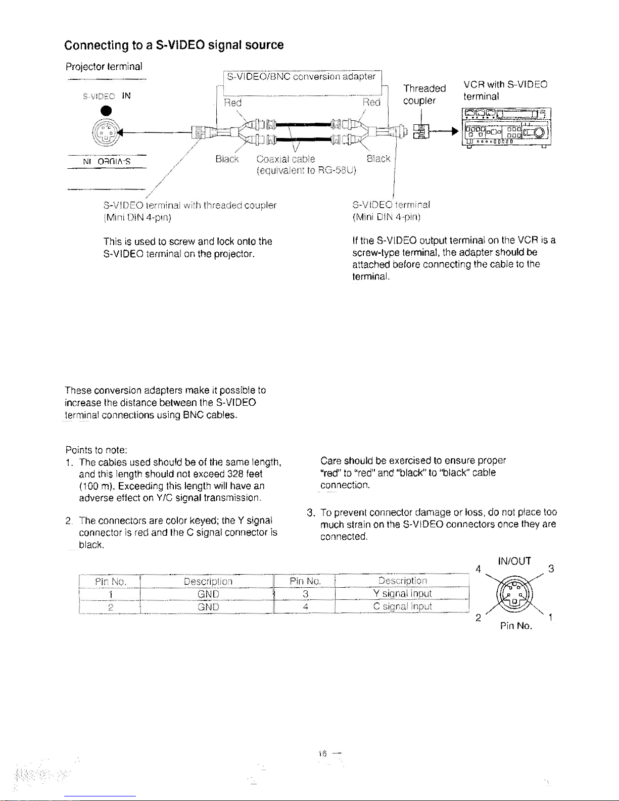
Connecting to a S-VIDEO signal source
Projector terminal
IN
NI 0=1011\0£
This is used to screw and lock onto the
S.vIDEO terminal on the projector.
These converSion adapters make it possible to
increase the distance between the S-VIDEO
terminal connections using BNC cables.
Points to note:
1. The cables used should be of the same length.
and this length should not exceed 328 feet
(100 m). Exceeding this length will have an
adverse effect on Y/C signal transmission.
2. The connectors are color keyed; the Y signal
connector IS red and the C signal connector IS
black.
~
VCR with S-VIDEO
terminal
If the S-VIDEO output terminal on the VCR is a
screw-type terminal. the adapter should be
attached before connecting the cable to the
terminal.
Care should be exercised to ensure proper
"red" to "red" and "black" to "black" cable
connection.
To prevent connector damage or loss, do not pi ace too
much strain on the S-VIDEO connectors once they are
connected.
3.
IN/OUT
4
-
3
1
.:0:
2 Pin No.
~~~
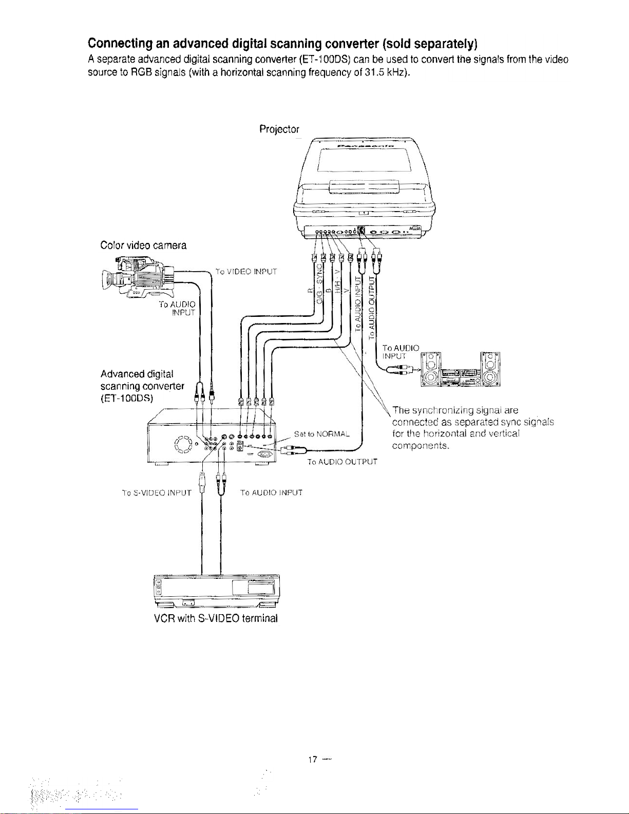
Connecting an advanced digital scanning converter (sold separately)
A separate advanced digital scanning converter (ET-100DS) can be used to convert the signals from the video
source to RGB signals (with a horizontal scanning frequency of 31.5 kHz).
Color video camera
Advanced digital
scanning converter
(ET-100DS)
VCR with S-VIDEO terminal
. .
, ,", "
", ,
"!.~'~'}'::}<": ...;1:"> :' ."':. :
Projector
17
'.
~
PT-M1085U1PT-M1083U I
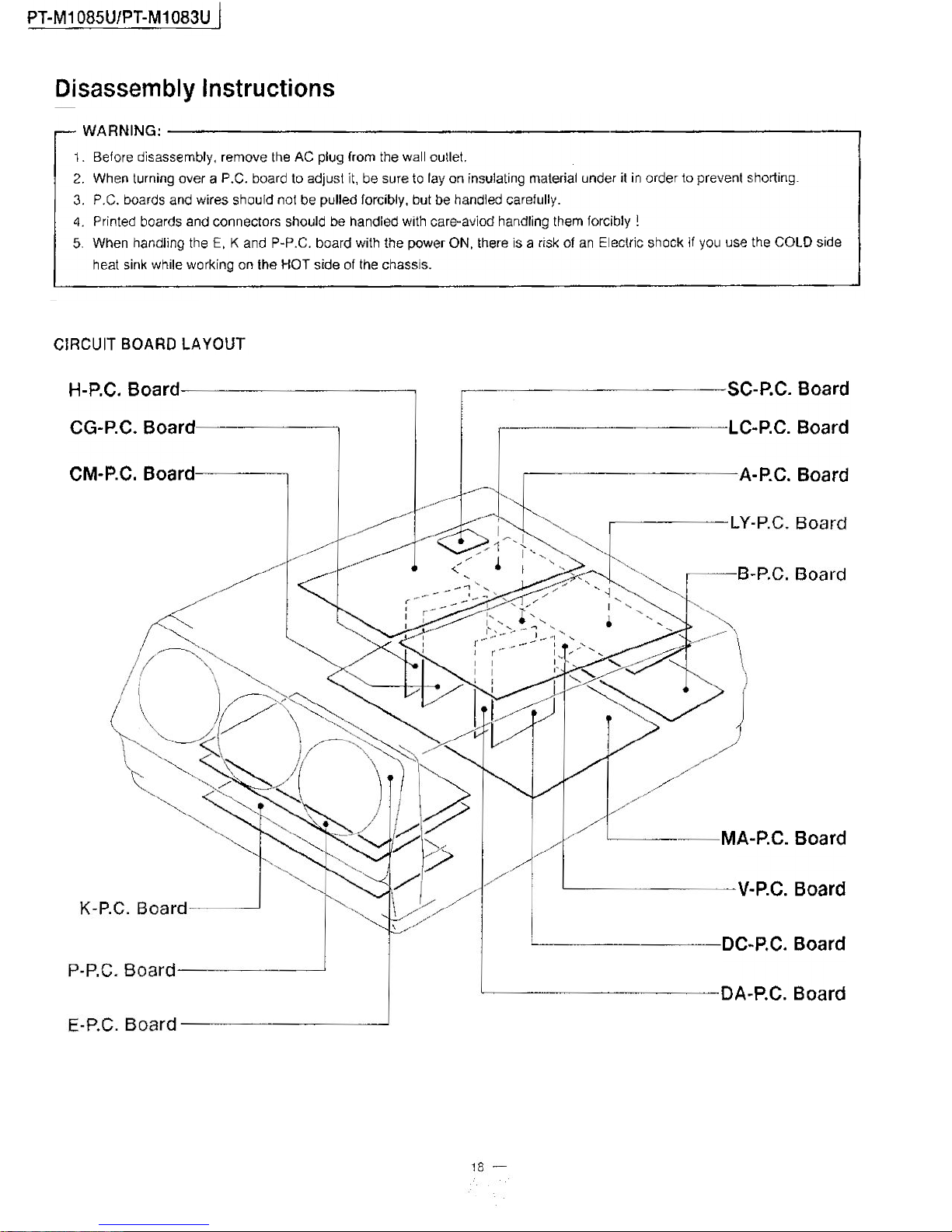
Disassembly Instructions
WARNING:
1. Before disassembly. ramove the AC plug from the wall oullet.
2. When turning over a P.C. board to adjust it. be sure to lay on insulating material under it in order to prevent shorting.
3. P.C. boards and wires should not be pulled forcibly, but be handled carefully.
4. Printed boards and connectors should be handled with care-aviod handling them forcibly!
5. When handling the E, K and P-P.C. board with the power ON. there is a risk of an Electric shock if you use the COLD side
heat sink while working on the HOT side of the chassis.
CIRCUIT BOARD LAYOUT
H-P.C. Board-
CG-P.C. Board
CM-P.C. Board
.SC-P.C. Board
-LC-P.C. Board
-A-P.C. Board
MA-P.C. Board
- V-P.C. Board
'DC~P.C. Board
DA.P.C. Board
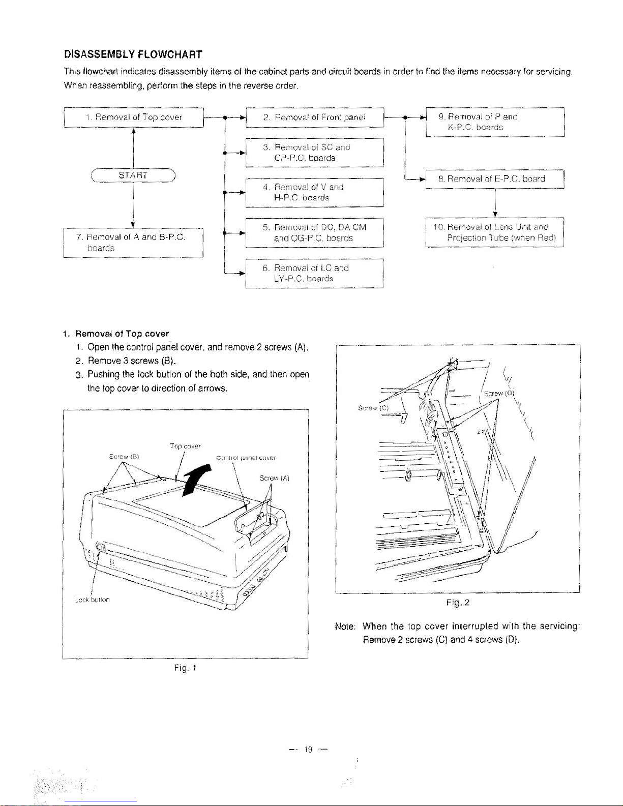
DISASSEMBLY FLOWCHART
This flowchart indicates disassembly items of the cabinet parts and circuit boards in order to find the items necessary for servicing.
When reassembling. perform the steps in the reverse order.
1. Removal of Top cover
Open the control panel cover, and remove 2 screws (A).
1.
2.
3.
Remove 3 screws (8).
Pushing the lock button of the both side. and then open
the top cover 10 direction of arrows.
Note: When the top cover interrupted with the servicing;
Remove 2 screws (C) and 4 screws (D).
;
~
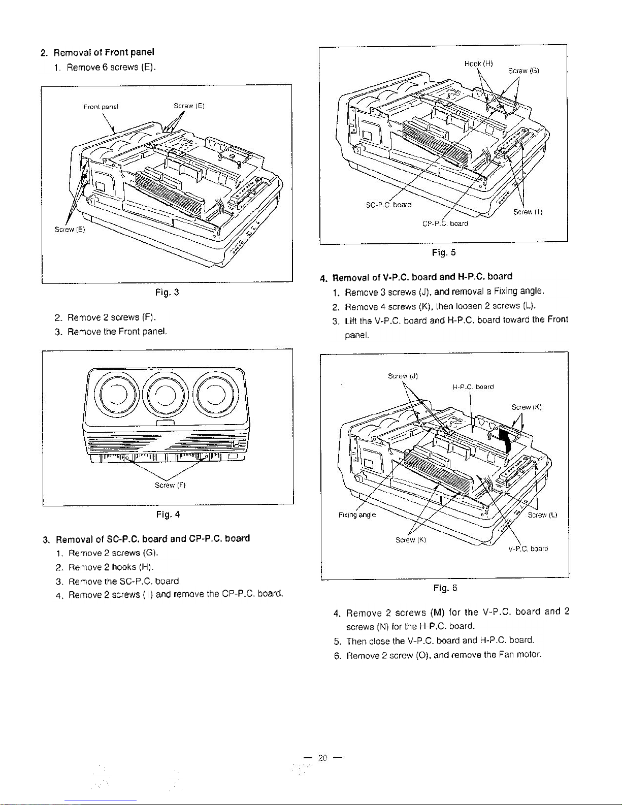
2. Removal of Front panel
1. Remove 6 screws (E).
Remove 2 screws (F).
Remove the Front panel.
2.
3.
3. Removal of SC-P.C. board and CP-P.C. board
Remove 2 screws (G).
Remove 2 hooks (H).
Remove the SC-P.C. board.
1.
2.
3.
4.
Remove 2 screws {I} and remove the CP-P.C. board.
~~
4.
Removal of V-P.C. board and H-P.C. board
1. Remove 3 screws (J). and removal a Fixing angle.
2. Remove 4 screws (K). then loosen 2 screws (L).
3. Lilt the V-P.C. board and H-P.C. board toward the Front
panel.
4. Remove 2 screws (M) fo r the V -P. C. board and 2
screws (N) lor the H-P.Co board.
Then close the V-PoCo board and H-P.Co board.
Remove 2 screw (0), and remove the Fan motor.
5.
6.
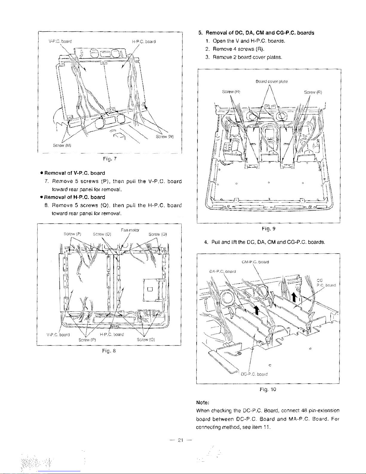
. Removal of V.P.C. board
7. Remove 5 screws (P). then pull the V-P .C. board
toward rear panel for removal.
. Removal of H-P.C. board
8. Remove 5 screws (Q), then pull the H-P.C. board
toward rear panel ror removal.
~
:~W~~~:>1,~,~, "",l'
",
5. Removal of DC, DA, CM and CG-P .C. boards
1. Open the V and H-P.C. boards.
2. Remove 4 screws (R).
3. Remove 2 board cover plates.
4. Pull and Uft the DC. DA. CM and CG-P.C. boards.
Note:
When checking the DC-P .C. Board. connect 48 pin-extension
board between DC-P,C. Board and MA-P.C. Board. For
connecting method, see item 11.
~~~~~
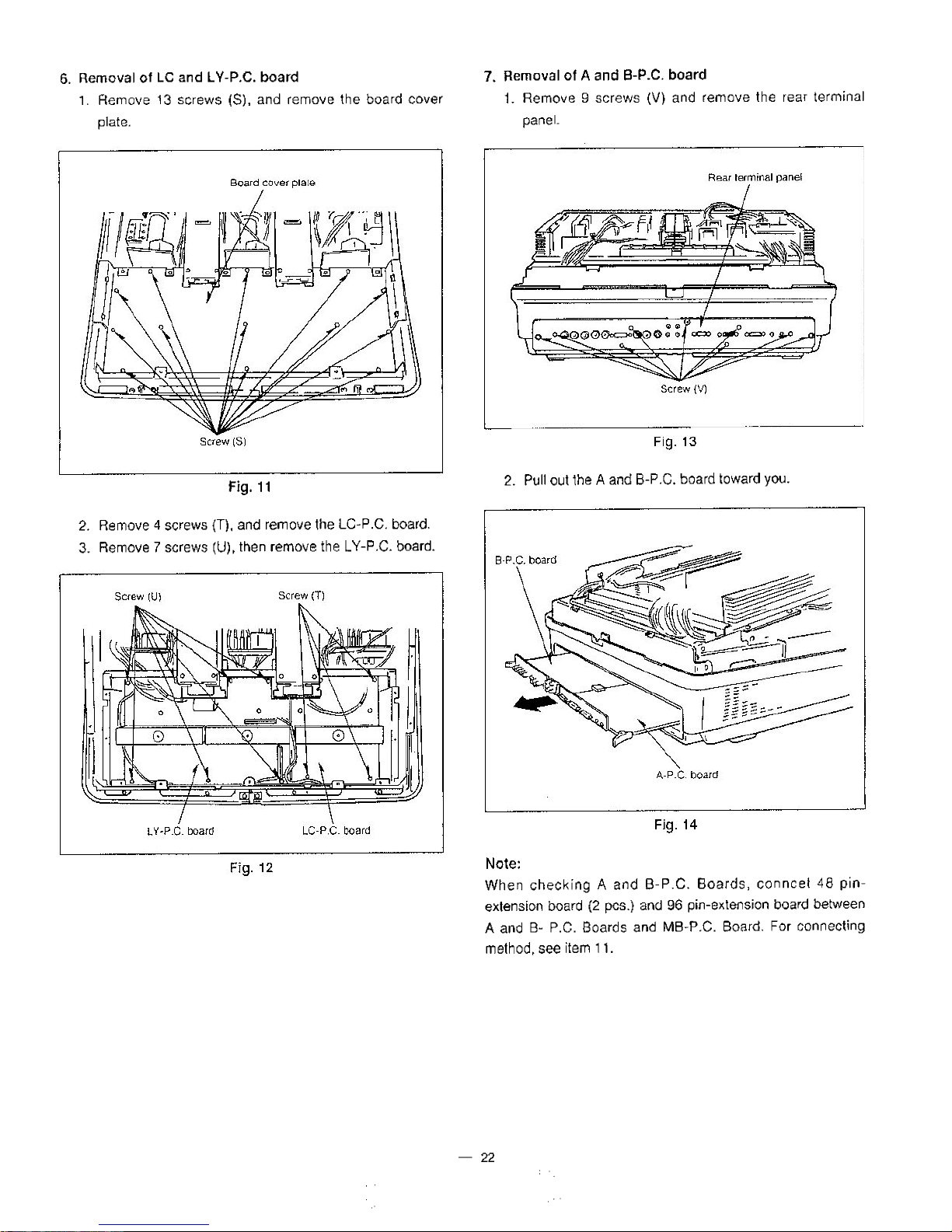
Removal of LC and L V-P.C. board
,. Remove 13 screws (5), and remove the board cover
plate.
6.
Fig. 11 2. Pu 11 out the A and B-P. C. board toward you.
2. Remove 4 screws (T). and remove the LC-P.C. board.
3. Remove 7 screws (U), then remove the L Y-P.C. board.
Removal of A and B-P.C. board
1. Remove 9 screws (V) and remove the rear terminal
paneL
7.
Note:
When checking A and B-P .C. Boards, conncel 48 pin-
extension board (2 pes.) and 96 pin-extension board between
A and B- PoCo Boards and MB-P.Co Board. For connecting
method, see item 11.
- 22
~~~~
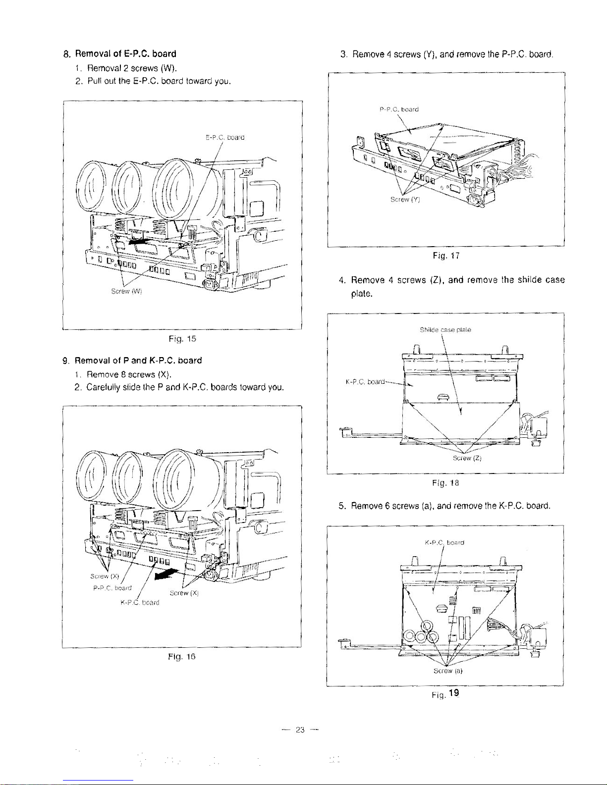
8.
Removal of E-P.C. board
1. Removal 2 screws (W).
Pull out the E-P.C. board toward you.2.
9.
Removal of P and K-P.C. board
1. Remove 8 screws (X).
Carefully slide the P and K.P.C. boards toward you.2-
~~~
Remove 4 screws (V), and remove the P-P.C. board.
3.
4. Remove 4 screws (2). and remove the shilde case
plate.
Remove 6 screws (a). and remove the K-P .C. board.5.
19
~~~~~~
~T.M1085U1PT.M1083U I
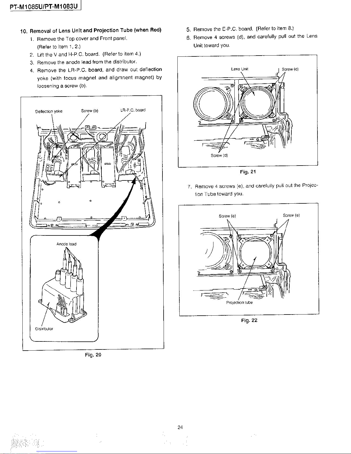
Removal of Lens Unit and Projection Tube (when Red)
1. Remove the Top cover and Front panel.
(Refer to Item 1,2.)
2. Lift the V and H-P.C. board. (Refer to item 4.)
3. Remove the anode lead from the distributor.
4. Remove the LR-P.C. board, and draw out deflection
yoke (with focus magnet and aligmnent magnet) by
loosening a screw (b).
10.
~~~
Remove the E-P.C. board. (Refer to item 8.)
Remove 4 screws (d). and carefully pun out the Lens
Unit toward you.
5.
6.
24
~~~~~
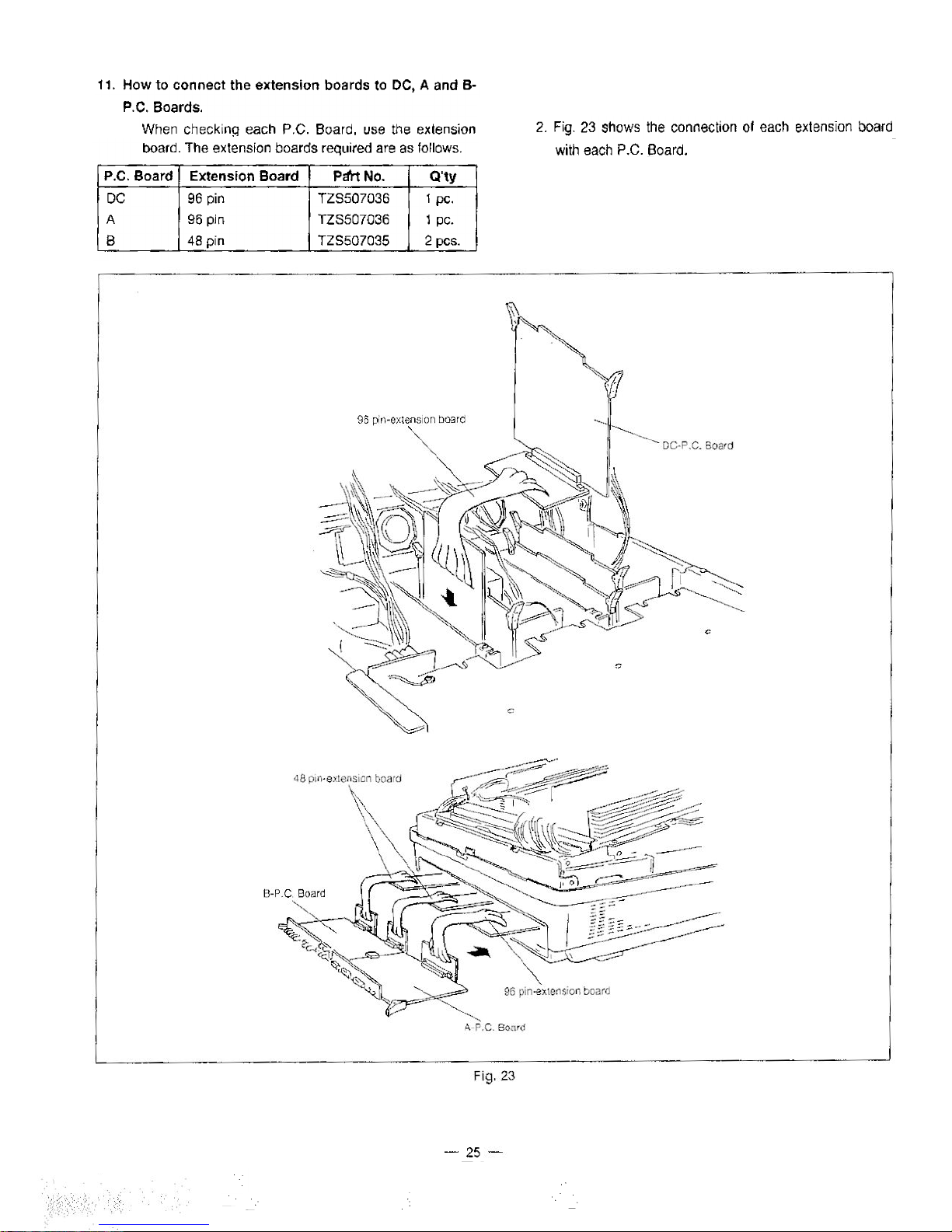
11. How to connect the extension boards to DC, A and BP.C. Boards.
1. When checking each P .C. Board, use the extension
board. The extension boards required are as fonows.
P.C, Board Extension Board pm No. Q'ty
DC 96 pin TZS5Q7036 1 pc.
A 96 pIn TZSSO7036 1 pc.
B 48 pin TZS507035 2 pes.
~~
23 shows the connection 01 each extension board
2. Fig. 23 shows the cor
with each P.C. Board.
25
~~~~
PT.M1085U/PT-M1083U I
~
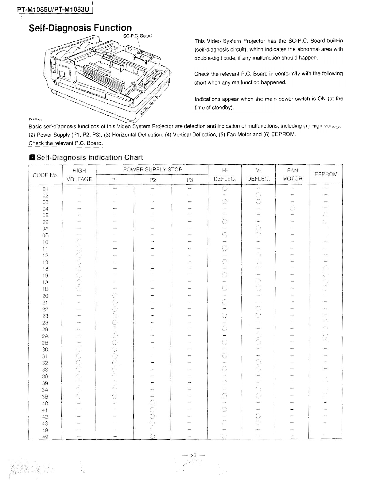
Self-Diagnosis Function
~ SC.P.q. Board
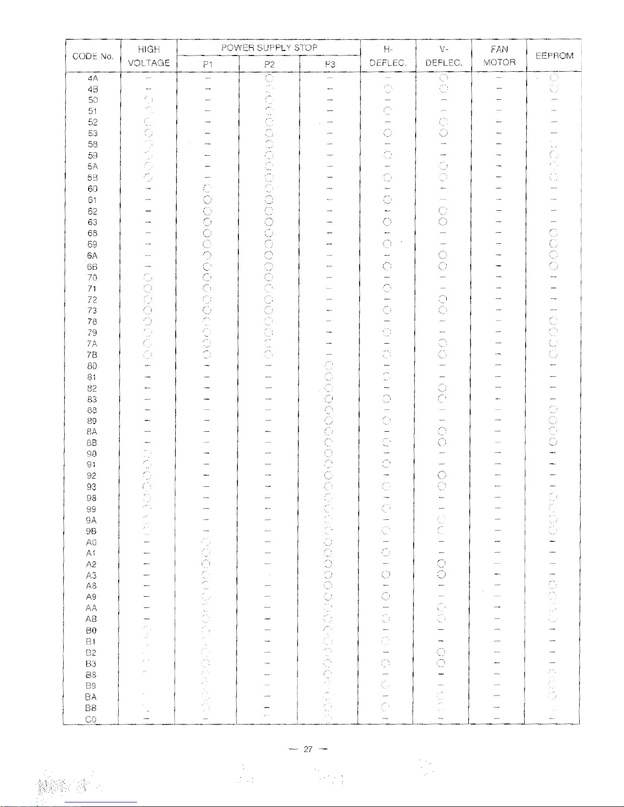
Basic self-diagnosis functions of this Video System Projector are detection and indication 01 malflln~tions, includillg (1) Iligh Voltage,
(2) Power Supply (P1, P2, P3), (3) Horizontal Deflection, (4) Vertical Deflection, (5) Fan Motor and (6) EEPROM.
Check the relevant P.C. Board.
~~
This Video System Projector has the SC-P.C. Board built-in
(self-diagnosls circuit), which indicates the abnormal area with
double-digit code, if any malfunction should happen.
Check the relevant P.C. Board in conformity with the following
chart when any malfunction happened.
Indications appear when the main power switch is ON (at the
time of standby).
~~~~~
, ~!0.):y{; :,' ' i:,;t
~~~~~~~~
 Loading...