

Page 1
Operating Instructions
Functional Manual
LCD Projector
Model No.
PT-LZ370U
Commercial Use
Thank you for purchasing this Panasonic product.
Before operating this product, please read the instructions carefully and save this manual
for future use.
Before using your projector, be sure to read “Read this rst!” (
pages 2 to
10).
ENGLISH
TQBJ0411
Page 2
Information
Read this rst!
Read this rst!
Information
Important
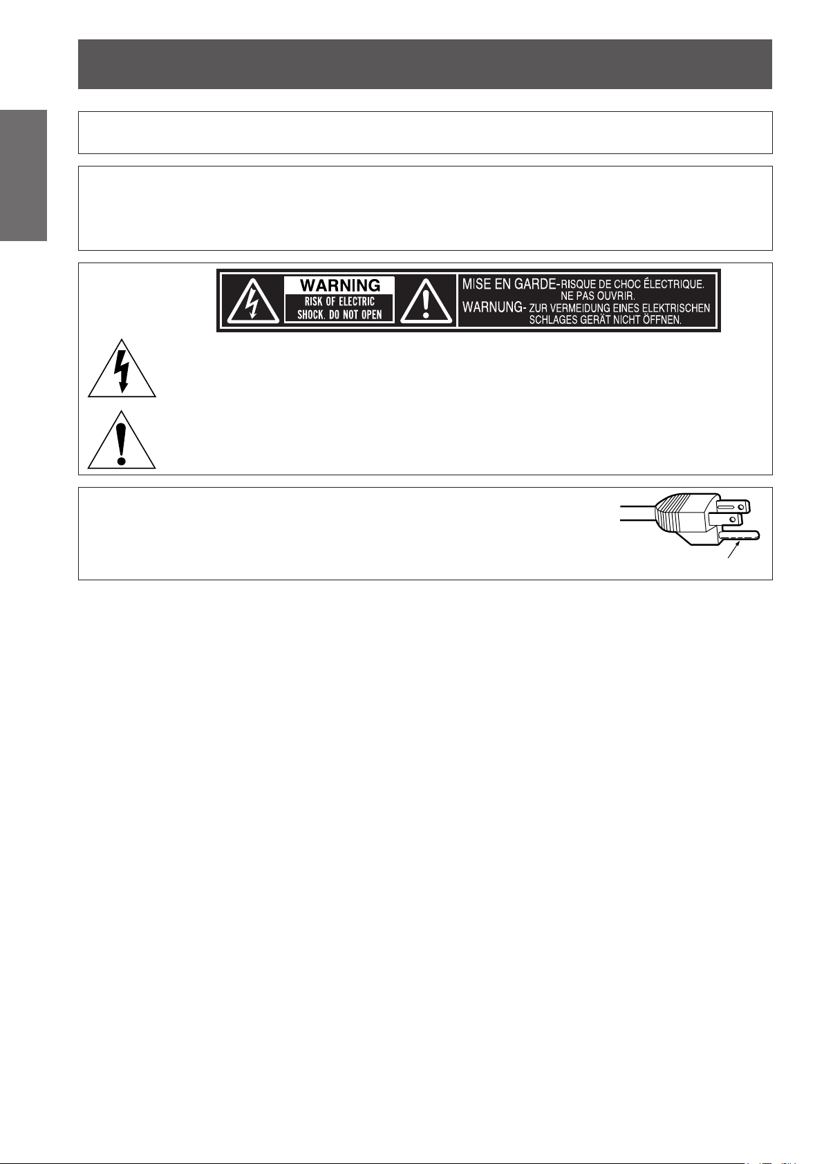
WARNING: TO REDUCE THE RISK OF FIRE OR ELECTRIC SHOCK, DONOT EXPOSE THIS PRODUCT
Power Supply: This Projector is designed to operate on 100 V - 240 V, 50 Hz/60 Hz AC, house current only.
CAUTION: The AC power cord which is supplied with the projector as an accessory can only be used for
CAUTION: This equipment is equipped with a three-pin grounding-type power
TO RAIN OR MOISTURE.
power supplies up to 125 V. If you need to use higher voltages than this, you will need to obtain a
separate 250 V power cord. If you use the accessory cord in such situations, re may result.
The lightning ash with arrowhead symbol, within an equilateral triangle, is intended to alert the
user to the presence of uninsulated “dangerous voltage” within the product’s enclosure that may
be of sufcient magnitude to constitute a risk of electric shock to persons.
The exclamation point within an equilateral triangle is intended to alert the user to the presence of
important operating and maintenance (servicing) instructions in the literature accompanying the
product.
plug. Do not remove the grounding pin on the power plug. This plug
will only t a grounding-type power outlet. This is a safety feature. If
you are unable to insert the plug into the outlet, contact an electrician.
Do not defeat the purpose of the grounding plug.
Do not remove
2 - ENGLISH
Page 3

Read this rst!
FCC NOTICE (USA)
Declaration of Conformity
Model Number: PT-LZ370U
Trade Name: Panasonic
Responsible Party: Panasonic Corporation of North America
Address: One Panasonic Way, Secaucus, NJ 07094
Telephone number: (877)803-8492
E-mail: projectorsupport@us.panasonic.com
This device complies with Part 15 of the FCC Rules.
Operation is subject to the following two conditions:
(1) This device may not cause harmful interference, and (2) this device must accept any interference received,
including interference that may cause undesired operation.
To assure continued compliance, follow the attached installation instructions and do not make any unauthorized
modications.
Caution:
This equipment has been tested and found to comply with the limits for a Class B digital device, pursuant
to Part 15 of the FCC Rules. These limits are designed to provide reasonable protection against harmful
interference in a residential installation. This equipment generates, uses and can radiate radio frequency
energy and, if not installed and used in accordance with the instructions, may cause harmful interference
to radio communications. However, there is no guarantee that interference will not occur in a particular
installation. If this equipment does cause harmful interference to radio or television reception, which can be
determined by turning the equipment off and on, the user is encouraged to try to correct the interference by
one or more of the following measures:
zReorient or relocate the receiving antenna.
zIncrease the separation between the equipment and receiver.
zConnect the equipment into an outlet on a circuit different from that to which the receiver is connected.
zConsult the dealer or an experienced radio/TV technician for help.
FCC Caution:
To assure continued compliance, follow the attached installation instructions and use only shielded interface
cables when connecting to computer and/or peripheral devices. Any changes or modications not expressly
approved by Panasonic Corp. of North America could void the user’s authority to operate this device.
Important
Information
ENGLISH - 3
Page 4

Read this rst!
Information
Important
NOTIFICATION (Canada)
This class B digital apparatus complies with Canadian ICES-003.
WARNING:
NOTICE USA only:
For USA-California Only
This product contains a CR Coin Cell Lithium Battery which contains Perchlorate Material – special handling
may apply.
See www.dtsc.ca.gov/hazardouswaste/perchlorate
zNot for use in a computer room as dened in the Standard for the Protection of Electronic Computer/Data
Processing Equipment, ANSI/NFPA 75.
zFor permanently connected equipment, a readily accessible disconnect device shall be incorporated in the
building installation wiring.
zFor pluggable equipment, the socket-outlet shall be installed near the equipment and shall be easily
accessible.
zThis product has a High Intensity Discharge (HID) lamp that contains mercury. Disposal may be regulated
in your community due to environmental considerations. For disposal or recycling information, please visit
Panasonic website: http://www.panasonic.com/environmental or call 1-888-769-0149.
4 - ENGLISH
Page 5

Read this rst!
WARNING:
POWER
The wall outlet or the circuit breaker shall be installed near the equipment and shall be easily
accessible when problems occur. If the following problems occur, cut off the power supply
immediately.
Continued use of the projector in these conditions will result in re or electric shock.
zIf foreign objects or water get inside the projector, cut off the power supply.
zIf the projector is dropped or the cabinet is broken, cut off the power supply.
zIf you notice smoke, strange smells or noise coming from the projector, cut off the power supply.
Please contact an Authorized Service Center for repairs, and do not attempt to repair the projector yourself.
During a thunderstorm, do not touch the projector or the cable.
Electric shocks can result.
Do not do anything that might damage the power cord or the power plug.
If the power cord is used while damaged, electric shocks, short-circuits or re will result.
zDo not damage the power cord, make any modications to it, place it near any hot objects, bend it
excessively, twist it, pull it, place heavy objects on top of it or wrap it into a bundle.
Ask an Authorized Service Center to carry out any repairs to the power cord that might be necessary.
Completely insert the power plug into the wall outlet and the power connector into the projector terminal.
If the plug is not inserted correctly, electric shocks or overheating will result.
zDo not use plugs which are damaged or wall outlets which are coming loose from the wall.
Do not use anything other than the provided power cord.
Failure to observe this will result in electric shocks or re.
Clean the power plug regularly to prevent it from becoming covered in dust.
Failure to observe this will cause a re.
zIf dust builds up on the power plug, the resulting humidity can damage the insulation.
zIf not using the projector for an extended period of time, pull the power plug out from the wall outlet.
Pull the power plug out from the wall outlet and wipe it with a dry cloth regularly.
Do not handle the power plug and power connector with wet hands.
Failure to observe this will result in electric shocks.
Do not overload the wall outlet.
If the power supply is overloaded (ex., by using too many adapters), overheating may occur and re will result.
Important
Information
ON USE/INSTALLATION
Do not place the projector on soft materials such as carpets or sponge mats.
Doing so will cause the projector to overheat, which can cause burns, re or damage to the projector.
Do not set up the projector in humid or dusty places or in places where the projector may come into
contact with oily smoke or steam, ex. a bathroom.
Using the projector under such conditions will result in re, electric shocks or deterioration of components.
Deterioration of components (such as ceiling mount brackets) may cause the projector which is mounted on
the ceiling to fall down.
Do not install this projector in a place which is not strong enough to take the full weight of the
projector or on top of a surface which is sloped or unstable.
Failure to observe this will cause projector to fall down or tip over the projector, and severe injury or damage
could result.
ENGLISH - 5
Page 6

Read this rst!
Information
Important
WARNING:
Do not cover the air intake/exhaust ports or place anything within 100 mm (4") of them.
Doing so will cause the projector to overheat, which can cause re or damage to the projector.
Do not place your hands or other objects close to the air exhaust port.
Doing so will cause burns or damage your hands or other objects.
Do not look and place your skin into the lights emitted from the lens while the projector is being used.
Doing so can cause burns or loss of sight.
Never attempt to remodel or disassemble the projector.
High voltages can cause re or electric shocks.
Do not project an image with the lens cover attached.
Doing so can cause re.
Do not allow metal objects, ammable objects, or liquids to enter inside of the projector. Do not allow
the projector to get wet.
Doing so may cause short circuits or overheating, and result in re, electric shock, or malfunction of the
projector.
Use the ceiling mount bracket specied by Panasonic.
Defects in the ceiling mount bracket will result in falling accidents.
Installation work (such as ceiling mount bracket) should only be carried out by a qualied technician.
If installation is not carried out and secured correctly it can cause injury or accidents, such as electric shocks.
zDo not place the projector in narrow, badly ventilated places.
zDo not place the projector on cloth or papers, as these materials could be drawn into the air intake port.
zHeated air comes out of the air exhaust port. Do not place your hands or face, or objects which cannot
withstand heat close to this port.
zStrong light is emitted from the projector’s lens. Do not look or place your hands directly into this light.
zBe especially careful not to let young children look into the lens. In addition, turn off the power and
disconnect the power plug when you are away from the projector.
zFor any inspection, adjustment and repair work, please contact an Authorized Service Center.
zDo not place containers of liquid or metal objects near the projector.
zIf liquid enters inside of the projector, consult your dealer.
zParticular attention must be paid to children.
zAttach the supplied safety cable to the ceiling mount bracket to prevent the projector from falling down.
zDo not use anything other than an authorized ceiling mount bracket.
zBe sure to use the provided accessory wire with an eye bolt as an extra safety measure to prevent the
projector from falling down. (Install in a different location to the ceiling mount bracket)
6 - ENGLISH
Page 7

Read this rst!
WARNING:
ACCESSORIES
Do not use or handle the batteries improperly, and refer to the following.
Failure to observe this will cause burns, batteries to leak, overheat, explode or catch re.
zDo not use unspecied batteries.
zDo not disassemble dry cell batteries.
zDo not heat the batteries or place them into water or re.
zDo not allow the + and - terminals of the batteries to come into contact with metallic objects such as
necklaces or hairpins.
zDo not store batteries together with metallic objects.
zStore the batteries in a plastic bag and keep them away from metallic objects.
zMake sure the polarities (+ and -) are correct when inserting the batteries.
zDo not use a new battery together with an old battery or mix different types of batteries.
zDo not use batteries with the outer cover peeling away or removed.
If the battery uid leaks, do not touch it with bare hands, and take the following measures if necessary.
zBattery uid on your skin or clothing could result in skin inammation or injury.
Rinse with clean water and seek medical advice immediately.
zBattery uid coming in contact with your eyes could result in loss of sight.
In this case, do not rub your eyes. Rinse with clean water and seek medical advice immediately.
Do not disassemble the lamp unit.
If the lamp breaks, it could cause injury.
Lamp replacement
The lamp has high internal pressure. If improperly handled, an explosion and severe injury or accidents will
result.
zThe lamp can easily explode if struck against hard objects or dropped.
zBefore replacing the lamp, be sure to disconnect the power plug from the wall outlet.
Electric shocks or explosions can result if this is not done.
zWhen replacing the lamp, turn the power off and allow the lamp to cool for at least one hour before
handling it otherwise it can cause burns.
Do not allow infants or pets to touch the remote control unit.
zKeep the remote control unit out of the reach of infants and pets after using it.
Do not use the supplied power cord with devices other than this projector.
zUsing the supplied power cord with devices other than this projector may cause short circuits or
overheating, and result in electric shock or re.
Remove the depleted batteries from the remote control promptly.
zLeaving them in the unit may result in uid leakage, overheating, or explosion of the batteries.
Important
Information
CAUTION:
POWER
When disconnecting the power cord, be sure to hold the power plug and power connector.
If the power cord itself is pulled, the lead will become damaged, and re, short-circuits or serious electric
shocks will result.
When not using the projector for an extended period of time, disconnect the power plug from the wall
outlet and remove the batteries from the remote control.
Failure to do so may result in re or electric shock.
Disconnect the power plug from the wall outlet before carrying out cleaning the unit.
Failure to do so may result in electric shock.
ENGLISH - 7
Page 8

Read this rst!
Information
Important
CAUTION:
Do not place heavy objects on top of the projector.
Failure to observe this will cause the projector to become unbalanced and fall, which could result in damage or
injury. The projector will be damaged or deformed.
Do not put your weight on this projector.
You could fall or the projector could break, and injury will result.
Do not place the projector in extremely hot locations.
Doing so will cause the outer casing or internal components to deteriorate, or result in re.
Always disconnect all cables before moving the projector.
Moving the projector with cables still attached can damage the cables, which will cause re or electric shocks
to occur.
Do not use the old lamp unit.
If used it could cause lamp explosion.
If the lamp has broken, ventilate the room immediately. Do not touch or bring your face close to the
broken pieces.
Failure to observe this will cause the user to absorb the gas which was released when the lamp broke and
which contains nearly the same amount of mercury as uorescent lamps, and the broken pieces will cause
injury.
ON USE/INSTALLATION
zBe especially careful not to let young children stand or sit on the projector.
zTake particular care in locations exposed to direct sunlight or near stoves.
ACCESSORIES
zIf you believe that you have absorbed the gas or that the gas has got into your eyes or mouth, seek
medical advice immediately.
zAsk your dealer about replacing the lamp unit and check the inside of the projector.
8 - ENGLISH
Page 9
Brazil Only
Brasil Apenas
Read this rst!
Manuseio de baterias usadas
BRASIL
Após o uso, as pilhas e /ou baterias poderão
ser entregues ao estabelecimento comercial
ou rede de assistência técnica autorizada.
Cobrir os terminais positivo (+) e negativo (-) com uma ta isolante adesiva, antes de depositar numa caixa
destinada para o recolhimento. O contato entre partes metálicas pode causar vazamentos, gerar calor, romper
a blindagem e produzir fogo.
Não desmonte, não remova o invólucro, nem amasse a bateria. O gás liberado pela bateria pode irritar a
garganta, danicar o lacre do invólucro ou o vazamento provocar calor, ruptura da blindagem e produzir fogo
devido ao curto circuito dos terminais.
Não incinere nem aqueça as baterias, elas não podem car expostas a temperaturas superiores a 100 °C (212
°F). O gás liberado pela bateria pode irritar a garganta,
danicar o lacre do invólucro ou o vazamento provocar calor, ruptura da blindagem e produzir fogo devido ao
curto circuito dos terminais provocado internamente.
Evite o contato com o liquido que vazar das baterias. Caso isto ocorra, lave bem a parte afetada com bastante
água. Caso haja irritação, consulte um médico.
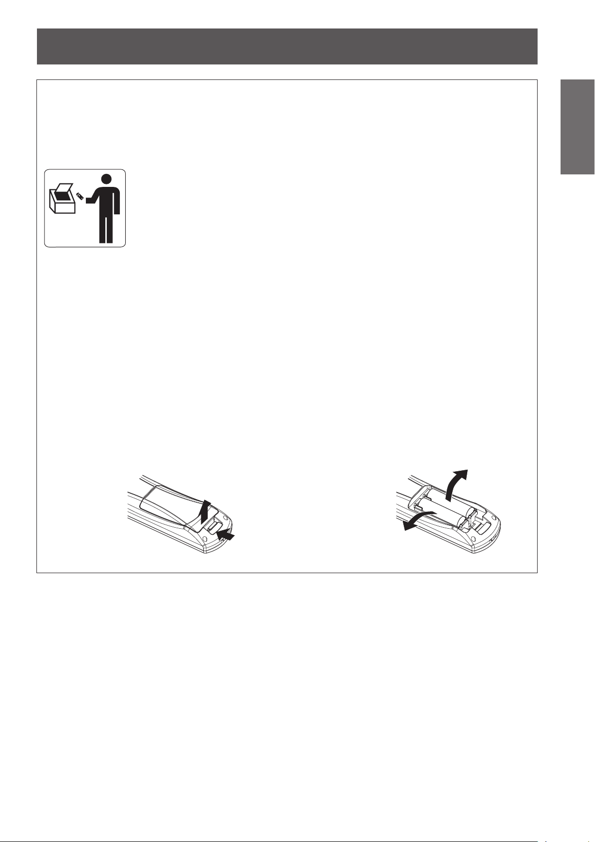
Remoção das baterias
Important
Information
1. Pressione a guia e levante a tampa.
(ii)
(i)
2. Remova as baterias.
ENGLISH - 9
Page 10

Read this rst!
Information
Important
Trademarks
• Microsoft
registered trademarks or trademarks of Microsoft Corporation in the United States and/or other countries.
• Macintosh, Mac OS and Safari are the trademarks of Apple Inc. registered in the United States and other
countries.
• PJLinkTM is a trademark or pending trademark in Japan, the United States, and other countries and regions.
• HDMI, the HDMI logo and High-Denition Multimedia Interface are trademarks or registered trademarks of
HDMI Licensing LLC.
• VGA and XGA are trademarks of International Business Machines Corporation.
• SVGA is a registered trademark of the Video Electronics Standards Association.
• RoomView, Crestron RoomView, and Crestron Connected are trademarks of Crestron Electronics, Inc.
• The font used in the on-screen displays is a Ricoh bitmap font, which is manufactured and sold by Ricoh
Company, Ltd.
• Adobe Flash Player is either a trademark or registered trademark of Adobe Systems Incorporated in the United
States and/or other countries.
• Other names, company names or product names used in these operating instructions are the trademarks or
registered trademarks of their respective holders.
Please note that the operating instructions do not include the ® and TM symbols.
Illustrations in these operating instructions
• Note that illustrations of the projector and screens may differ from the ones you actually see.
Page references
• In these instructions, references to pages are indicated as: ( page 00).
Term
• In these instructions, the “Wireless remote control unit” accessory is referred to as the “Remote control”.
®
and its logos, Windows®, Windows® XP, Windows Vista®, Windows® 7, and Internet Explorer® are the
10 - ENGLISH
Page 11
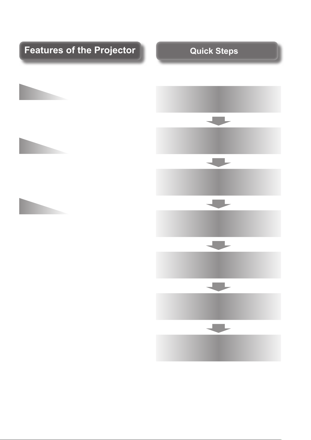
Quick StepsQuick Steps
Features of the ProjectorFeatures of the Projector
Easy setup and improved
For details, see the corresponding pages.
serviceability
The 2x zoom lens and the lens shift
allow more exible setup of the
projector.
Improved color
reproducibility and contrast
A new lamp and optical system have
been introduced to improve color
reproducibility and contrast.
Harmonization with
projection environment
This projector is equipped with
technology to automatically adjust
the image according to the lighting
of the projection environment
(brightness, color).
1. Set up your projector.
( page 25)
2. Connect with other devices.
( page 32)
3. Connect the power cord.
page 35)
(
4. Switch on the projector.
( page 37)
5. Make initial settings.
*1
( page 20)
6. Select the input signal.
( page 39)
7. Adjust the image.
( page 39)
*1: This is the step to be taken when you switch on the power
for the rst time after purchase.
ENGLISH - 11
Page 12

Contents
Contents
Be sure to read “Read this rst!”. (
pages
2 to 10)
Information
Important
Important Information
Read this rst! ............................................ 2
Precautions for use ...................................14
Preparation Getting Started Basic Operation Settings Maintenance Appendix
Preparation
Start-up display ........................................ 20
About your projector ................................21
Using Remote control .............................. 24
Getting Started
Setting up .................................................. 25
Connections ............................................. 32
Basic Operation
Switching on/off ....................................... 35
Projecting.................................................. 39
Remote control operation .........................41
Cautions when transporting .............................14
Cautions when installing ..................................14
Security ...........................................................16
Disposal .......................................................... 16
Cautions on use .............................................. 17
Accessories ....................................................18
Optional accessories ....................................... 19
Remote control ................................................21
Projector body .................................................22
Inserting and removing the batteries ................ 24
Setting Remote control ID numbers .................24
Projection method ........................................... 25
Parts for ceiling mount (optional) .....................25
Screen size and throw distance .......................26
Adjusting adjustable feet ................................. 28
Lens shift and positioning ................................ 28
Before connecting to the projector ...................32
Connecting example: Input terminals ............... 33
Connecting the power cord .............................. 35
Power indicator ............................................... 36
Switching on the projector ...............................37
Switching off the projector ...............................38
Direct power off function ..................................38
Selecting the input signal .................................39
Adjusting the image ......................................... 39
Using the AV mute function..............................41
Using the Freeze function ................................ 41
Switching the input ..........................................42
Using the Automatic setup function ..................42
Using the Function button ................................43
Using the ECO management function ..............43
Resetting to the factory default ........................43
Adjusting the volume .......................................43
Settings
Menu navigation ....................................... 44
Navigating through the menu ...........................44
Main menu ...................................................... 46
Sub menu........................................................46
[PICTURE] menu ....................................... 48
[PICTURE MODE] ...........................................48
[CONTRAST] .................................................. 48
[BRIGHTNESS] ............................................... 49
[COLOR] ......................................................... 49
[TINT] ..............................................................49
[SHARPNESS] ................................................49
[COLOR TEMPERATURE] ..............................49
[DYNAMIC IRIS] ..............................................50
[WAVEFORM MONITOR] ................................50
[ADVANCED MENU] .......................................53
[DAYLIGHT VIEW] ..........................................54
[DIGITAL CINEMA REALITY]...........................54
[NOISE REDUCTION] .....................................54
[TV-SYSTEM]..................................................55
[RGB/YC
[POSITION] menu ..................................... 56
[KEYSTONE] ..................................................56
[SHIFT] ...........................................................56
[DOT CLOCK] .................................................57
[CLOCK PHASE] .............................................57
[OVER SCAN] .................................................58
[ASPECT] .......................................................58
[FRAME LOCK] ...............................................60
[LANGUAGE] menu ...................................61
Changing the display language ........................ 61
[DISPLAY OPTION] menu ......................... 62
[ON-SCREEN DISPLAY] .................................62
[HDMI SIGNAL LEVEL] ................................... 63
[CLOSED CAPTION SETTING] .......................63
[STARTUP LOGO] ..........................................64
[AUTO SETUP SETTING] ...............................64
[SIGNAL SEARCH] .........................................64
[BACK COLOR] ..............................................65
[SXGA MODE] ................................................ 65
[OTHER FUNCTIONS] .................................... 65
[PROJECTOR SETUP] menu .................... 66
[STATUS] ........................................................66
[PROJECTOR ID] ............................................66
[INITIAL START UP] ........................................67
[PROJECTION METHOD] ...............................67
]/[RGB/YPBPR] .............................55
BCR
12 - ENGLISH
Page 13

Contents
[HIGH ALTITUDE MODE] ................................67
[LAMP POWER] ..............................................68
[LAMP RUNTIME] ...........................................68
[SCHEDULE] ...................................................68
[ECO MANAGEMENT] ....................................69
[EMULATE] .....................................................71
[FUNCTION BUTTON] ....................................71
[AUDIO SETTING] ..........................................72
[DATE AND TIME] ...........................................73
[TEST PATTERN] ............................................74
[INITIALIZE ALL] .............................................74
[SECURITY] menu .................................... 75
[PASSWORD] .................................................75
[PASSWORD CHANGE] .................................75
[DISPLAY SETTING] .......................................76
[TEXT CHANGE] .............................................76
[MENU LOCK] .................................................76
[MENU LOCK PASSWORD] ...........................77
[CONTROL DEVICE SETUP] ..........................77
[NETWORK] menu .................................... 78
[WIRED LAN] ..................................................78
[NAME CHANGE] ...........................................78
[NETWORK CONTROL] ................................. 79
[STATUS] ........................................................79
[INITIALIZE].....................................................79
Network connections ....................................... 80
Required environment for computer
connection ................................................ 80
Network settings of computer .......................... 81
Accessing from the Web browser .................... 81
Ceiling mount bracket safeguards .........120
Index ........................................................121
Important
Information
PreparationGetting StartedBasic OperationSettingsMaintenanceAppendix
Maintenance
<LAMP> and <TEMP> indicators ............. 97
Managing the indicated problems ....................97
Maintenance/replacement ........................ 99
Before maintaining/replacing the unit ............... 99
Maintenance ...................................................99
Replacing the unit .......................................... 101
Troubleshooting ......................................107
Appendix
Technical information ..............................109
PJLink protocol ..............................................109
Control commands via LAN ........................... 110
<SERIAL> terminal ........................................ 113
Menu lock password...................................... 115
List of compatible signals ............................... 116
Specications ..........................................118
Dimensions ..............................................120
ENGLISH - 13
Page 14

Precautions for use
Precautions for use
Information
Important
Cautions when transporting
Cautions when installing
Be sure to use the projector after removing the packaging material, such as
the fastening tapes and protective sheet.
Take proper care when disposing of the removed packaging material.
zWhen transporting the projector, be sure to attach the supplied lens cover to the projection lens.
zWhen transporting the projector, hold it securely by its bottom and avoid excessive vibration and impacts.
Doing so may damage the internal parts and result in malfunctions.
zDo not transport the projector with the adjustable feet extended. Doing so may damage the adjustable feet.
Do not set up the projector outdoors.
The projector is designed for indoor use only.
Do not use under the following conditions.
Places where vibration and impacts occur such as in a car or vehicle: Doing so may damage the internal
z
parts and result in malfunctions.
Near the exhaust of an air conditioner: Depending on the conditions of use, the screen may uctuate due
z
to the hot air from the air exhaust port or the heated or cooled air from the air conditioner. Take care so that
the exhaust from the projector or other equipment, or the air from the air conditioner does not blow toward
the front of the projector.
Near lights (studio lamps, etc.) where temperature changes greatly (“Operating environment” (
z
Doing so may shorten the life of the lamp or result in deformation of the outer case and malfunctions.
Near high-voltage power lines or near motors: Doing so may interfere with the operation of the projector.
z
page 119)):
Be sure to ask a specialized technician when installing the product to a ceiling.
If the product is to be installed hanging from the ceiling, purchase an optional Ceiling Mount Attachment.
Model No.: ET-PKA110H (for high ceilings), ET-PKA110S (for low ceilings)
Lens focus
The high clarity projection lens is thermally affected by the light from the light source, making the focus
unstable in the period just after switching on the power. Wait at least 30 minutes with the image projected
before adjusting the lens focus.
Make sure to set [HIGH ALTITUDE MODE] to [ON] when using the projector
at elevations of 1 400 m (4 593 ft) or higher and lower than 2 700 m (8 858 ft)
above sea level.
Failure to do so may shorten the life of the internal parts and result in malfunctions.
Make sure to set [HIGH ALTITUDE MODE] to [OFF] when using the projector
at elevations lower than 1 400 m (4 593 ft) above sea level.
Failure to do so may shorten the life of the internal parts and result in malfunctions.
Do not install the projector at elevations of 2 700 m (8 858 ft) or higher above
sea level.
Failure to do so may shorten the life of the internal parts and result in malfunctions.
14 - ENGLISH
Page 15
Precautions for use
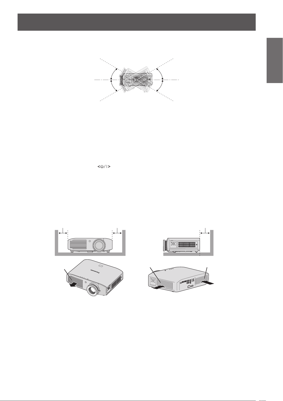
100 mm (4") or more 100 mm (4") or more 100 mm (4") or more
Do not tilt the projector or place it on its side.
Do not tilt the projector body more than approximately ±30° vertically or ±10° horizontally. Overtilting may
result in shortening the life of the components.
30°
30°
Do not cover the air intake/exhaust ports or place anything within 100 mm (4")
of them.
Avoid using the projector at places where there are higher static electricity
levels as far as possible.
When using the projector in places such as on a carpet where there are static electricity, communication
z
using wired LAN may be distorted.
In such cases, remove the source of static electricity or noise and connect wired LAN again.
In rare cases, communication via LAN may not be possible due to static electricity or noise.
z
In such cases, press the power
the projector.
After the cooling fan is stopped (after the power indicator <ON (G)/STANDBY (R)> of the projector body
that is illuminating orange changes the indication to illuminate or ash red), turn on the power and connect
to the LAN again.
button on the remote control or control panel to turn off the power of
Cautions when setting the projectors
Do not stack the projectors.
z
Avoid heating and cooling air from the air conditioning system directly blow to the ventilation ports (intake
z
and exhaust) of the projector.
Do not block the ventilation ports (intake and exhaust) of the projector.
z
Important
Information
Air exhaust port
Air intake port
Air intake port
ENGLISH - 15
Page 16
Precautions for use
Information
Important
Security
Take safety measures against following incidents.
Take sufcient security measures. (
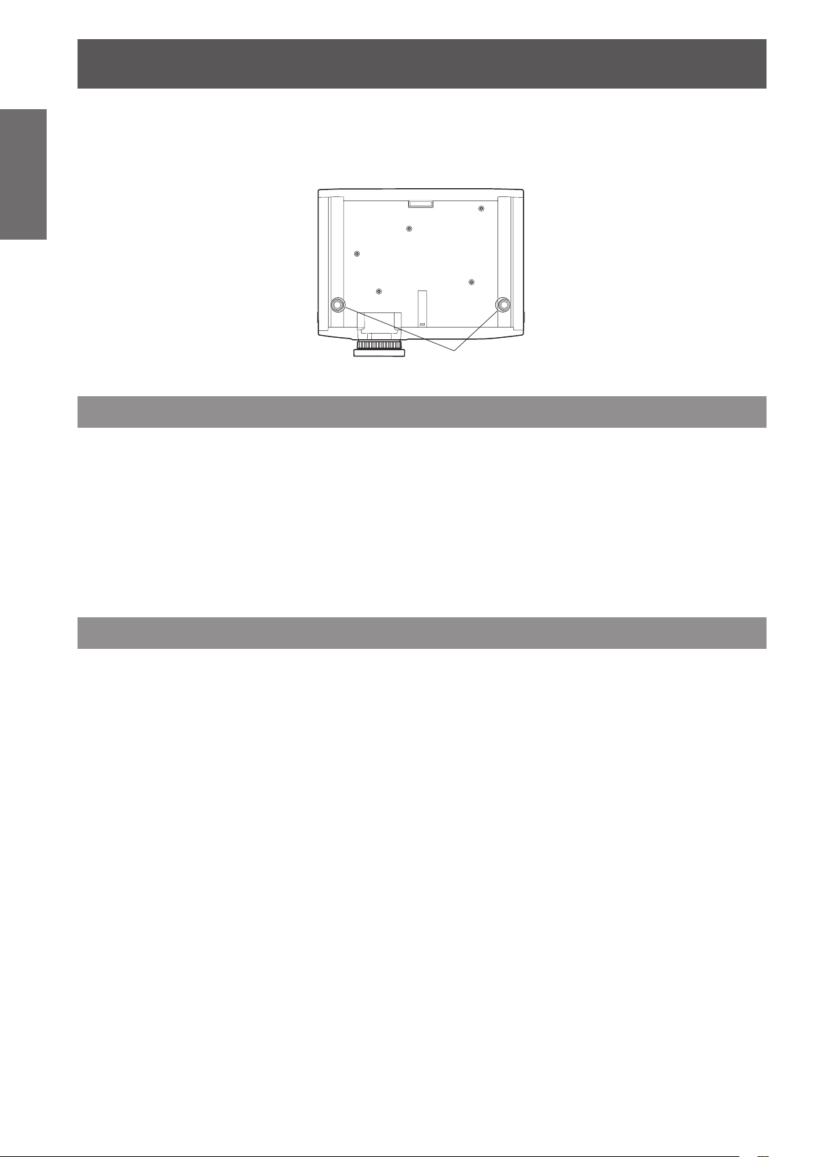
Do not install the projector in a conned space.
z
When it is necessary to install in a conned space, use air conditioning or ventilation separately. Exhaust
heat may accumulate when the ventilation is not enough, triggering the protection circuit of the projector.
Use the adjustable feet only for the oor standing installation and for adjusting the angle. If you use it other
z
than this purpose, the projector may be damaged.
Adjustable feet
Personal information being leaked via this product
z
Unauthorized operation of this product by a malicious third party
z
Interfering or stopping of this product by a malicious third party
z
page 75)
Make your password as difcult to guess as possible.
z
Change your password periodically.
z
Panasonic Corporation or its afliate company never inquires a password directly to a customer. Do not tell
z
your password in case you receive such an inquiry.
The connecting network must be secured by rewall or others.
z
Set a password and restrict the users who can log in.
z
Disposal
To dispose of the product, inquire your local authorities or dealer for correct methods of disposal.
The lamp contains mercury. When disposing of used lamp units, contact your local authorities or dealer for correct
methods of disposal.
16 - ENGLISH
Page 17

Precautions for use
Cautions on use
In order to get the picture quality
Draw curtains or blinds over windows and turn off any lights near the screen to prevent outside light or light
z
from indoor lamps from shining onto the screen, in order to obtain high-quality images with higher contrast.
Depending on the conditions of use, the screen may uctuate due to the hot air from the air exhaust port or
z
the heated or cooled air from the air conditioner.
Take care so that the exhaust from the projector or other equipment, or the air from the air conditioner does
not blow toward the front of the projector.
The projection lens is thermally affected by the light from the light source, making the focus unstable in the
z
period just after switching on. Focus stabilizes 30 minutes after video projection starts.
Do not touch the surface of the projection lens with your bare hands.
If the surface of the lens becomes dirty from ngerprints or anything else, this will be magnied and projected
onto the screen. Please put the lens cover (accessory) on the projector when you do not use it.
LCD panel
The LCD panel is precision-made. Note that in rare cases, pixels of high precision could be missing or always
lit. This is not a malfunction.
Also, projecting a still image for extended periods of time may lead to afterimages on LCD panels. Please be
aware that in some cases these afterimages may not disappear completely.
Optical components
If using in an environment with a high temperature, or where dust or tobacco smoke is present, the
replacement cycle of optical components such as LCD panels and polarizing plates may shorten even after
less than one year of use. For more details, please consult your dealer.
Lamp
The luminous source of the projector is a mercury lamp with high internal pressure.
A high pressure mercury lamp has following characteristics.
The brightness of the lamp will decrease by duration of usage.
z
The lamp may burst with sound or shorten life by shock or chipping.
z
The life of the lamp varies greatly depending on individual specicities and usage conditions. In particular,
z
continuous use over 12 hours and frequent on/off switching of the power greatly deteriorate the lamp and
affect the lamp life.
In rare cases, the lamp burst shortly after the projection.
z
The risk of bursting increases when the lamp is used beyond its replacement cycle. Make sure to replace
z
the lamp unit consistently.
(When to replace the lamp unit ( page 103), Replacing the lamp unit ( page 104))
If the lamp bursts, gas contained inside of the lamp is released in a form of smoke.
z
It is recommended to store replacement lamps for contingency.
z
Important
Information
<Software information regarding this product>
© Panasonic Corporation 2011
This product incorporates the following software:
(1) the software which is developed independently by or for Panasonic Corporation
(2) the software which is licensed under the GNU GENERAL PUBLIC LICENSE. and
(3) the software which is licensed under the GNU LESSER GENERAL PUBLIC LICENSE.
For the software categorized as (2) and (3), the license is available in accordance with GNU GENERAL PUBLIC LICENSE and
GNU LESSER GENERAL PUBLIC LICENSE respectively. As for the terms and conditions, please refer to the software license of
the supplied CD-ROM.
If you wish to ask any questions as to the software, please contact (sav.pj.gpl.pavc@ml.jp.panasonic.com) by email.
ENGLISH - 17
Page 18
Precautions for use
Information
Important
Accessories
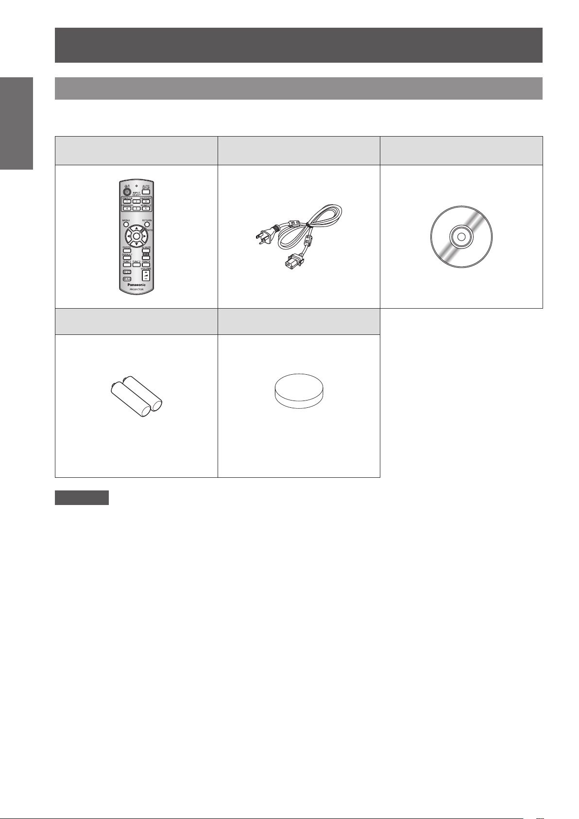
Make sure that the following accessories are provided with your projector. Numbers in the brackets ( ) show the
number of accessories.
Wireless remote control unit (x1)
(N2QAYB000696)
AA/R6 battery (x2) Lens cover (x1)
Power cord (x1)
(TXFSX02RWFZ)
(TEEC5524)
CD-ROM (x1)
(TXFQB02VKQ4)
(For remote control unit)
Attention
zAfter unpacking the projector, discard the power cord cap and packaging material properly.
zFor lost accessories, consult your dealer.
zThe part numbers of accessories and separately sold components are subject to change without notice.
zStore small parts in an appropriate manner, and keep them away from young children.
zStore the lens cover properly.
The lens cover protects the projection lens from dust and dirt.
Please put the supplied lens cover on the projector when you do not use it.
(Attached to the projector at the
time of purchase)
18 - ENGLISH
Page 19

Contents of the supplied CD-ROM
■■
The contents of the supplied CD-ROM are as follows.
Instruction/list (PDF) Software
Precautions for use
Operating Instructions – Functional
z
■
Manual
Multi Projector Monitoring & Control
z
■
Multi Projector Monitoring & Control
z
■
Software (Windows)
This software allows you to monitor and control
–■
multiple projectors connected to the LAN.
Software Operation Manual
Logo Transfer Software (Windows)
z
Logo Transfer Software Operation
z
■
Manual
List of Compatible Projector Models
z
■
This is a list of projectors that are compatible with
–■
the software contained in the CD-ROM and their
restrictions.
Software license
z
■
(GNU GENERAL PUBLIC LICENSE, GNU
LESSER GENERAL PUBLIC LICENSE)
■
This software allows you to create original
–■
images, such as company logos to be displayed
when projection starts, and transfer them to the
projector.
Optional accessories
Optional accessories
(product name)
Ceiling mount bracket ET-PKA110H (for high ceilings), ET-PKA110S (for low ceilings)
Replacement lamp unit ET-LAA110
Model No.
Important
Information
ENGLISH - 19
Page 20
Start-up display
Start-up display
The initial setting screen is displayed when the projector is turned on for the rst time after purchase or when
executing [INITIALIZE ALL] ( page 74). Set them in accordance with circumstances.
In other occasions, you can change the settings by menu operations.
Note
zWhen the projector is turned on for the rst time, you may be required to adjust with the zoom ring and focus
ring in the front of the projector body to make the menu screen clearer.
Refer to “Adjusting the image” (
page 39) for details.
Preparation
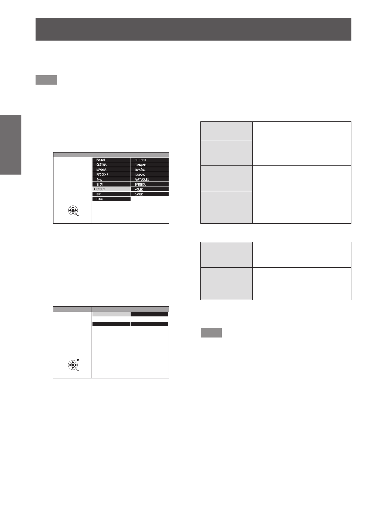
Select the language to show on the screen. ( page 61)
1) Press
2) Press the <ENTER> button to proceed
Select an item for each of [PROJECTION METHOD]
and [HIGH ALTITUDE MODE].
1) Press
2) Press
Initial setting (display language)
to select the desired
language.
INITIAL SETTING
SELECT
ENTER
PLEASE SELECT LANGUAGE.
to the initial setting.
Initial setting (projector setup)
to select an item.
to switch the setting.
INITIAL SETTING
SELECT
PROJECTION METHOD
HIGH ALTITUDE MODE OFF
SWITCH TO HIGH ALTITUDE MODE "ON" IF OVER
1400m(4593Ft).
RETURN
ENTER
FRONT/DESK
[PROJECTION METHOD] (
z
[FRONT/DESK]
[FRONT/
CEILING]
[REAR/DESK]
[REAR/
CEILING]
[HIGH ALTITUDE MODE] (
z
[OFF]
[ON]
Setting on a desk, etc., in front of
the screen
Mounting on a ceiling using the
ceiling mount bracket (optional) in
front of the screen
Setting on a desk, etc., behind
the screen (using a translucent
screen)
Mounting on a ceiling using the
ceiling mount bracket (optional)
behind the screen (using a
translucent screen)
Using the projector at a place
lower than 1 400 m (4 593 ft)
above sea level
Using the projector at a high
altitude (1 400 m (4 593 ft) or
higher and lower than 2 700 m
(8 858 ft) above sea level)
page 67)
page 67)
3) Press the <ENTER> button to complete
the initial setting.
Note
zIf you press the <RETURN> button in the initial
setting (projector setup) screen, you can go back to
the initial setting (display language) screen.
20 - ENGLISH
Page 21
About your projector
Remote control
About your projector
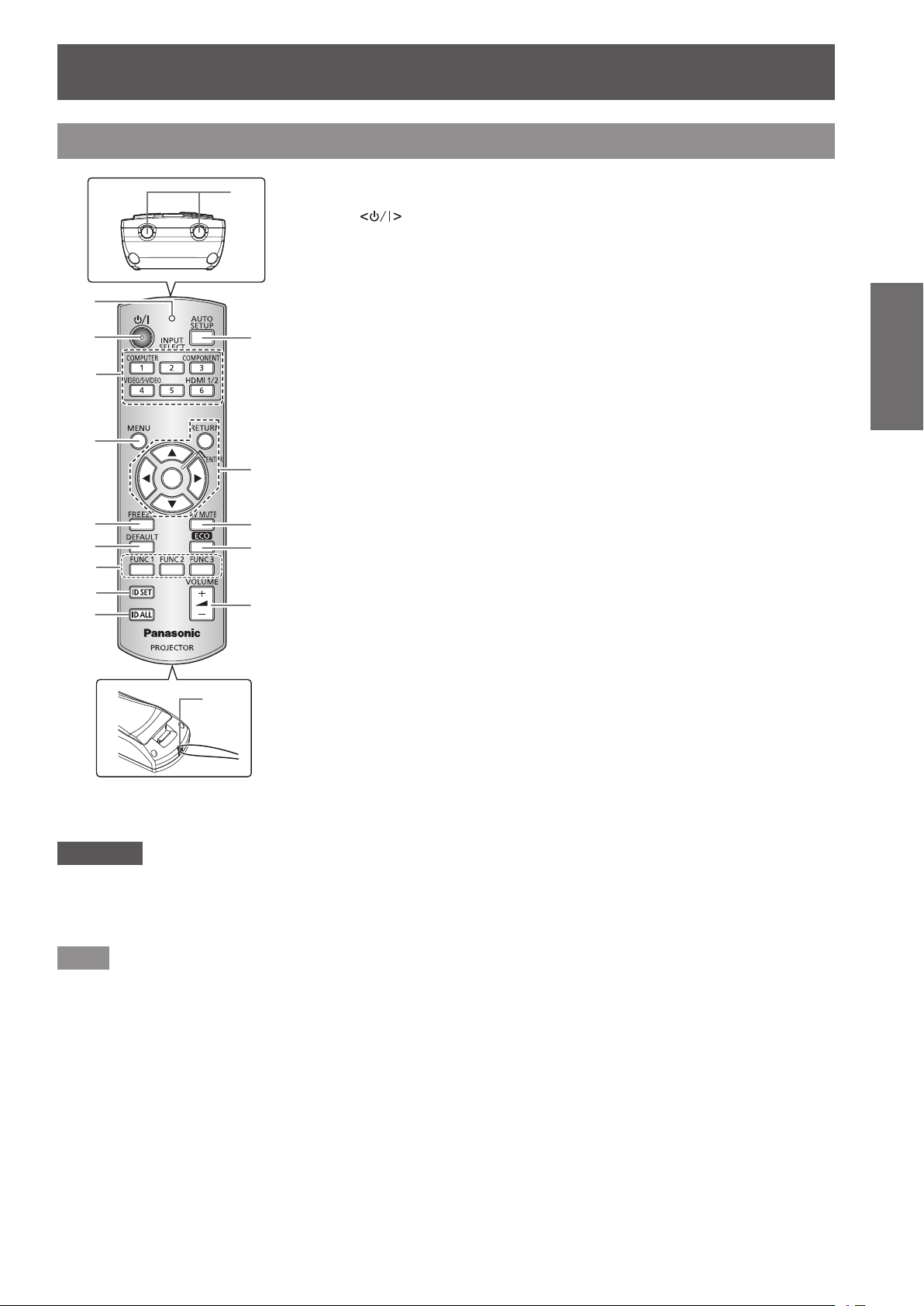
(1)
(2)
(3)
(4)
(5)
(6)
(7)
(8)
(9)
(16)
(15)
(1) Remote control indicator
Flashes by pressing any buttons.
(2) Power
Sets the projector to the standby mode when the <MAIN POWER> switch on the
projector is set to <ON>. Starts projection when the projector power is off and in the
standby mode.
(3) Input selection (<COMPUTER>, <COMPONENT>, <VIDEO/S-VIDEO>, and <HDMI
1/2>) buttons
Switches the input signal to project. (
(10)
(11)
(12)
(13)
(14)
Used to set the ID number of the remote control and a security password. (
(4) <MENU> button
Displays the main menu screen. (
(5) <FREEZE> button
Used to temporarily freeze the image and turn off sound. (
(6) <DEFAULT> button
Restores the contents of the sub-menu to the factory default setting. (
(7) <FUNC1> to <FUNC3> buttons
Assigns a frequently used operation and use as a shortcut button. (
(8) <ID SET> button
Sets the ID number of the remote control when the system uses multiple projectors.
page 24)
(
(9) <ID ALL> button
Simultaneously controls all the projectors with one remote control when the system uses
multiple projectors. (
(10) <AUTO SETUP> button
Automatically adjusts [SHIFT], [DOT CLOCK], and [CLOCK PHASE] when computer
signal is input.
(11)
Used to operate the menu screen.
Also used to enter the password for [SECURITY] or to enter characters.
(12) <AV MUTE> button
Used to temporarily turn off the image and sound. (
(13) <ECO> button
Displays the setting screen for the ECO management. (
(14) <VOLUME +>/<VOLUME
Adjusts the volume of the audio output. (
(15) Remote control signal transmitter
(16) Strap hole
Attach a strap onto the remote control for your convenience.
button
page 42)
page 44)
page 24)
buttons/<RETURN> button/<ENTER> button
page 41)
-
> button
page 43)
page 41)
page 43)
page 43)
page 24)
page 45)
Preparation
Attention
zDo not drop the remote control.
zAvoid contact with liquids or moisture.
zDo not attempt to modify or disassemble the remote control.
zWhen strap is attached to the remote control, do not ing the remote control while holding the strap.
Note
zThe remote control can be used within a distance of about 15 m (49'2") if pointed directly at the remote control
receiver. The remote control can control at angles of up to ±15° vertically and ±30° horizontally, but the effective
control range may be reduced.
zIf there are any obstacles between the remote control and the remote control signal receptor, the remote
control may not operate properly.
zThe signal will be reected off the screen. However, the operating range may differ due to the screen material.
zIf the remote control signal receptor receives strong light such as uorescent light directly, the remote control
may not operate properly. Use it in a place distant from the light source.
ENGLISH - 21
Page 22
About your projector
Projector body
Preparation
(9)
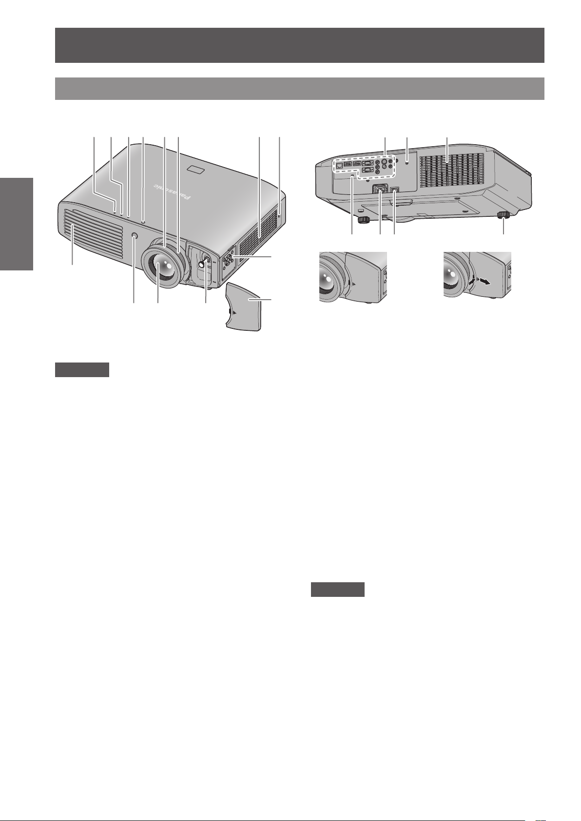
Front, top, and side view Rear and bottom view
(1)
(2) (3) (4) (5) (6) (7) (8) (15) (10) (7)
(17)(16) (18) (19)
(13)
(10) (11) (12)
(14)
Attention
zKeep your hands and other objects away from the
air exhaust port.
Keep your hands and face away.
Do not insert your ngers.
Keep heat-sensitive articles away.
Heated air from the air exhaust port can cause burns,
injury, or deformations.
(1) Power indicator <ON (G)/STANDBY (R)>
Displays the status of the power.
(2) Lamp indicator <LAMP>
Displays the status of the lamp.
(3) Temperature indicator <TEMP>
Displays the status of the internal temperature or the air
lter unit.
(4) Color sensor window
Detects the brightness and color of the surroundings.
(5) Focus ring
Adjusts focus.
(6) Zoom ring
Adjusts zoom.
(7) Air intake port
(8) Air lter cover
There is an air lter unit inside. (
page 99)
Removing the lens shift cover
When the lens shift
cover is attached
(9) Air exhaust port
(10) Remote control signal receiver
(11) Projection lens
(12) Lens shift lever
Adjusts lens shift.
(13) Control panel (
(14) Lens shift cover
(15) Connecting terminals (
(16) Security slot
This security slot is compatible with the Kensington
security cables.
(17) <AC IN> terminal
Connect the supplied power cord.
(18) <MAIN POWER> switch
Turns off/on the main power.
(19) Adjustable feet
Adjusts the projection angle.
Press the lens shift cover and slide
it to remove.
page 23)
page 23)
Attention
zDo not block the ventilation ports (intake and
exhaust) of the projector.
22 - ENGLISH
Page 23
Control panel
About your projector
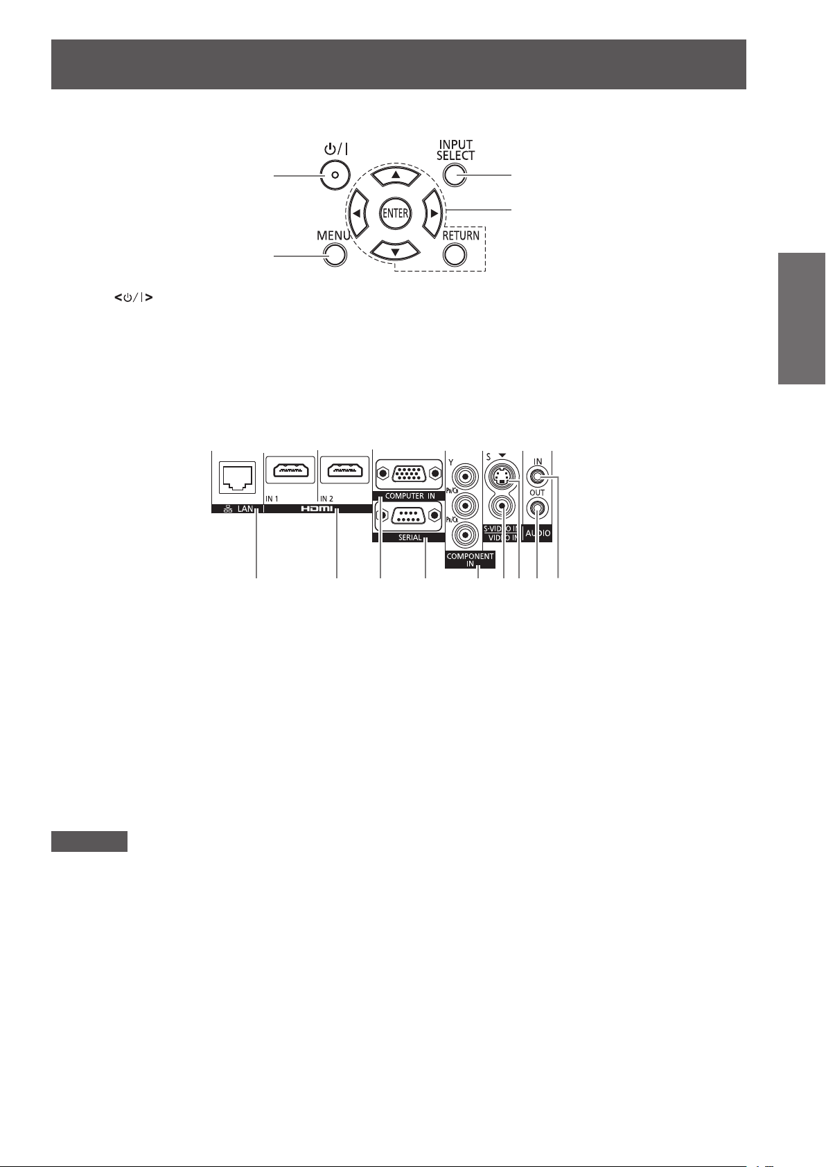
(1)
(2)
(1) Power button
Sets the projector to the standby mode when the <MAIN
POWER> switch on the projector is set to <ON>. Starts
projection when the projector power is off and in the
standby mode.
(2) <MENU> button
Displays the main menu.
Connecting terminals
(3)
(4)
(3) <INPUT SELECT> button
Switches the input signal to project. (
(4)
Used to operate the menu screen.
Also used to enter the password for [SECURITY] or to
enter characters.
buttons/<RETURN> button/<ENTER> button
page 42)
Preparation
(1) (2) (3) (4) (5) (6)(7) (8) (9)
(1) <LAN> terminal
This is a terminal to connect to the network.
(2) <HDMI IN 1>/<HDMI IN 2> terminals
This is a terminal to input the HDMI signal.
(3) <COMPUTER IN> terminal
This is a terminal to input the RGB signal or the YC
signal.
YP
BPR
(4) <SERIAL> terminal
This is a RS-232C compatible terminal to externally control
the projector by connecting a computer.
(5) <COMPONENT IN> terminal
This is a terminal to input the YC
signal.
signal or the YPBPR
BCR
BCR
/
(6) <VIDEO IN> terminal
This is a terminal to input the video signal.
(7) <S-VIDEO IN> terminal
This is a terminal to input the S-video signal.
(8) <AUDIO OUT> terminal
This is a terminal to output the audio signal input to the
projector.
(9) <AUDIO IN> terminal
This is a terminal to input the audio signal.
Attention
zWhen a LAN cable is directly connected to the projector, the network connection must be made indoors.
ENGLISH - 23
Page 24

Using Remote control
Using Remote control
Inserting and removing the batteries
1) Open the cover.
Preparation
Setting Remote control ID numbers
When you use the system with multiple projectors, you can operate all the projectors simultaneously or each
projector individually using single remote control, if a unique ID number is assigned to each projector.
After setting the ID number of the projector, set same ID number on the remote control.
The ID number of the projector is set to [ALL] by the factory default. When using a single projector, press
the <ID ALL> button on the remote control. If you are not sure of the ID number of the projector, you can
control the projector by pressing the <ID ALL> button.
1) Press the <ID SET> button on the remote control.
How to set
(ii)
(i)
2) Insert the batteries and close the cover
(insert the
When removing the batteries, perform the steps
z
in the reverse order.
side rst).
2) Within ve seconds, press the one-digit ID number set on the projector using the
number (<1> - <6>) buttons.
If you press the <ID ALL> button, you can operate the projectors regardless the setting of the projectors’ ID
z
numbers.
Attention
zSince setting of the ID number on the remote control can be performed even without the projector, do not press
the <ID SET> button carelessly. If you press the <ID SET> button and do not press the number (<1> - <6>)
buttons within ve seconds, the ID will remain the same as before the <ID SET> button was pressed.
zThe ID number set on the remote control will be stored unless it is set again. However, it will be erased if the
remote control is left with dead batteries. Set the same ID number again when the batteries are replaced.
Note
zSet the ID number of the projector from the [PROJECTOR SETUP] menu → [PROJECTOR ID] (
page 66).
24 - ENGLISH
Page 25
Setting up
Setting up
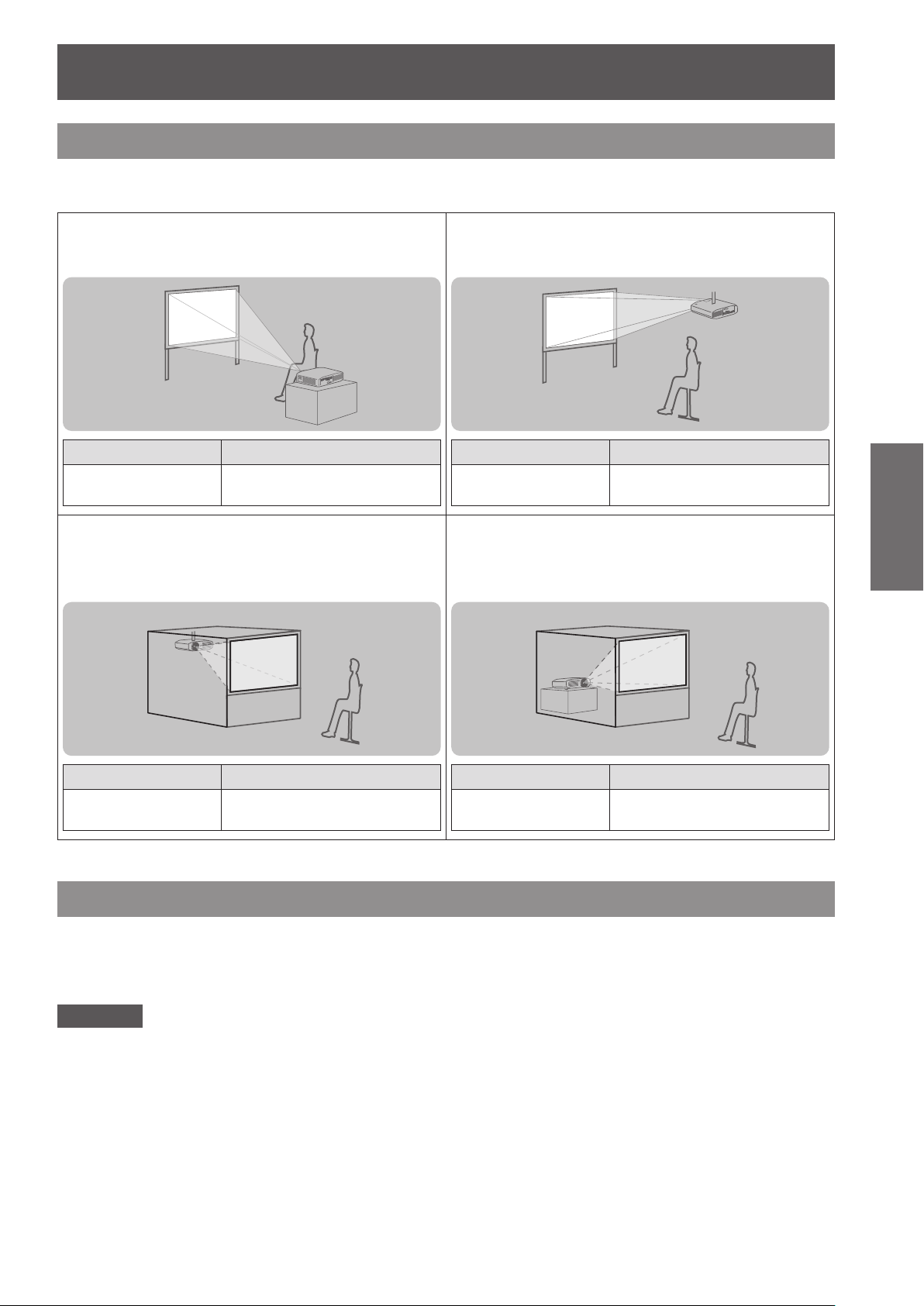
Projection method
You can use the projector with any of the following four projection methods. Select the appropriate method
depending on the environment.
Setting on a desk/oor and
projecting forward
Menu item
[PROJECTION
METHOD]
Mounting on the ceiling and
*1
Method
[FRONT/DESK]
projecting from rear
(Using the translucent screen)
Mounting on the ceiling and
projecting forward
Menu item
[PROJECTION
METHOD]
Setting on a desk/oor and
*1
Method
[FRONT/CEILING]
projecting from rear
(Using the translucent screen)
Getting Started
Menu item
[PROJECTION
METHOD]
*1: For details of the menu items, conrm from the [PROJECTOR SETUP] menu → [PROJECTION METHOD] ( page 67).
*1
Method
[REAR/CEILING]
Menu item
[PROJECTION
METHOD]
*1
Method
[REAR/DESK]
Parts for ceiling mount (optional)
You can install the projector on the ceiling using the optional ceiling mount bracket (ET-PKA110H: for high
ceilings, ET-PKA110S: for low ceilings).
zUse only the ceiling mount brackets specied for this projector.
zRefer to the installation manual for the ceiling mount bracket when you install the bracket and the projector.
Attention
zTo ensure the projector performance and security, installation of the ceiling mount bracket must be carried out
by your dealer or a qualied technician.
ENGLISH - 25
Page 26
Setting up
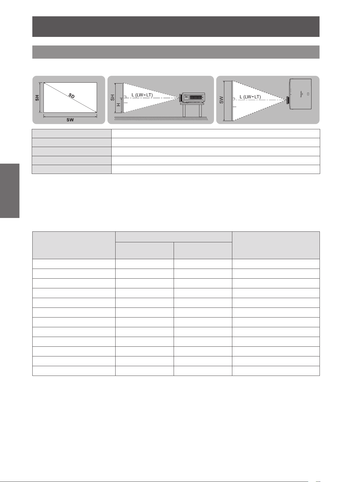
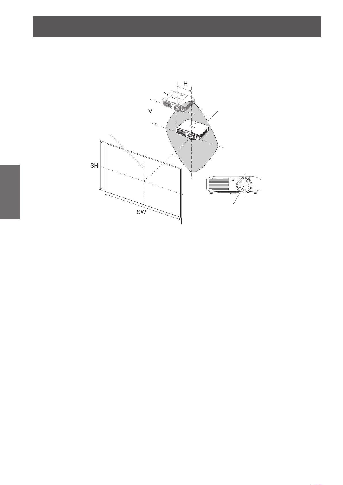
Screen size and throw distance
Install the projector referring to the following gures and tables describing projection distances. Image size and
image position can be adjusted in accordance with the screen size and screen position.
Projection screen
Getting Started
*1: LW: Minimum projection distance
LT: Maximum projection distance
Projection distance
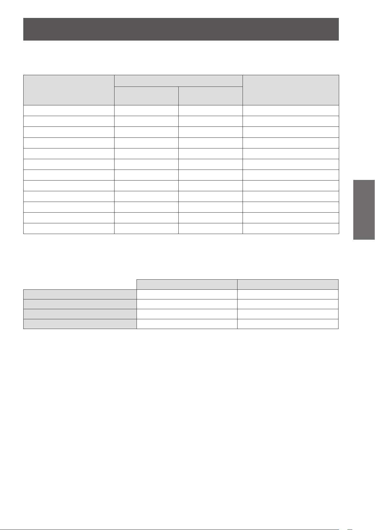
When the screen aspect ratio is 16:9
z
(All measurements below are approximate and may differ slightly from the actual measurements.)
Image diagonal size (SD)
1.02 (40") 1.11 (3' 8") 2.29 (7' 6")
1.27 (50") 1.41 (4' 8") 2.87 (9' 5")
1.52 (60") 1.70 (5' 7") 3.46 (11' 4")
1.78 (70") 1.99 (6' 6") 4.04 (13' 3")
2.03 (80") 2.28 (7' 6") 4.62 (15' 2")
2.29 (90") 2.57 (8' 5") 5.21 (17' 1")
2.54 (100") 2.87 (9' 5") 5.79 (19' 0")
3.05 (120") 3.45 (11' 4") 6.96 (22' 10")
3.81 (150") 4.33 (14' 2") 8.70 (28' 7")
5.08 (200") 5.79 (19' 0") 11.62 (38' 1")
6.35 (250") 7.25 (23' 9") 14.53 (47' 8")
7.62 (300") 8.71 (28' 7") 17.45 (57' 3")
Screen
L (LW/LT)
*1
SH Image height (m)
SW Image width (m)
H Distance from the center of lens to the image lower end (m)
SD Image diagonal size (m)
Projection distance (m)
Projection distance (L)
Minimum projection
distance (LW)
Maximum projection
distance (LT)
Screen
Distance from the center of
lens to the image lower end (H)
-
0.08 - 0.58
-
0.09 - 0.71
-
0.11 - 0.86
-
0.13 - 1.00
-
0.15 - 1.15
-
0.17 - 1.29
-
0.19 - 1.44
-
0.22 - 1.71
-
0.28 - 2.15
-
0.37 - 2.86
-
0.47 - 3.58
-
0.56 - 4.30
(unit: m)
26 - ENGLISH
Page 27
Setting up
When the screen aspect ratio is 4:3
z
(All measurements below are approximate and may differ slightly from the actual measurements.)
(unit: m)
Projection distance (L)
Image diagonal size (SD)
1.02 (40") 1.38 (4' 6") 2.82 (9' 3")
1.27 (50") 1.74 (5' 9") 3.53 (11' 7")
1.52 (60") 2.10 (6' 11") 4.25 (13' 11")
1.78 (70") 2.45 (8' 0") 4.96 (16' 3")
2.03 (80") 2.81 (9' 3") 5.67 (18' 7")
2.29 (90") 3.17 (10' 5") 6.39 (21' 0")
2.54 (100") 3.53 (11' 7") 7.10 (23' 4")
3.05 (120") 4.24 (13' 11") 8.53 (28' 0")
3.81 (150") 5.32 (17' 5") 10.67 (35' 0")
5.08 (200") 7.11 (23' 4") 14.24 (46' 9")
6.35 (250") 8.90 (29' 2") 17.81 (58' 5")
7.62 (300") 10.69 (35' 1") 21.38 (70' 2")
Projection distance calculation formula
You can calculate projection dimensions from the projection screen size SD (m) using the formula below.
The unit of the formula is “m”. (All values obtained using the formula below are approximate and may differ
slightly from the actual values.)
Minimum projection
distance (LW)
Maximum projection
distance (LT)
Distance from the center of
lens to the image lower end (H)
-
0.02 - 0.63
-
0.02 - 0.78
-
0.03 - 0.94
-
0.03 - 1.10
-
0.04 - 1.26
-
0.04 - 1.41
-
0.05 - 1.57
-
0.05 - 1.88
-
0.07 - 2.36
-
0.09 - 3.14
-
0.12 - 3.93
-
0.15 - 4.72
Getting Started
Screen aspect ratio 16:9 Screen aspect ratio 4:3
Projection screen height (SH) = SD (m) x 0.490 = SD (m) x 0.6
Projection screen width (SW) = SD (m) x 0.872 = SD (m) x 0.8
-
Minimum projection distance (LW) = SD (m) x 1.1503
Maximum projection distance (LT) = SD (m) x 2.2951
0.056 = SD (m) x 1.4098 - 0.053
-
0.041 = SD (m) x 2.8106 - 0.037
ENGLISH - 27
Page 28
Setting up
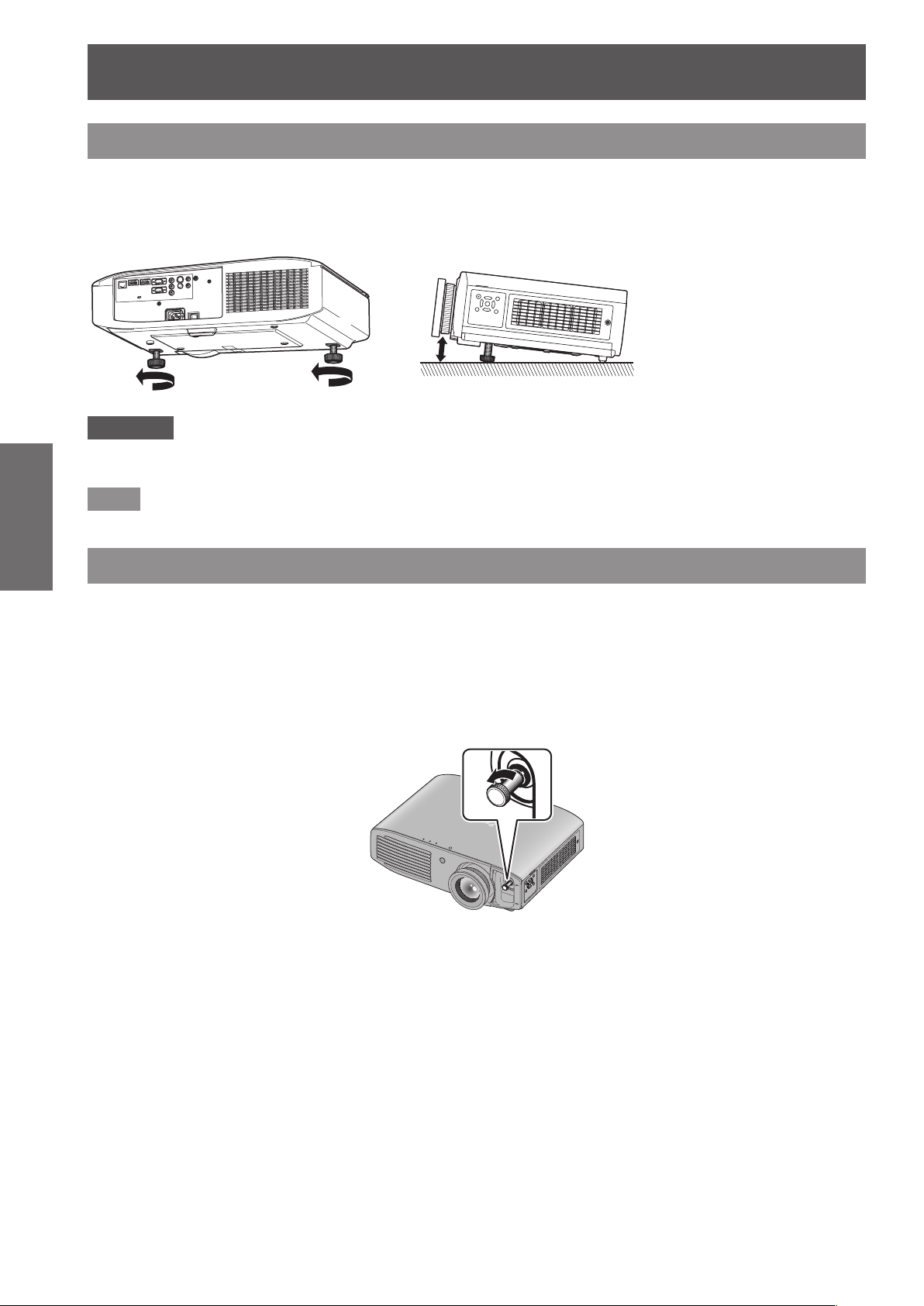
Adjusting adjustable feet
In order to make the projection screen rectangle, place the projector on a at surface with its front surface parallel
to the screen. If the screen is tilted lower, extend the adjustable feet and adjust the angle to make a rectangle
screen. If the projector is tilted horizontally, also use the adjustable feet and adjust the angle to keep the projector
at. The adjustable feet can be extended by turning it as shown in the gure, and it is retracted by turning it in the
reverse direction.
Attention
Getting Started
zHeated air is expelled from the air exhaust port. Do not touch the air exhaust port directly when adjusting the
adjustable feet. (
Note
zTighten the adjustable feet until you hear them click into place.
page 22)
Adjustable range
Adjustable feet: 16 mm (5/8")
Lens shift and positioning
If the projector is not positioned right in front of the center of the screen, you can adjust the projected image
position using the lens shift function.
Adjusting the lens shift
1) Remove the lens shift cover.
Refer to “Removing the lens shift cover” (
z
2) Rotate the lens shift lever counterclockwise to release the lock.
page 22) for how to remove the lens shift cover.
28 - ENGLISH
Page 29
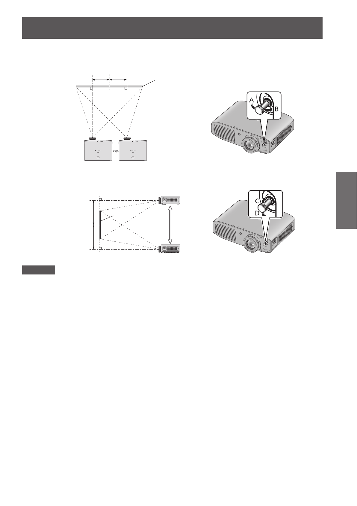
3) Adjust projection using the lens shift lever.
Up to approx. 26% of the
Up to approx. 26% of the
When adjusting the horizontal position, move the lens shift lever horizontally.
z
Setting up
projection screen
Move the lens shift lever
in direction A
When adjusting the vertical position, move the lens shift lever vertically.
z
Up to approx.
65% of the
projection screen
Up to approx.
65% of the
projection screen
projection screen
Screen
Move the lens shift lever
in direction B
Move the lens shift
lever in direction D
Screen
Move the lens shift
lever in direction C
Getting Started
Attention
zDo not force the lens shift lever. If excessive force is placed on the lever, it may break.
4) Rotate the lens shift lever clockwise to x.
5) Attach the lens shift cover.
ENGLISH - 29
Page 30
Setting up
Projector location range
The setting position can be adjusted within the following range.
Refer to “Screen size and throw distance” ( page 26) for the projection screen height (SH) and width (SW).
Projector setting range when the screen position is xed
z
Getting Started
Projector
Projector setting
range (center of lens)
Vertical center of screen
Screen
Center of lens
30 - ENGLISH
Page 31

Shift range of the projection screen when the projector position is xed
z
Shift range for projection screen
Projection position without lens shift
Setting up
Projector
Shift direction Maximum range of adjustment
Horizontal (H) Approximately 26% of the projection screen width (SW)
Vertical (V) Approximately 65% of the projection screen height (SH)
Note
zPosition the projector directly in front of the screen and move the lens shift lever to the center to obtain the
optimum projection image quality.
zWhen the lens shift lever is at the horizontal limit of the shift range, you cannot move the lever to the vertical
limit. Likewise, when the lens shift lever is at the vertical limit of the shift range, you cannot move the lever to
the horizontal limit.
zThe focus may change when the lens position is shifted out of the adjustment range. This is because the
movement of the lens is restricted to protect the optical parts.
zIf the projected image cannot be t into the screen using the lens shift function alone, adjust the projection
angle using the adjustable feet (
menu → [KEYSTONE] ( page 56).
page 28), and then correct the keystone distortion using the [POSITION]
Getting Started
ENGLISH - 31
Page 32

Connections
Connections
Before connecting to the projector
zRead carefully the instruction manual for the device to be connected.
zTurn off the power switch of the devices before connecting cables.
zIf any connection cable is not supplied with the device, or if no optional cable is available for the connection of
the device, prepare a necessary system connection cable.
zVideo signals containing too much jitter may cause the images on the screen to randomly wobble or wafture. In
this case, a time base corrector (TBC) must be connected.
zThe projector accepts video signals, S-video signals, analog RGB signals (with TTL sync. Level), and digital
signals.
zSome computer models are not compatible with the projector.
zRefer to “List of compatible signals” ( page 116) for the types of video signals that can be used with the
projector.
<S-VIDEO IN> terminal pin assignments and signal names
Getting Started
Outside view Pin No. Signal name
(1) (2)
(3) (4)
(1) GND (luminance signal)
(2) GND (color signal)
(3) Luminance signal
(4) Color signal
<COMPUTER IN> terminal pin assignments and signal names
Outside view Pin No. Signal name
(11) (15)
(1) (5)
(1) R/P
(2) G/G, SYNC/Y
(3) B/P
(10)(6) (10)(6)
(12) DDC data
(13) HD/SYNC
(14) VD
(15) DDC clock
R
B
(4) and (9) are not used.
(5) - (8), (10), and (11) are GND
terminals.
32 - ENGLISH
Page 33

Connections
<HDMI IN 1>/<HDMI IN 2> terminals pin assignments and signal names
Outside view
Even-numbered pins (2) to (18)
(2) (18)
(1) (19)
Odd-numbered pins (1) to (19)
Pin No. Signal name Pin No. Signal name
(1) T.M.D.S data 2+ (11) T.M.D.S clock shield
(2) T.M.D.S data 2 shield (12) T.M.D.S clock
(3) T.M.D.S data 2
(4) T.M.D.S data 1+ (14) —
(5) T.M.D.S data 1 shield (15) SCL
(6) T.M.D.S data 1
(7) T.M.D.S data 0+ (17)
(8) T.M.D.S data 0 shield (18) +5 V
(9) T.M.D.S data 0
(10) T.M.D.S clock+
-
-
-
(13) CEC
(16) SDA
(19) Hot plug detection
Connecting example: Input terminals
<S-VIDEO IN>/<VIDEO IN>/<COMPONENT IN> terminals
-
DDC/CEC
GND
Getting Started
To component output
DVD player
To video output
VCR
To S-video output
DVD player
ENGLISH - 33
Page 34

Connections
Computer
<LAN>/<HDMI IN 1>/<HDMI IN 2>/<COMPUTER IN>/<SERIAL>/<AUDIO
IN>/<AUDIO OUT> terminals
Blu-ray player
Getting Started
Note
zUse an HDMI High Speed cable that conforms to HDMI standards. If a cable that does not meet HDMI
standards is used, video may be interrupted or may not be displayed.
zIt is possible to connect with DVI devices via an HDMI/DVI conversion adapter, but some devices may not
project the image properly or other such problems could be encountered.
zIf [AUDIO IN SELECT] is set wrongly, the projector may not operate properly in audio output or other functions.
page 72)
(
zThis projector is not compatible with VIERA Link (HDMI).
zWhen connecting to the <SERIAL> terminal, refer to “<SERIAL> terminal” ( page 113).
zIf you operate the projector using the computer with the resume feature (last memory), you may have to reset
the resume feature to operate the projector.
To HDMI output
HDMI cable
(commercially
available)
Control computer Control computer
To RGB output
Computer cable
(commercially
available)
To audio output
To audio input
Audio system
Caution
When connecting the projector to a computer or an external device, use the power cord supplied with each
device and commercially available shielded cables.
34 - ENGLISH
Page 35

Switching on/off
Switching on/off
Connecting the power cord
Use the supplied power cord to prevent removal of the power cord and make sure that it is fully inserted
into the projector.
Conrm that the <MAIN POWER> switch is on the <OFF> side before connecting the power cord.
For detailed power cord handling, refer to “Read this rst!” ( pages 2 to 10).
Attaching
1) Check the shapes of the <AC IN> terminal on the back side of the projector and the
power cord connector and fully insert until the tabs on the left and right make a click
sound.
2) Connect the power plug to an outlet.
Removing
1) Conrm that the <MAIN POWER> switch is on the <OFF> side and unplug the power
cord from the outlet.
2) Remove the plug from the <AC IN> terminal while pushing on the tabs on the sides.
Basic Operation
ENGLISH - 35
Page 36

Switching on/off
3RZHULQGLFDWRU21*67$1'%<5!
Power indicator
The power indicator indicates the power status. Check the status of the power indicator <ON (G)/STANDBY (R)>
before operating the projector.
Indicator status Status
No illumination or ashing The main power is switched off.
When [STANDBY MODE] is set to [ECO], the power is switched off.
(The projector is in the standby mode.)
button to start projection.
button to start projection.
Red
Lit
Flashing
Press the power
zDoes not operate when the lamp indicator <LAMP> or temperature
indicator <TEMP> is ashing. ( page 97)
When [STANDBY MODE] is set to [NORMAL], the power is switched
off. (The projector is in the standby mode.)
Press the power
zDoes not operate when the lamp indicator <LAMP> or temperature
indicator <TEMP> is ashing. ( page 97)
Basic Operation
Note
zThe power
zThe projector consumes electrical power even when the power is off (when the power indicator <ON
(G)/STANDBY (R)> illuminates or ashes red). Refer to “Power consumption” ( page 118) for the power
consumption.
Green
Orange
Flashing
Lit Projecting.
Lit
Flashing
button is pressed in the power off operation, it may take some time to enter projection mode.
The projector is preparing to project.
Projection starts after a while.
The projector is preparing to switch off the power.
The power is switched off after a while. (Changes to the standby
mode.)
The power
The projector is preparing to project. Projection starts after a while.
button is pressed in the power off operation.
36 - ENGLISH
Page 37

Switching on/off
3RZHULQGLFDWRU21*67$1'%<5!
Switching on the projector
Check external device connections before switching
on the projector.
1) Connect the power cord to the
projector.
2) Connect the power plug to an outlet.
3) Press the <ON> side of the <MAIN
POWER> switch to turn on the power.
The power indicator <ON (G)/STANDBY (R)>
z
illuminates or ashes red.
4) Remove the lens cover.
Be sure to remove the lens cover before
z
starting projection.
5) Press the power button.
The power indicator <ON (G)/STANDBY (R)>
z
ashes green, and after a while, changes to
illuminate, and then projection starts.
Attention
zUsing the projector while the lens cover is attached
causes the device to heat up and can result in a
re.
zSetting the [PROJECTOR SETUP] menu → [LAMP
POWER] (
sounds.
zWhen the lamp is turned off and immediately
turned back on again, the video may temporarily
icker slightly at the start of projection due to lamp
characteristics, but his is not a malfunction.
zWhen [ECO] is selected in [STANDBY MODE]
under the [PROJECTOR SETUP] menu → [ECO
MANAGEMENT] ( page 69), the initial image may
appear about ten seconds later than when set to
[NORMAL].
zIf the direct power off function was used to set
the <MAIN POWER> switch to <OFF> during
projection, the next time the <MAIN POWER>
switch is set to <ON> with the power plug
connected to an outlet, the power indicator <ON (G)/
STANDBY (R)> will soon illuminate green and an
image will be projected. (When the [PROJECTOR
SETUP] menu → [INITIAL START UP] ( page 67)
is set to [LAST MEMORY] or [ON].)
page 68) to [ECO] reduces operation
Basic Operation
Note
zConrm that [CONTROL PANEL] (when operating
on the control panel) or [REMOTE CONTROLLER]
(when operating with the remote control) is set
to [ENABLE] from the [SECURITY] menu →
[CONTROL DEVICE SETUP] (
When you set the [SECURITY] menu, entering a
password is required. ( page 75)
zWhen switching on the projector, a small rattling
sound may be heard or when the luminous lamp is
lit, a tinkling sound may be heard, but this is not a
malfunction.
zDuring video projection, the cooling fan operates
and makes a sound. This fan sound may change
with ambient temperature and becomes louder
when the lamp is turned on.
page 77).
ENGLISH - 37
Page 38

Switching on/off
3RZHULQGLFDWRU21*67$1'%<5!
Switching off the projector
1) Press the power button.
The power off conrmation message is
z
displayed.
2) Press
the <ENTER> button.
(Or press the power
again.)
Projection of the image will stop, and the power
z
Basic Operation
indicator <ON (G)/STANDBY (R)> on the
projector illuminates orange.
(The fan continues to operate.)
3) Wait until the power indicator <ON (G)/
STANDBY (R)> of the projector turns
red (until the fan stops).
4) Press the <OFF> side of the <MAIN
POWER> switch to turn off the power.
Note
zSelect [CANCEL] or press the <MENU> or
<RETURN> button to close the power off
conrmation message.
zThe power can also be switched off when the power
button is pressed for at least 0.5 seconds.
Do not turn on the power immediately after
z
turning it off.
In the cooling state of the luminous lamp after the
power is turned off, the lamp may not illuminate
even if the power is turned on. After the power
indicator illuminates or ashes red, turn off the
main power and then back on again. Turning on the
power while the lamp is still hot may shorten the
lamp life.
Even when the power
z
and the power is turned off, the projector
consumes power if the main power is on.
Refer to “Power consumption” (
power consumption.
to select [OK], and press
button
button is pressed
page 118) for the
Direct power off function
Even if you turn the <MAIN POWER> switch <OFF>
during projection or just after the luminous lamp turns
off, the fan will rotate using internally stored power to
cool the luminous lamp. In cases where the <MAIN
POWER> switch is not easily turned <OFF>, such as
during ceiling mount, you can safely turn off the power
by using the power breaker switch. This function also
works if a power outage occurs or if the power cable
is accidentally disconnected from the outlet right after
turning off the power.
Note
zIf projection was stopped by turning off the power
breaker switch and you turn on the power breaker
again, the power indicator <ON (G)/STANDBY (R)>
illuminates green and projection starts again.
(When the [PROJECTOR SETUP] menu → [INITIAL
START UP] (
or [ON].)
zWhen the lamp has been cooled by the direct
power off function, it may take longer than usual for
the projector to start projection again.
zConrm that the fan has stopped before packing
the projector to transport or store.
page 67) is set to [LAST MEMORY]
38 - ENGLISH
Page 39

Projecting
Check the connections of the external devices ( page 32), the connection of the power cord ( page 35), and
turn on the power ( page 37) to start projection. Select the video for projection, and adjust appearance of the
projected image.
Projecting
Selecting the input signal
Select an input signal.
1) Switch on the external devices.
Press the play button on an external device, such as a Blu-ray player. When the [DISPLAY OPTION] menu
z
[SIGNAL SEARCH] (
→
and starts projection.
2) Press the input selection (<COMPUTER>, <COMPONENT>, <VIDEO/S-VIDEO>, and
<HDMI 1/2>) buttons on the remote control or press the <INPUT SELECT> button on
the control panel.
Image for a signal input to the selected terminal is projected.
z
Attention
zImages may not be projected properly depending on the external device or Blu-ray disc, DVD, etc. to be played
back. Set [TV-SYSTEM] (
zConrm the aspect ratio of the projection screen and the image, and switch to an optimum aspect ratio from
the [POSITION] menu → [ASPECT] (
page 64) is set to [ON], the projector automatically searches for an input signal
page 55), [RGB/YCBCR]/[RGB/YPBPR] ( page 55) from [PICTURE].
page 58).
Adjusting the image
1) Adjust the angle of the projector.
Place the projector parallel to the screen, and then install it on a at surface so that the screen becomes
z
rectangle.
If the screen is tilted lower than the screen, extend the adjustable feet to make a rectangle screen.
z
Refer to “Adjusting adjustable feet” (
z
2) Remove the lens shift cover.
Refer to “Removing the lens shift cover” (
z
page 28) for details.
page 22) for details.
Basic Operation
ENGLISH - 39
Page 40

Projecting
Focus ring
3) Rotate the lens shift lever counterclockwise to release the lock.
4) Adjusts lens shift.
Adjust the projection position with the lens shift lever.
z
Refer to “Lens shift and positioning” (
z
page 28) for details.
Basic Operation
5) Rotate the lens shift lever clockwise to x.
6) Attach the lens shift cover.
7) Adjust the zoom and focus.
Turn zoom ring and focus ring to adjust.
z
Note
zIt is recommended that the images are projected continuously for at least 30 minutes before the focus is
adjusted.
zAs the projection screen size changes if the focus ring is turned, turn the zoom ring to ne-tune the projection
screen size again.
Zoom ring
40 - ENGLISH
Page 41

Remote control operation
Using the Freeze function
You can freeze the projected image and stop the
sound temporarily, regardless of the playing condition
of the external device.
1) Press the <FREEZE> button on the
remote control.
z
2) Press the <FREEZE> button again.
z
Note
z[FREEZE] is displayed on the screen while the
freeze function is enabled.
Remote control operation
button
The image disappears and the sound is muted.
The image and sound resume.
Using the AV mute function
If the projector is not used for a certain period of time
during the meeting intermission, for example, this
function enables you to mute the sound and hide
images temporarily.
button
1) Press the <AV MUTE> button on the
remote control.
The image disappears and the sound is muted.
z
2) Press the <AV MUTE> button again.
The image and sound resume.
z
Note
zThe projector is not equipped with an internal
speaker. The audio is output from the external
audio system connected to the <AUDIO OUT>
terminal.
Basic Operation
ENGLISH - 41
Page 42

Remote control operation
Switching the input
The input for projection can be switched.
Press the input selection (<COMPUTER>,
<COMPONENT>, <VIDEO/S-VIDEO>,
and <HDMI 1/2>) buttons on the remote
control.
<COMPUTER>
<COMPONENT>
Basic Operation
<VIDEO/
S-VIDEO>
<HDMI 1/2>
button
Switches to computer signal input
mode.
Switches to component (YCBCR/
YPBPR) signal input mode.
Switches to S-video/video signal
input mode. If either of the input
modes has already been selected,
switches to another input mode.
Switches to HDMI signal input
mode. If either of the input modes
has already been selected,
switches to another input mode.
Using the Automatic setup function
During signal input from a computer, [SHIFT], [DOT
CLOCK], and [CLOCK PHASE] can be adjusted
automatically.
button
Press the <AUTO SETUP> button on the
remote control.
Note
zDuring HDMI signal input, only [SHIFT] is adjusted
automatically.
zThe input search is activated when there is no
signal. (When [SIGNAL SEARCH] (
to [ON])
zWhen signals exceeding the dot clock 162 MHz
are input, [DOT CLOCK] ( page 57) and [CLOCK
PHASE] ( page 57) cannot be set automatically.
zWhen you activate the auto setup function on
images with blurred edges or dark images,
operation may automatically stop. In this case,
switch to a different image and press the <AUTO
SETUP> button again.
z[AUTO SETUP] is displayed on the screen while
the image is adjusted automatically.
page 64) is set
Note
zEach time you press the <INPUT SELECT> button,
the settings change as follows. (
[HDMI 1] [HDMI 2] [COMPUTER]
[VIDEO] [S-VIDEO] [COMPONENT]
page 23)
42 - ENGLISH
Page 43

Remote control operation
Using the Function button
The <FUNC1> to <FUNC3> buttons on the remote
control can be assigned to any frequent operations to
be used as shortcut buttons.
FUNC1 FUNC2 FUNC3
button
Press the <FUNC1> to <FUNC3> button
on the remote control.
To assign functions to the
<FUNC1> to <FUNC3> buttons
1) Press the <MENU> button on the
remote control or the projector to
select a menu option (main menu, submenu, or advanced menu).
Refer to “Navigating through the menu”
z
page 44) for on-screen menu operations.
(
2) Hold down any of the <FUNC1> to
<FUNC3> buttons on the remote
control for at least three seconds.
Resetting to the factory default
Returns the settings for sub-menu or adjustment
values to the factory default.
button
Press the <DEFAULT> button on the
remote control.
Note
zRefer to “To reset to the factory default” (
for details.
page 45)
Adjusting the volume
Adjusts the volume of the audio output.
button
Note
zWhen the setting is complete, the assigned menu
item appears on the right of the remote control
operation guidance area on the lower part of the
menu screen.
Using the ECO management function
Displays the setting screen for the ECO management.
button
Press the <ECO> button on the remote
control.
Note
zFor details, refer to the [PROJECTOR SETUP]
menu → [ECO MANAGEMENT] (
page 69).
Press the <VOLUME +> or <VOLUME ->
button on the remote control.
<VOLUME +> Increases the volume.
-
<VOLUME
> Decreases the volume.
Basic Operation
ENGLISH - 43
Page 44

Menu navigation
Menu navigation
The on-screen menu (Menu) is used to perform various settings and adjustments of the projector.
Navigating through the menu
Operating procedure
button
1) Press the <MENU> button on the
remote control or the control panel.
The main menu screen is displayed.
z
PICTURE MODE
PICTURE
CONTRAST
BRIGHTNESS
COLOR
TINT
SHARPNESS
COLOR TEMPERATURE
DYNAMIC IRIS
WAVEFORM MONITOR
ADVANCED MENU
DAYLIGHT VIEW
DIGITAL CINEMA REALITY
NOISE REDUCTION
RGB/YC
BCR
to select the main menu
PROJECTOR SETUP
2) Press
POSITION
LANGUAGE
DISPLAY OPTION
SECURITY
NETWORK
item.
The selected item is highlighted in yellow.
z
The sub-menu of the selected main menu item
z
is displayed on the right.
STANDARD
ON
AUTO
AUTO
3) Press the <ENTER> button.
Sub-menu items become selectable.
z
4) Press
to select the sub-menu
item, then press
settings or adjust the parameter
values.
For some items, press
z
individual adjustment screen with a bar scale as
shown in the following diagram.
KEYSTONE
For items that are only names, pressing the
z
0
0
0
0
0
<ENTER> button displays the next screen and
advanced settings can be performed.
Note
zPressing the <RETURN> or <MENU> button
when the menu screen is displayed returns to the
previous screen.
zSome items may not be adjusted or used for certain
signal formats being input to the projector.
zSome items can be adjusted even if signals are not
input.
zIndividual adjustment screen is cleared
automatically if no operation is performed for
approximately ve seconds.
zRefer to “Main menu” (
( pages 46 to 47) regarding the menu items.
to change the
to display an
0
page 46) or “Sub menu”
Settings
PICTURE
POSITION
LANGUAGE
DISPLAY OPTION
PROJECTOR SETUP
SECURITY
NETWORK
KEYSTONE
SHIFT
OVER SCAN
ASPECT
FRAME LOCK
H : V :
NORMAL
OFF
0
00
44 - ENGLISH
Page 45

To reset to the factory default
Default setting
If the <DEFAULT> button on the remote control
is pressed, the values set or adjusted in the submenu items will be restored to the factory default
settings.
button
Press the <DEFAULT> button on the
remote control.
This function differs depending on the screen
displayed.
zWhen the sub-menu screen is displayed:
The sub-menu items displayed are returned to their
default settings.
zWhen the individual adjustment screen is displayed:
Restores only the settings of the current item to the
factory default settings.
KEYSTONE
Note
zTo restore all the settings to the factory default,
refer to the [PROJECTOR SETUP] menu →
[INITIALIZE ALL] (
zSome menu items cannot be reset by pressing the
<DEFAULT> button. Adjust each item manually.
zThe mark above the bar scale in the individual
adjustment screen indicates the factory default
setting. The position of the mark varies by the
selected input signals.
page 74).
0
Menu navigation
Current setting
10
Settings
ENGLISH - 45
Page 46

Menu navigation
Main menu
There are following seven items in the main menu.
When a main menu item is selected, the screen
changes to a sub-menu selection screen.
Main menu item Page
[PICTURE] 46
[POSITION] 46
[LANGUAGE] 47
[DISPLAY OPTION] 47
[PROJECTOR SETUP] 47
[SECURITY] 47
[NETWORK] 47
Sub menu
The sub-menu screen of the selected main menu item
is displayed, and you can set and adjust the various
items in the sub-menu.
[PICTURE]
Sub-menu item
[PICTURE MODE]
[CONTRAST] 0 48
[BRIGHTNESS] 0 49
[COLOR] 0 49
[TINT] 0 49
[SHARPNESS] 0 49
[COLOR TEMPERATURE] 0 49
[DYNAMIC IRIS] [ON] 50
[WAVEFORM MONITOR] — 50
[ADVANCED MENU] — 53
[DAYLIGHT VIEW] [AUTO] 54
[DIGITAL CINEMA
REALITY]
[NOISE REDUCTION] 0
[TV-SYSTEM]
[RGB/YCBCR]*1, [RGB/YPBPR]
*1: Depends on the signal input.
*1
Factory
default
[STANDARD]*148
[ON] 54
*1
[AUTO] 55
*1
[AUTO] 55
Page
54
Settings
Note
zThe factory default settings may vary depending on
the picture mode.
zSub-menu items and factory default settings differ
depending on the selected input terminal.
[POSITION]
Sub-menu item
[KEYSTONE] 0 56
[SHIFT] 0 56
[DOT CLOCK] 0 57
[CLOCK PHASE] 0 57
[OVER SCAN] 0
[ASPECT] [NORMAL]
[FRAME LOCK] [OFF] 60
*1: Depends on the signal input.
Note
zSub-menu items and factory default settings differ
depending on the selected input terminal.
Factory
default
*1
Page
58
*1
58
46 - ENGLISH
Page 47

Menu navigation
[LANGUAGE]
Details ( page 61)
[DISPLAY OPTION]
Sub-menu item
[ON-SCREEN DISPLAY] — 62
[HDMI SIGNAL LEVEL] — 63
[CLOSED CAPTION
SETTING]
[STARTUP LOGO]
[AUTO SETUP SETTING] [AUTO] 64
[SIGNAL SEARCH] [ON] 64
[BACK COLOR] [BLUE] 65
[SXGA MODE] [SXGA] 65
[OTHER FUNCTIONS] 65
[PROJECTOR SETUP]
Sub-menu item
[STATUS] — 66
[PROJECTOR ID] [ALL] 66
[INITIAL START UP]
[PROJECTION METHOD]
[HIGH ALTITUDE MODE] [OFF] 67
[LAMP POWER] [NORMAL] 68
[LAMP RUNTIME] — 68
[SCHEDULE] [OFF] 68
[ECO MANAGEMENT] — 69
[EMULATE] [DEFAULT] 71
[FUNCTION BUTTON] — 71
[AUDIO SETTING] — 72
[DATE AND TIME] — 73
[TEST PATTERN] — 74
[INITIALIZE ALL] — 74
Factory
default
[OFF] 63
[DEFAULT
LOGO]
Factory
default
[LAST
MEMORY]
[FRONT/
DESK]
Page
64
Page
67
67
[SECURITY]
Sub-menu item
[PASSWORD] [OFF] 75
[PASSWORD CHANGE] — 75
[DISPLAY SETTING] [OFF] 76
[TEXT CHANGE] — 76
[MENU LOCK] [OFF] 76
[MENU LOCK PASSWORD] — 77
[CONTROL DEVICE SETUP] — 77
[NETWORK]
Sub-menu item
[WIRED LAN] — 78
[NAME CHANGE] — 78
[NETWORK CONTROL] [ON] 79
[STATUS] — 79
[INITIALIZE] — 79
Factory
default
Factory
default
Page
Page
Settings
ENGLISH - 47
Page 48

[PICTURE] menu
[PICTURE] menu
Select [PICTURE] from the main menu, and
select the item from the sub-menu.
Refer to “Navigating through the menu”
( page 44) for the operation of the menu
screen.
zAfter selecting the item, press
to set.
[PICTURE MODE]
You can switch to the desired picture mode suitable
for the image source and the environment in which
the projector is used.
1) Press
2) Press
button.
The [PICTURE MODE] individual adjustment
z
screen is displayed.
3) Press
The setting will change as follows each time
z
you press the button.
[STANDARD] [DYNAMIC]
to select [PICTURE MODE].
or press the <ENTER>
to switch [PICTURE MODE].
[BLACKBOARD]
Note
zThe factory default picture modes are [DYNAMIC]
for still image input signals and [STANDARD] for
movie-based input signals.
zDICOM, the abbreviation of “Digital Imaging and
Communication in Medicine”, is a standard for
medical imaging technology. Although the name
DICOM is used in the setting item, this projector
is not for a medical use. Do not use the projected
images for diagnostic purposes.
[CONTRAST]
You can adjust the contrast of the colors.
1) Press
2) Press
button.
The [CONTRAST] individual adjustment screen
z
is displayed.
3) Press
Operation Adjustment Range
Press .
Press .
to select [CONTRAST].
or press the <ENTER>
to adjust the level.
Brightens the
screen and makes
the color of image
deeper.
Darkens the screen
and makes the
color of image
lighter.
Maximum
value +64
Minimum
value
-
64
Settings
[CINEMA]
[NATURAL]
*1: When movie-based signals are input
*2: When still image signals are input
[STANDARD]
[DYNAMIC]
[BLACKBOARD]
[WHITE
BOARD]
[DICOM SIM.]
[CINEMA]
[NATURAL] The picture complies with sRGB.
*1: Set the items other than [PICTURE MODE] to the factory
default.
*1
*2
[DICOM SIM.]
The picture becomes suitable for
moving images in general.
The light output is maximized for
use in bright areas.
The picture becomes suitable for
projecting on a black board.
The picture becomes suitable for
projecting on a white board.
The picture becomes similar to
*1
that of DICOM Part 14 Grayscale
Standard.
The picture becomes suitable for
movie sources.
[WHITE BOARD]
Attention
zAdjust [BRIGHTNESS] rst when you need to
adjust [BRIGHTNESS] and [CONTRAST].
48 - ENGLISH
Page 49

[PICTURE] menu
[BRIGHTNESS]
You can adjust the dark (black) part of the projected
image.
1) Press
2) Press
to select [BRIGHTNESS].
or press the <ENTER>
button.
The [BRIGHTNESS] individual adjustment
z
screen is displayed.
3) Press
Operation Adjustment Range
Press .
Press .
to adjust the level.
Increases the
brightness of the
dark (black) parts of
the screen.
Reduces the
brightness of the
dark (black) parts of
the screen.
Maximum
value +32
Minimum
-
value
32
[COLOR]
You can adjust the color saturation of the projected
image.
1) Press
2) Press
button.
The [COLOR] individual adjustment screen is
z
displayed.
3) Press
Operation Adjustment Range
Press . Deepens colors.
Press . Weakens colors.
to select [COLOR].
or press the <ENTER>
to adjust the level.
Maximum
value +32
Minimum
-
value
32
[TINT]
You can adjust the skin tone in the projected image.
1) Press
2) Press
to select [TINT].
or press the <ENTER>
button.
The [TINT] individual adjustment screen is
z
displayed.
3) Press
Operation Adjustment Range
Press .
Press .
to adjust the level.
Adjusts skin tone
toward greenish
color.
Adjusts skin tone
toward reddish
purple.
Maximum
value +32
Minimum
-
value
32
[SHARPNESS]
You can adjust the sharpness of the projected image.
1) Press
2) Press
to select [SHARPNESS].
or press the <ENTER>
button.
The [SHARPNESS] individual adjustment
z
screen is displayed.
3) Press
Operation Adjustment Range
Press .
Press .
to adjust the level.
Contours become
sharper.
Contours become
softer.
Depends on
the signal
input.
[COLOR TEMPERATURE]
You can switch the color temperature if the white
areas of the projected image are bluish or reddish.
Settings
1) Press
to select [COLOR
TEMPERATURE].
2) Press
or press the <ENTER>
button.
The [COLOR TEMPERATURE] individual
z
adjustment screen is displayed.
3) Press
Operation Adjustment Range
Press .
Press .
to adjust the level.
Reduces red color
of the projected
image.
Reduces blue color
of the projected
image.
ENGLISH - 49
Maximum
value +6
Minimum
-
value
6
Page 50

[PICTURE] menu
Settings
[DYNAMIC IRIS]
You can switch automatic adjustment of the lamp and
the lens iris on/off. This augments the video to create
a video expression with sharp contrast between light
and shade.
1) Press
2) Press
to select [DYNAMIC IRIS].
or press the <ENTER>
button.
The [DYNAMIC IRIS] individual adjustment
z
screen is displayed.
3) Press
The setting will change as follows each time
z
you press the button.
[ON] [OFF]
[ON] Enables [DYNAMIC IRIS].
[OFF] Disables [DYNAMIC IRIS].
to switch [DYNAMIC IRIS].
[WAVEFORM MONITOR]
By using a commercial test disk etc. and setting the
luminance level of the output (luminance) signal from
a connected external device to a value within this
projector’s recommended range, you can adjust so
the display performance of the projector can be fully
leveraged.
1) Press
MONITOR].
2) Press the <ENTER> button.
The [WAVEFORM MONITOR] screen is
z
displayed.
WAVEFORM MONITOR
MONITOR POSITION
AUTO ADJUST
to select [WAVEFORM
OFF
FULL SCAN(Y)
FULL SCAN(R)
FULL SCAN(G)
FULL SCAN(B)
SINGLE LINE SCAN(Y)
SINGLE LINE SCAN(R)
SINGLE LINE SCAN(G)
SINGLE LINE SCAN(B)
UPPER RIGHT
3) Press
to select an adjustment
item, and press the <ENTER> button.
The waveform monitor is displayed.
z
[OFF] Closes the waveform monitor.
[FULL SCAN(Y)]
[FULL SCAN(R)]
[FULL SCAN(G)]
[FULL SCAN(B)]
[SINGLE LINE
SCAN(Y)]
[SINGLE LINE
SCAN(R)]
[SINGLE LINE
SCAN(G)]
[SINGLE LINE
SCAN(B)]
[MONITOR
POSITION]
[AUTO ADJUST]
Note
zSignals lower than 0% in the waveform monitor
will be displayed as same as 0% on the projected
image.
z[SINGLE LINE SCAN(Y)], [SINGLE LINE
SCAN(R)], [SINGLE LINE SCAN(G)], and [SINGLE
LINE SCAN(B)] can display horizontal lines in Y (luminance), R - (red), G - (green), and B - (blue)
from the top of the screen to the bottom more nely
than [FULL SCAN(Y)], [FULL SCAN(R)], [FULL
SCAN(G)], and [FULL SCAN(B)] and each item can
be adjusted in the same way as [FULL SCAN(Y)],
[FULL SCAN(R)], [FULL SCAN(G)], and [FULL
SCAN(B)].
zWhen selecting [SINGLE LINE SCAN(Y)], [SINGLE
LINE SCAN(R)], [SINGLE LINE SCAN(G)], or
[SINGLE LINE SCAN(B)], the display position of
the waveform can be set using
zSo that the display of individual adjustment screen
in [PICTURE] does not interfere with the waveform
monitor, the positioning of this screen differs
depending on the circumstances at the time.
z[AUTO ADJUST] is executed by pressing the
<DEFAULT> button while the waveform is
displayed. (
Checks whether each waveform
of (Y - luminance), (R - red),
(G - green), and (B - blue) for
the whole image falls within a
recommended range.
Checks whether each waveform
of (Y - luminance), (R - red), (G green), and (B - blue) falls within
a recommended range at any
horizontal lines from the upper to
the bottom of the screen.
zPress
position.
zThe waveform monitor position
changes depending on a line
position.
Sets the display position for the
input waveform at the full scan.
Set the automatic waveform
adjustment items to automatically
adjust the luminance level of the
output signal from a connected
external device.
page 52)
to move the line
.
50 - ENGLISH
Page 51

[PICTURE] menu
To adjust the waveform
Project the brightness adjustment signal of a
commercial test disk (0% (0 IRE or 7.5 IRE) - 100%
(100 IRE)) and perform adjustment.
$GMXVWWR
,PDJH
OHYHO
6LJQDOOXPLQDQFH
$GMXVWWR
:LWKFRPSXWHULQSXWH[FHSWPRYLH
EDVHGVLJQDORU>+'0,6,*1$/
/(9(/@>@
OHYHO
6LJQDOOXPLQDQFH
$GMXVWWR
6FUHHQ
SRVLWLRQ
6FUHHQ
SRVLWLRQ
GLVSOD\DEOH
DUHD
$GMXVWWR
,PDJH
GLVSOD\DEOH
DUHD
While the waveform monitor is displayed, press
the <MENU> button to adjust the waveform using
[PICTURE] of the main menu item and [ADVANCED
MENU] of the sub-menu item.
1) Adjust [FULL SCAN(Y)]/[SINGLE LINE
SCAN(Y)].
Select the [PICTURE] menu and press
z
adjust [BRIGHTNESS] and then [CONTRAST].
Adjusts the black level of the
display signal to 0% (0 IRE or
[BRIGHTNESS]
7.5 IRE).
zSetting range
-
32 to +32
Adjusts the white level of the
[CONTRAST]
display signal to 100% (100 IRE).
zSetting range
-
64 to +64
to
2) Adjust [FULL SCAN(R)]/[SINGLE LINE
SCAN(R)].
Select the [PICTURE] menu → [ADVANCED
z
MENU] and press to adjust [BRIGHTNESS
R] and then [CONTRAST R].
Adjusts the black level of the
display signal to 0% (0 IRE or
[BRIGHTNESS R]
7.5 IRE).
zSetting range
-
16 to +16
Adjusts the white level of the
[CONTRAST R]
display signal to 100% (100 IRE).
zSetting range
-
32 to +32
3) Adjust [FULL SCAN(G)]/[SINGLE LINE
SCAN(G)].
Select the [PICTURE] menu → [ADVANCED
z
MENU] and press to adjust [BRIGHTNESS
G] and then [CONTRAST G].
Adjusts the black level of the
display signal to 0% (0 IRE or
[BRIGHTNESS G]
[CONTRAST G]
7.5 IRE).
zSetting range
-
16 to +16
Adjusts the white level of the
display signal to 100% (100 IRE).
zSetting range
-
32 to +32
Settings
ENGLISH - 51
Page 52

[PICTURE] menu
4) Adjust [FULL SCAN(B)]/[SINGLE LINE
SCAN(B)].
Select the [PICTURE] menu → [ADVANCED
z
MENU] and press to adjust [BRIGHTNESS
B] and then [CONTRAST B].
Adjusts the black level of the
display signal to 0% (0 IRE or
[BRIGHTNESS B]
[CONTRAST B]
To set [MONITOR POSITION]
You can set the display position of the input waveform
during the full scan display.
Press
[UPPER LEFT]
zThe setting will change as follows each time you
press the button.
7.5 IRE).
zSetting range
-
16 to +16
Adjusts the white level of the
display signal to 100% (100 IRE).
zSetting range
-
32 to +32
to switch [MONITOR POSITION].
[UPPER CENTER]
[UPPER RIGHT]
To set [AUTO ADJUST]
The luminance level of the output signal from a
connected external device is automatically adjusted
by setting the automatic waveform adjustment items.
1) Press
to select an adjustment
item.
Automatic waveform adjustment
items
[START AUTO ADJUST] —
[BLACK LEVEL ADJUST] [ON]
[WHITE LEVEL ADJUST] [ON]
[RGB ADJUST (BLACK)] [OFF]
[RGB ADJUST (WHITE)] [OFF]
2) Press
3) Press
to switch the adjustment.
to select [START AUTO
Factory
default
ADJUST], and press the <ENTER>
button.
The [PROCESSING] message is displayed.
z
When adjustment is complete, a conrmation
message for applying results is displayed.
Settings
[LOWER RIGHT]
[UPPER LEFT]
[UPPER
CENTER]
[UPPER RIGHT]
[LOWER LEFT]
[LOWER
CENTER]
[LOWER
RIGHT]
[LOWER CENTER]
Displays the input waveform on
the upper left.
Displays the input waveform on
the upper center.
Displays the input waveform on
the upper right.
Displays the input waveform on
the lower left.
Displays the input waveform on
the lower center.
Displays the input waveform on
the lower right.
[LOWER LEFT]
4) Press
to select [OK].
5) Press the <ENTER> button.
Note
zWhen [BLACK LEVEL ADJUST] is [ON], the
display signal Y (brightness) value’s black level is
automatically adjusted to the 0% position.
zWhen [WHITE LEVEL ADJUST] is [ON], the
display signal Y (brightness) value’s white level is
automatically adjusted to the 100% position.
zWhen [RGB ADJUST (BLACK)] is [ON], the display
signal R (Red), G (Green), and B (Blue) value’s
black level are all automatically adjusted to the 0%
position.
zWhen [RGB ADJUST (WHITE)] is [ON], the display
signal R (Red), G (Green), and B (Blue) value’s
white level are all automatically adjusted to the
100% position.
zIf [WAVEFORM MONITOR] is [OFF], [AUTO
ADJUST] cannot be executed.
zProject the luminance adjustment signal of a
commercial test disk etc., and perform automatic
adjustment. However, even with an adjustment
disk, correct adjustment may not be possible if
noise is included on the disk itself or the playback
device generates noise.
52 - ENGLISH
Page 53

[PICTURE] menu
z[AUTO ADJUST] adjusts based on the 0% and
100% standard signal within the screen. Correct
adjustment cannot be performed if standard
signals are not displayed on the screen because of
overscan etc., or if a signal that is less than 0% or
greater than 100% is displayed on the screen.
[ADVANCED MENU]
You can perform more detailed adjustment in video
images.
1) Press
MENU].
2) Press the <ENTER> button.
The [ADVANCED MENU] screen is displayed.
z
3) Press
[BRIGHTNESS B].
4) Press
button.
The individual adjustment screen for each item
z
is displayed.
5) Press
[CONTRAST R]
Operation Adjustment Range
Press .
Press .
to select [ADVANCED
to select [CONTRAST R] to
or press the <ENTER>
to adjust the level.
Emphasizes red in
highlight areas.
Deemphasizes red
in highlight areas.
Maximum
value +32
Minimum
-
value
32
[BRIGHTNESS G]
Operation Adjustment Range
Press .
Press .
[BRIGHTNESS B]
Operation Adjustment Range
Press .
Press .
Emphasizes green
in shadow areas.
Deemphasizes
green in shadow
areas.
Emphasizes blue in
shadow areas.
Deemphasizes blue
in shadow areas.
Maximum
value +16
Minimum
-
value
Maximum
value +16
Minimum
value
16
-
16
[CONTRAST G]
Operation Adjustment Range
Press .
Press .
[CONTRAST B]
Operation Adjustment Range
Press .
Press .
[BRIGHTNESS R]
Operation Adjustment Range
Press .
Press .
Emphasizes green
in highlight areas.
Deemphasizes
green in highlight
areas.
Emphasizes blue in
highlight areas.
Deemphasizes blue
in highlight areas.
Emphasizes red in
shadow areas.
Deemphasizes red
in shadow areas.
Maximum
value +32
Minimum
-
value
Maximum
value +32
Minimum
value
Maximum
value +16
Minimum
value
32
-
32
-
16
Settings
ENGLISH - 53
Page 54

[PICTURE] menu
[DAYLIGHT VIEW]
You can correct the image to the optimal vividness
even if it is projected under a bright light.
1) Press
2) Press
button.
The [DAYLIGHT VIEW] individual adjustment
z
screen is displayed.
3) Press
The setting will change as follows each time
z
you press the button.
[AUTO] [ON] [OFF]
[AUTO]
[ON] Enables [DAYLIGHT VIEW].
[OFF] Disables [DAYLIGHT VIEW].
Note
zYou cannot set [AUTO] if [REAR/DESK] or [REAR/
CEILING] is selected for [PROJECTION METHOD]
of [PROJECTOR SETUP].
zThe [AUTO] mode may not function properly if an
object is placed on the top of the projector.
to select [DAYLIGHT VIEW].
or press the <ENTER>
to switch [DAYLIGHT VIEW].
Enables auto correction of
[DAYLIGHT VIEW]. The color
sensor detects the brightness
and color of the surroundings and
automatically corrects the video
display.
[DIGITAL CINEMA REALITY]
You can improve the vertical resolution of 2-2 and 2-3
pulldown video.
This function is available only with the following signal
inputs.
525i (480i), 625i (576i), 1125 (1080)/60i, 1125
(1080)/50i, S-video signal,video signal
1) Press
to select [DIGITAL CINEMA
REALITY].
2) Press
or press the <ENTER>
button.
The [DIGITAL CINEMA REALITY] individual
z
adjustment screen is displayed.
3) Press
to switch [DIGITAL CINEMA
REALITY].
The setting will change as follows each time
z
you press the button.
[ON] [OFF]
[ON]
[OFF]
Enables [DIGITAL CINEMA
REALITY].
Disables [DIGITAL CINEMA
REALITY].
[NOISE REDUCTION]
You can reduce noises when the input image is
degraded and noise is occurring in the image signal.
1) Press
REDUCTION].
to select [NOISE
Settings
2) Press
or press the <ENTER>
button.
The [NOISE REDUCTION] individual
z
adjustment screen is displayed.
3) Press
Operation Adjustment Range
Press .
Press .
Attention
zWhen this is set for an input signal with less noise,
the image may look different from what it originally
was. In such case, set the value to 0.
to adjust the level.
Strengthen the
noise reduction.
Weakens the noise
reduction.
Maximum
value +3
Minimum
value 0
54 - ENGLISH
Page 55

[PICTURE] menu
[TV-SYSTEM]
Only when the <S-VIDEO IN>/<VIDEO
z
IN> terminal is selected
The projector will automatically detect the input signal,
but if you input an unstable signal, you can set the
color system manually. Set the color system that
matches the input mode.
1) Press
2) Press
button.
The [TV-SYSTEM] screen is displayed.
z
3) Press
The setting will change as follows each time
z
you press the button.
[AUTO] [NTSC] [NTSC4.43]
[SECAM] [PAL-N] [PAL-M]
Attention
zSet it to [AUTO] normally.
zSwitch the setting to the color system for the TV
used.
Note
zSetting [AUTO] will automatically select [NTSC],
[NTSC4.43], [PAL], [PAL-M], [PAL-N], [SECAM], or
[PAL60].
to select [TV-SYSTEM].
or press the <ENTER>
to select the color system.
[PAL]
[RGB/YCBCR]/[RGB/YPBPR]
Set it to [AUTO] normally. If images are not displayed
correctly when this is set to [AUTO], set either [RGB]
or [YCBCR], [YPBPR] in accordance with the input
signal.
1) Press
[RGB/YP
2) Press
button.
The individual adjustment screen of [RGB/
z
YC
BCR
3) Press
The setting will change as follows each time
z
you press the button.
[AUTO] [RGB]
[AUTO]
[RGB] Select it for RGB signal input.
[YP
BPR
[YC
BCR
When the <COMPUTER IN>
terminal is selected
For 525i (480i), 625i (576i), 525p (480p),
z
625p (576p), and VGA60 input
Select [AUTO], [RGB], or [YCBCR].
and select [RGB/YCBCR] or
].
BPR
or press the <ENTER>
] or [RGB/YPBPR] is displayed.
to switch the setting.
[YCBCR]/
[YPBPR]
The sync signal automatically
selects the signal [RGB]/[YCBCR]/
[YPBPR].
] Select it for YPBPR signal input.
] Select it for YCBCR signal input.
For other movie-based signal input
z
Select [AUTO], [RGB], or [YPBPR].
When the <HDMI IN 1>/<HDMI IN
2> terminal is selected
For 525p (480p) and 625p (576p) input
z
Select [AUTO], [RGB], or [YCBCR].
For other movie-based signal input
z
Select [AUTO], [RGB], or [YPBPR].
Note
zRefer to “List of compatible signals” (
the signal details.
zThe signal selection may not function properly
depending on connected devices.
zIf the <COMPONENT IN> terminal is selected, the
setting cannot be congured.
page 116) for
Settings
ENGLISH - 55
Page 56

[POSITION] menu
[POSITION] menu
Select [POSITION] from the main menu, and
select the item from the sub-menu.
Refer to “Navigating through the menu”
( page 44) for the operation of the menu
screen.
zAfter selecting the item, press
to set.
[KEYSTONE]
You can correct the trapezoidal distortion that occurs
when the projector is installed tilted or when the
screen is tilted.
1) Press
2) Press
button.
The [KEYSTONE] individual adjustment screen
z
is displayed.
3) Press
distortion.
to select [KEYSTONE].
or press the <ENTER>
to correct the
[SHIFT]
You can move the image position vertically or
horizontally if the image position projected on the
screen is shifted even when the relative position of the
projector and the screen is installed correctly.
1) Press
2) Press the <ENTER> button.
The [SHIFT] individual adjustment screen is
z
displayed.
3) Press
Note
zYou can also press
function.
For vertical (up and down)
adjustment
Operation Adjustment
Press .
to select [SHIFT].
to adjust the position.
The picture
position moves
up.
directly to operate this
Settings
Operation Adjustment
Press or .
Press or .
zSetting range: -32 to +32
Note
zYou can correct the distortion ±30° from the vertical
plane. However, the picture quality will degrade
and it will get harder to focus with more correction.
Install the projector so the correction will be as
small as possible.
zImage size will also change when [KEYSTONE] is
performed.
zTrapezoidal distortion may occur depending on the
lens shift position.
zAspect ratio of the image size may shift depending
on the correction or lens zoom value.
The picture
Press .
For horizontal (right and left)
position moves
down.
adjustment
Operation Adjustment
The picture
Press .
Press .
position moves to
the right.
The picture
position moves to
the left.
56 - ENGLISH
Page 57

[POSITION] menu
[DOT CLOCK]
Only for computer (RGB) signal input
z
Use this function to adjust and minimize the effect
of interference caused by projection of patterns
consisting of vertical stripes.
The projection of the following striped pattern may
cause cyclic patterns (noise). Adjust so that the
amount of interference is at a minimum.
1) Press
2) Press
button.
The [DOT CLOCK] individual adjustment
z
screen is displayed.
3) Press
The adjustment values are
z
to select [DOT CLOCK].
or press the <ENTER>
to adjust the level.
-
32 to +32.
[CLOCK PHASE]
You can adjust to achieve an optimal image when
there is a ickering image or smeared outlines.
1) Press
2) Press
button.
The [CLOCK PHASE] individual adjustment
z
screen is displayed.
3) Press
Adjustment value will change between 0 and
z
+31. Adjust so that the amount of interference
is at a minimum.
Note
zOptimal value may not be achieved if the output
from the input computer is unstable.
zTo project a signal with dot clock frequency with
162 MHz or higher, noise may not disappear even if
[CLOCK PHASE] is adjusted.
zAdjustment is not available when a 525i (480i) or
625i (576i) component (YC
zAdjustment is not available when a 525i (480i) or
625i (576i) computer (RGB) signal is input.
z[CLOCK PHASE] cannot be adjusted when a digital
signal is input.
to select [CLOCK PHASE].
or press the <ENTER>
to adjust the level.
) signal is input.
BCR
Note
zDot clock adjustment is feasible for computer (RGB)
signal input other than 525i (480i), 625i (576i), 525p
(480p), and 625p (576p).
Attention
zSet it before adjusting [CLOCK PHASE].
Settings
ENGLISH - 57
Page 58

[POSITION] menu
[OVER SCAN]
Use the following steps to make adjustments when
text and images on the periphery of the projected
image are not properly displayed.
1) Press
to select [OVER SCAN].
When still image computer (RGB)
signal is input
For 1280 x 720 input
z
[NORMAL] [S16:9] [NATIVE]
2) Press
or press the <ENTER>
button.
The [OVER SCAN] individual adjustment
z
screen is displayed.
3) Press
The adjustment values are 0 to +10.
z
Note
zThis item is not available for still image computer
(RGB) signals.
to adjust the level.
[ASPECT]
You can switch the aspect ratio of the image.
1) Press
2) Press
button.
The [ASPECT] individual adjustment screen is
z
displayed.
3) Press
The setting will change as follows each time
z
you press the button.
When S-video/video signal is
input
to select [ASPECT].
or press the <ENTER>
to switch the setting.
For VGA70, VGA85, 1280 x 768, 1280 x
z
800, WXGA+, or WSXGA+ signal input
[NORMAL] [S16:9] [H FIT]
[NATIVE] [FULL]
For WUXGA input
z
[NORMAL] [S16:9]
[FULL] [H FIT]
For other still image computer (RGB)
z
signal input
[NORMAL] [H FIT]
[NATIVE]
*1: UXGA cannot be switched to [NATIVE].
When HDMI signal is input
*1
[FULL]
Settings
[AUTO] [NORMAL] [H FIT]
[NATIVE] [FULL]
Note
z[AUTO] is enabled only when an NTSC signal is
input for both S-video and video signals.
For 1125 (1080)/60i, 1125 (1080)/50i,
z
1125 (1080)/60p, 1125 (1080)/50p, 1125
(1080)/24p input
[NORMAL] [S16:9]
For 750 (720)/60p, 750 (720)/50p input
z
[NORMAL] [S16:9] [NATIVE]
For 525p (480p), 625p (576p) input
z
[NORMAL] [H FIT]
[NATIVE] [FULL]
58 - ENGLISH
Page 59

[POSITION] menu
For component (YC
BCR
/YPBPR)
signal/movie-based computer
(RGB) signal input
For 1125 (1080)/60i, 1125 (1080)/50i,
z
1125 (1080)/60p, 1125 (1080)/50p, 1125
(1080)/24p input
[NORMAL] [S16:9]
For 750 (720)/60p, 750 (720)/50p input
z
[NORMAL] [S16:9] [NATIVE]
For 525i (480i) (YC
z
[AUTO] [NORMAL] [H FIT]
[NATIVE] [FULL]
For 525i (480i) (RGB), 625i (576i), 525p
z
(480p), 625p (576p) input
BCR
) input
Note
zSome aspect ratios may not be available depending
on the input signal.
zIf an aspect ratio which is different from the aspect
ratio for the input signals is selected, the pictures
will appear differently from the originals.
zIf you project a copyrighted image enlarged or
distorted by using this function in commercial use
in a public place, such as a restaurant or hotel, you
might infringe on the copyright of the creator which
is protected by copyright law.
zWhen set to [AUTO], the aspect ratio is
automatically switched to the optimum aspect ratio
when an aspect ratio identier is included in the
input signal.
z[AUTO] may not be displayed if input signal is
S-video, video, or component (YC
zA black area may appear at the top and bottom of
the screen when videos that are wider than 16:9
(cinema vision etc.) are projected.
Aspect ratio Screen
/YPBPR).
BCR
Input signal
[NORMAL] [H FIT]
[NATIVE] [FULL]
Attention
zIf a 4:3 aspect video is projected at [FULL] aspect
ratio, the shape of the image may change or the
edges may not be visible. Project videos intended
by the author at the original aspect ratio.
[NORMAL]
Projects the whole
image while preserving
original ratio, using all
of either horizontal or
vertical panel pixels.
[S16:9]
Projects a 16:9 aspect
video onto a 4:3 aspect
screen.
Projection screen
Input signal
Settings
Projection screen
ENGLISH - 59
Page 60

[POSITION] menu
Aspect ratio Screen
[FULL]
The image is projected
using all the panel
(screen) pixels. The
input signals are
converted to the
aspect ratio of the
panel (screen).
[NATIVE]
The image is
projected without size
adjustment, keeping
the resolution of the
input signals.
Projection screen
Projection screen
Input signal
Input signal
[FRAME LOCK]
Only for computer (RGB) or HDMI signal
z
input
This setting is available for specic computer signals.
Set when the movie is distorted.
1) Press
2) Press
button.
The [FRAME LOCK] individual adjustment
z
screen is displayed.
3) Press
The setting will change as follows each time
z
you press the button.
[OFF] [ON]
[OFF] Disables the frame lock.
[ON] Enables the frame lock.
to select [FRAME LOCK].
or press the <ENTER>
to switch [FRAME LOCK].
Settings
[H FIT]
While the aspect ratio
is kept xed, The
image is projected
using all the panel
pixels horizontally, and
the vertical edges of
the image are cropped.
Input signal
Projection screen
60 - ENGLISH
Page 61

[LANGUAGE] menu
Select [LANGUAGE] from the main menu, and
display the sub-menu.
Refer to “Navigating through the menu”
( page 44) for the operation of the menu
screen.
zPress
the <ENTER> button to set.
Changing the display language
You can select the language of the on-screen display.
to select the language, and press
3,&785(
326,7,21
/$1*8$*(
',63/$<237,21
352-(&7256(783
6(&85,7<
1(7:25.
[LANGUAGE] menu
3,&785(
326,7,21
/$1*8$*(
',63/$<237,21
352-(&7256(783
6(&85,7<
1(7:25.
'LVSOD\HGLQDFKRVHQODQJXDJH
zVarious menus, settings, adjustment screens,
control button names, etc., are displayed in the
selected language.
zOn-screen display is available in the following
languages: German, French, Spanish, Italian,
Portuguese, Swedish, Norwegian, Danish, Polish,
Czech, Hungarian, Russian, Thai, Korean, English,
Chinese, and Japanese.
Settings
ENGLISH - 61
Page 62

[DISPLAY OPTION] menu
[DISPLAY OPTION] menu
Computer connection guidance
z
Select [DISPLAY OPTION] from the main menu,
and select the item from the sub-menu.
Refer to “Navigating through the menu”
( page 44) for the operation of the menu
screen.
zAfter selecting the item, press
to set.
Refer to the following table for key commands on the
computer for switching the image output.
Manufacturer
Panasonic
Key command to switch the
image
+
Settings
[ON-SCREEN DISPLAY]
You can set the on-screen display.
1) Press
DISPLAY].
2) Press the <ENTER> button.
The [ON-SCREEN DISPLAY] screen is
z
displayed.
3) Press
to change the setting.
[INPUT GUIDE]
You can set the display method of the name of
the input terminal displayed on the top right of the
projection screen.
zThe setting will change as follows each time you
press the button.
[DETAILED] [OFF] [SIMPLE]
[DETAILED]
[OFF] Disables the input guide.
[SIMPLE]
to select [ON-SCREEN
to select an item, and press
Displays the input terminal
graphically.
Displays the name of input
terminal currently selected.
SAMSUNG
acer
SHARP
TOSHIBA
lenovo
LG
SONY
EPSON
FUJITSU
NEC
HP
DELL
Apple
Note
zSince the method varies depending on the
computer type, refer to the user manual of your
computer.
[OSD DESIGN]
You can set the color of the menu screen (OSD).
zThe setting will change as follows each time you
press the button.
[TYPE1] [TYPE2]
[TYPE1]
[TYPE2] Sets the background color to blue.
Sets the background color to
black.
+
+
+
+
+
+ /
+ /
+ /
/ +
Note
zWhile set to [DETAILED], if signals are not input
to the <COMPUTER IN> terminal or <HDMI IN
1>/<HDMI IN 2> terminal, a guidance appears to
connect with a computer is displayed. To disable
the guidance, select [SIMPLE] or [OFF].
62 - ENGLISH
[WARNING MESSAGE]
You can set the display/hide of the warning message.
zThe setting will change as follows each time you
press the button.
[ON] [OFF]
[ON] Displays the warning message.
[OFF] Hides the warning message.
Page 63

[HDMI SIGNAL LEVEL]
You can switch the setting when the projector is
connected to an external equipment via HDMI cable
and the image is not projected correctly.
1) Press
to select [HDMI SIGNAL
LEVEL].
2) Press
to switch [HDMI SIGNAL
LEVEL].
The setting will change as follows each time
z
you press the button.
[0-1023] [64-940]
Select when the HDMI terminal
and DVI-D output terminal of an
external equipment (computer,
[0-1023]
[64-940]
Note
zThe optimal setting is different depending on the
output setting of the connected external equipment.
Refer to the instruction manual of the external
equipment regarding the output of the external
equipment.
etc.) is connected to the <HDMI
IN 1>/<HDMI IN 2> terminal of
the projector using a conversion
cable, etc.
Select when the HDMI output
terminal of an external equipment
(DVD player, etc.) is connected
to the <HDMI IN 1>/<HDMI IN 2>
terminal of the projector.
[CLOSED CAPTION SETTING]
Only for NTSC, 525i (480i) input
z
Set the closed caption display as follows.
1) Press
CAPTION SETTING].
2) Press the <ENTER> button.
The [CLOSED CAPTION SETTING] screen is
z
displayed.
to select [CLOSED
[DISPLAY OPTION] menu
[CLOSED CAPTION]
Set whether or not to display the closed caption.
zThe setting will change as follows each time you
press the button.
zWhen you set the function to [ON], a conrmation
message [If the input matches the CC type
selected,] [the SECURITY TEXT/LOGO will not be
displayed.]appears. Select [OK] or [CANCEL] and
press the <ENTER> button. You cannot set [ON] if
[CANCEL] is selected.
[OFF] [ON]
[OFF] Hides the closed caption.
[ON] Displays the closed caption.
[MODE]
Selects a closed caption mode.
zThe setting will change as follows each time you
press the button.
[CC1] [CC2]
[CC4] [CC3]
[CC1] Displays CC1 data.
[CC2] Displays CC2 data.
[CC3] Displays CC3 data.
[CC4] Displays CC4 data.
Note
zThe closed caption is a function mainly used in the
north America, and it shows the text information
contained in the image signal. Closed captions may
not be displayed on some devices or contents.
zSecurity messages set in the [SECURITY] menu →
[DISPLAY SETTING] (
when the closed caption signal of the selected
mode is input.
zPart of characters may not be displayed when high
compensation values are set in [KEYSTONE].
zClosed captions are not displayed while the menu
screen is displayed.
page 76) are not displayed
Settings
3) Press
to change the setting.
to select an item, and press
ENGLISH - 63
Page 64

[DISPLAY OPTION] menu
[STARTUP LOGO]
You can set the logo display when the power is turned
on.
1) Press
2) Press
The setting will change as follows each time
z
you press the button.
[DEFAULT
LOGO]
[DEFAULT
LOGO]
[USER LOGO]
[OFF] Disables the startup logo display.
*1: “Logo Transfer Software” is included in the attached CD-
ROM.
Note
zTo create the image for [USER LOGO], “Logo
Transfer Software” included in the supplied CDROM is required.
zThe startup logo will disappear in approximately 30
seconds.
zThe startup logo is not displayed even when
[USER LOGO] is selected, if the log has not been
transferred with “Logo Transfer Software”.
to select [STARTUP LOGO].
to switch [STARTUP LOGO].
[USER
LOGO]
Projects the Panasonic logo.
Projects the logo transferred with
“Logo Transfer Software”
[OFF]
*1
.
[AUTO SETUP SETTING]
You can set the auto setup function.
Set it to [AUTO] normally.
1) Press
to select [AUTO SETUP
SETTING].
2) Press
to switch [AUTO SETUP
SETTING].
The setting will change as follows each time
z
you press the button.
[AUTO] [BUTTON]
Enables the auto setup function
[AUTO]
[BUTTON]
Note
zThis setting is enabled only when computer or
HDMI signal is input.
when the projected signals are
switched to the computer signals.
Enables the auto setup function
only when the <AUTO SETUP>
button is pressed.(
page 42)
[SIGNAL SEARCH]
When the power is turned on, this function
automatically detects the terminal to which signals are
input and sets the function to switch.
1) Press
SEARCH].
to select [SIGNAL
Settings
2) Press
to switch [SIGNAL
SEARCH].
The setting will change as follows each time
z
you press the button.
[ON] [OFF]
[ON] Enables input detection.
[OFF] Disables input detection.
Note
zIf [ON] is set and you press the <AUTO SETUP>
button on the remote control when the selected
input is no signal, the terminal to which a signal is
input is automatically detected and switched.
64 - ENGLISH
Page 65

[DISPLAY OPTION] menu
[BACK COLOR]
You can set the color of the projected image when
there is no signal input.
1) Press
2) Press
The setting will change as follows each time
z
you press the button.
[BLUE] [BLACK]
[USER LOGO] [DEFAULT LOGO]
[BLUE]
[BLACK]
[DEFAULT
LOGO]
[USER LOGO]
*1: “Logo Transfer Software” is included in the attached CD-
ROM.
to select [BACK COLOR].
to switch [BACK COLOR].
The entire projection area appears
blue.
The entire projection area appears
black.
Projects the Panasonic logo.
Projects the logo transferred with
“Logo Transfer Software”
*1
.
[OTHER FUNCTIONS]
[AUTO SETUP]
Refer to “Using the Automatic setup function”
( page 42) for details.
[FREEZE]
You can freeze the projected image and stop
the sound temporarily, regardless of the playing
condition of the external device.
To release the setting, press the <RETURN>
button or the <FREEZE> button on the remote
control.
[AV MUTE]
You can stop the projection and the sound when
you will not be using the projector for a while.
To release the setting, press the <RETURN>
button or the <AV MUTE> button on the remote
control.
[SXGA MODE]
This function is used if the whole projected image is
not displayed when SXGA signal is input.
Set it to [SXGA] normally.
1) Press
2) Press
The setting will change as follows each time
z
you press the button.
[SXGA] [SXGA+]
[SXGA]
[SXGA+]
to select [SXGA MODE].
to switch [SXGA MODE].
When [SXGA] is set and the whole
projected image is displayed
When [SXGA] is set and the whole
projected image is not displayed
Settings
ENGLISH - 65
Page 66

[PROJECTOR SETUP] menu
[PROJECTOR SETUP] menu
Select [PROJECTOR SETUP] from the main
menu, and select the item from the sub-menu.
Refer to “Navigating through the menu”
( page 44) for the operation of the menu
screen.
zAfter selecting the item, press
to set.
[STATUS]
You can display the projector status.
1) Press
2) Press the <ENTER> button.
The [STATUS] screen is displayed.
z
[SIGNAL]
[NAME] Displays the input signal name.
[FREQUENCY]
[RUNTIME]
[PROJECTOR]
[LAMP]
to select [STATUS].
Displays the frequency of the
input signal.
Displays the operation times of
the projector.
Displays the status and the lamp
actual usage time for each mode.
[PROJECTOR ID]
The projector has an ID number setting function, and
simultaneous control or individual control is possible
with one remote control when multiple projectors are
used side by side.
1) Press
2) Press the <ENTER> button.
The [PROJECTOR ID] screen is displayed.
z
3) Press
Select one from [ALL], and [1] to [6].
z
4) Press the <ENTER> button to set it.
[PROJECTOR ID] is set.
z
Note
zThe ID number of the remote control needs to
be matched with the ID number of the projector
when the ID number is specied and individually
controlled.
zWhen the ID number is set to [ALL], the projector
will operate regardless of what ID number is
specied from the remote control or the computer.
If multiple projectors are used and some of
them have their IDs set to [ALL], they cannot be
controlled separately from the projectors with other
ID numbers.
zRefer to “Setting Remote control ID numbers”
page 24) regarding the method to set the ID
(
number on the remote control.
to select [PROJECTOR ID].
to select [PROJECTOR ID].
Settings
[SERIAL NUMBER]
[PROJECTOR]
Note
zTo estimate the lamp replacement timing, check
the lamp usage time (converted value) displayed
in [LAMP RUNTIME] (
SETUP].
zThe actual total usage time of [ECO] and [NORMAL]
may be shorter than the lamp usage time (converted
value).
Displays the serial number of the
projector.
page 68) of [PROJECTOR
66 - ENGLISH
Page 67

[PROJECTOR SETUP] menu
[INITIAL START UP]
Set the mode for start-up when the <MAIN POWER>
switch is turned <ON>.
1) Press
2) Press
The setting will change as follows each time
z
you press the button.
[LAST MEMORY]
[LAST
MEMORY]
[STANDBY] Starts up in the standby mode.
[ON] Starts projection immediately.
to select [INITIAL START UP].
to switch [INITIAL START UP].
[STANDBY] [ON]
Starts up the projector in the
mode it was in before the <MAIN
POWER> switch is turned to
<OFF>.
[PROJECTION METHOD]
You can set the projection method in accordance with
the installation status of the projector.
Change the projection method if the screen display is
upside down or inverted.
1) Press
METHOD].
2) Press
METHOD].
The setting will change as follows each time
z
you press the button.
to select [PROJECTION
to switch [PROJECTION
[HIGH ALTITUDE MODE]
If you use the projector at high elevations (1 400 m
(4 593 ft) or higher and lower than 2 700 m (8 858 ft)),
[ON] must be set.
1) Press
MODE].
2) Press
MODE].
The setting will change as follows each time
z
you press the button.
[OFF] [ON]
[OFF]
[ON]
Note
zMake sure to set this to [OFF] when you use the
projector at elevations lower than 1 400 m (4 593 ft)
above sea level, and set this to [ON] when you use
the projector at elevations of 1 400 m (4 593 ft) or
higher and lower than 2 700 m (8 858 ft). Failure to
do so may shorten the life of the internal parts and
result in malfunctions.
zDo not install the projector at elevations of 2 700 m
(8 858 ft) or higher above sea level. Failure to do so
may shorten the life of the internal parts and result
in malfunctions.
zThe speed of the fan is raised and the operation
sound will become louder when this is set to [ON].
to select [HIGH ALTITUDE
to switch [HIGH ALTITUDE
When using at a place lower than
1 400 m (4 593 ft) above sea level
When using at elevations (1 400 m
(4 593 ft) or higher and lower than
2 700 m (8 858 ft) above sea level)
[FRONT/DESK] [FRONT/CEILING]
[REAR/CEILING] [REAR/DESK]
[FRONT/DESK]
[FRONT/
CEILING]
[REAR/DESK]
[REAR/CEILING]
When installing on the desk, etc.,
in front of the screen
When installing using the ceiling
mount bracket (optional) in front of
the screen
When installing on the desk,
etc., behind the screen (using a
translucent screen)
When installing using the ceiling
mount bracket (optional) behind
the screen (using a translucent
screen)
Settings
ENGLISH - 67
Page 68

[PROJECTOR SETUP] menu
Settings
[LAMP POWER]
You can switch the electric power of projector lamp.
Set the lamp power to meet the environment and
purpose of projection.
1) Press
2) Press
The setting will change as follows each time
z
you press the button.
[NORMAL] [ECO]
[NORMAL] When high brightness is needed
[ECO]
Note
zThe [ECO] mode can reduce power consumption
and operation noise.
zThe selection made here is reected to the
indication of the “ECO setting level” in the “Multi
Projector Monitoring & Control Software” installed
from the supplied CD-ROM.
to select [LAMP POWER].
to switch [LAMP POWER].
When high brightness is not
needed
[LAMP RUNTIME]
You can display the lamp usage time (converted
value).
Attention
zWhen replacing the lamp, follow the “Replacing the
lamp unit” (
time (converted value) to 0.
Note
zWhen the lamp unit has reached the end of its life,
the lamp usage time (converted value) is indicated
in red and gray. Refer to “When to replace the lamp
unit” (
page 104) and reset the lamp usage
page 103) for details about the lifespan.
[SCHEDULE]
You can set the command execution schedule for
each day of the week.
1) Press
2) Press
The setting will change as follows each time
z
you press the button.
[OFF] [ON]
[OFF] Disables the set schedule.
[ON] Enables the set schedule.
Note
zIf [SCHEDULE] is set to [ON], the setting
for [STANDBY MODE] (
MANAGEMENT] is automatically set to [NORMAL]
and cannot be changed. Even if [SCHEDULE] is
then set to [OFF] when in this state, the setting of
[STANDBY MODE] remains at [NORMAL].
How to assign a program
3) Select [ON] in Step 2), and press the
<ENTER> button.
The [SCHEDULE] screen is displayed.
z
4) Select and assign program to each day
of week.
Press
z
You can set the program from No.1 to No.7.
z
“- - -” indicates that the program number has
not been set yet.
How to set a program
You can set up to 16 commands to each program.
3) Select [ON] in Step 2), and press the
<ENTER> button.
to select [SCHEDULE].
to switch [SCHEDULE].
page 70) in [ECO
to select the day of week, and press
to select a program number.
68 - ENGLISH
4) Press
5) Press
to select [PROGRAM EDIT].
to select a program number
to be set ([PROGRAM 1] to [PROGRAM
7]) and press the <ENTER> button.
6) Press
to select a command
number (01 to 16), and press the
<ENTER> button.
You can change the page using
z
.
Page 69

[PROJECTOR SETUP] menu
7) Press
to select [TIME] or
[COMMAND], and change the settings
according to the operation instructions
of the menu.
[TIME]
[COMMAND]
8) Press
Sets the time at which the command
will be executed using
Selects a command to execute at the
set time from the following.
[POWER ON]
[STANDBY]
[AV MUTE] [ON]
[INPUT] [COMPUTER]
[LAMP POWER] [NORMAL]
[IN STANDBY MODE] [ON]
[VOLUME]
to select [STORE], and
.
[OFF]
[VIDEO]
[S-VIDEO]
[COMPONENT]
[HDMI 1]
[HDMI 2]
[ECO]
[OFF]
press the <ENTER> button.
Note
zIf you try to register a setting that would cause the
lamp to ash for a short time, an error message will
be displayed on the screen and the setting will not
be registered. Set the time and command again.
zIf multiple commands have been set for the same
time, they are executed in chronological order
starting from the smallest command number.
zThe operating time will be the local time. (
zIf an operation is executed with the remote control
or control panel of the projector or with a control
command before the command set in [SCHEDULE]
is executed, the command set with this function
may not be executed.
page 73)
[ECO MANAGEMENT]
You can optimize lamp power and reduce the power
consumption according to the application.
1) Press
MANAGEMENT].
2) Press the <ENTER> button.
The [ECO MANAGEMENT] screen is
z
displayed.
3) Press
When [AUTO POWER SAVE] was
set in Step 3)
You can enable [AMBIENT LIGHT DETECTION],
[SIGNAL DETECTION], and [AV MUTE DETECTION]
functions.
Note
zThis setting is not available if [LAMP POWER]
page 68) is set to [ECO].
(
4) Press
SAVE].
The setting will change as follows each time
z
you press the button.
[ON] [OFF]
[ON]
[OFF]
5) Press
DETECTION], [SIGNAL DETECTION],
or [AV MUTE DETECTION].
[AMBIENT
LIGHT
DETECTION]
[SIGNAL
DETECTION]
[AV MUTE
DETECTION]
to select [ECO
to select an item.
to switch [AUTO POWER
Enables the auto power save
function.
Disables the auto power save
function.
to select [AMBIENT LIGHT
Adjusts the lamp power according
to the ambient brightness.
Drops the lamp power when no
signal is input.
Drops the lamp power in the AV
Mute mode.
Settings
6) Press
The setting will change as follows each time
z
you press the button.
[ON] [OFF]
[ON] Enables the setting.
[OFF] Disables the setting.
to switch the setting.
ENGLISH - 69
Page 70

[PROJECTOR SETUP] menu
Settings
Note
zIn the following cases, lamp power may not drop
automatically.
When [LAMP POWER] is set to [ECO]
Immediately after the lamp is turned on or
immediately after setting [LAMP POWER]
zIf [AUTO POWER SAVE] is [OFF], [AMBIENT
LIGHT DETECTION], [SIGNAL DETECTION], and
[AV MUTE DETECTION] cannot be set.
zThe selection made here is reected to the
indication of the “ECO setting level” in the “Multi
Projector Monitoring & Control Software” installed
from the supplied CD-ROM.
When [NO SIGNAL SHUT-OFF]
was set in Step 3)
The projector enters the standby mode automatically
if no signal input status maintains. You can set the
latency until the projector enters the standby mode.
4) Press
SHUT-OFF].
The setting will change as follows each time
z
you press the button.
[DISABLE] [15MIN.] [60MIN.]
[DISABLE]
[15MIN.] to
[60MIN.]
Note
zThe selection made here is reected to the
indication of the “ECO setting level” in the “Multi
Projector Monitoring & Control Software” installed
from the supplied CD-ROM.
zThe duration is set to [30MIN.] by default and after
you perform initialization.
to switch [NO SIGNAL
Disables the no signal shut-off
function.
Enables the no signal shut-off
function. Allows you to set a time
in ve minute increments.
When [STANDBY MODE] was set
in Step 3)
You can set the power consumption during the
standby.
4) Press
MODE].
The setting will change as follows each time
z
you press the button.
[ECO] [NORMAL]
[ECO]
[NORMAL]
Note
zIf [SCHEDULE] is set to [ON], the setting for
[STANDBY MODE] in [ECO MANAGEMENT] is
automatically set to [NORMAL] and cannot be
changed. Even if [SCHEDULE] is then set to [OFF]
when in this state, the setting of [STANDBY MODE]
remains at [NORMAL].
zIf set to [ECO], you cannot use network functions
when the projector is standing by. Also, you cannot
use some protocol commands from <SERIAL>
terminals. When you turn on the power, projection
of the initial image may be delayed when compared
with [NORMAL] mode operation.
zIf set to [NORMAL], you can use network functions
when the projector is standing by.
to switch [STANDBY
Restricts some functions in the
standby mode to reduce power
consumption.
Does not restrict functionality
even in the standby mode.
70 - ENGLISH
Page 71

[PROJECTOR SETUP] menu
[EMULATE]
When using the control commands for one of our
projectors that you have previously purchased
to control this projector using a computer via its
<SERIAL> input terminal, set up the function as
follows. This will allow you to use the control software
etc. designed for our existing projectors.
1) Press
2) Press the <ENTER> button.
The [EMULATE] individual adjustment screen
z
is displayed.
3) Press
[DEFAULT] LZ370 series
[D3500] D3500 series
[D4000] D4000 series
[D/W5k series]
[D/W/Z6k
series]
[L730]
[L780] L780 series, L750 series
[L735] L735 series
[L785] L785 series
[LB/W series]
[F/W series]
to select [EMULATE].
to select an item.
DX800 series, DW730 series,
D5700 series, DW5100 series,
D5600 series, DW5000 series,
D5500 series
DZ6710 series, DZ6700 series,
DW6300 series, D6000 series,
D5000 series, DZ570 series,
DW530 series, DX500 series
L730 series, L720 series,
L520 series
LB3 series, LB2 series,
LB1 series, ST10 series,
LB90 series, LW80NT series,
LB80 series, LB75 series
FW430 series, FX400 series,
FW300 series, F300 series,
F200 series, FW100 series,
F100 series
[FUNCTION BUTTON]
The functions assigned to the <FUNC1> to <FUNC3>
buttons are displayed. You can also release the
assignment settings.
To cancel assigned functions
to the <FUNC1> to <FUNC3>
buttons
1) Press
BUTTON].
2) Press the <ENTER> button.
3) Press
function button (F1 to F3) you want to
release the assignment.
4) Press the <ENTER> button.
5) When the conrmation message is
displayed, select [OK] and press the
<ENTER> button.
to select [FUNCTION
to select [DISABLE] for a
Settings
4) Press the <ENTER> button.
Note
zRefer to “<SERIAL> terminal” (
page 113).
ENGLISH - 71
Page 72

[PROJECTOR SETUP] menu
[AUDIO SETTING]
Displays the details of the audio functions.
1) Press
2) Press the <ENTER> button.
The [AUDIO SETTING] screen is displayed.
z
3) Press
press
settings.
[VOLUME]
Adjusts the volume of the speaker.
Operation Adjustment Range
Press .
Press .
[BALANCE]
You can adjust the balance of left/right audio output.
Operation Adjustment Range
Press .
Press .
to select [AUDIO SETTING].
to select an item, and
to adjust levels or change
Increases the
volume.
Decreases the
volume.
Increases the
volume from the
right.
Increases the
volume from the
left.
Maximum
value 63
Minimum
value 0
L16 to R16
[AUDIO IN SELECT]
You can select the audio input from connected
external equipment.
zThe setting will change as follows each time you
press the button.
To set [HDMI 1]
z
[HDMI 1 AUDIO IN] [AUDIO IN]
[HDMI 1 AUDIO IN]
[AUDIO IN]
To set [HDMI 2]
z
[HDMI 2 AUDIO IN] [AUDIO IN]
[HDMI 2 AUDIO IN]
[AUDIO IN]
Note
zSound is output from the device connected to the
<AUDIO IN> terminal when you have set an input
selection item other than [HDMI 1] or [HDMI 2].
Outputs HDMI 1 audio when the
HDMI 1 input is selected.
Outputs audio from the device
connected to the <AUDIO IN>
terminal when the HDMI 1 input is
selected.
Outputs HDMI 2 audio when the
HDMI 2 input is selected.
Outputs audio from the device
connected to the <AUDIO IN>
terminal when the HDMI 2 input is
selected.
Settings
[IN STANDBY MODE]
You can set the audio output during the standby.
zThe setting will change as follows each time you
press the button.
[OFF] [ON]
[OFF]
[ON]
Note
zYou cannot enable sound output during standby
if [STANDBY MODE] (
MANAGEMENT] is set [ECO].
Disables audio output during the
standby.
Enables audio output during the
standby.
page 70) of [ECO
72 - ENGLISH
Page 73

[DATE AND TIME]
You can set the time zone, date, and time of the builtin clock of the projector.
By default, the time is set to +09:00.
To set the time zone
[PROJECTOR SETUP] menu
To adjust the date and time
manually
1) Press
2) Press the <ENTER> button.
The [DATE AND TIME] screen is displayed.
z
to select [DATE AND TIME].
1) Press
to select [DATE AND TIME].
2) Press the <ENTER> button.
The [DATE AND TIME] screen is displayed.
z
3) Press
4) Press
To adjust the date and time
to select [TIME ZONE].
to switch [TIME ZONE].
automatically
1) Press
2) Press the <ENTER> button.
The [DATE AND TIME] screen is displayed.
z
3) Press
4) Press the <ENTER> button.
The [ADJUST CLOCK] screen is displayed.
z
5) Press
SYNCHRONIZATION], and press
to change the setting to [ON].
The setting will change as follows each time
z
you press the button.
[OFF] [ON]
[OFF] Does not synchronize NTP server.
[ON] Synchronizes NTP server.
to select [DATE AND TIME].
to select [ADJUST CLOCK].
to select [NTP
3) Select [ADJUST CLOCK].
4) Press the <ENTER> button.
The [ADJUST CLOCK] screen is displayed.
z
5) Press
SYNCHRONIZATION], and press
to select [NTP
to change the setting to [OFF].
6) Press
and press
to select the item to be set,
to set the local date
and time.
7) Press
to select [OK], and press
the <ENTER> button.
The setting of the date and time will be
z
completed.
Note
zTo set the date and time automatically, the projector
must be connected to the network.
zIf synchronization with the NTP server fails
just after [NTP SYNCHRONIZATION] is turned
[ON], or if [NTP SYNCHRONIZATION] is turned
[ON] while the NTP server is not set, [NTP
SYNCHRONIZATION] will return to [OFF].
zAccess the projector via a web browser to set
the NTP server. Refer to “[Adjust clock] page”
page 87) for details.
(
6) Press
to select [OK], and press
the <ENTER> button.
The setting of the date and time will be
z
completed.
Settings
ENGLISH - 73
Page 74

[PROJECTOR SETUP] menu
[TEST PATTERN]
Displays the test pattern built-in to the projector.
Settings of position, size, and other factors will not
be reected in test patterns. Make sure to display the
input signal before performing various adjustments.
1) Press
2) Press the <ENTER> button.
The test pattern is displayed.
z
3) Press
patterns.
Press the <MENU> button or the <RETURN>
z
button to return to the sub-menu of
[PROJECTOR SETUP].
To display sequence of internal
test patterns
The setting will change as follows each time you
press
All white
to select [TEST PATTERN].
to switch the various test
.
Color bars
Note
zThe default screen is all white. If you assign this to
the <FUNC1> to <FUNC3> buttons, Cross hatch
becomes the default.
[INITIALIZE ALL]
You can return various setting values to the factory
default settings.
When you perform this function, the projector enters
standby mode to initialize.
1) Press
2) Press the <ENTER> button.
[INITIALIZE ALL] is displayed.
z
Password entry is required if you have set [ON]
z
in the [SECURITY] menu → [PASSWORD]
page 75).
(
3) Press
4) Press the <ENTER> button.
The [NOW INITIALIZING...] screen appears,
z
and is followed by [POWER OFF.].
5) Press the <ENTER> button.
Key operations other than the <ENTER> button
z
and the power
this time.
6) Wait until the power indicator <ON
(G)/STANDBY (R)> of the projector
illuminates or ashes red (the fan
stops).
to select [INITIALIZE ALL].
to select [OK].
button are unavailable at
Settings
Horizontal lines
Vertical lines
Dots
White cross on black background
Black cross on white background
Cross hatch
7) Press the <OFF> side of the <MAIN
POWER> switch to turn off the power.
The initial setting screen appears the next time
z
the projector is started. (
Note
zThe projector usage time, lamp usage time, and
[NETWORK] settings are not initialized.
zAfter performing initialization, the password is
returned to its factory default and [PASSWORD] is
set to [OFF].
page 20)
74 - ENGLISH
Page 75

[SECURITY] menu
[SECURITY] menu
Select [SECURITY] from the main menu, and
select the item from the sub-menu.
Refer to “Navigating through the menu”
( page 44) for the operation of the menu
screen.
zWhen the projector is used for the rst time
Initial password: Press
order, and press the <ENTER> button.
zAfter selecting the item, press
Attention
zMake the settings after displaying the [SECURITY]
screen.
zWhen the [SECURITY] screen is displayed,
entering a password is required. Enter the set
password and then continue operations.
zWhen the password has been changed previously,
enter the changed password, and press the
<ENTER> button.
in
to set.
Note
zThe [PASSWORD] is set to [OFF] by default and
after you perform initialization.
zChange the password periodically that is hard to
guess.
zThe security password will be enabled after setting
[PASSWORD] to [ON] and turning off the power
(standby mode).
[PASSWORD CHANGE]
You can change the security password.
1) Press
CHANGE].
2) Press the <ENTER> button.
The [PASSWORD CHANGE] screen is
z
displayed.
3) Press
buttons to set the password.
Up to eight button operations can be set.
z
4) Press the <ENTER> button.
5) Re-enter the password for the
conrmation.
to select [PASSWORD
and number (<1> - <6>)
Note
zThe entered password is displayed with * mark on
the screen.
[PASSWORD]
You can set to display the security password entry
screen when the projection starts. If the correct
password is not entered, any operation other than the
power button operations becomes unavailable.
1) Press
2) Press
The setting will change as follows each time
z
you press the button.
[OFF] [ON]
[OFF]
[ON]
to select [PASSWORD].
to switch [PASSWORD].
Disables the security password
entry.
Enables the security password
entry.
6) Press the <ENTER> button.
Note
zThe entered password is displayed with * mark on
the screen.
zAn error message is displayed on the screen when
the entered password is incorrect. Re-enter the
correct password.
zWhen numerals are used in the security password,
initialization of the security password will be
necessary if the remote control is lost. For the
method of initialization, consult your dealer.
Settings
ENGLISH - 75
Page 76

[SECURITY] menu
[DISPLAY SETTING]
You can overlap the security message (text or image)
over the projecting image.
1) Press
SETTING].
2) Press
SETTING].
The setting will change as follows each time
z
you press the button.
[OFF] [TEXT]
[OFF]
[TEXT] Enables the text display.
[USER LOGO]
*1: “Logo Transfer Software” is included in the attached CD-
ROM.
Note
zTo create the image for [USER LOGO], “Logo
Transfer Software” included in the supplied CDROM is required.
zYou cannot display both security message and
closed caption at the same time.
to select [DISPLAY
to switch [DISPLAY
Disables the text/user logo
display.
Projects the logo transferred with
“Logo Transfer Software”
[USER
LOGO]
*1
.
[MENU LOCK]
You can set whether to display the menu and perform
the menu operation when you press the <MENU>
button.
1) Press
2) Press
The setting will change as follows each time
z
you press the button.
[OFF] [ON]
[OFF]
[ON] Locks the menu operation.
Note
zIf an incorrect menu lock password is entered after
[MENU LOCK] is set to [ON], the menu operation is
disabled.
zThe [MENU LOCK] is set to [OFF] by default and
after you perform initialization.
zThe unlock status is maintained until the projector
is set to the standby mode.
to select [MENU LOCK].
to switch [MENU LOCK].
Disables the lock of the menu
operation.
Settings
[TEXT CHANGE]
You can change the text displayed when the text
display is enabled by selecting [TEXT] in [DISPLAY
SETTING].
1) Press
2) Press the <ENTER> button.
The [TEXT CHANGE] screen is displayed.
z
3) Press
press the <ENTER> button to enter the
text.
Up to 22 characters can be entered.
z
4) Press
press the <ENTER> button.
The text is changed.
z
to select [TEXT CHANGE].
to select the text, and
to select [OK], and
76 - ENGLISH
Page 77

[MENU LOCK PASSWORD]
You can change the MENU LOCK PASSWORD.
1) Press
PASSWORD].
2) Press the <ENTER> button.
The [MENU LOCK PASSWORD] screen is
z
displayed.
3) Press
press the <ENTER> button to enter the
text.
Up to 16 characters can be entered.
z
4) Press
press the <ENTER> button.
Select [CANCEL] to stop.
z
Attention
zThe initial password when used for the rst time or
after initializing is “AAAA”.
zChange the password periodically that is hard to
guess.
to select [MENU LOCK
to select the text, and
to select [OK], and
[SECURITY] menu
[REMOTE CONTROLLER]
You can set the limitation on the control from
z
the remote control.
[ENABLE]
[DISABLE]
Note
zIt will not be possible to turn off the power (standby
status) if the operations of both of [CONTROL
PANEL] and [REMOTE CONTROLLER] are set to
[DISABLE].
Canceling [DISABLE] setting:
Press the <ENTER> button while holding down
the <MENU> button for at least two seconds on
the main unit controls to reset the [DISABLE]
setting on [CONTROL PANEL] to [ENABLE].
Use the control panel of the projector to change
the setting of [REMOTE CONTROLLER].
Enables the button operation from
the remote control.
Disables the button operation from
the remote control.
[CONTROL DEVICE SETUP]
You can enable/disable the button operations on the
control panel and the remote control.
1) Press
DEVICE SETUP].
2) Press the <ENTER> button.
The [CONTROL DEVICE SETUP] screen is
z
displayed.
3) Press
to change the setting.
When the conrmation message is displayed
z
after setting [DISABLE], select [OK] and press
the <ENTER> button.
[CONTROL PANEL]
You can set the limitation on the control from
z
the control panel.
[ENABLE]
[DISABLE]
to select [CONTROL
to select an item, and press
Enables the button operation from
the main unit.
Disables the button operation from
the main unit.
Settings
ENGLISH - 77
Page 78

[NETWORK] menu
[NETWORK] menu
Settings
Select [NETWORK] from the main menu, and
select the item from the sub-menu.
Refer to “Navigating through the menu”
( page 44) for the operation of the menu
screen.
zAfter selecting the item, press
to set.
[WIRED LAN]
Perform the initial setting of the network before using
the network function.
1) Press
2) Press the <ENTER> button.
The [WIRED DETAILED SETUP] screen is
z
displayed.
3) Press
change the settings according to the
operation instructions of the menu.
[DHCP]
[IP ADDRESS]
[SUBNET
MASK]
[DEFAULT
GATEWAY]
to select [WIRED LAN].
to select an item, and
Set the item to [ON] when using
a DHCP server to automatically
acquire the IP address. Set to
[OFF] when not using a DHCP
server.
Enter the IP address when not
using a DHCP server.
Enter the subnet mask when not
using a DHCP server.
Enter the default gateway address
when not using a DHCP server.
Note
zWhen using a DHCP server, conrm that the DHCP
server is running.
zConsult your network administrator regarding the IP
address, subnet mask, and default gateway.
zThe following settings are applied by default.
[DHCP] [OFF]
[IP ADDRESS] 192.168.10.100
[SUBNET MASK] 255.255.255.0
[DEFAULT GATEWAY] 192.168.10.1
[NAME CHANGE]
You can change the name of the projector displayed
on the network.
1) Press
2) Press the <ENTER> button.
The [NAME CHANGE] screen is displayed.
z
3) Press
press the <ENTER> button to enter the
text.
Select [ALL DELETE] to delete all the entered
z
characters, or press the <DEFAULT> button on
the remote control to delete a character on the
cursor in the entry eld.
4) After entering the name, press
to select [OK], and press the
<ENTER> button.
To cancel the change of the name, select
z
[CANCEL] and press the <ENTER> button.
Note
zThe projector name is set to Name0000 by default.
to select [NAME CHANGE].
to select the text, and
4) Press
press the <ENTER> button.
Save the current network settings.
z
78 - ENGLISH
to select [OK], and
Page 79

[NETWORK] menu
[NETWORK CONTROL]
You can set this function to control the projector from
a computer connected via the network.
1) Press
to select [NETWORK
CONTROL].
2) Press
to switch [NETWORK
CONTROL].
Each time you press the button, the settings
z
change as follows.
[ON] [OFF]
Enables the control function from
[ON]
[OFF]
a computer connected via the
network.
Disables the control function from
a computer connected via the
network.
[STATUS]
You can display the network status of the projector.
[INITIALIZE]
You can restore the network settings to the factory
default settings.
1) Press
2) Press the <ENTER> button.
[INITIALIZE] is displayed.
z
Note
zThe security password entry is required if you have
set [ON] in the [SECURITY] menu → [PASSWORD]
page 75).
(
3) Press
the <ENTER> button.
to select [INITIALIZE].
to select [OK], and press
1) Press
to select [STATUS].
2) Press the <ENTER> button.
The [STATUS] screen is displayed.
z
Settings
ENGLISH - 79
Page 80

[NETWORK] menu
Network connections
The projector has a network function, and the following operations are available from the computer using the Web
browser control.
zSetting and adjustment of the projector
zDisplay of the projector status
zSetting of E-mail notication
“Crestron RoomView” is a system developed by Crestron Electronics, Inc. which collectively manage and
control multiple system devices connected via the network, from a computer. This projector supports “Crestron
RoomView”.
zFor details of “Crestron RoomView”, refer to the Crestron Electronics, Inc. website. (Provided only in English.)
URL http://www.crestron.com
For the download of “Crestron RoomView Express”, refer to the Crestron Electronics, Inc. website. (Provided
only in English.)
URL http://www.crestron.com/getroomview
Note
zA LAN cable is required to use the network function.
zThe information and the URL of the website may be changed or deleted without notice.
zA Web browser is required to use this function. Conrm that the Web browser can be used beforehand.
Compatible OS: Windows XP/Windows Vista/Windows 7, Mac OS X v10.4/v10.5/v10.6/v10.7
Compatible browser: Internet Explorer 7.0/8.0/9.0, Safari 4.0/5.0 or later (Mac OS)
zCommunication with an E-mail server is required to use the E-mail function. Conrm that the E-mail can be
used beforehand.
zUse a LAN cable that is straight-through or crossover*1 and compatible with category 5 or higher.
*1: Depending on the system conguration, the type of the LAN cable that can be used may be either straight-through,
crossover, or both. Consult your network administrator for the details.
zUse a LAN cable with the length of 100 m (328'1") or shorter.
Settings
Required environment for computer connection
zCheck if your computer is equipped with wired LAN beforehand.
zBefore connecting the projector to your computer, be sure to check the following settings.
Check 1: LAN cable
Is the cable connected correctly?
z
Use a LAN cable compatible with category 5 or higher.
z
Check 2: Wired LAN settings
A computer equipped with wired LAN function
Is the wired LAN function activated?
z
A computer not equipped with wired LAN function
Is the wired LAN adapter recognized correctly?
z
Is the wired LAN adapter activated?
z
Install the wired LAN adapter driver before you use the network function.
z
Refer to the instruction manual of the wired LAN adapter for the installation of the driver.
80 - ENGLISH
Page 81

[NETWORK] menu
Network settings of computer
Congure the network settings (wired LAN) of the computer.
1) Turn on the power of your computer.
2) Follow the network administrator’s instructions to congure the network settings.
If the projector is in the default settings (
z
IP address 192.168.10.100
Subnet mask 255.255.255.0
Default gateway 192.168.10.1
page 78), make the following network settings on your computer.
Accessing from the Web browser
1) Start up the Web browser on the computer.
2) Enter the IP address set on the projector into the URL entry eld of the Web browser.
3) Enter the user name and the password.
The factory default setting of the user name is user1 (user rights)/admin1 (administrator rights) and the
z
password is panasonic (lower case).
4) Click OK.
The [Projector status] page is displayed.
z
Settings
ENGLISH - 81
Page 82

[NETWORK] menu
Note
zIf you control the projector using a Web browser, set [NETWORK CONTROL] (
zDo not perform setting or control simultaneously by starting up multiple Web browsers. Do not set or control the
projector from multiple computers.
zChange the password rst. ( page 93)
zThe administrator rights allows to use all functions. The user rights allows to display only the following buttons
on the screen and use those functions: [Projector status] ( page 83), [Network status] ( page 85), [Basic
control] ( page 85), [Advanced control] ( page 86), and [Change password] ( page 93).
zAccess will be locked for few minutes when an incorrect password is entered three times consecutively.
Descriptions of items
(1) Page tab
Switches pages by clicking it.
(2) [Status]
(1)
(2)
(3)
(4)
(5)
(6)
The status of the projector is displayed by clicking this item.
(3) [Projector control]
The [Projector control] page is displayed by clicking this
item.
(4) [Detailed set up]
The [Detailed set up] page is displayed by clicking this item.
(5) [Change password]
The [Change password] page is displayed by clicking this
item.
(6) [CRESTRON RoomView]
The RoomView operation page is displayed by clicking this
item.
page 79) to [ON].
Settings
82 - ENGLISH
Page 83

[Projector status] page
Click [Status] → [Projector status].
Displays the status of the projector for the following items.
(1)
(2)
(3)
(4)
[NETWORK] menu
(1) [PROJECTOR TYPE]
(5)
(6)
(7)
(8)
(9)
(10)
(11)
(12)
(13)
(14)
Displays the type of the projector.
(2) [MAIN VERSION]
Displays the rmware version of the projector.
(3) [POWER]
Displays the power status.
(4) [PICTURE MODE]
Displays the status of the picture mode.
(5) [SERIAL NUMBER]
Displays the serial number of the projector.
(6) [NETWORK VERSION]
Displays the rmware version of the network.
(7) [AV MUTE]
Displays the status of the AV mute.
(8) [VOLUME]
Displays the status of the volume.
(9) [INPUT]
Displays the selected video input.
(10) [INTAKE AIR TEMPERATURE]
Displays the status of the intake air temperature of
the projector.
(11) [EXHAUST AIR TEMPERATURE]
Displays the status of the exhaust air temperature of
the projector.
(12) [LAMP RUNTIME]
Displays the lamp usage time (converted value).
(13) [SELF TEST]
Displays the self-diagnosis information.
(14) [PROJECTOR RUNTIME]
Displays the operation times of the projector.
ENGLISH - 83
Settings
Page 84

[NETWORK] menu
Error information page
When [Error (Detail)] is displayed on the [Projector status] screen, click it to display the error details.
The projector may go into the standby status to protect the projector depending on the contents of the
z
error.
[OK]: Normal operation
[FAILED]: Occurrence of trouble
[WARNING]: Warning
Settings
Description of problem occurrence [FAILED]:
z
Item Description
[MAIN CPU BUS]
[FAN]
[INTAKE AIR TEMPERATURE]
[EXHAUST AIR TEMPERATURE]
[LAMP REMAIN TIME]
[LAMP STATUS]
[APERTURE(CONTRAST-SHUTTER)]
[INTAKE AIR TEMP.SENSOR]
[EXHAUST AIR TEMP.SENSOR]
[BATTERY] The battery replacement is required. Consult your dealer.
[AIR FILTER]
There is a problem with the microcomputer circuitry. Consult your
dealer.
There is a problem with the fan or the fan drive circuit. Consult your
dealer.
The intake air temperature is too high. It may be used in an operating
environment where the temperature is high, such as near a heating
appliance, the intake port may be blocked, or the air lter may be
clogged.
The exhaust air temperature is too high. The air exhaust port may be
blocked, or the mode setting for using the projector at high elevations
may be wrong.
The lamp usage time has exceeded the specied time, and it is time
to replace the lamp.
The lamp has failed to turn on. Wait a while until the luminous lamp
cools off, and then turn on the power.
There is a problem with the contrast shutter circuitry. Consult your
dealer.
There is a problem with the sensor used to detect intake air
temperature. Consult your dealer.
There is a problem with the sensor used to detect exhaust air
temperature. Consult your dealer.
There is too much dust accumulated in the air lter unit.
Turn the <MAIN POWER> switch to <OFF> (
the air lter ( page 99).
page 38), and clean
84 - ENGLISH
Page 85

[Network status] page
Click [Status] → [Network status].
The current network setting status is displayed.
[Basic control] page
Click [Projector control] → [Basic control].
[NETWORK] menu
(1) [INPUT]
Switches the input mode.
(2) [VOLUME]
Adjusts the volume
(3) [PICTURE MODE]
(1)
(2)
(3)
(4)
(5)
(6)
Switches the picture mode.
(4) [AV MUTE]
Switches between on and off of the AV mute.
(5) [POWER]
Switches between off and on of the power.
(6) [CLOSED CAPTION]
Switches the setting for the closed caption.
Settings
ENGLISH - 85
Page 86

Settings
[NETWORK] menu
[Advanced control] page
Click [Projector control] → [Advanced control].
(1) [POSITION]
Operates items regarding angle of view.
(2) [PICTURE]
Operates items regarding picture quality.
(1)
(2)
[Network cong] page
Click [Detailed set up] → [Network cong].
The [CAUTION!] screen is displayed by clicking [Network cong].
z
The current settings are displayed by clicking the [Next] button.
z
The following setting change screen is displayed by clicking the [Change] button.
z
(1) [DHCP ON]/[DHCP OFF]
To enable the DHCP client function, set to [DHCP ON].
(2) [IP ADDRESS]
Enter the IP address when not using a DHCP server.
(3) [SUBNET MASK]
(1)
(2)
(3)
(4)
(5)
(6)
(7)
Enter the subnet mask when not using a DHCP server.
(4) [DEFAULT GATEWAY]
Enter the gateway address when not using a DHCP server.
(5) [DNS1]
Allowed characters for the entry of DNS 1 server address
(primary):
Numbers (0 to 9), period (.)
(Example: 192.168.0.253)
(6) [DNS2]
Allowed characters for the entry of DNS 2 server address
(secondary):
Numbers (0 to 9), period (.)
(Example: 192.168.0.254)
(7) [Back]/[Next]
Click the [Back] button to return to the original screen. The
current settings are displayed by pressing the [Next] button.
Click the [Submit] button to update the settings.
Note
zWhen you use the “Back” and “Forward” functions of your browser, a warning message “Page has Expired”
may appear. In that case, click [Network cong] again since the following operation will not be guaranteed.
86 - ENGLISH
Page 87

[NETWORK] menu
[Adjust clock] page
Click [Detailed set up] → [Adjust clock].
(1) [Time Zone]
Selects the time zone. (Factory default: GMT +09:00)
(2) [Set time zone]
(1)
(2)
(3)
(4)
(5)
(6)
(7)
Note
zThe replacement of the battery inside the projector is required when the time goes out of alignment right after
correcting the time. Consult your dealer.
Updates the time zone setting.
(3) [NTP SYNCHRONIZATION]
Set to [ON] to adjust the date and time automatically.
(4) [NTP SERVER NAME]
Enter the IP address or server name of the NTP server
when you set to adjust the date and time manually.
(To enter the server name, the setup of the DNS server is
required.)
(5) [Date]
Enter the date to be changed.
(6) [Time]
Enter the time to be changed.
(7) [Set date and time]
Updates the date and time settings.
ENGLISH - 87
Settings
Page 88

[NETWORK] menu
[Ping test] page
You can check whether the network is connected to the E-mail server, POP server, DNS server, etc.
Click [Detailed set up] → [Ping test].
(1) [Input IP address]
Enter the IP address of the server to be tested.
(2) [Submit]
Executes the connection test.
(1)
(2)
(3) Example of display when the connection has succeeded
(4) Example of display when the connection has failed
(3)
Settings
(4)
[ECO management set up] page
You can congure the settings regarding ECO management.
You can also congure the settings with [PROJECTOR SETUP] → [LAMP POWER], [PROJECTOR SETUP]
[ECO MANAGEMENT] → [AUTO POWER SAVE], [PROJECTOR SETUP] → [ECO MANAGEMENT] → [NO
→
SIGNAL SHUT-OFF] of the projector.
Click [Detailed set up] → [ECO management set up].
(1) [LAMP POWER]
Displays the setting of the lamp power.
(2) [AUTO POWER SAVE]
Selects the auto power save function.
(3) [AMBIENT LIGHT DETECTION]
(1)
(2)
(3)
(4)
(5)
(6)
(7)
Selects the setting of ambient light detection.
(4) [SIGNAL DETECTION]
Selects the setting of signal detection.
(5) [AV MUTE DETECTION]
Selects the setting of AV mute detection.
(6) [NO SIGNAL SHUT-OFF]
Selects the setting of No signal shut-off function.
(7) [Submit]
Update the settings.
88 - ENGLISH
Page 89

[NETWORK] menu
[E-mail set up] page
An E-mail message can be sent to the E-mail address setup in advance (up to two addresses) when the
problem occurred or the lamp usage time reached the specied value.
Click [Detailed set up] → [E-mail set up].
(1) [ENABLE]
(1)
(2)
(3)
(4)
(5)
(6)
Select [ENABLE] when using the E-mail function.
(2) [SMTP SERVER NAME]
Enter the IP address or the server name of the E-mail
server (SMTP). To enter the server name, the setup of the
DNS server is required.
(3) [MAIL FROM]
Enter the E-mail address of the projector. (Up to 63
characters in single byte)
(4) [MEMO]
You can enter information such as the location of the
projector that noties the sender of the E-mail. (Up to 63
characters in single byte)
(5) [MINIMUM TIME]
Change the minimum intervals for the temperature warning
mail. The default value is 60 minutes. In this case, another
E-mail will not be sent for 60 minutes after sending the
temperature warning mail even if it reaches the warning
temperature.
(6) [INTAKE AIR TEMPERATURE]
Change the temperature setting for the temperature
warning mail. A temperature warning mail is sent when the
temperature exceeds this value.
(1) [E-MAIL ADDRESS 1]
Enter the E-mail address to be sent.
(2) Settings of the conditions to send E-mail
Select the conditions to send E-mail.
[MAIL CONTENTS]:
Select either [NORMAL] or [SIMPLE].
(1)
(2)
[ERROR]:
An E-mail message is sent when an error occurred in
the self-diagnosis.
[LAMP RUNTIME]:
An E-mail message is sent when the remaining lamp
usage time has reached the value set at the right eld.
[INTAKE AIR TEMPERATURE]:
An E-mail message is sent when the intake air
temperature has reached the value set at the above
eld.
[PERIODIC REPORT]:
Place a check mark on this when E-mail is to be sent
periodically.
It will be sent on the days and time with the check mark.
Settings
ENGLISH - 89
Page 90

[NETWORK] menu
[E-mail set up] page (continued)
(1) [E-MAIL ADDRESS 2]
Enter the E-mail address to be sent when two E-mail
addresses are to be used.
Leave it blank when two E-mail addresses are not to be
used.
(2) Settings of the conditions to send E-mail
(1)
(2)
(3)
Select the conditions to send E-mail to the second E-mail
address.
[MAIL CONTENTS]:
Select either [NORMAL] or [SIMPLE].
[ERROR]:
An E-mail message is sent when an error occurred in
the self-diagnosis.
[LAMP RUNTIME]:
An E-mail message is sent when the remaining lamp
usage time has reached the value set at the right eld.
[INTAKE AIR TEMPERATURE]:
An E-mail message is sent when the intake air
temperature has reached the value set at the above
eld.
[PERIODIC REPORT]:
Place a check mark on this when E-mail is to be sent
periodically to the second E-mail address. It will be sent
on the days and time with the check mark.
(3) [Submit]
Update the settings.
Settings
90 - ENGLISH
Page 91

[NETWORK] menu
[Authentication set up] page
You can set the authentication items when POP authentication or SMTP authentication is necessary to send
an E-mail message.
Click [Detailed set up] → [Authentication set up].
(1) [Auth]
Select the authentication method specied by your
(1)
(2)
(3)
(4)
(5)
(6)
(7)
(8)
Internet service provider.
(2) [SMTP Auth]
Set when the SMTP authentication is selected.
(3) [POP server name]
Enter the POP server name. (Up to 63 characters in
single byte)
Allowed characters:
Alphanumerics (A to Z, a to z, 0 to 9)
Minus sign (-) and period (.)
(4) [User name]
Enter the user name for the POP server or the SMTP
server. (Up to 63 characters in single byte)
(5) [Password]
Enter the password for the POP server or the SMTP
server. (Up to 63 characters in single byte)
(6) [SMTP server port]
Enter the port number for the SMTP server.
(Normally 25)
(7) [POP server port]
Enter the port number for the POP server.
(Normally 110)
(8) [Submit]
Update the settings.
ENGLISH - 91
Settings
Page 92

[NETWORK] menu
Contents of mail sent
Example of E-mail sent when E-mail is set
z
The following E-mail is sent when the E-mail settings have been established.
Settings
Example of E-mail sent for an error
z
The following E-mail is sent when an error has occurred.
92 - ENGLISH
Page 93

[Command port set up] page
Set the port number used for command control.
Click [Detailed set up] → [Command port set up].
[Change password] page
Click [Change password].
(1) [COMMAND PORT]
Set the port number used for command control.
(2) [Set command port]
Update the settings.
(1)
(2)
(1) [Administrator]
Used to change the setting of [Administrator].
(2) [User]
Used to change the setting of [User].
(3) [Next]
(1)
(2)
(3)
Used to change the setting of the password.
[NETWORK] menu
z[Administrator] account
(1) [Account]
Displays the account to change.
(2) [Current] [User name]
(1)
(2)
(3)
(4)
(5)
(6)
(7)
Enter the user name before the change.
(3) [Current] [Password]
Enter the current password.
(4) [New] [User name]
Enter the desired new user name. (Up to 16 characters in
single byte)
(5) [New] [Password]
Enter the desired new password. (Up to 16 characters in
single byte)
(6) [New] [Password(Retype)]
Enter the desired new password again.
(7) [OK]
Determines the change of password.
Settings
ENGLISH - 93
Page 94

[NETWORK] menu
z[User] account
(1) [Account]
(2) [New] [User name]
(1)
(3) [New] [Password]
(2)
(3)
(4) [New] [Password(Retype)]
(4)
(5) [OK]
(5)
z[Change password] (For user rights)
Only the change of password is enabled under the user rights.
(1) [Old Password]
(2) [New Password]
(3) [Retype]
(1)
(4) [OK]
(2)
(3)
(4)
Displays the account to change.
Enter the desired new user name. (Up to 16 characters in
single byte)
Enter the desired new password. (Up to 16 characters in
single byte)
Enter the desired new password again.
Determines the change of password.
Enter the current password.
Enter the desired new password. (Up to 16 characters in
single byte)
Enter the desired new password again.
Determines the change of password.
Settings
Note
zTo change the account of the administrator, it is required to enter [User name] and [Password] in [Current].
94 - ENGLISH
Page 95

[NETWORK] menu
[CRESTRON RoomView] page
You can monitor/control the projector using RoomView.
To display the operation page of RoomView from Web Control screen, access with the administrator rights is
required. (The [CRESTRON RoomView] button is not displayed on the Web Control screen for user rights.)
When you click [CRESTRON RoomView], the RoomView operation page is displayed.
If Adobe Flash Player is not installed in your computer, or if the browser does not support Flash, this page
does not appear. In this case, return to the previous page by clicking [Back] in the operation page.
Operation page
z
(1) [Tools] [Info] [Help]
Switches the pages for tools/information/help using the tab.
(2) [POWER]
(1)
(2)
(3)
(4)
(5)
(6)
(7)
Switches between on and off of the power.
(3) [VOL DOWN] [AV MUTE] [VOL UP]
Sets the volume/AV mute.
When the power of the projector is turned off, [VOL DOWN],
[AV MUTE], and [VOL UP] are not available.
(4) [Input Select]
Sets the input selection.
When the power of the projector is turned off, this operation
is not available.
(5) Operation buttons on the menu screen
Operates on the menu screen.
(6) Freeze/image quality adjustment
Sets freeze/image quality details.
(7) [Back]
Returns to the previous page.
[Tools] page
z
Click [Tools] on the operation page.
(1) [Control System]
Sets the information required for the communication with
the controller that is connected to the projector.
(2) [User Password]
(1)
(2)
(3)
(4)
(5)
Sets the password for the user rights in the operation page
of RoomView.
(3) [Admin Password]
Sets the password for the administrator rights in the
operation page of RoomView.
(4) Network status
Displays the setting of wired LAN.
[DHCP]
Displays the value in the current setting.
[Ip Address]
Displays the value in the current setting.
[Subnet Mask]
Displays the value in the current setting.
[Default Gateway]
Displays the value in the current setting.
[DNS Server]
Displays the value in the current setting.
(5) [Exit]
Returns to the operation page.
Settings
ENGLISH - 95
Page 96

[NETWORK] menu
[Info] page
z
Click [Info] on the operation page.
(1)
(2)
(3)
[Help] page
z
Click [Help] on the operation page.
The [Help Desk] screen is displayed.
(1) [Projector Name]
Displays the name of the projector.
(2) [Mac Address]
Displays the MAC address.
(3) [Lamp Hours]
(4)
(5)
(6)
(7)
(8)
Displays the lamp usage time (converted value).
(4) [Power Status]
Displays the status of the power.
(5) [Source]
Displays the selected video input.
(6) [Lamp Mode]
Displays the lamp mode.
(7) [Error Status]
Displays the error status.
(8) [exit]
Returns to the operation page.
(1) [Help Desk]
Sends or receive messages to the administrator who uses
Crestron RoomView.
Settings
(1)
96 - ENGLISH
Page 97

<LAMP> and <TEMP> indicators
<LAMP> and <TEMP> indicators
Managing the indicated problems
If a problem should occur inside the projector, the lamp indicator <LAMP> and the temperature indicator <TEMP>
will inform you.
Manage the indicated problems as follows.
Attention
zWhen switching off the power to deal with problems, make sure to follow the procedure in “Switching off the
projector” (
Note
zCheck the status of the power supply with the power indicator <ON (G)/STANDBY (R)>. (
Lamp indicator <LAMP>
page 38).
7HPSHUDWXUHLQGLFDWRU7(03! /DPSLQGLFDWRU/$03!
page 36)
Indicator
status
Problem
Cause
Solution
*1: The lamp usage time (converted value) is displayed in the [PROJECTOR SETUP] menu → [LAMP RUNTIME] ( page 68).
Note
zIf the lamp indicator <LAMP> is still illuminating or ashing after taking the preceding measures, ask your
dealer to repair the unit.
Time to replace the lamp unit.
(
page 103)
zIs [REPLACE LAMP] displayed when
you turned on the power?
zThe indicator illuminates when the
lamp usage time (converted value)
reaches 2 800 hours.
zReplace the lamp unit. zWait a while until
Illuminating red Flashing red
Lamp circuit failure, abnormal function, or lamp unit is
damaged.
zHave you turned
on the power again
immediately after
*1
turning it off?
the luminous lamp
cools off and turn
off the main power,
and then turn on the
power again.
zLamp circuit failure,
abnormal function, or lamp
unit is damaged.
zTurn the <MAIN POWER>
switch to <OFF>
(
page 38), and consult
your dealer.
ENGLISH - 97
Maintenance
Page 98

<LAMP> and <TEMP> indicators
Temperature indicator <TEMP>
zIlluminates red during projection.
Indicator
status
Problem The temperature inside and/or outside the projector is abnormally high.
(The message [REFER TO THE “TEMP indicator” SECTION IN THE OPERATION MANUAL.]
is displayed on the projection screen.)
zFlashing red when the power is turned off (projection stops automatically).
zIs the ventilating
Cause
Solution
Note
zIf the temperature indicator <TEMP> is still illuminating or ashing after taking the preceding measures, ask
your dealer to repair the unit.
port (intake/exhaust)
blocked?
zRemove any objects
that are blocking
the ventilating port
(intake/exhaust).
zIs the room
temperature too
high?
zPlace the projector
in an environment
with temperature
and humidity as
designated in the
specications.
page 119)
(
zIs the air lter unit
clogged?
zClean or replace
the air lter unit.
( page 99)
zIs the projector used
at high elevations
1 400 m (4 593 ft) or
higher sea level?
zThe projector can
only be used for two
minutes after turning
on the power. Set
[HIGH ALTITUDE
MODE] ( page 67)
to [ON] within two
minutes of turning
on the power.
Maintenance
98 - ENGLISH
Page 99

Maintenance/replacement
Maintenance/replacement
Before maintaining/replacing the unit
zMake sure to turn off the power before maintaining or replacing the unit. ( pages 35, 38)
zWhen turning off the power, make sure to follow the procedures in “Switching off the projector” ( page 38).
Maintenance
Outer case
Wipe off dirt and dust with a soft, dry cloth.
If the dirt is persistent, soak the cloth with water and wring it thoroughly before wiping. Dry off the projector
z
with a dry cloth.
Do not use benzene, thinner, or rubbing alcohol, other solvents, or household cleaners. Using them may
z
cause deterioration of the outer case.
When using chemical treated dusters, follow the instructions.
z
Lens
If dirt or dust accumulates on the surface of the lens, it will be enlarged and projected onto the screen.
Wipe off dirt and dust off the front surface of the lens with a soft clean cloth.
Do not use a cloth that is uffy, dusty, or soaked with oil/water.
z
Do not use excessive force when wiping the lens as it is fragile.
z
Attention
zThe lens is made of glass. Impacts or excessive force when wiping may scratch its surface. Please handle with
care.
Air lter unit
If too much dust accumulates in the air lter unit, the internal temperature of the projector cannot be
maintained at the normal level. A conrmation message is displayed on the screen, and at the same time
the temperature indicator <TEMP> illuminates red. The power is cut off automatically after a while. In such a
case, clean the air lter unit.
1) Remove the air lter cover.
Use a Phillips screwdriver to turn the air lter cover xing screw until it turns freely, and then remove the air
z
lter cover.
Air filter cover fixing screw
Air filter cover
Maintenance
ENGLISH - 99
Page 100

Maintenance/replacement
Air filter unit
2) Pull out the air lter unit.
Hold the grips on the air lter unit and pull out the air lter unit from the projector.
z
Grips (arrow engraved)
• After removing the air lter unit, remove any large build ups of dirt or dust in the air lter unit bay and the
air intake port on the projector.
3) Clean the air lter unit.
Vacuum dirt and dust from the air lter unit.
z
4) Attach the air lter unit to the projector.
5) Attach the air lter cover to the projector and use a Phillips screwdriver to tighten
the air lter cover xing screw (one screw).
Attention
zMake sure that the air lter is properly attached before using the projector. If it is not properly attached, the
projector will suck in dirt and dust causing a malfunction.
zDo not use water to wash the air lter unit. Doing so decreases its ability to absorb dust.
Maintenance
Perform Step 2) in the reverse order.
z
• Insert the air lter unit into the projector in the direction of the arrow engraved into the air lter frame (
until it clicks into place.
Perform Step 1) in the reverse order.
z
)
100 - ENGLISH
 Loading...