

Panasonic PT-F100NTU, PT-F100NTE, PT-F100NTEA, PT-F100U, PT-F100E Service Manual
...
PT-F100NTU
PT-F100NTE
PT-F100NTEA
PT-F100U
PT-F100E
PT-F100EA
ORDER NO. VED0704376C0
D10
LCD Projector
© 2007 Matsushita Electric Industrial Co., Ltd. All
rights reserved. Unauthorized copying and
distribution is a violation of law.
PT-F100NTU / PT-F100NTE / PT-F100NTEA / PT-F100U / PT-F100E / PT-F100EA
2
PT-F100NTU / PT-F100NTE / PT-F100NTEA / PT-F100U / PT-F100E / PT-F100EA
3

PT-F100NTU / PT-F100NTE / PT-F100NTEA / PT-F100U / PT-F100E / PT-F100EA
CONTENTS
Page Page
1 Safety Precautions 5
1.1. General Guidelines
1.2. Leakage Current Check
1.3. UV Precaution and UHM Lamp Precautions
2 Ext Option
2.1. Procedure to enter EXT OPTION
2.2. EXT OPTION Menu and Functions
2.3. Canceling EXT OPTION
3 Self-Check Mode
3.1. Procedure to enter the self-check mode
3.2. Self Check Display and Contents
3.3. Canceling the self-check mode
4 Test Pattern
4.1. Procedure to display test patterns
4.2. Canceling the test pattern display
5 Flicker Adjustment Mode
5.1. Procedure to enter the adjustment mode
5.2. Adjustment Display and Contents
5.3. Canceling the flicker adjustment mode
6 Using the SERIAL Connector
6.1. Connection
6.2. Pin Layout and Signal Names for SERIAL Connector
6.3. Communication Settings
6.4. Control commands
6.5. Communication Cable Specifications
6.6. Signal Selector Connecting Cable Specifications
7 Disassembly Instructions
7.1. Printed Circuit Board and Main Parts Location
7.2. Removal of Upper Case
7.3. Removal of A-P.C.Board
7.4. Removal of D-P.C.Board
7.5. Removal of F-P.C.Board
7.6. Removal of G-P.C.Board
7.7. Removal of K-P.C.Board
7.8. Removal of L-P.C.Board
7.9. Removal of PI-P.C.Board
7.10. Removal of R-P.C.Board
7.11. Removal of S1-P.C.Board
7.12. Removal of S2-P.C.Board
7.13. Removal of Z-P.C.Board
7.14. Removal of B/Q-Module
7.15. Removal of P-Module
7.16. Removal of Lamp Unit
7.17. Removal of Analysis Block and Projection Lens
7.18. Removal of LCD Block
7.19. Replacement of LCD Panel (B)
10
10
10
10
11
11
11
12
12
13
13
14
14
14
14
15
15
15
15
15
16
16
17
17
17
18
18
5
5
5
6
6
6
7
7
7
8
9
9
9
9
9
9
9
9
7.20. LCD Panel Discrimination 19
7.21. LCD Panel Combination
7.22. Replacement of Incidence Polarizer (G)
7.23. Replacement of Incidence Polarizer (R and B)
7.24. Replacement of Projection Polarizer
7.25. Replacement of PBS Array (Analysis Block)
7.26. Removal of ARF (Auto Rolling Filter) Unit
7.27. Removal of ARF Drive Unit
8 Measurement and Adjustments
8.1. Adjustment Procedure Flowchart
8.2. Cautions for Adjustment
8.3. Setting Before Adjustment
8.4. Convergence Adjustment
8.5. Lighting Area Adjustment
8.6. Software for Adjustment
8.7. Flicker Adjustment
8.8. Input Level Adjustment
8.9. Model Information Setup
9 Troubleshooting
10 Int erc onnection Bloc k Diagram
10.1. Interconnection Block Diagram (1/2)
10.2. Interconnection Block Diagram (2/2)
11 Block Diagram
11.1. Power Supply
11.2. Signal Processing (1/3)
11.3. Signal Processing (2/3)
11.4. Signal Processing (3/3)
12 Schematic Diagram
12.1. A-P.C.Board (1/7)
12.2. A-P.C.Board (2/7)
12.3. A-P.C.Board (3/7)
12.4. A-P.C.Board (4/7)
12.5. A-P.C.Board (5/7)
12.6. A-P.C.Board (6/7)
12.7. A-P.C.Board (7/7)
12.8. K-P.C.Board, G-P.C.Board
12.9. B-Module (1/2)
12.10. B-Module (2/2)
13 C irc uit Boards
13.1. A-P.C.Board (Foil Side)
13.2. A-P.C.Board (Component Side)
13.3. G-P.C.Board
14 Te rm inal guide of ICs and tr ansis tors
15 Ex ploded View s
16 Replacement Parts List
19
19
20
20
21
21
21
22
22
22
22
22
24
26
28
28
29
30
43
43
44
45
45
46
47
48
49
50
51
52
53
54
55
56
57
58
59
61
61
62
63
65
66
70
4
1 Safety Precautions
1.1. General Guidelines
· For continued safety, no modification of any circuit must be
attempted.
· Unplug the power cord from the power outlet before
disassembling this projector.
· Use correctly the supplied power cord and must ground it.
· It is advisable to use an isolation transfo rmer in the AC
power line before the service.
· Be careful not to touch the rotation part (cooling fan, etc.) of
this projector when you service with the upper case
removed and the power supply turned ON.
· Observe the original lead dress during the service. If a short
circuit is found, replace all the parts overheated or
damaged by the short circuit.
· After the service, all the protective devices such as
insulation barriers, insulation papers, shields, and isolation
R-C combinations must be properly installed.
· After the service, check the leakage current to prevent the
customer from getting an electric shock.
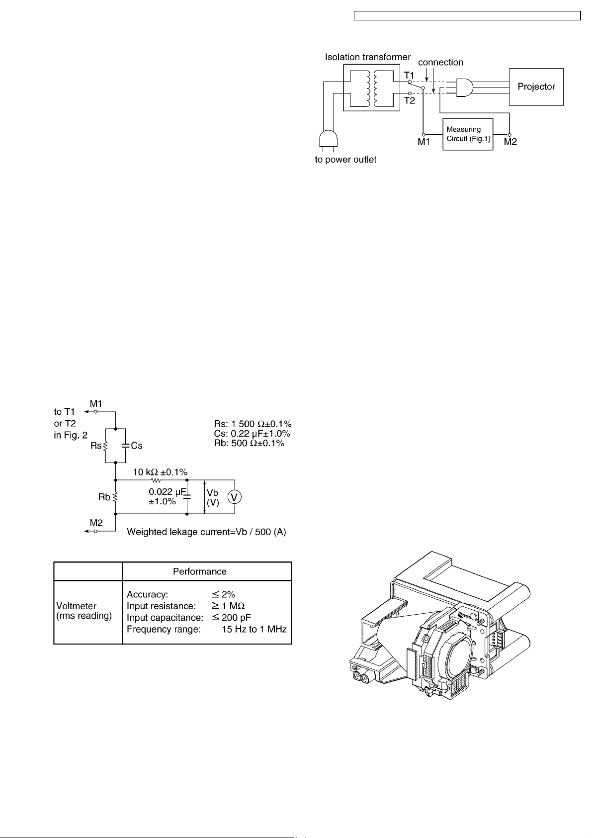
1.2. Leakage Current Check
1. Prepare the measuring circuit as shown in Fig.1.
Be sure to use a voltmeter having the performance
described in Table 1.
PT-F100NTU / PT-F100NTE / PT-F100NTEA / PT-F100U / PT-F100E / PT-F100EA
Fig. 2
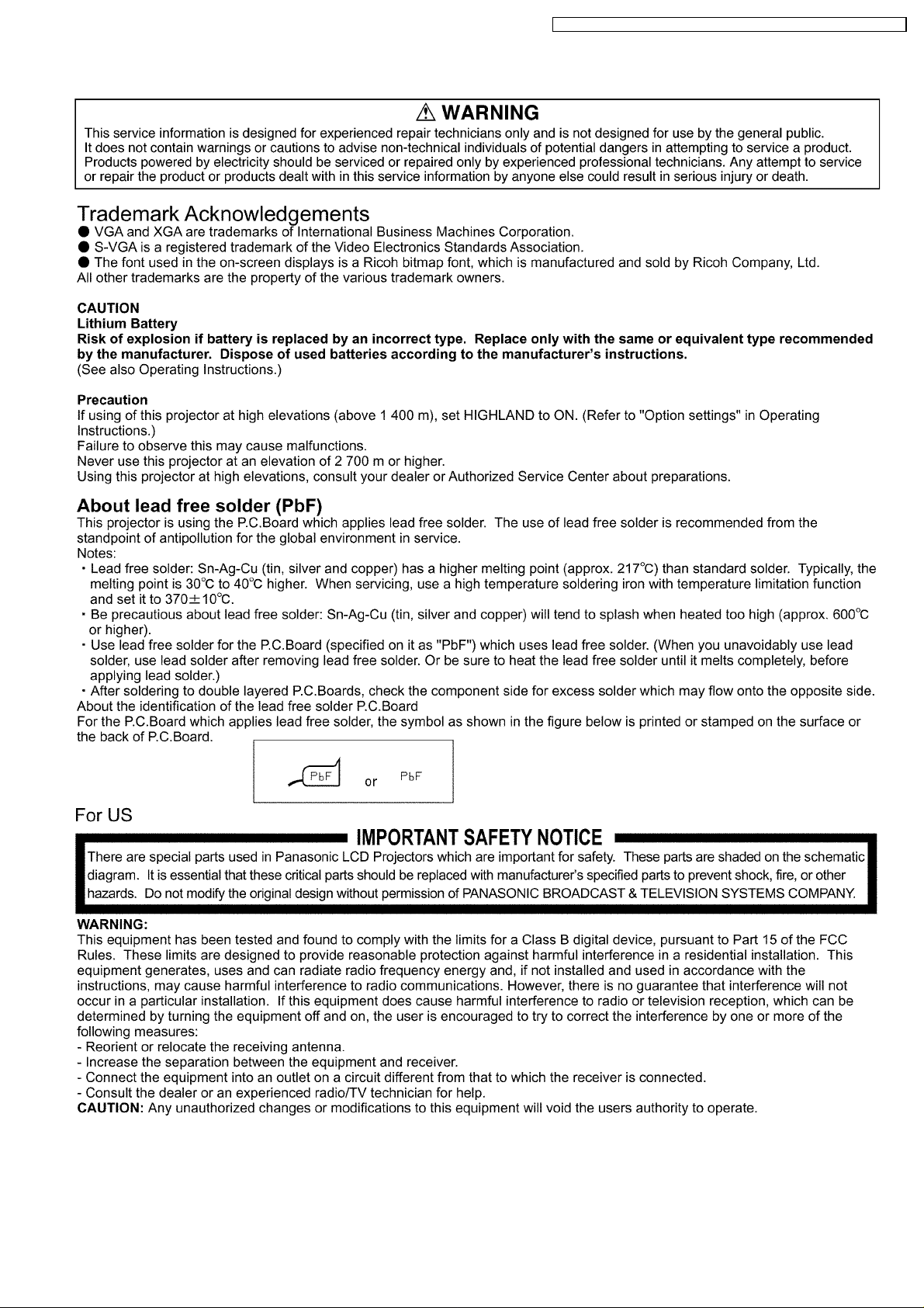
2. Assemble the circuit as shown in Fig. 2. Plug the power
cord in a power outlet.
3. Connect M1 to T1 according to Fig. 2 and measure the
voltage.
4. Change the connection of M1 from T1 to T2 and measure
the voltage again.
5. The voltmeter must read 0.375 V or lower in both of steps
3 and 4. This means that the current must be 0.75 mA or
less.
6. If the reading is out of the above standard, the projector
must be repaired and rechecked before returning to the
customer because of a possibility of an electric shock.
1.3. UV Precaution and UHM Lamp
Precautions
· Be sure to unplug the power cord from the power outlet
when replacing the lamp.
· Because the lamp reaches a very high temperature during
its operation, wait until it cools completely when replacing
the Lamp Unit.
· The lamp emits small amounts of UV-radiation, avoid directeye contact with the light.
· The lamp unit has high internal pressure. If improperly
handled, explosion might result.
· Because the high pressure lamp involves a risk of failure,
never touch the lamp wire lead during the service. (See Fig.
3)
Fig. 1
Table 1
Fig.3
5
PT-F100NTU / PT-F100NTE / PT-F100NTEA / PT-F100U / PT-F100E / PT-F100EA
2 Ext Option
This projector has EXT OPTION in addition to standard on-screen menus.
· There are SELF CHECK and TEST PATTERN for service, etc.
2.1. Procedure to enter EXT OPTION
1. Press "MENU" button on the main unit or remote control unit to display "MENU" screen, then select "OPTION" and press
"ENTER" button.
2. Select "INPUT GUIDE" on "OPTION" menu and press "ENTER" button 3 seconds or longer.
MENU → OPTION → INPUT GUIDE
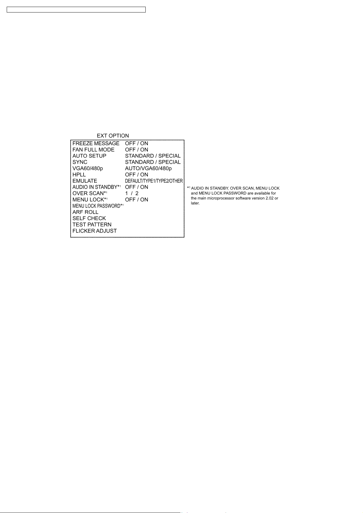
2.2. EXT OPTION Menu and Functions
· FREEZE MESSAGE
Switching ON/OFF "FREEZE" on-screen display
· FAN FULL MODE
Setting the cooling fan motor rotation speed
−
− Switching ON "FAN FULL MODE", the rotation level of the fan becomes high-speed rotation (fixed). Moreover, when "FAN
− −
FULL MODE" is ON, changing "HIGHLAND" in OPTION becomes impossible (setting "FAN FULL MODE" is given priority
more than "HIGHLAND").
· AUTOSETUP
Setting AUTO SETUP mode
−
− STANDARD: To set the normal mode (the dot clock is adjusted strictly))
− −
−
− SPECIAL: To set the special mode (the dot clock is adjusted roughly)
− −
Note:
−
− Do not change the initial setting (STANDARD).
− −
· SYNC
Setting SYNC processing mode
−
− STANDARD: To set the normal mode
− −
−
− SPECIAL: To set the special mode (noise reduction mode)
− −
Note:
−
− Do not change the setting when it is possible to receive normally.
− −
Change the setting only when the image is not displayed normally because of the sync signal noise of connected
equipment.
· VGA60/480p
−
− AUTO: Switching RGB of VGA60 and 480p automatically
− −
−
− VGA60: Inputting signals in 59.9Hz / VGA480
− −
−
− 480p: Inputting signals in RGB of 480p
− −
· HPLL
When non-standard signal of VIDEO/S-VIDEO is inputted (VTR, VHD, etc.), horizontal synchronization might be disordered
6

PT-F100NTU / PT-F100NTE / PT-F100NTEA / PT-F100U / PT-F100E / PT-F100EA
according to connected equipment. In this case, set HPLL to OFF.
· EMULATE
Switching the operation of RS-232C command to communicate with models other than F100 series.
−
− DEFAULT: F100/F100NT standard, D3500
− −
−
− TYPE1: L730/L780/L735/LB/LC series
− −
−
− TYPE2: L785
− −
−
− OTHER: Models other than the above-mentioned (Consult your dealer or Authorized Service Center for details.)
− −
· AUDIO IN STANDBY
Setting the audio output when STANDBY
−
− OFF: Does not output it.
− −
−
− ON: Outputs it.
− −
Note:
−
− When setting it to "ON", audio source of the input channel when the power supply is turned off (switched to STANDBY)
− −
is outputted. Do with the remote control unit, control panel or RS-232C communication when you switch the channel.
The audio volume can be adjusted by the remote control unit or RS-232C communication.
· OVER SCAN
Setting the rate of over scanning
−
− 1: Approx. 6%
− −
−
− 2: Approx. 4%
− −
Note:
−
− Normally, set it to "1".
− −
· MENU LOCK
Switching ON/OFF "MENU LOCK" function
−
− OFF: Accessible to MENU
− −
−
− ON: The access to MENU is restricted (The password is required).
− −
−
− When MENU LOCK is set to "ON", the password input screen is displayed when it accesses the menu, and the
− −
adjustment in the menu item is locked.
· MENU LOCK PASSWORD
Setting the password into MENU LOCK
−
− The default password is "AAAA".
− −
When you want to reset the password into the default password, do the following operation.
1. Press on the remote control unit the AUTO SETUP button, or on the main unit the INPUT SELECT button and the
button at the same time for 2 seconds or more.
2. Press
· ARF ROLL
Rolling the ARF (Auto Rolling Filter) compulsorily.
· SELF CHECK
To enter the self-check mode
· TEST PATTERN
To display test patterns
· FLICKER ADJUST
To enter the flicker adjustment mode
button for 2 seconds or more.
2.3. Canceling EXT OPTION
Press "MENU" button on the main unit or remote control unit.
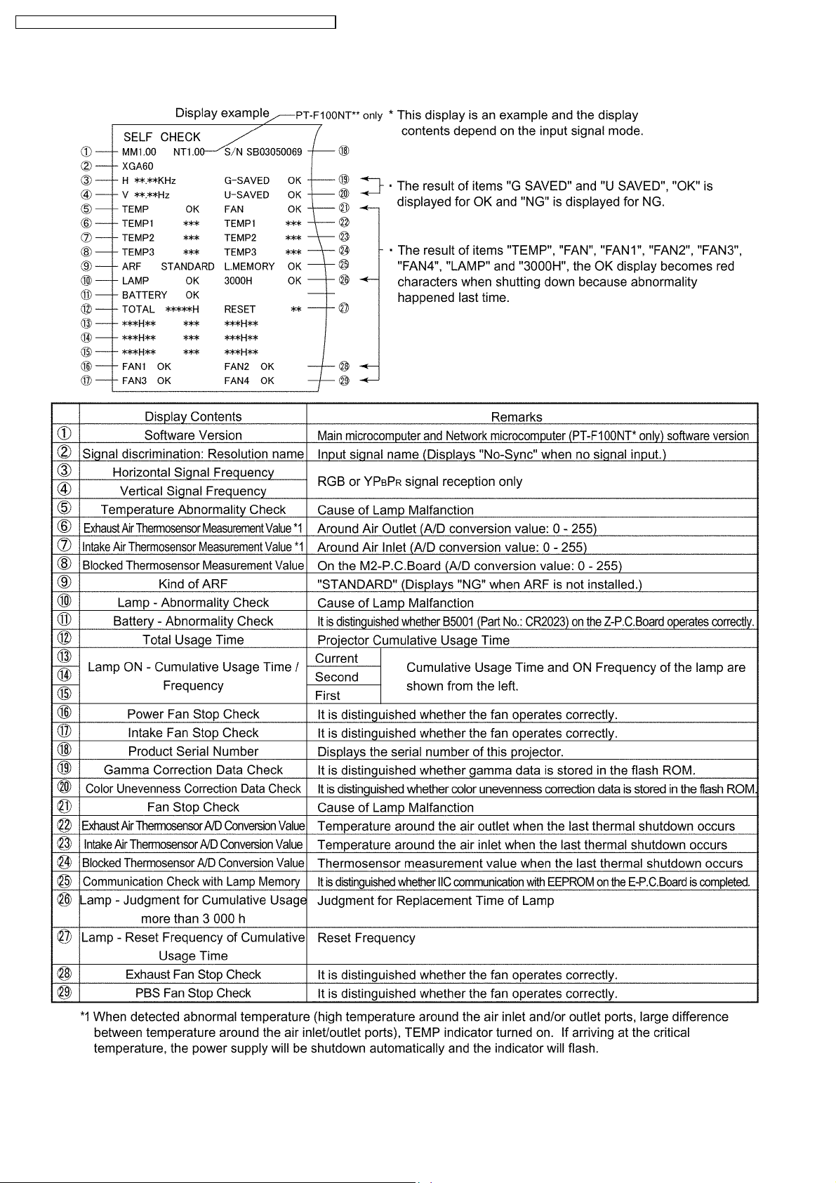
3 Self-Check Mode
This mode is used to narrow down the location of the failure.
3.1. Procedure to enter the self-check mode
Select "SELF CHECK" on "EXT OPTION" menu and press "ENTER" button on the main unit or remote control unit.
7
PT-F100NTU / PT-F100NTE / PT-F100NTEA / PT-F100U / PT-F100E / PT-F100EA
3.2. Self Check Display and Contents
8
PT-F100NTU / PT-F100NTE / PT-F100NTEA / PT-F100U / PT-F100E / PT-F100EA
3.3. Canceling the self-check mode
Press "MENU" button on the main unit or remote control unit.
4 Test Pattern
This projector displays seven kinds of test patterns [Horizontal lines, Vertical lines, Dots, Crosshatch, White cross, Black cross and
White (No pattern)] in the four colors (White, Red, Green and Blue).
Note:
· Because the above patterns can be displayed by each color without test equipment such as PC or SG, use it for simplified
adjustments by your eyes and so on.
4.1. Procedure to display test patterns
Select "TEST PATTERN" on "EXT OPTION" menu and press "ENTER" button on the main unit or remote control unit.
Note:
· On the test pattern screen, pressing the up-arrow "
the left-arrow "
" or right-arrow " " button the color selection (White / Red / Green / Blue).
4.2. Canceling the test pattern display
Press "MENU" button on the main unit or remote control unit.
" or down-arrow " " button allows the test pattern selection and
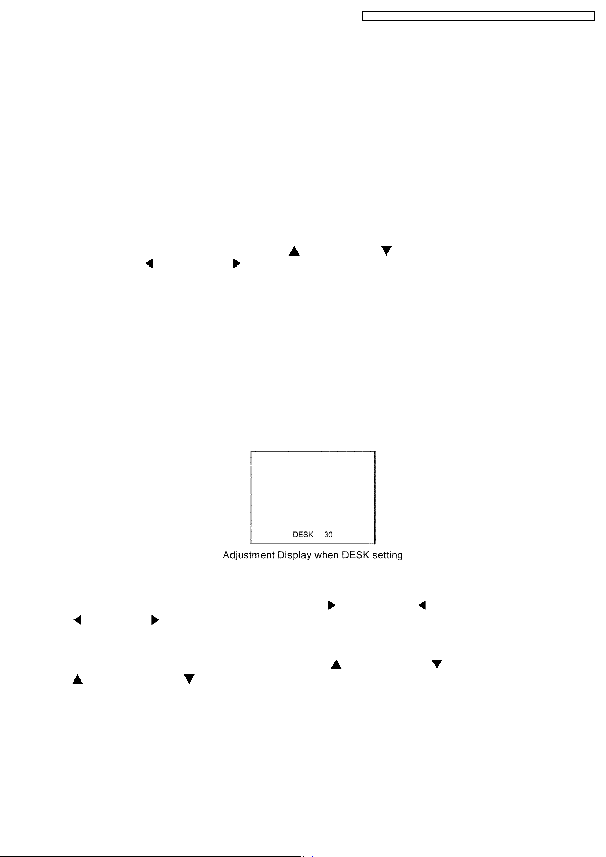
5 Flicker Adjustment Mode
If replacing the optical parts (LCD Panel / LCD block) of this projector and/or A-P.C.Board (assembly), enter the flicker adjustment
mode and minimize the flicker.
5.1. Procedure to enter the adjustment mode
Select "FLICKER ADJUST" on "EXT OPTION" menu and press "ENTER" button on the main unit or remote control unit.
Note:
"DESK setting (blue)" is displayed when entering the adjustment mode.
5.2. Adjustment Display and Contents
· Setting value is increased and decreased with the right-arrow " " and left-arrow " " button s.
"
": Decrease, " ": Increase
−
− Adjust the setting value to minimize the flicker on the screen.
− −
−
− Execute the adjustment by 6 patterns below.
− −
· The pattern (adjustment display) is switched with the up-arrow "
"
": Forward direction, " ": Reverse direction
−
− There are 6 patterns of "DESK setting (blue)", "DESK setting (red)", "DESK setting (green)", "CEILING setting (blue)",
− −
"CEILING setting (red)" and "CEILING setting (green)".
−
− The setting value is saved into this projector when the pattern is switched.
− −
" and down-arrow " " buttons.
5.3. Canceling the flicker adjustment mode
Press "MENU" button on the main unit or remote control unit.
Note:
When "MENU" button is pressed, the setting value at that time is saved into this projector and the adjustment mode is canceled.
9
PT-F100NTU / PT-F100NTE / PT-F100NTEA / PT-F100U / PT-F100E / PT-F100EA
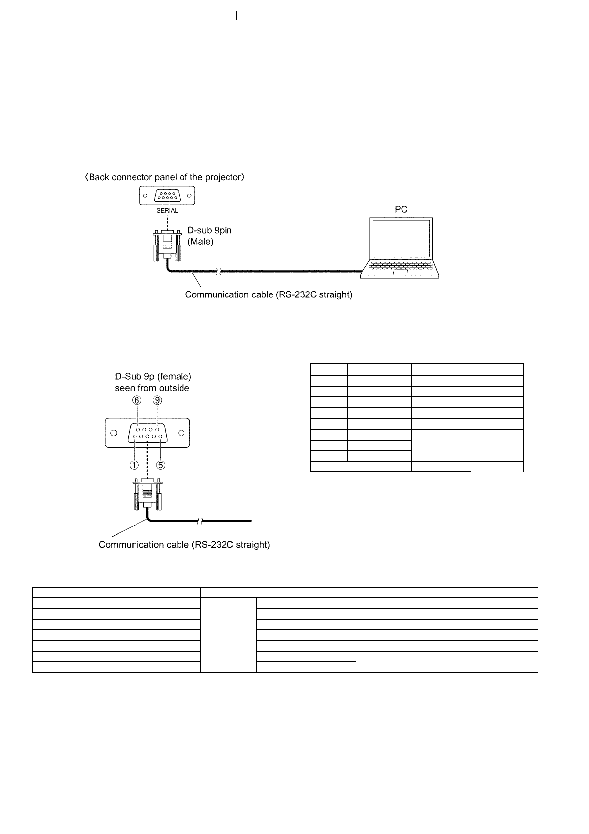
6 Using the SERIAL Connector
The serial connector which is on the back connector panel of the projector conforms to RS-232C standard. This projector can
be controlled by a PC which is connected as shown in "6.1. Connection".
For controlling this projector by a PC, requires communication software on the market, and inputs control commands according
to Communication Settings and Control Commands below.
6.1. Connection
Note:
Use a proper communication cable which is suitable for the PC to connect SERIAL connector and the PC.
6.2. Pin Layout and Signal Names for SERIAL Connector
Pin No Signal Name Contents
1 --- NC
2 TXD Transmit data
3 RXD Receive data
4 --- NC
5 GND Ground
6 DSR
7 CTS Connected internally
8 RTS
9 --- NC
6.3. Communication Settings
Signal Level Contents Description
Sync. method Asynchronous Synchronizes every 1 character (8 bits)
Baud rate Conforms to 9 600 bps Data transfer speed
Parity RS-232C None Error detection method
Character length standard 8bits Number of bit composing 1 character
Stop bit 1bit Uses stop bit when asynchronous method
X parameter Not used
S parameter Not used
10
6.4. Control commands
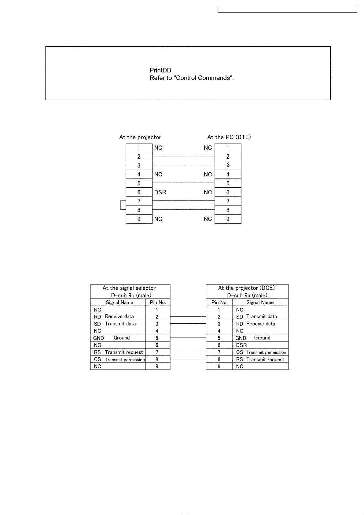
6.5. Communication Cable Specifications
PT-F100NTU / PT-F100NTE / PT-F100NTEA / PT-F100U / PT-F100E / PT-F100EA
6.6. Signal Selector Connecting Cable Specifications
When connecting to a signal selector (ex. TW-SWS62J), use a cable with specifications below.
Connecting method: Connects a video signal cable from the signal selector to "VIDEO IN", and an RGB signal cable to
"COMPUTER 1 IN".
Note:
Set VP control terminal switch of the signal selector to VP TYPE "B".
11
PT-F100NTU / PT-F100NTE / PT-F100NTEA / PT-F100U / PT-F100E / PT-F100EA
7 Disassembly Instructions
Warning:
· Be sure to unplug the power cord from the power outlet before disassembling this projector.
Caution:
· While turning over a printed circuit board, be sure to put a insulating material under it to prevent a short circuit.
· Printed circuit boards and wires must not be pulled forcibly, but be handled carefully.
· Connectors also must be handled carefully.
· When reassembling, replace used adhesive tape with new one (Do not re-use used tape).
· After repairing this projector, be sure to put back the wires and connectors to the original condition.
· Service or repair the product according to service information on the service manual, etc. so that a fire, injury or electric
shock caused by an improper repair may not occur.
1. Do not modify equipments, components and materials when attempting to service or repair.
2. Do not repair nor connect wires even in case of a part of the disconnection when the wiring unit is supplied as a
replacement parts, replace the wiring unit (complete).
3. For a fasten terminal (push-in type terminal), pull out or insert straightly without twisting it.
4. When the fuse has blown, do not turn on the power supply replacing only the fuse because the secondary disaster of
fumes, fire or other hazards is expected. Turn on the power supply after doing the confirmation and measures of
defective causes (structure and circuit, etc.).
5. After the service or the repair is completed, confirm the operation of the product is normal.
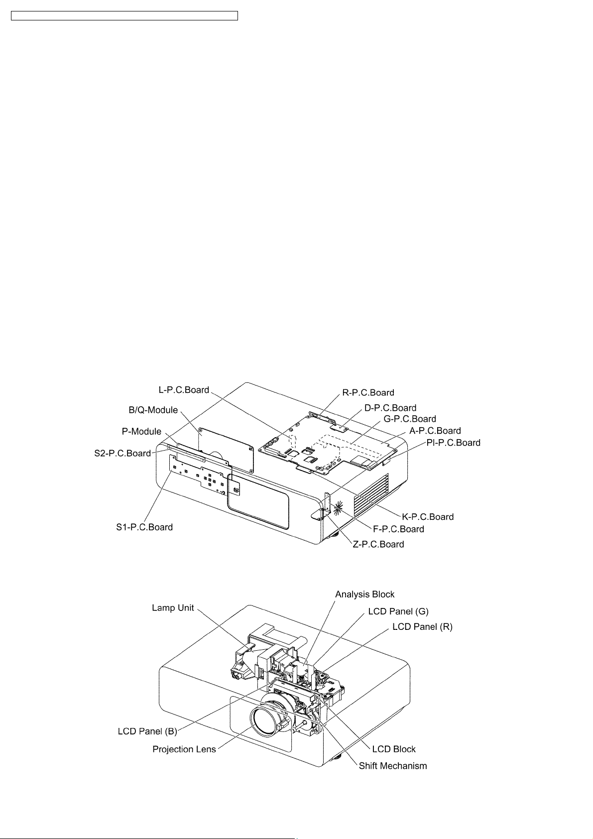
7.1. Printed Circuit Board and Main Parts Location
Electrical Parts
Optical Parts
12
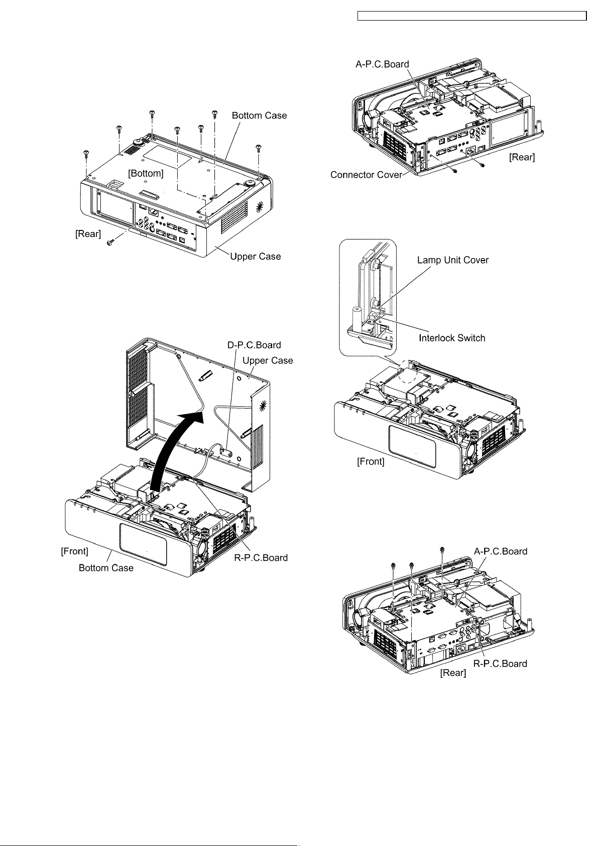
7.2. Removal of Upper Case
1. Turn the projector upside down.
2. Unscrew the 8 screws.
3. Return the projector to the normal position.
4. Lift the upper case upward.
5. Disconnect the flexible cable between D-P.C.Board and RP.C.Board, then remove the upper case.
PT-F100NTU / PT-F100NTE / PT-F100NTEA / PT-F100U / PT-F100E / PT-F100EA
Note:
· When reassembling, confirm the interlock switch is
normal status (the switch is in "ON" position).
7.3. Removal of A-P.C.Board
1. Remove the upper case according to the section 7.2.
"Removal of Upper Case".
2. Unscrew the 2 screws and remove the connector cover.
3. Disconnect all connectors of the cables connected with the
A-P.C.Board.
4. Unscrew the 3 screws and remove the A-P.C.Board block.
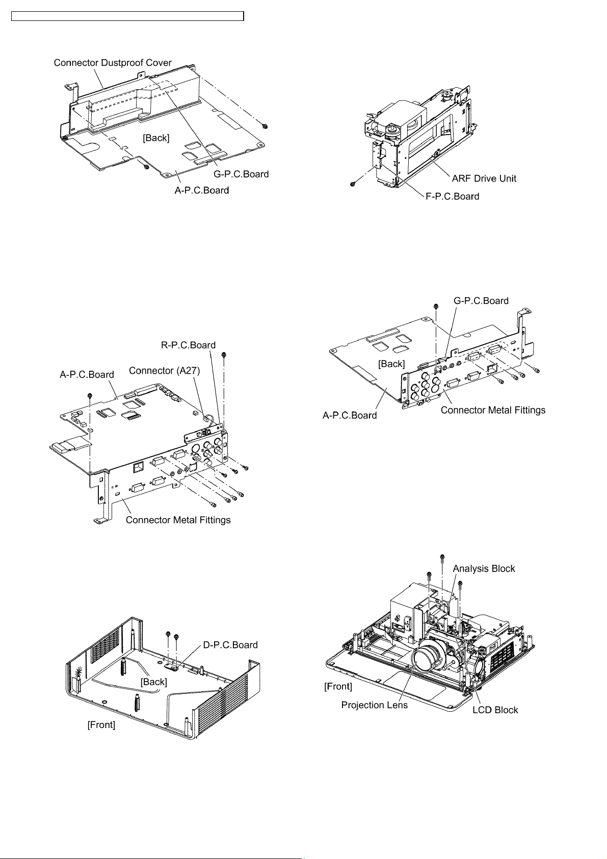
5. Unscrew the 2 screws and remove the connector dustproof
cover.
Note:
· R-P.C.Board is attached on the connector metal
fittings. Be careful with handling.
13
PT-F100NTU / PT-F100NTE / PT-F100NTEA / PT-F100U / PT-F100E / PT-F100EA
6. Disconnect the flexible cable between G-P.C.Board and AP.C.Board (A20).
7. Disconnect the connector between R-P.C.Board and AP.C.Board (A27).
8. Unscrew the 9 screws and remove the connector metal
fittings.
Notes:
· R-P.C.Board and G-P.C.Board are attached on the
connector metal fittings. Be careful with handling.
"Removal of ARF Drive Unit".
2. Unscrew the 1 scre remove the F-P.C.Board
7.6. Removal of G-P.C.Board
1. Remove the A-P.C.Board block according to the steps 1
through 6 in the section 7.3. "Removal of A-P.C.Board".
2. Unscrew the 5 screws and remove the G-P.C.Board.
7.4. Removal of D-P.C.Board
1. Remove the upper case according to the section 7.2.
"Removal of Upper Case".
2. Unscrew the 2 screws and remove the D-P.C.Board.
7.5. Removal of F-P.C.Board
1. Remove the ARF drive unit according to the section 7.27.
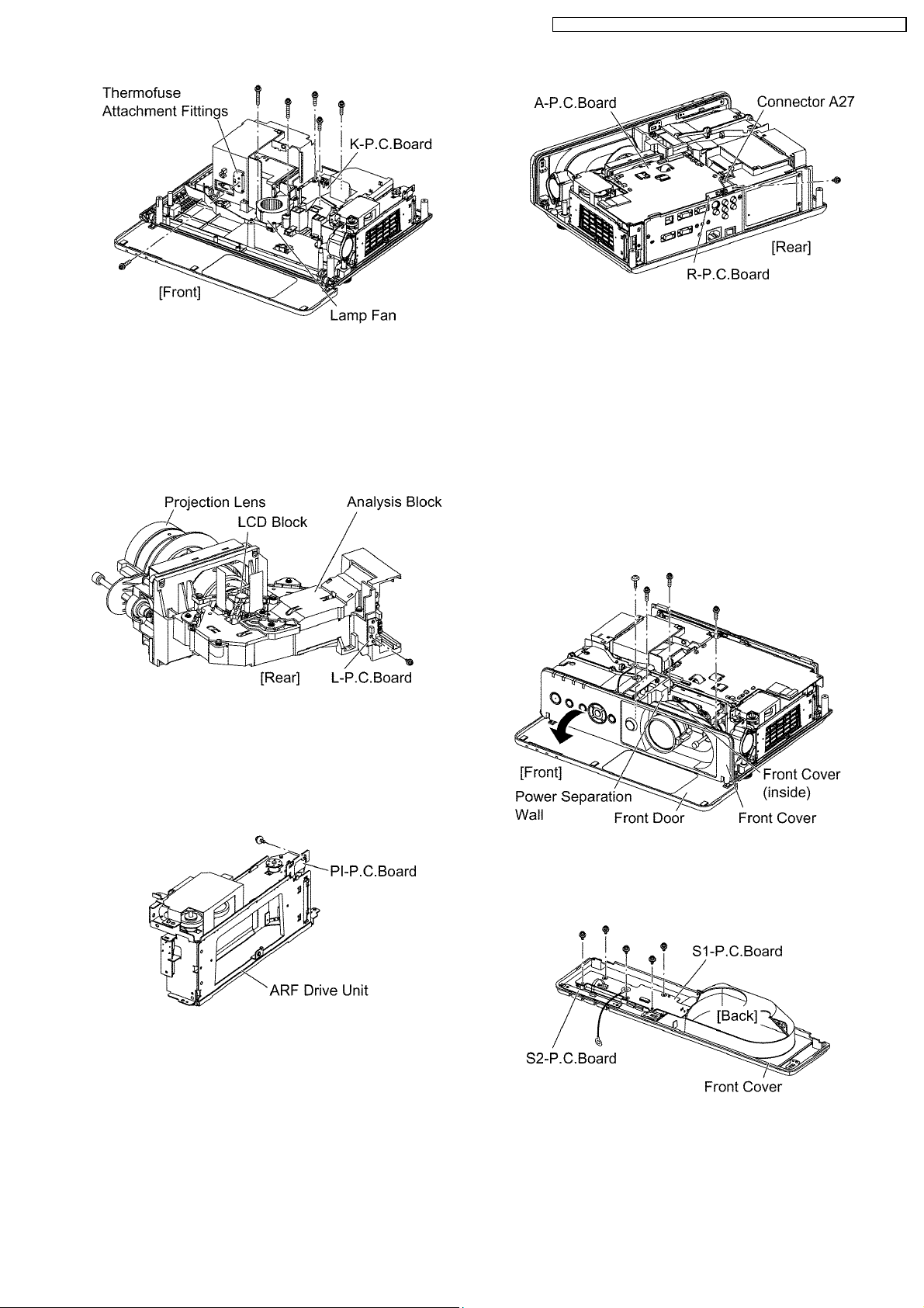
7.7. Removal of K-P.C.Board
1. Remove the lamp unit according to the section 7.16.
"Removal of Lamp Unit".
2. Remove the power block according to the steps 1 through
10 in the section 7.14. "Removal of B/Q Module".
3. Unscrew the 3 screws and remove the block of Analysis
Block, LCD Block and Projection Lens.
4. Unscrew the 2 screws and remove the lamp fan.
5. Unscrew the 1 screw and remove the thermofuse
attachment fittings.
6. Unscrew the 3 screws and remove the K-P.C.Board block.
14
PT-F100NTU / PT-F100NTE / PT-F100NTEA / PT-F100U / PT-F100E / PT-F100EA
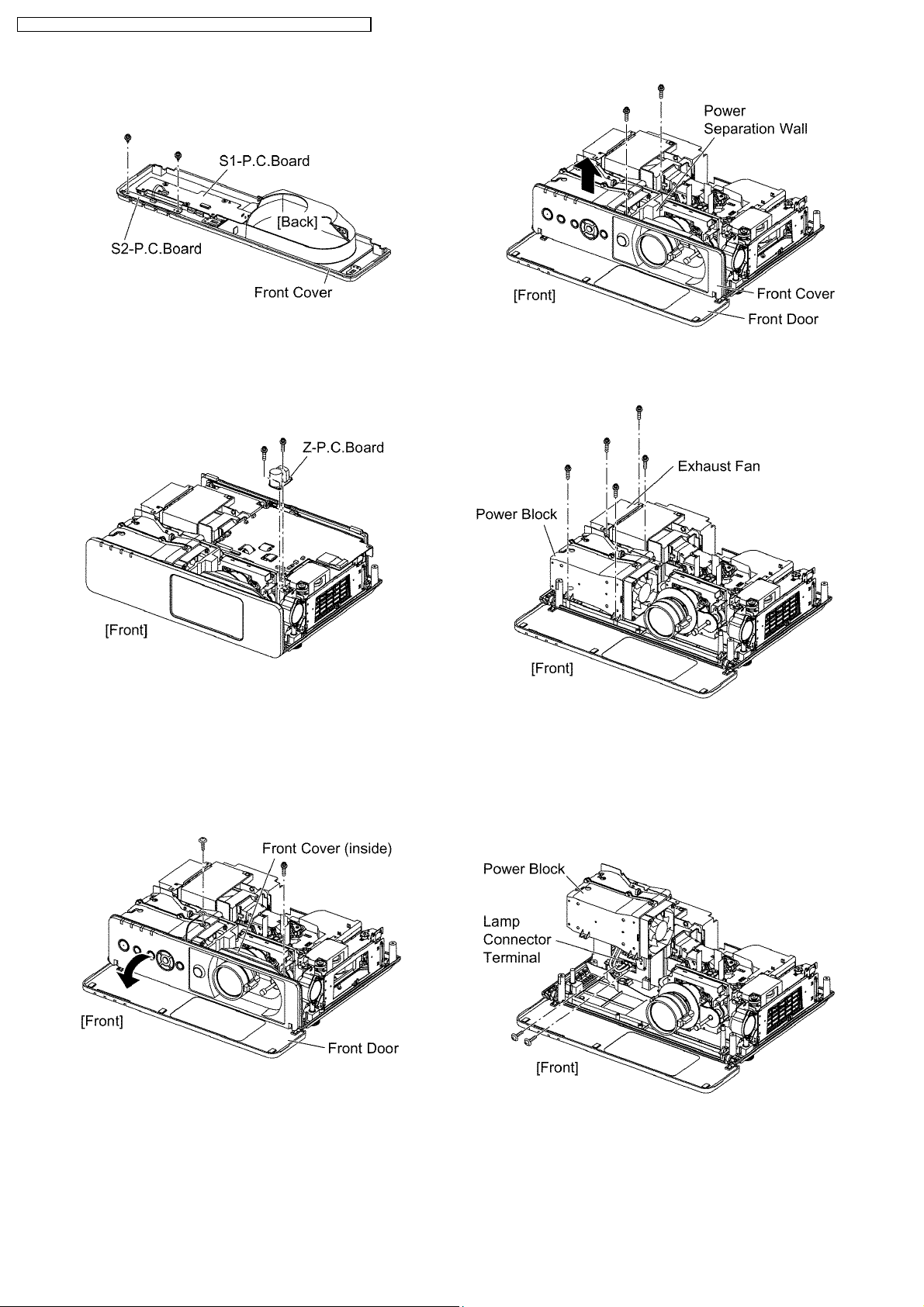
7.11. Removal of S1-P.C.Board
7.8. Removal of L-P.C.Board
1. Remove the block of Analysis Block, LCD Block and
Projection Lens according to the steps 1 through 8 in the
section 7.17. "Removal of Analysis Block and Projection
Lens".
2. Unscrew the 1 screw and remove the L-P.C.Board.
7.9. Removal of PI-P.C.Board
1. Remove the ARF drive unit according to the section 7.27.
"Removal of ARF Drive Unit".
2. Unscrew the 1 screw and remove the PI-P.C.Board.
1. Remove the upper case according to the section 7.2.
"Removal of Upper Case".
2. Open the front door.
3. Unscrew the 1 screw and remove the front cover (inside).
4. Unscrew the 1 screw and remove the grounding terminal.
5. Unscrew the 2 screws and remove the power separation
wall.
6. Remove the front cover.
Note:
· S1-P.C.Board and S2-P.C.Board are attached.
7.10. Removal of R-P.C.Board
1. Remove the upper case according to the section 7.2.
"Removal of Upper Case".
2. Disconnect the connector (S4 or A27) between RP.C.Board and A-P.C.Board.
3. Unscrew the 1 screw and remove the R-P.C.Board.
7. Disconnect the connector between S1-P.C.Board and S2P.C.Board.
8. Unscrew the 5 screws and remove the S1-P.C.Board.
7.12. Removal of S2-P.C.Board
1. Remove the front cover according to the steps 1 through 6
in the section 7.11. "Removal of S1-P.C.Board".
2. Disconnect the connector between S1-P.C.Board and S2-
15
PT-F100NTU / PT-F100NTE / PT-F100NTEA / PT-F100U / PT-F100E / PT-F100EA
P.C.Board.
3. Unscrew the 2 screws and remove the S2-P.C.Board.
7.13. Removal of Z-P.C.Board
1. Remove the upper case according to the section 7.2.
"Removal of Upper Case".
2. Unscrew the 2 screws and remove the Z-P.C.Board.
7. Unscrew the 2 screws and remove the exhaust fan.
8. Unscrew the 3 screws.
7.14. Removal of B/Q-Module
1. Remove the A-P.C.Board block according to the steps 1
through 4 in the section 7.3. "Removal of A-P.C.Board".
2. Open the front door.
3. Unscrew the 1 screw and remove the front cover (inside).
4. Unscrew the 1 screw and release the grounding terminal.
5. Unscrew the 2 screws and remove the power separation
wall.
6. Remove the front cover.
9. Lift the power block and unscrew the 2 screws, then
disconnect the lamp connector terminal.
Note:
· Because the lead wire between the power block and
the lamp connector terminal is short, be careful not
to apply excessive force into it.
10. Remove the power block.
11. Unscrew the 5 screws and separate the power unit and the
ballast unit.
16
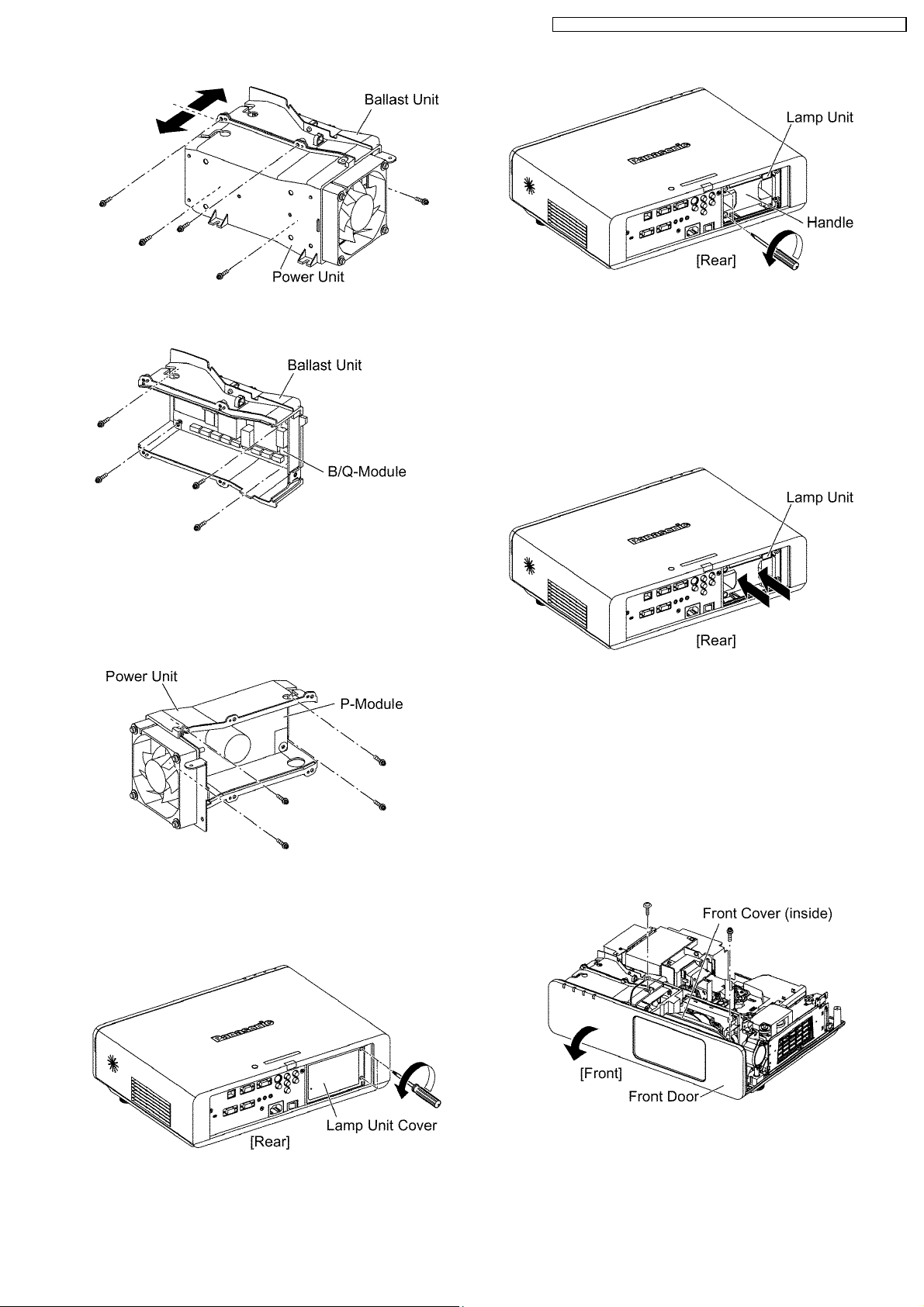
12. Unscrew the 4 screws and remove the B/Q-Module.
PT-F100NTU / PT-F100NTE / PT-F100NTEA / PT-F100U / PT-F100E / PT-F100EA
Note:
· When installing the lamp unit in the main unit, place
it in a specified position and press the right and left
sides of the lamp unit (arrow positions shown in the
figure below), and confirm the lamp unit is inserted
securely.
Then, tighten the 2 screws fixing the lamp unit, and
attach the lamp unit cover.
7.15. Removal of P-Module
1. Remove the power unit according to the steps 1 through 11
in the section 7.14. "Removal of B/Q Module".
2. Unscrew the 4 screws and remove the P-Module.
7.16. Removal of Lamp Unit
1. Loosen the 2 screws until they idle, remove the lamp unit
cover.
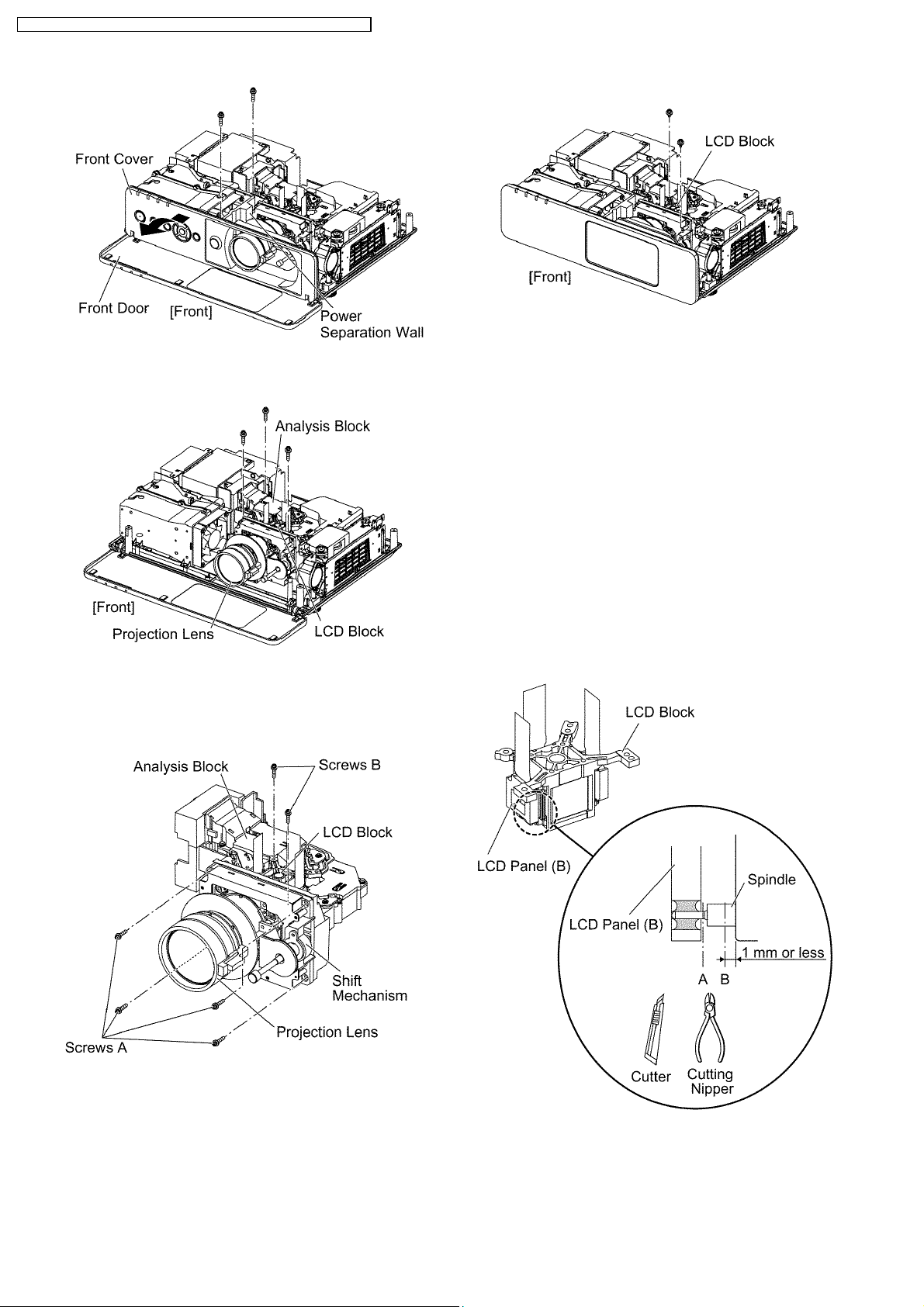
7.17. Removal of Analysis Block
and Projection Lens
1. Remove the lamp unit according to the section 7.16.
"Removal of Lamp Unit".
2. Remove the A-P.C.Board block according to the steps 1
through 4 in the section 7.3. "Removal of A-P.C.Board".
3. Open the front door.
4. Unscrew the 1 screw and remove the front cover (inside).
5. Unscrew the 1 screw and remove the grounding terminal.
2. Loosen the 2 screws until they idle, remove the lamp unit
with the handle.
6. Unscrew the 2 screws and remove the power separation
wall.
7. Remove the front cover.
17
PT-F100NTU / PT-F100NTE / PT-F100NTEA / PT-F100U / PT-F100E / PT-F100EA
8. Unscrew the 3 screws and remove the block of Analysis
Block, LCD Block and Projection Lens.
9. Unscrew the 4 screws A and remove the projection lens
with the shift mechanism.
10. Unscrew the 2 screws B and remove the LCD block (the
analysis block remains).
panel.
7.19. Replacement of LCD Panel (B)
1. Remove the LCD block according to the section 7.18.
"Removal of LCD Block".
Note:
· Be careful not to touch the surface of prism and LCD
panel.
2. Cut the 4 LCD panel installation spindles at the position A
and remove the LCD panel.
3. Cut the 4 LCD panel installation spindles at the position B
and remove them.
Notes:
· Work carefully not to apply external force around the
spindle part by using a cutter, cutting nipper or the
like for cutting the spindle.
· Adjust the height after the spindle is cut to 1 mm or
less.
7.18. Removal of LCD Block
1. Remove the A-P.C.Board block according to the steps 1
through 4 in the section 7.3. "Removal of A-P.C.Board".
2. Unscrew the 2 screws and remove the LCD block.
Note:
· Be careful not to touch the surface of prism and LCD
4. Attach the base plate with 4 screws.
5. Tighten the 2 screws temporarily just until new LCD panel
(with the panel attachment and panel adjuster) can be
18
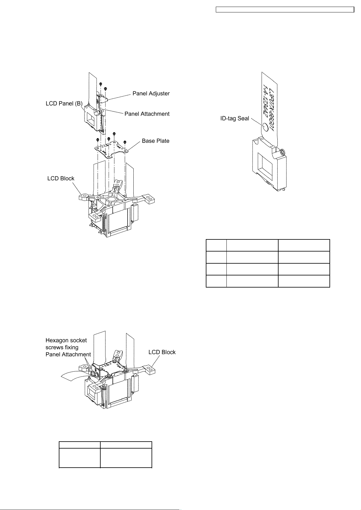
shifted by your fingers.
Note:
· The panel adjustment fittings set (panel attachment,
panel adjuster and base plate) is an option for
service.
PT-F100NTU / PT-F100NTE / PT-F100NTEA / PT-F100U / PT-F100E / PT-F100EA
· Since the ID-tag seal is pasted to the FPC of LCD Panel,
(R), (G) or (B) can be easily identified by the color of the
seal.
· Finally, identify the panel color by the part number printed
on the FPC.
6. Reassemble the projector in the reverse order of
disassembling, but leave the upper case and the screws
fixing the A-P.C.Board block as they are removed.
7. Adjust the convergence according to the section 8.4.
"Convergence Adjustment".
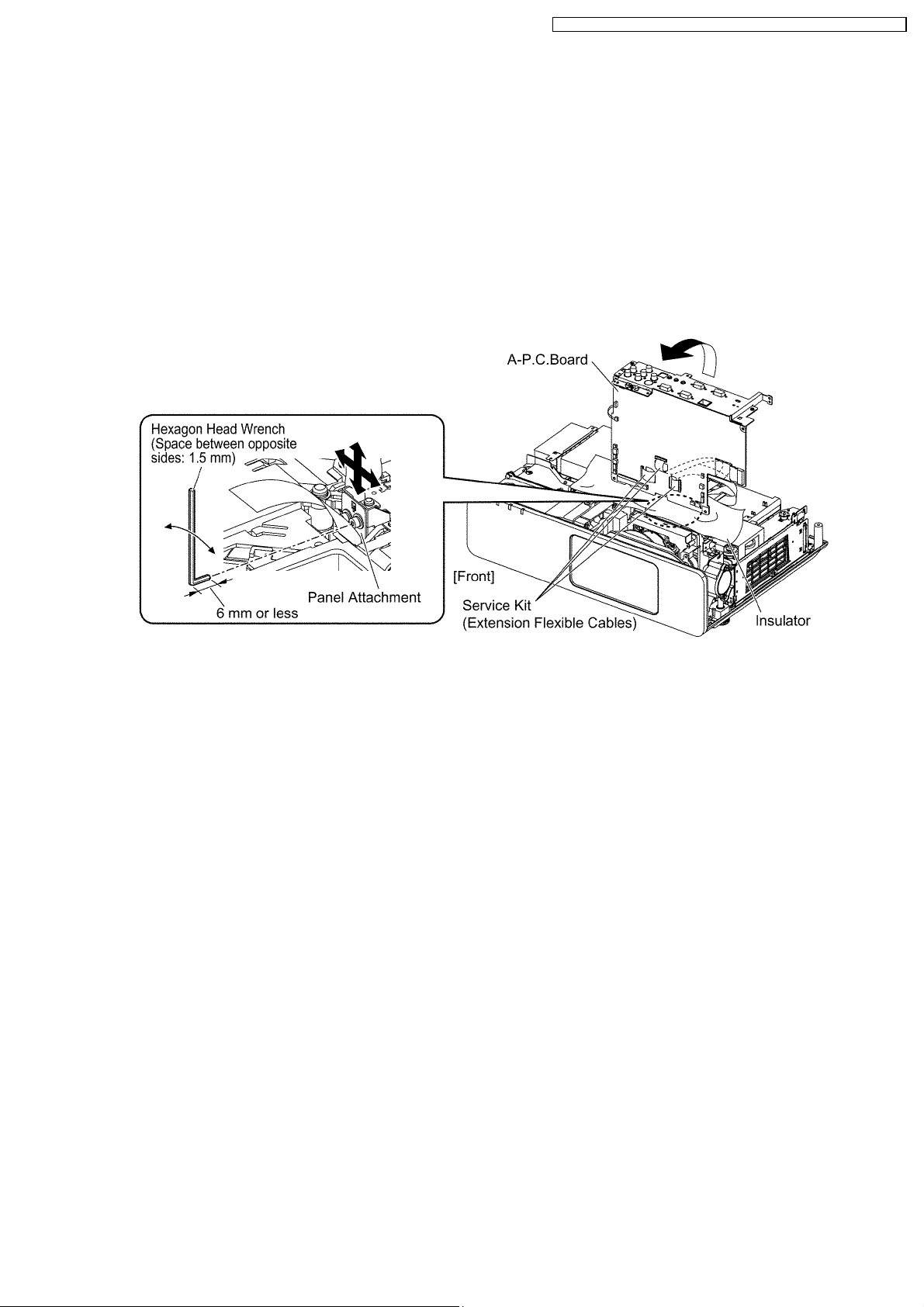
8. After the adjustment, while paying attention not to vary the
adjusting result, tighten the 2 screws fixing the panel
attachment with a hexagon head wrench.
Notes:
· Prepare a hexagon head wrench processed short.
9. Reassemble the projector as it was.
7.21. LCD Panel Combination
· Part number is printed on the FPC of LCD Panel.
· When replacing LCD Panel, use a component which has
the same part number as the original.
LCD
panel
R L5BDAYY00068
G L5BDAYY00072
B L5BDAYY00070
Combination1 Combination2
(L3P07X-65G01)
(L3P07X-66G01)
(L3P07X-65G01)
L5BDAYY00071
(L3P07X-66G01)
L5BDAYY00069
(L3P07X-65G01)
L5BDAYY00073
(L3P07X-66G01)
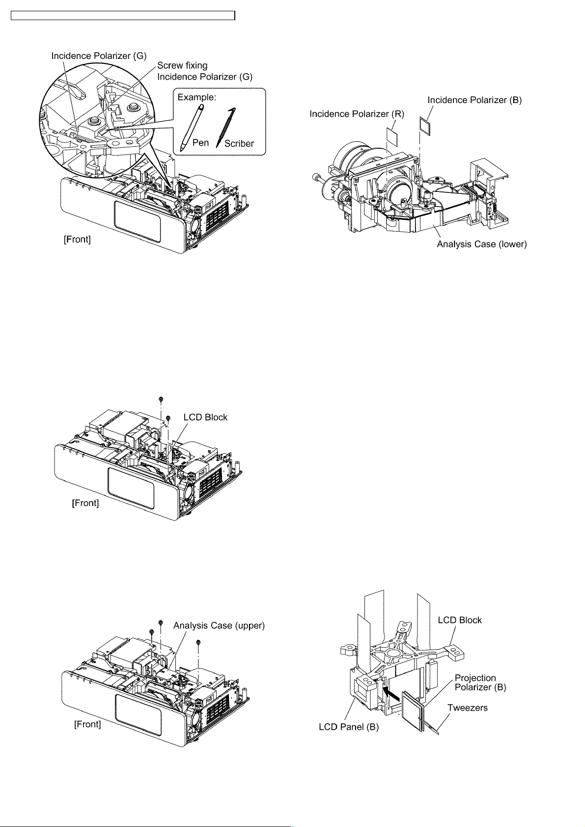
7.22. Replacement of Incidence
Polarizer (G)
1. Remove the A-P.C.Board block according to the steps 1
through 4 in the section 7.3. "Removal of A-P.C.Board".
2. Mark positions of the incidence polarizer (G).
Note:
· Mark accurately as possible because the marks will
be used for resetting the incidence polarizer
position.
3. Unscrew the 1 screw and remove the incidence polarizer
(G).
4. Attach a new incidence polarizer (G) and align it with the
mark.
5. Tighten the 1 screw with care not to move the incidence
polarizer position.
7.20. LCD Panel Discrimination
ID-tag seal color LCD panel
Red LCD panel (R)
Blue LCD panel (B)
(No seal) LCD panel (G)
19
PT-F100NTU / PT-F100NTE / PT-F100NTEA / PT-F100U / PT-F100E / PT-F100EA
Note:
· Be careful not to touch the surface of incidence
polarizer.
7.23. Replacement of Incidence
Polarizer (R and B)
1. Remove the A-P.C.Board block according to the steps 1
through 4 in the section 7.3. "Removal of A-P.C.Board".
2. Unscrew the 2 screws and remove the LCD block.
Note:
· Be careful not to touch the surface of prism and LCD
panel.
3. Unscrew the 3 screws and remove the analysis case
(upper) .
Note:
· The incidence polarizer (G) is installed in the
analysis case (upper). Handle with care not to apply
external force to the incidence polarizer (G).
7.24. Replacement of Projection
Polarizer
· The procedure is described as an example of projection
polarizer (B).
1. Remove the LCD block according to the section 7.18.
"Removal of LCD Block".
2. Remove the projection polarizer which requires replacing.
(The projection polarizer is secured with adhesive tape.)
Notes:
· Be careful not to damage peripheral components
(prism, LCD panel, etc.).
· Use tweezers.
3. Install new projection polarizer.
a. Put adhesive tape on the projection polarizer.
b. Stick the projection polarizer on the specified position.
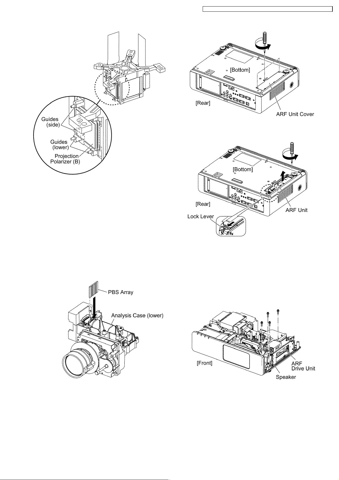
Notes:
· Align the projection polarizer with the guides
(lower, side) of LCD block.
· Be careful not to touch the surface of projection
polarizer.
· Use tweezers.
c. Press the adhesive part and secure the projection
polarizer.
4. Replace the incidence polarizer.
20
PT-F100NTU / PT-F100NTE / PT-F100NTEA / PT-F100U / PT-F100E / PT-F100EA
3. Loosen the 1 screw until it idles, remove the ARF unit while
sliding the lock lever.
7.25. Replacement of PBS Array
(Analysis Block)
1. Remove the analysis case (upper) according to the steps 1
through 3 in the section 7.23. "Replacement of Incidence
Polarizer (R and B)".
2. Remove the PBS array.
3. Install new PBS array.
Note:
· Be careful not to mistake the direction (inside and
outside, upper and lower).
· Be careful not to touch the surface of PBS array.
7.27. Removal of ARF Drive Unit
1. Remove the ARF unit according to the section 7.26.
"Removal of ARF (Auto Rolling Filter) Unit".
2. Remove the A-P.C.Board block according to the steps 1
through 4 in the section 7.3. "Removal of A-P.C.Board".
3. Unscrew the 2 screws and remove the speaker block.
4. Unscrew the 1 screw and remove the ARF drive unit.
7.26. Removal of ARF (Auto Rolling
Filter) Unit
1. Turn the projector upside down.
2. Loosen the 3 screws until they idle, remove the ARF unit
cover.
21
PT-F100NTU / PT-F100NTE / PT-F100NTEA / PT-F100U / PT-F100E / PT-F100EA
8 Measurement and Adjustments
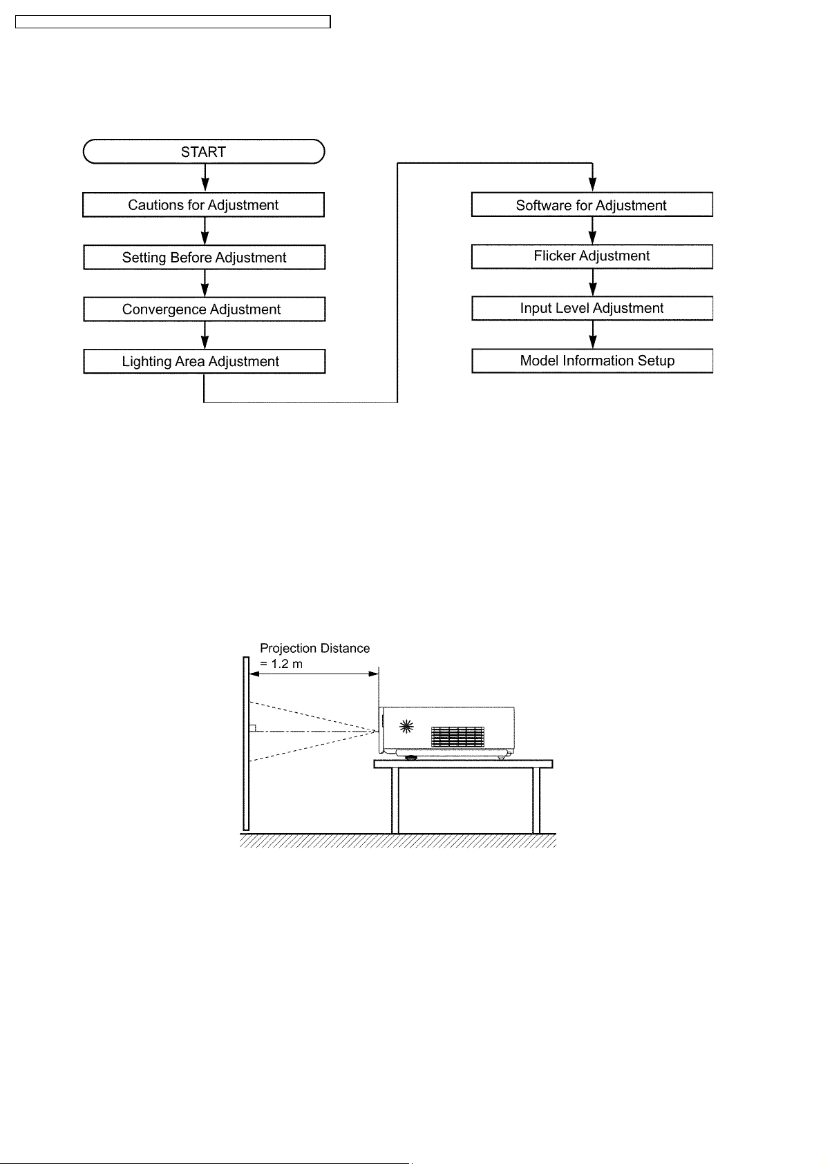
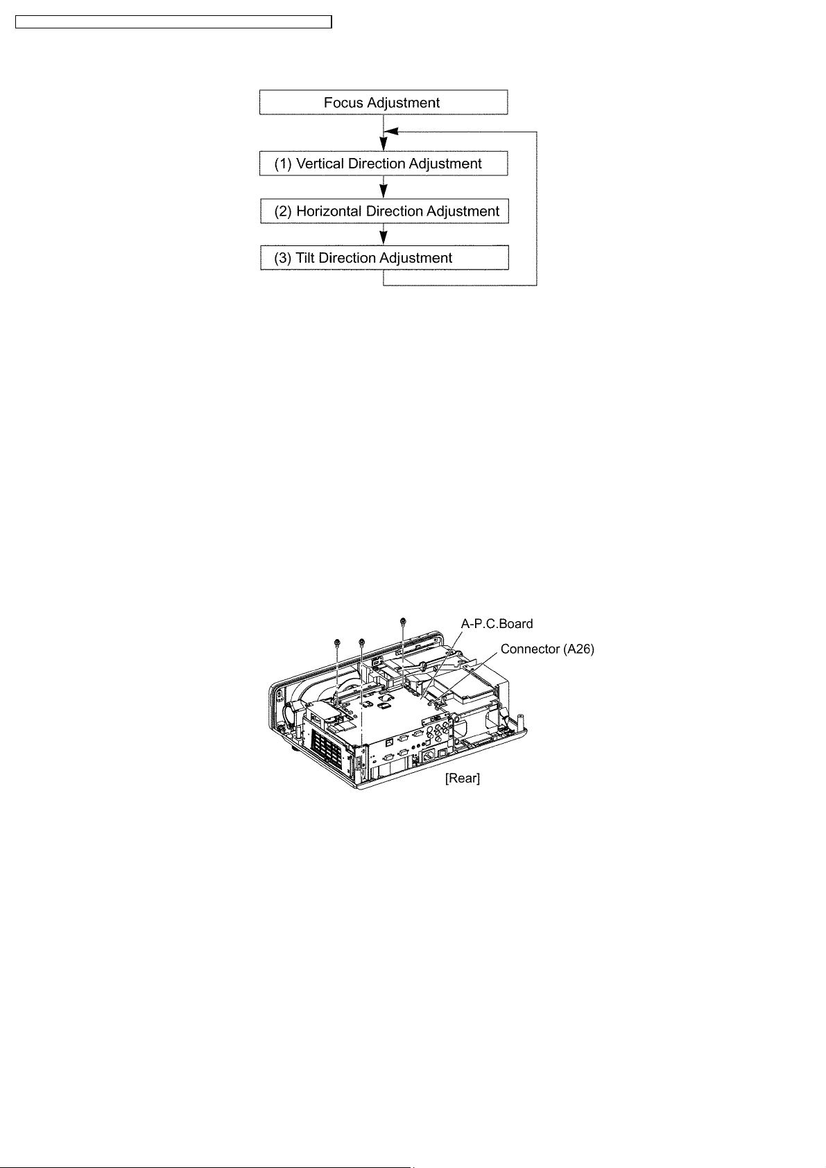
8.1. Adjustment Procedure Flowchart
8.2. Cautions for Adjustment
· Never unplug the power cord until the power indicator on the projector illuminates red.
· To maintain and ensure safety, always use the designated components for replacement parts.
· If removing any clamps, lead wires or connectors, always place them back in their proper locations.
· Be careful not to damage the lead wires or components when using a soldering iron or similar tool.
8.3. Setting Before Adjustment
· Set up the projector to obtain the projection distance below.
· Turn the zoom ring of the projector to obtain the largest size of the picture.
8.4. Convergence Adjustment
Execute this adjustment when replacing the LCD panel (B) .
8.4.1. Tools to be used
Service Kit : This kit is composed of 3 extension flexible cables.
Note:
· Consult your dealer or Authorized Service Center for the service kit.
8.4.2. Preparation
1. Loosen 2 screws fixing the panel adjuster and 2 screws fixing the panel attachment, then tighten the 4 screws temporarily just
until the LCD panel can be shifted by your fingers.
22
PT-F100NTU / PT-F100NTE / PT-F100NTEA / PT-F100U / PT-F100E / PT-F100EA
Note:
· See figures in the section 7.19. "Replacement of LCD Panel (B)" for 2 screws fixing the panel adjuster and 2 screws
fixing the panel attachment.
2. Reassemble the projector in the reverse order of disassembling, but leave the upper case and the screws fixing the AP.C.Board block as they are removed.
3. Disconnect the connector between L-P.C.Board and A-P.C.Board (A26).
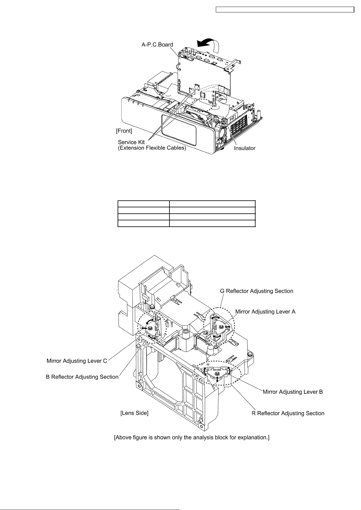
4. Connect the service kit (extension flexible cables).
· Each flexible cable of LCD Panels (R/G/B) - Connectors (A1/A2/A3) on A-P.C.Board
5. Covering with an insulator (cloth or the like) to prevent a short circuit, set the A-P.C.Board block on the main unit.
Note:
· Handle with care not to apply external force to connecting parts which connect the main unit and A-P.C.Board.
8.4.3. Adjustment Procedure
Prepare 2 pieces of thick black paper (23 mm × 100 mm) that can be shaded.
· Cover and shade LCD panels (R) and (G) with the paper.
1. Display the green crosshatch pattern and adjust the lens focus.
2. Display green and blue crosshatch patterns.
3. Adjust focus by shifting the panel adjuster for LCD panel (B) back and forth, then tighten the 2 screws.
4. Adjust the LCD panel (B) position so that the vertical center of blue crosshatch pattern is overlapped with the vertical center of
green crosshatch pattern.
5. Adjust the LCD panel (B) position so that the horizontal center of blue crosshatch pattern is overlapped with the horizontal
center of green crosshatch pattern.
6. Correct the tilt of the blue crosshatch pattern by adjusting the LCD panel (B) position.
7. Display green, red and blue crosshatch patterns and confirm the convergence. If it is necessary, fine adjust the convergence
so that the blue crosshatch pattern is overlapped with green one.
23
PT-F100NTU / PT-F100NTE / PT-F100NTEA / PT-F100U / PT-F100E / PT-F100EA
Repeat steps (1) to (3) until the green and blue crosshatch
patterns merge into a cyan pattern.
8. After the adjustment, reassemble the projector according to the steps 8 through 9 in the section 7.19. "Replacement of LCD
Panel (B)".
8.5. Lighting Area Adjustment
8.5.1. Tools to be used
Service Kit: This kit is composed of 3 extension flexible cables.
Note:
· Consult your dealer or Authorized Service Center for the service kit.
8.5.2. Preparation
1. Remove the upper case and the connector cover according to the steps 1 and 2 in the section 7.3. "Removal of A-P.C.Board".
2. Unscrew the 3 screws.
3. Disconnect the connector between L-P.C.Board and A-P.C.Board (A26).
4. Connect the service kit (extension flexible cables).
· Each flexible cable of LCD Panels (R/G/B) - Connectors (A1/A2/A3) on A-P.C.Board
5. Covering with an insulator (cloth or the like) to prevent a short circuit, set the A-P.C.Board block on the main unit.
Note:
· Handle with care not to apply external force to connecting parts which connect the main unit and A-P.C.Board.
24
8.5.3. Adjustment Procedure
8.5.3.1. Outline
PT-F100NTU / PT-F100NTE / PT-F100NTEA / PT-F100U / PT-F100E / PT-F100EA
When the lighting area is off from the adjustment and color unevenness appears, adjust the lighting area into correct position.
Symptom Measure
Magenta unevenness G Reflector Adjustment
Cyan unevenness R Reflector Adjustment
Yellow unevenness B Reflector Adjustment
· Shifting the mirror adjusting lever horizontally, adjust color unevenness on the screen upper/lower sides.
· Twisting the mirror adjusting lever, adjust color unevenness on the screen right/left sides.
8.5.3.2. G Reflector Adjustment
1. Turn on the power and display 100 % white pattern on the screen.
2. Loosen the 1 screw fixing the mirror adjusting lever A just until the lever can be shifted.
25
PT-F100NTU / PT-F100NTE / PT-F100NTEA / PT-F100U / PT-F100E / PT-F100EA
3. Adjust the mirror adjusting lever A position to minimize color unevenness on the screen by shifting the lever in arrow directions.
4. Tighten the 1 screw.
8.5.3.3. R Reflector Adjustment
1. Turn on the power and display 100 % white pattern on the screen.
2. Loosen the 1 screw fixing the mirror adjusting lever B just until the lever can be shifted.
3. Adjust the mirror adjusting lever B position to minimize color unevenness on the screen by shifting the lever in arrow directions.
4. Tighten the 1 screw.
8.5.3.4. B Reflector Adjustment
1. Turn on the power and display 100 % white pattern on the screen.
2. Loosen the 1 screw fixing the mirror adjusting lever C just until the lever can be shifted.
3. Adjust the mirror adjusting lever C position to minimize color unevenness on the screen by shifting the lever in arrow directions.
4. Tighten the 1 screw.
8.6. Software for Adjustment
8.6.1. Outline
· This projector needs computer-aided adjustments.
· After the software adjustments, this projector must be turned off and on again to memorize the settings.
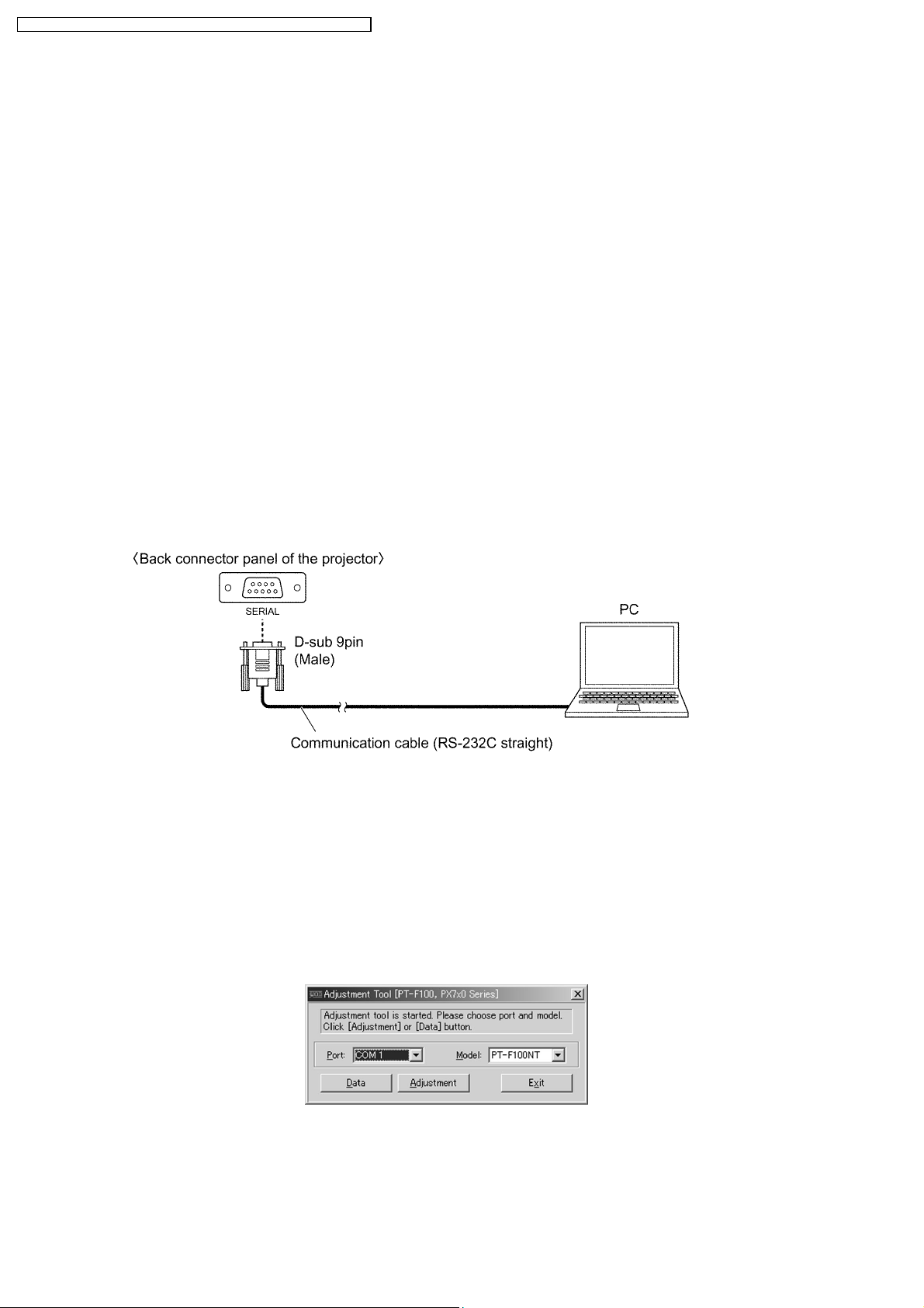
· Connect the cable between the projector and a PC as shown below.
· Updating the software will change the version number.
8.6.2. Operating Procedure
1. Run software program by the keyboard entry.
Note:
· Use the software program as below.
Adjustment Tool [PT-F100, PX7x0 Series]
2. The first menu is Port and Model selection menu.
3. Adjust the projector by selecting the necessary item from the menu in each stage.
8.6.3. Port and Model Selection Menu
Select the applying item with the list box and click "Data" or "Adjustment".
8.6.3.1. Explanation of Buttons
Port:
Port name of PC which connects with the projector
26
Model:
Model name of projectors
Data:
Displays the data transmission/reception menu.
Adjustment:
Displays the adjustment menu.
Exit:
Exits this application.
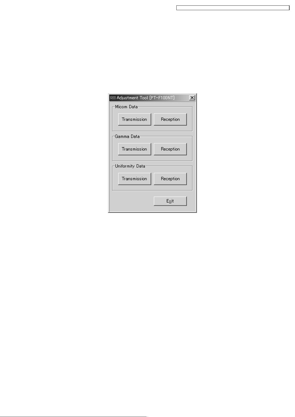
8.6.4. Data Transmission/Reception Menu
PT-F100NTU / PT-F100NTE / PT-F100NTEA / PT-F100U / PT-F100E / PT-F100EA
8.6.4.1. Explanation of Buttons
Micom Data Transmission:
Reads the microcomputer data from the file and transmits it to the projector.
Micom Data Reception:
Receives the microcomputer data from the projector and writes it in the file.
Gamma Data Transmission:
Reads the gamma data from the file and transmits it to the projector.
Gamma Data Reception:
Receives the gamma data from the projector and writes it in the file.
Uniformity Data Transmission:
Reads the color unevenness correction data from the file and transmits it to the projector.
Uniformity Data Reception:
Receives the color unevenness correction data from the projector and writes it in the file.
Exit:
Exits this application.
8.6.4.2. Receiving and transmitting of the data
Click a target button and specify a file name.
27
PT-F100NTU / PT-F100NTE / PT-F100NTEA / PT-F100U / PT-F100E / PT-F100EA
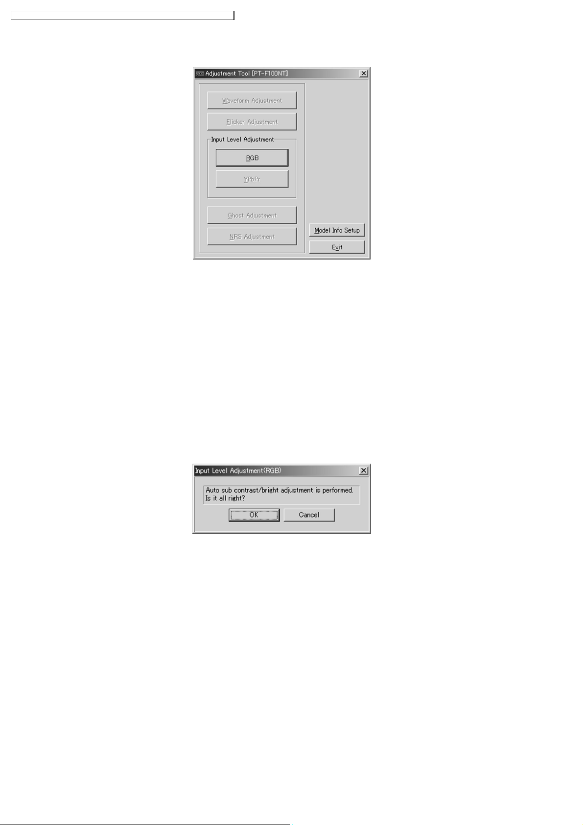
8.6.5. Adjustment Menu
8.6.5.1. Explanation of Buttons
Input Level Adjustment RGB:
Displays the RGB input level adjustment menu.
Model Info Setup
Displays the model information setup menu.
Exit:
Exits this application.
8.7. Flicker Adjustment
According to the procedure of chapter 5 "Flicker Adjustment Mode", minimize the flicker.
8.8. Input Level Adjustment
8.8.1. Adjustment Menu
8.8.2. Explanation of Buttons
OK:
Executes automatic sub contrast and sub brightness adjustments, then closes this dialog.
Cancel:
Cancels this menu.
8.8.3. Equipment to be used
PC, RGB Signal Generator, Software for Adjustment
8.8.4. Adjustment Procedure
1. Display Input Level Adjustment(RGB) menu.
2. Input a window pattern signal to COMPUTER 1 IN connector.
Note:
· Use approx. 15 % window pattern as follows.
Black background (screen width) : White window width = 2 : 1
Black background (screen height) : White window height = 3 : 1
28

· Use the window pattern of XGA (1 024 × 768).
3. Click the OK button.
8.9. Model Information Setup
8.9.1. Adjustment Menu
8.9.2. Explanation of Buttons
OK:
Executes model information setup, then closes this dialog.
Cancel:
Cancels this menu.
PT-F100NTU / PT-F100NTE / PT-F100NTEA / PT-F100U / PT-F100E / PT-F100EA
8.9.3. Equipment to be used
PC, Software for Adjustment
8.9.4. Setup Procedure
Set the projector into standby mode (POWER button on the projector control panel illuminated red), and execute the following
procedure.
1. Display Model Information Setup menu.
2. Click the OK button.
29
PT-F100NTU / PT-F100NTE / PT-F100NTEA / PT-F100U / PT-F100E / PT-F100EA
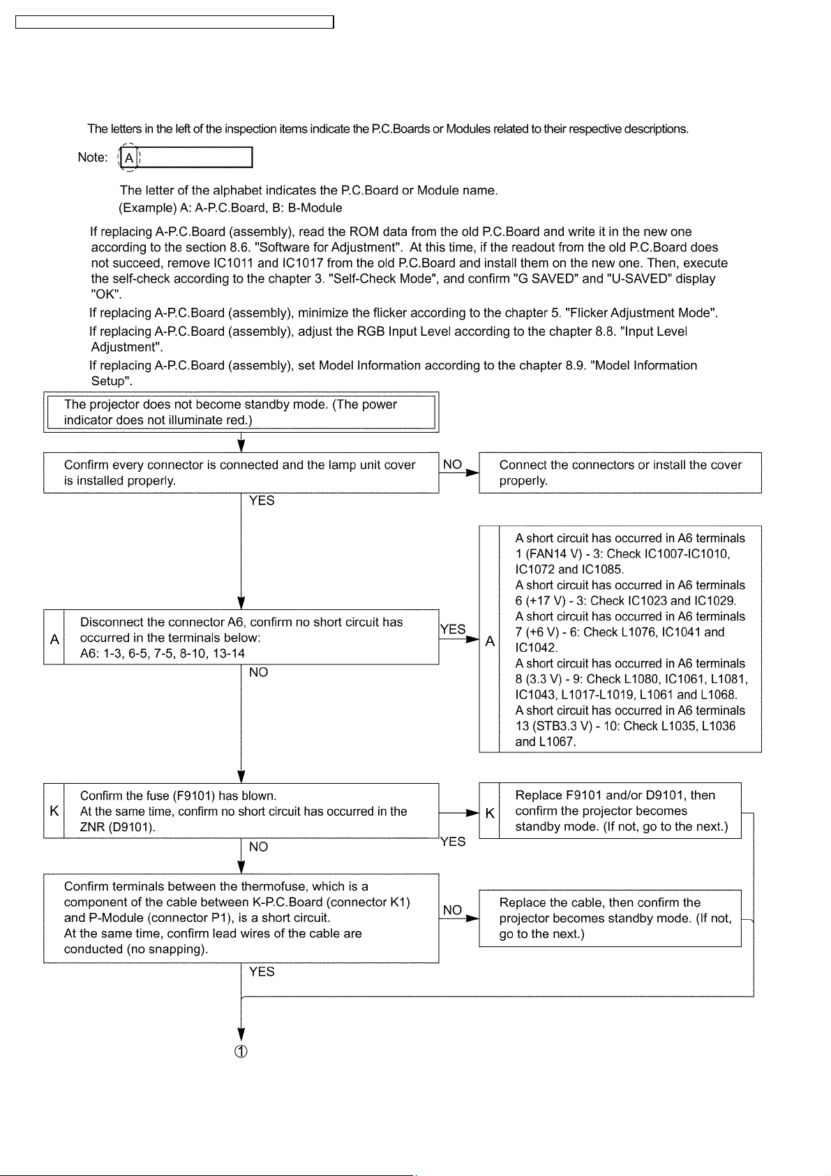
9 Troubleshooting
30
 Loading...