

Panasonic PT-DW800E User Manual
Operating Instructions
Functional Manual
DLPTM Projector
Model No.
PT-DW730E
Commercial Use
PT-DW730EL
PT-DX800E
PT-DX800EL
Thank you for purchasing this Panasonic product.
■ This manual is common to all the models regardless of suffixes of the Model No.
zS: Silver model, the standard zoom lens supplied LS: Silver model, the lens sold separately
K: Black model, the standard zoom lens supplied LK: Black model, the lens sold separately
■ Before operating this product, please read the instructions carefully and save this manual
for future use.
■ Before using your projector, be sure to read “Read this first!” (
W0711SM0 -YI
pages 2 to 8)
ENGLISH
TQBJ0380

Information
Read this rst!
Read this rst!
Information
Important
WARNING: THIS APPARATUS MUST BE EARTHED.
WARNING:
Machine Noise Information Ordinance 3. GSGV, January 18, 1991: The sound pressure level at the operator
position is equal or less than 70 dB (A) according to ISO 7779.
WARNING:
1. Remove the plug from the mains socket when this unit is not in use for a prolonged period of time.
2. Topreventelectricshock,donotremovecover.Nouserserviceablepartsinside.Referservicingtoqualied
3. Do not remove the earthing pin on the mains plug. This apparatus is equipped with a three prong
WARNING:
CAUTION: To assure continued compliance, follow the attached installation instructions, which include using
Topreventdamagewhichmayresultinreorshockhazard,donotexposethisappliancetorain
or moisture.
service personnel.
earthingtypemainsplug.Thisplugwillonlytanearthing-typemainssocket.Thisisasafetyfeature.Ifyou
are unable to insert the plug into the mains socket, contact an electrician. Do not defeat the purpose of the
earthing plug.
This is a class A product. In a domestic environment this product may cause radio interference in which case
the user may be required to take adequate measures.
the provided power cord and shielded interface cables when connecting to computer or peripheral
device. If you use serial port to connect PC for external control of projector, you must use optional
RS-232Cserialinterfacecablewithferritecore.Anyunauthorizedchangesormodicationsto
this equipment will void the user’s authority to operate.
EEE Yönetmeliğine Uygundur.
EEE Complies with Directive of Turkey.
2 - ENGLISH
Read this rst!
13A250V
BS1363/A
HE-8
N
ASA
L
IMPORTANT: THE MOULDED PLUG (U.K. only)
FOR YOUR SAFETY, PLEASE READ THE FOLLOWING TEXT CAREFULLY.
This appliance is supplied with a moulded three pin mains plug for your safety and convenience. A 13 amp fuse
is tted in this plug. Should the fuse need to be replaced, please ensure that the replacement fuse has a rating
of 13 amps and that it is approved by ASTA or BSI to BS1362.
Important
Information
Check for the ASTA mark
or the BSI mark on the body of the fuse.
If the plug contains a removable fuse cover, you must ensure that it is retted when the fuse is replaced. If you
lose the fuse cover, the plug must not be used until a replacement cover is obtained. A replacement fuse cover
can be purchased from an Authorised Service Center.
If the tted moulded plug is unsuitable for the mains socket in your home, then the fuse should be
removed and the plug cut off and disposed of safely.
There is a danger of severe electrical shock if the
cut off plug is inserted into any 13 amp socket.
If a new plug is to be tted, please observe the wiring code as shown below.
If in any doubt, please consult a qualied electrician.
WARNING:
IMPORTANT:
THIS APPLIANCE MUST BE EARTHED.
The wires in this mains lead are coloured in accordance with the following code:
Green - and - Yellow: Earth
Blue: Neutral
Brown: Live
As the colours of the wire in the mains lead of this appliance may not correspond with the coloured markings
dentifying the terminals in your plug, proceed as follows.
i
The wire which is coloured GREEN - AND - YELLOW must be connected to the terminal in the
plug which is marked with the letter E or by the Earth symbol
or coloured GREEN or GREEN -
AND - YELLOW.
The wire which is coloured BLUE must be connected to the terminal in the plug which is marked
with the letter N or coloured BLACK.
The wire which is coloured BROWN must be connected to the terminal in the plug which is
marked with the letter L or coloured RED.
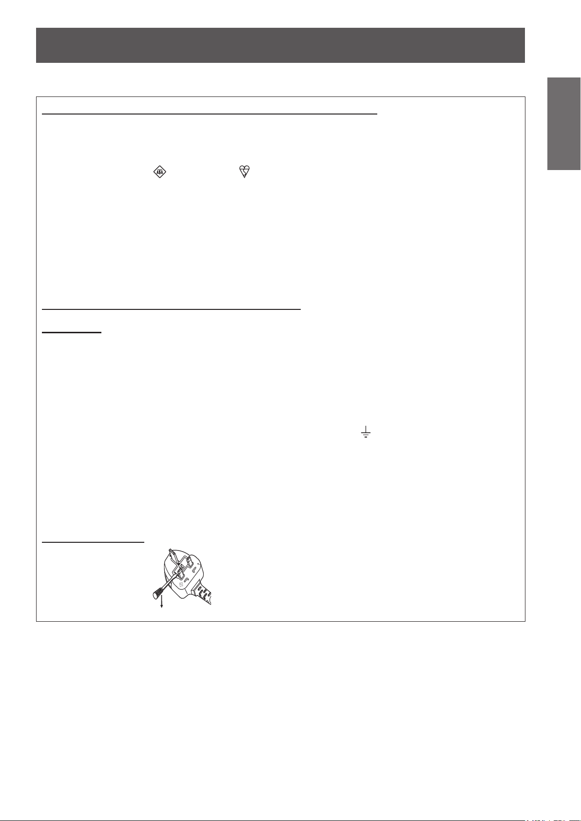
How to replace the fuse: Open the fuse compartment with a screwdriver and replace the fuse.
ENGLISH - 3

Read this rst!
Information
Important
WARNING:
The wall outlet or the circuit breaker shall be installed near the equipment and shall be easily
accessible when problems occur. If the following problems occur, cut off the power supply
immediately.
Continueduseoftheprojectorintheseconditionswillresultinreorelectricshock.
During a thunderstorm, do not touch the projector or the cable.
Electric shocks can result.
Do not do anything that might damage the power cord or the power plug.
Ifthepowercordisusedwhiledamaged,electricshocks,short-circuitsorrewillresult.
Completely insert the power plug into the wall outlet and the power connector into the projector terminal.
If the plug is not inserted correctly, electric shocks or overheating will result.
Do not use anything other than the provided power cord.
Failure to observe this will result in electric shocks.
Clean the power plug regularly to prevent it from becoming covered in dust.
Failuretoobservethiswillcauseare.
Do not handle the power plug with wet hands.
Failure to observe this will result in electric shocks.
Do not overload the wall outlet.
Ifthepowersupplyisoverloaded(ex.,byusingtoomanyadapters),overheatingmayoccurandrewillresult.
POWER
zIf foreign objects or water get inside the projector, cut off the power supply.
zIf the projector is dropped or the cabinet is broken, cut off the power supply.
zIf you notice smoke, strange smells or noise coming from the projector, cut off the power supply.
Please contact an Authorized Service Center for repairs, and do not attempt to repair the projector yourself.
zDonotdamagethepowercord,makeanymodicationstoit,placeitnearanyhotobjects,bendit
excessively, twist it, pull it, place heavy objects on top of it or wrap it into a bundle.
Ask an Authorized Service Center to carry out any repairs to the power cord that might be necessary.
zDo not use plugs which are damaged or wall outlets which are coming loose from the wall.
zIf dust builds up on the power plug, the resulting humidity can damage the insulation.
zIf not using the projector for an extended period of time, pull the power plug out from the wall outlet.
Pull the power plug out from the wall outlet and wipe it with a dry cloth regularly.
ON USE/INSTALLATION
Do not place the projector on soft materials such as carpets or sponge mats.
Doingsowillcausetheprojectortooverheat,whichcancauseburns,reordamagetotheprojector.
Do not set up the projector in humid or dusty places or in places where the projector may come into
contact with oily smoke or steam, ex. a bathroom.
Usingtheprojectorundersuchconditionswillresultinre,electricshocksorcomponentsdeterioration.
Components deterioration (such as ceiling mount brackets) may cause the projector which is mounted on the
ceiling to fall down.
Do not install this projector in a place which is not strong enough to take the full weight of the
projector or on top of a surface which is sloped or unstable.
Failure to observe this will cause projector to fall down or tip over the projector, and severe injury or damage
could result.
Do not place another projector or other heavy objects on top of the projector.
Failure to observe this will cause the projector to become unbalanced and fall, which could result in damage or
injury. The projector will be damaged or deformed.
4 - ENGLISH

Read this rst!
WARNING:
Do not cover the air inlet port or the air outlet port.
Doingsowillcausetheprojectortooverheat,whichcancausereordamagetotheprojector.
zDo not place the projector in narrow, badly ventilated places such as closets or bookshelves.
zDo not place the projector on cloth or papers, as these materials could be drawn into the air inlet port.
Do not place your hands or other objects close to the air outlet port.
Doing so will cause burns or damage your hands or other objects.
zHeated air comes out of the air outlet port. Do not place your hands or face, or objects which cannot
withstand heat close to this port.
Do not look and place your skin into the lights emitted from the lens while the projector is being used.
Doing so can cause burns or loss of sight.
zStrong light is emitted from the projector’s lens. Do not look or place your hands directly into this light.
zBe especially careful not to let young children look into the lens. In addition, turn off the power and
disconnect the power plug when you are away from the projector.
Never attempt to remodel or disassemble the projector.
Highvoltagescancausereorelectricshocks.
zFor any inspection, adjustment and repair work, please contact an Authorized Service Center.
Do not project an image with the lens cover attached.
Doingsocancausere.
Do not allow metal objects, ammable objects, or liquids to enter inside of the projector. Do not allow
the projector to get wet.
Doingsomaycauseshortcircuitsoroverheating,andresultinre,electricshock,ormalfunctionofthe
projector.
zDo not place containers of liquid or metal objects near the projector.
zIf liquid enters inside of the projector, consult your dealer.
zParticular attention must be paid to children.
Use the ceiling mount bracket specied by Panasonic.
Defects in the ceiling mount bracket will result in falling accidents.
zAttach the supplied safety cable to the ceiling mount bracket to prevent the projector from falling down.
Be sure to ask authorized personnel or your supplier when mounting the product to a ceiling.
This requires an optional ceiling mount bracket.
Model No.: ET-PKD56H (for high ceilings), ET-PKD55S (for low ceilings)
Installation work (such as ceiling mount bracket) should only be carried out by a qualied technician.
If installation is not carried out and secured correctly it can cause injury or accidents, such as electric shocks.
zDo not use anything other than an authorized ceiling mount bracket.
zBe sure to use the provided accessory wire with an eye bolt as an extra safety measure to prevent the
projector from falling down. (Install in a different location to the ceiling mount bracket)
Important
Information
ENGLISH - 5

Read this rst!
Information
Important
WARNING:
Do not use or handle the batteries improperly, and refer to the following.
Failuretoobservethiswillcauseburns,batteriestoleak,overheat,explodeorcatchre.
If the battery uid leaks, do not touch it with bare hands, and take the following measures if necessary.
Do not disassemble the lamp unit.
If the lamp breaks, it could cause injury.
Lamp replacement
The lamp has high internal pressure. If improperly handled, an explosion and severe injury or accidents will
result.
Do not allow infants or pets to touch the remote control unit.
Do not use the supplied power cord with devices other than this projector.
Remove the depleted batteries from the remote control promptly.
ACCESSORIES
zDonotuseunspeciedbatteries.
zDo not disassemble dry cell batteries.
zDonotheatthebatteriesorplacethemintowaterorre.
zDo not allow the + and - terminals of the batteries to come into contact with metallic objects such as
necklaces or hairpins.
zDo not store batteries together with metallic objects.
zStore the batteries in a plastic bag and keep them away from metallic objects.
zMake sure the polarities (+ and -) are correct when inserting the batteries.
zDo not use a new battery together with an old battery or mix different types of batteries.
zDo not use batteries with the outer cover peeling away or removed.
zBatteryuidonyourskinorclothingcouldresultinskininammationorinjury.
Rinse with clean water and seek medical advice immediately.
zBatteryuidcomingincontactwithyoureyescouldresultinlossofsight.
In this case, do not rub your eyes. Rinse with clean water and seek medical advice immediately.
zThe lamp can easily explode if struck against hard objects or dropped.
zBefore replacing the lamp, be sure to disconnect the power plug from the wall outlet.
Electric shocks or explosions can result if this is not done.
zWhen replacing the lamp, turn the power off and allow the lamp it to cool for at least one hour before
handling it otherwise it can cause burns.
zKeep the remote control unit out of the reach of infants and pets after using it.
zUsing the supplied power cord with devices other than this projector may cause short circuits or
overheating,andresultinelectricshockorre.
zLeavingthemintheunitmayresultinuidleakage,overheating,orexplosionofthebatteries.
CAUTION:
POWER
When disconnecting the power cord, be sure to hold the power plug and power connector.
Ifthepowercorditselfispulled,theleadwillbecomedamaged,andre,short-circuitsorseriouselectric
shocks will result.
When not using the projector for an extended period of time, disconnect the power plug from the wall
outlet and remove the batteries from the remote control.
Disconnect the power plug from the wall outlet before carrying out any cleaning and replacing the unit.
Electric shocks can result if this is not done.
6 - ENGLISH
Read this rst!
CAUTION:
ON USE/INSTALLATION
Do not put your weight on this projector.
You could fall or the projector could break, and injury will result.
zBe especially careful not to let young children stand or sit on the projector.
Do not place the projector in extremely hot locations.
Doingsowillcausetheoutercasingorinternalcomponentstodeteriorate,orresultinre.
zTake particular care in locations exposed to direct sunlight or near stoves.
Do not place your hands in the openings beside the optical lens, while shifting the lens.
Failure to observe this could cause injury.
Always disconnect all cables before moving the projector.
Movingtheprojectorwithcablesstillattachedcandamagethecables,whichwillcausereorelectricshocks
to occur.
ACCESSORIES
Do not use the old lamp unit.
If used it could cause lamp explosion.
If the lamp has broken, ventilate the room immediately. Do not touch or bring your face close to the
broken pieces.
Failure to observe this will cause the user to absorb the gas which was released when the lamp broke and
whichcontainsnearlythesameamountofmercuryasuorescentlamps,andthebrokenpieceswillcause
injury.
zIf you believe that you have absorbed the gas or that the gas has got into your eyes or mouth, seek
medical advice immediately.
zAsk your dealer about replacing the lamp unit and check the inside of the projector.
Do not attach the air lter unit while it is wet.
Doing so may result in electric shock or malfunctions.
zAfteryoucleantheairlterunits,drythemthoroughlybeforereattachingthem.
Important
Information
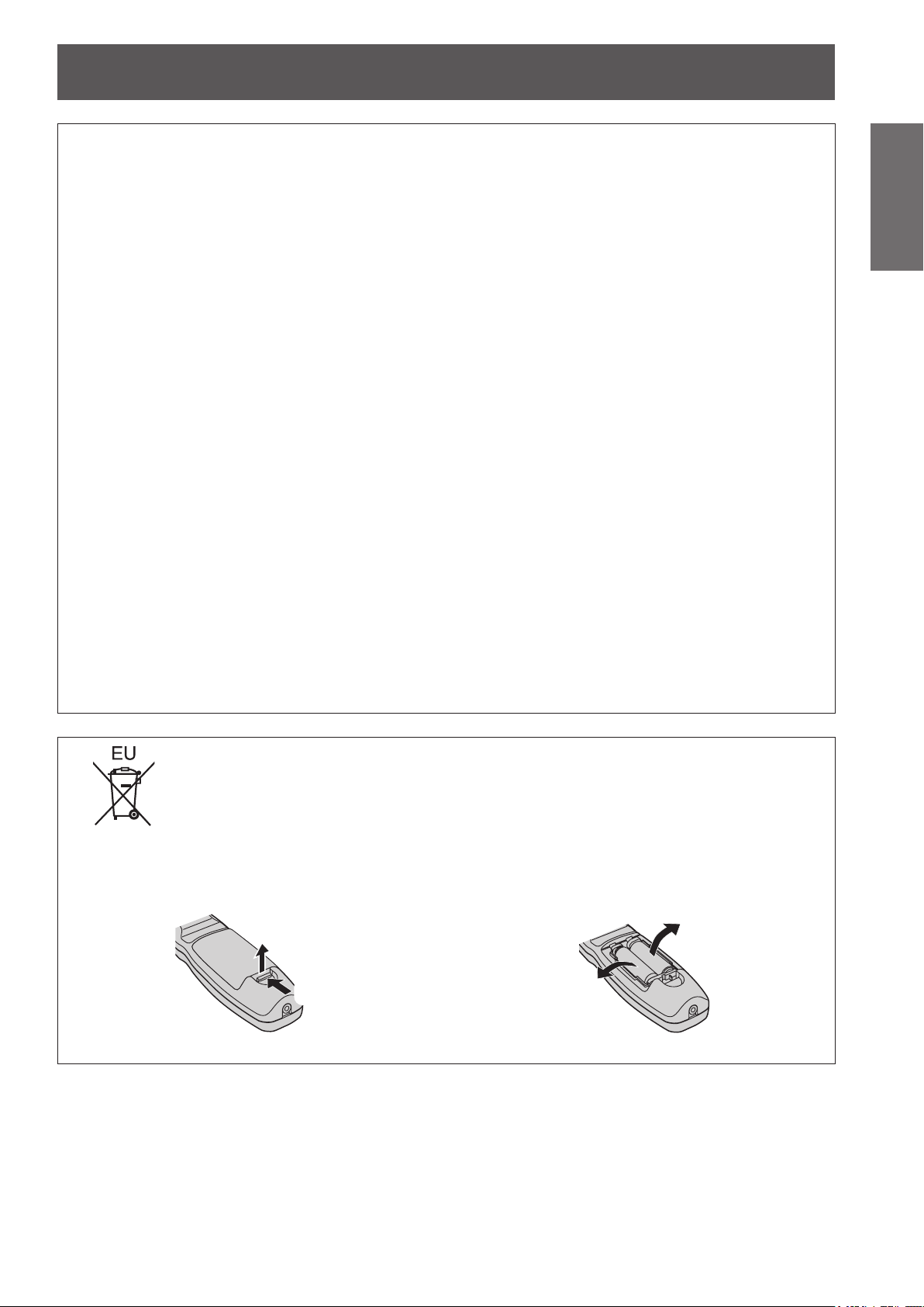
To remove the battery
Remote Control Battery
1. Press the guide and lift the cover.
(ii)
(i)
2. Remove the batteries.
ENGLISH - 7

Read this rst!
Information
Important
Trademarks
• Microsoft
trademarks or trademarks of Microsoft Corporation in the United States and/or other countries.
• Macintosh, Mac OS and Safari are the trademarks of Apple Inc. registered in the United States and other countries.
• PJLink
• HDMI, the HDMI logo and High-Denition Multimedia Interface are trademarks or registered trademarks of HDMI Licensing LLC.
• Other names, company names or product names used in these operating instructions are the trademarks or registered trademarks
of their respective holders.
Please note that the operating instructions do not include the ® and
Illustrations in these operating instructions
• Note that illustrations of the projector and screens may differ from the ones you actually see.
Page references
• In these instructions, references to pages are indicated as: (
Term
• In these instructions, the “Wireless/wired remote control unit” accessories are referred to as the “Remote control”.
®
and its logos, Windows®, Windows® XP, Windows Vista®, Windows® 7, and Internet Explorer® are the registered
TM
is a trademark or pending trademark in Japan, the United States, and other countries and regions.
T
M symbols.
page 00).
8 - ENGLISH
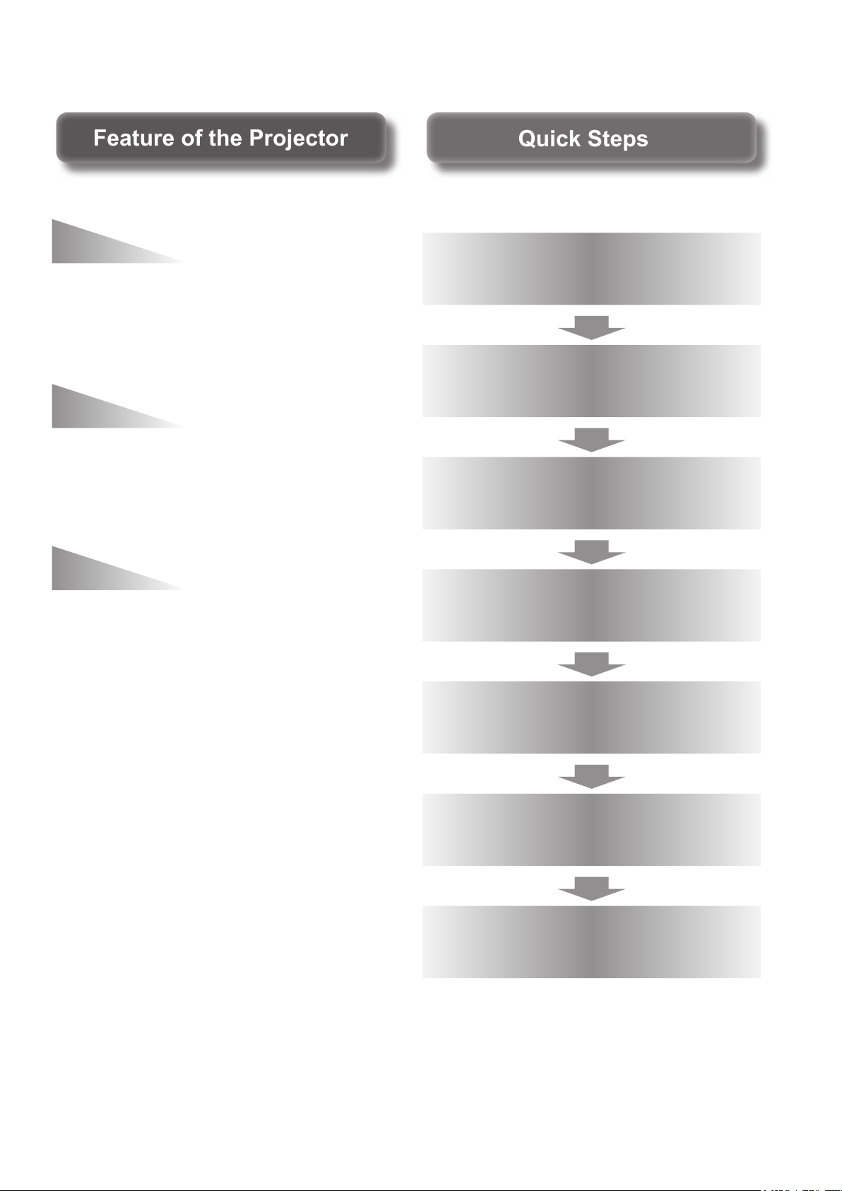
Quick StepsQuick Steps
Feature of the ProjectorFeature of the Projector
High clarity and high color
For details, see the corresponding pages.
reproducibility
▶The unique optical system and lamp
boost control realizes high clarity
and high color reproducibility.
Easy setup and improved
serviceability
▶Extensive lineup of optional lenses
allow more exible setup of the
projector.
Improved cost performance
in maintenance fee
▶The new lter reduces the
maintenance cost.
1. Set up your projector.
( page 21)
2. Attach the projection lens.
( page 29)
3. Connect with other devices.
( page 30)
4. C
onnect the power cord.
( page 32)
5. Power on.
( page 34)
6. Select the input signal.
( page 36)
7. Adjust the image.
( page 36)
ENGLISH - 9

Contents
Contents
Be sure to read “Read this rst!”. (
pages
2 to 8)
Information
Important
Important Information
Read this rst! ............................................ 2
Precautions for Use...................................12
Preparation Getting Started Basic Operation Settings Maintenance Appendix
Preparation
About Your Projector ................................17
Using Remote control .............................. 20
Getting Started
Setting up ...................................................21
Removing/attaching the projection lens
Connections ............................................. 30
Basic Operation
Powering ON/OFF ..................................... 32
Projecting.................................................. 36
Cautions when transporting .............................12
Cautions when installing ..................................12
Security ........................................................... 14
Disposal .......................................................... 14
Cautions on use .............................................. 15
Accessories ....................................................16
Optional accessories ....................................... 16
Remote control ................................................17
Projector body ................................................. 18
Inserting and removing the batteries ................20
Setting Remote control ID numbers ................. 20
Connecting to the projector with a cable ..........20
Projection method ...........................................21
Parts for ceiling mount (optional) ....................21
Screen size and throw distance ....................... 22
Adjustable feet ................................................27
... 28
Removing the projection lens ..........................28
Attaching the projection lens ............................29
Before connecting to the projector ................... 30
Connecting example: AV equipment ............... 31
Connecting example: Computers .................... 31
Connecting the power cord ..............................32
Power indicator ............................................... 33
Powering up the projector ...............................34
Making adjustment and selection .....................34
Powering off the projector ...............................35
Direct power off function ..................................35
Selecting the input signal .................................36
Adjusting the focus, zoom, and shift ...............36
Moving the lens to the home position ..............36
Adjustment range by the lens position shift
(optical shift) ............................................37
Basic operations using the remote control
Using the SHUTTER function ..........................38
Using the on-screen display function ...............38
Switching the input signal ................................38
Using the STATUS function .............................38
Using the automatic setup function ..................39
Using the FUNCTION button ...........................39
Displaying the internal test pattern ...................39
Changing the picture aspect ratio .................... 40
... 38
Settings
Menu Navigation .......................................41
Navigating through the menu ..........................41
MAIN MENU....................................................42
SUB MENU ....................................................42
[PICTURE] menu ...................................... 44
[PICTURE MODE] ...........................................44
[CONTRAST] .................................................. 44
[BRIGHTNESS] ...............................................44
[COLOR] .........................................................45
[TINT] ..............................................................45
[COLOR TEMPERATURE] ..............................45
[WHITE GAIN] .................................................46
[SYSTEM DAYLIGHT VIEW] ........................... 46
[SHARPNESS] ................................................ 46
[NOISE REDUCTION] ..................................... 46
[AI] .................................................................47
[SYSTEM SELECTOR] ...................................47
[POSITION] menu ..................................... 48
[SHIFT] ...........................................................48
[ASPECT] .......................................................48
[ZOOM] ...........................................................49
[CLOCK PHASE] .............................................50
[KEYSTONE] ..................................................50
[ADVANCED MENU] ..................................51
[DIGITAL CINEMA REALITY]...........................51
[BLANKING] .................................................... 51
[INPUT RESOLUTION] ....................................52
[CLAMP POSITION] ........................................52
[EDGE BLENDING] .........................................52
[RASTER POSITION] ......................................53
[DISPLAY LANGUAGE] menu .................. 54
Changing the display language ........................54
[DISPLAY OPTION] menu ........................ 55
[COLOR MATCHING] ......................................55
[COLOR CORRECTION] .................................56
[CONTRAST MODE] .......................................56
[SCREEN SETTING] .......................................57
10 - ENGLISH

Contents
[AUTO SIGNAL] ..............................................57
[AUTO SETUP] ...............................................57
[DVI-D IN] ........................................................58
[ON-SCREEN DISPLAY] .................................58
[BACK COLOR] ..............................................59
[STARTUP LOGO] ..........................................60
[FREEZE] ........................................................ 60
[SIDE BY SIDE]
(PT-DW730E only) ................... 60
[PROJECTOR SETUP] menu ....................61
[PROJECTOR ID] ............................................ 61
[PROJECTION METHOD] ...............................61
[HIGH ALTITUDE MODE] ................................ 61
[COOLING CONDITION] .................................62
[LAMP SELECT] .............................................62
[LAMP RELAY] ................................................63
[LAMP POWER] ..............................................63
[STANDBY MODE] .......................................... 63
[RS-232C] .......................................................63
[REMOTE2 MODE] .........................................64
[STATUS] ........................................................64
[NO SIGNAL SHUT-OFF] ................................65
[FUNCTION BUTTON] ....................................65
[DATE AND TIME] ...........................................65
[SAVE ALL USER DATA] ................................. 65
[LOAD ALL USER DATA] ................................66
[INITIALIZE].....................................................66
[SERVICE PASSWORD] .................................66
[TEST PATTERN] menu ........................... 67
[TEST PATTERN] ............................................67
[SIGNAL LIST] menu ............................... 68
Registering a signal to the list .........................68
Renaming the registered data ........................68
Deleting a registered data ...............................68
Managing the sub memory list ........................69
[SECURITY] menu ................................... 70
[SECURITY PASSWORD] ...............................70
[SECURITY PASSWORD CHANGE] ............... 70
[DISPLAY SETTING] .......................................70
[TEXT CHANGE] ............................................. 71
[MENU LOCK] .................................................71
[MENU LOCK PASSWORD] ...........................71
[CONTROL DEVICE SETUP] ..........................71
[NETWORK] menu ................................... 73
[NETWORK SETUP] .......................................73
[NETWORK CONTROL] .................................73
[NETWORK STATUS] ..................................... 73
Network connections .......................................74
Accessing from the Web browser ...................75
Maintenance
LAMP/TEMP/FILTER Indicators ............... 87
Managing the indicated problems ...................87
Maintenance/Replacement ....................... 89
Before maintaining/replacing the unit ............... 89
Maintenance ...................................................89
Replacing the unit ...........................................90
Troubleshooting ....................................... 93
Appendix
Technical Information ............................... 95
PJLink protocol ................................................95
Control commands via LAN .............................96
Serial terminal ................................................. 98
REMOTE 2 IN terminal .................................. 100
Two window display combination list
(PT-DW730E only) .................................. 101
Menu lock password...................................... 101
List of compatible signals ............................... 102
Specications ..........................................104
Dimensions ..............................................106
Ceiling mount bracket safeguards .........106
Index ........................................................107
Important
Information
PreparationGetting StartedBasic OperationSettingsMaintenanceAppendix
ENGLISH - 11

Precautions for Use
Precautions for Use
Information
Important
Cautions when transporting
Cautions when installing
zProjection lens is susceptible to effects due to vibration or impact. Make sure to remove the lens when transporting.
zWhen transporting the projector, hold it securely by its bottom and avoid excessive vibration and impacts.
Doing so may damage the internal parts and result in malfunctions.
zDo not transport the projector with the adjustable feet extended. Doing so may damage the adjustable feet.
■After installing the projection lens, make sure to attach the projection
lens cover.
zIf the cover is not attached, dust will be accumulated inside and can cause a trouble.
■Do not set up the projector outdoors.
zThe projector is designed for indoor use only.
■Do not use under the following conditions.
zPlaces where vibration and impacts occur such as in a car or vehicle: Doing so may damage the internal
parts and result in malfunctions.
zNear the exhaust of an air conditioner: Depending on the conditions of use, the screen may uctuate due to the hot
air from the air exhaust port or the heated or cooled air from the air conditioner. Take care so that the exhaust from
the projector or other equipment, or the air from the air conditioner does not blow toward the front of the projector.
zNear lights (studio lamps, etc.) where temperature changes greatly (Operating environment ( page 105)):
Doing so may shorten the life of the lamp or result in deformation of the outer case and malfunctions.
zNear high-voltage power lines or near motors: Doing so may interfere with the operation of the projector.
zPlace where there is a high-power laser equipment: It may cause malfunction in DLP chips when the laser
beam enters the lens.
■ Be sure to ask a specialized technician when installing the product to a ceiling.
If the product is to be installed hanging from the ceiling, purchase an optional Ceiling Mount Attachment (For
high ceilings: Model No. ET-PKD56H, For low ceilings: Model No. ET-PKD55S). Please call a specialized
technician or contact an Authorized Service Center for installation.
■Lens Focus
Do not adjust the lens focus in the initial period after switching the projector on. The high clarity projection
lens is thermally affected by the light from the light source, making the focus unstable in the period just after
switching on. Please allow a warm-up time of at least 30 minutes before adjusting the lens focus.
■Make sure to set [HIGH ALTITUDE MODE] to [ON] when using the
projector at elevations of 1 400 m (4 593 ft) or higher and lower than
2 700 m (8 858 ft) above sea level.
Failure to do so may shorten the life of the internal parts and result in malfunctions.
■Make sure to set [HIGH ALTITUDE MODE] to [OFF] when using the
projector at elevations lower than 1 400 m (4 593 ft) above sea level.
Failure to do so may shorten the life of the internal parts and result in malfunctions.
■Do not install the projector at elevations of 2 700 m (8 858 ft) or higher
above sea level.
Failure to do so may shorten the life of the internal parts and result in malfunctions.
12 - ENGLISH
Precautions for Use
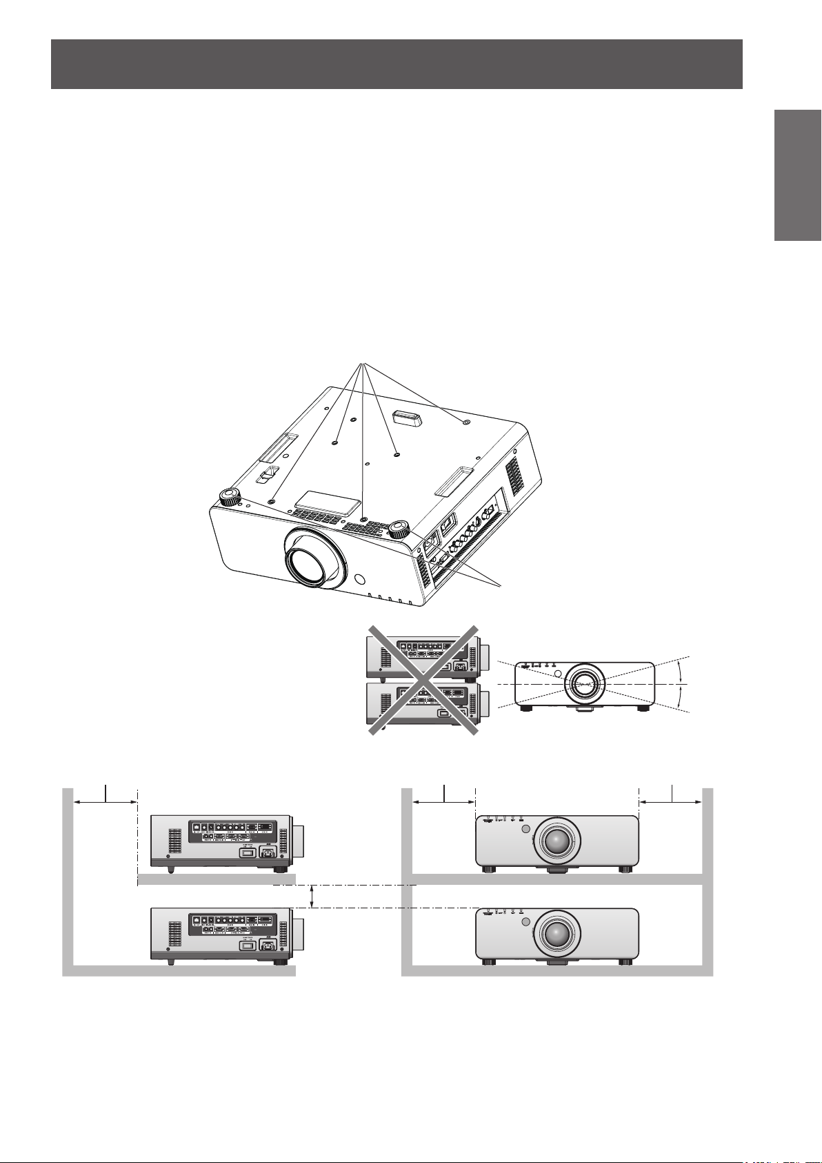
over 500 mm (20") over 500 mm (20") over 500 mm (20")
■Do not use the projector tilted right or left.
Using the projector at a vertical angle that exceeds 15° may reduce product life or result in malfunction.
■When installing and using the projector at an angle that exceeds 30°
vertically, set [COOLING CONDITION] (
Failure to observe this will result in malfunctions or the lamp life or other components will be shortened.
■Cautions when setting the projectors
zWhen installing and using the projector with a method other than the oor standing installation using the
adjustable feet, x the projector using the ve screw holes for ceiling mounting (shown in the gure).
(Screw diameter: M6, tapping depth inside the set: 12 mm)
zUse the adjustable feet only for the oor standing installation and for adjusting the angle. If you use it other
than this purpose, the set may be damaged.
Screw holes for ceiling mount (M6)
page 62).
Important
Information
Adjustable feet
zDo not stack the projectors.
zDo not use the projector tilted at an angle
that exceeds ±15° vertically.
zDo not block the ventilation ports (intake
and exhaust) of the projector.
zAvoid heating and cooling air from the air
conditioning system directly blow to the
ventilation ports (intake and exhaust) of the
projector.
over 100 mm (4")
+15°
–15°
zDo not install the projector in a conned space.
When it is necessary to install in a conned space, install the air conditioning or ventilating installation
separately. Exhaust heat may accumulate when the ventilation is not enough, triggering the protection
circuit of the projector.
zMake a clearance of at least 20 mm between the projector bottom and setting surface by inserting spacers
(metallic) etc. between them.
ENGLISH - 13

Precautions for Use
Information
Important
Security
Take safety measures against following incidents.
Take sufcient security measures. ( page 70)
Disposal
To dispose of the product, inquire your local authorities or dealer for correct methods of disposal.
The lamp contains mercury. When disposing of used lamp units, contact your local authorities or dealer for correct
methods of disposal.
zPersonal information being leaked via this product
zUnauthorized operation of this product by a malicious third party
zInterfering or stopping of this product by a malicious third party
zMake your password as difcult to guess as possible.
zChange your password periodically.
zPanasonic or its afliate company never inquires a password directly to a customer. Do not tell your
password in case you receive such an inquiry.
zThe connecting network must be secured by rewall or others.
zSet a password and restrict the users who can log in.
14 - ENGLISH

Precautions for Use
Cautions on use
■In order to get the picture quality
Draw curtains or blinds over windows and turn off any lights near the screen to prevent outside light or light
from indoor lamps from shining onto the screen.
■Do not touch the surface of the projection lens with your bare hands.
If the surface of the lens becomes dirty from ngerprints or anything else, this will be magnied and projected
onto the screen. Please put the lens cover (accessory) on the projector when you do not use it.
■DLP chips
zThe DLP chips are precision-made. Note that in rare cases, pixels of high precision could be missing or
always lit, but this is not a malfunction.
zDirecting a high power laser beam onto the lens surface can damage the DLP chip.
■Do not move the projector while it is operating or subject it to vibration
or impact.
The service life of its internal motor will be shortened.
■Lamp
The luminous source of the projector is a mercury lamp with high internal pressure.
A high pressure mercury lamp has following characteristics.
zThe brightness of the lamp will decrease by duration of usage.
zThe lamp may burst with sound or shorten life by shock or chipping.
zThe life of the lamp varies greatly depending on individual specicities and usage conditions. In particular,
continuous use over 22 hours and frequent on/off switching of the power greatly deteriorate the lamp and
affect the lamp life.
zLamp deterioration accelerates when used continuously for 22 hours or more. Lamp deterioration due to
continuous use can be reduced by using the LAMP RELAY function ( page 63).
zIn rare cases, the lamp burst shortly after the projection.
zThe risk of bursting increases when the lamp is used beyond its replacement cycle. Make sure to replace
the lamp unit consistently. (“When to replace the lamp unit” ( page 91), “Replacing the lamp unit” ( page 92))
zIf the lamp bursts, gas contained inside of the lamp is released in a form of smoke.
zIt is recommended to store replacement lamps for contingency.
Important
Information
<Software information regarding this product>
© Panasonic Corporation 2011
This product incorporates the following software:
(1)the software which is developed independently by or for Panasonic Corporation
(2)the software which is licensed under the GNU GENERAL PUBLIC LICENSE,
and
(3)the software which is licensed under the GNU LESSER GENERAL PUBLIC LICENSE.
For the software categorized as (2) and (3), the license is available in accordance with GNU GENERAL PUBLIC
LICENSE and GNU LESSER GENERAL PUBLIC LICENSE respectively. As for the terms and conditions,
please refer to the software licence of the supplied CD-ROM.
If you wish to ask any questions as to the software, please contact (sav.pj.gpl.pavc@ml.jp.panasonic.com) by email.
Pursuant to at the directive 2004/108/EC, article 9(2)
Panasonic Testing Centre
Panasonic Service Europe, a division of Panasonic Marketing Europe GmbH
Winsbergring 15, 22525 Hamburg, F.R. Germany
ENGLISH - 15
Precautions for Use
Information
Important
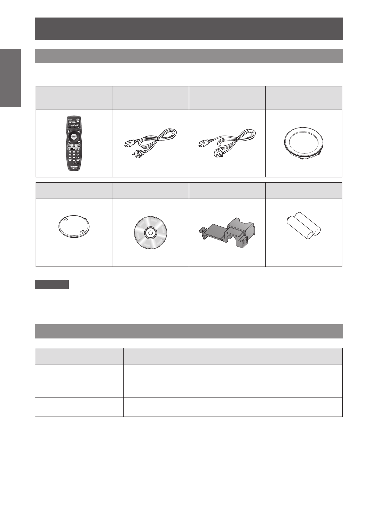
Accessories
Make sure that the following accessories are provided with your projector. Numbers in the brackets ( ) show the
number of accessories.
Wireless/wired remote
control unit (x1)
(N2QAYB000371)
Lens cover (x1)
(TKKL5244)
Power cord (x1)
(K2CM3FZ00003)
CD-ROM (x1)
(TXFQB02VKP8)
Power cord (x1)
(K2CT3FZ00003)
Power cord secure lock
(x1) (TTRA0183)
Projection lens cover (x1)
(TKPB35101)
AA/R6 battery (x2)
(Only for the model with a lens)
Attention
zAfter unpacking the projector, discard the power cord cap and packaging material properly.
zFor lost accessories, consult your dealer.
zThe part numbers of accessories and separately sold components are subject to change without notice.
zStore small parts in an appropriate manner, and keep them away from young children.
(For remote control unit)
Optional accessories
Optional accessories
(product name)
Projection lens
Ceiling mount bracket ET-PKD56H (for high ceilings), ET-PKD55S (for low ceilings)
Replacement lamp unit ET-LAD60A (1 pc), ET-LAD60AW
Replacement lter unit ET-EMF300
Model No.
ET-DLE055 (xed-focus lens), ET-DLE080 (ultra short-focus zoom lens),
ET-DLE150 (short-focus zoom lens), ET-DLE250 (medium-focus zoom lens),
ET-DLE350 (long-focus zoom lens), ET-DLE450 (ultra long-focus zoom lens)
(2 pcs)
16 - ENGLISH
About Your Projector
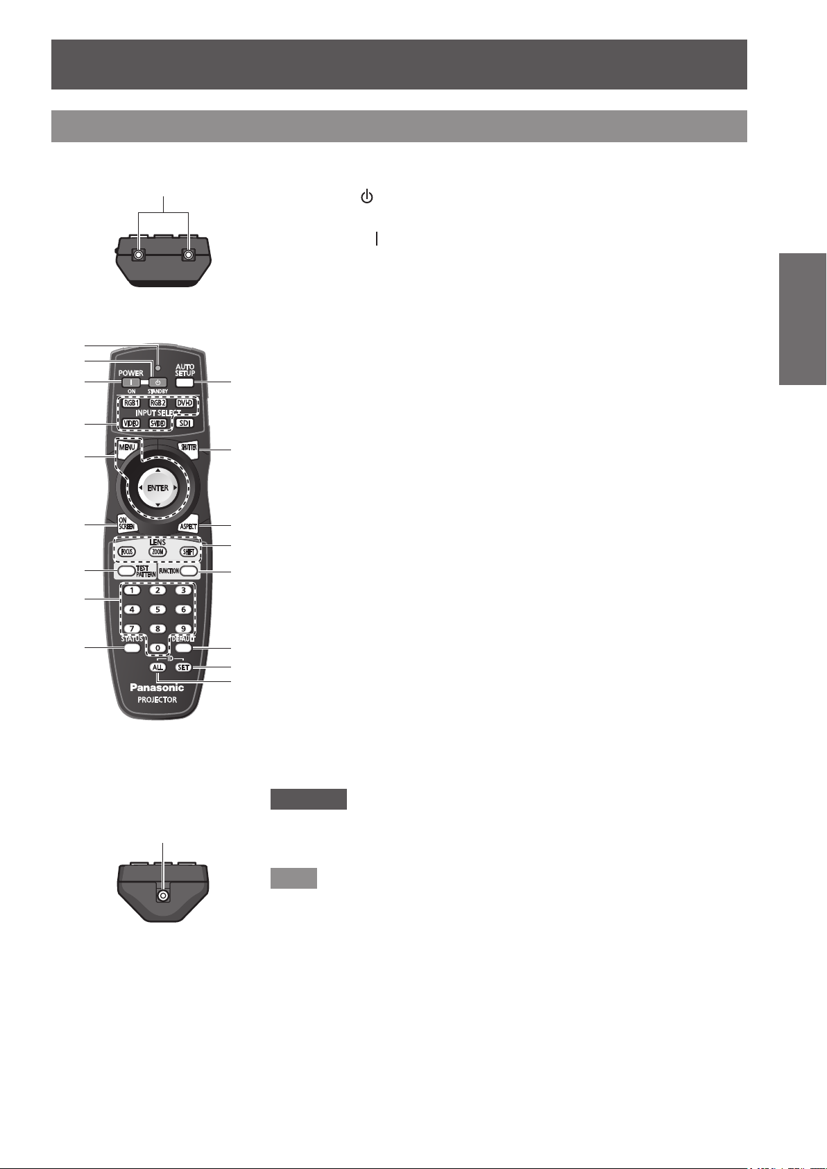
Remote control signal emitters
(1)
Remote control wired terminal
Remote control
About Your Projector
■Top
■Front
(2)
(3)
(4)
(5)
(6)
(7)
(8)
(9)
(1) Remote control indicator
Flashes by pressing any buttons.
(2)
STANDBY (
Sets the projector to the standby mode when the <MAIN POWER> switch on the
projector is set to <ON>.
(3)
POWER ON (
Starts projection when the <MAIN POWER> switch on the projector is set to <ON>
and in the standby mode.
Input Selection (<RGB1>, <RGB2>, <DVI-D>, <VIDEO>, and <S-VIDEO>) buttons
(4)
Switches the input signal to project. ( page 38)
(5) <MENU> button/<ENTER> button/ ▲▼◀▶ buttons
Use it to operate the menu screen. (
(6) <ON SCREEN> button
Switches on (display)/off (not display) the on-screen display function. (
(7) <TEST PATTERN> button
(10)
(11)
(12)
(13)
(14)
(15)
(16)
(17)
Displays the test pattern. (
(8) Number (<0> - <9>) buttons
Use it when the system uses multiple projectors.
Used to input the ID numbers or passwords.
(9) <STATUS> button
Displays the information of the projector.
(10) <AUTO SETUP> button
Automatically adjusts the image display position while projecting the image.
[PROGRESS] is displayed o
page 39)
(
(11) <SHUTTER> button
Use it to temporarily turn off the image. (
(12) <ASPECT> button
Switches the aspect ratio of the image. (
(13) Lens (<FOCUS>, <ZOOM>, and <SHIFT>) buttons
Adjusts the projection lens. (
(14) <FUNCTION> button
You can assign a frequently used operation and use as a shortcut button. (
(15) <DEFAULT> button
Restores the contents of the sub-menu to the factory default setting. (
(16) <ID SET> button
Sets the ID number of the remote control when the system uses multiple projectors.
page 20)
(
(17) <ID ALL> button
Simultaneously controls all the projectors with one remote control when the system
uses multiple projectors. (
) button
) button
page 39)
n the screen while the image is adjusted automatically.
pages 34, 36)
page 20)
page 41)
page 38)
page 40)
page 38)
page 41)
page 39)
Preparation
■Bottom
( page 20)
Attention
zDo not drop the remote control.
oid contact with liquids or moisture.
zAv
zDo not attempt to modify or disassemble the remote control.
Note
zThe <SDI> button cannot be used.
zThe remote control can be used within a distance of about 30 m if pointed
directly at the remote control receiver. The remote control can control
at angles of up to ±15° vertically and ±30° horizontally, but the effective
control range may be reduced.
zIf there are any obstacles between the remote control and the remote
ontrol signal receptor, the remote control may not operate properly. The
c
signal will be reected off the screen, but the operating range may differ
due to the screen material.
zIf the remote control signal receptor receives strong light such as
uorescent light directly, the remote control may not operate properly. Use
it in a place distant from the light source.
ENGLISH - 17
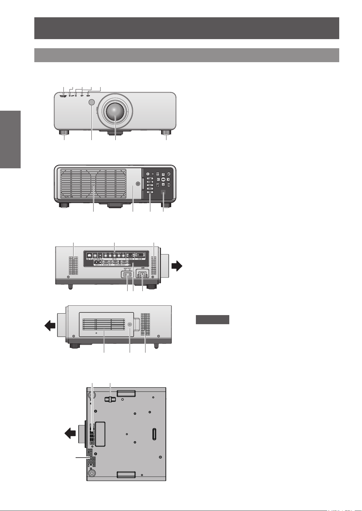
About Your Projector
(1) (2) (3) (4) (5)
(13) (14) (13)
(19)(13)
Projector body
Preparation
■Front
(6) (7) (8) (6)
■ Rear
(9) (10) (11) (12)
■Side
(15)(16) (17)
Front
(1) Power indicator <STANDBY (RED)/ON (GREEN)>
Displays the status of the power.
(2) Lamp indicator <LAMP1>
Displays the status of the lamp 1.
(3) Lamp indicator <LAMP2>
Displays the status of the lamp 2.
(4) Temperature indicator <TEMP>
Displays the status of the internal temperature.
(5) Filter indicator <FILTER>
Displays the status of the air lter unit.
(6) Adjustable feet
Adjusts the projection angle.
emote control signal receiver (front)
) R
(7
(8) Projection lens
(Only for the model with a lens)
(9) Air exhaust port
(10) Lamp unit cover (
(11) Control panel (
(12) Remote control signal receiver (rear)
(13) Air intake port
(14) Terminals on side (
(15) <MAIN POWER> switch
Turns off/on the main power.
(16) Security slot
This security slot is compatible with the Kensington
security cables.
C IN terminal <AC IN>
(17) A
Connect the supplied power cord.
(18) Air lter cover
There is an air lter unit inside. (
(19) Burglar hook port
Attach a commercial burglar prevention cable.
page 19)
page 92)
page 19)
page 89)
Front
■ Bottom
Front
(13)
(13) (18) (13)
Attention
zKeep your hands and other objects away from the
air exhaust port.
– Keep your hands and face away.
– Do not insert your ngers.
– Keep heat-sensitive articles away.
Heated air from the air outlet port can cause burns,
njury, or deformations.
i
18 - ENGLISH
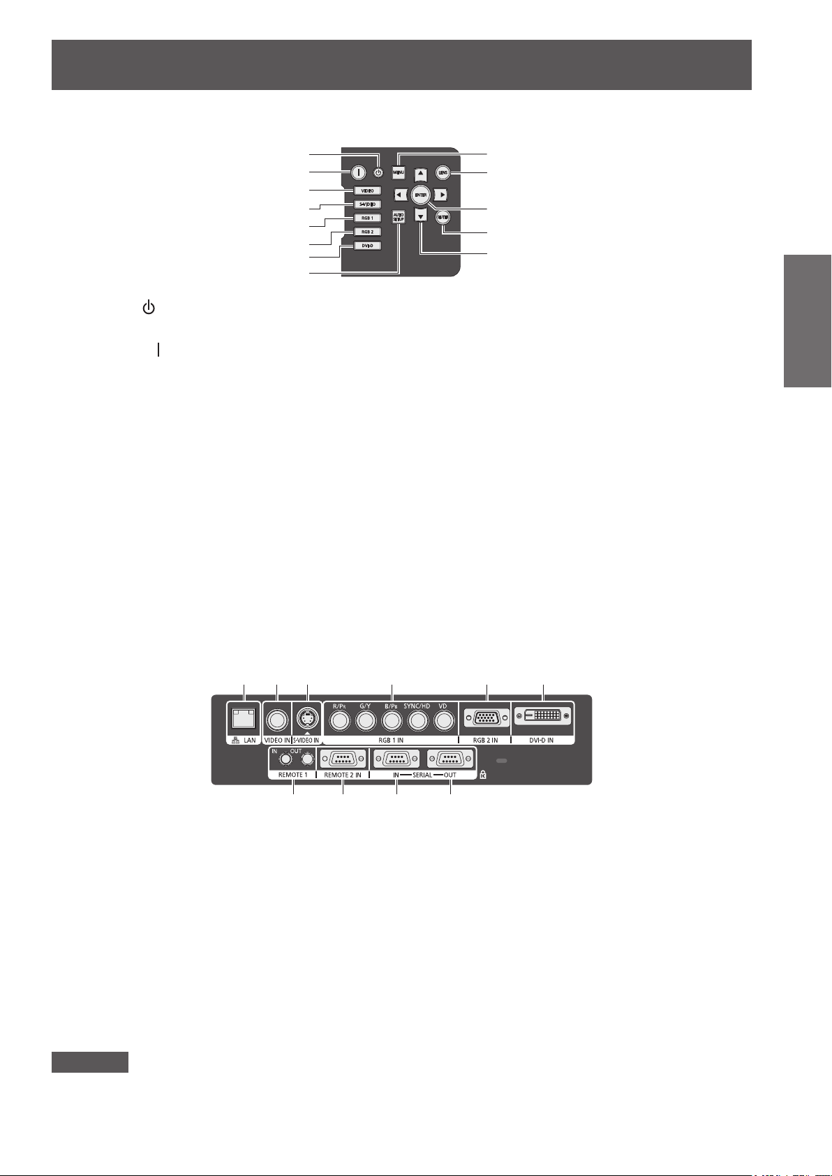
■Control panel
(1) (2) (3) (4) (5) (6)
(7) (8) (9) (10)
About Your Projector
(1)
(2)
(3)
(4)
(5)
(6)
(7)
(8)
(1)
STANDBY (
Sets the projector to the standby mode when the <MAIN
POWER> switch on the projector is set to <ON>.
(2)
POWER ON (
Starts projection when the <MAIN POWER> switch on the
projector is set to <ON> and in the standby mode.
(3) <VIDEO> button
Switches to VIDEO input.
(4) <S-VIDEO> button
Switches to S-VIDEO input.
(5) <RGB1> button
Switches to RGB1 input.
(6) <RGB2> button
Switches to RGB2 input.
(7) <DVI-D> button
Switches to DVI-D input.
(8) <AUTO SETUP> button
Automatically adjusts the image display position while
rojecting the image.
p
[
PROGRESS] is displayed on the screen while the image
is adjusted automatically. (
) button
) button
page 39)
(9)
(10)
(11)
(12)
(13)
(9) <MENU> button
Displays and clears the main menu, and returns to the
previous menu when the menu is displayed. (
If you press the <MENU> button on the control panel for
at least three seconds while the on-screen indication is off,
the screen off state is canceled.
(10) <LENS> b
A
djusts the focus, zoom, and shift (position) of the lens.
(11) <ENTER> button
Press to activate a menu selection or to initiate a function.
(12) <SHUTTER> button
Use this button to temporarily turn off the image. (
(13) ▲▼◀▶ buttons
Use these buttons to select menu items, change settings,
and adjust levels. It is also used to enter the [SECURITY]
password.
utton
page 41)
Preparation
page 38)
■Terminals on side
(1) LAN terminal <LAN>
This is a terminal to connect to the network.
(2) VIDEO input terminal <VIDEO IN>
This is a terminal to input the VIDEO signal.
(3) S-VIDEO input terminal <S-VIDEO IN>
This is a terminal to input the S-VIDEO signal.
(4) RGB (YP
Y>, <B/P
This is a terminal to input the RGB signal or the YPBPR signal.
(5) RGB2 input terminal <RGB 2 IN>
This is a terminal to input the RGB signal or the YPBPR signal.
(6) DVI-D input terminal <DVI-D IN>
This is a terminal to input the DVI-D signal.
Attention
zConnect the LAN to the indoor equipment.
) 1 input terminals <RGB 1 IN> (<R/PR>, <G/
BPR
>, <SYNC/HD>, and <VD>)
B
(7) REMOTE 1 IN terminal <REMOTE 1 IN>/REMOTE 1 OUT
terminal <REMOTE 1 OUT>
These are the terminals to connect the remote control for
serial control when the system uses multiple projectors.
(8) REMOTE 2 IN terminal <REMOTE 2 IN>
This is a te
external control circuit.
(9) SERIAL IN terminal <SERIAL IN>
This is a RS-232C compatible terminal to externally control
the projector by connecting a computer.
(10) SERIAL OUT terminal <SERIAL OUT>
This is a terminal to output the signal connected to the
SERIAL IN terminal.
rminal to
remotely control the projector using the
ENGLISH - 19
Using Remote control
Connecting terminals
Using Remote control
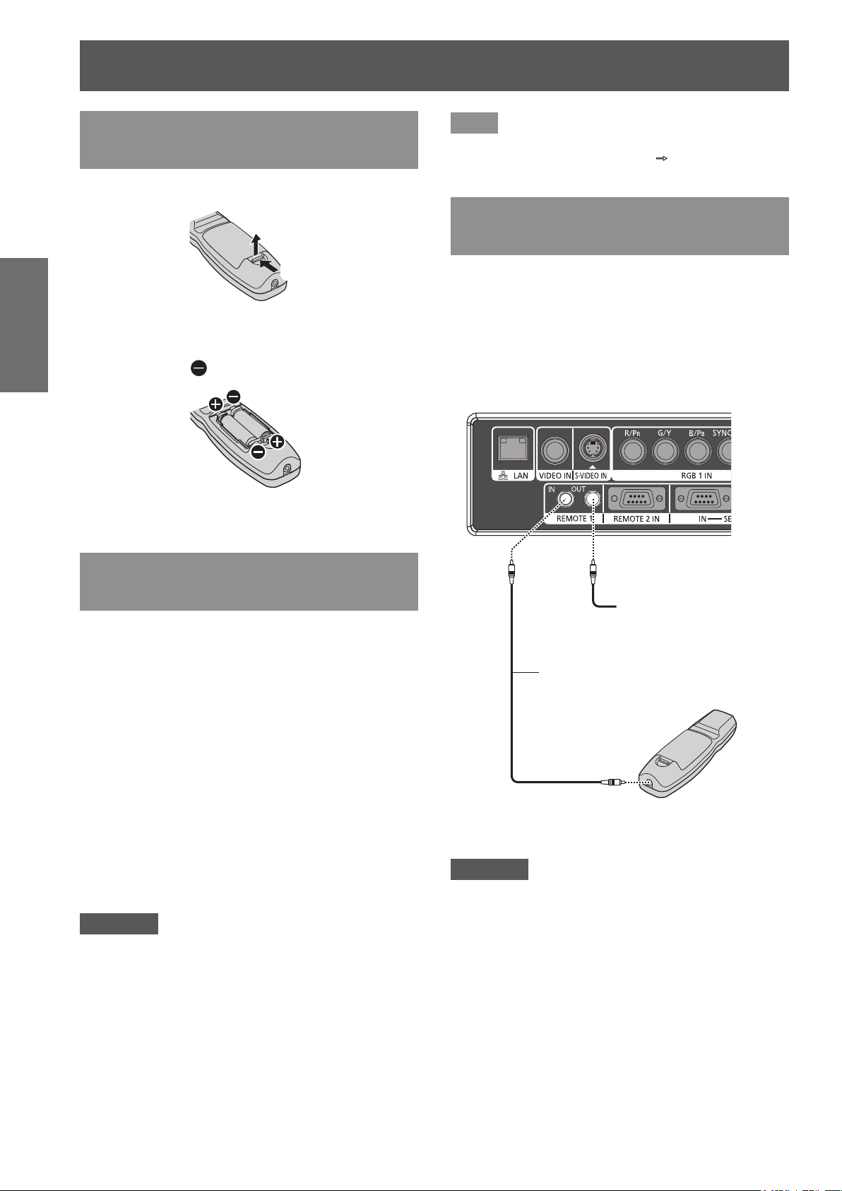
Inserting and removing the batteries
1) Open the cover.
Preparation
2) Insert the batteries and close the cover
(ii)
(i)
(insert the
zWhen remove the batteries, perform the steps
in the reverse order.
side rst).
Note
zSet the ID number of the projector from the
[PROJECTOR SETUP] menu
page 61).
(
[PROJECTOR ID]
Connecting to the projector with a cable
When you use the system with multiple projectors,
congure the units as in the following gure. Use a
commercial M3 stereo mini jack cable and connect
the other devices to the <REMOTE 1 IN>/<REMOTE
1 OUT> terminals of the projector.
It is effective to use the remote control in a place
where an obstacle stands in the light path or where
devices are susceptible to the outside light.
Setting Remote control ID numbers
When you use the system with multiple projectors,
you can operate all the projectors simultaneously or
each projector individually using single remote control,
if a unique ID number is assigned to each projector.
After setting the ID number of the projector, set same
ID number on the remote control.
The ID number of the projector is set to [ALL] by
the factory default. When using a single projector,
press the <ID ALL> button on the remote control.
1) Press the <ID SET> button on the
2) Within ve seconds, press the two-
Attention
zSince setting of the ID number on the remote
control can be performed even without the projector,
do not press the <ID SET> button carelessly. If the
number (<0> - <9>) button is not pressed within ve
seconds after the <ID SET> button is pressed, the
ID number returns to that before pressing the <ID
SET> button.
zThe ID number set on the remote control will
be stored unless it is set again. However, it will
be erased if the remote control is left with dead
batteries. Set the same ID number again when the
batteries are replaced.
■ How to set
remote control.
digit ID number set on the projector
using the number (<0> - <9>) button.
Connect to the
secondary projector
M3 stereo mini jack cable
(commercial)
Remote
control
Connect to the remote control
wired terminal
Attention
zUse a cable that is 15 m or shorter, with 2 core
shield. The remote control may not operate when
the length of the cable exceeds 15 m or when the
shielding of the cable is inadequate.
20 - ENGLISH
Setting up
Setting up
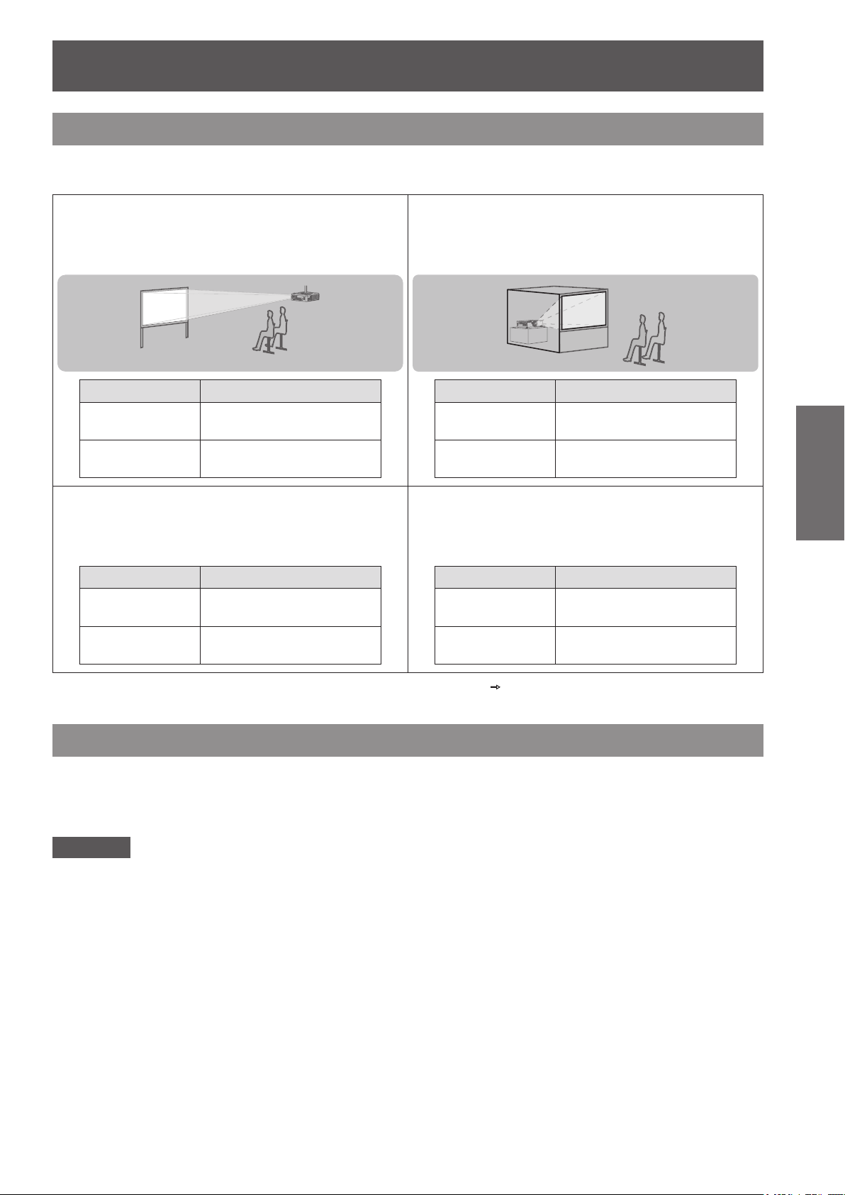
Projection method
You can use the projector with any of the following four projection methods. Select the appropriate method
depending on the environment.
■Mounting on the ceiling and
projecting forward
Menu item
[PROJECTION
METHOD]
[COOLING
CONDITION]
*1
Method
[FRONT/CEILING]
[CEILING SETTING]
■Mounting on the ceiling and
projecting from rear
(Using the translucent screen)
Menu item
[PROJECTION
METHOD]
[COOLING
CONDITION]
*1
Method
[REAR/CEILING]
[CEILING SETTING]
■Setting on a desk/oor and
projecting from rear
(Using the translucent screen)
Menu item
[PROJECTION
METHOD]
[COOLING
CONDITION]
*1
Method
[REAR/FLOOR]
[FLOOR SETTING]
■Setting on a desk/oor and
projecting forward
Menu item
[PROJECTION
METHOD]
[COOLING
CONDITION]
*1
Method
[FRONT/FLOOR]
[FLOOR SETTING]
Getting Started
*1: For details of the menu items, conrm from the [PROJECTOR SETUP] menu
[COOLING CONDITION] (
page 62).
[PROJECTION METHOD] (
page 61) and
Parts for ceiling mount (optional)
You can install the projector on the ceiling using the optional ceiling mount bracket (ET-PKD56H: for high ceilings,
ET-PKD55S: for low ceilings).
zUse only the ceiling mount brackets specied for this projector.
zRefer to the installation manual for the ceiling mount bracket when you install the bracket and the projector.
Attention
zTo ensure the projector performance and security, installation of the ceiling mount bracket must be carried out
by your dealer or a qualied technician.
ENGLISH - 21
Setting up
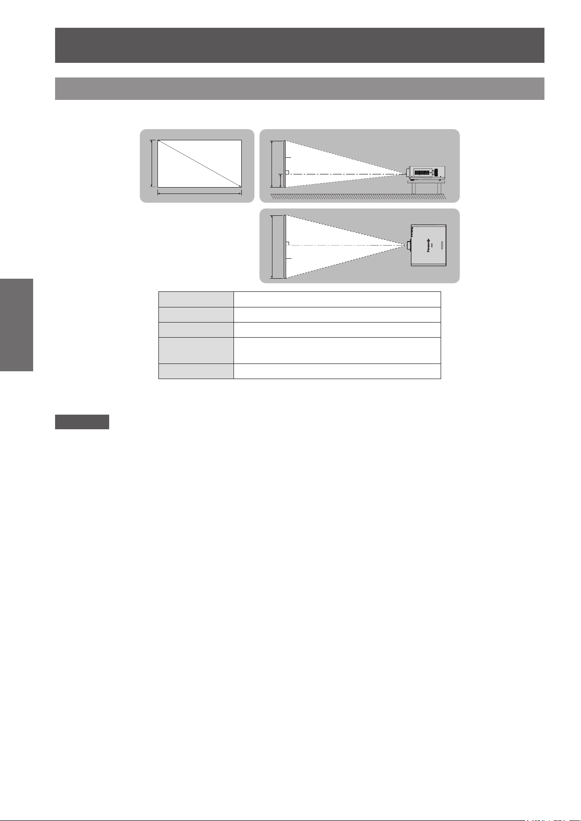
Screen size and throw distance
Install the projector referring to the following gures and table describing projection distances. Image size and
image position can be adjusted in accordance with the screen size and screen position.
Projected image
Getting Started
Attention
zRead “Precautions for Use” (
zDo not use the projector and the high-powered laser equipment in the same room.
Hitting of a laser beam on to the lens can damage the DLP chips.
SH
SD
SW
L (LW/LT)
*1
Projection distance (m)
SW SH
Screen
L (LW/LT)
H
L (LW/LT)
Screen
SH Image height (m)
SW Image width (m)
H
Distance from the center of lens to the image
lower end (m)
SD Image diagonal size (m)
*1: LW: Minimum projection distance when the zoom lens is used
LT: Maximum projection distance when the zoom lens is used
pages 12 to 16) before installation.
22 - ENGLISH
Setting up
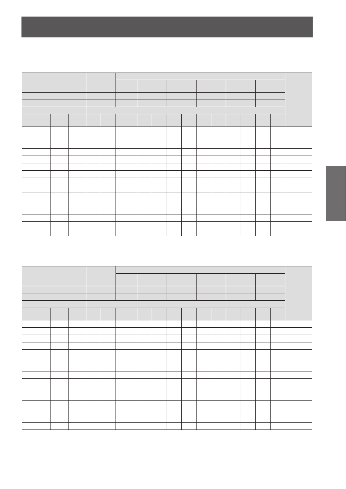
■Projection distance per projection lens (for PT-DW730E)
zWhen the screen aspect ratio is 16:10 (unit: m)
(All measurements below are approximate and may differ slightly from the actual measurements.)
Lens type
Projection lens Model No. –
Throw ratio
Projection size Projection distance (L)
Screen size
(SD)
1.27 (50") 0.673 1.077 1.91 2.70 0.87 0.87 1.09 1.45 2.12 2.54 4.06 4.00 6.11 5.96 9.60 -0.07–0.34
1.52 (60") 0.808 1.292 2.31 3.26 1.06 1.05 1.32 1.75 2.55 3.07 4.89 4.83 7.36 7.21 11.57 -0.08–0.40
1.78 (70") 0.942 1.508 2.71 3.81 1.24 1.24 1.54 2.05 2.98 3.59 5.72 5.65 8.61 8.46 13.55 -0.09–0.47
2.03 (80") 1.077 1.723 3.11 4.37 1.42 1.42 1.77 2.35 3.42 4.12 6.55 6.48 9.86 9.71 15.53 -0.11–0.54
.29 (90") 1.212 1.939 3.50 4.92 1.61 1.60 2.00 2.65 3.85 4.64 7.38 7.31 11.11 10.96 17.51 -0.12–0.61
2
2.54 (100") 1.346 2.154 3.90 5.48 1.79 1.78 2.22 2.95 4.28 5.17 8.20 8.13 12.36 12.22 19.49 -0.14–0.67
3.05 (120") 1.615 2.585 4.70 6.59 2.16 2.15 2.68 3.55 5.15 6.21 9.86 9.79 14.86 14.72 23.45 -0.16–0.81
3.81 (150") 2.019 3.231 5.89 8.25 2.71 2.70 3.36 4.45 6.45 7.79 12.35 12.27 18.61 18.47 29.38 -0.20–1.01
5.08 (200") 2.692 4.308 7.88 11.03 3.63 3.62 4.49 5.95 8.61 10.41 1
6.35 (250") 3.365 5.385 9.86 13.81 – 4.53 5.62 7.45 10.78 13.03 20.63 20.53 31.10 30.99 49.17 -0.34–1.68
7.62 (300") 4.039 6.462 11.85 16.58 – 5.45 6.76 8.96 12.95 15.65 24.77 24.67 37.35 37.25 59.06 -0.40–2.02
8.89 (350") 4.712 7.539 13.84 19.36 – 6.36 7.89 10.46 15.11 18.28 28.91 28.80 43.59 43.51 68.96 -0.47–2.36
10.16 (400") 5.385 8.616 15.83 22.13 – 7.28 9.02 11.96 17.28 20.90 33.06 32.94 49.84 49.76 78.85 -0.54–2.69
12.70 (500") 6
15.24 (600") 8.077 12.923 23.78 33.23 – 10.94 13.56 17.96 25.94 31.39 49.62 49.47 74.82 74.80
*1
Height
Width
SH)
(SW)
(
.731 10.770 19.80 27.68 – 9.11 11.29 14.96 21.61 26.14 41.34 41.20 62.33 62.28 98.64 -0.67–3.37
Standard
zoom lens
1.8–2.5:1 0.8:1 0.8–1.0:1 1.4–2.0:1 2.4–3.8:1 3.8–5.7:1 5.6–9.0:1
Min. Max. Fixed Min. Max. Min. Max. Min. Max. Min. Max. Min. Max.
Fixed-
focus lens
ET-DLE055
Ultra short-
focus zoom lens
ET-DLE080 ET-DLE150 ET-DLE250 ET-DLE350 ET-DLE450
*1: The throw ratio is based on the value during projection onto a 2.03-m (80") screen size.
*2: When the xed-focus lens (ET-DLE055) is attached, the lens shift cannot be used, so the height position (H) will be SH/2.
zWhen the screen aspect ratio is 16:9 (unit: m)
(All measurements below are approximate and may differ slightly from the actual measurements.)
Lens type
Projection lens Model No. –
Throw ratio
Projection size Projection distance (L)
Screen size
(SD)
1.27 (50") 0.623 1.107 1.97 2.78 0.90 0.89 1.12 1.49 2.18 2.62 4.18 4.11 6.29 6.13 9.87 -0.14–0.31
1.52 (60") 0.747 1.328 2.38 3.35 1.09 1.08 1.35 1.80 2.62 3.15 5.03 4.96 7.57 7.42 11.90 -0.16–0.37
1.78 (70") 0.872 1.550 2.79 3.92 1.28 1.27 1.59 2.11 3.07 3.69 5.88 5.81 8.85 8.70 13.94 -0.19–0.44
2.03 (80") 0.996 1.771 3.19 4.49 1.46 1.46 1.82 2.42 3.51 4.23 6.73 6.66 10.14 9.99 15.97 -0.22–0.50
.29 (90") 1.121 1.992 3.60 5.06 1.65 1.65 2.05 2.72 3.96 4.77 7.58 7.51 11.42 11.28 18.01 -0.25–0.56
2
2.54 (100") 1.245 2.214 4.01 5.63 1.84 1.84 2.29 3.03 4.40 5.31 8.44 8.36 12.71 12.56 20.04 -0.27–0.62
3.05 (120") 1.494 2.657 4.83 6.77 2.22 2.21 2.75 3.65 5.29 6.39 10.14 10.06 15.27 15.14 24.11 -0.33–0.75
3.81 (150") 1.868 3.321 6.05 8.49 2.79 2.78 3.45 4.58 6.63 8.01 12.69 12.61 19.13 19.00 30.21 -0.41–0.93
5.08 (200") 2.491 4.428 8.10 11.34 3.73 3.72 4.62 6.12 8.86 10.70 1
6.35 (250") 3.113 5.535 10.14 14.19 – 4.66 5.78 7.66 11.08 13.40 21.21 21.11 31.97 31.86 50.54 -0.69–1.56
7.62 (300") 3.736 6.641 12.18 17.04 – 5.60 6.94 9.21 13.31 16.09 25.46 25.36 38.39 38.29 60.71 -0.82–1.87
8.89 (350") 4.358 7.748 14.23 19.90 – 6.54 8.11 10.75 15.53 18.79 29.72 29.61 44.81 44.72 70.88 -0.96–2.18
10.16 (400") 4.981 8.855 16.27 22.75 – 7.48 9.27 12.29 17.76 21.48 33.98 33.86 51.23 51.16 81.05 -1.10–2.49
12.70 (500") 6
15.24 (600") 7.472 13.283 24.44 34.16 – 11.24 13.93 18.46 26.67 32.26 51.00 50.85 76.91 76.89
*1
Height
Width
SH)
(SW)
(
.226 11.069 20.36 28.46 – 9.36 11.60 15.38 22.21 26.87 42.49 42.35 64.07 64.02
*1: The throw ratio is based on the value during projection onto a 2.03-m (80") screen size.
*2: When the xed-focus lens (ET-DLE055) is attached, the lens shift cannot be used, so the height position (H) will be SH/2.
Standard
zoom lens
1.8–2.5:1 0.8:1 0.8–1.0:1 1.4–2.0:1 2.4–3.8:1 3.8–5.7:1 5.6–9.0:1
Min. Max. Fixed Min. Max. Min. Max. Min. Max. Min. Max. Min. Max.
Fixed-
focus lens
ET-DLE055
Ultra short-
focus zoom lens
ET-DLE080 ET-DLE150 ET-DLE250 ET-DLE350 ET-DLE450
Optional lens
Short-focus
zoom lens
Optional lens
Short-focus
zoom lens
Medium-focus
zoom lens
6.49 16.40 24.85 24.73 39.28 -0.27–1.35
Medium-focus
zoom lens
6.95 16.86 25.55 25.43 40.38 -0.55–1.25
Long-focus
zoom lens
Long-focus
zoom lens
Ultra long-focus
zoom lens
118.43
Ultra long-focus
zoom lens
101.39
121.73
Height
position
*2
(H)
-0.81–4.04
Height
position
*2
(H)
-1.37–3.11
-1.64–3.74
Getting Started
ENGLISH - 23
Setting up
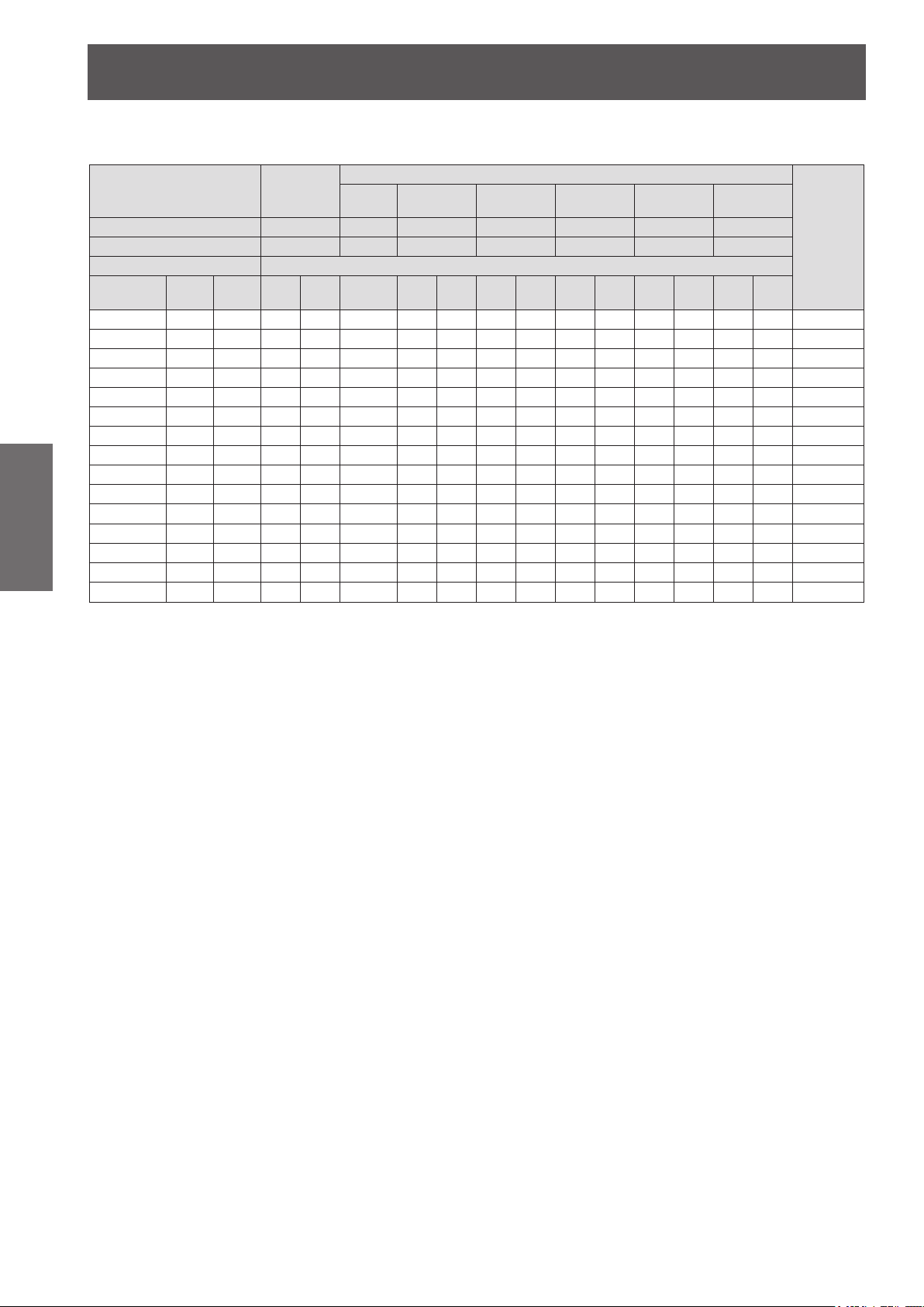
zWhen the screen aspect ratio is 4:3 (unit: m)
(All measurements below are approximate and may differ slightly from the actual measurements.)
Projection lens Model No. –
Projection size Projection distance (L)
Screen size
(SD)
1.27 (50") 0.762 1.016 2.18 3.07 0.99 0.99 1.24 1.65 2.40 2.89 4.61 4.54 6.94 6.78 10.90 -0.08–0.38
1.52 (60") 0.914 1.219 2.63 3.70 1.20 1.20 1.50 1.99 2.89 3.48 5.55 5.48 8.35 8.20 13.14 -0.09–0.46
1.78 (70") 1.067 1.422 3.08 4.33 1.41 1.40 1.75 2.33 3.38 4.08 6.48 6.42 9.76 9.62 15.38 -0.11–0.53
2.03 (80") 1.219 1.626 3.53 4.95 1.62 1.61 2.01 2.67 3.87 4.67 7.42 7.35 11.18 11.03 17.62 -0.12–0.61
.29 (90") 1.372 1.829 3.98 5.58 1.83 1.82 2.27 3.01 4.36 5.26 8.36 8.29 12.59 12.45 19.86 -0.14–0.69
2
2.54 (100") 1.524 2.032 4.43 6.21 2.03 2.03 2.52 3.35 4.85 5.86 9.30 9.22 14.01 13.87 22.10 -0.15–0.76
Getting Started
3.05 (120") 1.829 2.438 5.33 7.47 2.45 2.44 3.03 4.03 5.83 7.04 11.17 11.09 16.83 16.70 26.58 -0.18–0.91
3.81 (150") 2.286 3.048 6.68 9.35 3.07 3.06 3.80 5.04 7.31 8.82 13.98 13.90 21.08 20.95 33.30 -0.23–1.14
5.08 (200") 3.048 4.064 8.92 12.49 4.11 4.10 5.09 6.74 9.76 11
6.35 (250") 3.810 5.080 11.17 15.64 – 5.13 6.37 8.44 12.21 14.76 23.36 23.26 35.22 35.12 55.69 -0.38–1.91
7.62 (300") 4.572 6.096 13.42 18.78 – 6.17 7.65 10.14 14.66 17.73 28.05 27.94 42.29 42.20 66.89 -0.46–2.29
8.89 (350") 5.334 7.112 15.67 21.92 – 7.21 8.94 11.84 17.11 20.70 32.74 32.62 49.36 49.28 78.09 -0.53–2.67
10.16 (400") 6.096 8.128 17.92 25.06 – 8.24 10.22 13.54 19.56 23.67 37.42 37.30 56.43 56.37 89.29 -0.61–3.05
1
2.70 (500") 7.620 10.160 22.42 31.34 – 10.32 12.78 16.94 24.47 29.60 46.80 46.65 70.57 70.53
15.24 (600") 9.144 12.192 26.92 37.63 – 12.39 15.35 20.34 29.37 35.54 56.18 56.01 84.71 84.70
*1: The throw ratio is based on the value during projection onto a 2.03-m (80") screen size.
*2: When the xed-focus lens (ET-DLE055) is attached, the lens shift cannot be used, so the height position (H) will be SH/2.
Lens type
Throw ratio
Height
SH)
(
*1
Width
(SW)
Standard
zoom lens
2.2–3.0:1 1.0:1 1.0–1.2:1 1.6–2.4:1 2.9–4.6:1 4.5–6.9:1 6.8–10.8:1
Min. Max. Fixed Min. Max. Min. Max. Min. Max. Min. Max. Min. Max.
Fixed-
focus lens
ET-DLE055
Ultra short-
focus zoom lens
ET-DLE080 ET-DLE150 ET-DLE250 ET-DLE350 ET-DLE450
Short-focus
Optional lens
zoom lens
Medium-focus
zoom lens
.79 18.67 18.58 28.15 28.03 44.49 -0.31–1.52
Long-focus
zoom lens
Ultra long-focus
zoom lens
111.68
134.08
Height
position
*2
(H)
-0.76–3.81
-0.91–4.57
24 - ENGLISH
Setting up
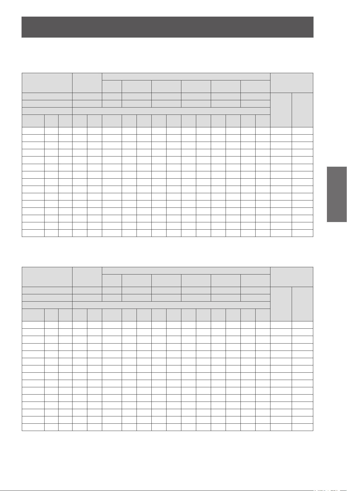
■Projection distance per projection lens (for PT-DX800E)
zWhen the screen aspect ratio is 4:3 (unit: m)
(All measurements below are approximate and may differ slightly from the actual measurements.)
zoom lens
zoom lens
Optional lens
Medium-focus
zoom lens
Optional lens
Medium-focus
zoom lens
Long-focus
zoom lens
Long-focus
zoom lens
Ultra long-focus
zoom lens
110.23
Ultra long-focus
zoom lens
100.05
120.12
Height position (H)
Standard
zoom lens/
ET-DLE150/
ET-DLE250/
ET-DLE350/
ET-DLE450
0–4.57
Height position (H)
Standard
zoom lens/
ET-DLE150/
ET-DLE250/
ET-DLE350/
ET-DLE450
-0.21–0.31 -0.16–0.31
-0.25–0.37 -0.19–0.37
-0.29–0.44 -0.23–0.44
-0.33–0.50 -0.26–0.50
-0.37–0.56 -0.29–0.56
-0.41–0.62 -0.32–0.62
-0.49–0.75 -0.39–0.75
-0.62–0.93 -0.49–0.93
-0.82–1.25 -0.65–1.25
-1.03–1.56 -0.81–1.56
-1.23–1.87 -0.97–1.87
-1.44–2.18 -1.13–2.18
-1.64–2.49 -1.30–2.49
-2.06–3.11 -1.62–3.11
-2.47–3.74 -1.94–3.74
Lens type
Projection lens Model No.
Throw ratio
Projection size Projection distance (L)
Screen size
(SD)
1.27 (50")
1.52 (60")
1.78 (70")
2.03 (80")
2.29 (90")
2.54 (100")
3.05 (120")
3.81 (150")
5.08 (200")
6.35 (250")
7.62 (300")
8.89 (350")
10.16 (400")
12.70 (500")
15.24 (600")
*1
Height
Width
(SH)
(SW)
0.762 1.016 1.78 2.51 0.81 0.81 1.01 1.34 1.97 2.36 3.78 3.71 5.68 5.53 8.91 0–0.38
0.914 1.219 2.15 3.03 0.98 0.98 1.22 1.62 2.37 2.85 4.55 4.48 6.84 6.69 10.75 0–0.46
1.067 1.422 2.52 3.55 1.15 1.15 1.43 1.90 2.77 3.34 5.32 5.25 8.01 7.86 12.60 0–0.53
1.219 1.626 2.90 4.06 1.32 1.32 1.64 2.18 3.18 3.83 6.09 6.02 9.17 9.02 14.44 0–0.61
1.372 1.829 3.26 4.58 1.49 1.49 1.86 2.46 3.58 4.32 6.86 6.79 10.33 10.19 16.28 0–0.69
1.524 2.032 3.63 5.10 1.66 1.66 2.07 2.74 3.98 4.80 7.63 7.56 11.50 11.35 18.12 0–0.76
1.829 2.438 4.37 6.13 2.01 2.00 2.49 3.30 4.79 5.78 9.18 9.10 13.82 13.68 21.81 0–0.91
2.286 3.048 5.48 7.68 2.52 2.51 3.12 4.14 6.00 7.24 11.49 11.41 17.31 17.18 27.33 0–1.14
3.048 4.064 7.33 10.16 3.38 3.36 4.18 5.54 8.02 9.69 15.34 15.26 23.13 23.00 36.54 0–1.52
3.810 5.080 9.18 12.85 – 4.21 5.23 6.94 10.03 12.13 19.20 19.11 28.94 28.83 45.76 0–1.91
4.572 6.096 11.03 15.43 – 5.07 6.29 8.33 12.05 14.57 23.06 22.96 34.76 34.66 54.97 0–2.29
5.334 7.112 12.88 18.02 – 5.92 7.34 9.73 14.07 17.01 26.91 26.81 40.57 40.48 64.18 0–2.67
6.096 8.128 14.73 20.60 – 6.77 8.40 11.13 16.08 19.45 30.77 30.65 46.39 46.31 73.39 0–3.05
7.620
10.160
9.144
12.192
Standard
zoom lens
–
2.2–3.0:1 1.0:1 1.0–1.2:1 1.6–2.4:1 2.9–4.6:1 4.5–6.9:1 6.8–10.8:1
Min. Max. Fixed Min. Max. Min. Max. Min. Max. Min. Max. Min. Max.
18.43 25.77 – 8.48 10.51 13.92 20.12 24.33 38.48 38.35 58.02 57.96 91.81 0–3.81
22.13 30.94 – 10.18 12.62 16.72 24.15 29.22 46.19 46.05 69.65 69.61
Fixed-
focus lens
ET-DLE055
Ultra short-
focus zoom lens
ET-DLE080 ET-DLE150 ET-DLE250 ET-DLE350 ET-DLE450
Short-focus
*1: The throw ratio is based on the value during projection onto a 2.03-m (80") screen size.
*2: When the xed-focus lens (ET-DLE055) is attached, the lens shift cannot be used, so the height position (H) will be SH/2.
zWhen the screen aspect ratio is 16:9 (unit: m)
(All measurements below are approximate and may differ slightly from the actual measurements.)
Lens type
Projection lens Model No.
Throw ratio
Projection size Projection distance (L)
Screen size
(SD)
1.27 (50")
1.52 (60")
1.78 (70")
2.03 (80")
2.29 (90")
2.54 (100")
3.05 (120")
3.81 (150")
5.08 (200")
6.35 (250")
7.62 (300")
8.89 (350")
10.16 (400")
12.70 (500")
15.24 (600")
*1
Height
Width
(SH)
(SW)
0.623 1.107 1.94 2.74 0.89 0.88 1.11 1.47 2.15 2.58 4.12 4.06 6.20 6.05 9.74
0.747 1.328 2.35 3.31 1.07 1.07 1.34 1.77 2.59 3.11 4.96 4.90 7.47 7.32 11.74
0.872 1.550 2.75 3.87 1.26 1.25 1.57 2.08 3.03 3.64 5.80 5.74 8.74 8.59 13.75
0.996 1.771 3.15 4.43 1.44 1.44 1.80 2.38 3.47 4.18 6.64 6.57 10.00 9.85 15.76
1.121 1.992 3.55 5.00 1.63 1.62 2.03 2.69 3.91 4.71 7.48 7.41 11.27 11.12 17.76
1.245 2.214 3.96 5.56 1.82 1.81 2.26 2.99 4.34 5.24 8.32 8.25 12.54 12.39 19.77
1.494 2.657 4.76 6.68 2.19 2.18 2.71 3.60 5.22 6.30 10.00 9.93 15.07 14.93 23.79
1.868 3.321 5.97 8.37 2.75 2.74 3.40 4.52 6.54 7.90 12.52 12.44 18.87 18.74 29.81
2.491 4.428 7.99 11.19 3.68 3.67 4.55 6.04 8.74 10.56 16.72 16.64 25.21 25.09 39.84
3.113 5.535 10.01 14.00 – 4.60 5.70 7.56 10.94 13.22 20.93 20.83 31.54 31.44 49.88
3.736 6.641 12.02 16.82 – 5.52 6.85 9.08 13.13 15.88 25.13 25.02 37.88 37.78 59.91
4.358 7.748 14.04 19.63 – 6.45 8.00 10.61 15.33 18.54 29.33 29.22 44.22 44.13 69.95
4.981 8.855 16.05 22.45 – 7.38 9.15 12.13 17.53 21.20 33.53 33.41 50.55 50.48 79.98
6.226
11.069
7.472
13.283
*1: The throw ratio is based on the value during projection onto a 2.03-m (80") screen size.
*2: When the xed-focus lens (ET-DLE055) is attached, the lens shift cannot be used, so the height position (H) will be SH/2.
Standard
zoom lens
–
1.8–2.5:1 0.8:1 0.8–1.0:1 1.3–2.0:1 2.4–3.8:1 3.7–5.6:1 5.6–8.9:1
Min. Max. Fixed Min. Max. Min. Max. Min. Max. Min. Max. Min. Max.
20.09 28.08 – 9.24 11.45 15.18 21.92 26.52 41.93 41.79 63.22 63.17
24.12 33.71 – 11.10 13.75 18.22 26.31 31.84 50.33 50.18 75.89 75.87
Fixed-
focus lens
ET-DLE055
Ultra short-
focus zoom lens
ET-DLE080 ET-DLE150 ET-DLE250 ET-DLE350 ET-DLE450
Short-focus
*2
ET-DLE080
0.08–0.38
0.09–0.46
0.11–0.53
0.12–0.61
0.14–0.69
0.15–0.76
0.18–0.91
0.23–1.14
0.31–1.52
0.38–1.91
0.46–2.29
0.53–2.67
0.61–3.05
0.76–3.81
0.91–4.57
*2
ET-DLE080
Getting Started
ENGLISH - 25
Setting up
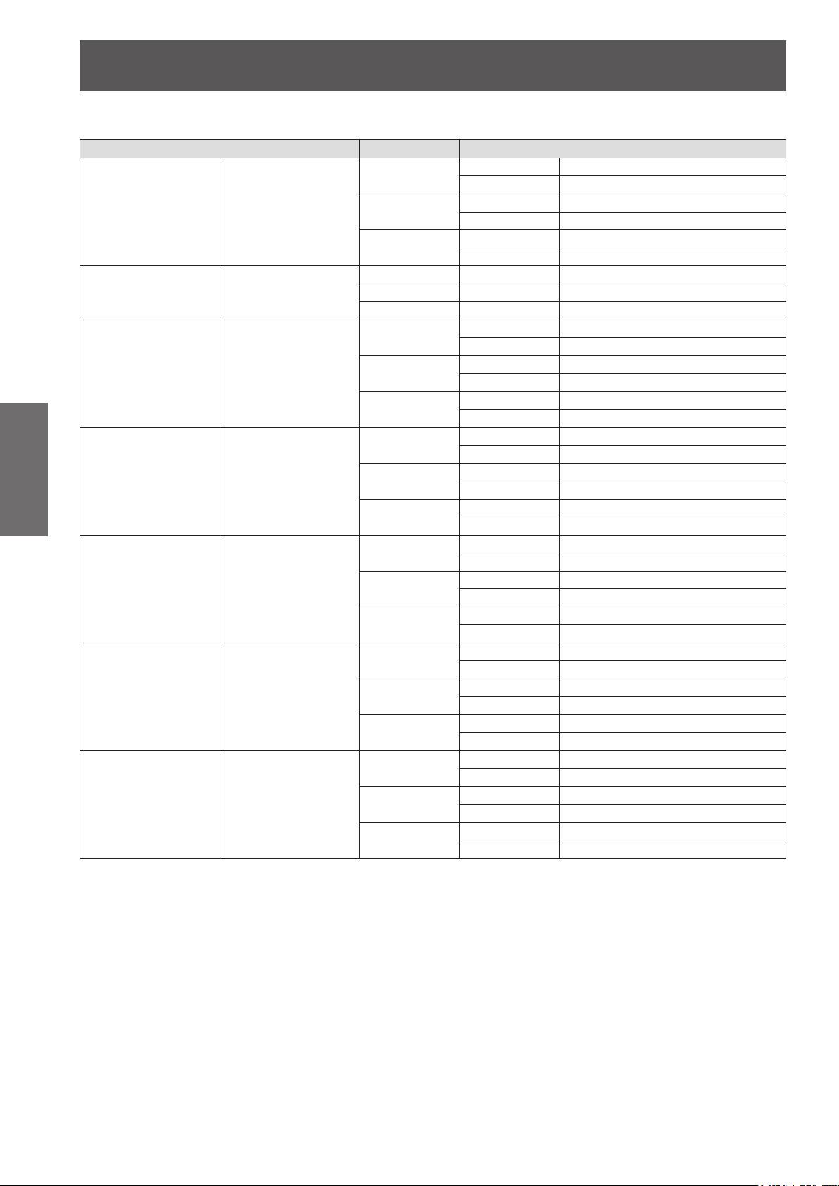
■ Projection distance calculation formula per projection lens (for PT-DW730E)
Standard zoom lens –
Fixed-focus lens Model No.: ET-DLE055
Ultra short-focus zoom lens
Getting Started
Short-focus zoom lens Model No.: ET-DLE150
Medium-focus zoom lens Model No.: ET-DLE250
Long-focus zoom lens Model No.: ET-DLE350
Ultra long-focus zoom lens
Lens type Aspect ratio Projection distance (L) formula
Min. (LW) L = 1.5669 x SD (m) – 0.0746
Max. (LT) L = 2.1850 x SD (m) – 0.0725
Min. (LW) L = 1.6102 x SD (m) – 0.0746
Max. (LT) L = 2.2480 x SD (m) – 0.0725
Min. (LW) L = 1.7717 x SD (m) – 0.0746
Max. (LT) L = 2.4724 x SD (m) – 0.0725
Min. (LW) L = 0.7205 x SD (m) – 0.0471
Max. (LT) L = 0.8937 x SD (m) – 0.0442
Min. (LW) L = 0.7402 x SD (m) – 0.0471
Max. (LT) L = 0.9173 x SD (m) – 0.0442
Min. (LW) L = 0.8150 x SD (m) – 0.0471
Max. (LT) L = 1.0118 x SD (m) – 0.0442
Min. (LW) L = 1.1811 x SD (m) – 0.
M
ax. (LT) L = 1.7047 x SD (m) – 0.0498
Min. (LW) L = 1.2165 x SD (m) – 0.0540
Max. (LT) L = 1.7520 x SD (m) – 0.0498
Min. (LW) L = 1.3386 x SD (m) – 0.0540
Max. (LT) L = 1.9291 x SD (m) – 0.0498
Min. (LW) L = 2.0630 x SD (m) – 0.0800
Max. (LT) L = 3.2598 x SD (m) – 0.0792
Min. (LW) L = 2.1220 x SD (m) – 0.0800
Max. (LT) L = 3.3504 x SD (m) – 0.0792
) L = 2.3386 x SD (m) – 0.0800
n. (LW
Mi
Max. (LT) L = 3.6929 x SD (m) – 0.0792
Min. (LW) L = 3.2559 x SD (m) – 0.1351
Max. (LT) L = 4.9173 x SD (m) – 0.1346
Min. (LW) L = 3.3465 x SD (m) – 0.1351
Max. (LT) L = 5.0551 x SD (m) – 0.1346
Min. (LW) L = 3.6850 x SD (m) – 0.1351
Max. (LT) L = 5.5669 x SD (m) – 0.1346
. (LW
Min
Max. (LT) L = 7.7913 x SD (m) – 0.2991
Min. (LW) L = 5.0630 x SD (m) – 0.3017
Max. (LT) L = 8.0079 x SD (m) – 0.2991
Min. (LW) L = 5.5787 x SD (m) – 0.3017
Max. (LT) L = 8.8189 x SD (m) – 0.2991
) L = 4.9291 x SD (m) – 0.3017
Model No.: ET-DLE080
Model No.: ET-DLE450
16:10
16:9
4:3
16:10 – L = 0.7244 x SD (m) – 0.0476
16:9 – L = 0.7441 x SD (m)
:3 – L = 0.8189 x SD (m) – 0.0476
4
16:10
16:9
4:3
16:10
16:9
4:3
16:10
16:9
4:3
16:10
16:9
4:3
16:10
16:9
4:3
– 0.0476
0540
26 - ENGLISH
Setting up
■ Projection distance calculation formula per projection lens (for PT-DX800E)
Lens type Aspect ratio Projection distance (L) formula
Min. (LW) L = 1.4567 x SD (m) – 0.0746
Max. (LT) L = 2.0354 x SD (m) – 0.0725
Min. (LW) L = 1.5866 x SD (m) – 0.0746
Max. (LT) L = 2.2165 x SD (m) – 0.0725
Min. (LW) L = 0.6693 x SD (m) – 0.0471
ax. (LT) L = 0.8307 x SD (m) – 0.0442
M
Min. (LW) L = 0.7323 x SD (m) – 0.0471
Max. (LT) L = 0.9055 x SD (m) – 0.0442
Min. (LW) L = 1.1024 x SD (m) – 0.0540
Max. (LT) L = 1.5866 x SD (m) – 0.0498
Min. (LW) L = 1.2008 x SD (m) – 0.0540
Max. (LT) L = 1.7283 x SD (m) – 0.0498
Min. (LW) L = 1.9213 x SD (m) –
ax. (LT) L = 3.0354 x SD (m) – 0.0792
M
Min. (LW) L = 2.0945 x SD (m) – 0.0800
Max. (LT) L = 3.3071 x SD (m) – 0.0792
Min. (LW) L = 3.0315 x SD (m) – 0.1351
Max. (LT) L = 4.5787 x SD (m) – 0.1346
Min. (LW) L = 3.3031 x SD (m) – 0.1351
Max. (LT) L = 4.9882 x SD (m) – 0.1346
Min. (LW) L = 4.5866 x SD (m) – 0.3017
ax. (LT) L = 7.2520 x SD (m) – 0.2991
M
Min. (LW) L = 5.0000 x SD (m) – 0.3017
Max. (LT) L = 7.9016 x SD (m) – 0.2991
0.0800
Standard zoom lens –
Fixed-focus lens Model No.: ET-DLE055
Ultra short-focus zoom lens
Short-focus zoom lens Model No.: ET-DLE150
Medium-focus zoom lens Model No.: ET-DLE250
Long-focus zoom lens Model No.: ET-DLE350
Ultra long-focus zoom lens
Model No.: ET-DLE080
Model No.: ET-DLE450
4:3
16:9
4:3 – L = 0.6732 x SD (m) – 0.0476
16:9 – L = 0.7323 x SD (m) – 0.0476
4:3
16:9
4:3
16:9
4:3
16:9
4:3
16:9
4:3
16:9
Getting Started
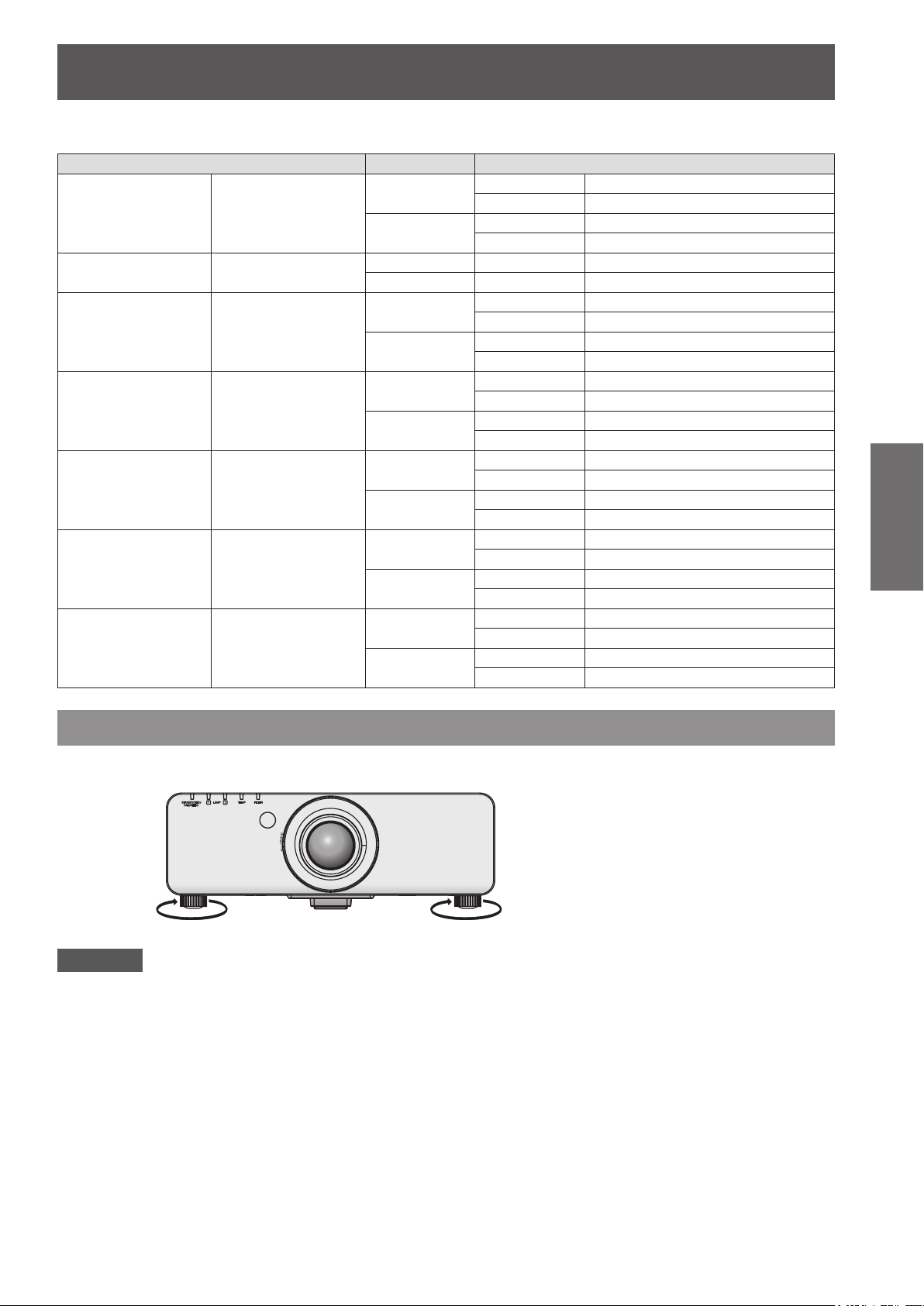
Adjustable feet
The adjustable feet can be extended by turning it as shown in the gure. It is retracted by turning it in the opposite
direction. (Projection angle can be adjusted vertically.)
Adjustable range
Front adjustable feet: 30 mm
Attention
zHeated air is blowing out from the air exhaust port while the lamp is on. Do not touch the air exhaust port
directly when adjusting the adjustable feet.
ENGLISH - 27
Removing/attaching the projection lens
Removing/attaching the projection lens
Perform the following steps when removing/attaching the standard zoom lens or the optional lens.
Move the lens to the home position before replacing or removing the lens. ( page 36)
Attention
zReplace the projection lens after turning off the power of the projector.
zDo not touch the lens signal receiver. Dust or dirt may cause defective contact.
zDo not touch the lens surface with your bare hands.
efore attaching the projection lens, remove the dust sponge attached to the projector and the lens cover
zB
attached to the projection lens.
zFor the ultra short-focus zoom lens (ET-DLE080), the procedure for removing/attaching the lens is different.
For details, refer to the instruction manual supplied with ET-DLE080.
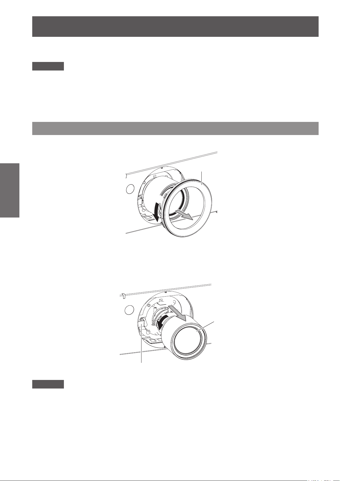
Removing the projection lens
1) Turn the projection lens cover counterclockwise and remove.
Getting Started
2) While pressing the lens release button, turn the projection lens counterclockwise all
the way, and remove the projection lens.
Projection lens cover
(i)
(ii)
(iii)
Projection lens
(ii)
Attention
zStore the removed lens where it will be free from vibration and impact.
28 - ENGLISH
(i)
Lens release button
Removing/attaching the projection lens
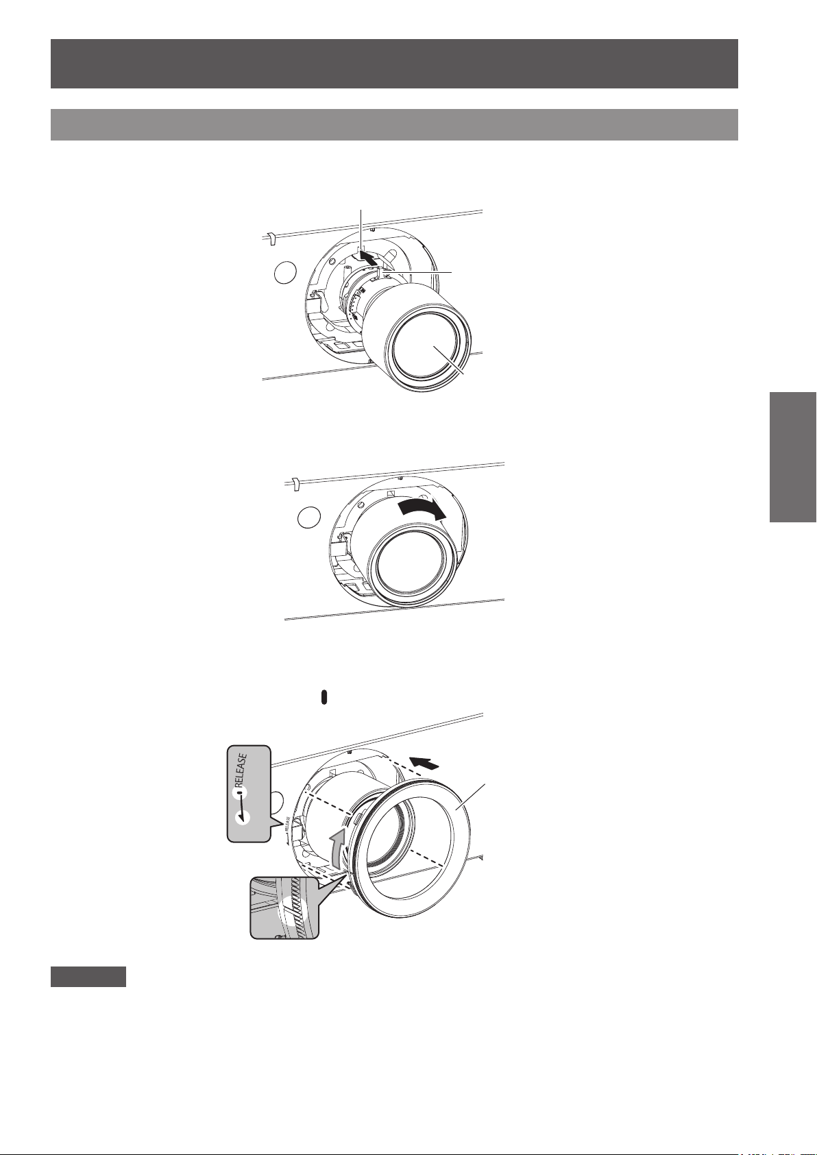
Groove
Attaching the projection lens
1) Remove the projection lens cover, align the guide of the projection lens to the guide
groove on the projector, and then insert the projection lens.
Guide
Projection lens
2) Turn the projection lens clockwise until it clicks.
3) Attach the projection lens cover aligning the marking (groove *1) to the tip of the
arrow on the projector (*2), and then turn and secure the projection lens cover until
the *1 groove aligns with the *3
*3
*2
marking.
(i)
Projection lens cover
(ii)
Getting Started
*1
Attention
zTurn the projection lens counterclockwise to conrm that it does not come out.
ENGLISH - 29
(1) (2)
(11) (15)
(17)(24)
Connections
Connections
Before connecting to the projector
zRead carefully the instruction manual for the device to be connected.
zTurning off the power switch of the devices before connecting cables.
zIf any connection cable is not supplied with the device, or if no optional cable is available for the connection of
the device, prepare a necessary system connection cable to suit the device.
zVideo signals containing too much jitter may cause the images on the screen to randomly wobble or wafture. In
this case, a time base corrector (TBC) must be connected.
zThe projector accepts the following signals: VIDEO, S-VIDEO, analog RGB (with TTL sync. Level) and digital
signal.
zSome computer models are not compatible with the projector.
zUse a compensator when you connect each of equipment to the projector using long cables. Otherwise the
image may not be output properly.
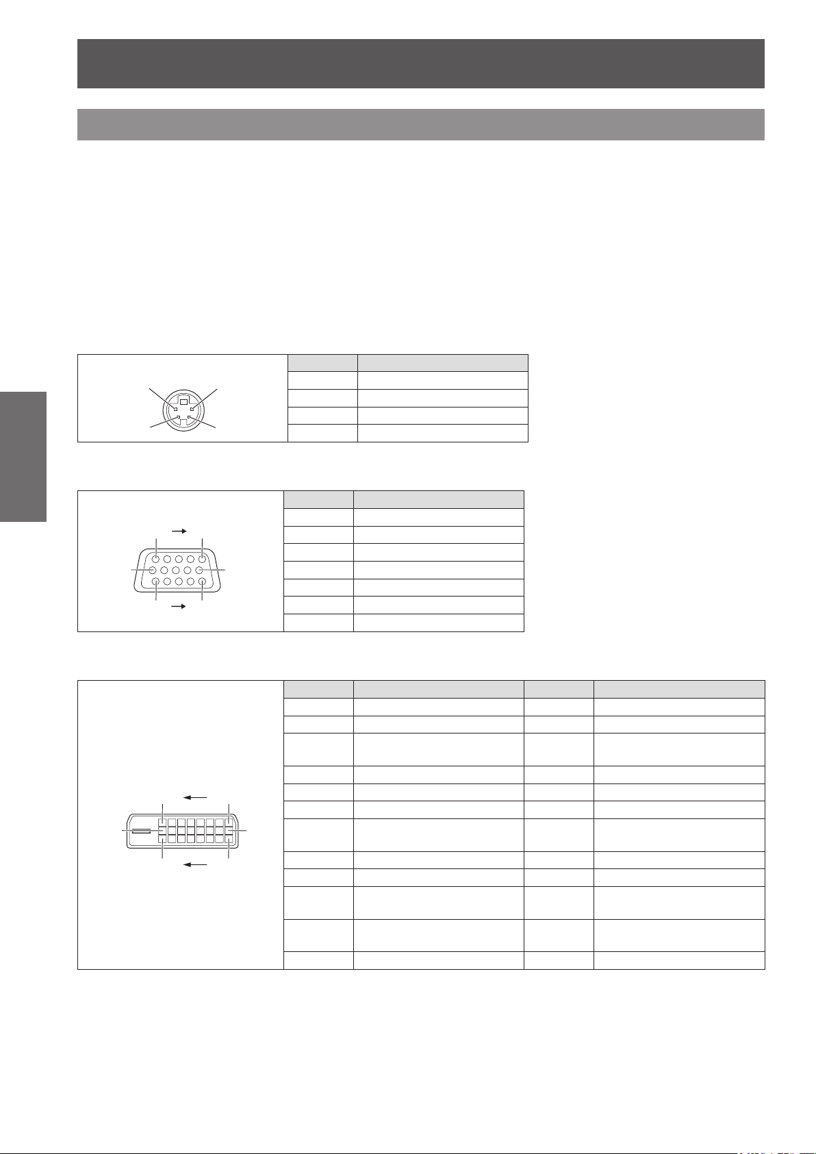
■<S-VIDEO IN> terminal pin assignments and signal names
Getting Started
Outside view Pin No. Signal names
(3) (4)
(1)
(2)
(3)
(4)
Ground (luminance signal)
Ground (color signal)
Luminance signal
Color signal
■<RGB 2 IN> terminal pin assignments and signal names
Outside view Pin No. Signal names
(6)
(1) (5)
(10)
(1)
(2)
(3)
(12)
(13)
(14)
(15)
R/PR
G/Y
B/PB
DDC data
SYNC/HD
VD
DDC clock
(4)
(5) - (8)
and
(9)
,
terminals.
are not used.
(10)
■<DVI-D IN> terminal pin assignments and signal names
Outside view Pin No. Signal name Pin No. Signal names
(16) (9)
(1)(8)
(1)
(2)
(3)
(4)
(5)
(6)
(7)
(8)
(9)
(10)
(11)
(12)
T.M.D.S data 2-
T.M.D.S data 2+
T.M.D.S data 2/4
shield
–
–
DDC clock
DDC data
–
T.M.D.S data 1-
T.M.D.S data 1+
T.M.D.S data 1/3
shield
–
(13)
(14)
(15)
(16)
(17)
(18)
(19)
(20)
(21)
(22)
(23)
(24)
(11)
, and
are GND
–
+5 V
GND
Hot plug detection
T.M.D.S data 0-
T.M.D.S data 0+
T.M.D.S data 0/5
shield
–
–
T.M.D.S clock
shield
T.M.D.S clock+
T.M.D.S clock-
30 - ENGLISH
 Loading...