

Page 1

Operating Instructions
Functional Manual
DLPTM Projector
Model No.
PT-DW640E
Commercial Use
PT-DW640EL
PT-DX610E
PT-DX610EL
Thank you for purchasing this Panasonic product.
■ This manual is common to all the models regardless of sufxes of the Model No.
zS: Silver model, the standard zoom lens supplied LS: Silver model, the lens sold separately
K: Black model, the standard zoom lens supplied LK: Black model, the lens sold separately
■ Before operating this product, please read the instructions carefully and save this manual
for future use.
■ Before using your projector, be sure to read “Read this rst!” (x pages 2 to 8).
ENGLISH
TQBJ0507
Page 2
Read this rst!
Read this rst!
WARNING: THIS APPARATUS MUST BE EARTHED.
WARNING: To prevent damage which may result in re or shock hazard, do not expose this appliance to rain
or moisture.
This device is not intended for use in the direct eld of view at visual display workplaces. To avoid
incommoding reexions at visual display workplaces this device must not be placed in the direct
eld of view.
The equipment is not intended for used at a video workstation in compliance BildscharbV.
The sound pressure level at the operator position is equal or less than 70 dB (A) according to ISO 7779.
WARNING:
1. Remove the plug from the mains socket when this unit is not in use for a prolonged period of time.
2. To prevent electric shock, do not remove cover. No user serviceable parts inside. Refer servicing to qualied
service personnel.
3. Do not remove the earthing pin on the mains plug. This apparatus is equipped with a three prong
earthingtype mains plug. This plug will only t an earthing-type mains socket. This is a safety feature. If you
are unable to insert the plug into the mains socket, contact an electrician. Do not defeat the purpose of the
earthing plug.
WARNING:
This is a class A product. In a domestic environment this product may cause radio interference in which case
the user may be required to take adequate measures.
CAUTION: To assure continued compliance, follow the attached installation instructions, which include
using the provided power cord and shielded interface cables when connecting to computer or
peripheral device. If you use serial port to connect PC for external control of projector, you must
use a commercial RS-232C serial interface cable with ferrite core. Any unauthorized changes or
modications to this equipment will void the user’s authority to operate.
Product information (for Turkey only)
EEE Yönetmeliğine Uygundur.
EEE Complies with Directive of Turkey.
Importer’s name and address within the European Union
Panasonic Marketing Europe GmbH
Panasonic Testing Center
Winsbergring 15, 22525 Hamburg, Germany
2 - ENGLISH
Page 3
Be sure to read “Read this rst!”
Read this rst!
IMPORTANT: THE MOULDED PLUG (U.K. only)
FOR YOUR SAFETY, PLEASE READ THE FOLLOWING TEXT CAREFULLY.
This appliance is supplied with a moulded three pin mains plug for your safety and convenience. A 13 amp fuse
is tted in this plug. Should the fuse need to be replaced, please ensure that the replacement fuse has a rating
of 13 amps and that it is approved by ASTA or BSI to BS1362.
Check for the ASTA mark
or the BSI mark on the body of the fuse.
If the plug contains a removable fuse cover, you must ensure that it is retted when the fuse is replaced. If you
lose the fuse cover, the plug must not be used until a replacement cover is obtained. A replacement fuse cover
can be purchased from an Authorised Service Center.
If the tted moulded plug is unsuitable for the mains socket in your home, then the fuse should be
removed and the plug cut off and disposed of safely.
There is a danger of severe electrical shock if the
cut off plug is inserted into any 13 amp socket.
If a new plug is to be tted, please observe the wiring code as shown below.
If in any doubt, please consult a qualied electrician.
WARNING: THIS APPLIANCE MUST BE EARTHED.
IMPORTANT: The wires in this mains lead are coloured in accordance with the following code:
Green - and - Yellow: Earth
Blue: Neutral
Brown: Live
As the colours of the wire in the mains lead of this appliance may not correspond with the coloured markings
dentifying the terminals in your plug, proceed as follows.
i
The wire which is coloured GREEN - AND - YELLOW must be connected to the terminal in the
plug which is marked with the letter E or by the Earth symbol
or coloured GREEN or GREEN -
AND - YELLOW.
The wire which is coloured BLUE must be connected to the terminal in the plug which is marked
with the letter N or coloured BLACK.
The wire which is coloured BROWN must be connected to the terminal in the plug which is marked
with the letter L or coloured RED.
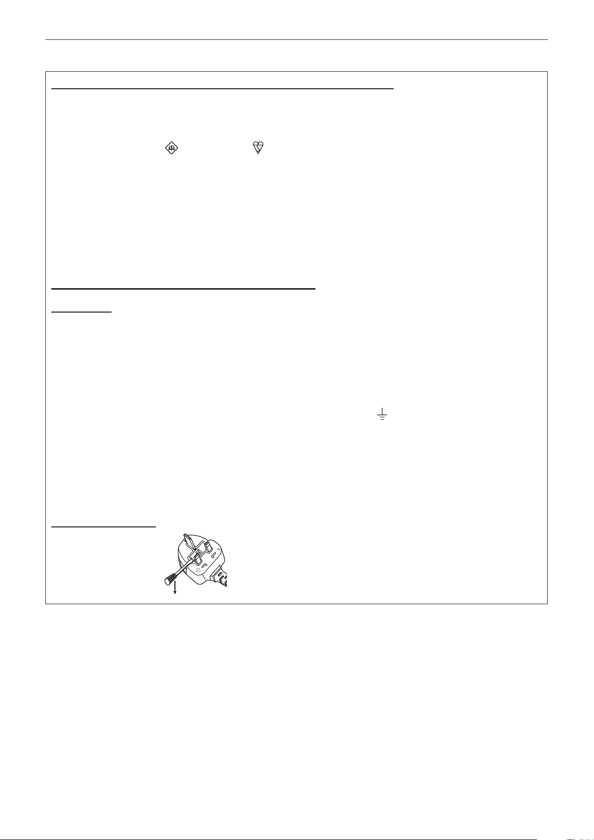
How to replace the fuse: Open the fuse compartment with a screwdriver and replace the fuse.
BS1363/A
N
13A250V
HE-8
L
ASA
ENGLISH - 3
Page 4

Read this rst!
WARNING:
POWER
The wall outlet or the circuit breaker shall be installed near the equipment and shall be easily accessible
when problems occur. If the following problems occur, cut off the power supply immediately.
Continued use of the projector in these conditions will result in re or electric shock.
zIf foreign objects or water get inside the projector, cut off the power supply.
zIf the projector is dropped or the cabinet is broken, cut off the power supply.
zIf you notice smoke, strange smells or noise coming from the projector, cut off the power supply.
Please contact an Authorized Service Center for repairs, and do not attempt to repair the projector yourself.
During a thunderstorm, do not touch the projector or the cable.
Electric shocks can result.
Do not do anything that might damage the power cord or the power plug.
If the power cord is used while damaged, electric shocks, short-circuits or re will result.
zDo not damage the power cord, make any modications to it, place it near any hot objects, bend it
excessively, twist it, pull it, place heavy objects on top of it or wrap it into a bundle.
Ask an Authorized Service Center to carry out any repairs to the power cord that might be necessary.
Completely insert the power plug into the wall outlet and the power connector into the projector terminal.
If the plug is not inserted correctly, electric shocks or overheating will result.
zDo not use plugs which are damaged or wall outlets which are coming loose from the wall.
Do not use anything other than the provided power cord.
Failure to observe this will result in re or electric shocks. Please note that if you do not use the provided power
cord to ground the device on the side of the outlet, this may result in electric shocks.
Clean the power plug regularly to prevent it from becoming covered in dust.
Failure to observe this will cause a re.
zIf dust builds up on the power plug, the resulting humidity can damage the insulation.
Pull the power plug out from the wall outlet and wipe it with a dry cloth regularly.
Do not handle the power plug and power connector with wet hands.
Failure to observe this will result in electric shocks.
Do not overload the wall outlet.
If the power supply is overloaded (ex., by using too many adapters), overheating may occur and re will result.
ON USE/INSTALLATION
Do not place the projector on soft materials such as carpets or sponge mats.
Doing so will cause the projector to overheat, which can cause burns, re or damage to the projector.
Do not set up the projector in humid or dusty places or in places where the projector may come into
contact with oily smoke or steam, ex. a bathroom.
Using the projector under such conditions will result in re, electric shocks or deterioration of components.
Deterioration of components (such as ceiling mount brackets) may cause the projector which is mounted on the
ceiling to fall down.
Do not install this projector in a place which is not strong enough to take the full weight of the projector
or on top of a surface which is sloped or unstable.
Failure to observe this will cause projector to fall down or tip over the projector, and severe injury or damage
could result.
4 - ENGLISH
Page 5

Read this rst!
WARNING:
Do not cover the air intake/exhaust ports or place anything within 500 mm (20") of them.
Doing so will cause the projector to overheat, which can cause re or damage to the projector.
zDo not place the projector in narrow, badly ventilated places.
zDo not place the projector on cloth or papers, as these materials could be drawn into the air inlet port.
Do not place your hands or other objects close to the air exhaust port.
Doing so will cause burns or damage your hands or other objects.
zHeated air comes out of the air exhaust port. Do not place your hands or face, or objects which cannot
withstand heat close to this port.
Do not look at or place your skin into the light emitted from the lens while the projector is being used.
Doing so can cause burns or loss of sight.
zStrong light is emitted from the projector’s lens. Do not look at or place your hands directly into this light.
zBe especially careful not to let young children look into the lens. In addition, turn off the power and
disconnect the power plug when you are away from the projector.
Never attempt to remodel or disassemble the projector.
High voltages can cause re or electric shocks.
zFor any inspection, adjustment and repair work, please contact an Authorized Service Center.
Do not project an image with the lens cover attached.
Doing so can cause re.
Do not allow metal objects, ammable objects, or liquids to enter inside of the projector. Do not allow
the projector to get wet.
Doing so may cause short circuits or overheating, and result in re, electric shock, or malfunction of the
projector.
zDo not place containers of liquid or metal objects near the projector.
zIf liquid enters inside of the projector, consult your dealer.
zParticular attention must be paid to children.
Use the ceiling mount bracket specied by Panasonic.
Using the ceiling mount bracket other than the specied one will result in falling accidents.
zAttach the supplied safety cable to the ceiling mount bracket to prevent the projector from falling down.
Installation work (such as ceiling mount bracket) should only be carried out by a qualied technician.
If installation is not carried out and secured correctly it can cause injury or accidents, such as electric shocks.
zDo not use anything other than an authorized ceiling mount bracket.
zBe sure to use the provided accessory wire with an eye bolt as an extra safety measure to prevent the
projector from falling down. (Install in a different location to the ceiling mount bracket.)
ENGLISH - 5
Page 6

Read this rst!
WARNING:
ACCESSORIES
Do not use or handle the batteries improperly, and refer to the following.
Failure to observe this will cause burns, batteries to leak, overheat, explode or catch re.
zUse AA/R6 batteries.
zDo not use unspecied batteries.
zDo not use chargeable batteries.
zDo not disassemble dry cell batteries.
zDo not heat the batteries or place them into water or re.
zDo not allow the + and – terminals of the batteries to come into contact with metallic objects such as
necklaces or hairpins.
zDo not store or carry batteries together with metallic objects.
zStore the batteries in a plastic bag and keep them away from metallic objects.
zMake sure the polarities (+ and –) are correct when inserting the batteries.
zDo not use a new battery together with an old battery or mix different types of batteries.
zDo not use batteries with the outer cover peeling away or removed.
If the battery uid leaks, do not touch it with bare hands, and take the following measures if necessary.
zBattery uid on your skin or clothing could result in skin inammation or injury.
Rinse with clean water and seek medical advice immediately.
zBattery uid coming in contact with your eyes could result in loss of sight.
In this case, do not rub your eyes. Rinse with clean water and seek medical advice immediately.
Do not disassemble the lamp unit.
Doing so can cause electric shocks, burns, or injury.
Lamp replacement
The lamp has high internal pressure. If improperly handled, an explosion and severe injury or accidents will
result.
zThe lamp can easily explode if struck against hard objects or dropped.
zBefore replacing the lamp, be sure to turn the power off and to disconnect the power plug from the wall
outlet.
Electric shocks or explosions can result if this is not done.
zWhen replacing the lamp, turn the power off and allow it to cool for at least one hour before handling it
otherwise it can cause burns.
Do not use the supplied power cord with devices other than this projector.
zUsing the supplied power cord with devices other than this projector may cause short circuits or
overheating, and result in electric shock or re.
Remove the depleted batteries from the remote control promptly.
zLeaving them in the unit may result in uid leakage, overheating, or explosion of the batteries.
CAUTION:
POWER
When disconnecting the power cord, be sure to hold the power plug and power connector.
If the power cord itself is pulled, the lead will become damaged, and re, short-circuits or serious electric
shocks will result.
When not using the projector for an extended period of time, disconnect the power plug from the wall
outlet.
Failure to do so may result in re or electric shock.
Disconnect the power plug from the wall outlet before carrying out any cleaning and replacing the unit.
Failure to do so may result in electric shock.
6 - ENGLISH
Page 7

Read this rst!
CAUTION:
ON USE/INSTALLATION
Do not place heavy objects on top of the projector.
Failure to observe this will cause the projector to become unbalanced and fall, which could result in damage or
injury. The projector will be damaged or deformed.
Do not put your weight on this projector.
You could fall or the projector could break, and injury will result.
zBe especially careful not to let young children stand or sit on the projector.
Do not place the projector in extremely hot locations.
Doing so will cause the outer casing or internal components to deteriorate, or result in re.
zTake particular care in locations exposed to direct sunlight or near stoves.
Do not place your hands in the openings beside the optical lens, while shifting the lens.
Failure to observe this could cause injury.
Do not stand in front of the lens while the projector is being used.
Doing so can cause damage and burns to clothing.
zStrong light is emitted from the projector’s lens.
Do not place objects in front of the lens while the projector is being used.
Doing so can cause damage to the object and can cause the set to malfunction.
zStrong light is emitted from the projector’s lens.
Always disconnect all cables before moving the projector.
Moving the projector with cables still attached can damage the cables, which will cause re or electric shocks to
occur.
ACCESSORIES
Do not use the old lamp unit.
If used it could cause lamp explosion.
If the lamp has broken, ventilate the room immediately. Do not touch or bring your face close to the
broken pieces.
Failure to observe this will cause the user to absorb the gas which was released when the lamp broke and
which contains nearly the same amount of mercury as uorescent lamps, and the broken pieces will cause
injury.
zIf you believe that you have absorbed the gas or that the gas has got into your eyes or mouth, seek medical
advice immediately.
zAsk your dealer about replacing the lamp unit and check the inside of the projector.
Do not attach the air lter unit while it is wet.
Doing so may result in electric shock or malfunctions.
zAfter you clean the air lter units, dry them thoroughly before reattaching them.
Do not touch the fan with your ngers or any other parts of your body when changing the lamp unit.
Doing so can cause injury.
Ask your dealer about cleaning inside the projector once a year.
Continuous use while dust is accumulated inside the projector may result in re.
zFor cleaning fee, ask your dealer.
When not using the projector for an extended period of time, remove the batteries from the remote
control.
Failure to observe this will cause the batteries to leak, overheat, catch re or explode, which may result in re
or contamination of surrounding area.
ENGLISH - 7
Page 8

To remove the battery
Remote Control Battery
Read this rst!
1. Press the guide and lift the cover.
(ii)
(i)
2. Remove the batteries.
8 - ENGLISH
Page 9

Trademarks
rr
• Microsoft®, Windows®, Windows Vista®, and Internet Explorer® are the registered trademarks or trademarks of
Microsoft Corporation in the United States and/or other countries.
• Mac, Mac OS, Mac OSX, and Safari are the trademarks of Apple Inc. registered in the United States and
other countries.
• PJLinkTM is a trademark or pending trademark in Japan, the United States, and other countries and regions.
• HDMI, the HDMI logo and High-Denition Multimedia Interface are trademarks or registered trademarks of
HDMI Licensing LLC.
• VGA and XGA are trademarks of International Business Machines Corporation.
• SVGA is a registered trademark of the Video Electronics Standards Association.
• RoomView, Crestron RoomView, Crestron Connected, and Fusion RV are trademarks of Crestron Electronics,
Inc.
• The font used in the on-screen displays is a Ricoh bitmap font, which is manufactured and sold by Ricoh
Company, Ltd.
• Adobe Flash Player is either a trademark or registered trademark of Adobe Systems Incorporated in the
United States and/or other countries.
• Other names, company names or product names used in these operating instructions are the trademarks or
registered trademarks of their respective holders.
Please note that the operating instructions do not include the ® and TM symbols.
Illustrations in these operating instructions
rr
• Note that illustrations of the projector and screens may differ from the ones you actually see.
Page references
rr
• In these instructions, references to pages are indicated as: ( page 00).
Term
rr
• In these instructions, the “Wireless/wired remote control unit” accessories are referred to as the “Remote
control”.
ENGLISH - 9
Page 10

Features of the Projector
High luminance & High color
reproducibility
▶The unique optical and lamp drive systems
achieve a high luminance and high color
reproducibility while saving power.
Easy setup and improved
serviceability
▶Extensive lineup of optional lenses allow
more exible setup of the projector.
Improved cost performance in
maintenance fee
Quick Steps
For details, see the corresponding pages.
1. Set up the projector.
(x page 26)
c
2. Attach the projection lens.
(x page 35)
c
3. Connect with other devices.
(x page 37)
c
4. Connect the power cord.
(x page 41)
▶The long life lter reduces maintenance
costs.
c
5. Switch on the projector.
(x page 42)
c
6. Make initial settings.
(x page 19)
*
c
7. Select the input signal.
(x page 45)
c
8. Adjust the image.
(x page 45)
10 - ENGLISH
* These are the steps to be taken when you switch on the power for the
rst time after purchasing the projector.
Page 11

Contents
Contents
Read this rst! ............................................2
Chapter 1 Preparation
Precautions for use ................................................. 14
Cautions when transporting .................................. 14
Cautions when installing ....................................... 14
Security ................................................................ 15
Disposal ................................................................ 16
Cautions on use ................................................... 16
Software information regarding this product ......... 16
Accessories .......................................................... 17
Optional accessories ............................................ 18
Start-up display ....................................................... 19
Initial setting (display language) ........................... 19
Initial setting (projector setup) .............................. 19
About your projector ............................................... 20
Remote control ..................................................... 20
Projector body ...................................................... 21
Using the remote control ........................................ 23
Inserting and removing the batteries .................... 23
Setting Remote control ID numbers ..................... 23
Connecting to the projector with a cable .............. 24
Chapter 2 Getting Started
Setting up ................................................................. 26
Projection method ................................................ 26
Parts for ceiling mount (optional) .......................... 26
Screen size and throw distance ........................... 27
Adjusting adjustable feet ...................................... 34
Removing/attaching the projection lens ............... 35
Removing the projection lens ............................... 35
Attaching the projection lens ................................ 35
Connections ............................................................. 37
Before connecting to the projector ....................... 37
Connecting example: AV equipment .................... 38
Connecting example: Computers ......................... 38
Chapter 3 Basic Operation
Switching on/off the projector ................................ 41
Connecting the power cord .................................. 41
Power indicator ..................................................... 42
Switching on the projector .................................... 42
Making adjustments and selections ..................... 43
Switching off the projector .................................... 43
Direct power off function ....................................... 44
Be sure to read “Read this rst!”. (x pages 2 to 8)
Projecting ................................................................. 45
Selecting the input signal ..................................... 45
Adjusting the focus, zoom, and shift ..................... 45
Moving the lens to the home position ................... 46
Adjustment range by the lens position shift
(optical shift) ...................................................... 46
Remote control operation ....................................... 47
Using the shutter function ..................................... 47
Using the on-screen display function ................... 47
Switching the input ............................................... 48
Using the status function ...................................... 48
Using the automatic setup function ...................... 48
Using the function button ...................................... 49
Displaying the internal test pattern ....................... 49
Changing the picture aspect ratio ......................... 49
Chapter 4 Settings
Menu navigation ...................................................... 51
Navigating through the menu ............................... 51
Main menu ............................................................ 52
Sub-menu ............................................................. 52
[PICTURE] menu ...................................................... 55
[PICTURE MODE] ................................................ 55
[CONTRAST] ........................................................ 55
[BRIGHTNESS] .................................................... 55
[COLOR] ............................................................... 56
[TINT] ................................................................... 56
[COLOR TEMPERATURE] ................................... 56
[WHITE GAIN] ...................................................... 57
[SYSTEM DAYLIGHT VIEW] ................................ 57
[SHARPNESS] ..................................................... 58
[NOISE REDUCTION] .......................................... 58
[AI] ........................................................................ 58
[SYSTEM SELECTOR] ........................................ 59
[POSITION] menu .................................................... 60
[SHIFT] ................................................................. 60
[ASPECT] ............................................................. 60
[ZOOM] ................................................................. 61
[CLOCK PHASE] .................................................. 62
[KEYSTONE] ........................................................ 63
[ADVANCED MENU] menu ...................................... 64
[DIGITAL CINEMA REALITY] ............................... 64
[BLANKING] ......................................................... 64
[INPUT RESOLUTION] ........................................ 65
[CLAMP POSITION] ............................................. 65
[EDGE BLENDING] .............................................. 65
[RASTER POSITION] ........................................... 66
ENGLISH - 11
Page 12

Contents
[DISPLAY LANGUAGE] menu ................................. 67
Changing the display language ............................ 67
[DISPLAY OPTION] menu ........................................ 68
[COLOR MATCHING] ........................................... 68
[COLOR CORRECTION] ..................................... 69
[CONTRAST MODE] ............................................ 69
[SCREEN SETTING] ............................................ 69
[AUTO SIGNAL] ................................................... 70
[AUTO SETUP]..................................................... 70
[RGB IN] ............................................................... 70
[DVI-D IN] ............................................................. 70
[HDMI IN] .............................................................. 71
[ON-SCREEN DISPLAY] ...................................... 71
[BACK COLOR] .................................................... 72
[STARTUP LOGO] ................................................ 72
[SHUTTER SETTING] .......................................... 73
[FREEZE] ............................................................. 73
[SIDE BY SIDE] (PT-DW640E only) ..................... 73
[CUT OFF] ............................................................ 74
[PROJECTOR SETUP] menu .................................. 75
[PROJECTOR ID] ................................................. 75
[PROJECTION METHOD] .................................... 75
[COOLING CONDITION] ...................................... 76
[HIGH ALTITUDE MODE] ..................................... 76
[LAMP SELECT] ................................................... 76
[LAMP RELAY] ..................................................... 77
[LAMP POWER] ................................................... 77
[STANDBY MODE] ............................................... 78
[SCHEDULE] ........................................................ 78
[STARTUP INPUT SELECT] ................................ 79
[RS-232C] ............................................................. 80
[REMOTE2 MODE] .............................................. 81
[STATUS] .............................................................. 81
[NO SIGNAL SHUT-OFF] ..................................... 82
[FUNCTION BUTTON] ......................................... 82
[DATE AND TIME] ................................................ 83
[SAVE ALL USER DATA] ...................................... 83
[LOAD ALL USER DATA] ..................................... 84
[INITIALIZE] .......................................................... 84
[SERVICE PASSWORD] ...................................... 84
[TEST PATTERN] menu ........................................... 85
[TEST PATTERN] ................................................. 85
[SIGNAL LIST] menu ............................................... 86
Registering a signal to the list .............................. 86
Renaming the registered data .............................. 86
Deleting the registered data ................................. 86
Protecting the registered data .............................. 87
Expanding signal lock-in range ............................ 87
Managing the sub memory list ............................. 87
[SECURITY] menu ................................................... 89
[SECURITY PASSWORD] .................................... 89
[SECURITY PASSWORD CHANGE] ................... 89
[DISPLAY SETTING] ............................................ 89
[TEXT CHANGE] .................................................. 90
[MENU LOCK] ...................................................... 90
[MENU LOCK PASSWORD] ................................ 90
[CONTROL DEVICE SETUP] ............................... 90
[NETWORK] menu ................................................... 92
[NETWORK SETUP] ............................................ 92
[NETWORK CONTROL] ...................................... 92
[NETWORK STATUS] .......................................... 93
Network connections ............................................ 93
Accessing from the Web browser ......................... 94
Chapter 5 Maintenance
Lamp/Temperature/Filter indicators .................... 110
Managing the indicated problems .......................110
Maintenance/replacement..................................... 112
Before maintaining/replacing the unit ..................112
Maintenance ........................................................112
Replacing the unit ................................................113
Troubleshooting .................................................... 116
Chapter 6 Appendix
Technical information ........................................... 11 8
PJLink protocol ....................................................118
Control commands via LAN .................................119
<SERIAL IN>/<SERIAL OUT> terminal .............. 121
<REMOTE 2 IN> terminal .................................. 124
Two window display combination list (PT-
DW640E only) ................................................. 125
Menu lock password ........................................... 125
List of compatible signals ................................... 125
Specications ........................................................ 127
Dimensions ............................................................ 129
Ceiling mount bracket safeguards....................... 130
Index ....................................................................... 131
12 - ENGLISH
Page 13

Chapter 1
This chapter describes things you need to know or check before using the projector.
Preparation
ENGLISH - 13
Page 14

Chapter 1 Preparation — Precautions for use
Precautions for use
Cautions when transporting
The projection lens is susceptible to effects from vibration or impact. Make sure to remove the projection lens when transporting.
rf
Also, use a protection cover or the like to prevent dust from affecting the projection lens or the set.
When transporting the projector, hold it securely by its bottom and avoid excessive vibration and impacts. They may damage the internal
rf
parts and result in malfunctions.
Do not transport the projector with the adjustable feet extended. Doing so may damage the adjustable feet.
rf
Cautions when installing
Always attach the projection lens cover after attaching the projection lens.
rr
If the cover is not attached, dust will accumulate inside and may cause malfunctions.
Do not set up the projector outdoors.
rr
The projector is designed for indoor use only.
Do not set up the projector in the following locations.
rr
Places where vibration and impacts occur such as in a car or vehicle: Doing so may cause damage to internal parts or malfunction.
rf
Near the exhaust of an air conditioner: Depending on the conditions of use, the screen may uctuate in rare cases due to the hot air from
rf
the air exhaust port or the heated or cooled air. Make sure that the exhaust from the projector or other equipment, or the air from the air
conditioner does not blow toward the front of the projector.
Near lights (studio lamps, etc.) and other locations of great temperature uctuation (“Operating environment” (x page 128)): Doing so may
rf
shorten the life of the lamp or result in deformation of the outer case and malfunctions.
Near high-voltage power lines or near motors: Doing so may interfere with the operation of the projector.
rf
Place where there is high-power laser equipment: Directing a laser beam onto the lens surface causes damage to the DLP chips.
rf
Be sure to ask a specialized technician or your dealer when installing the product to a ceiling.
rr
If the product is to be installed hanging from the ceiling, purchase an optional Ceiling Mount Attachment.
Model No.: ET-PKD56H (for high ceilings), ET-PKD55S (for low ceilings)
Lens focus
rr
The high clarity projection lens is thermally affected by the light from the light source, making the focus unstable in the period just after
switching on the power. Wait at least 30 minutes with the image projected before adjusting the lens focus.
Make sure to set [HIGH ALTITUDE MODE] to [ON] when using the projector at elevations of
rr
1 400 m (4 593 ft) or higher and lower than 2 700 m (8 858 ft) above sea level.
Doing so may shorten the life of the internal parts and result in malfunctions.
Make sure to set [HIGH ALTITUDE MODE] to [OFF] when using the projector at elevations
rr
lower than 1 400 m (4 593 ft) above sea level.
Doing so may shorten the life of the internal parts and result in malfunctions.
Do not install the projector at elevations of 2 700 m (8 858 ft) or higher above sea level.
rr
Doing so may shorten the life of the internal parts and result in malfunctions.
Do not use the projector tilted to the right or left
rr
Using the projector at a vertical angle that exceeds 15° may reduce product life or result in malfunction.
When installing and using the projector at an angle that exceeds 30° vertically, set [COOLING
rr
CONDITION] (x page 76).
Failure to observe this will result in malfunctions or shorten the life of the lamp or other components.
Cautions when setting up the projector
rr
To install and use the projector via a method that does not use the adjustable feet in a oor standing installation, x the projector using the
rf
ve screw holes for ceiling mounting (Fig. 1).
(Screw diameter: M6, tapping depth inside the set: 12 mm (15/32"), torque: 4 ± 0.5 N·m)
14 - ENGLISH
Page 15

Chapter 1 Preparation — Precautions for use
6FUHZKROHVIRUFHLOLQJPRXQW0
PPRUORQJHU PPRUORQJHU PPRUORQJHU
Use the adjustable feet only for the oor standing installation and for adjusting the angle. Using it for other purposes may damage the set.
rf
$GMXVWDEOHIHHW
)LJ7KHSRVLWLRQVRIVFUHZKROHVIRUFHLOLQJPRXQWDQGDGMXVWDEOHIHHW
Do not stack projectors on top of each other.
rf
Do not hold the projector by the top surface.
rf
Do not use the projector tilted at an angle that exceeds ± 15° from the horizontal plane.
rf
Do not block the ventilation ports (intake and exhaust) of the projector.
rf
Prevent hot and cool air from the air conditioning system from blowing directly to the ventilation ports (intake and exhaust) of the projector.
rf
PPRUORQJHU
Do not install the projector in a conned space.
rf
When it is necessary to install the projector in a conned space, install the air conditioning or ventilation separately. Exhaust heat may
accumulate when the ventilation is not enough, triggering the protection circuit of the projector.
Make a clearance of at least 20 mm (0.8") between the projector bottom and setting surface by inserting spacers (metallic) etc. between
rf
them.
Security
When using this product, take safety measures against the following incidents.
Personal information being leaked via this product
rf
Unauthorized operation of this product by a malicious third party
rf
Interfering or stopping of this product by a malicious third party
rf
Take sufcient security measures. (x pages 89, 104)
Make your password difcult to guess as much as possible.
rf
Change your password periodically.
rf
Panasonic Corporation or its afliate companies will never ask for your password directly. Do not divulge your password in case you receive
rf
such inquiries.
The connecting network must be secured by a rewall, etc.
rf
Set a password for the web control and restrict the users who can log in.
rf
ENGLISH - 15
Page 16

Chapter 1 Preparation — Precautions for use
Disposal
To dispose of the product, ask your local authorities or dealer for correct methods of disposal.
The lamp contains mercury. When disposing of used lamp units, contact your local authorities or dealer for correct methods of disposal.
Cautions on use
To get a good picture quality
rr
In order to view a beautiful image in higher contrast, prepare an appropriate environment. Draw curtains or blinds over windows and turn off
any lights near the screen to prevent outside light or light from indoor lamps from shining onto the screen.
Do not touch the surface of the projection lens with your bare hands.
rr
If the surface of the projection lens becomes dirty from ngerprints or anything else, this will be magnied and projected onto the screen.
Please put the lens cover (accessory) on the projector when you do not use it.
DLP chips
rr
The DLP chips are precision-made. Note that in rare cases, pixels of high precision could be missing or always lit. Note that such
rf
phenomena does not indicate malfunction. This is not a malfunction.
Directing a high-power laser beam onto the lens surface can damage the DLP chips.
rf
Do not move the projector while it is operating or subject it to vibration or impact.
rr
Doing so may shorten the service life of its internal components.
Lamp
rr
The luminous source of the projector is a high-pressure mercury lamp.
A high-pressure mercury lamp has the following characteristics.
The luminance of the lamp will decrease by duration of usage.
rf
The lamp may burst with a loud sound or have its service life shortened because of shock, chipping, or degradation due to cumulative
rf
operating time.
The lamp life varies greatly depending on individual differences and usage conditions. In particular, frequently switching the power on/off
rf
accelerates lamp deterioration and greatly affects lamp life.
Continuous use for one week or longer accelerates lamp deterioration. Lamp relay function (x page 77) can be used to reduce
rf
deterioration caused by continuous use.
In rare cases, the lamps burst shortly after projection starts.
rf
The risk of bursting increases when the lamp is used beyond its replacement cycle. Make sure to replace the lamp unit regularly.
rf
(“When to replace the lamp unit” (x page 114), “Replacing the lamp unit” (x page 114))
If the lamp bursts, gas contained inside of the lamp is released in a form of smoke.
rf
It is recommended that you store replacement lamp units for contingency.
rf
About connections to computer or peripheral device
rr
To assure continued compliance, follow the attached installation instructions, which include using the provided power cord and shielded
rf
interface cables when connecting to computer or peripheral device.
Use a commercial DVI-D cable with a ferrite core.
rf
Software information regarding this product
© Panasonic Corporation 2012
This product incorporates the following software.
(1) The software which is developed independently by or for Panasonic Corporation
(2)The software which is licensed under the GNU GENERAL PUBLIC LICENSE
(3)The software which is licensed under the GNU LESSER GENERAL PUBLIC LICENSE
For the license conditions of software categorized as (2) and (3), refer to the provisions of the Software license (GNU GENERAL PUBLIC
LICENSE and GNU LESSER GENERAL PUBLIC LICENSE) in the supplied CD-ROM. (Those provisions are written in the original (English)
because they have been stipulated by third parties.)
If you have any questions regarding the software, contact (sav.pj.gpl.pavc@ml.jp.panasonic.com) by E-mail.
16 - ENGLISH
Page 17
Chapter 1 Preparation — Precautions for use
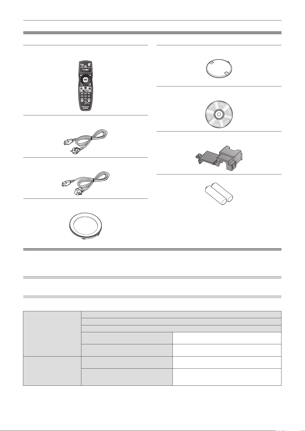
Accessories
Make sure that the following accessories are provided with your projector. Numbers enclosed in < > show the number of accessories.
Wireless/wired remote control unit <1>
(N2QAYB000784)
Power cord <1>
(K2CM3FZ00003)
Power cord <1>
(K2CT3FZ00003)
Lens cover <1>
(TKKL5244)
(for models with attached lenses only)
CD-ROM <1>
(TXFQB02VLH4)
Power cord secure lock <1>
(TTRA0183)
AA/R6 battery <2>
Projection lens cover <1>
(TKPB35101)
Attention
After unpacking the projector, discard the power cord cap and packaging material properly.
rf
For missing accessories, consult your dealer.
rf
Store small parts in an appropriate manner, and keep them away from small children.
rf
Note
The model numbers of accessories and optional components are subject to change without notice.
rf
Contents of the supplied CD-ROM
The contents of the supplied CD-ROM are as follows.
Instruction/list (PDF) Operating Instructions - Functional Manual
Multi Projector Monitoring & Control Software Operation Manual
Logo Transfer Software Operating Manual
List of Compatible Projector Models This is a list of projectors that are compatible with the
software contained in the CD-ROM and their restrictions.
Software license (GNU GENERAL PUBLIC LICENSE, GNU LESSER
GENERAL PUBLIC LICENSE)
Software Multi Projector Monitoring & Control Software
(Windows)
Logo Transfer Software (Windows) This software allows you to create original images, such
This software allows you to monitor and control multiple
projectors connected to the LAN.
as company logos to be displayed when projection starts,
and transfer them to the projector.
(For remote control unit)
ENGLISH - 17
Page 18

Chapter 1 Preparation — Precautions for use
Optional accessories
Optional accessories (product name) Model No.
ET-DLE055 (xed-focus lens), ET-DLE080 (ultra short-focus zoom lens), ET-DLE150 (short-
Projection lens
Ceiling mount bracket ET-PKD56H (for high ceilings), ET-PKD55S (for low ceilings)
Replacement lamp unit ET-LAD60A (1 pc), ET-LAD60AW (2 pcs)
Replacement lter unit ET-EMF300
focus zoom lens), ET-DLE250 (medium-focus zoom lens), ET-DLE350 (long-focus zoom lens),
ET-DLE450 (ultra long-focus zoom lens)
18 - ENGLISH
Page 19
Chapter 1 Preparation — Start-up display
Start-up display
The initial setting screen is displayed when the projector is switched on for the rst time after purchase as well as when [INITIALIZE] – [ALL
USER DATA] (x page 84) is executed. Set them in accordance with circumstances.
In other occasions, you can change the settings by menu operations.
Note
When the projector is used for the rst time, you may be required to adjust the focus, zoom, and shift to display the menu screen clearly.
rf
Refer to “Adjusting the focus, zoom, and shift” (x page 45) for details.
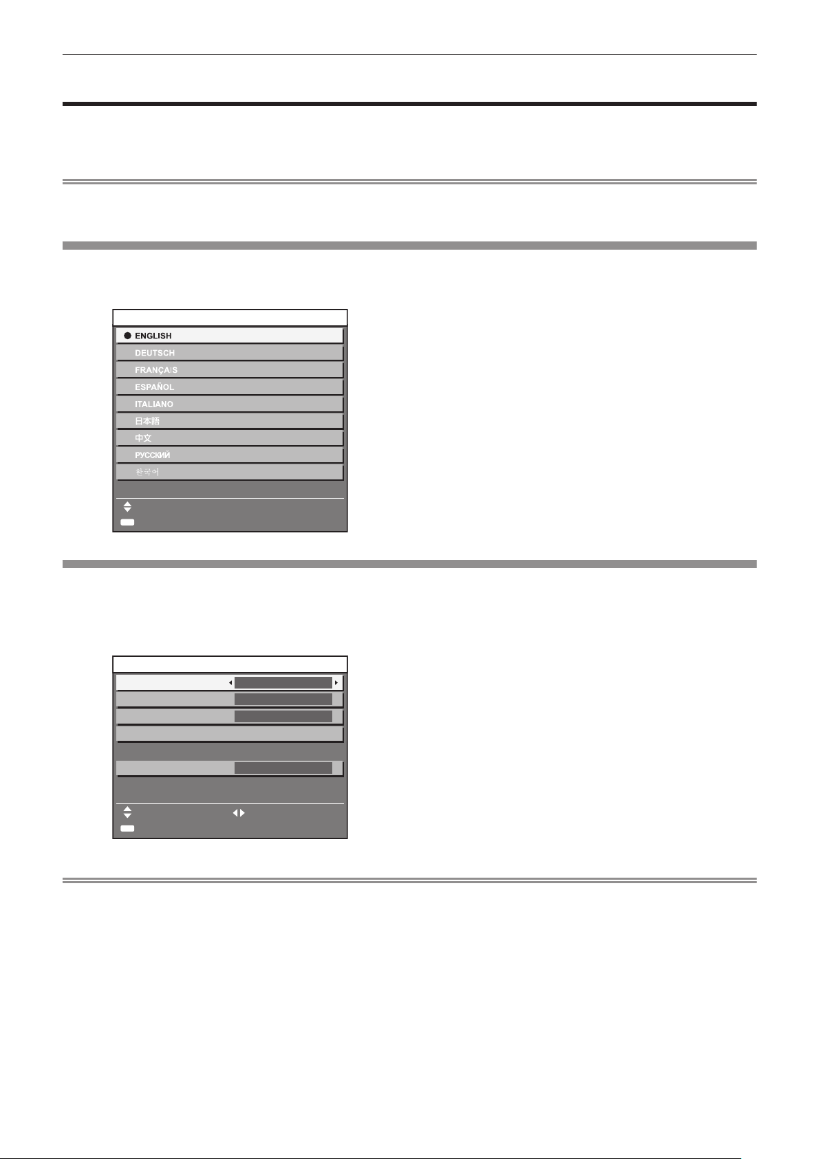
Initial setting (display language)
Select the language to show on the screen. (x page 67)
Press as to select the display language.
1)
,1,7,$/6(77,1*
3/($6(6(/(&7/$1*8$*(
6(/(&7
(17(5
6(7
Initial setting (projector setup)
Set each item.
Press as to select an item.
1)
Press qw to switch the setting.
2)
,1,7,$/6(77,1*
352-(&7,210(7+2'
&22/,1*&21',7,21
6&5((1)250$7
6&5((1326,7,21
)5217)/225
)/2256(77,1*
㧦
Press the <ENTER> button to proceed to the
2)
initial setting.
Refer to the following pages for details.
rf
[PROJECTION METHOD] (x page 75)
[COOLING CONDITION] (x page 76)
[SCREEN FORMAT] (x page 69)
[SCREEN POSITION] (x page 69)
[HIGH ALTITUDE MODE] (x page 76)
Press the <ENTER> button.
3)
Conrm the setting value to complete the initial setting.
rf
+,*+$/7,78'(02'(
6:,7&+72+,*+$/7,78'(02'(21
,)29(5P)W
0(186(/(&7 &+$1*(
(17(5
6(7
2))
Note
If you press the <MENU> button in the initial setting (projector setup) screen, you can go back to the initial setting (display language)
rf
screen.
ENGLISH - 19
Page 20
Chapter 1 Preparation — About your projector
)URQW 7RS
About your projector
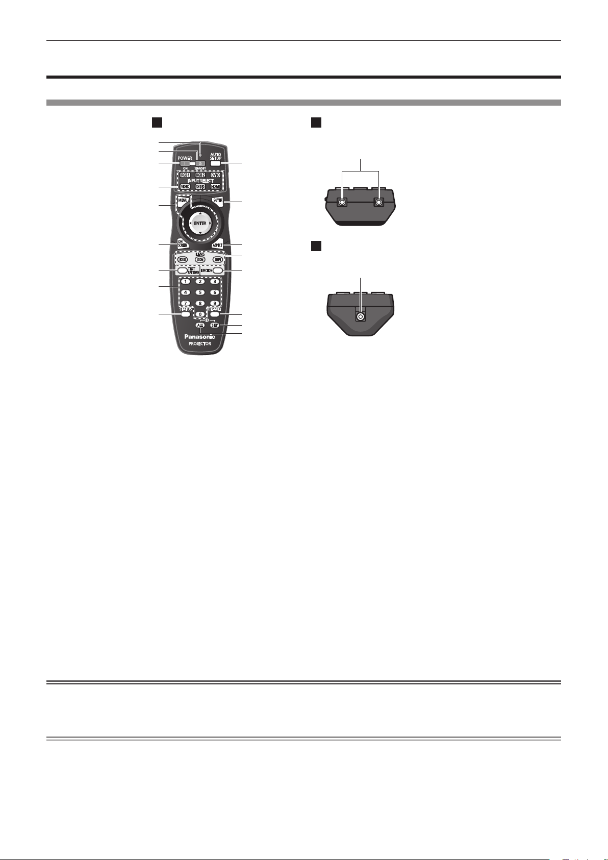
Remote control
1 Remote control indicator
Flashes if any button in the remote control is pressed.
2 Power standby <v> button
Sets the projector to the standby mode when the <MAIN
POWER> switch on the projector is set to <ON>.
3 Power on <b> button
Starts projection when the <MAIN POWER> switch on the
projector is set to <ON> and the power is switched off (standby
mode).
4 Input selection (<RGB1>, <RGB2>, <DVI-D>, <VIDEO>,
<S-VIDEO>, <HDMI>) buttons
Switches the input signal to project. (x page 48)
5 <MENU> button/<ENTER> button/
Used to operate the menu screen. (x page 51)
6 <ON SCREEN> button
Switches the on-screen display function on (displayed)/off
(hidden). (x page 47)
7 <TEST PATTERN> button
Displays the test pattern. (x page 49)
8 Number (<0> - <9>) buttons
Used when the system uses multiple projectors.
Used to input ID numbers or passwords.
9 <STATUS> button
Displays the projector information.
Attention
asqw
buttons
%RWWRP
10 <AUTO SETUP> button
Automatically adjusts the image display position while projecting
the image.
[PROGRESS] is displayed on the screen while the image is
adjusted automatically. (x page 48)
11 <SHUTTER> button
Use to temporarily turn off the image. (x page 47)
12 <ASPECT> button
Switches the aspect ratio of the image. (x page 49)
13 Lens (<FOCUS>, <ZOOM>, <SHIFT>) buttons
Adjusts the projection lens. (x pages 43, 45)
14 <FUNCTION> button
You can assign a frequently used operation as a shortcut button.
(x page 49)
15 <DEFAULT> button
Resets the content of the sub-menu to the factory default.
(x page 51)
16 <ID SET> button
Sets the ID number of the remote control when a system uses
multiple projectors. (x page 23)
17 <ID ALL> button
Use to simultaneously control all the projectors with one remote
control when a system uses multiple projectors. (x page 23)
18 Remote control signal transmitter
19 Remote control wired terminal
Connecting to the projector with a cable
(x page 24)
Do not drop the remote control.
rf
Avoid contact with liquids or moisture.
rf
Do not attempt to modify or disassemble the remote control.
rf
Note
The remote control can be used within a distance of about 30 m (98'5") if pointed directly at the remote control receiver. The remote control
rf
can control at angles of up to ±15° vertically and ±30° horizontally, but the effective control range may be reduced.
If there are any obstacles between the remote control and the remote control signal receiver, the remote control may not operate properly.
rf
The signal will be reected off the screen. However, the operating range may be limited from light reection loss due to the screen material.
rf
If the remote control signal receiver directly receives strong light, such as uorescent light, the remote control may not operate properly.
rf
Use it in a place distant from the light source.
The power indicator <ON (G)/STANDBY (R)> will ash if the projector receives a remote control signal.
rf
20 - ENGLISH
Page 21

Projector body
)URQW 6LGH
%RWWRP
Chapter 1 Preparation — About your projector
5HDU
)URQW
Warning
)URQW
)URQW
8 Projection lens
(for models with attached lenses only)
9 Air exhaust port
10 Lamp unit cover (x page 114)
11 Control panel (x page 22)
12 Remote control signal receiver (rear)
13 Air intake port
14 Connecting terminals (x page 22)
15 <MAIN POWER> switch
Turns on/off the main power.
16 Security slot
This security slot is compatible with the Kensington security
cables.
17 <AC IN> terminal
Connect the supplied power cord.
18 Air lter cover
The air lter unit is inside. (x page 112)
19 Burglar hook port
You can attach a commercial burglar prevention cable.
Keep your hands and other objects away from the air exhaust
port.
Keep your hands and face away.
rf
Do not insert your ngers.
rf
Keep heat-sensitive objects away.
rf
Heated air from the air outlet port can cause bums, injury, or
deformations.
1 Power indicator <ON (G)/STANDBY (R)>
Displays the status of the power.
2 Lamp indicator <LAMP1>
Displays the status of lamp 1.
3 Lamp indicator <LAMP2>
Displays the status of lamp 2.
4 Temperature indicator <TEMP>
Displays the internal temperature status.
5 Filter indicator <FILTER>
Displays the status of the air lter unit.
6 Adjustable feet
Adjusts the projection angle.
7 Remote control signal receiver (front)
ENGLISH - 21
Page 22
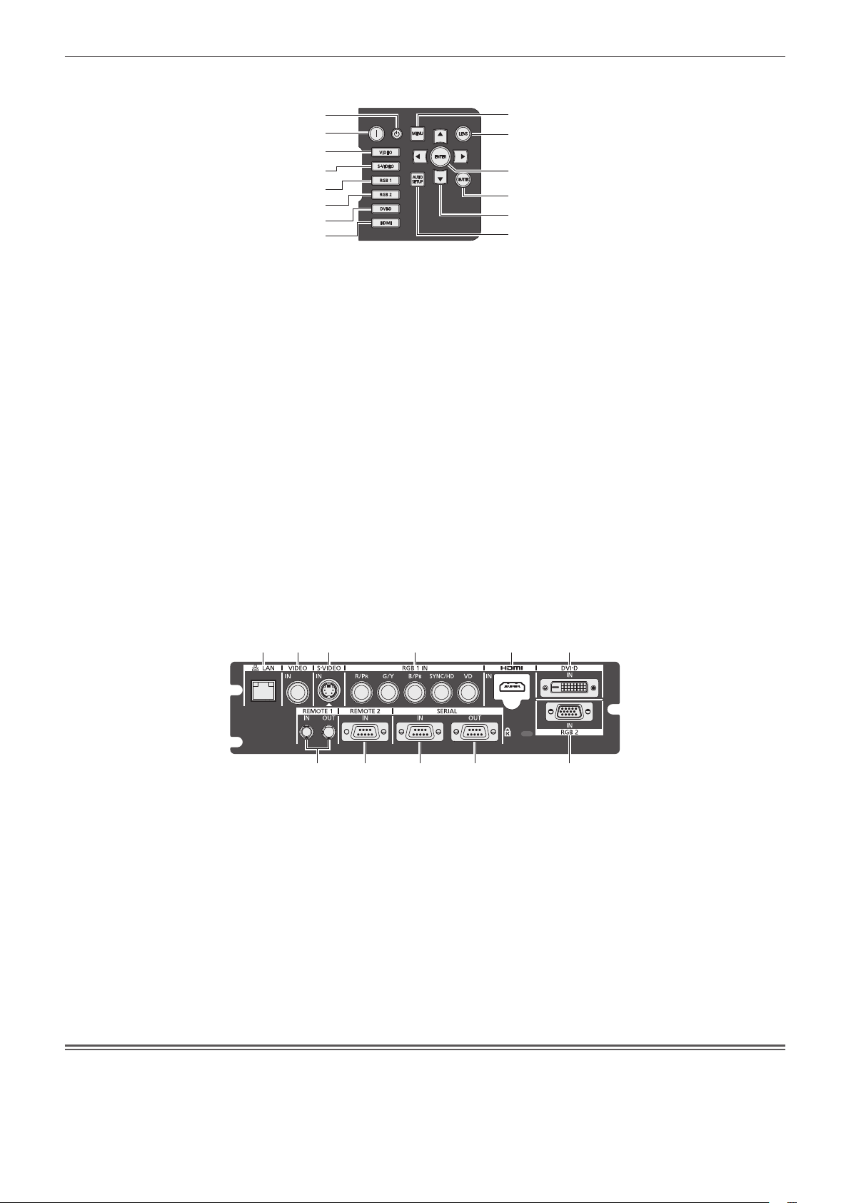
Control panel
rr
Chapter 1 Preparation — About your projector
1
2
3
4
5
6
7
8
1 Power standby <v> button
Sets the projector to the standby mode when the <MAIN
POWER> switch on the projector is set to <ON>.
2 Power on <b> button
Starts projection when the <MAIN POWER> switch on the
projector is set to <ON> when the power is switched off (standby
mode).
3 <VIDEO> button
Switches to VIDEO input.
4 <S-VIDEO> button
Switches to S-VIDEO input.
5 <RGB1> button
Switches to RGB1 input.
6 <RGB2> button
Switches to RGB2 input.
7 <DVI-D> button
Switches to DVI-D input.
8 <HDMI> button
Switches to HDMI input.
9
10
11
12
13
14
9 <MENU> button
Displays and erases the main menu.
Returns to the previous screen when a sub-menu is displayed.
(x page 51)
If you press the <MENU> button on the control panel for at
least three seconds while the on-screen indication is off, the onscreen display is turned on.
10 <LENS> button
Adjusts the focus, zoom, and shift (position) of the lens.
11 <ENTER> button
Determines and executes an item in the menu screen.
12 <SHUTTER> button
Use to temporarily turn off the image. (x page 47)
13
asqw
Use to select items in the menu screen, change settings, and
adjust levels.
It is also used to enter [SECURITY] passwords.
14 <AUTO SETUP> button
Automatically adjusts the image display position while projecting
the image.
[PROGRESS] is displayed on the screen while the image is
adjusted automatically. (x page 48)
selection buttons
Connecting terminals
rr
1 2 3 4 5 6
7 8 9 10 11
1 <LAN> terminal
This is a terminal to connect to the network.
Used for control and monitoring. Image input through network
connections is not possible.
2 <VIDEO IN> terminal
This is a terminal to input video signals.
3 <S-VIDEO IN> terminal
This is a terminal to input S video signals.
4 <RGB 1 IN> (<R/P
terminal
This is a terminal to input RGB signals or YCBCR/YPBPR signals.
5 <HDMI IN> terminal
This is a terminal to input HDMI signals.
6 <DVI-D IN> terminal
This is a terminal to input DVI-D signals.
>, <G/Y>, <B/PB>, <SYNC/HD>, <VD>)
R
Attention
7 <REMOTE 1 IN> terminal / <REMOTE 1 OUT> terminal
These are the terminals to connect the remote control for serial
control when the system uses multiple projectors.
8 <REMOTE 2 IN> terminal
This is a terminal to remotely control the projector using the
external control circuit.
9 <SERIAL IN> terminal
This is a RS-232C compatible terminal to externally control the
projector by connecting a computer.
10 <SERIAL OUT> terminal
This is a terminal to output the signal connected to the <SERIAL
IN> terminal.
11 <RGB 2 IN> terminal
This is a terminal to input RGB signals or YC
/YPBPR signals.
BCR
When a LAN cable is directly connected to the projector, the network connection must be made indoors.
rf
22 - ENGLISH
Page 23

Chapter 1 Preparation — Using the remote control
Using the remote control
Inserting and removing the batteries
Open the cover.
1)
Insert the batteries and close the cover (insert
2)
the m side first).
(ii)
(i)
When removing the batteries, perform the steps in reverse
rf
order.
Setting Remote control ID numbers
When you use the system with multiple projectors, you can operate all the projectors simultaneously or each projector individually using single
remote control, if a unique ID number is assigned to each projector.
After setting the ID number of the projector, set the same ID number on the remote control.
The factory default ID number of the projector is set to [ALL]. When using a single projector, press the <ID ALL> button on the
remote control. Also, you can control a projector if you press the <ID ALL> button on the remote control even if you do not know the
projector ID.
How to set
Press the <ID SET> button on the remote
1)
control.
Within five seconds, press the two-digit ID
2)
number set on the projector using the number
(<0> - <9>) buttons.
If you press the <ID ALL> button, you can operate the projectors
rf
regardless of the setting of the projector’s ID number.
Attention
Since the ID number of the remote control can be set without the projector, do not press the <ID SET> button carelessly. If the <ID SET>
rf
button is pressed and no number (<0> - <9>) buttons are pressed within the next ve seconds, the ID number returns to its original value
before the <ID SET> button was pressed.
The ID number set on the remote control will be stored unless it is set again. However, it will be erased if the remote control is left with dead
rf
batteries. Set the same ID number again when the batteries are replaced.
Note
Set the ID number of the projector from the [PROJECTOR SETUP] menu → [PROJECTOR ID] (x page 75).
rf
ENGLISH - 23
Page 24
Chapter 1 Preparation — Using the remote control
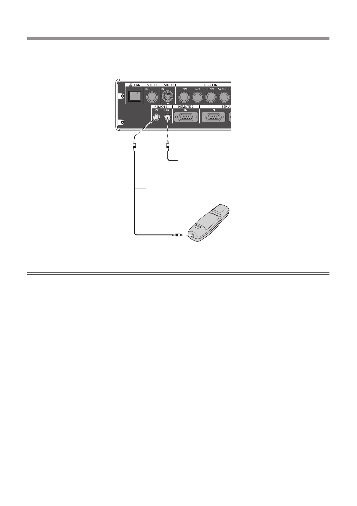
Connecting to the projector with a cable
When you use the system with multiple projectors, congure the units as in the following gure. Use a commercial M3 stereo mini jack cable
and connect the other devices to the <REMOTE 1 IN>/<REMOTE 1 OUT> terminals of the projector.
The remote control is effective even in places where an obstacle stands in the light path or where devices are susceptible to outside light.
&RQQHFWLQJWHUPLQDOV
&RQQHFWLRQWRWKH
VHFRQGSURMHFWRU
0VWHUHRPLQLMDFNFDEOH
FRPPHUFLDOO\DYDLODEOH
5HPRWHFRQWURO
&RQQHFWWRUHPRWHFRQWURO
ZLUHGWHUPLQDO
Attention
Use a cable that is 15 m (49'2") or shorter, with 2 core shield. The remote control may not operate when the length of the cable exceeds 15
rf
m (49'2") or when the shielding of the cable is inadequate.
24 - ENGLISH
Page 25

Chapter 2
This chapter describes about things you need to do before using the projector such as the setup and connections.
Getting Started
ENGLISH - 25
Page 26

Chapter 2 Getting Started — Setting up
Setting up
Projection method
You can use the projector with any of the following four projection methods. Select the appropriate method depending on the environment.
Mounting on the ceiling and projecting forward Setting on a desk/oor and projecting from rear
(Using the translucent screen)
Menu item
[PROJECTION METHOD] [FRONT/CEILING] [PROJECTION METHOD] [REAR/FLOOR]
[COOLING CONDITION] [CEILING SETTING] [COOLING CONDITION] [FLOOR SETTING]
Mounting on the ceiling and projecting from rear
(Using the translucent screen)
Menu item
[PROJECTION METHOD] [REAR/CEILING] [PROJECTION METHOD] [FRONT/FLOOR]
[COOLING CONDITION] [CEILING SETTING] [COOLING CONDITION] [FLOOR SETTING]
* For menu item details, refer to the [PROJECTOR SETUP] menu → [PROJECTION METHOD] (x page 75) and [COOLING CONDITION]
(x page 76).
*
*
Method Menu item
Setting on a desk/oor and projecting forward
Method Menu item
*
*
Method
Method
Parts for ceiling mount (optional)
You can install the projector on the ceiling using the optional ceiling mount bracket (ET-PKD56H: for high ceilings, or ET-PKD55S: for low
ceilings).
Use only the ceiling mount brackets specied for this projector.
rf
Refer to the installation manual for the ceiling mount bracket when installing the bracket and the projector.
rf
Attention
To ensure projector performance and security, installation of the ceiling mount bracket must be carried out by your dealer or a qualied
rf
technician.
26 - ENGLISH
Page 27
Chapter 2 Getting Started — Setting up
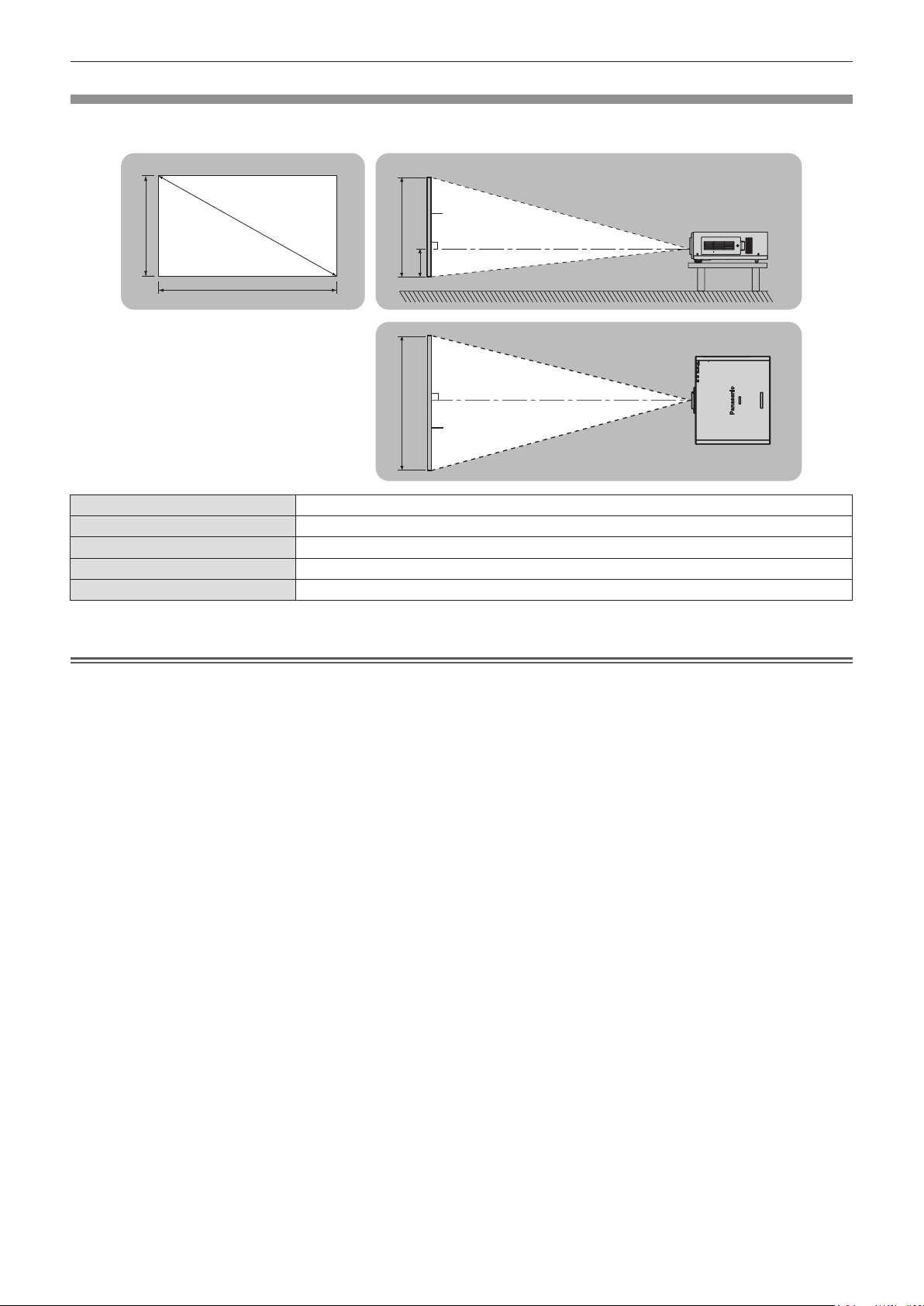
Screen size and throw distance
Refer to the following gures and table describing projection distances to install the projector. Image size and image position can be adjusted
in accordance with the screen size and screen position.
3URMHFWLRQVFUHHQ
6'
6+
6:
L (LW/LT)
* LW: Minimum projection distance when the zoom lens is used
LT: Maximum projection distance when the zoom lens is used
*
SH Image height (m)
SW Image width (m)
H Distance (m) from the lens center to the bottom edge of the image
SD Image diagonal size (m)
Projection distance (m)
Attention
6FUHHQ
//:/7
+
//:/7
6: 6+
6FUHHQ
Before setting up, read “Precautions for use” (x pages 14 to 18).
rf
Do not use the projector and the high-powered laser equipment in the same room.
rf
Hitting of a laser beam on to the lens can damage the DLP chips.
ENGLISH - 27
Page 28

Chapter 2 Getting Started — Setting up
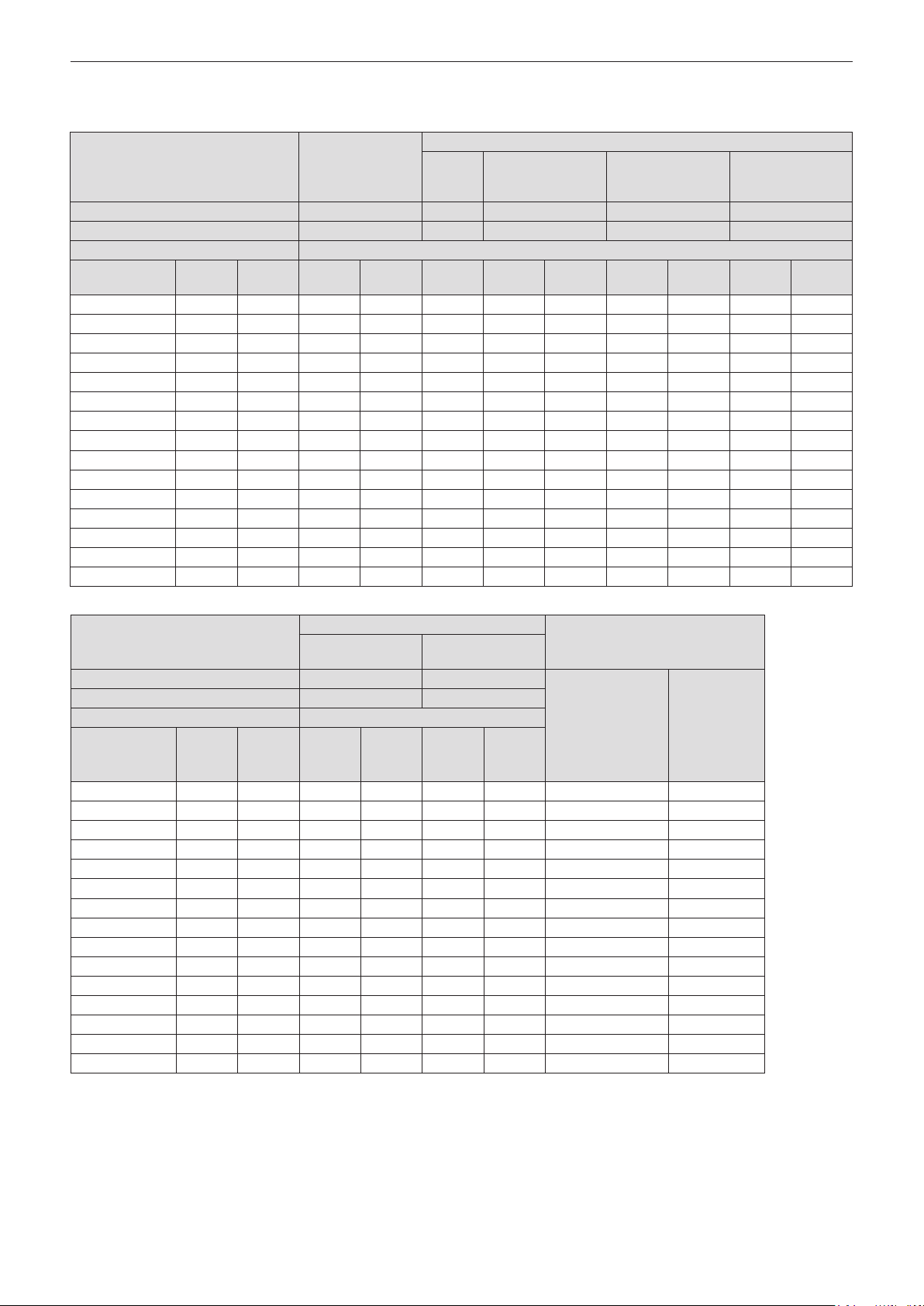
Projection distance per projection lens
For PT-DW640E
When the screen aspect is 16:10 (unit: m)
rr
(The dimensions of the following table contain slight error.)
Optional lens
Lens type Standard zoom lens
Projection lens Model No. ― ET-DLE055 ET-DLE080 ET-DLE150 ET-DLE250
Throw ratio
Projection screen size Projection distance (L)
Screen diagonal
(SD)
1.27 (50") 0.673 1.077 1.92 2.56 0.87 0.87 1.09 1.45 2.12 2.54 4.06
1.52 (60") 0.808 1.292 2.32 3.08 1.06 1.05 1.32 1.75 2.55 3.07 4.89
1.78 (70") 0.942 1.508 2.72 3.61 1.24 1.23 1.54 2.05 2.98 3.59 5.72
2.03 (80") 1.077 1.723 3.11 4.13 1.42 1.42 1.77 2.35 3.42 4.12 6.55
2.29 (90") 1.212 1.939 3.51 4.65 1.61 1.60 2.00 2.65 3.85 4.64 7.38
2.54 (100") 1.346 2.154 3.91 5.18 1.79 1.78 2.22 2.95 4.28 5.16 8.20
3.05 (120") 1.615 2.585 4.70 6.23 2.16 2.15 2.68 3.55 5.15 6.21 9.86
3.81 (150") 2.019 3.231 5.90 7.80 2.71 2.70 3.36 4.45 6.45 7.79 12.35
5.08 (200") 2.692 4.308 7.88 10.42 3.63 3.61 4.49 5.95 8.61 10.41 16.49
6.35 (250") 3.365 5.385 9.87 13.04 ― 4.53 5.62 7.45 10.78 13.03 20.63
7.62 (300") 4.039 6.462 11.86 15.66 ― 5.45 6.76 8.95 12.95 15.65 24.77
8.89 (350") 4.712 7.539 13.85 18.28 ― 6.36 7.89 10.46 15.11 18.28 28.91
10.16 (400") 5.385 8.616 15.83 20.90 ― 7.28 9.02 11.96 17.28 20.90 33.05
12.7 (500") 6.731 10.770 19.81 26.15 ― 9.11 11.29 14.96 21.61 26.14 41.34
15.24 (600") 8.077 12.923 23.78 31.39 ― 10.94 13.55 17.96 25.94 31.39 49.62
*1
1.8 – 2.4:1 0.8:1 0.8 – 1.0:1 1.4 – 2.0:1 2.4 – 3.8:1
Height
(SH)
Width
(SW)
Min. Max. Fixed Min. Max. Min. Max. Min. Max.
Fixed-
focus
lens
Ultra-short focus
zoom lens
Short focus zoom
lens
Medium focus zoom
lens
Optional lens
Lens type
Projection lens Model No. ET-DLE350 ET-DLE450 Standard zoom
Throw ratio
Projection screen size Projection distance (L)
Screen diagonal
(SD)
1.27 (50") 0.673 1.077 4.00 6.11 5.96 9.59
1.52 (60") 0.808 1.292 4.83 7.36 7.21 11.57
1.78 (70") 0.942 1.508 5.65 8.61 8.46 13.55
2.03 (80") 1.077 1.723 6.48 9.86 9.71 15.53
2.29 (90") 1.212 1.939 7.31 11 .11 10.96 17.51
2.54 (100") 1.346 2.154 8.13 12.36 12.21 19.49
3.05 (120") 1.615 2.585 9.79 14.86 14.72 23.45
3.81 (150") 2.019 3.231 12.27 18.61 18.47 29.38
5.08 (200") 2.692 4.308 16.40 24.85 24.73 39.28
6.35 (250") 3.365 5.385 20.53 31.10 30.99 49.17
7.62 (300") 4.039 6.462 24.67 37.34 37.25 59.06
8.89 (350") 4.712 7.539 28.80 43.59 43.51 68.96
10.16 (400") 5.385 8.616 32.94 49.84 49.76 78.85
12.7 (500") 6.731 10.770 41.20 62.33 62.28 98.64
15.24 (600") 8.077 12.923 49.47 74.82 74.80 118.42
*1 The throw ratio is based on the value during projection onto a 2.03-m (80") screen size.
*2 The height position (H) is SH/2 because lens shift cannot be used when a xed-focus lens (Model No.:ET-DLE055) is attached.
*1
3.8 – 5.7:1 5.6 – 9.0:1
Height
(SH)
Width
(SW)
Long focus zoom
lens
Min. Max. Min. Max.
Ultra-long focus
zoom lens
Height position
lens/
ET-DLE080/
ET-DLE150/
ET-DLE250/
ET-DLE350/
ET-DLE450
-
0.07 - 0.34 0.34
-
0.08 - 0.40 0.40
-
0.09 - 0.47 0.47
-
0.11 - 0.54 0.54
-
0.12 - 0.61 0.61
-
0.13 - 0.67 0.67
-
0.16 - 0.81 0.81
-
0.20 - 1.01 1.01
-
0.27 - 1.35 1.35
-
0.34 - 1.68 ―
-
0.40 - 2.02 ―
-
0.47 - 2.36 ―
-
0.54 - 2.69 ―
-
0.67 - 3.37 ―
-
0.81 - 4.04 ―
(H)
*2
ET-DLE055
(Fixed)
28 - ENGLISH
Page 29
Chapter 2 Getting Started — Setting up
When the screen aspect is 16:9 (unit: m)
rr
(The dimensions of the following table contain slight error.)
Optional lens
Lens type Standard zoom lens
Projection lens Model No. ― ET-DLE055 ET-DLE080 ET-DLE150 ET-DLE250
Throw ratio
Projection screen size Projection distance (L)
Screen diagonal
(SD)
1.27 (50") 0.623 1.107 1.98 2.63 0.90 0.89 1.12 1.49 2.18 2.62 4.18
1.52 (60") 0.747 1.328 2.39 3.17 1.09 1.08 1.35 1.80 2.62 3.15 5.03
1.78 (70") 0.872 1.550 2.79 3.71 1.27 1.27 1.59 2.11 3.07 3.69 5.88
2.03 (80") 0.996 1.771 3.20 4.25 1.46 1.46 1.82 2.42 3.51 4.23 6.73
2.29 (90") 1.121 1.992 3.61 4.78 1.65 1.65 2.05 2.72 3.96 4.77 7.58
2.54 (100") 1.245 2.214 4.02 5.32 1.84 1.83 2.29 3.03 4.40 5.31 8.43
3.05 (120") 1.494 2.657 4.84 6.40 2.22 2.21 2.75 3.65 5.29 6.39 10.14
3.81 (150") 1.868 3.321 6.06 8.02 2.79 2.78 3.45 4.58 6.63 8.01 12.69
5.08 (200") 2.491 4.428 8.10 10.71 3.73 3.72 4.61 6.12 8.86 10.70 16.95
6.35 (250") 3.113 5.535 10.15 13.40 ― 4.66 5.78 7.66 11.08 13.40 21.21
7.62 (300") 3.736 6.641 12.19 16.10 ― 5.60 6.94 9.21 13.31 16.09 25.46
8.89 (350") 4.358 7.748 14.23 18.79 ― 6.54 8.11 10.75 15.53 18.79 29.72
10.16 (400") 4.981 8.855 16.27 21.49 ― 7.48 9.27 12.29 17.76 21.48 33.98
12.7 (500") 6.226 11.069 20.36 26.87 ― 9.36 11.60 15.38 22.21 26.87 42.49
15.24 (600") 7.472 13.283 24.44 32.26 ― 11.24 13.93 18.46 26.66 32.26 51.00
*1
1.8 – 2.4:1 0.8:1 0.8 – 1.0:1 1.4 – 2.0:1 2.4 – 3.8:1
Height
(SH)
Width
(SW)
Min. Max. Fixed Min. Max. Min. Max. Min. Max.
Fixed-
focus
lens
Ultra-short focus
zoom lens
Short focus zoom
lens
Medium focus zoom
lens
Optional lens
Lens type
Projection lens Model No. ET-DLE350 ET-DLE450 Standard zoom
Throw ratio
Projection screen size Projection distance (L)
Screen diagonal
(SD)
1.27 (50") 0.623 1.107 4.11 6.29 6.13 9.87
1.52 (60") 0.747 1.328 4.96 7.57 7.42 11.90
1.78 (70") 0.872 1.550 5.81 8.85 8.70 13.94
2.03 (80") 0.996 1.771 6.66 10.14 9.99 15.97
2.29 (90") 1.121 1.992 7.51 11.42 11.28 18.00
2.54 (100") 1.245 2.214 8.36 12.71 12.56 20.04
3.05 (120") 1.494 2.657 10.06 15.27 15.14 24.11
3.81 (150") 1.868 3.321 12.61 19.13 18.99 30.21
5.08 (200") 2.491 4.428 16.86 25.55 25.43 40.38
6.35 (250") 3.113 5.535 21.11 31.97 31.86 50.54
7.62 (300") 3.736 6.641 25.36 38.39 38.29 60.71
8.89 (350") 4.358 7.748 29.61 44.81 44.72 70.88
10.16 (400") 4.981 8.855 33.86 51.23 51.16 81.05
12.7 (500") 6.226 11.069 42.35 64.07 64.02 101.39
15.24 (600") 7.472 13.283 50.85 76.91 76.88 121.73
*1 The throw ratio is based on the value during projection onto a 2.03-m (80") screen size.
*2 The height position (H) is SH/2 because lens shift cannot be used when a xed-focus lens (Model No.:ET-DLE055) is attached.
*1
3.8 – 5.7:1 5.6 – 9.0:1
Height
(SH)
Width
(SW)
Long focus zoom
lens
Min. Max. Min. Max.
Ultra-long focus
zoom lens
Height position
lens/
ET-DLE080/
ET-DLE150/
ET-DLE250/
ET-DLE350/
ET-DLE450
-
0.14 - 0.31 0.31
-
0.16 - 0.37 0.37
-
0.19 - 0.44 0.44
-
0.22 - 0.50 0.50
-
0.25 - 0.56 0.56
-
0.27 - 0.62 0.62
-
0.33 - 0.75 0.75
-
0.41 - 0.93 0.93
-
0.55 - 1.25 1.25
-
0.68 - 1.56 ―
-
0.82 - 1.87 ―
-
0.96 - 2.18 ―
-
1.10 - 2.49 ―
-
1.37 - 3.11 ―
-
1.64 - 3.74 ―
(H)
*2
ET-DLE055
(Fixed)
ENGLISH - 29
Page 30

Chapter 2 Getting Started — Setting up
When the screen aspect is 4:3 (unit: m)
rr
(The dimensions of the following table contain slight error.)
Optional lens
Lens type Standard zoom lens
Projection lens Model No. ― ET-DLE055 ET-DLE080 ET-DLE150 ET-DLE250
Throw ratio
Projection screen size Projection distance (L)
Screen diagonal
(SD)
1.27 (50") 0.762 1.016 2.18 2.90 0.99 0.99 1.24 1.65 2.40 2.89 4.61
1.52 (60") 0.914 1.219 2.63 3.50 1.20 1.20 1.50 1.99 2.89 3.48 5.55
1.78 (70") 1.067 1.422 3.08 4.09 1.41 1.40 1.75 2.33 3.38 4.08 6.48
2.03 (80") 1.219 1.626 3.53 4.68 1.62 1.61 2.01 2.67 3.87 4.67 7.42
2.29 (90") 1.372 1.829 3.98 5.28 1.82 1.82 2.26 3.00 4.36 5.26 8.36
2.54 (100") 1.524 2.032 4.43 5.87 2.03 2.03 2.52 3.34 4.85 5.86 9.30
3.05 (120") 1.829 2.438 5.33 7.06 2.45 2.44 3.03 4.02 5.83 7.04 11.17
3.81 (150") 2.286 3.048 6.68 8.84 3.07 3.06 3.80 5.04 7.31 8.82 13.98
5.08 (200") 3.048 4.064 8.93 11.80 4.11 4.10 5.09 6.74 9.76 11.79 18.67
6.35 (250") 3.810 5.080 11.18 14.77 ― 5.13 6.37 8.44 12.21 14.76 23.36
7.62 (300") 4.572 6.096 13.43 17.73 ― 6.17 7.65 10.14 14.66 17.73 28.05
8.89 (350") 5.334 7.112 15.68 20.70 ― 7.21 8.93 11.84 17.11 20.70 32.74
10.16 (400") 6.096 8.128 17.93 23.67 ― 8.24 10.22 13.54 19.56 23.67 37.42
12.7 (500") 7.620 10.160 22.43 29.60 ― 10.31 12.78 16.94 24.47 29.60 46.80
15.24 (600") 9.144 12.192 26.92 35.53 ― 12.39 15.35 20.34 29.37 35.54 56.17
*1
2.2 – 2.9:1 1.0:1 1.0 – 1.2:1 1.6 – 2.4:1 2.9 – 4.6:1
Height
(SH)
Width
(SW)
Min. Max. Fixed Min. Max. Min. Max. Min. Max.
Fixed-
focus
lens
Ultra-short focus
zoom lens
Short focus zoom
lens
Medium focus zoom
lens
Optional lens
Lens type
Projection lens Model No. ET-DLE350 ET-DLE450 Standard zoom
Throw ratio
Projection screen size Projection distance (L)
Screen diagonal
(SD)
1.27 (50") 0.762 1.016 4.54 6.94 6.78 10.90
1.52 (60") 0.914 1.219 5.48 8.35 8.20 13.14
1.78 (70") 1.067 1.422 6.42 9.76 9.61 15.38
2.03 (80") 1.219 1.626 7.35 11.18 11.03 17.62
2.29 (90") 1.372 1.829 8.29 12.59 12.45 19.86
2.54 (100") 1.524 2.032 9.22 14.01 13.87 22.10
3.05 (120") 1.829 2.438 11.09 16.83 16.70 26.58
3.81 (150") 2.286 3.048 13.90 21.08 20.95 33.30
5.08 (200") 3.048 4.064 18.58 28.15 28.03 44.49
6.35 (250") 3.810 5.080 23.26 35.22 35.12 55.69
7.62 (300") 4.572 6.096 27.94 42.29 42.20 66.89
8.89 (350") 5.334 7.112 32.62 49.36 49.28 78.09
10.16 (400") 6.096 8.128 37.30 56.43 56.37 89.29
12.7 (500") 7.620 10.160 46.65 70.57 70.53 111.68
15.24 (600") 9.144 12.192 56.01 84.71 84.70 134.08
*1 The throw ratio is based on the value during projection onto a 2.03-m (80") screen size.
*2 The height position (H) is SH/2 because lens shift cannot be used when a xed-focus lens (Model No.:ET-DLE055) is attached.
*1
4.5 – 6.9:1 6.8 – 10.8:1
Height
(SH)
Width
(SW)
Long focus zoom
lens
Min. Max. Min. Max.
Ultra-long focus
zoom lens
Height position
lens/
ET-DLE080/
ET-DLE150/
ET-DLE250/
ET-DLE350/
ET-DLE450
-
0.08 - 0.38 0.38
-
0.09 - 0.46 0.46
-
0.11 - 0.53 0.53
-
0.12 - 0.61 0.61
-
0.14 - 0.69 0.69
-
0.15 - 0.76 0.76
-
0.18 - 0.91 0.91
-
0.23 - 1.14 1.14
-
0.30 - 1.52 1.52
-
0.38 - 1.91 ―
-
0.46 - 2.29 ―
-
0.53 - 2.67 ―
-
0.61 - 3.05 ―
-
0.76 - 3.81 ―
-
0.91 - 4.57 ―
(H)
*2
ET-DLE055
(Fixed)
30 - ENGLISH
Page 31

Chapter 2 Getting Started — Setting up
For PT-DX610E
When the screen aspect is 4:3 (unit: m)
rr
(The dimensions of the following table contain slight error.)
Optional lens
Lens type Standard zoom lens
Projection lens Model No. ― ET-DLE055 ET-DLE080 ET-DLE150 ET-DLE250
Throw ratio
Projection screen size Projection distance (L)
Screen diagonal
(SD)
1.27 (50") 0.762 1.016 1.79 2.38 0.81 0.81 1.01 1.34 1.97 2.36 3.78
1.52 (60") 0.914 1.219 2.16 2.86 0.98 0.98 1.22 1.62 2.37 2.85 4.55
1.78 (70") 1.067 1.422 2.53 3.35 1.15 1.15 1.43 1.90 2.77 3.34 5.32
2.03 (80") 1.219 1.626 2.90 3.84 1.32 1.32 1.64 2.18 3.18 3.83 6.09
2.29 (90") 1.372 1.829 3.27 4.33 1.49 1.49 1.85 2.46 3.58 4.31 6.86
2.54 (100") 1.524 2.032 3.64 4.82 1.66 1.66 2.07 2.74 3.98 4.80 7.63
3.05 (120") 1.829 2.438 4.38 5.79 2.01 2.00 2.49 3.30 4.79 5.78 9.17
3.81 (150") 2.286 3.048 5.49 7.26 2.52 2.51 3.12 4.14 6.00 7.24 11.49
5.08 (200") 3.048 4.064 7.34 9.70 3.38 3.36 4.18 5.54 8.02 9.69 15.34
6.35 (250") 3.810 5.080 9.19 12.14 ― 4.21 5.23 6.94 10.03 12.13 19.20
7.62 (300") 4.572 6.096 11.04 14.58 ― 5.07 6.29 8.33 12.05 14.57 23.06
8.89 (350") 5.334 7.112 12.89 17.02 ― 5.92 7.34 9.73 14.07 17.01 26.91
10.16 (400") 6.096 8.128 14.74 19.46 ― 6.77 8.40 11.13 16.08 19.45 30.77
12.7 (500") 7.620 10.160 18.44 24.34 ― 8.48 10.51 13.92 20.12 24.33 38.48
15.24 (600") 9.144 12.192 22.14 29.22 ― 10.18 12.62 16.72 24.15 29.22 46.19
*1
1.8 – 2.4:1 0.8:1 0.8 – 1.0:1 1.3 – 2.0:1 2.4 – 3.7:1
Height
(SH)
Width
(SW)
Min. Max. Fixed Min. Max. Min. Max. Min. Max.
Fixed-
focus
lens
Ultra-short focus
zoom lens
Short focus zoom
lens
Medium focus zoom
lens
Optional lens
Lens type
Projection lens Model No. ET-DLE350 ET-DLE450 Standard zoom
Throw ratio
Projection screen size Projection distance (L)
Screen diagonal
(SD)
1.27 (50") 0.762 1.016 3.71 5.68 5.52 8.91 0 - 0.38 0.04 - 0.38 0.38
1.52 (60") 0.914 1.219 4.48 6.84 6.69 10.75 0 - 0.46 0.05 - 0.46 0.46
1.78 (70") 1.067 1.422 5.25 8.01 7.86 12.60 0 - 0.53 0.05 - 0.53 0.53
2.03 (80") 1.219 1.626 6.02 9.17 9.02 14.44 0 - 0.61 0.06 - 0.61 0.61
2.29 (90") 1.372 1.829 6.79 10.33 10.19 16.28 0 - 0.69 0.07 - 0.69 0.69
2.54 (100") 1.524 2.032 7.56 11.50 11.35 18.12 0 - 0.76 0.08 - 0.76 0.76
3.05 (120") 1.829 2.438 9.10 13.82 13.68 21.81 0 - 0.91 0.09 - 0.91 0.91
3.81 (150") 2.286 3.048 11.41 17.31 17.18 27.33 0 - 1.14 0.11 - 1.14 1.14
5.08 (200") 3.048 4.064 15.26 23.13 23.00 36.54 0 - 1.52 0.15 - 1.52 1.52
6.35 (250") 3.810 5.080 19.11 28.94 28.83 45.75 0 - 1.91 0.19 - 1.91 ―
7.62 (300") 4.572 6.096 22.96 34.76 34.66 54.97 0 - 2.29 0.23 - 2.29 ―
8.89 (350") 5.334 7.112 26.80 40.57 40.48 64.18 0 - 2.67 0.27 - 2.67 ―
10.16 (400") 6.096 8.128 30.65 46.39 46.31 73.39 0 - 3.05 0.30 - 3.05 ―
12.7 (500") 7.620 10.160 38.35 58.02 57.96 91.81 0 - 3.81 0.38 - 3.81 ―
15.24 (600") 9.144 12.192 46.05 69.65 69.61 110.23 0 - 4.57 0.46 - 4.57 ―
*1 The throw ratio is based on the value during projection onto a 2.03-m (80") screen size.
*2 The height position (H) is SH/2 because lens shift cannot be used when a xed-focus lens (Model No.:ET-DLE055) is attached.
*1
3.7 – 5.6:1 5.5 – 8.9:1
Height
(SH)
Width
(SW)
Long focus zoom
lens
Min. Max. Min. Max.
Ultra-long focus
zoom lens
lens/
ET-DLE150/
ET-DLE250/
ET-DLE350/
ET-DLE450
Height position
*2
(H)
ET-DLE080
ET-DLE055
(Fixed)
ENGLISH - 31
Page 32

Chapter 2 Getting Started — Setting up
When the screen aspect is 16:9 (unit: m)
rr
(The dimensions of the following table contain slight error.)
Optional lens
Lens type Standard zoom lens
Projection lens Model No. ― ET-DLE055 ET-DLE080 ET-DLE150 ET-DLE250
Throw ratio
Projection screen size Projection distance (L)
Screen diagonal
(SD)
1.27 (50") 0.623 1.107 1.95 2.59 0.88 0.88 1.11 1.47 2.15 2.58 4.12
1.52 (60") 0.747 1.328 2.35 3.13 1.07 1.07 1.34 1.77 2.59 3.11 4.96
1.78 (70") 0.872 1.550 2.76 3.66 1.26 1.25 1.57 2.08 3.03 3.64 5.80
2.03 (80") 0.996 1.771 3.16 4.19 1.44 1.44 1.79 2.38 3.47 4.18 6.64
2.29 (90") 1.121 1.992 3.56 4.72 1.63 1.62 2.02 2.69 3.90 4.71 7.48
2.54 (100") 1.245 2.214 3.97 5.25 1.82 1.81 2.25 2.99 4.34 5.24 8.32
3.05 (120") 1.494 2.657 4.77 6.32 2.19 2.18 2.71 3.60 5.22 6.30 10.00
3.81 (150") 1.868 3.321 5.98 7.91 2.75 2.74 3.40 4.51 6.54 7.90 12.52
5.08 (200") 2.491 4.428 8.00 10.57 3.68 3.67 4.55 6.04 8.74 10.56 16.72
6.35 (250") 3.113 5.535 10.01 13.23 ― 4.60 5.70 7.56 10.93 13.22 20.93
7.62 (300") 3.736 6.641 12.03 15.89 ― 5.52 6.85 9.08 13.13 15.88 25.13
8.89 (350") 4.358 7.748 14.04 18.54 ― 6.45 8.00 10.61 15.33 18.54 29.33
10.16 (400") 4.981 8.855 16.06 21.20 ― 7.38 9.15 12.13 17.53 21.20 33.53
12.7 (500") 6.226 11.069 20.09 26.52 ― 9.24 11.45 15.17 21.92 26.52 41.93
15.24 (600") 7.472 13.283 24.12 31.84 ― 11.10 13.75 18.22 26.31 31.84 50.33
*1
1.8 – 2.4:1 0.8:1 0.8 – 1.0:1 1.3 – 2.0:1 2.4 – 3.8:1
Height
(SH)
Width
(SW)
Min. Max. Fixed Min. Max. Min. Max. Min. Max.
Fixed-
focus
lens
Ultra-short focus
zoom lens
Short focus zoom
lens
Medium focus zoom
lens
Optional lens
Lens type
Projection lens Model No. ET-DLE350 ET-DLE450 Standard zoom
Throw ratio
Projection screen size Projection distance (L)
Screen diagonal
(SD)
1.27 (50") 0.623 1.107 4.06 6.20 6.05 9.74
1.52 (60") 0.747 1.328 4.90 7.47 7.32 11.74
1.78 (70") 0.872 1.550 5.73 8.74 8.58 13.75
2.03 (80") 0.996 1.771 6.57 10.00 9.85 15.76
2.29 (90") 1.121 1.992 7.41 11.27 11.12 17.76
2.54 (100") 1.245 2.214 8.25 12.54 12.39 19.77
3.05 (120") 1.494 2.657 9.93 15.07 14.93 23.78
3.81 (150") 1.868 3.321 12.44 18.87 18.74 29.81
5.08 (200") 2.491 4.428 16.64 25.21 25.09 39.84
6.35 (250") 3.113 5.535 20.83 31.54 31.44 49.88
7.62 (300") 3.736 6.641 25.02 37.88 37.78 59.91
8.89 (350") 4.358 7.748 29.22 44.22 44.13 69.95
10.16 (400") 4.981 8.855 33.41 50.55 50.48 79.98
12.7 (500") 6.226 11.069 41.79 63.22 63.17 100.05
15.24 (600") 7.472 13.283 50.18 75.89 75.87 120.12
*1 The throw ratio is based on the value during projection onto a 2.03-m (80") screen size.
*2 The height position (H) is SH/2 because lens shift cannot be used when a xed-focus lens (Model No.:ET-DLE055) is attached.
*1
3.7 – 5.6:1 5.6 – 8.9:1
Height
(SH)
Width
(SW)
Long focus
zoom lens
Min. Max. Min. Max.
Ultra-long focus
zoom lens
lens/
ET-DLE150/
ET-DLE250/
ET-DLE350/
ET-DLE450
-
0.21 - 0.31
-
0.25 - 0.37
-
0.29 - 0.44
-
0.33 - 0.50
-
0.37 - 0.56
-
0.41 - 0.62
-
0.49 - 0.75
-
0.62 - 0.93
-
0.82 - 1.25
-
1.03 - 1.56
-
1.23 - 1.87
-
1.44 - 2.18
-
1.64 - 2.49
-
2.05 - 3.11
-
2.47 - 3.74
Height position
*2
(H)
ET-DLE080
-
0.16 - 0.31 0.31
-
0.19 - 0.37 0.37
-
0.23 - 0.44 0.44
-
0.26 - 0.50 0.50
-
0.29 - 0.56 0.56
-
0.32 - 0.62 0.62
-
0.39 - 0.75 0.75
-
0.49 - 0.93 0.93
-
0.65 - 1.25 1.25
-
0.81 - 1.56 ―
-
0.97 - 1.87 ―
-
1.13 - 2.18 ―
-
1.30 - 2.49 ―
-
1.62 - 3.11 ―
-
1.94 - 3.74 ―
ET-DLE055
(Fixed)
32 - ENGLISH
Page 33

Chapter 2 Getting Started — Setting up
Projection distance formulas by projection lens
To use a screen size not listed in this manual, check the screen size SD and use the following formula to calculate projection distance.
The unit of the calculation result is m.
For PT-DW640E
Lens type
Standard zoom lens ―
Fixed-focus lens ET-DLE055
Ultra-short focus zoom
lens
Short focus zoom lens ET-DLE150
Medium focus zoom lens ET-DLE250
Long focus zoom lens ET-DLE350
Ultra-long focus zoom lens ET-DLE450
Projection lens Model No.
ET-DLE080
Aspect ratio Projection distance (L) formula
16:10
16:9
4:3
16:10 ― L = 0.7244 x SD (m) – 0.0476
16:9 ― L = 0.7441 x SD (m) – 0.0476
4:3 ― L = 0.8189 x SD (m) – 0.0476
16:10
16:9
4:3
16:10
16:9
4:3
16:10
16:9
4:3
16:10
16:9
4:3
16:10
16:9
4:3
Min. (LW) L = 1.5630 x SD (m) – 0.0650
Max. (LT) L = 2.0630 x SD (m) – 0.0638
Min. (LW) L = 1.6063 x SD (m) – 0.0650
Max. (LT) L = 2.1220 x SD (m) – 0.0638
Min. (LW) L = 1.7717 x SD (m) – 0.0650
Max. (LT) L = 2.3346 x SD (m) – 0.0638
Min. (LW) L = 0.7205 x SD (m) – 0.0471
Max. (LT) L = 0.8937 x SD (m) – 0.0442
Min. (LW) L = 0.7402 x SD (m) – 0.0471
Max. (LT) L = 0.9173 x SD (m) – 0.0442
Min. (LW) L = 0.8150 x SD (m) – 0.0471
Max. (LT) L = 1.0118 x SD (m) – 0.0442
Min. (LW) L = 1.1811 x SD (m) – 0.0540
Max. (LT) L = 1.7047 x SD (m) – 0.0498
Min. (LW) L = 1.2165 x SD (m) – 0.0540
Max. (LT) L = 1.7520 x SD (m) – 0.0498
Min. (LW) L = 1.3386 x SD (m) – 0.0540
Max. (LT) L = 1.9291 x SD (m) – 0.0498
Min. (LW) L = 2.0630 x SD (m) – 0.0800
Max. (LT) L = 3.2598 x SD (m) – 0.0792
Min. (LW) L = 2.1220 x SD (m) – 0.0800
Max. (LT) L = 3.3504 x SD (m) – 0.0792
Min. (LW) L = 2.3386 x SD (m) – 0.0800
Max. (LT) L = 3.6929 x SD (m) – 0.0792
Min. (LW) L = 3.2559 x SD (m) – 0.1351
Max. (LT) L = 4.9173 x SD (m) – 0.1346
Min. (LW) L = 3.3465 x SD (m) – 0.1351
Max. (LT) L = 5.0551 x SD (m) – 0.1346
Min. (LW) L = 3.6850 x SD (m) – 0.1351
Max. (LT) L = 5.5669 x SD (m) – 0.1346
Min. (LW) L = 4.9291 x SD (m) – 0.3017
Max. (LT) L = 7.7913 x SD (m) – 0.2991
Min. (LW) L = 5.0630 x SD (m) – 0.3017
Max. (LT) L = 8.0079 x SD (m) – 0.2991
Min. (LW) L = 5.5787 x SD (m) – 0.3017
Max. (LT) L = 8.8189 x SD (m) – 0.2991
For PT-DX610E
Lens type
Standard zoom lens ―
Fixed-focus lens ET-DLE055
Projection lens Model No.
Aspect ratio Projection distance (L) formula
4:3
16:9
4:3 ― L = 0.6732 x SD (m) – 0.0476
16:9 ― L = 0.7323 x SD (m) – 0.0476
Min. (LW) L = 1.4567 x SD (m) – 0.0650
Max. (LT) L = 1.9213 x SD (m) – 0.0638
Min. (LW) L = 1.5866 x SD (m) – 0.0650
Max. (LT) L = 2.0945 x SD (m) – 0.0638
ENGLISH - 33
Page 34

Chapter 2 Getting Started — Setting up
Lens type
Ultra-short focus zoom
lens
Short focus zoom lens ET-DLE150
Medium focus zoom lens ET-DLE250
Long focus zoom lens ET-DLE350
Ultra-long focus zoom lens ET-DLE450
Projection lens Model No.
ET-DLE080
Adjusting adjustable feet
Aspect ratio Projection distance (L) formula
4:3
16:9
4:3
16:9
4:3
16:9
4:3
16:9
4:3
16:9
Min. (LW) L = 0.6693 x SD (m) – 0.0471
Max. (LT) L = 0.8307 x SD (m) – 0.0442
Min. (LW) L = 0.7323 x SD (m) – 0.0471
Max. (LT) L = 0.9055 x SD (m) – 0.0442
Min. (LW) L = 1.1024 x SD (m) – 0.0540
Max. (LT) L = 1.5866 x SD (m) – 0.0498
Min. (LW) L = 1.2008 x SD (m) – 0.0540
Max. (LT) L = 1.7283 x SD (m) – 0.0498
Min. (LW) L = 1.9213 x SD (m) – 0.0800
Max. (LT) L = 3.0354 x SD (m) – 0.0792
Min. (LW) L = 2.0945 x SD (m) – 0.0800
Max. (LT) L = 3.3071 x SD (m) – 0.0792
Min. (LW) L = 3.0315 x SD (m) – 0.1351
Max. (LT) L = 4.5787 x SD (m) – 0.1346
Min. (LW) L = 3.3031 x SD (m) – 0.1351
Max. (LT) L = 4.9882 x SD (m) – 0.1346
Min. (LW) L = 4.5866 x SD (m) – 0.3017
Max. (LT) L = 7.2520 x SD (m) – 0.2991
Min. (LW) L = 5.0000 x SD (m) – 0.3017
Max. (LT) L = 7.9016 x SD (m) – 0.2991
Install the projector on a at surface so that the front of the projector is parallel to the screen surface and the projection screen is rectangular.
If the screen is tilted downward, the projection screen can be adjusted to be rectangular by adjusting the adjustable feet. The adjustable feet
can also be used to adjust the projector to be level when it is tilted in a horizontal direction.
Extend the adjustable feet by rotating in the direction shown in the gure and retract by rotating in the opposite direction.
$GMXVWDEOHDPRXQW
)URQWDGMXVWDEOHIHHWPP
Attention
Hot air is expelled from the air exhaust port when the lamp is on. Do not touch the air exhaust port directly when adjusting the adjustable
rf
feet. (x page 21)
34 - ENGLISH
Page 35

Chapter 2 Getting Started — Removing/attaching the projection lens
*XLGHJURRYH
Removing/attaching the projection lens
Attach and remove the projection lens in the same way as a standard zoom lens and optional accessories.
Move the projection lens to the home position before replacing or removing the lens (x page 46).
Attention
Replace the projection lens after turning off the power of the projector.
rf
Do not touch the lens signal receiver. Dust or dirt may cause defective contact.
rf
Do not touch the lens surface with bare hands.
rf
Before attaching the projection lens, remove the lens cover attached to the projection lens.
rf
The procedure to remove/attach a projection lens cover differs for the ultra-short focus zoom lens (ET-DLE080). Refer to the user manual
rf
provided with ET-DLE080 for details.
Removing the projection lens
Remove the projection lens in the following procedure.
Turn the projection lens cover
1)
counterclockwise to remove.
3URMHFWLRQOHQVFRYHU
L
LL
Attention
Store the removed lens where it will be free from vibration and impact.
rf
Attaching the projection lens
Attach the projection lens in the following procedure.
While pressing the lens release button, turn
2)
the projection lens counterclockwise until it
stops.Remove the projection lens.
LLL
3URMHFWLRQOHQV
LL
L
/HQVUHOHDVHEXWWRQ
Remove the projection lens cover and insert
1)
fully by aligning the projection lens guide with
the projector guide grooves.
*XLGH
3URMHFWLRQOHQV
Turn the projection lens clockwise until it
2)
clicks.
ENGLISH - 35
Page 36

Chapter 2 Getting Started — Removing/attaching the projection lens
Attach the projection lens cover aligning the
3)
marking (groove *1) with the tip of the arrow
on the projector (*2), and secure the projection
lens cover by turning it until groove *1 aligns
with the *3 P marking.
L
3URMHFWLRQOHQVFRYHU
*3
*2
*1
LL
Attention
Turn the projection lens counterclockwise to conrm that it does not come out.
rf
36 - ENGLISH
Page 37

Chapter 2 Getting Started — Connections
(1) (2)
(11) (15)
(17)(24)
Connections
Before connecting to the projector
Before connecting, carefully read the operating instructions for the external device to be connected.
rf
Turn off the power of all devices before connecting cables.
rf
Acquire any connection cable necessary to connect the external device to the system that is either not supplied with the device or not
rf
available as an option.
Video signals containing too much jitter may cause the images on the screen to randomly wobble or wafture. In this case, a time base
rf
corrector (TBC) must be connected.
The projector accepts video signals, S video signals, analog RGB signals (synchronous signals are TTL level), and digital signals.
rf
Some computer models are not compatible with the projector.
rf
Use a cable compensator when you connect devices to the projector using long cables. Otherwise the image may not display properly.
rf
Refer to “List of compatible signals” (x page 125) for the types of video signals that can be used with the projector.
rf
<S-VIDEO IN> terminal pin assignments and signal names
Outside view Pin No. Signal name
(1) Ground (luminance signal)
(2) Ground (color signal)
(3) Luminance signal
(3) (4)
(4)
Color signal
<RGB 2 IN> terminal pin assignments and signal names
Outside view Pin No. Signal name
(6)
(1) (5)
(10)
(1) R/P
(2) G/Y
(3) B/P
(12) DDC data
(13) SYNC/HD
(14) VD
(15) DDC clock
R
B
<DVI-D IN> terminal pin assignments and signal names
Outside view Pin No. Signal name Pin No. Signal name
(1) T.M.D.S data 2
(2) T.M.D.S data 2+ (14) +5 V
(3) T.M.D.S data 2/4 shield (15) GND
(4) ― (16) Hot plug detection
(5) ― (17) T.M.D.S data 0
(16) (9)
(1)(8)
(6) DDC clock (18) T.M.D.S data 0+
(7) DDC data (19) T.M.D.S data 0/5 shield
(8) ― (20) ―
(9) T.M.D.S data 1
(10) T.M.D.S data 1+ (22) T.M.D.S clock shield
(11) T.M.D.S data 1/3 shield (23) T.M.D.S clock+
(12) ― (24) T.M.D.S clock
(4) and (9) are not used.
(5) - (8), (10), and (11) are GND terminals.
-
-
(13) ―
-
(21) ―
-
<HDMI IN> terminal pin assignments and signal names
Outside view Pin No. Signal name Pin No. Signal name
Even-numbered pins (2) to (18)
(2) (18)
(1) (19)
Odd-numbered pins (1) to (19)
(1) T.M.D.S data 2+ (11) T.M.D.S clock shield
(2) T.M.D.S data 2 shield (12) T.M.D.S clock
(3) T.M.D.S data 2
(4) T.M.D.S data 1+ (14) —
(5) T.M.D.S data 1 shield (15) SCL
(6) T.M.D.S data 1
(7) T.M.D.S data 0+ (17)
(8) T.M.D.S data 0 shield (18) +5 V
(9) T.M.D.S data 0
(10) T.M.D.S clock+
-
-
-
(13) CEC
(16) SDA
DDC/CEC
(19) Hot plug detection
-
GND
ENGLISH - 37
Page 38

Chapter 2 Getting Started — Connections
'9'SOD\HUZLWKDWWDFKHG+'0,
&RPSXWHU
&RPSXWHU
&RPSXWHU
Connecting example: AV equipment
9&5ZLWKEXLOWLQ
7%&
RU
%OXUD\GLVFSOD\HU
WHUPLQDO+'&3
Attention
Always use one of the following when connecting a VCR.
rf
A VCR with built-in time base corrector (TBC)
rg
A time base corrector (TBC) between the projector and the VCR
rg
If nonstandard burst signals are connected, the image may be distorted. In such case, connect the time base corrector (TBC) between the
rf
projector and the VCR.
Use a commercial HDMI/DVI cable with a ferrite core.
rf
Note
The <DVI-D IN> terminal can be connected to HDMI- or DVI-D-compliant devices. However, images may not appear or may not be
rf
displayed properly on some devices. (x page 70)
Use an HDMI cable that conforms to HDMI standards such as an HDMI High Speed cable. If a cable that does not meet HDMI standards is
rf
used, video may be interrupted or may not be displayed.
The <HDMI IN> terminal of the projector can be connected to an external device with a DVI-D terminal by using an HDMI/DVI conversion
rf
cable, but some devices may not project the image properly or function properly.
When the DVI-D signal is input, EDID setting may be required depending on the connected device (x page 70).
rf
The projector does not support VIERA Link (HDMI).
rf
Connecting example: Computers
&RQWURO
FRPSXWHU
&RQWURO
FRPSXWHU
&RPSXWHU
Attention
When connecting the projector to a computer or an external device, use the power cord supplied with each device and commercially
rf
available shielded cables.
Use a commercial DVI-D cable with a ferrite core.
rf
Note
Use an HDMI cable that conforms to HDMI standards such as an HDMI High Speed cable. If a cable that does not meet HDMI standards is
rf
used, video may be interrupted or may not be displayed.
38 - ENGLISH
Page 39

Chapter 2 Getting Started — Connections
The <HDMI IN> terminal of the projector can be connected to an external device with a DVI-D terminal by using an HDMI/DVI conversion
rf
cable, but some devices may not project the image properly or function properly.
The <DVI-D IN> terminal supports single link only.
rf
For signals that the projector can project, refer to “List of compatible signals” (x page 125).
rf
If you operate the projector using the computer with the resume feature (last memory), you may have to reset the resume feature to operate
rf
the projector.
When the SYNC ON GREEN signal is input, do not enter sync signals to the <SYNC/HD> terminal or the <VD> terminal.
rf
When the DVI-D signal is input, EDID setting may be required depending on the connected device (x page 70).
rf
ENGLISH - 39
Page 40

Chapter 3
This chapter describes basic operations to start with.
Basic Operation
40 - ENGLISH
Page 41

Chapter 3 Basic Operation — Switching on/off the projector
Switching on/off the projector
Connecting the power cord
Make sure that the supplied power cord cover is securely xed to the projector to prevent removal of the power cord.
Conrm that the <MAIN POWER> switch is on the <OFF> side before connecting the power cord.
For details of power cord handling, refer to “Read this rst!” (x pages 2 to 8).
Attaching
Check the shapes of the <AC IN> terminal and
1)
the power cord connector and insert the plug
securely in the correct direction.
Attach the power cord secure lock along with
2)
the guide on the <AC IN> terminal.
*XLGH
Removing
Confirm that the <MAIN POWER> switch of the
1)
projector is at the <OFF> side, and unplug the
power plug from the outlet.
Push in the tab of the power cord secure lock
3)
until it clicks.
7DE
Remove the power cord connector from the
4)
projector <AC IN> terminal.
Press down the tab of the power cord secure
2)
lock to remove.
7DE
Remove the power cord secure lock from
3)
the projector in the direction of the <AC IN>
terminal guide.
*XLGH
ENGLISH - 41
Page 42

Chapter 3 Basic Operation — Switching on/off the projector
3RZHULQGLFDWRU21*67$1'%<5!
Power indicator
Displays the status of the power. Check the <ON (G)/STANDBY (R)> status of the power indicator before operating the projector.
Indicator status Status
No illumination or ashing The main power is switched off.
The power is switched off. (Standby mode.)
Red Lit
Green Lit Projecting.
Orange Lit
Projection will start if the power on <b> button is pressed.
The projector may not operate when the lamp indicators <LAMP1>/<LAMP2> or
rf
temperature indicator <TEMP> is ashing. (x page 110)
The projector is preparing to switch off the power.
The power is switched off after a while. (Changes to the standby mode.)
Note
When the power indicator <ON (G)/STANDBY (R)> lamp is lit in orange, the fan is turning and the projector is cooling.
rf
The projector consumes power even in standby mode (power indicator <ON (G)/STANDBY (R)> is lit in red).
rf
Refer to “Power consumption” (x page 127) for the power consumption.
The power indicator <ON (G)/STANDBY (R)> will ash in green if a remote control signal is received.
rf
The power indicator <ON (G)/STANDBY (R)> will ash slowly in green while the shutter is closed. (x page 47)
rf
If the power indicator <ON (G)/STANDBY (R)> is ashing in red, consult your dealer.
rf
Switching on the projector
3)
2)
To use a projection lens that is an optional accessory, attach the lens before switching on the projector. (x page 35)
Remove the lens cover rst.
1)
3)
Connect the power plug to an outlet.
1)
(AC 220 V - 240 V 50 Hz/60 Hz)
rf
Press the <ON> side of the <MAIN POWER>
2)
Press the power on <b> button.
3)
The power indicator <ON (G)/STANDBY (R)> will light in green
rf
and the image will soon be projected on the screen.
switch to turn on the power.
The power indicator <ON (G)/STANDBY (R)> will light in red,
rf
and the projector will enter the standby mode.
Note
If the projector is switched on at about 0 °C (32 °F), a warm-up period of approximately ve minutes may be necessary until a projection is
rf
displayed.
The temperature indicator <TEMP> is lit during the warm-up period. When the warm-up is completed, the temperature indicator <TEMP>
turns off and the projection starts. Refer to “Managing the indicated problems” (x page 110) for the indicator status.
If the operating environment temperature is low and warm-up takes more than 5 minutes, the projector will judge that a problem has
rf
occurred and the power will automatically be set to stand-by. If this happens, increase the operating environment temperature to 0 °C (32 °F)
42 - ENGLISH
Page 43

Chapter 3 Basic Operation — Switching on/off the projector
or higher, turn off the main power, and then turn on the power again.
If the [PROJECTOR SETUP] menu → [STANDBY MODE] (x page 78) is set to [ECO], there may be a time lag of approximately 10
rf
seconds between turning on the power and starting projection compared to when the setting is [NORMAL].
If the <MAIN POWER> switch was turned <OFF> during projection the last time that the direct power off function was used, and the <MAIN
rf
POWER> switch is turned <ON> while the main power plug connected to the outlet, the power indicator <ON (G)/STANDBY (R)> will light in
green and the image will soon be projected on the screen.
Making adjustments and selections
It is recommended that images are projected continuously for at least 30 minutes before the focus is adjusted.
Press the <FOCUS> button to roughly adjust
1)
the focus of the image. (x page 45)
Set the projection method using [PROJECTION
2)
METHOD] (x page 75) and [COOLING
CONDITION] (x page 76) on the menu.
Refer to “Navigating through the menu” (x page 51) for the
rf
operation of the menu.
Press the input selection (<RGB1>,
3)
<RGB2>, <DVI-D>, <VIDEO>, <S-VIDEO>,
<HDMI>) buttons to select the input signal.
(x page 48)
Adjust the front, back and sideway tilt
4)
of the projector with the adjustable feet.
(x page 34)
4) 3) 6)
5)
6)
7)
8)
9)
2)
1)
5) 7) 8) 9)
1) 8)
6)
3)
2)
5)
7) 9)
Press the <SHIFT> button to adjust the
position of the image. (x page 45)
If the input signal is an RGB input signal, press
the <AUTO SETUP> button. (x page 48)
Press the <ZOOM> button to adjust the size of
the image to match the screen. (x page 45)
Press the <FOCUS> button again to adjust the
focus.
Press the <ZOOM> button again to adjust the
zoom and the size of the image to match the
screen.
Switching off the projector
Press the power standby <v> button.
1)
The [POWER OFF(STANDBY)] conrmation screen is
rf
displayed.
1)3)
2)4)
Use qw to select [OK], and press the <ENTER>
2)
1)
2)
button.
(Or press the power standby <v> button
again.)
Projection of the image will stop, and the power indicator <ON
rf
(G)/STANDBY (R)> on the projector lights in orange. (The fan
keeps running.)
ENGLISH - 43
Page 44

Chapter 3 Basic Operation — Switching on/off the projector
Wait until the power indicator <ON(G)/
3)
STANDBY (R)> of the projector lights in red (and
Press the <OFF> side of the <MAIN POWER>
4)
switch to turn off the power.
the fan stops) for approximately 170 seconds.
Note
Do not turn on the power and project images immediately after turning the projector off.
rf
Turning on the power while the lamp is still hot may shorten the lamp life.
The lamp indicators will not light on for about 75 seconds after the projector is switched off and the luminous lamp cooling has started even
rf
if the power is switched. The indicators may not light when the power is switched on even after this time. In such a case, turn the power on
again after the power indicator <ON (G)/STANDBY (R)> lights in red.
The projector consumes power when the main power of the projector is on, even if the power standby <v> button is pressed and
rf
the power is switched off.
When [STANDBY MODE] (x page 78) on the menu is set to [ECO], the power consumption during standby can be conserved.
Direct power off function
Even if the <MAIN POWER> switch is <OFF> during projection or immediately after the luminous lamp is turned off, the electricity stored in the
room will drive the fan and cool the luminous lamp. When mounting on the ceiling or other environment where the projector <MAIN POWER>
switch cannot easily be turned <OFF>, the power can be shut down directly from the power breaker. This method is safe in the event of a
blackout or if the power cord is removed directly after the projector is switched off.
Note
If the power was shut down directly from the power circuit breaker during projection the last time that the projector was used, the power
rf
indicator <ON (G)/STANDBY (R)> will light in green a while after the power circuit breaker is turned on and then transitions to image
projection.
It may take more time than usual to project the next time that the power is turned on if direct power off is used to cool.
rf
When packing for shipment or storage, ensure that the fan is stopped.
rf
44 - ENGLISH
Page 45

Chapter 3 Basic Operation — Projecting
Projecting
Check the projection lens attachment (x page 35), external device connection (x page 37) and power cord connection (x page 41),
and then switch on the power (x page 42) to start projecting. Select the video for projection, and adjust appearance of the projected image.
Selecting the input signal
Select an input signal.
Press the input selection (<RGB1>, <RGB2>,
1)
<DVI-D>, <VIDEO>, <S-VIDEO>, <HDMI>)
buttons on the control panel or the remote
control.
The image of the signal being input in the selected terminal is
rf
projected.
Attention
Images may not be projected properly depending on the external device, or the blu-ray disc or DVD disc, to be played back.
rf
Set [PICTURE] → [SYSTEM SELECTOR] (x page 59) on the menu.
Conrm the aspect ratio of the projection screen and the image, and switch to an optimum aspect ratio from [POSITION]
rf
(x page 60) in the menu.
Adjusting the focus, zoom, and shift
[ASPECT]
→
If the projected image or the position is not correct though the positioning of the projector and the screen is correctly installed, adjust the focus,
zoom, and shift.
At the projector
Press the <LENS> button on the control panel.
1)
The setup screen will change each time you press the button.
rf
Adjustable contents
rr
[FOCUS] Adjusts focus.
[ZOOM] Adjusts zoom.
[SHIFT] Adjusts shift.
Select each item and use asqw to adjust it.
2)
Using the remote control
Press the lens (<FOCUS>, <ZOOM>, <SHIFT>)
1)
buttons on the remote control.
Adjustable items
rr
Operation Item Details
Press the <FOCUS> button. [FOCUS] Adjusts focus.
Press the <ZOOM> button. [ZOOM] Adjusts zoom.
Press the <SHIFT> button. [SHIFT] Adjusts shift.
Select each item and use asqw to adjust it.
2)
Note
The zoom adjustment menu is displayed even when a projection lens without zoom function is attached, but it will not operate.
rf
Use the xed-focus lens (ET-DLE055) with the lens position on the home position. (x page 46)
rf
The adjustment can be performed faster by pressing and holding
rf
It is recommended that images are projected continuously for at least 30 minutes before the focus is adjusted.
rf
Only [FOCUS] is shown in yellow so that the displayed menu item can be recognized by color (even when the projector is not focused and
rf
displayed characters are unreadable). (Factory default)
The [FOCUS] color depends on the [OSD DESIGN] (x page 72) settings in the menu.
asqw
for at least three seconds.
ENGLISH - 45
Page 46

Chapter 3 Basic Operation — Projecting
Projection screen height V
Projection screen height V
3URMHFWLRQVFUHHQKHLJKW9
3URMHFWLRQVFUHHQKHLJKW9
Moving the lens to the home position
Perform the following procedure to move the lens to the home position.
Press the <LENS> button on the control panel
1)
or the <SHIFT> button on the remote control
for at least three seconds.
While the [HOME POSITION] menu is displayed
2)
(for approximately five seconds), press the
<ENTER> button.
LENS
HOME POSITION
ENTER
EXECUTE
MENU
CANCEL
[PROGRESS] is displayed in the menu screen, and the lens
rf
returns to the home position.
Attention
The home position of the lens is the lens position when the lens is being replaced or when the projector is being stored, and it is not the
rf
optical center of the screen.
Adjustment range by the lens position shift (optical shift)
Perform the lens position shift within the adjustment range.
The focus may change when the lens position is shifted out of the adjustment range. This is because the movement of the lens is restricted to
protect the optical parts. Projection position can be adjusted with the optical axis shift based on the standard projection position in the range
shown in the following gures.
Zoom lens
Lens type
Standard zoom lens, ET-DLE150, ET-DLE250,
ET-DLE350, ET-DLE450
ET-DLE080
0.5 V
Standard projection
PT-DX610E
Projection screen width H
PT-DW640E
+ +
* The numerical values in the diagrams above represent a case in which the projector is set on a desk/oor.
3URMHFWLRQVFUHHQ
ZLGWK+
position
0.1 H0.1 H
9
6WDQGDUG
SURMHFWLRQSRVLWLRQ
+
Projection screen width H
3URMHFWLRQVFUHHQ
Note
When the xed-focus lens (ET-DLE055) is attached, shift adjustment cannot be performed.
rf
0.45 V
0.34 V
Standard projection
position
0.1 H0.1 H
9
9
6WDQGDUG
SURMHFWLRQSRVLWLRQ
+
ZLGWK+
46 - ENGLISH
Page 47

Chapter 3 Basic Operation — Remote control operation
Remote control operation
Using the shutter function
If the projector is not used for a certain period of time during the meeting intermission, for example, it is possible to turn off the image
temporarily.
button
Press the <SHUTTER> button.
1)
The image disappears.
rf
This operation can be also performed using the <SHUTTER>
rf
button on the control panel.
Note
The power indicator <ON (G)/STANDBY (R)> will ash slowly in green while the shutter is closed.
rf
Press the <SHUTTER> button again.
2)
The image is displayed.
rf
Using the on-screen display function
Turn off the on-screen display function (no display) when you do not wish the viewers to see the on-screen display, such as the menu or the
input terminal name.
button
Press the <ON SCREEN> button.
1)
The on-screen display disappears.
rf
Press the <ON SCREEN> button again.
2)
The on-screen display appears.
rf
Note
If you press the <MENU> button on the control panel for at least three seconds while the on-screen indication is off, the on-screen display is
rf
turned on.
ENGLISH - 47
Page 48

Chapter 3 Basic Operation — Remote control operation
Switching the input
The input for projection can be switched.
button
Press the input selection (<RGB1>, <RGB2>,
1)
<DVI-D>, <VIDEO>, <S-VIDEO>, and <HDMI>)
buttons.
This operation can be also performed by pressing the input
rf
selection (<RGB1>, <RGB2>, <DVI-D>, <VIDEO>, <S-VIDEO>,
and <HDMI>) buttons on the control panel.
Switching the input items
rr
<RGB1> Switches to RGB1 input.
<RGB2> Switches to RGB2 input.
<DVI-D> Switches to DVI-D input.
<VIDEO> Switches to VIDEO input.
<S-VIDEO> Switches to S-VIDEO input.
<HDMI> Switches to HDMI input.
Using the status function
You can display the status of the projector.
button
Press the <STATUS> button.
1)
The [STATUS] screen is displayed.
rf
67$786
,1387
6,*1$/1$0(
6,*1$/)5(48(1&<
352-(&7255817,0(
/$03
/$03
,17$.($,57(03
237,&602'8/(7(03
$5281'/$037(03
Note
This can also be displayed from the [PROJECTOR SETUP] menu → [STATUS] (x page 81).
rf
Using the automatic setup function
The automatic setup function can be used to automatically adjust the resolution, clock phase, and picture position when analog RGB signals
consisting of bitmap images such as computer signals are being input, or to automatically adjust the picture position when DVI-D/HDMI signals
are input. Supplying images with bright white borders at the edges and high-contrast black and white characters is recommended when the
system is in automatic adjustment mode.
Avoid supplying images that include halftones or gradation, such as photographs and computer graphics.
button
48 - ENGLISH
Page 49

Chapter 3 Basic Operation — Remote control operation
Press the <AUTO SETUP> button.
1)
[COMPLETE] is displayed when it has completed without any
rf
problem.
This operation can be also performed using the <AUTO
rf
SETUP> button on the control panel.
Note
The CLOCK PHASE may shift even if it has completed without any incident. In such cases, adjust with the [POSITION] menu → [CLOCK
rf
PHASE] (x page 62).
If an image with blurred edges or a dark image is input, [INCOMPLETE] may appear or adjustment may not be performed properly even if
rf
[COMPLETE] appears. In this case, adjust the settings in [ADVANCED MENU]
[CLOCK PHASE] (x page 62), [SHIFT](x page 60) in the menu.
Adjust special signals according to the [DISPLAY OPTION]
rf
Automatic adjustment may not work depending on the model of the computer.
rf
Automatic adjustment may not work for a synchronization signal of C-SY or SYNC ON GREEN.
rf
Images may be disrupted for a few seconds during automatic adjustment, but it is not a malfunction.
rf
Adjustment is required for each input signal.
rf
Automatic adjustment can be canceled by pressing the <MENU> button during the automatic adjustment operation.
rf
If automatic setup function is performed while moving images are being input, the adjustment may not be performed properly even for
rf
an RGB signal for which automatic setup can be used. [INCOMPLETE] may appear, or adjustment may not be nished properly even if
[COMPLETE] appears.
[AUTO SETUP] (x page 70) in the menu.
→
[INPUT RESOLUTION] (x page 65), [POSITION]
→
→
Using the function button
[DISABLE], [SUB MEMORY], [SYSTEM SELECTOR], [SYSTEM DAYLIGHT VIEW], [FREEZE], or [SIDE BY SIDE] operations can be assigned
to the <FUNCTION> button on the remote control so that it can be used as an easy shortcut button.
button
Press the <FUNCTION> button.
1)
Note
[SIDE BY SIDE] can be set only with PT-DW640E.
rf
The [PROJECTOR SETUP]
rf
[FUNCTION BUTTON] (x page 82) in the menu performs function assignment.
→
Displaying the internal test pattern
The projector has nine types of internal test patterns to check the condition of the set. To display test patterns, perform the following steps.
button
Press the <TEST PATTERN> button.
1)
Note
You can also use [TEST PATTERN] (x page 85) in the menu to perform settings.
rf
Settings of position, size, and other factors will not be reected in test patterns. Make sure to display the input signal before performing
rf
various adjustments.
Use qw to select a test pattern.
2)
Changing the picture aspect ratio
You can toggle through aspect ratios to select the one that is appropriate for the input signal.
button
Press the <ASPECT> button.
1)
The setting will change each time you press the button.
rf
Refer to “[ASPECT]” (x page 60) for details.
ENGLISH - 49
Page 50

Chapter 4
This chapter describes the settings and adjustments you can make using the on-screen menu.
Settings
50 - ENGLISH
Page 51

Chapter 4 Settings — Menu navigation
Menu navigation
The on-screen menu (Menu) is used to perform various settings and adjustments of the projector.
Navigating through the menu
Operating procedure
button
Press the <MENU> button on the remote
1)
control or the control panel.
The [MAIN MENU] screen is displayed.
rf
0$,10(18
3,&785(
326,7,21
$'9$1&('0(18
',63/$</$1*8$*(
',63/$<237,21
352-(&7256(783
7(673$77(51
6,*1$//,67
6(&85,7<
1(7:25.
0(186(/(&7
(17(5
68%0(18
Press as to select an item from the main
2)
menu.
The selected item is highlighted in yellow.
rf
0$,10(18
3,&785(
326,7,21
$'9$1&('0(18
',63/$</$1*8$*(
',63/$<237,21
352-(&7256(783
7(673$77(51
6,*1$//,67
6(&85,7<
1(7:25.
0(186(/(&7
(17(5
68%0(18
Press the <ENTER> button.
3)
The sub-menu items of the selected main menu are displayed.
rf
POSITION
SHIFT
ASPECT
ZOOM
CLOCK PHASE
KEYSTONE
MENU SELECT
ENTER
SUB MENU
Press as to select a sub-menu, and press
4)
DEFAULT
16
qw or the <ENTER> button to change or adjust
settings.
For some items, press qw to display an individual adjustment
rf
screen with a bar scale as shown in the following diagram.
&2175$67
$'-867
Note
Pressing the <MENU> button when the menu screen is displayed returns to the previous menu.
rf
Some items may not be adjusted or used for certain signal formats to be input to the projector. The menu items that cannot be adjusted or
rf
used are shown in black characters, and they cannot be selected.
Some items can be adjusted even if signals are not input.
rf
Individual adjustment screen is cleared automatically if no operation is performed for approximately ve seconds.
rf
For menu items, refer to “Main menu” (x page 52) and “Sub-menu” (x pages 52 to 54).
rf
The cursor color depends on the [OSD DESIGN] (x page 72) settings on the menu. The selected item is displayed with the yellow cursor
rf
by default.
To reset to the factory default
If the <DEFAULT> button on the remote control is pressed, the values adjusted in the menu items will be restored to the factory default
settings.
button
ENGLISH - 51
Page 52

Chapter 4 Settings — Menu navigation
&XUUHQWDGMXVWPHQWYDOXH
Press the <DEFAULT> button on the remote
1)
control.
&2175$67
$'-867
Note
You cannot reset all the settings to the factory default at once.
rf
To reset all the settings adjusted in the sub-menu item to the factory default at a time, perform initialization from the [PROJECTOR SETUP]
rf
menu → [INITIALIZE] (x page 84).
Some menu items cannot be reset by pressing the <DEFAULT> button. Adjust each item manually.
rf
The triangular mark under the bar scale in the individual adjustment screen indicates the factory default setting. The position of the triangular
rf
mark varies by the selected input signals.
)DFWRU\GHIDXOWVHWWLQJ
Main menu
The following 10 items are in the main menu.
When a main menu item is selected, the screen changes to a sub-menu selection screen.
Main menu item Page
[PICTURE] 52
[POSITION] 53
[ADVANCED MENU] 53
[DISPLAY LANGUAGE] 53
[DISPLAY OPTION] 53
[PROJECTOR SETUP] 54
[TEST PATTERN] 54
[SIGNAL LIST] 54
[SECURITY] 54
[NETWORK] 54
Sub-menu
The sub-menu of the selected main menu item is displayed, and you can set and adjust items in the sub-menu.
[PICTURE]
Sub-menu item Factory default Page
[PICTURE MODE] [STANDARD]
[CONTRAST] [0] 55
[BRIGHTNESS] [0] 55
[COLOR] [0] 56
[TINT] [0] 56
[COLOR TEMPERATURE] [DEFAULT] 56
[WHITE GAIN] [10] 57
*
52 - ENGLISH
55
Page 53

Chapter 4 Settings — Menu navigation
Sub-menu item Factory default Page
[SYSTEM DAYLIGHT VIEW] [OFF]
*
[SHARPNESS] [6] 58
[NOISE REDUCTION] [1]
*
[AI] [ON] 58
*
[SYSTEM SELECTOR] [YP
* Depends on the signal input.
BPR
]
Note
The factory default settings may vary depending on the picture mode.
rf
[POSITION]
Sub-menu item Factory default Page
[SHIFT] ― 60
[ASPECT] [DEFAULT]
[ZOOM] ― 61
[CLOCK PHASE] [16] 62
[KEYSTONE] ― 63
* Depends on the signal input.
*
57
58
59
60
[ADVANCED MENU]
Sub-menu item Factory default Page
[DIGITAL CINEMA REALITY] [AUTO]
*
[BLANKING] ― 64
[INPUT RESOLUTION] ― 65
[CLAMP POSITION] [24]
*
[EDGE BLENDING] [OFF] 65
[RASTER POSITION] ― 66
* Depends on the signal input.
[DISPLAY LANGUAGE]
Details (x page 67)
[DISPLAY OPTION]
Sub-menu item Factory default Page
[COLOR MATCHING] [OFF] 68
[COLOR CORRECTION] [OFF] 69
[CONTRAST MODE] [NORMAL] 69
[SCREEN SETTING] ― 69
[AUTO SIGNAL] [OFF] 70
[AUTO SETUP] ― 70
[RGB IN] ― 70
[DVI-D IN] ― 70
[HDMI IN] ― 71
[ON-SCREEN DISPLAY] ― 71
[BACK COLOR] [BLUE] 72
[STARTUP LOGO] [DEFAULT LOGO] 72
[SHUTTER SETTING] ― 73
[FREEZE] ― 73
[SIDE BY SIDE]
*
[CUT OFF] ― 74
* Only for PT-DW640E.
― 73
64
65
ENGLISH - 53
Page 54

Chapter 4 Settings — Menu navigation
[PROJECTOR SETUP]
Sub-menu item Factory default Page
[PROJECTOR ID] [ALL] 75
[PROJECTION METHOD] [FRONT/FLOOR] 75
[COOLING CONDITION] [FLOOR SETTING] 76
[HIGH ALTITUDE MODE] [OFF] 76
[LAMP SELECT] [DUAL] 76
[LAMP RELAY] [OFF] 77
[LAMP POWER] [NORMAL] 77
[STANDBY MODE] [NORMAL] 78
[SCHEDULE] [OFF] 78
[STARTUP INPUT SELECT] [LAST USED] 79
[RS-232C] ― 80
[REMOTE2 MODE] [DEFAULT] 81
[STATUS] ― 81
[NO SIGNAL SHUT-OFF] [DISABLE] 82
[FUNCTION BUTTON] ― 82
[DATE AND TIME] ― 83
[SAVE ALL USER DATA] ― 83
[LOAD ALL USER DATA] ― 84
[INITIALIZE] ― 84
[SERVICE PASSWORD] ― 84
[TEST PATTERN]
Details (x page 85)
[SIGNAL LIST]
Details (x page 86)
[SECURITY]
Sub-menu item Factory default Page
[SECURITY PASSWORD] [OFF] 89
[SECURITY PASSWORD CHANGE] ― 89
[DISPLAY SETTING] [OFF] 89
[TEXT CHANGE] ― 90
[MENU LOCK] [OFF] 90
[MENU LOCK PASSWORD] ― 90
[CONTROL DEVICE SETUP] ― 90
[NETWORK]
Sub-menu item Factory default Page
[NETWORK SETUP] ― 92
[NETWORK CONTROL] ― 92
[NETWORK STATUS] ― 93
Note
Some items may not be adjusted or used for certain signal formats to be input to the projector.
rf
The menu items that cannot be adjusted or used are shown in black characters, and they cannot be selected.
Sub-menu items and factory default settings differ depending on the selected input terminal.
rf
54 - ENGLISH
Page 55

Chapter 4 Settings — [PICTURE] menu
[PICTURE] menu
Select [PICTURE] from the main menu, and select the item from the sub-menu.
Refer to “Navigating through the menu” (x page 51) for the operation of the menu screen.
After selecting the item, press
rf
asqw
[PICTURE MODE]
You can switch to the desired picture mode suitable for the image source and the environment in which the projector is used.
to adjust.
Press as to select [PICTURE MODE].
1)
Press qw or the <ENTER> button.
2)
The [PICTURE MODE] individual adjustment screen is
rf
displayed.
[PICTURE MODE]
rr
[STANDARD] The picture becomes suitable for moving images in general.
[CINEMA] The picture becomes suitable for movie sources.
[NATURAL] The picture is sRGB compliant.
[REC709]
[DICOM SIM.]
[DYNAMIC] The light output is maximized for use in bright areas.
[GRAPHIC] The picture becomes suitable for input to the personal computer.
* Use the factory default for the settings other than [PICTURE MODE].
*
*
The picture is REC709 compliant.
The picture becomes similar to that of DICOM Part14 Grayscale Standard.
Press qw to switch [PICTURE MODE].
3)
The setting will change among [STANDARD], [CINEMA],
rf
[NATURAL], [REC709], [DICOM SIM.], [DYNAMIC] and
[GRAPHIC] each time you press the button.
Note
The factory default picture mode is [GRAPHIC] for still image input signals and [STANDARD] for movie based input signals.
rf
DICOM is an abbreviation for “Digital Imaging and Communication in Medicine” and is a standard for medical imaging devices. Although the
rf
DICOM name is used, the projector is not a medical device, and should not be used for purposes such as diagnosis of display images.
[CONTRAST]
You can adjust the contrast of the colors.
Press as to select [CONTRAST].
1)
Operations and adjustment range
rr
Operation Adjustment Range
Press w. Brightens the screen and makes the color of image deeper.
Press q. Darkens the screen and makes the color of image lighter.
Attention
Adjust [BRIGHTNESS] rst when you need to adjust the black level.
rf
[BRIGHTNESS]
You can adjust the dark (black) part of the projected image.
Press as to select [BRIGHTNESS].
1)
Press qw or the <ENTER> button.
2)
The [CONTRAST] individual adjustment screen is displayed.
rf
Press qw to adjust the level.
3)
-
31 - +31
Press qw or the <ENTER> button.
2)
The [BRIGHTNESS] individual adjustment screen is displayed.
rf
ENGLISH - 55
Page 56

Chapter 4 Settings — [PICTURE] menu
Press qw to adjust the level.
3)
Operations and adjustment range
rr
Operation Adjustment Range
Press w.
Press q. Reduces the brightness of the dark (black) parts of the screen.
Increases the brightness of the dark (black) parts of the
screen.
[COLOR]
You can adjust the color saturation of the projected image.
-
31 - +31
Press as to select [COLOR].
1)
Operations and adjustment range
rr
Operation Adjustment Range
Press w. Deepens colors.
Press q. Weakens colors.
[TINT]
You can adjust the skin tone in the projected image.
Press as to select [TINT].
1)
Operations and adjustment range
rr
Operation Adjustment Range
Press w. Adjusts skin tone toward greenish color.
Press q. Adjusts skin tone toward reddish purple.
Press qw or the <ENTER> button.
2)
The [COLOR] individual adjustment screen is displayed.
rf
Press qw to adjust the level.
3)
-
31 - +31
Press qw or the <ENTER> button.
2)
The [TINT] individual adjustment screen is displayed.
rf
Press qw to adjust the level.
3)
-
31 - +31
[COLOR TEMPERATURE]
You can switch the color temperature if the white areas of the projected image are bluish or reddish.
To adjust with color temperature
Press as to select [COLOR TEMPERATURE].
1)
Press qw or the <ENTER> button.
2)
The [COLOR TEMPERATURE] individual adjustment screen is
rf
displayed.
[COLOR TEMPERATURE]
rr
[DEFAULT] Factory default setting.
[USER] Adjusts white balance as desired. Refer to “To adjust desired white balance” for details.
[MIDDLE]
[HIGH]
Select so that images become natural.
To adjust desired white balance
Press as to select [COLOR TEMPERATURE].
1)
Press qw or the <ENTER> button.
2)
The [COLOR TEMPERATURE] individual adjustment screen is
rf
displayed.
Press qw to switch [COLOR TEMPERATURE].
3)
The setting will change among [DEFAULT], [USER], [MIDDLE]
rf
and [HIGH] each time you press the button.
When [COLOR MATCHING] (x page 68) adjustment is set to
rf
other than [OFF], [COLOR TEMPERATURE] is xed to [USER].
Press qw to select [USER].
3)
Press the <ENTER> button.
4)
The [COLOR TEMPERATURE] screen is displayed.
rf
Press as to select [WHITE BALANCE].
5)
56 - ENGLISH
Page 57

Chapter 4 Settings — [PICTURE] menu
Press the <ENTER> button.
6)
The [WHITE BALANCE] screen is displayed.
rf
Press as to select [WHITE BALANCE HIGH]
7)
or [WHITE BALANCE LOW].
Adjustment details
rr
Item Operation Adjustment Range
[RED]
[GREEN]
[BLUE]
Press w. Deepens red.
Press q. Weakens red.
Press w. Deepens green.
Press q. Weakens green.
Press w. Deepens blue.
Press q. Weakens blue.
Press the <ENTER> button.
8)
The [WHITE BALANCE HIGH] screen or the [WHITE
rf
BALANCE LOW] screen is displayed.
Press as to select [RED], [GREEN], or [BLUE].
9)
Press qw to adjust the level.
10)
[WHITE BALANCE HIGH]: 0 - +255 (factory default is
+255)
[WHITE BALANCE LOW]: 0 - +63 (factory default is +32)
Note
Adjust [COLOR TEMPERATURE] correctly. All colors will not be displayed properly unless adequate adjustment is made. If the adjustment
rf
does not look suitable, you can press the <DEFAULT> button on the remote control to return the setting for the selected item only to the
factory default setting.
The setting of [COLOR TEMPERATURE] is not reected in internal test patterns (x page 85). Make sure to set [COLOR TEMPERATURE]
rf
while projecting input signal.
To change the [USER] name
Select the language to show on the screen. (x page 67)
Press as to select [COLOR TEMPERATURE].
1)
Press qw or the <ENTER> button.
2)
The [COLOR TEMPERATURE] individual adjustment screen is
rf
displayed.
Press qw to select [USER].
3)
Press the <ENTER> button.
4)
The [COLOR TEMPERATURE] screen is displayed.
rf
Press as to select [COLOR TEMPERATURE
5)
NAME CHANGE].
Note
When a name is changed, display of [USER] on the menu is also changed.
rf
[WHITE GAIN]
You can adjust the brightness of white areas of the image.
Press as to select [WHITE GAIN].
1)
Press the <ENTER> button.
6)
The [COLOR TEMPERATURE NAME CHANGE] screen is
rf
displayed.
Press asqw to select the text, and press the
7)
<ENTER> button to enter the text.
Press asqw to select [OK], and press the
8)
<ENTER> button.
The name set to color temperature is changed.
rf
Press qw or the <ENTER> button.
2)
The [WHITE GAIN] individual adjustment screen is displayed.
rf
Press qw to adjust the level.
3)
Operations and adjustment range
rr
Operation Adjustment Range
Press w. Increases the luminance of white.
Press q. Image becomes more natural.
[SYSTEM DAYLIGHT VIEW]
You can correct the image to the optimal vividness even if it is projected under a bright light.
Press as to select [SYSTEM DAYLIGHT
1)
VIEW].
0 - +10
ENGLISH - 57
Page 58

Chapter 4 Settings — [PICTURE] menu
Press qw or the <ENTER> button.
2)
The [SYSTEM DAYLIGHT VIEW] individual adjustment screen
rf
is displayed.
[SYSTEM DAYLIGHT VIEW]
rr
[OFF] No correction.
[1] Corrects the image to weaken vividness.
[2] Corrects the image to medium vividness.
[3] Corrects the image to high vividness.
[SHARPNESS]
You can adjust the sharpness of the projected image.
Press as to select [SHARPNESS].
1)
Operations and adjustment range
rr
Operation Adjustment Range
Press w. Contours become sharper.
Press q. Contours become softer.
Press qw to switch [SYSTEM DAYLIGHT
3)
VIEW].
The setting will change among [OFF], [1], [2] and [3] each time
rf
you press the button.
Press qw or the <ENTER> button.
2)
The [SHARPNESS] individual adjustment screen is displayed.
rf
Press qw to adjust the level.
3)
0 - +15
Note
If you press w while the adjustment value is [+15], the value will become [0]. If you press q while the adjustment value is [0], the value will
rf
become [+15].
[NOISE REDUCTION]
You can reduce noises when the input image is degraded and noise is occurring in the image signal.
Press as to select [NOISE REDUCTION].
1)
Press qw or the <ENTER> button.
2)
The [NOISE REDUCTION] individual adjustment screen is
rf
displayed.
[NOISE REDUCTION]
rr
[1] Corrects the noise to low level.
[2] Corrects the noise to medium level.
[3] Corrects the noise to high level.
[OFF] No correction.
Press qw to switch [NOISE REDUCTION].
3)
The setting will change among [1], [2], [3] and [OFF] each time
rf
you press the button.
Attention
When this is set for an input signal with less noise, the image may look different from what it originally was. In such case, set it to [OFF].
rf
[AI]
You can perform gradation control appropriate for an image to project it with optimal contrast.
Press as to select [AI].
1)
Press qw or the <ENTER> button.
2)
The [AI] individual adjustment screen is displayed.
rf
[AI]
rr
[ON] Enables AI correction.
[OFF] Disables AI correction.
Press qw to switch [AI].
3)
The setting will change between [ON] and [OFF] each time you
rf
press the button.
58 - ENGLISH
Page 59

Chapter 4 Settings — [PICTURE] menu
[SYSTEM SELECTOR]
The projector will automatically detect the input signal, but you can set the system method manually when an unstable signal is input. Set the
system method matching the input signal.
Press as to select [SYSTEM SELECTOR].
1)
Press the <ENTER> button.
2)
Available system formats
rr
Terminals System format
Select [AUTO], [NTSC], [NTSC4.43], [PAL], [PAL-M], [PAL-N], [SECAM], or [PAL60].
<VIDEO IN> terminal,
<S-VIDEO IN> terminal
<RGB 1 IN> terminal,
<RGB 2 IN> terminal
<DVI-D IN> terminal
<HDMI IN> terminal
Set it to [AUTO] normally. (Setting [AUTO] will automatically select [NTSC], [NTSC4.43], [PAL], [PAL-M],
[PAL-N], [SECAM], or [PAL60].)
Switch the setting to the signal method for the TV used. NTSC signal method is used in Japan.
480i, 576i, or 576p signal Select [RGB] or [YC
VGA60 or 480p signal Select [VGA60], [480p], or [480pRGB].
Other movie based signals Select [RGB] or [YP
480p or 576p signal Select [RGB] or [YC
Other movie based signals Select [RGB] or [YP
480p or 576p signal Select [AUTO], [RGB], or [YC
Other movie based signals Select [AUTO], [RGB], or [YP
Note
Refer to “List of compatible signals” (x page 125) for compatible signals.
rf
This may not function properly for some external devices that are connected.
rf
Press as to select a system format.
3)
Press the <ENTER> button.
4)
].
BCR
].
BPR
].
BCR
].
BPR
].
BCR
].
BPR
ENGLISH - 59
Page 60

Chapter 4 Settings — [POSITION] menu
[POSITION] menu
Select [POSITION] from the main menu, and select the item from the sub-menu.
Refer to “Navigating through the menu” (x page 51) for the operation of the menu screen.
After selecting the item, press
rf
asqw
[SHIFT]
You can move the image position vertically or horizontally if the image position projected on the screen is shifted even when the relative
position of the projector and the screen is installed correctly.
to adjust.
Press as to select [SHIFT].
1)
Adjustment details
rr
Orientation Operation Adjustment
Press a. The picture position moves up.
Vertical (up and down)
adjustment
Press s. The picture position moves down.
Press w. The picture position moves to the right.
Horizontal (right and left)
adjustment
Press q. The picture position moves to the left.
Press the <ENTER> button.
2)
The [SHIFT] screen is displayed.
rf
Press asqw to adjust the position.
3)
[ASPECT]
You can switch the aspect ratio of the image.
The aspect ratio is switched within the screen range selected in [SCREEN SETTING]. Set [SCREEN SETTING] rst. (x page 69)
Press as to select [ASPECT].
1)
Press qw or the <ENTER> button.
2)
The [ASPECT] individual adjustment screen is displayed.
rf
Press qw to switch [ASPECT].
3)
*1
The setting will change among [DEFAULT]
rf
[AUTO]*3, [S1 AUTO]*4, [VID AUTO(PRI.)]*5, [THROUGH], [16:9],
[4:3], [H FIT], [V FIT], and [HV FIT] each time you press the
button.
*1 Not during VIDEO/S-VIDEO (NTSC)/RGB (480i, 480p) signal input
*2 Only during VIDEO/S-VIDEO (NTSC) signal input
*3 Only during RGB (480i, 480p) signal input
*4 Only during S-VIDEO (NTSC) signal input
*5 This is the factory default setting during S-VIDEO (NTSC) input.
The settings will rotate from [VID AUTO(PRI.)].
/[VID AUTO]*2/
60 - ENGLISH
Page 61

Chapter 4 Settings — [POSITION] menu
[ASPECT]
rr
[DEFAULT] Pictures are displayed without changing the aspect ratio of the input signals.
The projector identies the video ID (VID) embedded in the image signals and displays the image by
[VID AUTO]
[S1 AUTO]
[VID AUTO(PRI.)]
[AUTO]
[THROUGH] Pictures are displayed without changing the resolution of the input signals.
[16:9]
[4:3]
[H FIT]
[V FIT]
[HV FIT]
*1 Standard signals are input signals with an aspect ratio of 4:3 or 5:4.
*2 Wide-screen signals are input signals with an aspect ratio of 16:10, 16:9, 15:9 or 15:10.
automatically switching the screen sizes between 4:3 and 16:9. This function is effective for
(NTSC)
signals.
The projector identies the S1 signal, and displays the image by automatically switching the screen sizes
between 4:3 and 16:9. This function is effective for
The projector identies the video ID (VID) embedded in image signals and S1 signals, and displays the
image by automatically switching the screen sizes between 4:3 and 16:9 in accordance with VID if it detects
VID, or S1 signal if it does not detect VID. This function is effective for
The projector identies the video ID (VID) embedded in the image signals and displays the image by
automatically switching the screen sizes between 4:3 and 16:9. This function is effective for 480i/480p
signals.
*1
When standard signals
wide-screen signals*2 are input, the pictures are displayed without changing the aspect ratio.
When standard signals
wide-screen signals*2 are input, if [4:3] is selected with [SCREEN FORMAT], the pictures are displayed with
the aspect ratio converted to 4:3. When [SCREEN FORMAT] is other than [4:3], the picture size is reduced
without changing the aspect ratio so that the pictures will t in the 4:3 screen.
The pictures are displayed using the entire width of the screen range selected with [SCREEN FORMAT].
When signals have the aspect ratio vertically longer than the aspect ratio of the screen selected with
[SCREEN FORMAT], the pictures are displayed with the top and bottom parts cut off.
The pictures are displayed using the entire height of the screen range selected with [SCREEN FORMAT].
When signals have the aspect ratio horizontally longer than the aspect ratio of the screen selected with
[SCREEN FORMAT], the pictures are displayed with the right and left parts cut off.
The pictures are displayed in the entire screen range selected with [SCREEN FORMAT]. When the aspect
ratio of the input signals differs from that of the screen range, the pictures are displayed with the aspect
ratio converted to that of the screen selected with [SCREEN FORMAT].
are input, the pictures are displayed with the aspect ratio converted to 16:9. When
*1
are input, the pictures are displayed without changing the aspect ratio. When
Note
S-VIDEO (NTSC)
signals.
S-VIDEO (NTSC)
VIDEO/S-VIDEO
signals.
Some size modes are not available for certain types of input signals. [DEFAULT] cannot be selected for NTSC signals.
rf
If an aspect ratio which is different from the aspect ratio for the input signals is selected, the pictures will appear differently from the originals.
rf
Be careful of this when selecting the aspect ratio.
If using this projector in places such as cafes or hotels to display programs for a commercial purpose or for public presentation, note that
rf
adjusting the aspect ratio or using the zoom function to change the screen pictures may be an infringement of the rights of the original
copyright owner for that program under copyright protection laws. Take care when using a function of the projector such as the aspect ratio
adjustment and zoom function.
If conventional (normal) 4:3 pictures which are not wide-screen pictures are displayed on a wide screen, the edges of the pictures may not
rf
be visible or they may become distorted. Such pictures should be viewed with an aspect ratio of 4:3 in the original format intended by the
creator of the pictures.
[ZOOM]
You can adjust the size of the projected image.
When [ASPECT] is set to other than [DEFAULT] or [THROUGH]
Press as to select [ZOOM].
1)
Press the <ENTER> button.
2)
The [ZOOM] screen is displayed.
rf
Press as to select [INTERLOCKED].
3)
[INTERLOCKED]
rr
Press qw to switch [INTERLOCKED].
4)
Press as to select [VERTICAL] or
5)
[HORIZONTAL].
Select [BOTH] when [ON] is selected.
rf
Press qw to adjust.
6)
[OFF]
[ON] [BOTH]
[VERTICAL]
[HORIZONTAL]
Set the [VERTICAL] and [HORIZONTAL] zoom ratio.
Use [BOTH] to set zoom ratio. Horizontal and vertical can be expanded
by units of 1.0 time.
ENGLISH - 61
Page 62

Chapter 4 Settings — [POSITION] menu
Note
When [ASPECT] is set to [THROUGH], [ZOOM] is not displayed.
rf
When [ASPECT] is set to [DEFAULT]
Press as to select [ZOOM].
1)
Press the <ENTER> button.
2)
The [ZOOM] screen is displayed.
rf
Press as to select [MODE].
3)
Press qw to switch [MODE].
4)
[MODE]
rr
[INTERNAL] Enlarges the size within the aspect range set with [SCREEN FORMAT].
[FULL] Enlarges the size to the entire display area set with [SCREEN FORMAT].
[INTERLOCKED]
rr
[OFF]
[ON] [BOTH]
[VERTICAL]
[HORIZONTAL]
Set the [VERTICAL] and [HORIZONTAL] zoom ratio.
Use [BOTH] to set zoom ratio. Horizontal and vertical can be expanded
by units of 1.0 time.
Note
When [ASPECT] is set to other than [DEFAULT], [MODE] is not displayed.
rf
[CLOCK PHASE]
Press as to select [INTERLOCKED].
5)
Press qw to switch [INTERLOCKED].
6)
Press as to select [VERTICAL] or
7)
[HORIZONTAL].
Select [BOTH] when [ON] is selected.
rf
Press qw to adjust.
8)
You can adjust to achieve an optimal image when there is a ickering image or smeared outlines.
Press as to select [CLOCK PHASE].
1)
Press qw or the <ENTER> button.
2)
The [CLOCK PHASE] individual adjustment screen is
rf
displayed.
Press qw to adjust.
3)
Adjustment value will change between 0 and +31. Adjust so that
rf
the amount of interference is at a minimum.
Note
Optimal value may not be achieved if the output from the input computer is unstable.
rf
Optimal value may not be achieved when there is a shift in the total dot numbers.
rf
[CLOCK PHASE] can be adjusted only when a signal is input to the <RGB 1 IN> terminal or the <RGB 2 IN> terminal.
rf
[CLOCK PHASE] cannot be adjusted when a digital signal is input.
rf
If you press w while the adjustment value is [+31], the value will become [0]. If you press q while the adjustment value is [0], the value will
rf
become [+31].
62 - ENGLISH
Page 63

Chapter 4 Settings — [POSITION] menu
[KEYSTONE]
You can correct the trapezoidal distortion that occurs when the projector is installed tilted or when the screen is tilted.
Press as to select [KEYSTONE].
1)
Press the <ENTER> button.
2)
The [KEYSTONE] screen is displayed.
rf
Adjustment details
rr
[KEYSTONE]
[SUB KEYSTONE]
[LINEARITY]
Press as to select the item to adjust.
3)
Press qw to adjust.
4)
Note
The menu or logo may run off the screen when various adjustments are performed with [KEYSTONE].
rf
Various adjustments with [KEYSTONE] are possible to correct up to ±40° for the tilt in vertical direction. However, the picture quality will
rf
degrade and it will get harder to focus with more correction. Install the projector so the correction will be as small as possible. (±30° when
using xed-focus lens (ET-DLE055), or super short focus zoom lens (ET-DLE080).)
Image size will also change when [KEYSTONE] is used to perform adjustments.
rf
Trapezoidal distortion may occur depending on the lens shift position.
rf
Aspect ratio of the image size may shift depending on the correction or lens zoom value.
rf
ENGLISH - 63
Page 64

Chapter 4 Settings — [ADVANCED MENU] menu
[ADVANCED MENU] menu
Select [ADVANCED MENU] from the main menu, and select the item from the sub-menu.
Refer to “Navigating through the menu” (x page 51) for the operation of the menu screen.
After selecting the item, press
rf
asqw
[DIGITAL CINEMA REALITY]
You can increase the vertical resolution and enhance the picture quality by performing the cinema processing when the PAL (or the SECAM)
576i signal, the NTSC 480i, 1080/50i, and 1080/60i signals are input.
to adjust.
Press as to select [DIGITAL CINEMA
1)
REALITY].
[DIGITAL CINEMA REALITY]
rr
[AUTO] Performs automatic detection and cinema processing. (Factory default)
[OFF] Unforced cinema processing.
[25p FIXED] Forced cinema processing (2:2 pulldown) is performed when a 576i or 1080/50i signal is input.
[30p FIXED] Forced cinema processing (2:2 pulldown) is performed when a 480i or 1080/60i signal is input.
Press qw to switch [DIGITAL CINEMA
2)
REALITY].
The setting will change among [AUTO], [OFF] and [25p
rf
*1
FIXED]
*1 Only during 576i,1080/50i signal input
*2 Only during 480i,1080/60i signal input
/[30p FIXED]*2 each time you press the button.
Note
When a signal other than a 2:2 pulled-down signal is set to [25p FIXED] or [30p FIXED] in [DIGITAL CINEMA REALITY], picture quality
rf
deteriorates. (Vertical resolution will degrade.)
[BLANKING]
The blanking width is adjusted when there are noise at the edge of the screen or the image is slightly running out from the screen when an
image from the VCR or other devices are projected.
Press as to select [BLANKING].
1)
Press the <ENTER> button.
2)
The [BLANKING] adjustment screen is displayed.
rf
Press as to select an adjustment item.
3)
Press qw to adjust the blanking.
4)
Adjustment details
rr
Blanking correction Item Operation Adjustment Range
Press q.
Top of the screen [UPPER]
Press w.
Press q.
Bottom of the screen [LOWER]
Press w.
The blanking zone
moves upward.
The blanking zone
moves downward.
The blanking zone
moves upward.
The blanking zone
moves downward.
PT-DW640E: 0 to 399
PT-DX610E: 0 to 383
64 - ENGLISH
Page 65

Chapter 4 Settings — [ADVANCED MENU] menu
Blanking correction Item Operation Adjustment Range
The blanking zone
moves to the right.
The blanking zone
moves to the left.
The blanking zone
moves to the right.
The blanking zone
moves to the left.
PT-DW640E: 0 to 639
PT-DX610E: 0 to 511
Left side of the screen [LEFT]
Right side of the
screen
[RIGHT]
Press w.
Press q.
Press w.
Press q.
[INPUT RESOLUTION]
You can adjust to achieve an optimal image when there is a ickering image or smeared outlines.
Press as to select [INPUT RESOLUTION].
1)
Press the <ENTER> button.
2)
The [INPUT RESOLUTION] screen is displayed.
rf
Note
Previously mentioned vertical banding will not occur with all white signal input.
rf
The image may be disrupted while performing the adjustment, but it is not a malfunction.
rf
[INPUT RESOLUTION] can be adjusted only when an RGB signal is input to the <RGB 1 IN> terminal or the <RGB 2 IN> terminal.
rf
Certain signals may not be adjustable.
rf
Press as to select [TOTAL DOTS], [DISPLAY
3)
DOTS], [TOTAL LINES], or [DISPLAY LINES],
then press qw to adjust it.
Values corresponding to the input signal are displayed
rf
automatically for each item. Change the displayed values and
adjust to the optimal image viewing the screen when there is a
vertical banding or missing in the screen.
[CLAMP POSITION]
You can adjust the optimal point when the black part of the image is blunt or it has turned green.
Press as to select [CLAMP POSITION].
1)
Adjustment details
rr
Status Rough guide for optimal value Range
The black part is blunt.
The black part is green.
The point where bluntness of the black part improves the most
is the optimal value.
The point where the green part becomes black, and the
bluntness improves is the optimal value.
Press qw to adjust.
2)
1 - 255
Note
[CLAMP POSITION] can be adjusted only when a signal is input to the <RGB 1 IN> terminal or the <RGB 2 IN> terminal.
rf
Certain signals may not be adjustable.
rf
[EDGE BLENDING]
The edge blending function allows multiple projector images to be seamlessly overlapped by using the inclination of the brightness at the
overlapped area.
Press as to select [EDGE BLENDING].
1)
Press qw to switch [EDGE BLENDING].
2)
The setting will change between [ON] and [OFF] each time you
rf
press the button.
To adjust edge blending, proceed to Step 3).
rf
Press the <ENTER> button when [ON] is
3)
selected.
The [EDGE BLENDING] screen is displayed.
rf
Press as to specify the location to be
4)
corrected.
When joining at top: Set [UPPER] to [ON].
rf
When joining at bottom: Set [LOWER] to [ON].
rf
When joining at left: Set [LEFT] to [ON].
rf
When joining at right: Set [RIGHT] to [ON].
rf
Press qw to switch between [ON] and [OFF].
5)
To adjust edge blending without displaying the adjustment
rf
marker, proceed to Step 8).
Press as to select [MARKER].
6)
ENGLISH - 65
Page 66

Chapter 4 Settings — [ADVANCED MENU] menu
7KHRSWLPDOSRLQWLVWKHSRLQWDWZKLFKWKHVHOLQHVRYHUODS
>2876,'($5($@5LJKW
Press qw to switch [ON].
7)
A marker for image position adjustment is displayed.
rf
Press as to select [START] or [WIDTH],
8)
then press qw to adjust starting point and
correction width.
The green line is the starting point of edge blending adjusted
rf
with [START]. The red line is the ending point of edge blending
adjusted with [WIDTH]. The position where the red and green
lines overlap for the sets to join will be the optimal point.
Make sure to set the correction width for the sets to join as the
same value. Optimal joining is not possible with the sets with
different correction widths.
Press the <ENTER> button.
14)
The [BRIGHT INSIDE] individual adjustment screen is
rf
displayed.
If [INTERLOCKED] is set to [OFF], [RED], [GREEN], and [BLUE]
rf
can be adjusted individually.
Press as to select an item, then press qw to
15)
adjust it.
Once the adjustment is completed, press the <MENU> button to
rf
return to the [BRIGHT ADJUST] screen.
Press as to select [UPPER], [LOWER], [LEFT],
16)
or [RIGHT] from [OUTSIDE AREA].
Press qw to set the region (width) of the
17)
[BRIGHT INSIDE] adjustment.
Press as to select [BRIGHT OUTSIDE].
18)
Press the <ENTER> button.
19)
The [BRIGHT OUTSIDE] individual adjustment screen is
rf
displayed.
If [INTERLOCKED] is set to [OFF], [RED], [GREEN], and [BLUE]
rf
can be adjusted individually.
Press as to select an item, then press qw to
20)
adjust it.
Press as to select [GAMMA].
9)
Press qw to switch [GAMMA].
10)
The setting will change among [2.2], [1.8], and [2.0] each time
rf
you press the button.
Press as to select [BRIGHT ADJUST].
11)
Press the <ENTER> button.
12)
The [BRIGHT ADJUST] screen is displayed.
rf
Press as to select [BRIGHT INSIDE].
13)
[EDGE BLENDING]
rr
[OFF] Sets the edge blending function to off.
[ON] Use the setting value of the internal distortion of the set for the inclination of the edge blending area.
[GAMMA]
rr
[2.2]
[1.8]
[2.0]
The screen becomes darker as the value increases. Set this item according to the condition of the joined
part.
Note
[BRIGHT ADJUST] is a function that makes the increased brightness in black level of the overlapping image area difcult to notice when
rf
[EDGE BLENDING] is used to congure multiple screens. The optimal point of the correction is set by adjusting [BRIGHT INSIDE] so the
black level of the overlapping image area will be the same level as the non-overlapping area. If the bordering part of the part where the
image is overlapping and the non-overlapping part gets brighter after adjusting [BRIGHT INSIDE], adjust the width of the top, bottom, left, or
right. Adjust [BRIGHT OUTSIDE] when the width adjustment makes only the border area darker.
The joining part may look discontinuous depending on the position you are looking from when a screen with high gain or rear screen is used.
rf
[RASTER POSITION]
3URMHFWLRQUDQJH
>%5,*+72876,'(@
>%5,*+7,16,'(@
(GJHEOHQGLQJ>:,'7+@5LJKW
>0$5.(5@5HG
(GJHEOHQGLQJ>67$57@5LJKW
>0$5.(5@*UHHQ
This will allow the position of the image to move within the display area arbitrarily when the input image is not using the whole display area.
Press as to select [RASTER POSITION].
1)
Press the <ENTER> button.
2)
The [RASTER POSITION] screen is displayed.
rf
Press asqw to adjust the position.
3)
66 - ENGLISH
Page 67

Chapter 4 Settings — [DISPLAY LANGUAGE] menu
[DISPLAY LANGUAGE] menu
Select [DISPLAY LANGUAGE] from the main menu, and display the sub-menu.
Refer to “Navigating through the menu” (x page 51) for the operation of the menu screen.
Press as to select a language, and press the <ENTER> button to set.
rf
Changing the display language
You can select the language of the on-screen display.
DISPLAY LANGUAGE
●
日本語
Various menus, settings, adjustment screens, control button names, etc., are displayed in the selected language.
rf
The language can be changed to English, German, French, Spanish, Italian, Japanese, Chinese, Russian, and Korean.
rf
Note
The on-screen display language of the projector is set to English by default, and also when [ALL USER DATA] (x page 84) is executed
rf
from [INITIALIZE].
ENGLISH - 67
Page 68

Chapter 4 Settings — [DISPLAY OPTION] menu
[DISPLAY OPTION] menu
Select [DISPLAY OPTION] from the main menu, and select the item from the sub-menu.
Refer to “Navigating through the menu” (x page 51) for the operation of the menu screen.
After selecting the item, press
rf
asqw
[COLOR MATCHING]
You can correct the color difference between the sets when multiple sets are to be used simultaneously.
To adjust the color matching as desired
to set.
Press as to select [COLOR MATCHING].
1)
Press qw to switch [COLOR MATCHING].
2)
The setting will change among [OFF], [3COLORS], [7COLORS]
rf
and [MEASURED] each time you press the button.
Select [3COLORS] or [7COLORS], and press
3)
the <ENTER> button.
The [3COLORS] or [7COLORS] screen is displayed.
rf
Press as to select [RED], [GREEN] or [BLUE]
4)
([RED], [GREEN], [BLUE], [CYAN], [MAGENTA],
[YELLOW], or [WHITE] for [7COLORS]).
[COLOR MATCHING]
rr
[OFF] Color matching adjustment is not carried out.
[3COLORS] The three colors [RED], [GREEN], and [BLUE] can be adjusted.
[7COLORS]
[MEASURED] Refer to “To adjust the color matching using a colorimeter” (x page 68) for details about this mode.
The seven colors [RED], [GREEN], [BLUE], [CYAN], [MAGENTA], [YELLOW], and [WHITE] can be
adjusted.
Press the <ENTER> button.
5)
The [3COLORS:RED], [3COLORS:GREEN], [3COLORS:BLUE],
rf
or [3COLORS:WHITE] screen is displayed.
In the case of [7COLORS], the [7COLORS:RED],
[7COLORS:GREEN], [7COLORS:BLUE], [7COLORS:CYAN],
[7COLORS:MAGENTA], [7COLORS:YELLOW], or
[7COLORS:WHITE] screen is displayed.
Press as to select [RED], [GREEN], or [BLUE].
6)
If [WHITE] is selected from [3COLORS], only [GAIN] can be
rf
adjusted.
Press qw to adjust.
7)
*
Adjustment value will change between 0
rf
* The lower limit differs depending on the color to be adjusted.
and 2 048.
Note
Operation when correcting the adjustment color
rf
When the correction color same as the adjustment color is changed: The luminance of the adjustment color changes.
When correction color red is changed: Red is added to or subtracted from the adjustment color.
When correction color green is changed: Green is added to or subtracted from the adjustment color.
When correction color blue is changed: Blue is added to or subtracted from the adjustment color.
This adjustment should be carried out by a person who is familiar with the projector or by a service person because a high level of skill is
rf
required to make a successful adjustment.
Pressing the <DEFAULT> button will restore the factory default settings for all items.
rf
When [COLOR MATCHING] is set to other than [OFF], [AI] and [COLOR CORRECTION] are xed to [OFF], and [COLOR TEMPERATURE]
rf
is xed to [USER]. (However, [WHITE BALANCE HIGH] cannot be adjusted.)
To adjust the color matching using a colorimeter
Use a colorimeter that can measure chromaticity coordinates and luminance to change the colors [RED], [GREEN], [BLUE], [CYAN],
[MAGENTA], [YELLOW], and [WHITE] to desired colors.
Press as to select [COLOR MATCHING].
1)
Press qw to select [MEASURED].
2)
Press the <ENTER> button.
3)
The [MEASURED MODE] screen is displayed.
rf
Press as to select [MEASURED DATA].
4)
68 - ENGLISH
Page 69

Chapter 4 Settings — [DISPLAY OPTION] menu
Press the <ENTER> button.
5)
The [MEASURED DATA] screen is displayed.
rf
Measure the current luminance (Y) and the
6)
Press as to select [TARGET DATA].
9)
Press the <ENTER> button.
10)
The [TARGET DATA] screen is displayed.
rf
chromaticity coordinates (x, y) using the
Press as to select a color, and press qw to
colorimeter.
11)
input coordinates for desired colors.
Press as to select a color, then press qw to
7)
adjust the value.
Once all the input is completed, press the
12)
<MENU> button.
Once all the input is completed, press the
8)
<MENU> button.
The [MEASURED MODE] screen is displayed.
rf
Note
Colors are not displayed properly when target data is a color outside the region of this projector.
rf
Set the [AUTO TESTPATTERN] to [ON] to automatically display a test pattern for use in adjusting the selected adjustment colors.
rf
When using a colorimeter or similar instrument to measure measurement data, measure the colors displayed with [AUTO TESTPATTERN].
rf
A difference in the color coordinates of target data and measurement values obtained from an instrument may occur for certain instruments
rf
and measurement environments used.
[COLOR CORRECTION]
Colors can be adjusted and registered for each input signal format.
Press as to select [COLOR CORRECTION].
1)
Press qw to switch [COLOR CORRECTION].
2)
[COLOR CORRECTION]
rr
[OFF] Standard setting
/YPBPR, six colors including red,
BCR
[USER]
For each of the four signal formats, VIDEO, S-VIDEO, RGB, and YC
green, blue, cyan, magenta, and yellow can be adjusted and registered. Press the <ENTER> button to set
details. The adjustment range is between -30 and +30.
[CONTRAST MODE]
There are two modes. Set according to the operating environment.
Press as to select [CONTRAST MODE].
1)
[CONTRAST MODE]
rr
[NORMAL] Maximizes brightness.
[HIGH] Maximizes contrast.
Press qw to switch [CONTRAST MODE].
2)
[SCREEN SETTING]
Set the screen size.
When changing the aspect of a projected image, correct to the optimum image position for the set screen. Set as necessary for the screen in
use.
Press as to select [SCREEN SETTING].
1)
Press the <ENTER> button.
2)
The [SCREEN SETTING] screen is displayed.
rf
Press qw to switch [SCREEN FORMAT].
3)
The setting will change between [16:10] and [16:9] for
rf
PT-DW640E, or [4:3] and [16:9] for PT-DX610E.
Press as to select [SCREEN POSITION].
4)
[SCREEN FORMAT]
rr
PT-DW640E
PT-DX610E
Press qw to adjust [SCREEN POSITION].
5)
[16:10]
[16:9]
[4:3] Cannot be adjusted.
[16:9]
[SCREEN POSITION]
Cannot be adjusted.
Vertical position can be adjusted between
40.
Vertical position can be adjusted between
96.
-
40 and
-
96 and
ENGLISH - 69
Page 70

Chapter 4 Settings — [DISPLAY OPTION] menu
[AUTO SIGNAL]
Set automatic execution of auto setup.
The screen display position or signal level can be adjusted automatically without pressing the <AUTO SETUP> button on the remote control on
each occasion if you input unregistered signals frequently at meetings, etc.
Press as to select [AUTO SIGNAL].
1)
[AUTO SIGNAL]
rr
[OFF] Set input auto setup to off.
[ON] Auto setup is automatically executed when images are changed to unregistered signals during projection.
Press qw to switch [AUTO SIGNAL].
2)
The setting will change between [OFF] and [ON] each time you
rf
press the button.
[AUTO SETUP]
You can set when adjusting a special signal or horizontally long (16:9, etc.) signal.
Press as to select [AUTO SETUP].
1)
Press the <ENTER> button.
2)
The [AUTO SETUP] screen is displayed.
rf
Press qw to switch [MODE].
3)
The setting will change among [DEFAULT], [WIDE], and [USER]
rf
each time you press the button.
When [DEFAULT] or [WIDE] is selected, proceed to Step 6).
rf
When [USER] is selected, proceed to Step 4).
rf
[MODE]
rr
Select when receiving a signal whose image aspect is 4:3 or 5:4. (Supported resolutions are 640 x 400,
[DEFAULT]
[WIDE]
[USER] Select when receiving a signal with a special horizontal resolution (number of display dots).
640 x 480, 800 x 600, 832 x 624, 1 024 x 768, 1 152 x 864, 1 152 x 870, 1 280 x 960, 1 280 x 1 024, 1 600
x 1 200, and 1 400 x 1 050.)
Select when receiving a signal whose image aspect is wide-screen. (Supported resolutions are 1 280 x
720, 1 280 x 800, 1 440 x 900, 1 680 x 1 050, 1 920 x 1 080, and 1 920 x 1 200.)
Press as to select [DISPLAY DOTS], and
4)
press qw to adjust [DISPLAY DOTS] to the
horizontal resolution of the signal source.
Press as to select [MODE].
5)
Press the <ENTER> button.
6)
Automatic adjustment is executed. [PROGRESS] is displayed
rf
while automatically adjusting. When complete, the system
returns to the [AUTO SETUP] screen.
[RGB IN]
Set to match the signal to input to the <RGB 1 IN> terminal.
Press as to select [RGB IN].
1)
Press qw to switch between [RGB1 SYNC
4)
SLICE LEVEL] and [RGB2 SYNC SLICE
Press the <ENTER> button.
2)
The [RGB IN] screen is displayed.
rf
Press as to select [RGB1 SYNC SLICE
3)
LEVEL].
The setting will change between [LOW] and [HIGH] each time
rf
you press the button.
LEVEL] or [RGB2 SYNC SLICE LEVEL].
[RGB1 SYNC SLICE LEVEL] and [RGB2 SYNC SLICE LEVEL]
rr
[LOW] Set the slice level to [LOW].
[HIGH] Set the slice level to [HIGH].
[DVI-D IN]
Switch the setting when the external equipment is connected to the <DVI-D IN> terminal of the projector and the image is not projected
correctly.
Press as to select [DVI-D IN].
1)
Press the <ENTER> button.
2)
The [DVI-D IN] screen is displayed.
rf
Press as to select [DVI EDID].
3)
Press qw to switch [DVI EDID].
4)
The setting will change among [EDID3], [EDID1],
rf
and[EDID2:PC] each time you press the button.
Press as to select [DVI SIGNAL LEVEL].
5)
70 - ENGLISH
Page 71

Chapter 4 Settings — [DISPLAY OPTION] menu
Press qw to switch [DVI SIGNAL LEVEL].
6)
The setting will change between [0-255:PC] and [16-235] each
rf
time you press the button.
[DVI EDID]
rr
[EDID3] Switch between ne settings for a moving image and for a still image.
[EDID1]
[EDID2:PC]
[DVI SIGNAL LEVEL]
rr
[0-255:PC] Select when an external device (such as a computer) is connected via DVI terminal output.
[16-235]
Select mainly when an external device that outputs movie-type image signals (such as a blu-ray disk
player) is connected to the <DVI-D IN> terminal.
Select mainly when an external device that outputs still image-type signals (such as a computer) is
connected to the <DVI-D IN> terminal.
Select when an external device (such as a blu-ray disc player) is connected via HDMI terminal output by
use of a conversion cable or similar cable.
Note
The optimal setting is different depending on the output setting of the connected external equipment. Refer to the instruction manual of the
rf
external equipment regarding the output of the external equipment.
The data for Plug and play will change when the setting is changed. Refer to “List of compatible signals” (x page 125) for a resolution that
rf
supports plug and play.
[HDMI IN]
Switch the setting when the projector is connected to an external device via an HDMI cable and the image is not projected correctly.
Press as to select [HDMI IN].
1)
Press the <ENTER> button.
2)
The [HDMI IN] screen is displayed.
rf
[HDMI SIGNAL LEVEL]
rr
[64-940]
[0-1023]
Select when the HDMI terminal of an external device (such as a blu-ray disc player) is connected to the
<HDMI IN> terminal.
Select when the DVI-D terminal output of an external device (such as a computer) is connected to the
<HDMI IN> terminal via a conversion cable or similar cable.
Select also when the HDMI terminal output of a computer or other device is connected to the <HDMI IN>
terminal.
Press qw to switch [HDMI SIGNAL LEVEL].
3)
The setting will change between [64-940] and [0-1023] each
rf
time you press the button.
Note
The optimal setting is different depending on the output setting of the connected external equipment. Refer to the instruction manual of the
rf
external equipment regarding the output of the external equipment.
The HDMI signal level is displayed per each 30 bits of input.
rf
[ON-SCREEN DISPLAY]
Set the on-screen display.
Press as to select [ON-SCREEN DISPLAY].
1)
Press the <ENTER> button.
2)
The [ON-SCREEN DISPLAY] screen is displayed.
rf
Press as to select [OSD POSITION], [OSD
3)
DESIGN], [OSD MEMORY], [INPUT GUIDE],
or [WARNING MESSAGE], then press qw to
adjust it.
[2] - [9], [1] in [OSD POSITION], [1] - [6] in [OSD DESIGN], [ON]/
rf
[OFF] in [OSD MEMORY], [INPUT GUIDE], and [WARNING
MESSAGE] will change each time you press the button.
ENGLISH - 71
Page 72

[ON-SCREEN DISPLAY]
rr
[OSD POSITION]
[OSD DESIGN]
[OSD MEMORY]
[INPUT GUIDE]
[WARNING MESSAGE]
Chapter 4 Settings — [DISPLAY OPTION] menu
[2] Set the position of the menu screen (OSD) to the center left of the screen.
[3] Set the position of the menu screen (OSD) to the bottom left of the screen.
[4] Set the position of the menu screen (OSD) to the top center of the screen.
[5] Set the position of the menu screen (OSD) to the center of the screen.
[6] Set the position of the menu screen (OSD) to the bottom center of the screen.
[7] Set the position of the menu screen (OSD) to the top right of the screen.
[8] Set the position of the menu screen (OSD) to the center right of the screen.
[9] Set the position of the menu screen (OSD) to the bottom right of the screen.
[1] Set the position of the menu screen (OSD) to the top left of the screen.
[1] Set the color of the menu screen (OSD) to yellow.
[2] Set the color of the menu screen (OSD) to blue.
[3] Set the color of the menu screen (OSD) to white.
[4] Set the color of the menu screen (OSD) to green.
[5] Set the color of the menu screen (OSD) to pink.
[6] Set the color of the menu screen (OSD) to brown.
[ON]
[OFF]
[ON]
[OFF]
[ON]
[OFF]
Set hold for the position of the menu screen (OSD) cursor.
Set display of the input terminal name currently selected in the position set by the
[OSD POSITION].
You can set the display/hide of the warning message.
Note
Even if [OSD MEMORY] is set to [ON], the cursor position will not be held when the <MAIN POWER> switch of the projector body is turned
rf
<OFF>.
[BACK COLOR]
Set the color of the projected image when there is no signal input.
Press as to select [BACK COLOR].
1)
[BACK COLOR]
rr
[BLUE] The entire projection area appears blue.
[BLACK] The entire projection area appears black.
[DEFAULT LOGO] The Panasonic logo is projected.
[USER LOGO] The picture registered by the user is projected.
Press qw to switch [BACK COLOR].
2)
The setting will change among [BLUE], [BLACK], [DEFAULT
rf
LOGO] and [USER LOGO] each time you press the button.
Note
To create the image for [USER LOGO], “Logo Transfer Software” included in the supplied CD-ROM is required.
rf
[STARTUP LOGO]
Set the logo display when the power is turned on.
Press as to select [STARTUP LOGO].
1)
[STARTUP LOGO]
rr
[DEFAULT LOGO] The Panasonic logo is projected.
[USER LOGO] The picture registered by the user is projected.
[NONE] No startup logo is projected.
72 - ENGLISH
Press qw to switch [STARTUP LOGO].
2)
The setting will change among [DEFAULT LOGO], [USER
rf
LOGO], and[NONE] each time you press the button.
Page 73

Chapter 4 Settings — [DISPLAY OPTION] menu
Note
The startup logo will disappear in approximately 15 seconds.
rf
To create the image for [USER LOGO], “Logo Transfer Software” included in the supplied CD-ROM is required.
rf
[SHUTTER SETTING]
Set the opening and closing status of the shutter for when projection begins by switching on the projector, and for when the projector is
switched off.
To set [STARTUP]
Press as to select [SHUTTER SETTING].
1)
Press the <ENTER> button.
2)
The [SHUTTER SETTING] screen is displayed.
rf
[STARTUP]
rr
[OPEN] Projection begins with the shutter open when the power is turned on.
[CLOSE] Projection begins with the shutter closed when the power is turned on.
Press as to select [STARTUP].
3)
Press qw to switch.
4)
The setting will change between [OPEN] and [CLOSE] each
rf
time you press the button.
To set [SHUT-OFF]
Press as to select [SHUTTER SETTING].
1)
Press the <ENTER> button.
2)
The [SHUTTER SETTING] screen is displayed.
rf
[SHUT-OFF]
rr
[KEEP CURRENT STATE] Enters standby with the opening and closing status of the shutter same as before switching off the projector.
[CLOSE] Enters standby with the shutter closed.
[OPEN] Enters standby with the shutter open.
Note
Press as to select [SHUT-OFF].
3)
Press qw to switch.
4)
The setting will change among [KEEP CURRENT STATE],
rf
[CLOSE], and[OPEN] each time you press the button.
It is recommended that you set the projector to enter standby with the shutter closed when you remove the projection lens for transport of
rf
the set, etc. so that dust will not enter.
When switching off the projector, the [POWER OFF(STANDBY)] conrmation screen appears regardless of the opening and closing status
rf
of the shutter at that moment.
[FREEZE]
The projected image is paused temporarily regardless of the playback of the external equipment.
Press as to select [FREEZE].
1)
Press the <ENTER> button.
2)
Press the <MENU> button to release.
rf
[SIDE BY SIDE] (PT-DW640E only)
Displays two different input signals simultaneously.
Press as to select [SIDE BY SIDE].
1)
Press the <ENTER> button.
2)
Displays the side-by-side screen.
rf
Input A Input A Input B
Press the <MENU> button.
3)
The [SUB INPUT SELECT] screen is displayed.
rf
Press as to select the image to display on
4)
the Input B side.
Press as to select an image to display on the right side of the
rf
screen (Input B).
Press the <ENTER> button.
5)
ENGLISH - 73
Page 74

Chapter 4 Settings — [DISPLAY OPTION] menu
Setting the two window display
rr
[VIDEO] Displays images of [VIDEO] input on the right screen (Input B).
[S-VIDEO] Displays images of [S-VIDEO] input on the right screen (Input B).
[RGB1] Displays images of [RGB1] input on the right screen (Input B).
[RGB2] Displays images of [RGB2] input on the right screen (Input B).
[DVI-D] Displays images of [DVI-D] input on the right screen (Input B).
[HDMI] Displays images of [HDMI] input on the right screen (Input B).
[OFF] Cancels the two window display.
Note
[FREEZE] is set on the Input A side.
rf
During the two window display, menu items cannot be adjusted or set.
rf
The value of the Input A side is applied to the [PICTURE] setting. (For [CONTRAST], [BRIGHTNESS], [COLOR], [TINT], and [SHARPNESS],
rf
respective values of both Input A and B are applied.)
The two window display maintains the aspect ratio selected with the <ASPECT> button on the remote control or the setting of [ASPECT].
rf
The two window display may not be available depending on the combination of input signals.
rf
Refer to “Two window display combination list (PT-DW640E only)” (x page 125) for details.
[CUT OFF]
Each red, green and blue color component can be removed.
Press as to select [CUT OFF].
1)
Press the <ENTER> button.
2)
The [CUT OFF] screen is displayed.
rf
[RED], [GREEN], and [BLUE]
rr
[OFF] Disables cutoff.
[ON] Enables cutoff.
Press as to select [RED], [GREEN], or [BLUE].
3)
Press qw to switch.
4)
The setting will change between [OFF] and [ON] each time you
rf
press the button.
Note
When input is switched or a signal is switched, the cutoff setting returns to its original setting ([OFF]).
rf
74 - ENGLISH
Page 75

Chapter 4 Settings — [PROJECTOR SETUP] menu
[PROJECTOR SETUP] menu
Select [PROJECTOR SETUP] from the main menu, and select the item from the sub-menu.
Refer to “Navigating through the menu” (x page 51) for the operation of the menu screen.
After selecting the item, press
rf
asqw
[PROJECTOR ID]
The projector has an ID number setting function that can be used when multiple projectors are used side by side to enable simultaneous
control or individual control via one remote control.
to set.
Press as to select [PROJECTOR ID].
1)
[PROJECTOR ID]
rr
[ALL] Set to control without specifying an ID number.
[1] - [64] Set to control specifying an ID number for individual control.
Press qw to switch [PROJECTOR ID].
2)
The setting will change among [ALL] and [1] to [64] each time
rf
you press the button.
Note
The ID number can be set to [ALL], or from [1] to [64].
rf
To specify an ID number for individual control, the ID number of a remote control must match the ID number of the projector.
rf
When the ID number is set to [ALL], the projector will operate regardless of the ID number specied during remote control or computer
rf
control.
If multiple projectors are set up side by side with IDs set to [ALL], they cannot be controlled separately from the projectors with other ID
numbers.
Refer to “Setting Remote control ID numbers” (x page 23) regarding the method to set the ID number on the remote control.
rf
[PROJECTION METHOD]
Set the projection method in accordance with the installation status of the projector.
Change the projection method if the screen display is upside down or inverted.
Press as to select [PROJECTION METHOD].
1)
Press the <ENTER> button.
2)
The [PROJECTION METHOD] screen is displayed.
rf
Press as to select a projection method.
3)
Press the <ENTER> button.
4)
When the confirmation is displayed, select [OK]
5)
or [CANCEL], and press the <ENTER> button.
Available projection methods
rr
[FRONT/FLOOR] When installing on the desk, etc., in front of the screen
[FRONT/CEILING] When installing using the ceiling mount bracket (optional accessories) in front of the screen
[REAR/FLOOR] When installing on the desk, etc., behind the screen (using a translucent screen)
[REAR/CEILING]
When installing using the ceiling mount bracket (optional accessories) behind the screen (using a
translucent screen)
Attention
When [PROJECTION METHOD] is changed, conrm that [COOLING CONDITION] (x page 76) is set correctly.
rf
ENGLISH - 75
Page 76
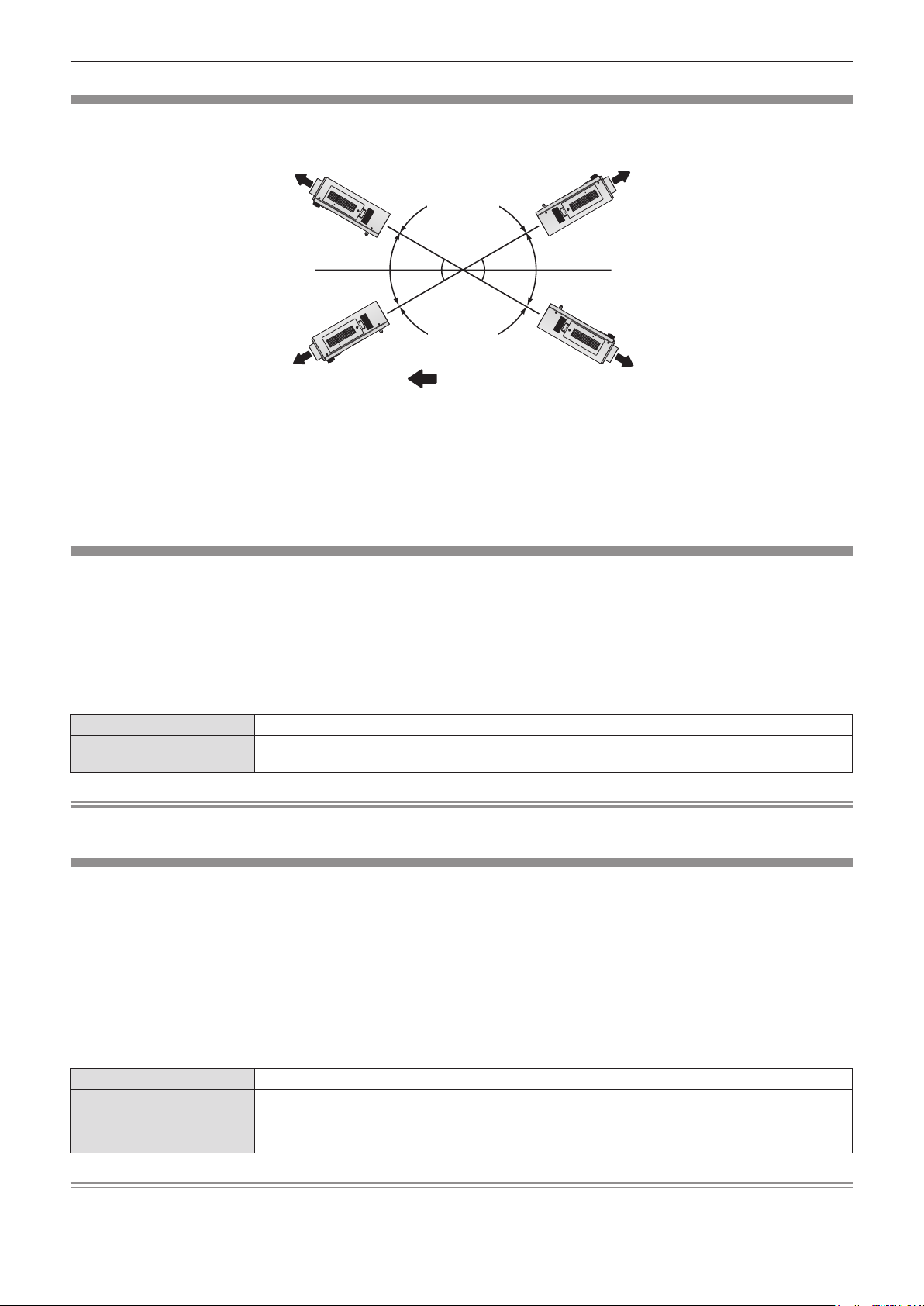
Chapter 4 Settings — [PROJECTOR SETUP] menu
3URMHFWLRQGLUHFWLRQ
[COOLING CONDITION]
Change the fan control depending on the direction of projection.
Set [COOLING CONDITION] correctly in accordance with the direction of projection referring to the following gure. It may shorten the life of
the lamp if used in incorrect setting.
>83:$5'
6(77,1*@
>)/2256(77,1*@
Press as to select [COOLING CONDITION].
1)
Press the <ENTER> button.
2)
The [COOLING CONDITION] screen is displayed.
rf
>'2:1:$5
'6(77,1*@
:
Press as to select a cooling condition.
3)
Press the <ENTER> button.
4)
When the confirmation is displayed, select [OK]
5)
or [CANCEL], and press the <ENTER> button.
[HIGH ALTITUDE MODE]
Set to [ON] to use the projector at 1 400 m (4 593 ft) to 2 700 m (8 858 ft) elevations.
Press as to select [HIGH ALTITUDE MODE].
1)
Press qw to switch [HIGH ALTITUDE MODE].
2)
The setting will change between [OFF] and [ON].
rf
[HIGH ALTITUDE MODE]
rr
When the confirmation is displayed, select [OK]
3)
or [CANCEL], and press the <ENTER> button.
>&(,/,1*6(77,1*@
[OFF] When using at a place lower than 1 400 m (4 593 ft) above sea level
[ON]
When using at a high altitude (1 400 m (4 593 ft) or higher and lower than 2 700 m (8 858 ft) above sea
level)
Note
The speed of the fan increases and the operation sound becomes louder when set to [ON].
rf
[LAMP SELECT]
Switch between brightness of two lamps and that of single lamp from the two luminous lamps built into the projector body according to the
use condition or purpose. When [SINGLE] is set, the lamp to be turned on is automatically selected based on the cumulative operating time of
lamps.
Press as to select [LAMP SELECT].
1)
[LAMP SELECT]
rr
[DUAL] Two lamps will light.
[SINGLE] Single lamp will light. (The lamp with shorter cumulative operating time is selected automatically.)
[LAMP1] Lamp 1 will light.
[LAMP2] Lamp 2 will light.
Press qw to switch [LAMP SELECT].
2)
The setting will change among [DUAL], [SINGLE], [LAMP1] and
rf
[LAMP2] each time you press the button.
Press the <ENTER> button.
3)
Note
When [SINGLE], [LAMP1], or [LAMP2] is selected, if the lamp does not light or the cumulative operating time exceeds 2 500 hours (when
rf
[LAMP POWER] is set to [NORMAL]), the other lamp will light. When [DUAL] is selected, if either lamp does not light or the cumulative
76 - ENGLISH
Page 77

Chapter 4 Settings — [PROJECTOR SETUP] menu
operating time of either of them exceeds 2 500 hours (when [LAMP POWER] is set to [NORMAL]), only the other lamp will light. However, if
both lamps do not light, or the cumulative operating time of both of them exceeds 2 500 hours (when [LAMP POWER] is set to [NORMAL]),
the projector will go into standby.
The font colors of the items indicate the status.
rf
Green → Current setting
Yellow → Current setting (when there is a lamp that cannot turn on or failed to turn on)
Red → Lamp that has failed to turn on
White → Any other status
Repeatedly switching in a short time will increase the speed of the lamp replacement cycle.
rf
[LAMP RELAY]
The lamp to be turned on can be automatically switched by specifying the day of the week and time.
The degradation of the lamp due to continuous usage can be reduced by automatically switching the lamp to be turned on when using the
projector continuously for 1 week or more.
Press as to select [LAMP RELAY].
1)
Press qw to switch [LAMP RELAY].
2)
The setting will change among [OFF], [24H], and [1WEEK] each
rf
time you press the button.
Press as to select [TIME].
3)
Press the <ENTER> button.
4)
Enters adjustment mode (the display is blinking).
rf
[LAMP RELAY]
rr
[OFF] Disables lamp relay.
[24H] Switches lamps on a day-to-day basis.
[1WEEK] Switches lamps on a week-to-week basis.
[DAY OF THE WEEK]
rr
[SUNDAY]
[MONDAY]
[TUESDAY]
[WEDNESDAY]
[THURSDAY]
[FRIDAY]
[SATURDAY]
The lamp to be turned on will be switched automatically on the set day of the week.
Press qw to select [HOUR] or [MINUTE], and
5)
then press as to adjust it.
Hours only can be adjusted with one hour increments when
rf
[HOUR] is selected and minutes only can be adjusted with
one minute increments between 00 and 59 when [MINUTE] is
selected.
Press the <ENTER> button.
6)
The adjusted time is established.
rf
Press as to select [DAY OF THE WEEK].
7)
Press qw to switch [DAY OF THE WEEK].
8)
The setting will change among [SUNDAY], [MONDAY],
rf
[TUESDAY], [WEDNESDAY], [THURSDAY], [FRIDAY] and
[SATURDAY] each time you press the button.
Note
The [LAMP RELAY] function is enabled when [DUAL] or [SINGLE] is selected in [LAMP SELECT].
rf
Only a single lamp lights for four hours from the preset time when [DUAL] is selected in [LAMP SELECT].
rf
The operating time will be the local time. (x page 83)
rf
Use the number (<0> to <9>) buttons on the remote control to directly enter the time.
rf
[LAMP POWER]
Switch lamp brightness according to the operating environment or purpose of the projector.
Press as to select [LAMP POWER].
1)
[LAMP POWER]
rr
[NORMAL] Set when high luminance is required.
Press qw to switch [LAMP POWER].
2)
The setting will change between [NORMAL] and [ECO] each
rf
time you press the button.
ENGLISH - 77
Page 78

Chapter 4 Settings — [PROJECTOR SETUP] menu
[ECO] Set when high luminance is not required.
Note
When [ECO] is set, the power consumption and operation sound can be reduced while the lamp life can be increased.
rf
[STANDBY MODE]
Set the power consumption during the standby.
Press as to select [STANDBY MODE].
1)
[STANDBY MODE]
rr
[NORMAL] Normally use this setting.
[ECO] Use this setting to reduce power consumption during standby.
Press qw to switch [STANDBY MODE].
2)
The setting will change between [NORMAL] and [ECO] each
rf
time you press the button.
Note
When set to [ECO], network functions and <SERIAL OUT> terminal are not available during standby. Also, some RS-232C commands are
rf
not available. When set to [NORMAL], network functions and <SERIAL OUT> terminal are available during standby.
If set to [ECO], there may be a time lag of approximately 10 seconds between turning on the power and starting projection compared to
rf
when the setting is [NORMAL].
[SCHEDULE]
Set the command execution schedule for each day of the week.
Enabling/disabling the schedule function
Press as to select [SCHEDULE].
1)
[SCHEDULE]
rr
Press qw to switch [SCHEDULE].
2)
The setting will change between [OFF] and [ON] each time you
rf
press the button.
[OFF] Disables the schedule function.
[ON]
Enables the schedule function. Refer to “How to assign a program” (x page 78) or “How to set a
program” (x page 78) in regard to how to set the schedule.
Note
When [SCHEDULE] is set to [ON], the [STANDBY MODE] setting is forcibly switched to [NORMAL], and the setting cannot be changed.
rf
Even if [SCHEDULE] is then set to [OFF] when in this state, the setting of [STANDBY MODE] remains at [NORMAL].
How to assign a program
Press as to select [SCHEDULE].
1)
Press qw to select [ON], and press the
2)
<ENTER> button.
The [SCHEDULE] screen is displayed.
rf
Select and assign program to each day of
3)
week.
Press as to select the day of week, and press qw to select a
rf
program number.
You can set the program from No.1 to No.7. “- - -” indicates that
rf
the program number has not been set yet.
How to set a program
You can set up to 16 commands to each program.
Press as to select [SCHEDULE].
1)
Press qw to select [ON], and press the
2)
<ENTER> button.
The [SCHEDULE] screen is displayed.
rf
Press as to select [PROGRAM EDIT].
3)
Press qw to select a program number and
4)
then press the <ENTER> button.
Press as to select a command number and
5)
press the <ENTER> button.
You can change the page using qw.
rf
Press as to select [TIME], and press the
6)
<ENTER> button.
78 - ENGLISH
Page 79

Chapter 4 Settings — [PROJECTOR SETUP] menu
Press qw to select hour and minute, and press
7)
as or the number (<0> to <9>) buttons to set
a time, and press the <ENTER> button.
Press as to select [COMMAND].
8)
Press qw to switch [COMMAND].
9)
The setting will change among [POWER ON], [STANDBY],
rf
[SHUTTER]
and [SIDE BY SIDE]
*1 The details set in step 11) are displayed.
*2 Only for PT-DW640E
Press the <ENTER> button.
10)
The [COMMAND] detailed screen is displayed.
rf
[COMMAND]
rr
[LAMP SELECT]
* Only for PT-DW640E
*1
, [INPUT]*1, [LAMP SELECT]*1, [LAMP POWER]*1
*1*2
each time you press the button.
[POWER ON] ― Turns the power on.
[STANDBY] ― Enters standby.
[SHUTTER]
[INPUT]
[LAMP POWER]
[SIDE BY SIDE]
*
[OPEN] Opens the shutter.
[CLOSE] Closes the shutter.
[RGB1] Switches the input to RGB1.
[RGB2] Switches the input to RGB2.
[VIDEO] Switches the input to VIDEO.
[S-VIDEO] Switches the input to S-VIDEO.
[DVI-D] Switches the input to DVI-D.
[HDMI] Switches the input to HDMI.
[DUAL] Turns on both lamps.
[SINGLE]
[NORMAL] Sets the high luminance of the lamp.
[ECO] Sets lower luminance of the lamp than [NORMAL].
[OFF] Displays the side-by-side screen.
[ON] Cancels the side-by-side screen.
Note
Press as to select a command.
11)
[OPEN]/[CLOSE] in [SHUTTER], [RGB1]/[RGB2]/[VIDEO]/
rf
[S-VIDEO]/[DVI-D]/[HDMI] in [INPUT], [DUAL]/[SINGLE] in
[LAMP SELECT], [NORMAL]/[ECO] in [LAMP POWER], and
[OFF]/[ON] in [SIDE BY SIDE] will change each time you press
.
qw
Press the <ENTER> button.
12)
The command is xed and ● is displayed at the left of the
rf
selected command.
After the command is xed, press the <MENU> button to close
rf
the detailed setting menu.
Press as to select [STORE], and press the
13)
<ENTER> button.
Turns on one lamp. (The lamp is automatically selected which has shorter
cumulative operating time.)
If you try to register a setting that would cause the lamp to ash for a short time, an error message will be displayed on the screen. Set the
rf
time and command again.
To delete a command already set, press the <DEFAULT> button on the Step 5) screen, or select [DELETE] on the Step 6) screen and press
rf
the <ENTER> button.
If multiple commands have been set for the same time, they are executed in chronological order starting from the smallest command
rf
number.
The operating time will be the local time. (x page 83)
rf
If an operation is executed with the remote control or control panel of the projector or with a control command before the command set in
rf
[SCHEDULE] is executed, the command set with this function may not be executed.
[STARTUP INPUT SELECT]
Set the input signal to be projected when the projector is switched on.
Press as to select [STARTUP INPUT
1)
SELECT].
[STARTUP INPUT SELECT]
rr
[LAST USED] Keeps the input selected last.
[RGB1] Sets the input to be projected when the projector is switched on to RGB1.
[RGB2] Sets the input to be projected when the projector is switched on to RGB2.
[VIDEO] Sets the input to be projected when the projector is switched on to VIDEO.
Press qw to switch [STARTUP INPUT
2)
SELECT].
The setting will change among [LAST USED], [RGB1], [RGB2],
rf
[VIDEO], [S-VIDEO], [DVI-D] and [HDMI] each time you press
the button.
ENGLISH - 79
Page 80

Chapter 4 Settings — [PROJECTOR SETUP] menu
[S-VIDEO] Sets the input to be projected when the projector is switched on to S-VIDEO.
[DVI-D] Sets the input to be projected when the projector is switched on to DVI-D.
[HDMI] Sets the input to be projected when the projector is switched on to HDMI.
[RS-232C]
Set the communication conditions of the <SERIAL IN>/<SERIAL OUT> terminal.
To set the communication condition of the <SERIAL IN> terminal
Press as to select [RS-232C].
1)
Press the <ENTER> button.
2)
The [RS-232C] screen is displayed.
rf
Press as to select [(IN) BAUDRATE].
3)
[(IN) BAUDRATE]
rr
[9600]
Select the proper speed.[19200]
[38400]
[(IN) PARITY]
rr
[NONE]
Select the parity condition.[EVEN]
[ODD]
Press qw to switch [(IN) BAUDRATE].
4)
The setting will change among [9600], [19200], and [38400]
rf
each time you press the button.
Press as to select [(IN) PARITY].
5)
Press qw to switch [(IN) PARITY].
6)
The setting will change among [NONE], [EVEN], and [ODD]
rf
each time you press the button.
To set the communication condition of the <SERIAL OUT> terminal
Press as to select [RS-232C].
1)
Press the <ENTER> button.
2)
The [RS-232C] screen is displayed.
rf
Press as to select [(OUT) BAUDRATE].
3)
Press qw to switch [(OUT) BAUDRATE].
4)
The setting will change among [9600], [19200], and [38400]
rf
each time you press the button.
Press as to select [(OUT) PARITY].
5)
Press qw to switch [(OUT) PARITY].
6)
The setting will change among [NONE], [EVEN], and [ODD]
rf
each time you press the button.
[(OUT) BAUDRATE]
rr
[9600]
Select the proper speed.[19200]
[38400]
[(OUT) PARITY]
rr
[NONE]
Select the parity condition.[EVEN]
[ODD]
To set the response
Press as to select [RS-232C].
1)
Press the <ENTER> button.
2)
The [RS-232C] screen is displayed.
rf
Press as to select [RESPONSE(ID ALL)].
3)
80 - ENGLISH
Press qw to switch [RESPONSE(ID ALL)].
4)
The setting will change between [ON] and [OFF] each time you
rf
press the button.
Press as to select [GROUP].
5)
Page 81

Chapter 4 Settings — [PROJECTOR SETUP] menu
Press qw to switch [GROUP].
6)
The setting will change among [A] to [Z] each time you press
rf
the button.
Press as to select [RESPONSE(ID GROUP)].
7)
[RESPONSE(ID ALL)]
rr
[ON] Returns the response when the ID setting is ALL.
[OFF] Does not return the response when the ID setting is ALL.
[GROUP]
rr
[A] - [Z]
[RESPONSE(ID GROUP)]
rr
[ON] Returns the response when the ID setting is GROUP.
[OFF] Does not return the response when the ID setting is GROUP.
Controls multiple projectors simultaneously by sending the ID of RS-232C.
Set the group from [A] to [Z]. The projector responds when the ID of RS-232C matches the setting.
Note
Refer to “<SERIAL IN>/<SERIAL OUT> terminal” (x page 121).
rf
[REMOTE2 MODE]
Press qw to switch [RESPONSE(ID GROUP)].
8)
The setting will change between [ON] and [OFF] each time you
rf
press the button.
You can set the <REMOTE 2 IN> terminal.
Press as to select [REMOTE2 MODE].
1)
Press qw to switch [REMOTE2 MODE].
2)
The setting will change between [DEFAULT] and [USER] each
rf
time you press the button.
When [USER] is selected, proceed to Step 3).
rf
[REMOTE2 MODE]
rr
[DEFAULT]
[USER]
The pin assignment of the <REMOTE 2 IN> terminal is used by the factory default setting of the projector.
(x page 124)
The pin assignment of the <REMOTE 2 IN> terminal is used by the setting changed from the factory default
setting of the projector.
[STATUS]
Displays the status of the projector.
Press as to select [STATUS].
1)
Press the <ENTER> button.
2)
The [STATUS] screen is displayed.
rf
Contents to be displayed
rr
Press the <ENTER> button.
3)
Press as to select any from [PIN2] to [PIN8]
4)
and press qw to switch the setting.
[PIN1] and [PIN9] cannot be changed.
rf
Press qw to switch the pages.
3)
The page will change each time you press the button.
rf
[INPUT] Displays the input terminal currently selected.
[SIGNAL NAME] Displays the input signal name.
[SIGNAL FREQUENCY] Displays the frequency of the input signal.
[PROJECTOR RUNTIME] Displays the operation times of the projector.
[LAMP1]
[LAMP2]
[INTAKE AIR TEMP.] Displays the status of the air intake temperature of the projector.
[OPTICS MODULE TEMP.] Displays the status of the internal temperature of the projector.
[AROUND LAMP TEMP.] Displays the status of the temperature around the lamps of the projector.
[PROJECTOR TYPE] Displays the type of the projector.
[SERIAL NUMBER] Displays the serial number of the projector.
[LAMP UNIT MODEL NO.] Displays the model no. of the lamp unit.
*
*
Displays the hours used of lamp 1.
Displays the hours used of lamp 2.
ENGLISH - 81
Page 82

Chapter 4 Settings — [PROJECTOR SETUP] menu
[LAMP1 SERIAL NUMBER] Displays the serial number of the lamp 1.
[LAMP2 SERIAL NUMBER] Displays the serial number of the lamp 2.
[MAIN VERSION] Displays the main version of the rmware of the projector.
[SUB VERSION] Displays the sub version of the rmware of the projector.
[NETWORK VERSION] Displays the network version of the projector.
[POWER ON TIMES] Displays the number of times the power is turned on.
[ON COUNT]
[LAMP1] Displays the details of cumulative operating time.
[LAMP2] Displays the details of cumulative operating time.
[NUMBER OF ENTRY SIGNAL] Displays the number of registered signals.
[REMOTE2 STATUS] Displays the control status of the REMOTE2.
[SIGNAL INFORMATION]
* Displays the actual time for the hours used of lamp.
To calculate a rough guide for lamp replacement, convert as follows:
[LAMP1 ON] Displays the number of times lamp 1 has been turned on.
[LAMP2 ON] Displays the number of times lamp 2 has been turned on.
[SHUTTER] Displays the number of times the shutter function has been used.
[MEMORY NO.] Displays the memory number of the input signal.
[INPUT] Displays the input terminal currently selected.
[SIGNAL NAME] Displays the input signal name.
[SIGNAL FREQUENCY] Displays the frequency of the input signal.
[SYNC.STATE] Displays the synch polarity of the input signal.
[V.SYNC WIDTH] Displays the vertical sync signal pulse width of the input signal.
[SCAN TYPE] Displays the scan type of the input signal.
[TOTAL DOTS] Displays the total dot count of the input signal.
[DISPLAY DOTS] Displays the number of input signal display dots.
[TOTAL LINES] Displays the total line count of the input signal.
[DISPLAY LINES] Displays the number of input signal display lines.
[SAMPLING] Displays the sampling information of the input signal.
Lamp replacement time =
Cumulative operating time when [LAMP POWER] is set to [NORMAL] + (Cumulative operating time when [LAMP POWER] is set to [ECO] x
5/6)
Note
The content of status can be sent via E-mail by pressing the <ENTER> button while displaying the status.
rf
Some items in [SIGNAL INFORMATION] may be displayed and others not displayed, depending on the signal being input.
rf
The “lighting time” and “usage time” of the lamp displayed in [STATUS] may differ from the actual time if the lamp unit that has been used on
rf
other models than this projector (PT-DW640E/PT-DX610E) is attached and used on the projector, or if the lamp unit that has been used on
this projector (PT-DW640E/PT-DX610E) is attached and used on other projector models.
[NO SIGNAL SHUT-OFF]
You can set the power of the projector automatically to standby if there is no input signal by the specied time.
Press as to select [NO SIGNAL SHUT-OFF].
1)
[NO SIGNAL SHUT-OFF]
rr
[DISABLE] Disables the No signal shut-off function.
[10MIN.] - [90MIN.] Allows you to set in ten minutes intervals.
Press qw to switch [NO SIGNAL SHUT-OFF].
2)
[FUNCTION BUTTON]
Set the functions of the <FUNCTION> button on the remote control.
Press as to select [FUNCTION BUTTON].
1)
Press as to select a function.
3)
Press the <ENTER> button.
2)
The [FUNCTION BUTTON] screen is displayed.
rf
Available functions
rr
[DISABLE] Disables the <FUNCTION> button.
82 - ENGLISH
Press the <ENTER> button.
4)
Page 83

Chapter 4 Settings — [PROJECTOR SETUP] menu
[SUB MEMORY] Switches the sub memory. (x page 87)
[SYSTEM SELECTOR] Switches the [SYSTEM SELECTOR] setting. (x page 59)
[SYSTEM DAYLIGHT VIEW] Switches the [SYSTEM DAYLIGHT VIEW] setting. (x page 57)
[FREEZE] Temporarily freezes video to be a still image. (x page 73)
[SIDE BY SIDE]
* Only for PT-DW640E
*
Switches to the two window display. (x page 73)
[DATE AND TIME]
Set the time zone, date, and time of the built-in clock of the projector.
To set time zone
Press as to select [DATE AND TIME].
1)
Press the <ENTER> button.
2)
The [DATE AND TIME] screen is displayed.
rf
To set the date and time manually
Press as to select [DATE AND TIME].
1)
Press the <ENTER> button.
2)
The [DATE AND TIME] screen is displayed.
rf
Press as to select [ADJUST CLOCK].
3)
Press the <ENTER> button.
4)
The [ADJUST CLOCK] screen is displayed.
rf
To set the date and time automatically
Press as to select [DATE AND TIME].
1)
Press the <ENTER> button.
2)
The [DATE AND TIME] screen is displayed.
rf
Press as to select [ADJUST CLOCK].
3)
Press the <ENTER> button.
4)
The [ADJUST CLOCK] screen is displayed.
rf
Press as to select [TIME ZONE].
3)
Press qw to switch [TIME ZONE].
4)
Press as to select an item, and press qw to
5)
set the local date and time.
Press as to select [APPLY], and press the
6)
<ENTER> button.
The setting of the time will be completed.
rf
Press as to select [NTP SYNCHRONIZATION],
5)
and press qw to change the setting to [ON].
The setting will change between [ON] and [OFF] each time you
rf
press the button.
Press as to select [APPLY], and press the
6)
<ENTER> button.
The setting of the time will be completed.
rf
[NTP SYNCHRONIZATION]
rr
[ON] Enables [NTP SYNCHRONIZATION].
[OFF] Disables [NTP SYNCHRONIZATION].
Note
To set the date and time automatically, the projector must be connected to the network.
rf
If synchronization with the NTP server fails just after [NTP SYNCHRONIZATION] is turned [ON], or if [NTP SYNCHRONIZATION] is turned
rf
[ON] while the NTP server is not set, [NTP SYNCHRONIZATION] will return to [OFF].
Access the projector via a web browser to set the NTP server. Refer to “[Adjust clock] page” (x page 99) for details.
rf
[SAVE ALL USER DATA]
Save the various setting values as a backup in the built-in memory of the projector.
Press as to select [SAVE ALL USER DATA].
1)
When the confirmation is displayed, select [OK]
4)
or [CANCEL], and press the <ENTER> button.
Press the <ENTER> button.
2)
The [SECURITY PASSWORD] screen is displayed.
rf
Enter a security password and press the
3)
[PROGRESS] is displayed while saving data.
rf
<ENTER> button.
ENGLISH - 83
Page 84

Chapter 4 Settings — [PROJECTOR SETUP] menu
Note
The image setting registered in [USER LOGO] is not saved.
rf
[LOAD ALL USER DATA]
Load the various setting values saved as a backup in the built-in memory of the projector.
Press as to select [LOAD ALL USER DATA].
1)
Enter a security password and press the
3)
<ENTER> button.
Press the <ENTER> button.
2)
When the confirmation is displayed, select [OK]
The [SECURITY PASSWORD] screen is displayed.
rf
4)
or [CANCEL], and press the <ENTER> button.
Note
The projector will go into the standby status to reect the setting values when [LOAD ALL USER DATA] is executed.
rf
[INITIALIZE]
Return various setting values to their factory default settings.
Press as to select [INITIALIZE].
1)
Press the <ENTER> button.
2)
The [SECURITY PASSWORD] screen is displayed.
rf
Enter a security password and press the
3)
<ENTER> button.
The [INITIALIZE] screen is displayed.
rf
Items that can be initialized
rr
All setting items including [ENTRY SIGNAL], [NETWORK SETUP], [E-mail set up], and [USER LOGO] are
[ALL USER DATA]
[ENTRY SIGNAL]
[NETWORK/E-MAIL] Returns [NETWORK SETUP] and [E-mail set up] to factory default settings.
[LOGO IMAGE] Deletes the image registered in [USER LOGO].
returned to factory default values.
The projector will go into the standby status to reect the setting values.
Deletes all the setting values saved for each input signal.
To delete only a part of a registered signal, perform the procedure described in “Deleting the registered
data” (x page 86).
Press as to select an item to initialize.
4)
Press the <ENTER> button.
5)
When the confirmation is displayed, select [OK]
6)
or [CANCEL], and press the <ENTER> button.
[SERVICE PASSWORD]
Used by a service person.
84 - ENGLISH
Page 85

Chapter 4 Settings — [TEST PATTERN] menu
[TEST PATTERN] menu
Select [TEST PATTERN] from the main menu.
Refer to “Navigating through the menu” (x page 51) for the operation of the menu screen.
Press qw to switch.
rf
[TEST PATTERN]
Displays the test pattern built-in to the projector.
Settings of position, size, and other factors will not be reected in test patterns. Make sure to display the input signal before performing various
adjustments.
Press qw to switch [TEST PATTERN].
1)
The setting will change among “Menu screen + Focus”, “Menu
rf
screen + Entry screen”*, “Menu screen + All white”, “Menu
screen + All black”, “Menu screen + Flag”, “Menu screen + Flag
(inversion)”, “Menu screen + Window”, “Menu screen + Window
(inversion)”, “Menu screen + Color bar (vertical)”, and “Menu
screen + Color bar (horizontal)” each time you press the button.
* The test pattern built-in to the projector is not being displayed.
[TEST PATTERN]
rr
Menu screen + Focus
Menu screen + Entry screen
Menu screen + All white
Menu screen + All black
Menu screen + Flag
Menu screen + Flag (inversion)
Menu screen + Window
Menu screen + Window (inversion)
Menu screen + Color bar (vertical)
Menu screen + Color bar (horizontal)
Displays a test pattern with the menu screen. Select a test pattern so that it is easy to
make various adjustments.
Note
Press the <ON SCREEN> button on the remote control while the test pattern is displayed to hide the menu screen.
rf
ENGLISH - 85
Page 86

Chapter 4 Settings — [SIGNAL LIST] menu
$
[SIGNAL LIST] menu
Select [SIGNAL LIST] from the main menu.
Refer to “Navigating through the menu” (x page 51) for the operation of the menu screen.
Registered signal status
rr
A name can be set for each sub memory (x page 87).
rf
Memory number:
rf
6XEPHPRU\QXPEHU
:KHQWKHDGGUHVVQXPEHU$$+
+LVUHJLVWHUHG
Registering a signal to the list
After a new signal is input and the <MENU> button on the remote control or the control panel is pressed, the registration is completed and the
[MAIN MENU] screen is displayed.
Note
Up to 96 signals, including sub memories, can be registered to the projector.
rf
There are 12 pages (eight memories of A through L, with eight memories possible on each page) for memory numbers, and it is registered to
rf
the lowest number that is available. If there is no available memory number it will be overwritten from the oldest signal.
The names to be registered are automatically determined by the input signals and memory numbers.
rf
If a menu is being displayed, the new signals will be registered at the instant they are input.
rf
Renaming the registered data
Registered signals can be renamed.
Press asqw to select the signal for which
1)
details are to be displayed.
Press the <ENTER> button.
2)
The [REGISTERED SIGNAL STATUS] screen is displayed.
rf
The memory number, input terminal, input signal name,
rf
frequency, synchronization signal, etc., are displayed.
Press the <MENU> button to return to the [REGISTERED
rf
SIGNAL LIST] screen.
Press the <ENTER> button.
3)
The [REGISTERED SIGNAL SETUP] screen is displayed.
rf
Press as to select [SIGNAL NAME CHANGE].
4)
Press the <ENTER> button.
5)
The [SIGNAL NAME CHANGE] screen is displayed.
rf
Press asqw to select the text, and press the
6)
<ENTER> button to enter the text.
After the name is changed, press asqw to
7)
select [OK], and press the <ENTER> button.
The registration is completed and it will return to the
rf
[REGISTERED SIGNAL SETUP] screen.
When pressing
rf
the <ENTER> button, the changed signal name will not be
registered and an automatically registered signal name will be
used.
asqw
to select [CANCEL] and pressing
Deleting the registered data
Registered signals can be deleted.
Press asqw to select the signal to delete.
1)
Press the <DEFAULT> button.
2)
The [ENTRY SIGNAL DELETE] screen is displayed.
rf
To cancel the deletion, press the <MENU> button to return to
rf
the [REGISTERED SIGNAL LIST] screen.
86 - ENGLISH
Press the <ENTER> button.
3)
The selected signal will be deleted.
rf
Page 87

Chapter 4 Settings — [SIGNAL LIST] menu
Note
A signal can also be deleted from [ENTRY SIGNAL DELETE] on the [REGISTERED SIGNAL SETUP] screen.
rf
Protecting the registered data
Registered signals can be protected.
Press asqw to select the signal to protect.
1)
Press the <ENTER> button.
2)
The [REGISTERED SIGNAL STATUS] screen is displayed.
rf
Press the <ENTER> button.
3)
The [REGISTERED SIGNAL SETUP] screen is displayed.
rf
[LOCK]
rr
[OFF] The signal is not protected.
[ON] The signal is protected.
Press as to select [LOCK].
4)
Press qw to switch [LOCK].
5)
The setting will change between [OFF] and [ON] each time you
rf
press the button.
Note
When [LOCK] is set to [ON], signal delete, image adjustment and auto setup are not available. To perform these operations, set [LOCK] to
rf
[OFF].
A signal can be registered to sub memory even if it is protected.
rf
Even a protected signal will be deleted if [INITIALIZE] is executed.
rf
Expanding signal lock-in range
Signal lock-in range can be expanded.
Press asqw to select the signal to set.
1)
Press the <ENTER> button.
2)
The [REGISTERED SIGNAL STATUS] screen is displayed.
rf
Press the <ENTER> button.
3)
The [REGISTERED SIGNAL SETUP] screen is displayed.
rf
Press as to select [LOCK-IN RANGE].
4)
Press qw to switch [LOCK-IN RANGE].
5)
The setting will change between [NARROW] and [WIDE] each
rf
time you press the button.
[LOCK-IN RANGE]
rr
[NARROW] Select in most cases.
[WIDE] Widens the lock-in range.
Note
Switch the range that determines that a signal to be input is the same signal that is already registered.
rf
To prioritize the determination that it is the same signal that is already registered, set to the [WIDE] setting.
rf
Use in cases such as when the synchronizing frequency of a signal to be input has changed slightly, or multiple signal lists are registered.
rf
Can only be used when a signal is input from the <RGB 1 IN> terminal, <RGB 2 IN> terminal, <DVI-D IN> terminal, or <HDMI IN> terminal.
rf
When [WIDE] is set, the image may appear distorted because a signal is determined to be the same signal even if a synchronizing
rf
frequency changes slightly.
When a signal to be input corresponds to the signal set in [WIDE], a registered signal with a high memory number receives priority.
rf
Example: A signal to be input that corresponds to memory numbers A2, A4 and B1 will be determined to be B1.
When a registration signal is deleted, the settings are also deleted.
rf
In an environment where multiple types of signals are input to the same terminal, signals are sometimes not determined correctly when
rf
settings are set to [WIDE].
Managing the sub memory list
The projector has a sub memory function that can register the multiple image adjustment data, even if it is recognized as the same signal by
the frequency or format of the synchronization signal source.
Use this function when you need to adjust the picture quality such as switching of the aspect ratio or white balance by the same
synchronization signal source. The sub memory includes all the data that can be adjusted for each signal, such as the screen aspect ratio and
data adjusted in the [PICTURE] item ([CONTRAST], [BRIGHTNESS], etc.).
ENGLISH - 87
Page 88

Chapter 4 Settings — [SIGNAL LIST] menu
To register the current settings to the list
Press qw on the normal screen (when the
1)
menu is not displayed).
The sub memory registration screen is displayed if the sub
rf
memory is not registered. Proceed to Step 3).
A list of sub memories registered to the signal currently input is
rf
displayed.
When [SUB MEMORY] is selected with [PROJECTOR SETUP]
rf
→ [FUNCTION BUTTON] on the menu, the <FUNCTION>
button can be used instead of qw.
To switch to the sub memory list
Press qw on the normal screen (when the
1)
menu is not displayed).
A list of sub memories registered to the signal currently input is
rf
displayed.
To delete the sub memory data
Press qw on the normal screen (when the
1)
menu is not displayed).
The [SUB MEMORY LIST] screen is displayed.
rf
Press asqw to select the sub memory to
2)
delete, and press the <DEFAULT> button.
The [ENTRY SIGNAL DELETE] screen is displayed.
rf
To cancel the deletion, press the <MENU> button to return to
rf
the [SUB MEMORY LIST] screen.
Press asqw to select the sub memory
2)
number to register in [SUB MEMORY LIST].
Press the <ENTER> button.
3)
The [SIGNAL NAME CHANGE] screen is displayed.
rf
Press asqw to select [OK], and press the
4)
<ENTER> button.
To rename the registered data, follow the procedure in Steps 4)
rf
and 5) in “Renaming the registered data” (x page 86).
Press asqw to select the signal to switch in
2)
[SUB MEMORY LIST].
Press the <ENTER> button.
3)
This switches to the signal selected in Step 2).
rf
Press the <ENTER> button.
3)
The selected sub memory will be deleted.
rf
88 - ENGLISH
Page 89

Chapter 4 Settings — [SECURITY] menu
[SECURITY] menu
Select [SECURITY] from the main menu, and select the item from the sub-menu.
Refer to “Navigating through the menu” (x page 51) for the operation of the menu screen.
When the projector is used for the rst time
rf
Initial password: Press
After selecting the item, press
rf
awsqawsq
asqw
Attention
When you select the [SECURITY] from the main menu and press the <ENTER> button, entering a password is required. Enter the set
rf
password and then continue operations of the [SECURITY] menu.
When the password has been changed previously, enter the changed password, and press the <ENTER> button.
rf
Note
in order, and press the <ENTER> button.
to set.
The entered password is displayed with * mark on the screen.
rf
[SECURITY PASSWORD]
The [SECURITY PASSWORD] screen is displayed when the power is turned on. When the entered password is incorrect, the operation will be
restricted to the power standby <v> button, the <SHUTTER> button, and the <LENS> (<FOCUS>, <ZOOM>, and <SHIFT>) buttons.
Press as to select [SECURITY PASSWORD].
1)
[SECURITY PASSWORD]
rr
[OFF] Disables the security password entry.
[ON] Enables the security password entry.
Press qw to switch [SECURITY PASSWORD].
2)
The setting will change between [OFF] and [ON] each time you
rf
press the button.
Note
The [SECURITY PASSWORD] setting is set to [OFF] at the time of purchase or when all the user data has been initialized.
rf
Change the password periodically that is hard to guess.
rf
The security password will be enabled after setting [SECURITY PASSWORD] to [ON] and turning the <MAIN POWER> switch to <OFF>.
rf
[SECURITY PASSWORD CHANGE]
Change the security password.
Press as to select [SECURITY PASSWORD
1)
CHANGE].
Press the <ENTER> button.
2)
The [SECURITY PASSWORD CHANGE] screen is displayed.
rf
Press asqw and the number (<0> to <9>)
3)
buttons to set the password.
Up to eight button operations can be set.
rf
Press the <ENTER> button.
4)
Re-enter the password for the confirmation.
5)
Press the <ENTER> button.
6)
Note
The entered password is displayed with * mark on the screen.
rf
An error message is displayed on the screen when the entered password is incorrect. Re-enter the correct password.
rf
[DISPLAY SETTING]
Overlap the security message (text or image) over the projecting image.
Press as to select [DISPLAY SETTING].
1)
ENGLISH - 89
Page 90

Chapter 4 Settings — [SECURITY] menu
Press qw to switch [DISPLAY SETTING].
2)
The setting will change among [OFF], [TEXT], and[USER
rf
LOGO] each time you press the button.
[DISPLAY SETTING]
rr
[OFF] The text display is disabled.
[TEXT] The text display is enabled.
[USER LOGO] The picture registered by the user is projected.
Note
To create the image for [USER LOGO], “Logo Transfer Software” included in the supplied CD-ROM is required.
rf
[TEXT CHANGE]
Change the text displayed when the text display is enabled by selecting [TEXT] in [DISPLAY SETTING].
Press as to select [TEXT CHANGE].
1)
Press asqw to select the text, and press the
3)
<ENTER> button to enter the text.
Press the <ENTER> button.
2)
The [TEXT CHANGE] screen is displayed.
rf
Maximum 22 characters can be input.
rf
Press asqw to select [OK], and press the
4)
<ENTER> button.
The text is changed.
rf
[MENU LOCK]
Display the menu with the <MENU> button, and set whether to enable menu operations.
Press as to select [MENU LOCK].
1)
[MENU LOCK]
rr
[OFF] Cancels the lock on menu operations.
[ON] Locks menu operations.
Note
After setting [MENU LOCK] to [ON], if the wrong password is input, the <MENU> button cannot be operated.
rf
At the time of purchase or after [ALL USER DATA] initialization, [MENU LOCK] is set to [OFF].
rf
The lock release is maintained until the projector enters standby.
rf
Press qw to switch [MENU LOCK].
2)
The setting will change between [OFF] and [ON] each time you
rf
press the button.
[MENU LOCK PASSWORD]
Change the menu lock password.
Press as to select [MENU LOCK
1)
PASSWORD].
Press the <ENTER> button.
2)
The [MENU LOCK PASSWORD] screen is displayed.
rf
Press asqw to select the text, and press the
3)
<ENTER> button to enter the text.
Maximum 16 characters can be input.
rf
Press asqw to select [OK] and press the
4)
<ENTER> button.
To cancel, select [CANCEL].
rf
Attention
The initial password when used for the rst time or after initializing all the user data is “AAAA”.
rf
Change the password periodically that is hard to guess.
rf
[CONTROL DEVICE SETUP]
Enable/disable the button operations on the control panel and the remote control.
Press as to select [CONTROL DEVICE
1)
SETUP].
Press the <ENTER> button.
2)
The [CONTROL DEVICE SETUP] screen is displayed.
rf
90 - ENGLISH
Page 91

Chapter 4 Settings — [SECURITY] menu
Press as to select [CONTROL PANEL] or
3)
[REMOTE CONTROL].
Press the <ENTER> button.
4)
The [CONTROL PANEL] screen or the [REMOTE CONTROL]
rf
screen is displayed.
[CONTROL PANEL] and [REMOTE CONTROL]
rr
You can set the limitation on the control from the control panel and
rf
remote control.
[ENABLE] Enables all button operations on the projector body and remote control.
[DISABLE] Disables all button operations on the projector body and remote control.
Press as to select an item, and press the
5)
<ENTER> button.
When the confirmation is displayed, select [OK]
6)
or [CANCEL], and press the <ENTER> button.
Note
When a button operation is performed on the device set to [DISABLE], the [SECURITY PASSWORD] screen is displayed.
rf
Enter the security password.
The [SECURITY PASSWORD] screen will disappear when the <MENU> button is pressed, or when there is no operation for approximately
rf
ten seconds.
If the operations of both [CONTROL PANEL] and [REMOTE CONTROL] are set to [DISABLE], the projector cannot be turned off (cannot
rf
enter standby).
When the setting has completed, the menu screen will disappear. To operate continuously, press the <MENU> button to display the main
rf
menu.
ENGLISH - 91
Page 92

Chapter 4 Settings — [NETWORK] menu
[NETWORK] menu
Select [NETWORK] from the main menu, and select the item from the sub-menu.
Refer to “Navigating through the menu” (x page 51) for the operation of the menu screen.
After selecting the item, press
rf
asqw
[NETWORK SETUP]
Perform the initial setting of the network before using the network function.
to set.
Press as to select [NETWORK SETUP].
1)
Press as to select [STORE], and press the
4)
<ENTER> button.
Press the <ENTER> button.
2)
When the confirmation is displayed, select [OK]
The [NETWORK SETUP] screen is displayed.
rf
5)
or [CANCEL], and press the <ENTER> button.
Press as to select an item, and change
3)
the settings according to the operation
instructions of the menu.
[NETWORK SETUP]
rr
[PROJECTOR NAME] Change the setting when using a DHCP server.
[DHCP]
[IP ADDRESS] Enter the IP address when not using a DHCP server.
[SUBNET MASK] Enter the subnet mask when not using a DHCP server.
[DEFAULT GATEWAY] Enter the default gateway address when not using a DHCP server.
[STORE] Save the current network settings.
Set the item to [ON] when using a DHCP server to automatically acquire the IP address. Set to [OFF] when
not using a DHCP server.
Note
When using a DHCP server, conrm that the DHCP server is running.
rf
Consult your network administrator regarding the IP address, subnet mask, and default gateway.
rf
[NETWORK CONTROL]
Set up the control method of the network.
Press as to select [NETWORK CONTROL].
1)
Press the <ENTER> button.
2)
The [NETWORK CONTROL] screen is displayed.
rf
Press as to select an item, then press qw to
3)
change the setting.
92 - ENGLISH
Press as to select [STORE], and press the
4)
<ENTER> button.
When the confirmation is displayed, select [OK]
5)
or [CANCEL], and press the <ENTER> button.
Page 93

Chapter 4 Settings — [NETWORK] menu
&RPSXWHU
[NETWORK CONTROL]
rr
[WEB CONTROL] Set to [ON] to control with the Web browser.
[PJLink CONTROL] Set to [ON] to control with the PJLink protocol.
Set to [ON] to control with the <SERIAL IN>/<SERIAL OUT> terminal control command format
[COMMAND CONTROL]
[COMMAND PORT] Set the port number used for command control.
[CRESTRON RoomView] Set to [ON] to control with RoomView of Crestron.
[AMX D.D.] Set to [ON] to control with the controller of AMX.
[STORE] Save the current network control settings.
(x page 123).
Refer to “Control commands via LAN” (x page 119).
[NETWORK STATUS]
Displays the status of the projector network.
Press as to select [NETWORK STATUS].
1)
Press the <ENTER> button.
2)
The [NETWORK STATUS] screen is displayed.
rf
Network connections
The projector has a network function, and the following operations are available from the computer using the Web control.
Setting and adjustment of the projector
rf
Display of the projector status
rf
Sending of E-mail messages when there is a problem with the projector
rf
“Crestron RoomView” is a system of Crestron Electronics, Inc. that manages and controls devices on multiple systems connected to a network
collectively with a computer.
The projector supports the following application software of Crestron Electronics, Inc.
RoomView Express
g
Fusion RV
g
RoomView Server Edition
g
For details of “Crestron RoomView”, refer to the website of Crestron Electronics, Inc. (English only)
rf
URL http://www.crestron.com
For the download of “RoomView Express”, also refer to the website of Crestron Electronics, Inc. (English only)
URL http://www.crestron.com/getroomview
Attention
Connect the LAN to indoor devices.
rf
Note
A LAN cable is required to use the network function.
rf
3URMHFWRU
/$1FDEOHVWUDLJKW /$1FDEOHVWUDLJKW
A Web browser is required to use this function. Conrm that the Web browser can be used beforehand.
rf
Compatible OS: Windows XP/Windows Vista/Windows 7, Mac OS X v10.4/v10.5/v10.6/v10.7
Compatible browser: Internet Explorer 7.0/8.0/9.0, Safari 4.0/5.0 (Mac OS)
Communication with an E-mail server is required to use the E-mail function. Conrm that the E-mail can be used beforehand.
rf
Use a LAN cable that is straight-through and compatible with category 5 or higher.
rf
Use a LAN cable of 100 m (328'1") or shorter length.
rf
+XE
ENGLISH - 93
Page 94

Chapter 4 Settings — [NETWORK] menu
Name and function of network function parts
1 2 3
1 LAN10/100 lamp (yellow)
Lights on when connected to the 100BASE-TX.
2 <LAN> terminal (10BASE-T/100BASE-TX)
Used to connect the LAN cable here.
Accessing from the Web browser
Start up the Web browser on the computer.
1)
Enter the IP address set on the projector into
2)
the URL entry field of the Web browser.
Enter the user name and the password.
3)
The factory default setting of the user name is user1 (user
rf
rights)/admin1 (administrator rights) and the password is
panasonic (lower case).
3 LAN LINK/ACT lamp (green)
Lights on when connected.
Flashes when transmitting/receiving data.
Click OK.
4)
The [Projector status] page is displayed.
rf
Note
If you use a Web browser to control the projector, set [WEB CONTROL] to [ON] in [NETWORK CONTROL] (x page 92).
rf
Do not perform setting or control simultaneously by starting up multiple Web browsers. Do not set or control the projector from multiple
rf
computers.
Change the password rst. (x page 104)
rf
The administrator rights allows to use all functions. The user rights allow use of [Projector status] (x page 95), conrmation of the error
rf
information page (x page 96), [Network status] (x page 97), [Basic control] (x page 98), and [Change password] (x page 104)
only.
Access will be locked for few minutes when an incorrect password is entered three times consecutively.
rf
94 - ENGLISH
Page 95

Descriptions of items
Chapter 4 Settings — [NETWORK] menu
(1)
(2)
(3)
(4)
(5)
(6)
1 Page tab
Switches pages by clicking it.
2 [Status]
The status of the projector is displayed by clicking this item.
3 [Projector control]
The [Projector control] page is displayed by clicking this item.
[Projector status] page
Click [Status]
Displays the status of the projector for the following items.
[Projector status].
→
(1)
(2)
(3)
(4)
(5)
4 [Detailed set up]
The [Detailed set up] page is displayed by clicking this item.
5 [Change password]
The [Change password] page is displayed by clicking this item.
6 [CRESTRON RoomView]
The control page of RoomView is displayed by clicking this item.
(6)
(7)
(8)
(9)
(10)
(11)
(12)
(13)
(14)
(15)
(16)
(17)
1 [PROJECTOR TYPE]
Displays the type of the projector.
2 [MAIN VERSION]
Displays the rmware version of the projector.
3 [POWER]
Displays the status of the power.
4 [SHUTTER]
Displays the status of the projector.
5 [LAMP SELECT]
Displays the setting status of [LAMP SELECT] (x page 76).
6 [SERIAL NUMBER]
Displays the serial number of the projector.
7 [NETWORK VERSION]
Displays the version of the rmware of the network.
8 [REMOTE2 STATUS]
Displays the control status of the <REMOTE 2 IN> terminal.
9 [OSD]
Displays the status of the on-screen display.
10 [LAMP POWER]
Displays the setting status of [LAMP POWER] (x page 77).
11 [INPUT]
Displays the status of the input selection.
12 [INTAKE AIR TEMPERATURE]
Displays the status of the air intake temperature of the projector.
13 [OPTICS MODULE TEMPERATURE]
Displays the status of the internal temperature of the projector.
14 [AROUND LAMP TEMPERATURE]
Displays the status of the temperature around the lamp of the
projector.
15 [LAMP1][LAMP2][RUNTIME]
Displays the status and the cumulative operating time (converted
value) of the lamp.
16 [SELF TEST]
Displays the self-diagnosis information.
17 [PROJECTOR RUNTIME]
Displays the operation times of the projector.
ENGLISH - 95
Page 96

Chapter 4 Settings — [NETWORK] menu
Error information page
When [Error (Detail)] is displayed in the self-diagnosis display of the [Projector status] screen, click it to display the error details.
The projector may go into the standby status to protect the projector depending on the contents of the error.
rf
>2.@RSHUDWLQJSURSHUO\
>)$,/('@DSUREOHPRFFXUUHG
>:$51,1*@ZDUQLQJ
Problem occurrence [FAILED]
rr
Parameter Description
[MAIN CPU BUS] There is a problem with the microcomputer circuitry. Consult your dealer.
[FAN] There is a problem with the fan or the fan drive circuit. Consult your dealer.
[INTAKE AIR TEMPERATURE]
[OPTICS MODULE TEMPERATURE]
[AROUND LAMP TEMPERATURE] The temperature around the lamp is high. The air exhaust port may be blocked.
[LAMP1 REMAIN TIME]
[LAMP2 REMAIN TIME]
[LAMP1 STATUS]
[LAMP2 STATUS]
[SHUTTER] There is a problem with the shutter circuitry. Consult your dealer.
[INTAKE AIR TEMP.SENSOR]
[OPTICS MODULE TEMP.SENSOR]
[AROUND LAMP TEMP.SENSOR]
[BATTERY] Battery replacement is required. Consult your dealer.
[COLOR WHEEL]
[COVER OPEN]
[FILTER UNIT] The air lter unit is not attached. Check the connection of the air lter unit. (x page 113)
[AIR FILTER]
The air intake temperature is too high. It may be used in an operating environment where
the temperature is high, such as near a heating appliance.
The temperature inside the projector is high. It may be used in an operating environment
where the temperature is high, such as near a heating appliance.
The usage time of the lamp has exceeded the specied time, and it is time to replace the
lamp.
The lamp has failed to turn on. Wait a while until the luminous lamp cools off, and then
turn on the power.
There is a problem with the sensor used to detect intake air temperature. Consult your
dealer.
There is a problem with the sensor used to detect temperature inside the projector.
Consult your dealer.
There is a problem with the sensor used to detect exhaust air temperature. Consult your
dealer.
There is a problem with the color wheel or the color wheel drive circuit. Consult your
dealer.
The lamp unit cover is not attached properly. Check the installation of the lamp unit
cover. (x page 114)
There are too much dust accumulated in the air lter unit.
Turn the <MAIN POWER> switch <OFF> (x page 43), and clean the air lter.
(x page 112)
96 - ENGLISH
Page 97

[Network status] page
Chapter 4 Settings — [NETWORK] menu
Click [Status]
The current network setting status is displayed.
[Network status].
→
[Access error log] page
Click [Status]
The error log on the WEB server is displayed such as access to the pages that do not exist or access with unauthorized user names or
passwords.
[Access error log].
→
[Access log] page
Click [Status]
The log such as user name accessed to the WEB control page, accessed IP address, and accessed time is displayed.
Note
[Access error log]/[Access log] will display the recent few thousand accesses/requests. May be unable to display all information when many
rf
accesses/requests are made at one time.
When [Access error log]/[Access log] exceeds a certain amount, old information will be erased.
rf
Conrm [Access error log]/[Access log] periodically.
rf
[Access log].
→
ENGLISH - 97
Page 98

[Basic control] page
Chapter 4 Settings — [NETWORK] menu
Click [Projector control]
1 [POWER]
Switches the power on/off.
2 [SHUTTER]
Switches between use or not use of the shutter function.
3 [OSD]
Switches between on (display)/off (no display) of the on-screen
display function.
[Basic control].
→
(1)
(2)
(3)
(4)
(5)
(6)
4 [SYSTEM]
Switches the system method.
5 On-screen display of the projector
Displays the same content as the on-screen display of the
projector. The settings of the menu can be checked or changed.
This is displayed even when the on-screen display function is
set to off (hide).
6 [INPUT SELECT]
Switches the input signal.
[Detail control] page
Click [Projector control]
1 Control of the projector
The projector is controlled by clicking the buttons in the same
way as the buttons on the remote control. After the projector is
controlled, the on-screen display of the projector on the right
side of the control page is updated.
2 [LENS]
Adjusts the projection lens.
3 [TEST PATTERN]
Displays the test pattern.
[Detail control].
→
(1)
(2)
(3)
(4)
(5)
(6)
(7)
(8)
4 [GET OSD]
Updates the on-screen display of the projector at the right of the
control page.
5 [SUB MEMORY]
Switches the sub memory.
6 [SYSTEM DAYLIGHT VIEW]
Switches to system daylight view settings.
7 [FREEZE]
Temporarily pauses the image.
8 [SIDE BY SIDE] (only for PT-DW640E)
Displays two different input signals simultaneously.
[Network cong] page
Click [Detailed set up]
Click [Network cong] to display the [CAUTION!] screen.
rf
The current settings are displayed by pressing the [Next] button.
rf
[Network cong].
→
98 - ENGLISH
Page 99

Chapter 4 Settings — [NETWORK] menu
The following setting change screen is displayed by pressing the [Change] button.
rf
(1)
(2)
(3)
(4)
(5)
(6)
(7)
(8)
1 [PROJECTOR NAME]
Enter the name of the projector. Also enter the host name if it is
required when using a DHCP server, etc.
2 [DHCP ON]/[DHCP OFF]
To enable the DHCP client function, set to [DHCP ON].
3 [IP ADDRESS]
Enter the IP address when not using a DHCP server.
4 [SUBNET MASK]
Enter the subnet mask when not using a DHCP server.
5 [DEFAULT GATEWAY]
Enter the default gateway address when not using a DHCP
server.
6 [DNS1]
Enter the DNS1 server address.
Permissible characters for the entry of DNS1 server address
(primary):
Numbers (0 to 9), period (.)
(Example: 192.168.0.253)
7 [DNS2]
Enter the DNS2 server address.
Permissible characters for the entry of DNS2 server address
(secondary):
Numbers (0 to 9), period (.)
(Example: 192.168.0.254)
8 [Back]/[Next]
Click the [Back] button to return to the original screen. The
current settings are displayed by pressing the [Next] button.
Click the [Submit] button to update the settings.
Note
When you use the “Forward” and “Back” functions of your browser, a warning message “Page has Expired” may appear. In that case, click
rf
[Network cong] again since the following operation will not be guaranteed.
[Adjust clock] page
Click [Detailed set up]
[Adjust clock].
→
(1)
1 [Time Zone]
Select the time zone.
2 [Set time zone]
Updates the time zone setting.
3 [NTP SYNCHRONIZATION]
Set to [ON] to adjust the date and time automatically.
4 [NTP SERVER NAME]
Enter the IP address or server name of the NTP server when
you set to adjust the date and time manually.
(To enter the server name, the setup of the DNS server is
required.)
(2)
(3)
(4)
(5)
(6)
(7)
5 [Date]
Enter the date to be changed.
6 [Time]
Enter the time to be changed.
7 [Set date and time]
Updates the date and time settings.
ENGLISH - 99
Page 100

Chapter 4 Settings — [NETWORK] menu
Note
The replacement of the battery inside the projector is required when the time goes out of alignment right after correcting the time. Please
rf
consult your dealer.
[Ping test] page
You can check whether the network is connected to the E-mail server, POP server, DNS server, etc.
Click [Detailed set up]
[Ping test].
→
(1)
(2)
1 [Input IP address]
Enter the IP address of the server to be tested.
2 [Submit]
Executes the connection test.
(3)
(4)
3 Example of display when the connection has succeeded
4 Example of display when the connection has failed
100 - ENGLISH
 Loading...