

Page 1
Panasonic Projectors RS-232C Control Specifications
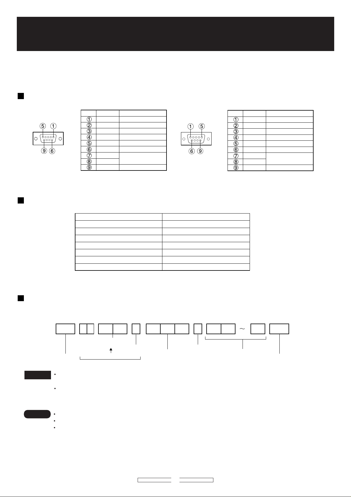
D-Sub 9-pin (female),
external appearance
Serial input terminal
Pin No.
Signal name
TXD
RXD
GND
CTS
RTS
Description
NC
Send data
Receive data
Connected internally
Ground
NC
Connected internally
NC
D-Sub 9-pin (male),
external appearance
Serial output terminal
Pin No.
Signal name
RXD
TXD
GND
RTS
CTS
Description
NC
Receive data
Send data
NC
Ground
NC
Connected internally
NC
Signal level
Synchronization method
Baud rate
Parity
Character length
Stop bit
X parameter
S parameter
RS-232C-compliant
Start-stop synchronization
9 600bps
None
8 bits
1 bit
None
None
PT-D10000/DW10000 PT-D7700/DW7000 PT-D5600/DW5000 PT-D5500 PT-D3500
The main unit is equipped with SERIAL terminals located in its terminal section on the side, and this terminal is
compliant with RS-232C.
Pin assignments and signal names
Communication conditions (Factory setting)
Basic format
Transmission from the computer begins with STX, then the ID, command, parameter, and ETX are sent in this
order. Add parameters according to the details of control.
STX C1 C2 C3 : P1 P2 Pn ETXA D I 1 I 2 ;
Two ID characters
Start
(2 bytes)
ZZ, 1 to 64 and 0A to 0Z
ID designate
Semicolon
3 command
characters (3 bytes)
Colon
Parameter
(undefined length)
End
Attention
Note
No command can be sent or received for 10 to 60 seconds after the lamp starts lighting. Try
sending any command after that period has elapsed.
When sending several commands, be sure to wait for more than 0.5 seconds after receiving a
response from the projector, and then send the next command.
When sending commands without parameters, a colon (:) is not necessary.
If a wrong command is received, the projector will send an ER401 or ER402 command to the computer.
Projector ID supported on the RS-232C interface is ZZ (ALL) and a group of 1 to 64 and 0A to 0Z.
If a command is sent with a projector ID specified, the projector will return answer back only in the
following cases:
If it coincides with the projector ID,
ID specification is ALL and VPS-SYSTEM is the master, or
ID specification is group and Group is the master.
1
Page 2

Control commands
Item Command:Parameter Function Call Back
POWER PON POWER ON PON YES YES YES YES
POF STANDBY(POWER OFF) POF YES YES YES YES
FREEZE OFZ:0 FREEZE OFF OFZ:0 NO YES YES YES
OFZ:1 FREEZE ON OFZ:1 NO YES YES YES
AUTO SETUP OAS AUTO SETUP OAS YES YES YES YES
SHUTTER OSH:0 SHUTTER OFF OSH:0 YES YES YES YES
OSH:1 SHUTTER ON OSH:1 YES YES YES YES
INPUT SELECT IIS:RG1 RGB-1 IIS:RG1 YES YES YES YES
IIS:RG2 RGB-2 IIS:RG2 YES YES YES YES
IIS:RG3 RGB-3 IIS:RG3 NO NO NO NO
IIS:VID VIDEO IIS:VID YES YES YES YES
IIS:SVD S-VIDEO IIS:SVD YES YES YES YES
IIS:DVI DVI IIS:DVI YES NO YES YES
IIS:AUX AUX IIS:AUX YES YES NO NO
IIS:AUX,AW1 AUX LINE(Only MD95VM2) IIS:AUX,AW1 NO YES NO NO
IIS:AUX,AW2 AUX Y/C (Only MD95VM2) IIS:AUX,AW2 NO YES NO NO
TEST OTS:00 EXIT Test Pattern OTS:00 YES YES YES YES
OTS:01 WHITE OTS:01 YES YES YES YES
OTS:02 BLACK OTS:02 YES YES YES YES
OTS:03 CHECKER1 OTS:03 YES YES YES YES
OTS:04 CHECKER2 OTS:04 YES YES NO NO
OTS:05 1% WHITE WINDOW OTS:05 YES YES YES YES
OTS:06 1% BLACK WINDOW OTS:06 YES YES YES YES
OTS:07 CROSS HATCH OTS:07 YES YES YES YES
OTS:08 COLOR BAR OTS:08 YES YES YES YES
OTS:09 RAMP OTS:09 NO NO YES YES
ON SCREEN OOS:0 OSD OFF OOS:0 YES YES YES YES
OOS:1 OSD ON OOS:1 YES YES YES YES
MUTE AMT:0 AUDIO MUTE OFF AMT:0 NO NO NO YES
AMT:1 AUDIO MUTE ON AMT:1 NO NO NO YES
D10000/DW10000
D7700/DW7000 D5600/DW5000 D3500 Remarks
D5500
Adjustment Mode
Item Command:Parameter Function Call Back
PICTURE MODE VPM:NAT NATURAL VPM:NAT YES YES YES YES
VPM:STD STANDARD VPM:STD YES YES YES YES
VPM:DYN DYNAMI VPM:DYN YES YES YES YES
VPM:CIN CINEMA VPM:CIN YES YES YES YES
VPM:GRA GRAPHIC VPM:GRA YES YES YES YES
VPM:USR USER VPM:USR YES NO NO NO
COLOR VCO:p1p2p3 COLOR Value Adjust VCO:p1p2p3 YES YES YES YES From0 To 100 *1
TINT VTN:p1p2p3 TINT Value Adjust VTN:p1p2p3 YES YES YES YES From0 To 62 *3
COLOR TEMP. OTE:0 LOW OTE:0 YES YES NO NO
OTE:1 MIDDLE OTE:1 YES YES YES YES
OTE:2 HIGH OTE:2 YES YES YES YES
OTE:3 DYNAMIC OTE:3 NO NO NO NO
OTE:4 USER (USER1) OTE:4 YES NO YES YES
OTE:5 STANDARD OTE:5 NO NO NO NO
OTE:6 NATURAL OTE:6 NO NO NO NO
OTE:7 CINEMA OTE:7 NO NO NO NO
OTE:8 GRAPHIC OTE:8 NO NO NO NO
OTE:9 USER2 OTE:9 YES YES NO NO
OTE:10 DEFAULT OTE:10 YES YES YES YES
CONTRAST VCN:p1p2p3 CONTARST Value Adjust VCN:p1p2p3 YES YES YES YES From0 To 63 *1
BRIGHTNESS VBR:p1p2p3 BRIGHTNESS Value Adjust VBR:p1p2p3 YES YES YES YES From0 To 63 *1
SHARPNESS VSR:p1p2p3 SHARPNESS Value Adjust VSR:p1p2p3 YES YES YES YES <SD> From0 To 15,
SET DATE TSD:y1y2y3y4m1m2d1d2w Set Date
SET TIME TST:h1h2m1m2s1s2 Set Time TST:h1h2m1m2s1s2 YES YES YES YES *2
VOLUME AVL:p1p2p3 AUDIO VOLUME AVL:p1p2p3 NO NO NO YES
*1: Regarding p1p2p3, +1,+01,+001,1,01,001 are All Accepted *2: Date/Time Should be set on UTC (Coordinate Universal Time) *3: Only use of PT-D10000 and PT-DW10000
TSD:y1y2y3y4m1m2d1d2w
D10000/DW10000
YES YES YES YES
NO NO NO YES
D7700/DW7000 D5600/DW5000 D3500 Remarks
D5500
<HD,RGB>From0 To 7 *1
y1y2y3y4m1m2d1d2+Date of Week
Mon=1,Tue=2,
...
,Sun=7 *2
2
Page 3

Status Asking Comman
Item Command:Parameter Function Call Back
POWER CONDITION
FREEZE QFZ Freeze Function Status 0 NO YES YES YES OFF
SHUTTER QSH Shutter Status 0 YES YES YES YES OFF
INPUT SIGNAL QIN Input Signal Status RG1 YES YES YES YES RGB1
TEST QTS Test Pattern Status 00 YES YES YES YES
02 YES YES YES YES BLACK
ON SCREEN QOS ON SCREEN Status 0 YES YES YES YES off
PICTURE MODE QPM PICTURE MODE Status NAT YES YES YES YES NATURAL
USR YES NO NO NO USER
COLOR QVC COLOR Adjust Value Check p1p2p3 YES YES YES YES
TINT QVT TINT Adjust Value Check p1p2p3 YES YES YES YES
COLOR TEMP. QTE COLOR TEMP Status Check 0 YES YES NO NO LOW
CONTRAST QVR
BRIGHTNESS QVB BRIGHTNES Adjust Value p1p2p3 YES YES YES YES
SHARPNESS QVS SHARPNESS Adjust Value p1p2p3 YES YES YES YES
SET RUNTIME QST Set Run Time CHeck p1p2p3p4p5 YES YES YES YES 00000h~99999h
LAMP ON TIME Q$L:1 LAMP1 Run Time Check p1p2p3p4 YES YES YES YES 0000h~9999h
LAMP SELECT QSL Lamp Operation Mode Check 0 YES YES NO DUAL
QPW Main Power Status 000 YES YES YES YES STANDBY(OFF)
001 YES YES YES YES ON
1 NO YES YES YES ON
1 YES YES YES YES ON
RG2 YES YES YES YES RGB2
RG3 NO NO NO NO RGB3
VID YES YES YES YES VIDEO
SVD YES YES YES YES S-VIDEO
DVI YES NO YES YES DVI
AUX YES YES NO NO AUX
QIN:AW AUX,AW1 NO YES NO NO AUX LINE
QIN:AW AUX,AW2 NO YES NO NO AUX Y/C
01 YES YES YES YES WHITE
03 YES YES YES YES CHECKER1
04 YES YES NO NO CHECKER2
05 YES YES YES YES
06 YES YES YES YES
07 NO YES YES YES CROSS HATCH
08 YES YES YES YES COLOR BAR
09 NO NO YES YES RAMP
1 YES YES YES YES on
STD YES YES YES YES STANDARD
DYN YES YES YES YES DYNAMIC
CIN YES YES YES YES CINEMA
GRA YES YES YES YES GRAPHIC
1 YES YES YES YES MIDDLE
2 YES YES YES YES HIGH
3 NO NO NO NO DYNAMIC
4 YES YES YES YES USER (USER1)
5 NO NO NO NO STANDARD
6 NO NO NO NO NATURAL
7 NO NO NO NO CINEMA
8 NO NO NO NO NATURAL
9 YES YES NO NO USER2
10 YES YES YES YES DEFAULT
CONTARST Adjust Value Checking
Q$L:2 LAMP2 Run Time Check p1p2p3p4 YES YES YES NO
Q$L:3 LAMP3 Run Time Check p1p2p3p4 YES NO NO NO
Q$L:4 LAMP4 Run Time Check p1p2p3p4 YES NO NO NO
p1p2p3 YES YES YES YES
1 YES YES NO SINGLE
2 YES YES NO LAMP1
3 YES YES NO LAMP2
D10000/DW10000
D7700/DW7000 D5600/DW5000 D3500 Meaning Remarks
D5500
EXIT Test Pattern
1% WHITE WINDOW
1% BLACK WINDOW
MD95VM2
MD95VM2
3
Page 4

LAMP SELECT QSL Lamp Operation Mode Check 0 YES NO NO NO QUAD (4 lamp)
(D10000/DW10000)
1 YES NO NO NO L1/L4
2 YES NO NO NO L2/L3
3 YES NO NO NO DUAL (2 lamp)
4 YES NO NO NO L1/L2/L3
5 YES NO NO NO L1/L2/L4
6 YES NO NO NO L1/L3/L4
7 YES NO NO NO L2/L3/L4
8 YES NO NO NO TRIPLE (3 lamp)
9 YES NO NO NO L1
10 YES NO NO NO L2
11 YES NO NO NO L3
12 YES NO NO NO L4
13 YES NO NO NO SINGLE
LAMP POWER QLP LAMP POWER Mode Check 0 NO YES YES YES HIGH
1 NO YES YES YES LOW
2 NO TBD YES YES (RESERVED)
VPS SYSTEM QVY VPS SYSTEM Check 0 YES YES YES NO SLAVE
1 YES YES YES NO MASTER
INPUT BOARD QIB
Check the type of Input Board
p1p2p3p
............
NO YES NO NO MD95VM2
(Voluntary length) YES YES NO NO MD95SD1
NO YES NO NO MD95SD2
YES YES NO NO MD95SD3
NO YES NO NO MD95RGB
NO YES NO NO MD75NT
YES YES NO NO MD75DV
YES YES NO NO MD77SD1
YES YES NO NO MD77SD3
YES YES NO NO MD77DV
YES YES NO NO NONE No board
Unknown board
Unsupported board
TEMP CHECK QTM:0
Check the status of Temperature
YES YES NO NO UNKNOWN
YES YES NO NO NOT SUPPORT
p1p2p3p4/p5p6p7p8 YES YES YES YES INPUT AIR
QTM:1 Sensor (Celsius/ Fahrenheit) YES YES NO NO OUTPUT AIR
QTM:2 YES YES YES YES
GET DATE QGD Check the Day
y1y2y3y4m1m2d1d2w
YES YES YES YES
OPTICAL MODULE
Yyyymmdd (day of the week)
Mon=1,Tur=2,
GET TIME QGT Check the Time h1h2m1m2s1s2 YES YES YES YES hhmmss UTC
MUTE QAM Audio Mute Status 0 NO NO NO YES MUTE OFF
1 NO NO NO YES MUTE ON
VOLUME QAV Volume Status p1p2p3 NO NO NO YES
...
,Sun=7
4
Page 5

Extended format for lens
Transmission from the computer begins with STX, then the ID, command, parameter, and
ETX are sent in this order.
STX
Start
0x02
*Lens commands are binary 8byte command. PT-D7600/D7500 ware supported version 2.07
ID: D ALL=0x00, ID1=0x01, ID2=0x02, ID3=0x03, ID4=0x04,... ,ID63=0x3f, ID64=0x40 Projector default setting is ID ALL.
ID: D ALL=0x00, ID1=0x01, ID2=0x02, ID3=0x03, ID4=0x04,... ,ID63=0x3f, ID64=0x40 Projector default setting is ID ALL.
C1 C2: 0xb1 0x7c
C1 C2: 0xb1 0x7c
P1 P2 P3 Function D10000/DW10000 D7700/DW7000 D5600/DW5000/D5500 D3500
0x00 0x00 0x00 HORIZONTAL SHIFT RIGHT SLOW YES YES NO NO
0x00 0x01 0x00 HORIZONTAL SHIFT RIGHT NORMAL YES YES NO NO
0x00 0x02 0x00 HORIZONTAL SHIFT RIGHT FAST YES YES NO NO
0x00 0x00 0x01 HORIZONTAL SHIFT LEFT SLOW YES YES NO NO
0x00 0x01 0x01 HORIZONTAL SHIFT LEFT NORMAL YES YES NO NO
0x00 0x02 0x01 HORIZONTAL SHIFT LEFT FAST YES YES NO NO
0x01 0x00 0x00 VERTICAL SHIFT UP SLOW YES YES YES YES
0x01 0x01 0x00 VERTICAL SHIFT UP NORMAL YES YES YES YES
0x01 0x02 0x00 VERTICAL SHIFT UP FAST YES YES YES YES
0x01 0x00 0x01 VERTICAL SHIFT DOWN SLOW YES YES YES YES
0x01 0x01 0x01 VERTICAL SHIFT DOWN NORMAL YES YES YES YES
0x01 0x02 0x01 VERTICAL SHIFT DOWN FAST YES YES YES YES
0x02 0x00 0x00 FOCUS +(SHORT) SLOW YES YES YES YES
0x02 0x01 0x00 FOCUS +(SHORT) NORMAL YES YES YES YES
0x02 0x02 0x00 FOCUS +(SHORT) FAST YES YES YES YES
0x02 0x00 0x01 FOCUS -(LONG) SLOW YES YES YES YES
0x02 0x01 0x01 FOCUS -(LONG) NORM YES YES YES YES
0x02 0x02 0x01 FOCUS -(LONG) FAS YES YES YES YES
0x03 0x00 0x00 ZOOM + SLOW YES YES YES YES
0x03 0x01 0x00 ZOOM + NORMAL YES YES YES YES
0x03 0x02 0x00 ZOOM + FAST YES YES YES YES
0x03 0x00 0x01 ZOOM - SLOW YES YES YES YES
0x03 0x01 0x01 ZOOM - NORMAL YES YES YES YES
0x03 0x02 0x01 ZOOM - FAST YES YES YES YES
0x00 0x80 0x01 HORIZONTAL SHIFT HOME POSITION START YES NO NO NO
0x00 0x80 0x00 HORIZONTAL SHIFT HOME POSITION STOP YES NO NO NO
For example
1. LENS ZOOM + NORMAL for ID ALL
Send 8 byte command 0x02 0x00 0xb1 0x7c 0x03 0x01 0x00 0x03
Receive 8 byte message from projector 0x02 0x00 0xb3 0x7c 0x03 0x01 0x00 0x03
ID
ID
0x00 to 0x40
C1
C2
command
0xb1, 0x7c
P1
P2 P3
Parameter
2. VERTICAL SHIFT DOWN FAST for ID ALL
Send 8 byte command 0x02 0x00 0xb1 0x7c 0x01 0x02 0x01 0x03
Receive 8 byte message from projector 0x02 0x00 0xb3 0x7c 0x01 0x02 0x01 0x03
ETX
End
0x03
5
Page 6

Cable specifications
<Connecting to a PC>
Attention
To connect the computer to the SERIAL terminal, prepare an adequate communication cable that
fits to your personal computer.
Projector
1
2
3
4
5
6
7
8
9
NC
NC
NC
NC
Computer
(DTE specifications)
NC
NC
NC
NC
1
2
3
4
5
6
7
8
9
Transmission from the computer
(Used Only for PT-D7700/DW7000, PT-D5600/DW5000 and PT-D3500)
Transmission from the computer begins with STX, then the ID, command, and ETX are sent in this order.
STX
Start
0x02
Self-diagnosis result read commands is binary 4 byte command.
ID:
Projector default setting is ID ALL.
ID ALL=0x00, ID1=0x01, ID2=0x02, ID3=0x03, ID4=0x04, ... ,ID63=0x3f, ID64=0x40
ID
ID
0x00 ~ 0x40
C1
Command
0xfe
ETX
End
0x03
Responses from the projector
STX
Start
0x02
Responses are binary 12 byte command.
Self-diagnosis results are 4 byte (32bit) command.
P5-P8, all 4 bytes are extended bits and the values are undefined.
ID
ID
0x00 ~ 0x40
C1
Command
0xfe
P1 P2 P3 P4 P5 P6 P7 P8 ETX
bit31
Self-diagnosis information 4 bytes
6
(32bits)
bit0
End
0x03
Page 7

Bit allocation for Self-diagnosis information
Bit Title Description
bit31 MAIN CPU BUS ERROR
bit30 FAN ERROR
bit29 OPTICS MODULE
TEMPERATURE ERROR
bit28 INPUT AIR TEMPERATURE
ERROR
bit27 OUTPUT AIR OR
LAMP AMBIENT
TEMPERATURE ERROR
bit26 EXTENSION - NO NO NO
bit25 LAMP2 REMAIN TIME
ERROR (Shutdown)
bit24 LAMP1 REMAIN TIME
ERROR (Shutdown)
bit23
bit22
bit21 APERTURE
bit20 SHUTTER ERROR Power on
bit19 OPTICS MODULE TEMP.
bit18 INPUT AIR TEMP.
bit17 OUTPUT AIR OR LAMP
bit16 CLOCK BATTELY
bit15 OPTICS MODULE SENSOR
bit14 OPTICS MODULE SENSOR
bit13 INPUT AIR HIGH TEMP.
bit12 OUTPUT AIR OR LAMP
bit11 TEST Main power on YES YES YES
bit10 AIR FILTER Main power on NO YES NO
bit09 EXTENSION - NO NO NO
bit08 EXTENSION - NO NO NO
bit07 LAMP2 REMAIN
bit06 LAMP1 REMAIN
bit05 EXTENSION - NO NO NO
bit04 EXTENSION - NO NO NO
bit03 AIRFLOW SENSOR Main power on NO YES NO
bit02 COLOR WHEEL
bit01 EXTENSION - NO NO NO
bit00 EXTENSION - NO
LAMP2 FAILED TO LIGHT
LAMP1 FAILED TO LIGHT
(CONTRAST- SHUTTER)
ERROR
SENSOR ERROR
SENSOR ERROR
AMBIENT TEMPERATURE
ERROR
WARNING
LOW TEMP. WARNING
HIGH TEMP. WARNING
WARNING
AMBIENT HIGH TEMP.
WARNING
TIME WARNING
TIME WARNING
ERROR
Trouble has occurred in the microcomputer circuitry.
If it does not recover after turning power back on, consult your dealer.
Trouble has occurred in the fan or its drive circuit.
If it does not recover after turning power back on, consult your dealer.
The temperature inside the projector is high and the projector has shut down.
• Check if the ventilation port is blocked.
• Is the room air temperature too high?
• Check the air filter for clogging.
Undefined value
The lamp runtime has exceeded the prescribed cumulative time,
and it is now time to replace the lamp.
The lamp has failed to light.
Did you turn the power back on immediately after turning it off?
Trouble has occurred in the aperture.
If it does not recover after turning power back on, consult your dealer.
Trouble has occurred in the shutter circuitry.
If it does not recover after turning power back on, consult your dealer.
Trouble has occurred in the temperature detection sensor inside the projector.
Consult your dealer.
Trouble has occurred in the sensor used to detect the input air temperature.
Consult your dealer.
Trouble has occurred in the sensor used to detect the output air temperature
or lamp ambient temperature. Consult your dealer.
The battery has been run out. consult your dealer.
It may be that the projector is being used where the ambient temperature is
low (approx. 0). If the temperature in the projector does not go up within
5 min., the projector will shut down.
The temperature inside the projector is high. If the temperature goes up,
the projector will shut down.
• Check if the ventilation port is blocked.
• Is the room air temperature too high?
• Check the air filter for clogging.
Undefined value
Undefined value
Too much dust accumulates on the air filter.
Turn off the MAIN POWER switch and clean the air filter.
Undefined value
Undefined value
It is time to replace the lamp. Prepare the new lamp.
The projector will shut down within 200 hours.
Undefined value
Undefined value
Trouble has occurred in the air volume sensor. Consult your dealer.
Trouble has occurred in the color wheel or its drive circuit.
If it does not recover after turning power back on, consult your dealer.
Undefined value
Undefined value
Condition to clear bit
Power on YES YES YES
Power on YES YES YES
Power on YES YES YES
Power on YES YES YES
Power on YES YES YES
LAMP 2 reset YES YES NO
LAMP 1 reset YES YES YES
LAMP 2 illuminates
LAMP 1 illuminates
Power on or
normal operation of
the aperture
Main power on YES YES YES
Main power on YES YES YES
Main power on YES NO YES
The battery has
been changed.
• Higher
temperature than the
warning level during
power on
• Power on
• Higher
temperature than the
warning level during
power on
• Power on
LAMP 2 reset YES YES NO
LAMP 1 reset YES YES YES
Power on NO YES YES
D7700/DW7000 D5600/DW5000 D5500 D3500
YES
YES
YES
YES
YES
NO
YES
YES
YES YES NO
YES YES
YES NO NO
YES or
normal operation
of the shutter
NO YES YES
YES YES YES
YES YES YES
YES YES YES
YES YES YES
NO YES
NO NO
YES
YES YES
NO
NO
YES
YES
NO
YES
YES
YES
YES
YES
YES
NO
NO
NO
YES
YES
NO
NO
NO
YES
NO
NO
*The value of NO is undefined.
7
Page 8

Example
-When the transmission ID from PC is ID ALL and the projector ID is ALL,
Send (the data sent from the computer)
0x02 0x00 0xfe 0x03
Receive (the data received by the computer)
0x02 0x00 0xfe 0x10 0x00 0x00 0x00 0x00 0x00 0x00 0x00 0x03
Self-diagnosis information is x10000000, or bit 28 is one so that it is Input temp. error.
- When the transmission ID from PC is ID ALL and the projector ID is 2
Send (the data sent from the computer)
0x02 0x00 0xfe 0x03
Receive (the data received by the computer)
0x02 0x02 0xfe 0x00 0x00 0x00 0x00 0x00 0x00 0x00 0x00 0x03
Self-diagnosis information is 0x00000000 and it is normal.
Note
Values of extension bits are undefined. It is normal even if self-diagnosis information is 0x00000001.
8
Page 9

Transmission from the computer
(Used Only for PT-D10000/DW10000)
Transmission from the computer begins with STX, then the ID, command, and ETX are sent in this order.
STX
Start
0x02
ID
ID
0x00 ~ 0x40
C1
Command
0xfe
C2
Command
0xfe
ETX
End
0x03
When self-diagnosis result operation in the PT-D10000/DW10000, read commands of C1 and C2 command is necessary.
A command is binary 4 byte command.
ID:
Projector default setting is ID ALL.
ID ALL=0x00, ID1=0x01, ID2=0x02, ID3=0x03, ID4=0x04, ... ,ID63=0x3f, ID64=0x40
Responses from the projector
(Used Only for PT-D10000/DW10000)
STX
Start
0x02
ID
ID
0x00 ~ 0x40
C1
Command
0xfe
Command
0xfe
bit127
P1 P2 P3 P14 P15 P16C2
bit0
Self-diagnosis information 16 bytes
(128 bits)
ETX
End
0x03
Responses are binary 21 byte command.
Self-diagnosis results are 16 byte (128bit) command.
9
Page 10

Parameters (*2 to *17)
Bit Title Description Condition to clear bit
127 —
126 —
125 —
124 —
123 —
122 —
121 FM COMMUNICATION ERROR Error in communication with FM. Main power on
120 FPGA2 SETTING ERROR
119 FPGA1 SETTING ERROR
118 FM-B TEST FAIL Power on
117 FM-G TEST FAIL
116 FM-R TEST FAIL
115 BOARD A NOT INITIALIZED Board A initialized
114 IIC COMMUNICATION RETRY 17
113 IIC COMMUNICATION RETRY 16
112 IIC COMMUNICATION RETRY 15
111 IIC COMMUNICATION RETRY 14
110 IIC COMMUNICATION RETRY 13
109 IIC COMMUNICATION RETRY 12
108 IIC COMMUNICATION RETRY 11
107 IIC COMMUNICATION RETRY 10
106 IIC COMMUNICATION RETRY 9
105 IIC COMMUNICATION RETRY 8
104 IIC COMMUNICATION RETRY 7
103 IIC COMMUNICATION RETRY 6
102 IIC COMMUNICATION RETRY 5
101 IIC COMMUNICATION RETRY 4
100 IIC COMMUNICATION RETRY 3
99 IIC COMMUNICATION RETRY 2
98 IIC COMMUNICATION RETRY 1
97 NETWORK MICROCOMPUTER COMMUNICATION ERROR Main power on
96 RESIZE SETTING ERROR Main power on
86 LENS SHIFT ERROR
85 FPGA EXPANSION ERROR Main power on
84 RAM ERROR
83 FLASH ROM ERROR
82 FPGA2 FULL-HD CONFIG. ERROR Power on
81 FPGA2 SXGA+ CONFIG. ERROR
80 FPGA1 CONFIG. ERROR
79 LAMP 4 PFC ERROR Power on
78 LAMP 3 PFC ERROR
77 LAMP 2 PFC ERROR
76 LAMP 1 PFC ERROR
75 LAMP 4 NOT INITIALIZED The lamps EEPROM was not initialized. Lamp EEPROM initialized
74 LAMP 3 NOT INITIALIZED
73 LAMP 2 NOT INITIALIZED
72 LAMP 1 NOT INITIALIZED
71 DC 5.0 V ERROR
70 DC 3.3 V ERROR
69 DC 2.5 V ERROR
68 CLEANER MECHANISM ERRO The cleaning process timed out Cleaning performed
67 APERTURE ERROR
66 SHUTTER ERROR A shutter error has occurred. Shutter on/off
65 FAN ERROR 18 BALLAST2 FAN Normal fan operation
64 FAN ERROR 17 BALLAST2 FAN
63 FAN ERROR 16 L-PROSM FAN
62 FAN ERROR 15 R-PROSM FAN
61 FAN ERROR 14 B-LIQUID COOLING
60 FAN ERROR 13 G-LIQUID COOLING
59 FAN ERROR 12 R-DMD FAN
58 FAN ERROR 11 EXAUST FAN R
57 FAN ERROR 10 EXAUST FAN L
56 FAN ERROR 9 EXAUST FAN C
55 FAN ERROR 8 RADIATOR FAN
54 FAN ERROR 7 BALLAST3 FAN
53 FAN ERROR 6 BALLAST1 FAN
10
Page 11

52 FAN ERROR 5 LAMP4 FAN Normal fan operation
51 FAN ERROR 4 LAMP3 FAN
50 FAN ERROR 3 LAMP2 FAN
49 FAN ERROR 2 LAMP1 FAN
48 FAN ERROR 1 P-UNIT FAN
47 —
46 —
45 —
44 —
43 —
42 —
41 —
40 —
39 —
38 —
37 CHANGE INTERNAL CLOCK BATTERY Date/time is invalid (before Jan. 1, 2006 or Jan. 1, 2036 or later). Date/time reset (after battery change)
36 FILTER CLOGGED ERROR
35 AIR VOLUME SENSOR NOT FOUND The air volume sensor is not found. Main power on
34 OUTPUT AIR SENSOR NOT FOUND The output air sensor is not found.
33 DMD SENSOR NOT FOUND The DMD sensor is not found.
32 INPUT AIR SENSOR NOT FOUND The input air sensor is not found.
29 LAMP COVER NOT CLOSED The lamp cover is not closed (for more than 1 second continuously). Lamp cover closed, then main power on
28 AC VOLTAGE DROP WARNING (BELOW 90 V)
27 LAMP 4 NOT MOUNTED The lamp is not mounted. Lamp mounted, then main power on
26 LAMP 3 NOT MOUNTED
25 LAMP 2 NOT MOUNTED
24 LAMP 1 NOT MOUNTED
23 LAMP 4 IGNITIONFAILURE The lamp fails to ignite. Lamp illumination processing performed
22 LAMP 3 IGNITIONFAILURE
21 LAMP 2 IGNITIONFAILURE
20 LAMP 1 IGNITIONFAILURE
19 LAMP 4 ILLUMINATION FAILURE The lamp fails to illuminate.
18 LAMP 3 ILLUMINATION FAILURE
17 LAMP 2 ILLUMINATION FAILURE
16 LAMP 1 ILLUMINATION FAILURE
15 LAMP 4 USAGE TIME ELAPSED The lamp usage time exceeds the stipulated value Lamp replaced
14 LAMP 3 USAGE TIME ELAPSED
13 LAMP 2 USAGE TIME ELAPSED
12 LAMP 1 USAGE TIME ELAPSED
11 LAMP 4 USAGE TIME WARNING The lamp usage time exceeds the stipulated value.
10 LAMP 3 USAGE TIME WARNING
9 LAMP 2 USAGE TIME WARNING
8 LAMP 1 USAGE TIME WARNING
7 DMD LOW TEMP. ERROR The DMD ambient temperature is lower than the stipulated value.
6 OUTPUT AIR TEMP. ERROR The output air temperature exceeds the stipulated value. Output air temperature below stipulated value
5 DMD TEMP. ERROR The DMD ambient temperature exceeds the stipulated value. DMD ambient temperature below stipulated value
4 INPUT AIR ERROR The input air temperature exceeds the stipulated value. Input air temperature below stipulated value
3 DMD LOW TEMP. WARNING The DMD ambient temperature is lower than the stipulated value.
2 OUTPUT AIR TEMP. WARNING The output air temperature exceeds the stipulated value. Output air temperature below stipulated value
1 DMD TEMP. WARNING The DMD ambient temperature exceeds the stipulated value. DMD ambient temperature below stipulated value
0 INPUT AIR TEMP. WARNING The input air temperature exceeds the stipulated value. Input air temperature below stipulated value
Note
* Make sure to specify option FEh for this unit.
DMD ambient temperature at or above stipulated value
DMD ambient temperature at or above stipulated value
11
Page 12

Example
-When the transmission ID from PC is ID ALL and the projector ID is ALL,
Send (the data sent from the computer)
0x02 0x00 0xfe 0xfe 0x03
Receive (the data received by the computer)
0x02 0x00 0xfe 0xfe 0x02 0x00 0x00 0x00 0x00 0x00 0x00 0x00 0x00 0x00 0x00 0x00 0x00 0x00
0x00 0x00 0x03
Self-diagnosis information is 0x0200000000000000, or bit 121 is one so that it is FM communication error.
- When the transmission ID from PC is ID ALL and the projector ID is 2
Send (the data sent from the computer)
0x02 0x00 0xfe 0xfe 0x03
Receive (the data received by the computer)
0x02 0x02 0xfe 0xfe 0x00 0x00 0x00 0x00 0x00 0x00 0x00 0x00 0x00 0x00 0x00 0x00 0x00 0x00
0x00 0x00 0x03
Self-diagnosis information is 0x0000000000000000 and it is normal.
12
 Loading...