

Panasonic PT-61LCX70 User Manual
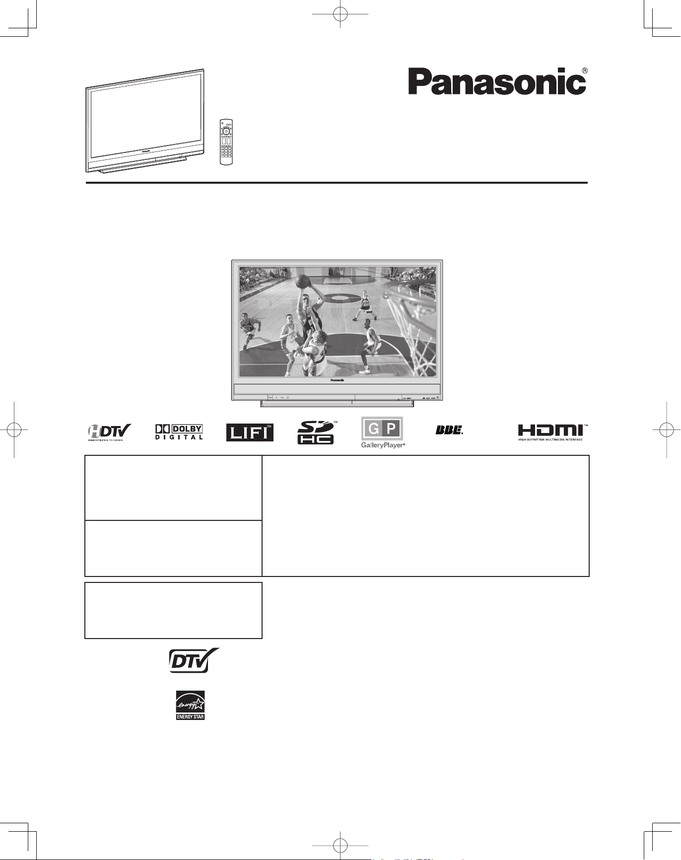
LIFI™ HDTV
Operating Instructions
Models No.
PT-56LCX70 / PT-61LCX70 /
PT-50LCX7 / PT-56LCX7 / PT-61LCX7 /
PT-50LCX7K / PT-56LCX70-K / PT-61LCX70-K
(USA)
For assistance, please call :
1-888-VIEW PTV(843-9788)
or, contact us via the web at:
http://www.panasonic.com/contactinfo
(Puerto Rico)
For assistance, please call :
787-750-4300
or visit us at www.panasonic.com
A
ViV
HD3D Sound
Three Important Reasons to Register Your Product Immediately!
1 Protect Your New Investment...
Register your new Projection Display for insurance purposes
in case your new Projection Display is stolen.
2 Product safety notification...
Registering your product can help us to contact you in the unlikely event
a safety notification is required under the Consumer Product Safety Act.
3 Improved Product Development...
Help us continue to design products that meet your needs.
Register online at www.panasonic.com/register
(Canada)
For assistance, please call :
1-800-561-5505
or visit us at www.panasonic.ca
* The presence of the DTV certification mark indicates that this product will
successfully receive digital television transmissions that conform to any and all of the
ATSC CERTIFIED *
DIGITAL TELEVISION
This operating instruction book is designed for use with models PT-56LCX70, PT-61LCX70, PT-50LCX7,
PT-56LCX7, PT-61LCX7, PT-50LCX7K, PT-56LCX70-K and PT-61LCX70-K. Illustrations in this manual show the
PT-56LCX70.
Before connecting, operating or adjusting this product, please read the instructions completely.
Please keep this manual for future reference.
video formats described in the ATSC Digital Television Standard.
As an ENERGY STAR® Partner, Panasonic Corporation of North America has
determined that this product or product model meets the
for energy efficiency.
ENERGY STAR
®
guidelines
LSQT1204 B
IMPORTANT SAFETY INSTRUCTIONS
CAUTION
RISK OF ELECTRIC SHOCK
DO NOT OPEN
WARNING: To reduce the risk of electric shock, do not remove cover or back. No
user-serviceable parts inside. Refer servicing to qualified service personnel.
This symbol warns the
user that uninsulated
voltage within the unit may
have sufficient magnitude
to cause electric shock.
Therefore, it is dangerous
to make any kind of
contact with any inside part
of this unit.
This symbol alerts the user
that important literature
concerning the operation
and maintenance of this
unit has been included.
Therefore, it should be read
carefully in order to avoid
any problems.
The pictorial
representation of a hot
surface within a triangle
is intended to tell the
user that parts inside the
product are a risk of burns
to persons.
Note to CATV System Installer:
This reminder is provided to call the CATV system installer’s attention to Article 820-40 of the NEC that provides
guidelines for proper grounding and, in particular, specifies that the cable ground shall be connected to the grounding
system of the building, as close to the point of cable entry as practical.
WARNING
To reduce the risk of electric shock, fire, injury to persons or damage to this product:
1) Read these instructions before using, connecting or adjusting this product.
2) Keep these instructions for future reference.
3) Heed all warnings on the product and in this Operating Instructions manual.
4) Follow all instructions carefully.
5) Do not use this apparatus near water. For example, near a bathtub, washbowl, kitchen sink, or laundry tub, in a
wet basement or near a swimming pool, and the like. Do not place objects filled with water, such as a vase or the
like, on top of this unit.
6) Clean only with a dry cloth. Do not use liquid cleaners or aerosol cleaners.
7) Do not block any ventilation openings. Install in accordance with the manufacturer’s instructions. Openings
in the cabinet are provided for ventilation to ensure reliable operation and to protect it from overheating. Never block
openings by placing the product on a bed, sofa or similar surfaces.
8) Do not install near any heat source such as radiators, heat registers, stoves, or other apparatus (including
amplifiers) that produces heat. Do not install in a built-in installation such as a bookcase or rack, unless proper
ventilation is provided or the manufacturer’s instructions have been adhered to.
9) Do not defeat the safety purpose of the polarized or grounding-type plug. A polarized plug has two blades
with one wider than the other. A grounding type plug has two blades and a third grounding prong. The
wide blade or the third prong are provided for your safety. If the provided plug does not fit into your outlet,
consult an electrician for replacement of the obsolete outlet.
10) Protect the power cord from being walked on or pinched particularly at plugs, convenience receptacles, and
the point where they exit from the apparatus.
11) Only use attachments/accessories specified by the manufacturer.
12) Use only with the cart, stand, tripod, bracket, or table specified by the manufacturer, or
sold with the apparatus. When a cart is used, use caution when moving the cart/apparatus
combination to avoid injury from tip-over.
13) Unplug this apparatus during lightning storms or when unused for long periods of time.
14) Refer all servicing to qualified service personnel. Servicing is required when the apparatus has been
damaged in any way, such as power-supply cord or plug is damaged, liquid has been spilled or objects
have fallen into the apparatus, the apparatus has been exposed to rain or moisture, does not operate
normally, or has been dropped.
2
IMPORTANT SAFETY INSTRUCTIONS (CONTINUED)
WARNING
AS WITH ANY SMALL OBJECT, SD CARDS CAN BE SWALLOWED BY YOUNG CHILDREN. DO NOT ALLOW
CHILDREN TO HANDLE THE SD CARD.
WARNING
TO REDUCE THE RISK OF FIRE OR ELECTRIC SHOCK, DO NOT EXPOSE THIS EQUIPMENT TO RAIN OR
MOISTURE. DO NOT PLACE OBJECTS FILLED WITH WATER, SUCH AS A VASE OR THE LIKE, ON TOP OF THIS
APPARATUS.
CAUTION
(1) This Projection Display is intended to be used with the following TV stand:
model TY-50LC7, TY-56LC7, TY-61LC7, TY-50LC70, TY-56LC70, or TY-61LC70 for the PT-56LCX70,
PT-61LCX70, PT-50LCX7, PT-56LCX7, PT-61LCX7, PT-50LCX7K, PT-56LCX70-K, or PT-61LCX70-K. Use with
other stands may result in the Projection Display becoming unstable, possibly causing injury.
(2) This Projection Display should not be exposed to direct sunlight, extreme temperatures or moisture, as this
can result in serious irreparable damage.
– For U.S.A. only –
(3) This Projection Display TV has an Electrodeless Discharge Lamp that contains mercury.
Disposal may be regulated in your community due to environmental considerations.
For disposal or recycling information, please contact your local authorities, or the Electronic Industries
Alliance: <http://www.eiae.org>
Trademarks
VGA and XGA are trademarks of International Business Machines Corporation.
•
Macintosh is a registered trademark of Apple Inc., USA.
•
SVGA is a trademark of the Video Electronics Standard Association.
•
Even if no special notation has been made of company or product trademarks, these trademarks have been fully respected.
Equipped with
•
and audio fidelity.
LIFI™ is a trademark of LUXIM
•
-TV Noise Reduction for true MTS reproduction. -TV Noise Reduction is required for good stereo separation
is a registered trademark, and is licensed by Technology Licensing.
®
Corporation.
HDMI, the HDMI logo and
High-Definition Multimedia
Interface are trademarks or
registered trademarks of HDMI
Licensing LLC.
ViV
HD3D Sound
A
Manufactured under license from BBE Sound, Inc.
Licensed by BBE Sound, Inc. under one or more of
the following US patents: 5510752, 5736897. BBE
and BBE symbol are registered trademarks of BBE
Sound, Inc.
Getting Start ed
Manufactured under license from Dolby
SDHC Logo is a trademark.
LIFI™ is a trademark of
LUXIM® Corporation.
EZ Sync™ is a trademark of
Matsushita Electric Industrial
Co., Ltd.
Laboratories. Dolby and the double-D symbol are
trademarks of Dolby Laboratories.
GalleryPlayer and the GalleryPlayer Logo are
trademarks of GalleryPlayer, Inc.
HDAVI Control™ is a trademark of
Matsushita Electric Industrial Co., Ltd.
Licensed by Fergason under UPS5717422.
License description: To view the license information for software used in this product, press MENU button and select
“Setup”→“About”→“License”. (p. 55)
Note
Do not allow a still picture to be displayed for an extended period, as this can cause a permanent afterimage to remain on this unit.
•
Examples of still pictures include logos, video games, computer images, teletext and images displayed in 4:3 mode.
3
Dear Panasonic Customer
Welcome to the Panasonic family of customers. We hope that you will have many years of enjoyment from your new
Projection Display.
To obtain maximum benefit from your set, please read these Instructions before making any adjustments, and retain
them for future reference.
Retain your purchase receipt also, and record the serial number of your set in the space provided on the rear cover of
these instructions.
Visit our Panasonic Web Site for USA : www.panasonic.com / for Canada : www.panasonic.ca
(USA)
(Puerto Rico)
(Canada)
– For U.S.A. –
For assistance, please call : 1-888-VIEW PTV(843-9788)
or, contact us via the web at: http://www.panasonic.com/contactinfo
For assistance, please call : 787-750-4300
or visit us at www.panasonic.com
For assistance, please call : 1-800-561-5505
or visit us at www.panasonic.ca
FCC STATEMENT:
NOTE:
This equipment has been tested and found to comply with the limits for a Class B digital device, pursuant to Part 15 of
the FCC Rules. These limits are designed to provide reasonable protection against harmful interference in a residential
installation. This equipment generates, uses and can radiate radio frequency energy and, if not installed and used
in accordance with the instructions, may cause harmful interference to radio communications. However, there is no
guarantee that interference will not occur in a particular installation. If this equipment does cause harmful interference to
radio or television reception, which can be determined by turning the equipment off and on, the user is encouraged to try
to correct the interference by one or more of the following measures:
Reorient or relocate the receiving antenna.
•
Increase the separation between the equipment and receiver.
•
Connect the equipment into an outlet on a circuit different from that to which the receiver is connected.
•
Consult the dealer or an experienced radio / TV technician for help.
•
FCC Caution:
To assure continued compliance, follow the attached installation instructions and use only shielded interface cables
when connecting to computer or peripheral devices. Any changes or modifications not expressly approved by the party
responsible for compliance could void the user’s authority to operate this equipment.
4
ANY CHANGES OR MODIFICATIONS TO THIS PTV RECEIVER NOT EXPRESSLY APPROVED BY PANASONIC
CORPORATION OF NORTH AMERICA COULD CAUSE HARMFUL INTERFERENCE, WHICH WOULD VOID THE
USER’S AUTHORITY TO OPERATE THIS EQUIPMENT.
The ClassⅡ insulation symbol (square within a square) indicates that this product has been evaluated and
tested to comply with ClassⅡ insulation requirements.
Declaration of Conformity
Models Number: PT-56LCX70/PT-61LCX70/PT-50LCX7/PT-56LCX7/PT-61LCX7
Trade Name: Panasonic
Responsible party: Panasonic Corporation of North America
Address: One Panasonic Way, Secaucus, New Jersey 07094
Telephone number: 1-888-VIEW PTV(843-9788)
This device complies with Part 15 of the FCC Rules. Operation is subject to the following two conditions: (1) This
device may not cause harmful interference, and (2) this device must accept any interference received, including
interference that may cause undesired operation.
CANADIAN NOTICE:
1. Cable Compatible Television Apparatus
2. This Class B digital apparatus complies with Canadian ICES-003.
Table of Contents
To
Start !
Use
Now !
IMPORTANT SAFETY INSTRUCTIONS ..................................... 2
Before Using ..................................................................................... 6
Location of Controls ........................................................................9
Installation ....................................................................................... 12
Recommended AV Connections ................................................... 21
Getting Start ed
Power ON / OFF .............................................................................. 24
Tuning channels ............................................................................. 26
Projection Display Operation ........................................................ 29
ASPECT Controls ........................................................................... 33
Basic OperationInformation Advanced Op er a tion
Enjoy
More !
Other
Information !
EZ Sync™ Feature .......................................................................... 34
Picture Adjustments....................................................................... 35
Audio Adjustments ......................................................................... 38
Sleep Timer Feature ....................................................................... 40
Lock Feature ................................................................................... 41
Viewing from SD Card .................................................................... 46
Setup Features................................................................................ 49
Warning Indicators ......................................................................... 56
Troubleshooting ............................................................................. 57
Specifications ................................................................................. 59
Customer Services Directory (for U.S.A.) .................................... 60
Limited Warranty (for U.S.A.) ........................................................61
Limited Warranty (for Canada) ...................................................... 62
Index ................................................................................................ 63
5
Before Using
Receiver Location
This Projection Display is intended to be used with an
optional stand or entertainment center. Consult your
dealer for available options.
Situate for comfortable viewing. Avoid placing where
sunlight or other bright light (including reflections) will fall
on the screen.
Use of some types of fluorescent lighting can reduce
Remote Control transmitter range.
Adequate ventilation is essential to prevent internal
component failure. Keep away from areas of excessive
heat or moisture.
Optional External Equipment
The Video / Audio connection between components can
be made with shielded video and audio cables. For best
performance, video cables should utilize 75 Ω coaxial
shielded cables. Cables are available from your dealer or
electronics store.
Before you purchase any cables, be sure you know
what type of output and input connectors your various
com po nents require. Also determine the length of cable
you’ll need.
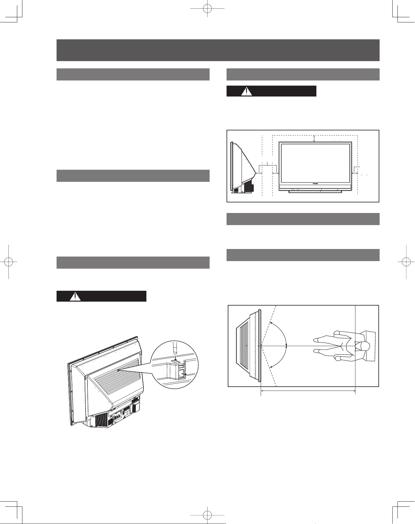
Safety Precaution
Please take safety precautions to prevent the unit from
falling over.
WARNING
The unit may tip or fall if not situated on a stable
surface, if pushed or during an earthquake. Use a
strong rope or chain (not included) to fasten the
Projection Display firmly to a strong wall support.
Installation Dimensions Diagram
CAUTION
Keep the unit at least 100 mm ( 4˝ ) away from the
wall to provide proper ventilation because warm air
is discharged. Blocking the ventilation opening of
the cooling fan may damage the unit.
100 mm (4˝)
100 mm (4˝)
100 mm (4˝)
100 mm (4˝)
100 mm
100 mm
(4˝)
(4˝)
Accessories
1. Remote Control (N2QAYB000103)
2. Batteries 2 “AA”
Viewing position
To optimize your viewing comfort, please follow the
viewing guidelines shown in the diagrams below.
If viewing for an extended period of time, sit as far back
from the screen as possible.
< Top view >
< Top view >
70º
70º
6
70º
70º
At least
At least
1.8 m (PT-50LCX7/PT-50LCX7K) /
1.8 m (PT-50LCX7/PT-50LCX7K) /
2.0 m (PT-56LCX70/PT-56LCX7/PT-56LCX70-K) /
2.0 m (PT-56LCX70/PT-56LCX7/PT-56LCX70-K) /
2.2 m (PT-61LCX70/PT-61LCX7/PT-61LCX70-K).
2.2 m (PT-61LCX70/PT-61LCX7/PT-61LCX70-K).
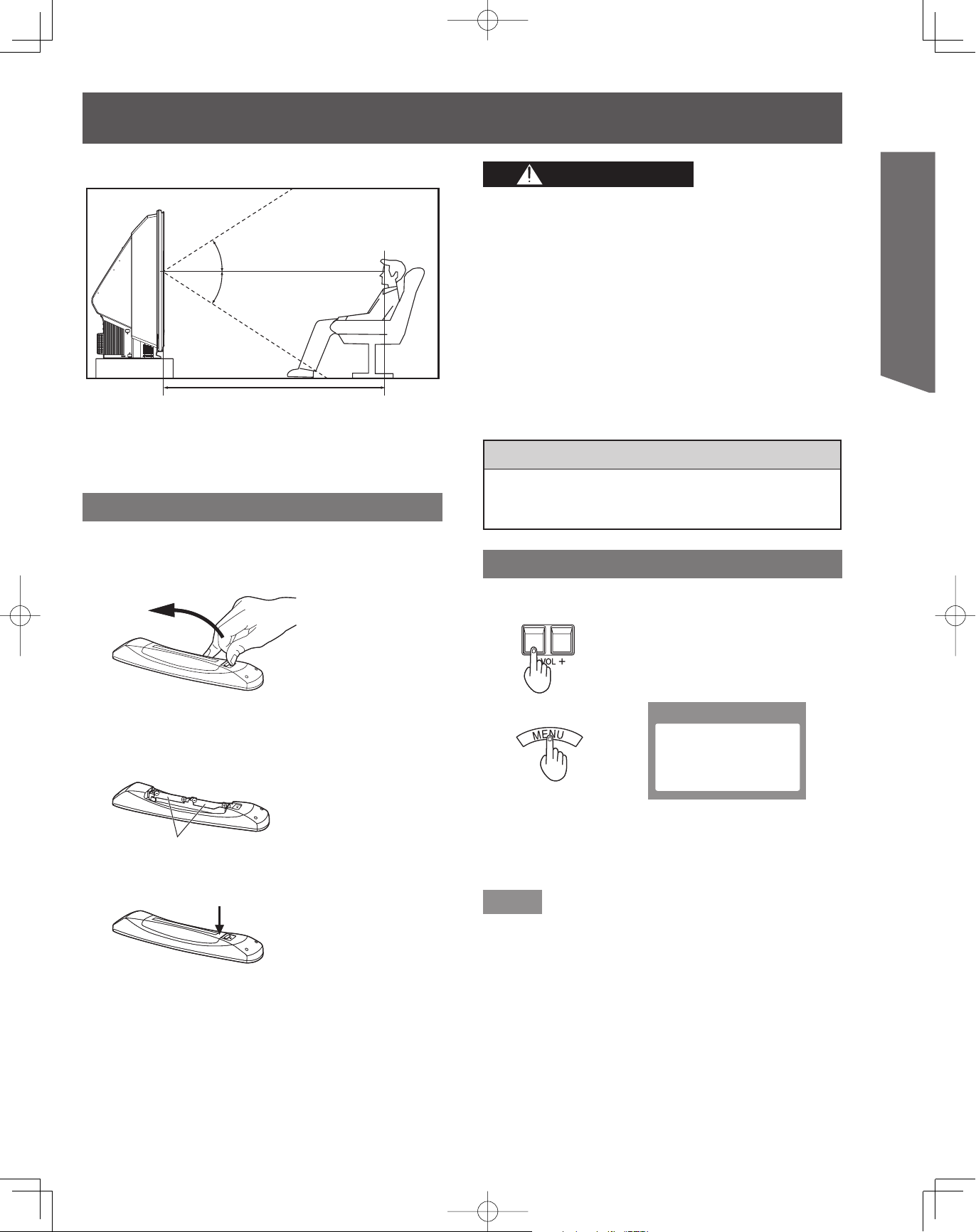
< Side view >
< Side view >
30º
30º
30º
30º
At least
At least
1.8 m (PT-50LCX7/PT-50LCX7K) /
1.8 m (PT-50LCX7/PT-50LCX7K) /
2.0 m (PT-56LCX70/PT-56LCX7/PT-56LCX70-K) /
2.0 m (PT-56LCX70/PT-56LCX7/PT-56LCX70-K) /
2.2 m (PT-61LCX70/PT-61LCX7/PT-61LCX70-K).
2.2 m (PT-61LCX70/PT-61LCX7/PT-61LCX70-K).
Remote Control Battery Installation
Requires two AA batteries (supplied).
CAUTION CAUTION
Incorrect battery installation can cause the batteries to
leak, leading to personal injury and/or damage to the
Remote Control.
Observe the following precautions:
1. Always replace batteries with a pair of new ones.
2. Do not combine a new battery with an old one.
3. Do not mix battery types (example: “Zinc Carbon”
with “Alkaline”).
4. Do not attempt to charge, short-circuit, disassemble,
heat or burn used batteries.
5. Battery replacement is necessary when the Remote
Control acts sporadically or stops operating the
Projection Display set.
Helpful Hints:
Helpful Hints:
Frequent Remote Control users choose long-lasting
•
Frequent Remote Control users choose long-lasting
•
Alkaline batteries as replacements.
Alkaline batteries as replacements.
Getting Start ed
1. While pressing in on the catch, open cover in
direction of arrow.
2. Install batteries in the battery compartment.
Battery polarity (+) and (-) must match the markings
•
inside the compartment.
Two AA sizeTwo AA size
3. Press cover until it snaps shut.
Reset All Memory Functions
Use when moving unit to a new location, or when First
Time Setup needs to be done over.
Press together the VOL- button
Press together the VOL- button
on the unit and MENU button on
on the unit and MENU button on
the Remote Control for more than
the Remote Control for more than
3 seconds.
3 seconds.
Selfcheck
Selfcheck
Selfcheck
Selfcheck
Selfcheck in progress.
Selfcheck in progress.
Selfcheck in progress.
Selfcheck in progress.
Please refrain from any
Please refrain from any
Please refrain from any
Please refrain from any
activity. Do not turn off
activity. Do not turn off
activity. Do not turn off
activity. Do not turn off
or unplug the TV.
or unplug the TV.
or unplug the TV.
or unplug the TV.
After the above message indication
After the above message indication
disappeared, unplug the unit then
disappeared, unplug the unit then
plug it back in and turn power ON.
plug it back in and turn power ON.
Note
When using “EZ Sync™ “HDAVI Control™””, with the device
•
connected, set “EZ Sync” first to “Off” and then “On” using the
Setup Menu. (p. 52-53)
7
Before Using (continued)
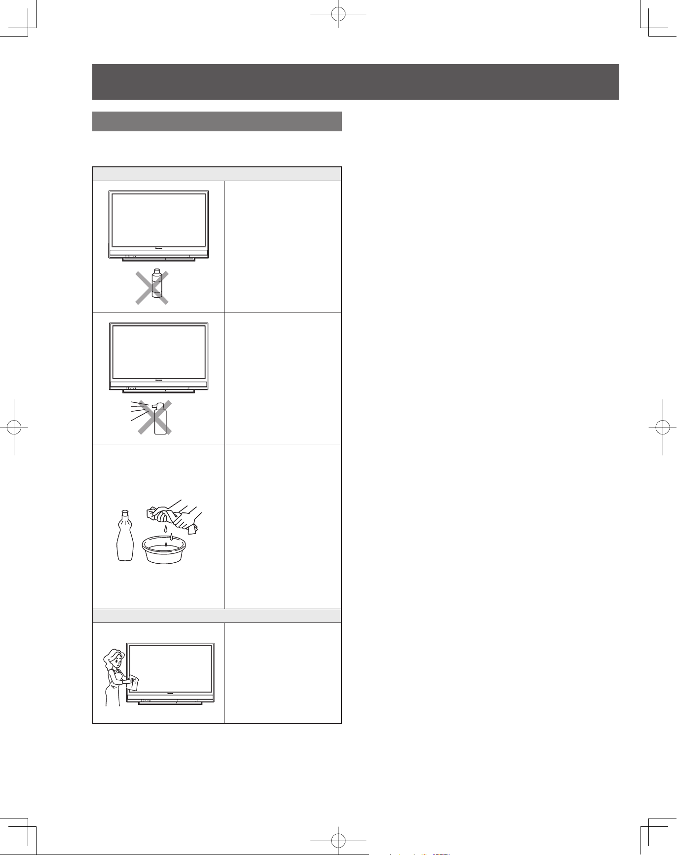
Cleaning
To ensure continued excellent performance from this
product, periodic cleaning is recommended.
Projection Display
Projection Display
The unit contains many
The unit contains many
plastic parts. For this reason
plastic parts. For this reason
DO NOT use benzine,
DO NOT use benzine,
thinner or other chemicals
thinner or other chemicals
to clean the unit.
to clean the unit.
DO NOT bring into contact
DO NOT bring into contact
with insecticide or other
with insecticide or other
volatile substances. DO
volatile substances. DO
NOT allow the unit to come
NOT allow the unit to come
into contact for extended
into contact for extended
periods with rubber or vinyl
periods with rubber or vinyl
products.
products.
Remove dirt and soiling by
Remove dirt and soiling by
wiping with a light cloth.
wiping with a light cloth.
Even if the unit is heavily
Even if the unit is heavily
soiled, do not apply cleaner
soiled, do not apply cleaner
directly to the unit. Soak a
directly to the unit. Soak a
cloth in a solution of neutral
cloth in a solution of neutral
cleanser diluted with water.
cleanser diluted with water.
Then wring out the cloth,
Then wring out the cloth,
wipe the unit clean, and
wipe the unit clean, and
finish by wiping with a dry
finish by wiping with a dry
cloth. Do not use any type
cloth. Do not use any type
of cleansers on the picture
of cleansers on the picture
screen.
screen.
Picture Screen
Picture Screen
Dust will accumulate on
Dust will accumulate on
the picture screen. Please
the picture screen. Please
wipe with a soft cloth from
wipe with a soft cloth from
time to time. If you use a
time to time. If you use a
chemically treated cloth,
chemically treated cloth,
please be careful to follow
please be careful to follow
the instructions that come
the instructions that come
with the cloth.
with the cloth.
8
Location of Controls
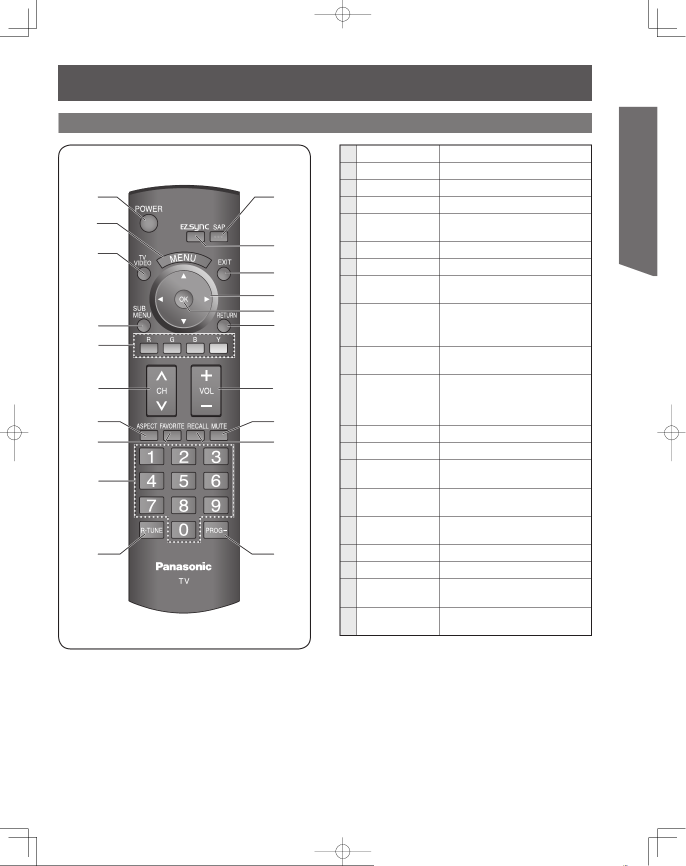
Remote Control
1
2
3
4
5
6
7
8
9
10
11
12
13
14
15
16
17
18
19
20
1
POWER Press to turn ON and OFF.
2
MENU Press to display Main Menu.
3
TV/VIDEO Changes Input source.
4
SUB MENU Press to display the Sub Menu.
5
FUNCTION
<
6
7
8
>
CH
ASPECT Changes display aspect ratio.
FAVORITE
Press to use for various
functions.
Press to change channels.
Press to operate the Favorite
channel list function.
Press numeric keypad to
9
NUMBER
select any channel or to make
alpha-numeric entries in menus.
10
R-TUNE
Press to switch to previously
viewed channel or input modes.
In analog mode, press to access
11
SAP
audio modes (Stereo, SAP or
Mono). In digital mode, press to
access next audio track.
12
EZ Sync Press to display EZ Sync menu.
13
EXIT Press to exit menus.
14
SELECT▲▼◄►
15
OK
16
RETURN
17
VOL -+ Press to adjust TV sound.
18
MUTE Press to mute sound.
19
RECALL
20
PROG-
Controls navigation around
on-screen menu.
Press to select menu and
sub-menu items.
Press to return one step
backward in menus.
Press to display or delete
Channel banner.
Press after entering a digital
channel to enter a sub-channel.
Getting Start ed
9
Location of Controls (continued)
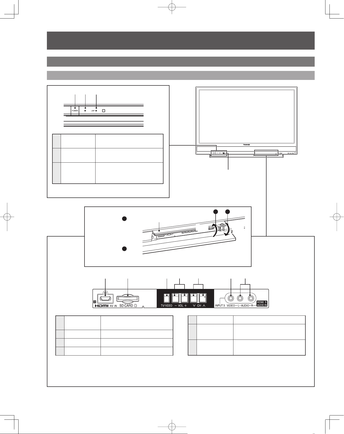
Controls and Terminals on the Projection Display
Front View <Model PT-56LCX70 unit shown>
12 3
POWER
1
button
POWER
2
indicator
LAMP
3
indicator
Press to turn ON and OFF.
(p. 24, 56, 57)
Lights up green when power
is ON. (p. 24, 56, 57)
Lights up or flashes when the
lamp unit is malfunctioning.
(p. 24, 56)
Open Door:
Press position 1, and
slide Door open as
shown by arrow.
Close Door:
Press position 2, and
slide Door closed as
shown by arrow.
12 34 576
Door
Remote Control
Sensor
1 2
Open
Close
10
>
HDMI Input
1
Terminal 3
2
SD CARD Slot Insert SD Card.
3
TV/VIDEO* Changes Input source.
4
VOL –+* Press to adjust TV sound.
* Buttons listed above operate the same as Remote Control buttons of the same name.
Connect from other
component. (HDMI 3)
5
6
7
<
CH
* Press to change channels.
Video Input
Connector 3
Audio Input
Connector 3
Connect from other
component. (Video 3)
Connect from other
component. (Video 3 / HDMI 3)
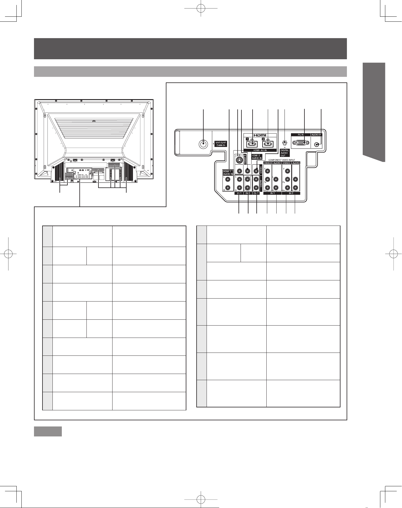
Rear View <Model PT-56LCX70 unit shown>
12345678910
Getting Start ed
Vent
1
VHF/UHF Cable In
HDMI Input
2
Terminal 1
S Video/Video Input
3
Connector 1
Video Input
4
Connector 2
HDMI Input
5
Terminal 1
HDMI Input
6
Terminal 2
Video Out
7
Connector
DIGITAL AUDIO
8
OUT
PC (RGB) Input
9
Connector
Audio Input
10
Connector
Audio 1
Audio/
Video 1
Audio/
Video 2
Vent
Input terminal for an
antenna or cable box
signal.
Connect from other
component. (HDMI 1)
Connect from other
component. (Video 1)
Connect from other
component. (Video 2)
Connect from other
component. (HDMI 1)
Connect from other
component. (HDMI 2)
Output video signal.
Output audio signal
(Digital)
Connect from PC. (PC)
Connect from PC. (PC)
11 15 16
Audio Input
11
Connector 1
HDMI Input
Terminal 2
12
Audio Input
Connector 2
Audio Out
13
Connector
Component Video
14
Input Connector 1
Audio Input
15
Connector 1
Component Video
16
Input Connector 2
Audio Input
17
Connector 2
1312 14 17
Connect from other
component. (Video 1)
Audio 2
Connect from other
component. (HDMI 2)
Connect from other
component. (Video 2)
Output audio signal.
(Analog)
Connect from other
component.
(Component 1)
Connect from other
component.
(Component 1)
Connect from other
component.
(Component 2)
Connect from other
component.
(Component 2)
Notes
Make sure the vents are not blocked. (This could cause damage.)
•
Indication on the back panel may change without notice.
•
11
Installation
Connected Equipment Introduction
(Signal source)
Watching TV
■
VHF/UHF Antenna
NTSC (National Television System Committee): Conventional
•
broadcasting
ATSC (Advanced Television Systems Committee): Digital TV
•
Standards include digital high-definition television (HDTV),
standard-definition television (SDTV), data broadcasting,
multi-channel surround-sound audio and interactive
television.
Cable Box/Cable
You need to subscribe to a cable TV service to enjoy viewing
•
their programming.
You can enjoy high-definition programming by subscribing to
•
a high-definition cable service. The connection can be done
with the use of HDMI or Component Video cable.
or
or
VHF/UHF Antenna Cable Box/Cable
VHF/UHF Antenna Cable Box/Cable
Recording/playing back with DVD recorder or
■
VCR
DVD Recorder
This source has higher resolution through interlace or
progressive signal. Connection can be done with the use of
Component Video or HDMI cable.
VCR
Connection can be done with the use of an RF cable and
Composite Video/S VIDEO.
Enjoying Home theater and DVD recorder with
■
HDMI connection
Home theater and DVD Recorder
HDMI connection enables you to enjoy higher quality audio and
video with a single cable.
Home Theater DVD RecorderHome Theater DVD Recorder
Enjoying large screen capabilities with PC
■
connection
You can enjoy playing computer games or making
presentations on a large screen with the PC connection.
PCPC
Notes
If your Panasonic DVD Recorder is compatible with EZ Sync
•
(HDAVI control 2), you can operate your Panasonic DVD
Recorder with this Projection Display’s remote control (EZ
Sync™ on page 34).
All cables and external equipment shown in this book are not
•
supplied with this Projection Display.
For the details of the external equipment’s connections,
•
please refer to the operating manuals for the equipment.
Reference of connection
12
or
or
DVD Recorder VCR
DVD Recorder VCR
Watching Satellite
■
You can enjoy high-definition programming by subscribing to a
high-definition satellite service. Connection can be done with
the use of HDMI or Component Video cable.
Satellite Receiver
Satellite Antenna
Satellite Antenna
Satellite Receiver
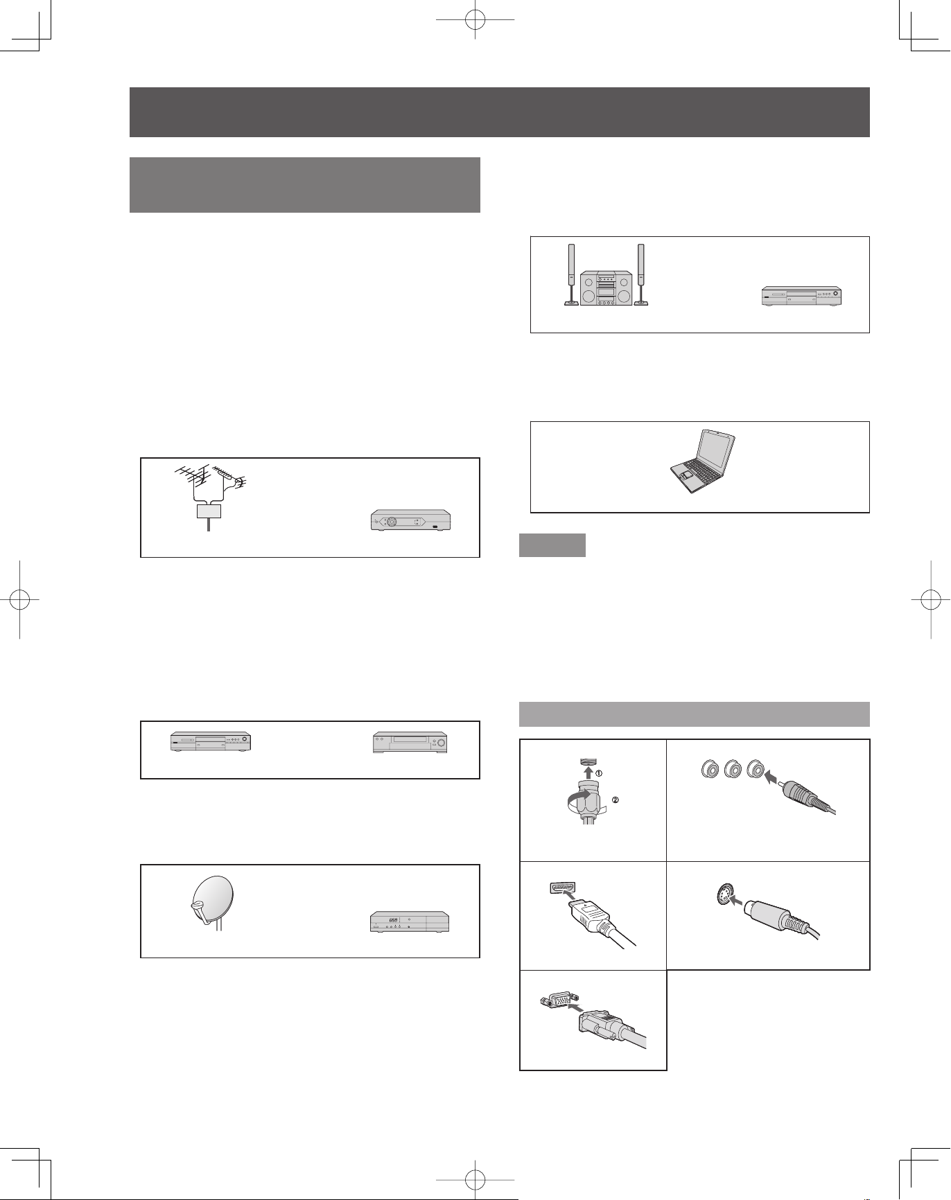
Antenna terminal■ Pin terminals■
Antenna terminal■ Pin terminals■
Firmly tighten by hand.•
Firmly tighten by hand.•
HDMI terminal■ S VIDEO terminal■
HDMI terminal■ S VIDEO terminal■
Insert firmly.• Insert firmly.•
Insert firmly.• Insert firmly.•
PC terminal■
PC terminal■
Insert firmly.•
Insert firmly.•
red blue green
red blue green
red blue green
red blue green
green
green
green
green
•
•
Match colors of plugs and terminals.
Match colors of plugs and terminals.
Insert firmly.
•
Insert firmly.
•
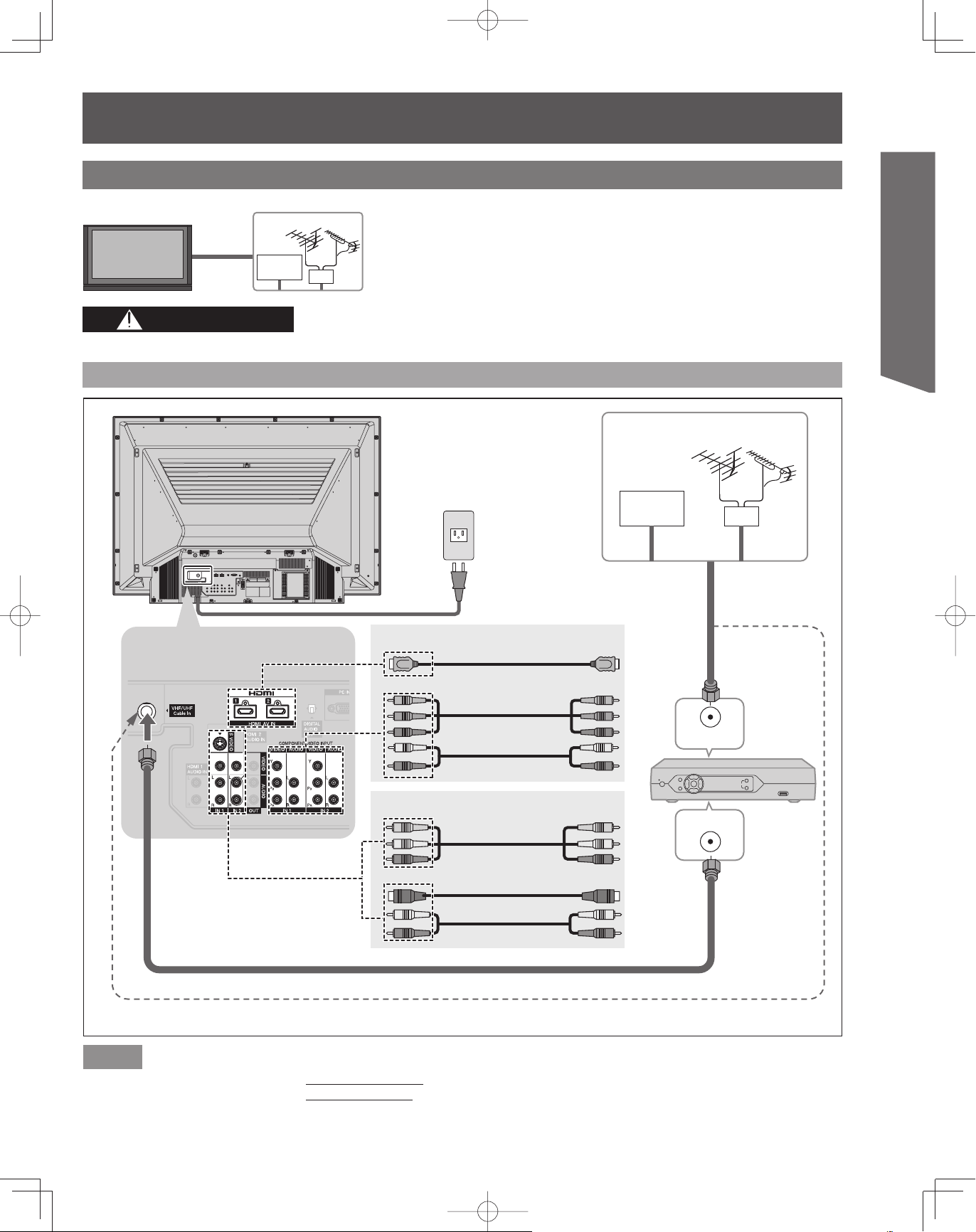
Example 1 Connecting Antenna (To watch TV)
Projection Display
VHF/UHF Antenna
Cable
TV
CAUTION
When using “Nut type” RF coaxial cable, tighten with fingers only. Overtightening may damage terminal.
To connect antenna terminals
Back of the unit
VHF/UHF Antenna
AC 120 V
60 Hz
Power Cord
(Connect after all the
other connections.)
Cable TV
or
Getting Start ed
For HDTV Cable Service
Antenna terminal
For Digital Cable
To use HDMI terminals
or
To use COMPONENT
terminals
To use COMPOSITE
terminals
To use S VIDEO
or
terminals
If using Cable Box :
Set the TV channel to CH3, CH4, or select the appropriate input.
or
ANT IN
ANT OUT
(If no Cable Box)
Cable Box
Note
For additional assistance, visit us at : www.panasonic.com
•
www.panasonic.ca
13
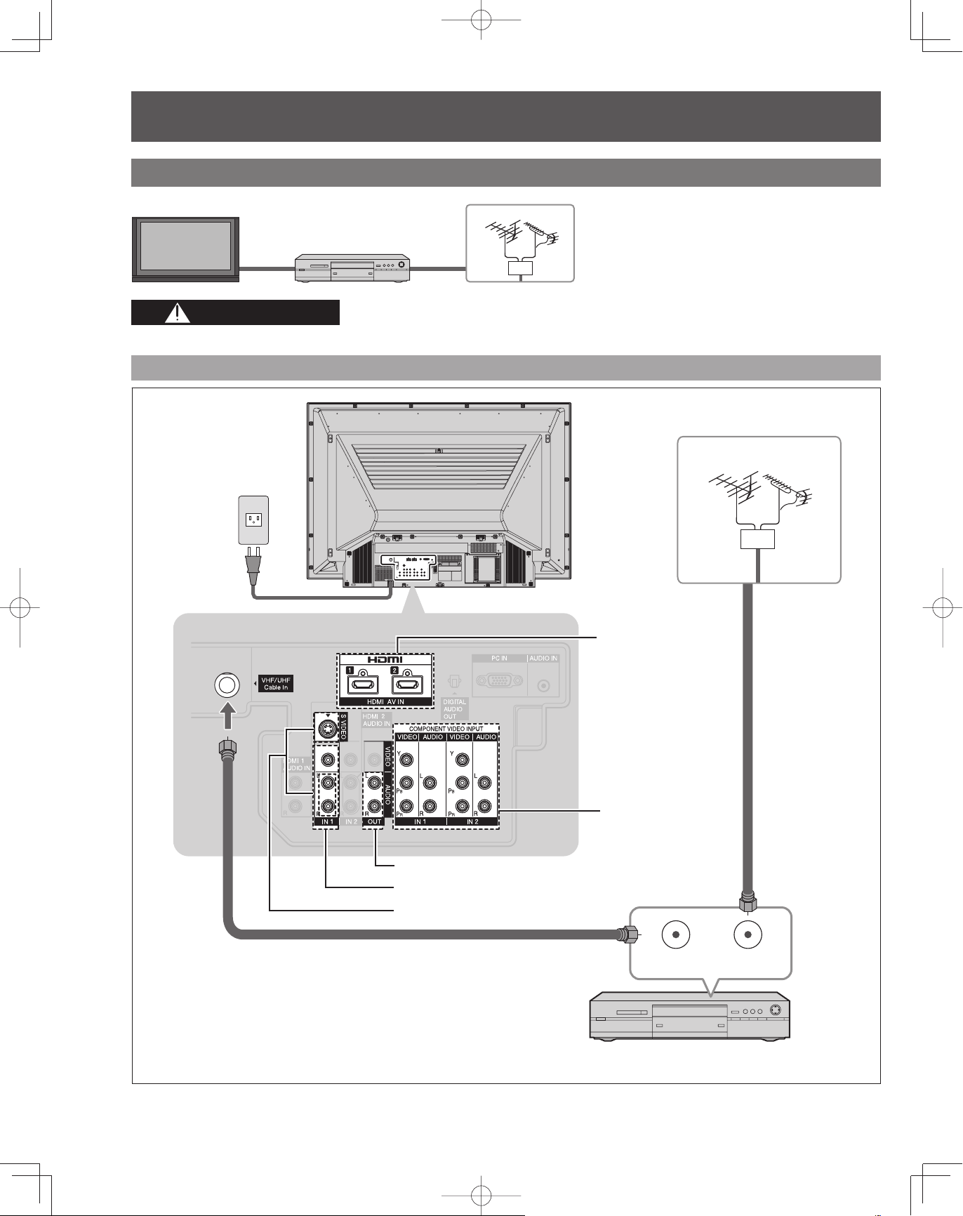
Installation (continued)
Example 2 Connecting DVD recorder (VCR) (To record/playback)
Projection Display
DVD Recorder
or
VCR
VHF/UHF Antenna
CAUTION
When using “Nut type” RF coaxial cable, tighten with fingers only. Overtightening may damage terminal.
To connect antenna terminals
Back of the unit
VHF/UHF Antenna
AC 120 V
60 Hz
Power Cord
Antenna terminal
To use HDMI
terminals (next page)
To use COMPONENT
terminals (next page)
To use OUTPUT terminals (p. 21, 22)
To use COMPOSITE terminals (next page)
To use S VIDEO terminals (next page)
ANT OUT ANT IN
14
DVD Recorder or VCR
(with TV tuner)
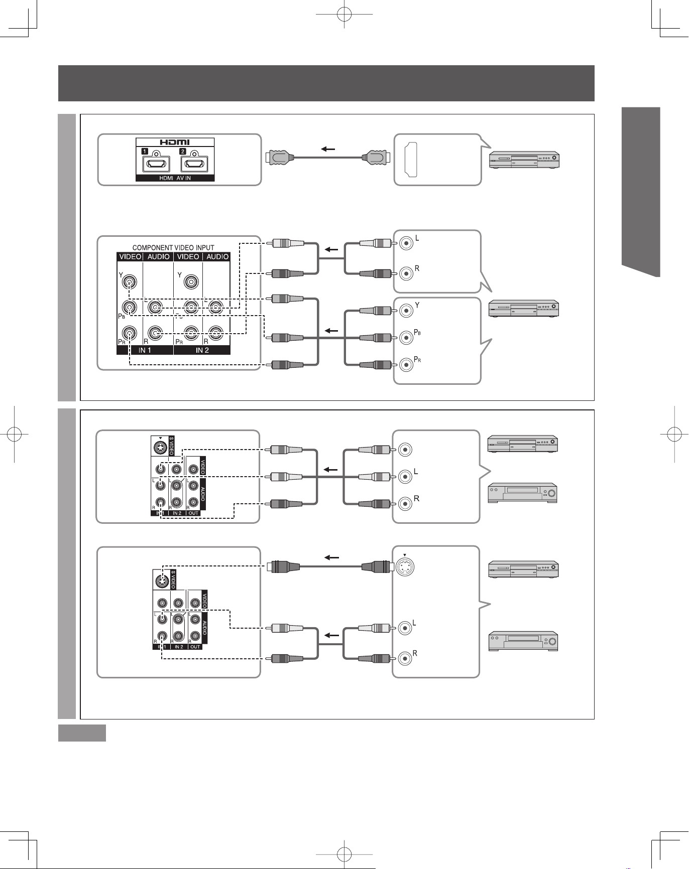
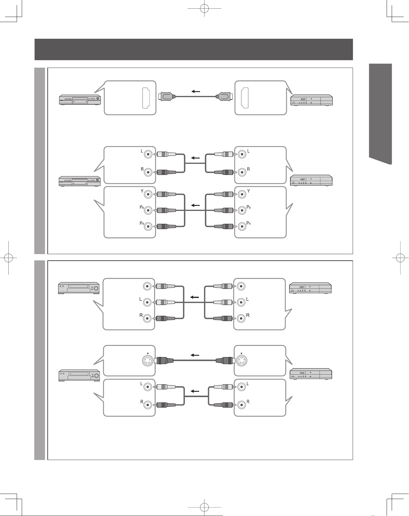
To use HDMI terminals■
HDMI
AV OUT
Connecting to HDMI terminals will enable you to enjoy high-definition digital images and high-quality sound by connecting
•
this Projection Display and the devices.
DVD Recorder, Blu-ray Disc
Player, DTV STB, etc
To use COMPONENT terminals■
white
white
white
AUDIO OUT
Getting Start ed
High-DefinitionStandard-Definition
Recorders may also be connected to COMPOSITE or S VIDEO terminals. (see below.)•
To use COMPOSITE terminals■
To use S VIDEO terminals■
red
green
blue
red
yellow yellow
white white
red
red
green
blue
red
red
red
green
blue
red
yellow
white
red
COMPONENT
VIDEO OUT
COMPOSITE
OUT
S VIDEO
OUT
DVD Recorder, Blu-ray Disc
Player, DTV STB, etc
DVD Recorder
or
VCR
DVD Recorder
or
white white
red red
The S Video input will override the composite video
• Connecting to S VIDEO terminals will enable you to enjoy
signal when S Video cable is connected. Connect
either S Video or Video cable.
•
greater picture quality than using Composite terminals.
white
red
AUDIO
OUT
VCR
Notes
Some programs contain a copyright protection signal to prevent recording.
•
When the copyright protection program is displayed, do not connect the other TV monitor through a VCR. Video signals fed through
•
VCRs may be affected by copyright protection systems and the picture will be distorted on the other TV monitor.
15
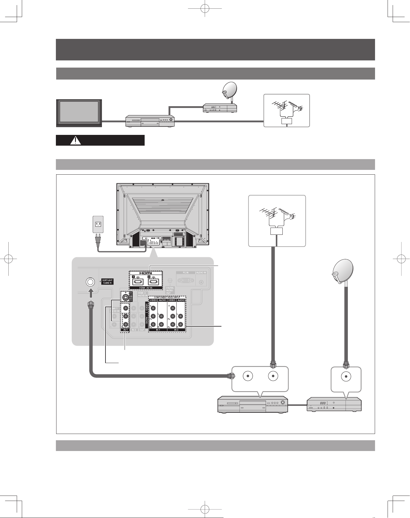
Installation (continued)
Example 3 Connecting DVD recorder (VCR) and satellite receiver
Projection Display
DVD Recorder
or
VCR
Satellite
Receiver
VHF/UHF Antenna
CAUTION
When using “Nut type” RF coaxial cable, tighten with fingers only. Overtightening may damage terminal.
To connect antenna terminals
Back of the unit
AC 120 V
60 Hz
Power Cord
Antenna terminal
To use HDMI
terminals
(p. 15)
VHF/UHF Antenna
16
To use
COMPONENT
terminals
(p. 15)
To use COMPOSITE terminals (p. 15)
To use S VIDEO terminals (p. 15)
ANT OUT ANT IN
DVD Recorder or VCR
(with TV tuner)
Connecting this Projection Display and DVD recorder (VCR)
Connect in the same way as on page 15.
ANT IN
DTV Satellite Receiver
or
DTV Cable Receiver
To use HDMI terminals■
HDMI
AV IN
DVD Recorder
Connecting to HDMI terminals will enable you to enjoy high-definition digital images and high-quality sound.•
To use COMPONENT terminals■
white
AUDIO IN
DVD Recorder
COMPONENT
VIDEO IN
white
red
green
blue
red
red
green
blue
red
To connect DVD recorder and satellite receiverTo connect VCR and satellite receiver
Satellite Receiver may also be connected to COMPOSITE or S VIDEO terminals. (see below.)•
white
red
green
blue
red
white
red
green
blue
red
HDMI
AV OUT
Satellite Receiver
or
Cable Receiver
Getting Start ed
AUDIO OUT
Satellite Receiver
or
Cable Receiver
COMPONENT
VIDEO OUT
To use COMPOSITE terminals■
VCR
yellow
COMPOSITE
IN
yellow yellow
white white
white
red red
red
yellow
white
red
COMPOSITE
OUT
Satellite Receiver
or
Cable Receiver
To use S VIDEO terminals■
S VIDEO
IN
VCR
AUDIO
IN
The S Video input will override the composite video
• Connecting to S VIDEO terminals will enable you to enjoy
signal when S Video cable is connected. Connect
either S Video or Video cable.
white white
white
red red
red
white
•
greater picture quality than using Composite terminals.
red
S VIDEO
OUT
AUDIO
OUT
Satellite Receiver
or
Cable Receiver
17
Installation (continued)
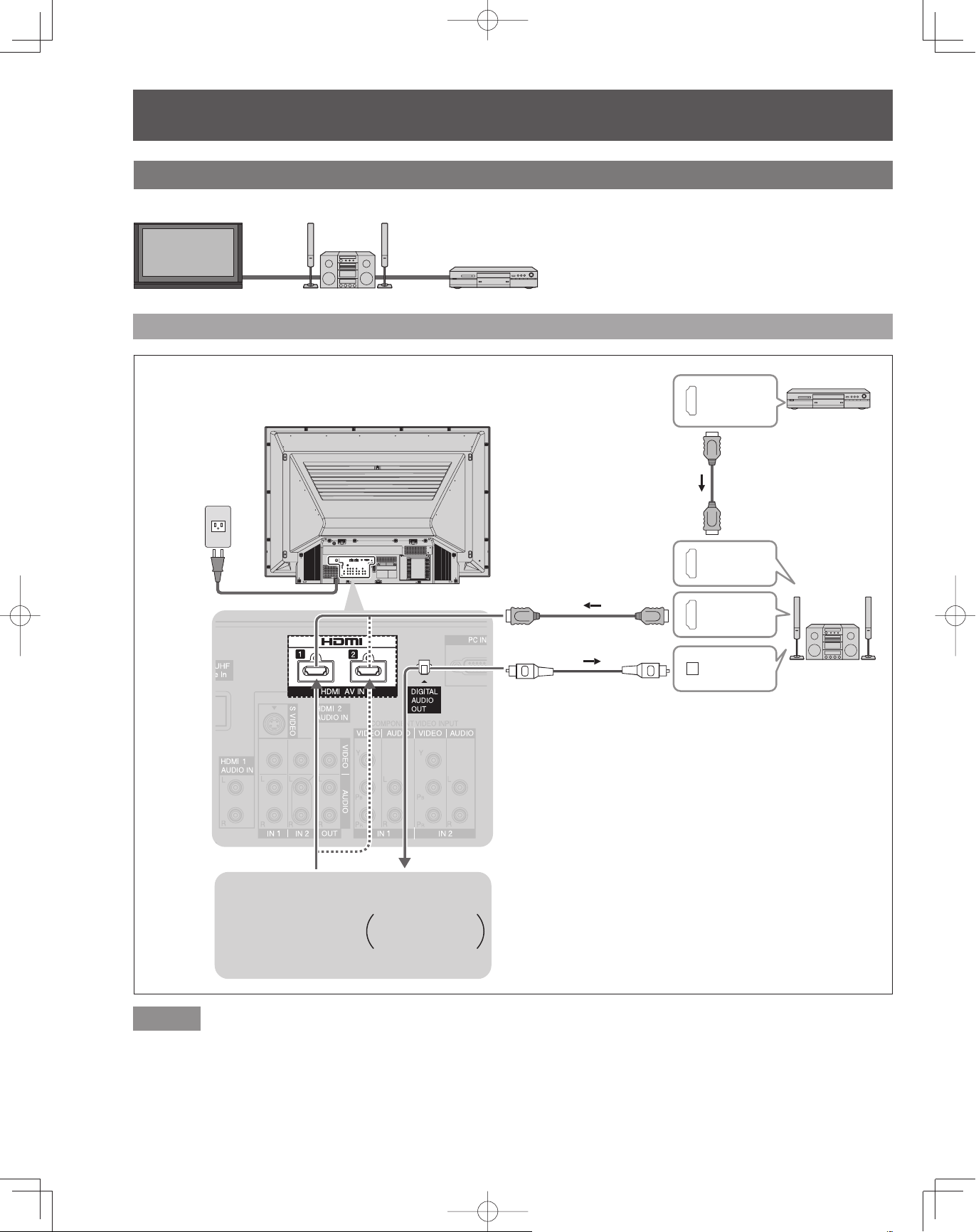
Example 4 Connecting Home Theater and DVD recorder
Projection Display Home Theater
DVD Recorder
To connect HDMI terminals
Back of the unit
AC 120 V
60 Hz
HDMI
AV OUT
DVD Recorder
Power Cord
or
Home theater
(HDMI AV OUT)
Home theater
(DIGITAL AUDIO IN)
When listening to
TV audio
[ATSC only]
HDMI
AV IN
HDMI
AV OUT
DIGITAL
AUDIO IN
Home Theater
(AV amp)
18
Notes
It is recommended that you use Panasonic’s HDMI cable. (p. 52)
•
When Using the COMPONENT VIDEO OUT terminals or the S VIDEO OUT terminal, refer to page 17 “To use COMPONENT
•
terminals” or “To use S VIDEO terminals”.
If you connect RAM theater or Player theater with HDMI cable, use audio cable instead of the optical digital audio cable. (p. 22)
•
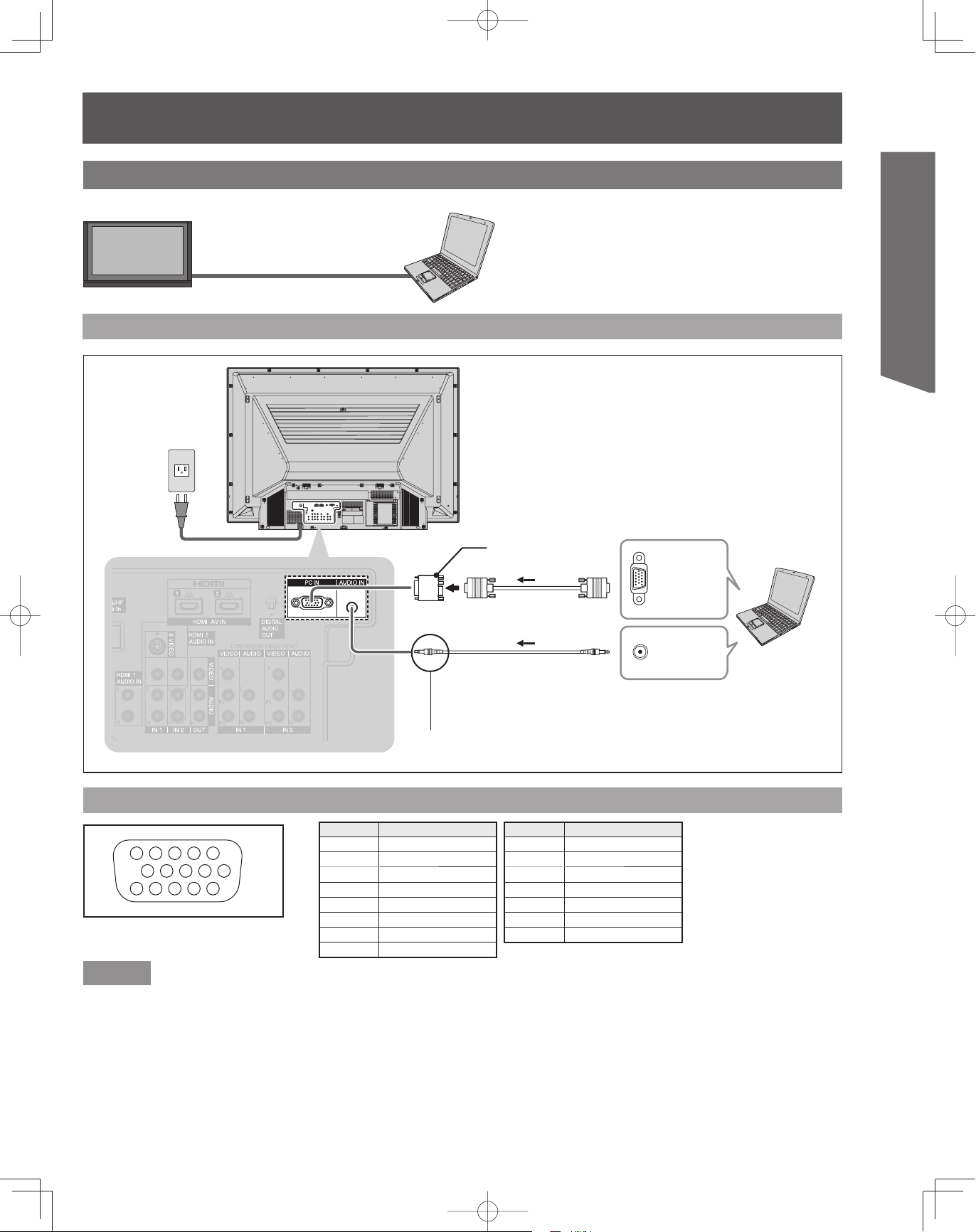
Example 5 Connecting PC
Projection Display
To connect PC terminals
Back of the unit
AC 120 V
60 Hz
Power Cord
PC
Conversion adapter
(If necessary)
RGB cable (D-SUB 15P)
(Not included)
PC audio cable
(M3 stereo mini pin)
MONITOR
OUT
AUDIO
OUT
Getting Start ed
PC
Connect a cable which matches the audio output
terminal on the computer.
PC IN Terminal (D-SUB 15P) Pin Layouts
Pin No. Signal name
45
10
15 14 13 12 11
Connection port view
1
2
67839
1R
2G
3B
4NC
5NC
6 Ground for R
7 Ground for G
8 Ground for B
Notes
Some PC models cannot be connected to the set. A conversion adapter is required to use the RGB cable (D-SUB 15P) (Not
•
included) to connect a Macintosh computer to the set. There is no need to use an adapter for computers with PC / AT compatible
D-SUB 15P terminal.
The computer shown in the illustration is for example purposes only. Additional equipment and cables shown are not supplied with
•
this set.
Do not set the horizontal and vertical scanning frequencies for PC signals which are above or below the specified frequency range.
•
Select the desired PC input position by pressing the TV/VIDEO button on the Remote Control. (p. 29)
•
Pin No. Signal name
9NC
10 Ground
11 NC
12 NC
13 HD/CSYNC
14 VD
15 NC
NC: Not connected
19
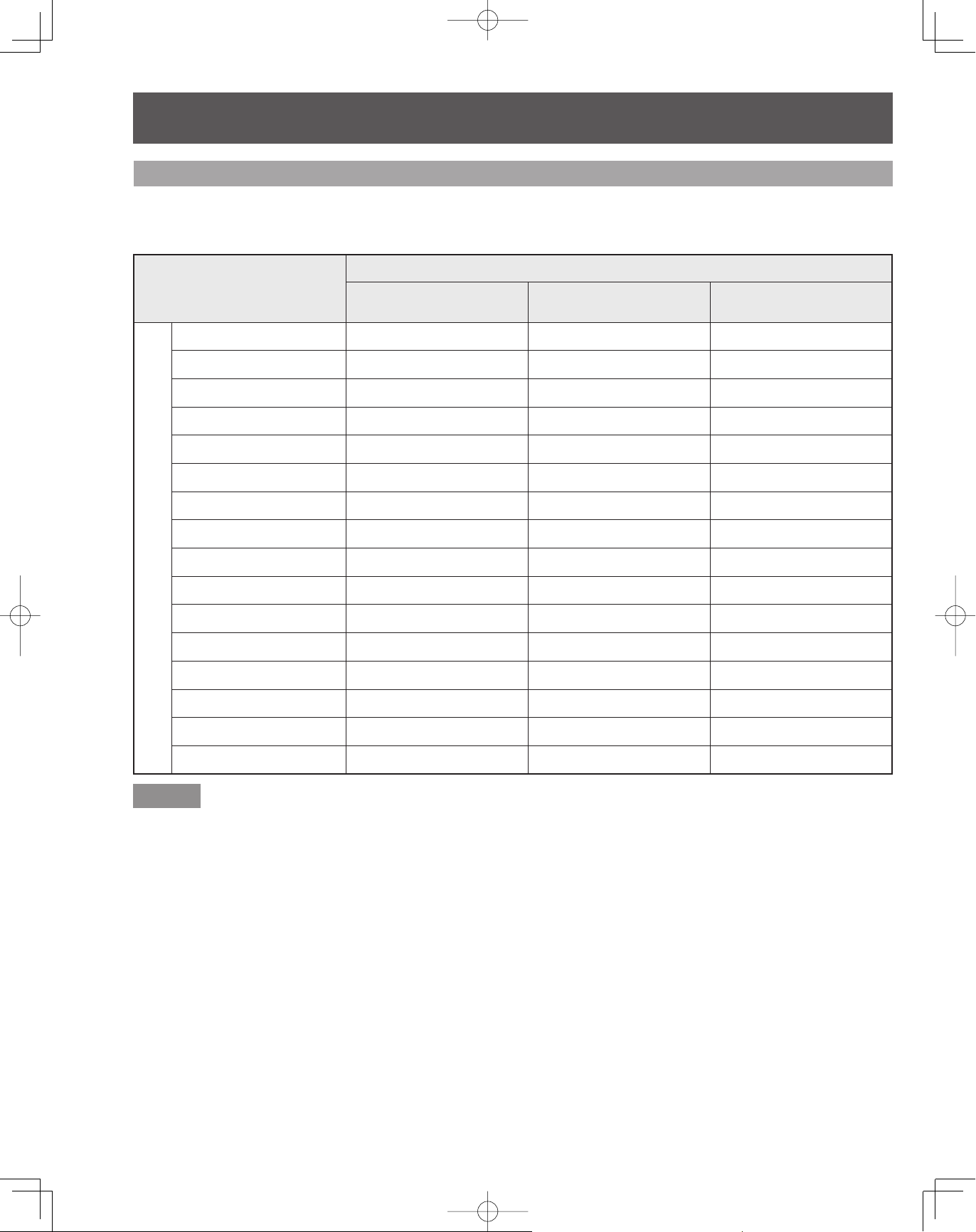
Installation (continued)
RGB signals that can be input
The table below lists the different types of RGB signals that can be input.
If a signal which differs greatly from the types listed below is input, the picture may not be displayed correctly,
or a black background may be displayed.
Signal data
Mode type
VGA400 (70 Hz) 640 × 400 31.47 70.08
VGA480 (60 Hz) 640 × 480 31.47 59.94
Macintosh 13˝ * 640 × 480 35.00 66.67
VGA480 (75 Hz) 640 × 480 37.50 75.00
SVGA (60 Hz) 800 × 600 37.88 60.32
SVGA (75 Hz) 800 × 600 46.88 75.00
SVGA (85 Hz) 800 × 600 53.67 85.06
Macintosh 16˝ * 832 × 624 49.73 74.55
No. of dots
(H × V)
Horizontal frequency
(kHz)
Vertical frequency
(Hz)
WVGA (60 Hz) 852 × 480 31.47 59.94
XGA (60 Hz) 1 024 × 768 48.36 60.00
Personal Computer Signals
XGA (70 Hz) 1 024 × 768 56.48 70.07
XGA (75 Hz) 1 024 × 768 60.02 75.03
XGA (85 Hz) 1 024 × 768 68.67 85.00
Macintosh 21˝ * 1 152 × 870 68.68 75.06
SXGA (60 Hz) 1 280 × 1 024 63.98 60.02
WXGA (60 Hz) 1 366 × 768 48.39 60.04
Notes
The D-SUB 15P connector can accept RGB (H-V sync separate).
•
The signal with a * mark is compatible with sync on Green.
•
To view a WXGA and WVGA picture, a setting change is necessary. Please refer to “PC Adjust” on page 37.
•
20
 Loading...