

Panasonic PT-60LCX63, PT-50LCX63 Owner’s Manual
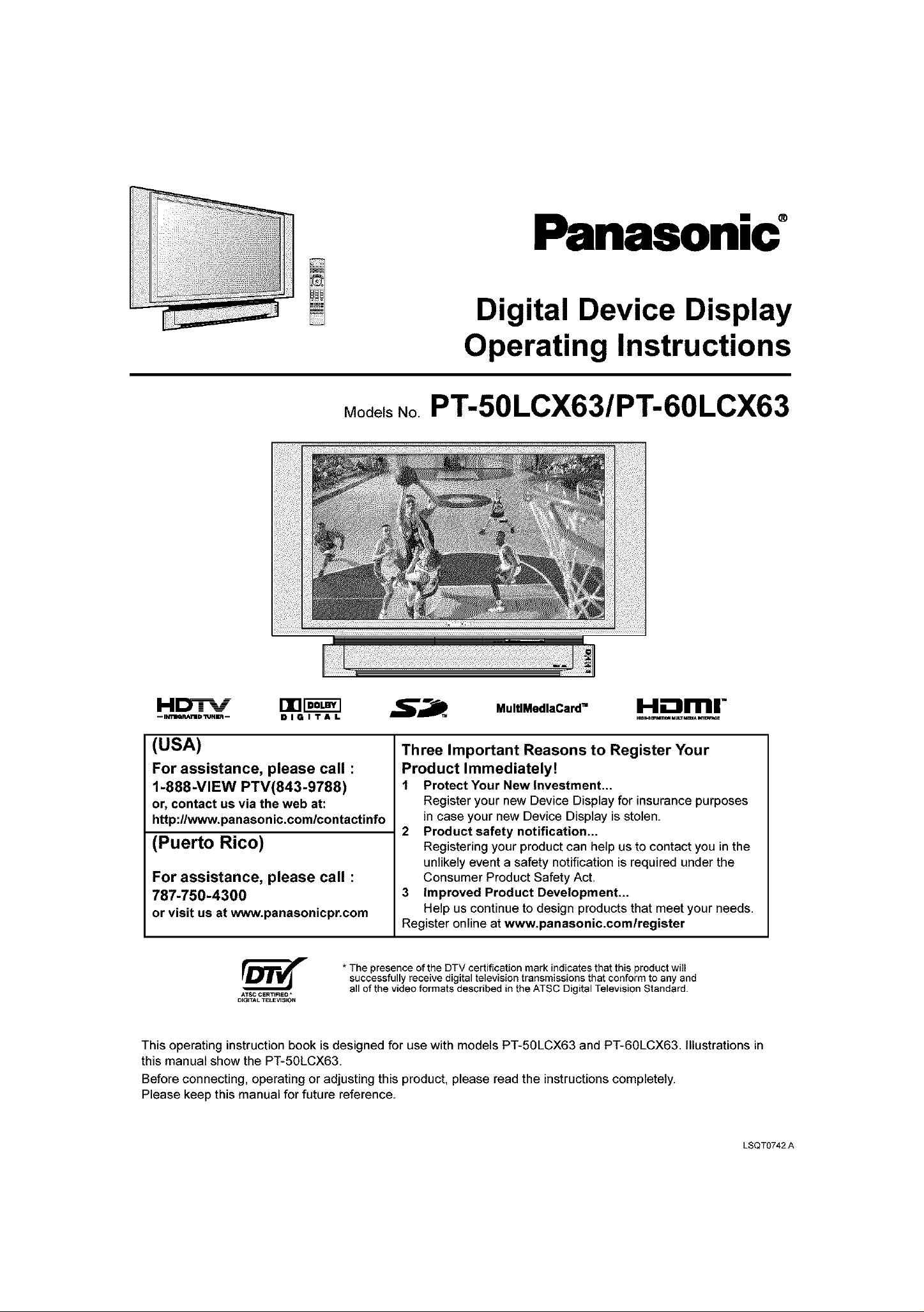
Panasonic
Digital Device Display
Operating Instructions
Models No PT-50LCX63/PT-60LCX63
--Ima.u_TUDI"JNn-- D I G I T A L
(USA)
For assistance, please call :
1-888-VIEW PTV(843-9788)
or, contact us via the web at:
http://www.panasonic.com/contactinfo
(Puerto Rico)
For assistance, please call :
787-750-4300
or visit us at www.panasonicpr.com
* The presence of the DTV certification mark indicates that this product will
successfully receive digital television transmissions that conform to any and
ATSC CERT_RED *
DIGITAL TELEV_S;ON
This operating instruction book is designed for use with models PT-50LCX63 and PT-60LCX63. Illustrations in
this manual show the PT-50LCX63.
Before connecting, operating or adjusting this product, please read the instructionscompletely.
Please keep this manual for future reference.
all of the video formats described in the ATSC Digital Television Standard.
Three Important Reasons to Register Your
Product Immediately!
1 Protect Your Newlnvestment,,,
Register your new Device Display for insurance purposes
in case your new Device Display is stolen.
2 Product safety notification...
Registering your product can help us to contact you in the
unlikely event a safety notification is required under the
Consumer Product Safety Act.
3 Improved Product Development...
Help us continue to design products that meet your needs.
Register online at www.panasonic.comlregister
MultlMedlaCard TM H.'-amr
LSQT0742 A
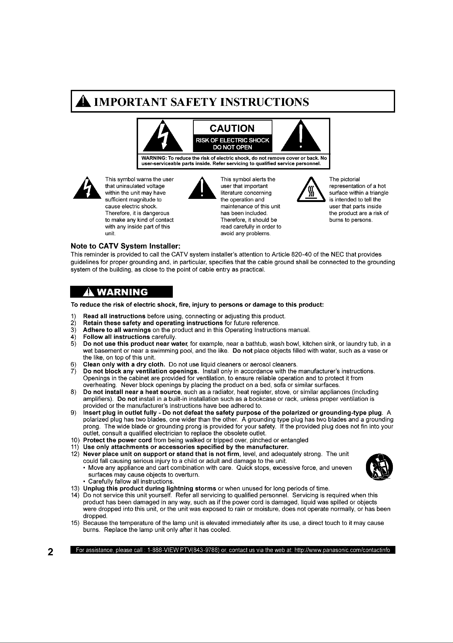
A IMPORTANT SAFETY INSTRUCTIONS
CAUTION
WARNING: To reduce the risk of electric shock, do not remove cover or beck. No
user-serviceable parts inside. Refer servicing to qualified service personnel.
I
This symbol warns the user
that uninsulated voltage
within the unit may have
sufficient magnitude to
cause electric shock.
Therefore, it is dangerous
to make any kind of contact
with any inside part of this
unit.
Note to CATV System Installer:
This reminder is provided to call the CATV system installer's attention to Article 820-40 of the NEC that provides
guidelines for proper grounding and, in particular, specifies that the cable ground shall be connected to the grounding
system of the building, as close to the point of cable entry as practical.
To reduce the risk of electric shock, fire, injury to persons or damage to this product:
1) Read all instructions before using, connecting or adjusting this product.
2) Retain these safety and operating instructions for future reference.
3) Adhere to all warnings on the product and in this Operating Instructions manual.
4) Follow all instructions carefully.
5) Do not use this product near water, for example, near a bathtub, wash bowl, kitchen sink, or laundry tub, in a
wet basement or near a swimming pool, and the like. Do not place objects filled with water, such as a vase or
the like, on top of this unit.
6) Clean only with a dry cloth. Do not use liquid cleaners or aerosol cleaners.
7) Do not block any ventilation openings. Install only in accordance with the manufacturer's instructions.
Openings in the cabinet are provided for ventilation, to ensure reliable operation and to protect it from
overheating. Never block openings by placing the product on a bed, sofa or similar surfaces.
8) Do not install near a heat source, such as a radiator, heat register, stove, or similar appliances (including
amplifiers). Do not install in a built-in installation such as a bookcase or rack, unless proper ventilation is
provided or the manufacturer's instructions have bee adhered to.
9) Insert plug in outlet fully - Do not defeat the safety purpose of the polarized or grounding-type plug. A
polarized plug has two blades, one wider than the other. A grounding type plug has two blades and a grounding
prong. The wide blade or grounding prong is provided for your safety, if the provided plug does not fin into your
outlet, consult a qualified electrician to replace the obsolete outlet.
10) Protect the power cord from being walked or tripped over, pinched or entangled
11) Use only attachments or accessories specified by the manufacturer.
12) Never place unit on support or stand that is not firm, level, and adequately strong. The unit
could fall causing serious injury to a child or adult and damage to the unit
• Move any appliance and cart combination with care. Quick stops, excessive force, and uneven
surfaces may cause objects to overturn.
• Carefully fallow all instructions.
13) Unplug this product during lightning storms or when unused for long periods of time
14) Do not service this unit yourself Refer all servicing to qualified personnel Servicing is required when this
product has been damaged in any way, such as ifthe power cord is damaged, liquid was spilled or objects
were dropped into this unit, or the unit was exposed to rain or moisture, does not operate normally, or has been
dropped.
15) Because the temperature of the lamp unit is elevated immediately after its use, a direct touch to it may cause
burns. Replace the lamp unit only after it has cooled.
,_ This symbol alertsthe
user that important
literature concerning
the operation and
maintenance of this unit
has been included.
Therefore, it should be
read carefully in order to
avoid any problems.
The pictorial
representation of a hot
surface within a triangle
is intended to tell the
user that parts inside
the product are a risk of
burns to persons.
2
A IMPORTANT SAFETY INSTRUCTIONS (CONTINUED)I
AS WITH ANY SMALL OBJECT, SD CARDS CAN BE SWALLOWED BY YOUNG CHILDREN. DO NOT ALLOW
CHILDREN TO HANDLE THE SD CARD.
(1) This Device Display is intended to be used with the following TV stand: model TY-50LC13C for the
PT-50LCX63/PT-60LCX63. Use with other stands may result in the Device Display becoming unstable, possibly
causing injury.
(2) This Device Display should not be exposed to direct sunlight, extreme temperatures or moisture, as this can result
in serious irreparable damage.
(3) This product has a High intensity Discharge (HID) lamp that contains a small amount of mercury. It also contains
lead in some components.
Disposal of these materials may be regulated in your community due to environmental considerations.
For disposal or recycling information please contact your local authorities, or the Electronics Industries Alliance:
<http:llwww.eiae.ora.>
Trademarks
• VGA and XGA are trademarks of International Business Machines Corporation.
• Macintosh is a registered trademark of Apple Computer, USA.
• VESA and SVGA are trademarks of the Video Electronics Standard Association,
Even if no special notation has been made of company or product trademarks, these trademarks have been fully respected.
• Equipped with dlH°-TV Noise Reduction for true MTS reproduction, dI_°-TV Noise Reduction is required for good stereo
separation and audio fidelity, dl_° is a registered trademark, and is licensed by dl==• Technology Licensing,
SD Logo is a trademark.
Manufactured under license from BBE Sound, Inc
Licensed by BBE Sound, Inc. under USP4638258 and 4482866.
H/ghDef/n/t/on Sound
BBE and BBE symbol are registered trademarks of BBE Sound, Inc.
H-"=rnl" HDMI, the HDMI logo and High Definition Multimedia Interface
............................ are trademarks or registered trademarks of HDMI Licensing LLC
This product incorporates copyright protection technology that is protected by U.S patents and other intellectual
property rights. Use of this copyright protection technology must be authorized by Macrovision Corporation, and
is intended for home and other limited viewing uses only unless otherwise authorized by Macrovision. Reverse
engineering or disassembly is prohibited.
U.S. Patents Nos. 4,631,603; 4,577,216; 4,819,098; 4,907,093; 6,381,747; and 6,516,132.
3
Dear Panasonic Customer
Welcome to the Panasonie family of customers. We hope that you will have many years of en]oyment,_om your new
Device Display.
To obtain maximum benefit,_'om your set, please read these Instructions before making any adjustments, and retain
them for future reference.
Retain your purchase receipt also, and record the serial number of your set in the space provided on the rear cover
of these instructions.
Visit our Panasonic Web Site for USA : www:panasonic.com
(USA)
For assistance, please call : 1-888-VIEW PTV(843-9788)
or, contact us via the web at: http://www.panasonic.com/contactinfo
(Puerto Rico)
For assistance, please call : 787-750-4300
or visit us at www.panasonicpr.com
FCC STATEMENT:
NOTE:
This equipment has been tested and found to comply with the limits for a Class B digital device, pursuant to Part 15
ofthe FCC Rules These limitsare designed to provide reasonable protection against harmful interference in a
residential installation. This equipment generates, uses and can radiate radio frequency energy and, ifnot installed
and used in accordance with the instructions, may cause harmful interference to radio communications. However,
there is no guarantee that interference will not occur in a particular installation. Ifthis equipment does cause harmful
interference to radio or television reception, which can be determined by turning the equipment off and on, the user
is encouraged to try to correct the interference by one or more of the following measures:
• Reorient orrelocatethe receiving antenna,
• Increase the separation between the equipment and receiver.
• Connect the equipment into an outlet on a circuit different from that to which the receiver isconnected.
• Consult the dealer or anexperienced radio/ TV technician for help.
FCC CAUTION:
To assure continued compliance and prevent undesirable interference, use only the provided shielded RGB cable
with 2 ferrite cores while connecting the Device Display to a computer. Any changes or modifications not expressly
approved by the party responsible for compliance could void the user's authority to operate this equipment.
ANY CHANGES OR MODIFICATIONS TO THIS PTV RECEIVER NOT EXPRESSLY APPROVED BY MATSUSHITA
ELECTRIC CORPORATION OF AMERICA COULD CAUSE HARMFUL INTERFERENCE, WHICH WOULD VOID
THE USER'S AUTHORITY TO OPERATE THIS EQUIPMENT,
r_ The class H insulation symbol (square within a square) indicates that this product has been evaluated
Models Number:
Trade Name:
Responsible party:
Address:
Telephone number:
This device complies with Part 15 of the FCC Rules Operation is subject to the following two conditions: (1) This
device may not cause harmful interference, and (2) this device must accept any interference received, including
interference that may cause undesired operation.
and tested to comply with Class H insulation requirements.
Declaration of Conformity
PT-50LCX63/PT-60LCX63
Panasonic
Matsushita Electric Corporation of America
One Panasonic Way Secaucus New Jersey 07094
1-888-VIEW PTV(843-9788)
4
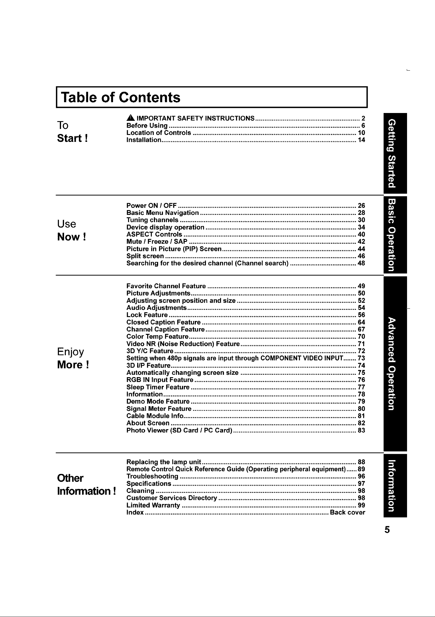
Table of Contents
A IMPORTANT SAFETY INSTRUCTIONS ............................... 2
To
Start !
Use
Now !
Before Using ....................................................... 6
Location of Controls ........................................................................................ 10
Installation. ...................................................... 14
Power ON / OFF .................................................. 26
Basic Menu Navigation ............................................... 28
Tuning channels ................................................... 30
Device display operation ............................................ 34
ASPECT Controls .................................................. 40
Mute / Freeze / SAP ........................................................................................... 42
Picture in Picture (PIP) Screen ......................................................................... 44
Split screen ....................................................................................................... 46
Searching for the desired channel (Channel search) .................................... 48
I
Enjoy
More !
Favorite Channel Feature ............................................. 49
Picture Adjustments .......................................................................................... 50
Adjusting screen position and size ..................................... 52
Audio Adjustments ............................................................................................ 54
Lock Feature ...................................................................................................... 56
Closed Caption Feature ............................................. 64
Channel Caption Feature .................................................................................. 67
Color Temp Feature ........................................................................................... 70
Video NR (Noise Reduction) Feature ............................................................... 71
3D Y/C Feature ................................................... 72
Setting when 480p signals are input through COMPONENT VIDEO INPUT....... 73
3D liP Feature .................................................................................................... 74
Automatically changing screen size .................................... 75
RGB IN Input Feature .............................................. 76
Sleep Timer Feature .......................................................................................... 77
Information ........................................................................................................ 78
Demo Mode Feature ................................................ 79
Signal Meter Feature ......................................................................................... 80
Cable Module Info .............................................................................................. 81
About Screen .................................................... 82
Photo Viewer (SD Card / PC Card) ................................................................... 83
Other
Information !
Replacing the lamp unit ............................................ 88
Remote Control Quick Reference Guide (Operating peripheral equipment)...... 89
Troubleshooting ................................................... 96
Specifications ..................................................... 97
Cleaning ........................................................ 98
Customer Services Directory ........................................................................... 98
Limited Warranty ................................................. 99
Index .................................................................................................... Back cover
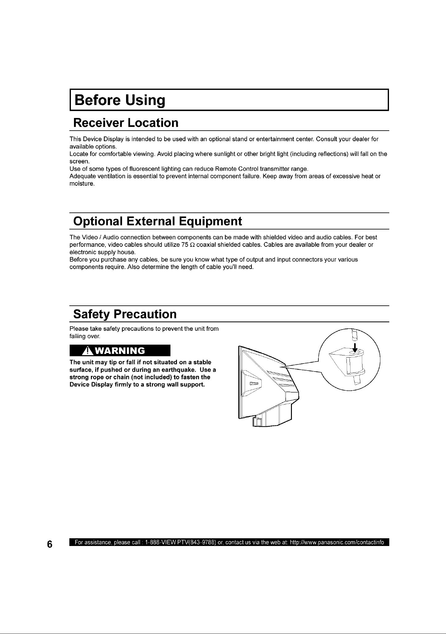
Before Using
Receiver Location
This Device Display is intended to be used with an optional stand or entertainment center. Consult your dealer for
available options.
Locate for comfortable viewing. Avoid placing where sunlight or other bright light (including reflections) will fall on the
screen.
Use of some types of fluorescent lighting can reduce Remote Control transmitter range.
Adequate ventilation is essential to prevent internal component failure. Keep away from areas of excessive heat or
moisture.
Optional External Equipment
The Video / Audio connection between components can be made with shielded video and audio cables. For best
performance, video cables should utilize 75 £2coaxial shielded cables. Cables are available from your dealer or
electronic supply house.
Before you purchase any cables, be sure you know what type of output and input connectors your various
components require. Also determine the length of cable you'll need.
I
Safety Precaution
Please take safety precautions to prevent the unit from
falling over.
The unit may tip or fall if not situated on a stable
surface, if pushed or during an earthquake. Use a
strong rope or chain (not included) to fasten the
Device Display firmly to a strong wall support.
6
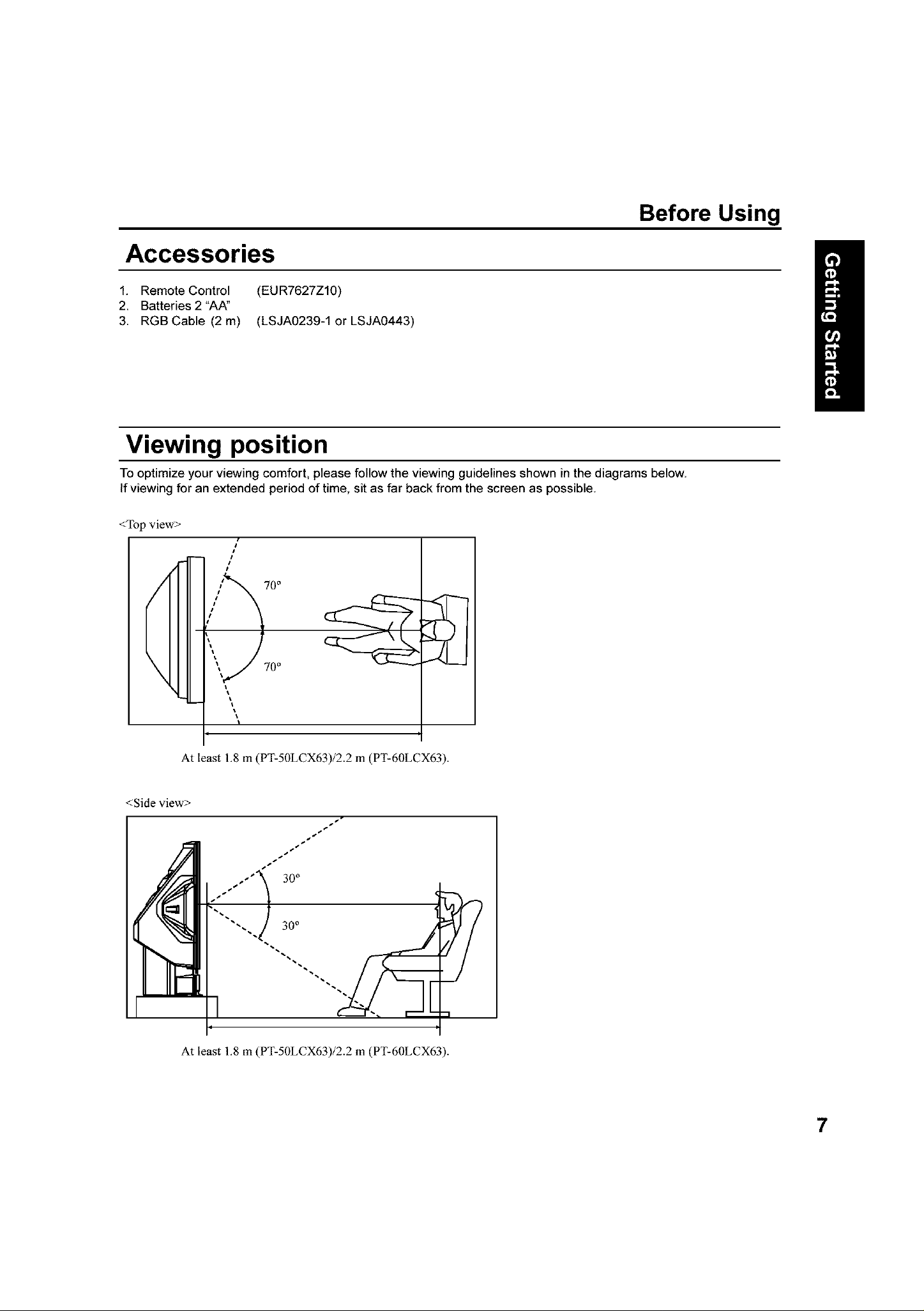
Before Using
Accessories
1. Remote Control (EUR7627Z10)
2. Batteries 2 "AA"
3. RGB Cable (2 m) (LSJA0239-1 or LSJA0443)
Viewing position
To optimize your viewing comfort, please follow the viewing guidelines shown inthe diagrams below.
If viewing for an extended period of time, sit as far back from the screen as possible.
<Top view>
/
#
/
#t
/
i_"x 70°
\
<Side view>
"/" )
'_ 70°
_t
At least 1.8 m (PT-50LCX63)/2.2 m (PT-60LCX63).
At least 1.8 m (PT-50LCX63)/2.2 m (PT-60LCX63).

Before Using
Remote Control Battery Installation
Requires two AA batteries (supplied).
1.
While pressing in on the catch,
open cover in direction of arrow.
incorrect battery installation can cause the batteries to leak, leading to personal injury and/or damage to the remote
control.
Observe the following precautions:
1. Batteries should always be replaced as a pair. Always use new batteries when replacing the old set
2. Do not mix battery types (example: "Zinc Carbon" with "Alkaline").
3. Do not attempt to charge, short-circuit, disassemble, heat or burn used batteries.
4. Battery replacement is necessary when the remote control acts sporadically or stops operating the Device
Display set.
2.
Install the batteries as shown in
the battery compartment.
(Polarity + or - must match the
markings in the compartment).
Two AA size
3. Press cover in direction of
arrow until it snaps shut.
8
(1) For frequent remote control users, replace old batteries with Alkaline batteries for longer battery life.
(2) Whenever you remove the batteries, you may need to reset the remote control infrared codes. We
recommend that you record the code on page 90, prior to setting up the remote.
Emergency Alert System (EAS) Forced Tuning
If a DCM (Digital Cable Module) is installed, the cable MSO (multiple system owner/operator) may provide
an Emergency Alert System message. These messages are intended to alert the general public of important
local or national emergency situations. In the event of receipt of one of these messages, the Device Display
shall immediately tune to the channel as directed by the EAS message. If the channel has been blocked
using the parental control, the parental blocking has priority over the forced tune.
Glossary and Acronyms
Before Using
CC (Closed Captioning)
EAS (Emergency Alert System)
OSD (On-Screen Display)
MSO (Multiple system owner/operator)
Dolby Digital
This isa method of coding digital signals developed by
Dolby Laboratories. Apart from stereo (2-channel) audio,
these signals can also be multichannel audio. A large
amount of audio information can be recorded on one
disc using this method.
Film and video
DVD-Videos are recorded using either film or video.
Usually, film is recorded at 24 frames per second, the
rate movies are filmed at, while video is recorded at 30
frames per second.
PCM (pulse code modulation)
These are uncompressed digital signals, similar to those
found on CDs.
DTV (Digital Television)
Name of the process whereby television picture and
sound signals are changed to digital code for receiving
and transmitting.
HDTV (High Definition Television)
Television with improved picture quality by increasing
vertical and horizontal resolution.
ATSC (Advanced Television Systems Committee)
Standardization body that developed the Digital
Television Terrestrial formats
DCF (Design rule for Camera File system)
Unified standard established by Japan Electronics and
Information Technology industries Association (JEITA).
HDMI (High Definition Multimedia Interface)
Interface that supports every uncompressed digital format
as well as all existing multi-channel audio format on a
single cable
JPEG (Joint Photographic Experts Group)
A system used for compressing/decoding color still
pictures.
MPAA (Motion Picture Association of America)
Guild governing rating assignments to movies.
NTSC (National Television Systems Committee)
Standardization body that developed the Analog
Television Terrestrial formats.
Password
A four (4) digit code a user must provide in order to
perform a function.
DCM (Digital Cable Module)
A module that is required to receive premium digital
services through the cable input.
9
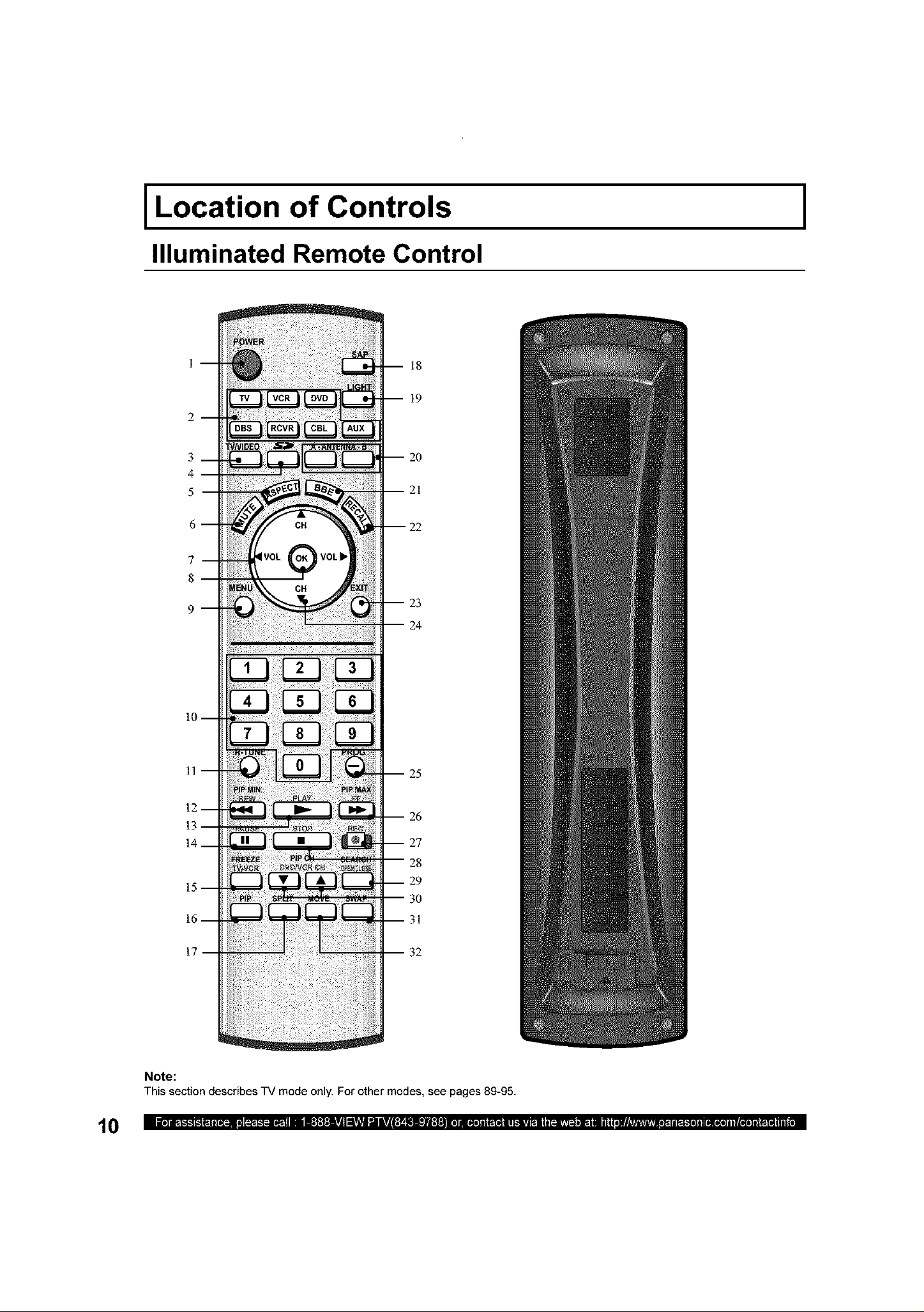
Location of Controls
Illuminated Remote Control
18
19
I
3
4
5
20
21
23
24
25
26
10
27
28
29
30
31
17
Note:
This section describes TV mode only. For other modes, see pages 89-95.
32
Location of Controls
POWER Press to turn ON and OFF.
rv Sets the remote to communicate with television
2 VCR, DVD, AUX,
CBL, RCVR, Sets the remote to communicate with other devices.
DBS
3 rVNIDEO Changes Input source.
4 SD Accesses the Photo Viewer feature (SD Card or PC Card).
5 _,SPECT Changes display aspect ratio.
6 MUTE Press to mute sound.
7 VOL • • Press to adjust TV sound and navigate in menus.
8 DK Press to choose menu and sub-menu entry.
9 MENU Press to display Main Menu or return one step backward in menus.
10 Number Press numeric keypad to select any channel or press to enter alphanumeric input in menus.
11 R-TUNE Press to switch to previously viewed channel, Photo Viewer or input modes.
PIP MIN While remote is in TV mode, press to decrease the PIP size.
12
REW While remote is in VCR or DVD mode, press to rewind.
13 PLAY While remote is in VCR or DVD mode, press to play.
14 PAUSE While remote is in VCR or DVD mode, press to pause.
FREEZE Still full video window.
15
rVNCR Press to switch to TV or VCR.
16 PIP Press to display or delete PIP screen.
17 ;PUT Press to display or delete Split screen.
18 ;AP In analog mode, press to access audio modes (Stereo, SAP or Mono). In digital mode, press
19 LIGHT Lights all buttons. The selected mode button (TV, VCR, etc.) flashes.
20 _,NTENNA A/B Press to switch to (A or B) RF antenna input.
21 BBE Press to turn BBE OFF or ON.
22 RECALL Press to display or delete Channel banner.
23 EXIT Press to exit menus.
24 CH • • Press to change channels and navigate in menus.
25 PROG Press after entering major channel numbers to enter minor (-) channel numbers.
PIP MAX While remote is in TV mode, press to increase the PIP size.
26
FF While remote is in VCR or DVD mode, press to fast forward.
27 REC While remote is in VCR mode, press to record.
28 STOP While remote is in VCR or DVD mode, press to stop.
;EARCH
29 to delete search screens.
)PEN/CLOSE While remote is in DVD mode, press to open or close DVD tray.
PIP CH • • While remote is in TV mode, press to change channels for PIP.
30
DVDNCR CH While remote is in VCR or DVD mode, press to change channels for DVD or VCR.
31 ;WAP Press to swap Main screen with PIP or Split screen.
32 MOVE While PIP screen is displayed, press to move to one of four corners.
to access next audio track.
While remote is in TV mode, press to scan available channels in search screens. Press again
11
Location of Controls
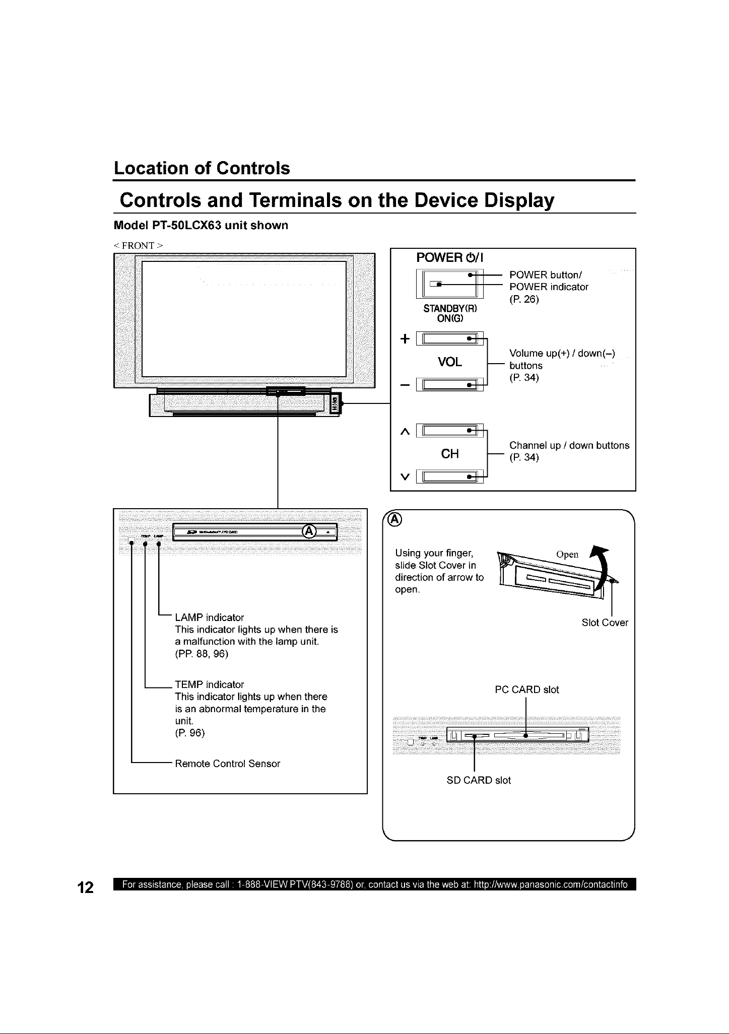
Controls and Terminals on the Device Display
Model PT-50LCX63 unit shown
FRONT >
POWER O/I
I
E3i
STANDBY(R)
ON(G)
-[
POWER button/
POWER indicator
(P. 26)
Volume up(+) / down(-)
buttons
(P. 34)
Channel up / down button,,
(P. 34)
_I_E i_i_ii_/_III_U _iJ ii_i_i:_i__ _ _
-- LAMP indicator
This indicator lights up when there is
a malfunction with the lamp unit.
(PE 88, 96)
__ TEMP indicator
This indicator lights up when there
isan abnormal temperature in the
unit.
(P. 96)
Remote Control Sensor
Using your finger,
slide Slot Cover in
direction of arrow to
open.
Slot Cover
PC CARD slot
SD CARD slot
12
k.
J
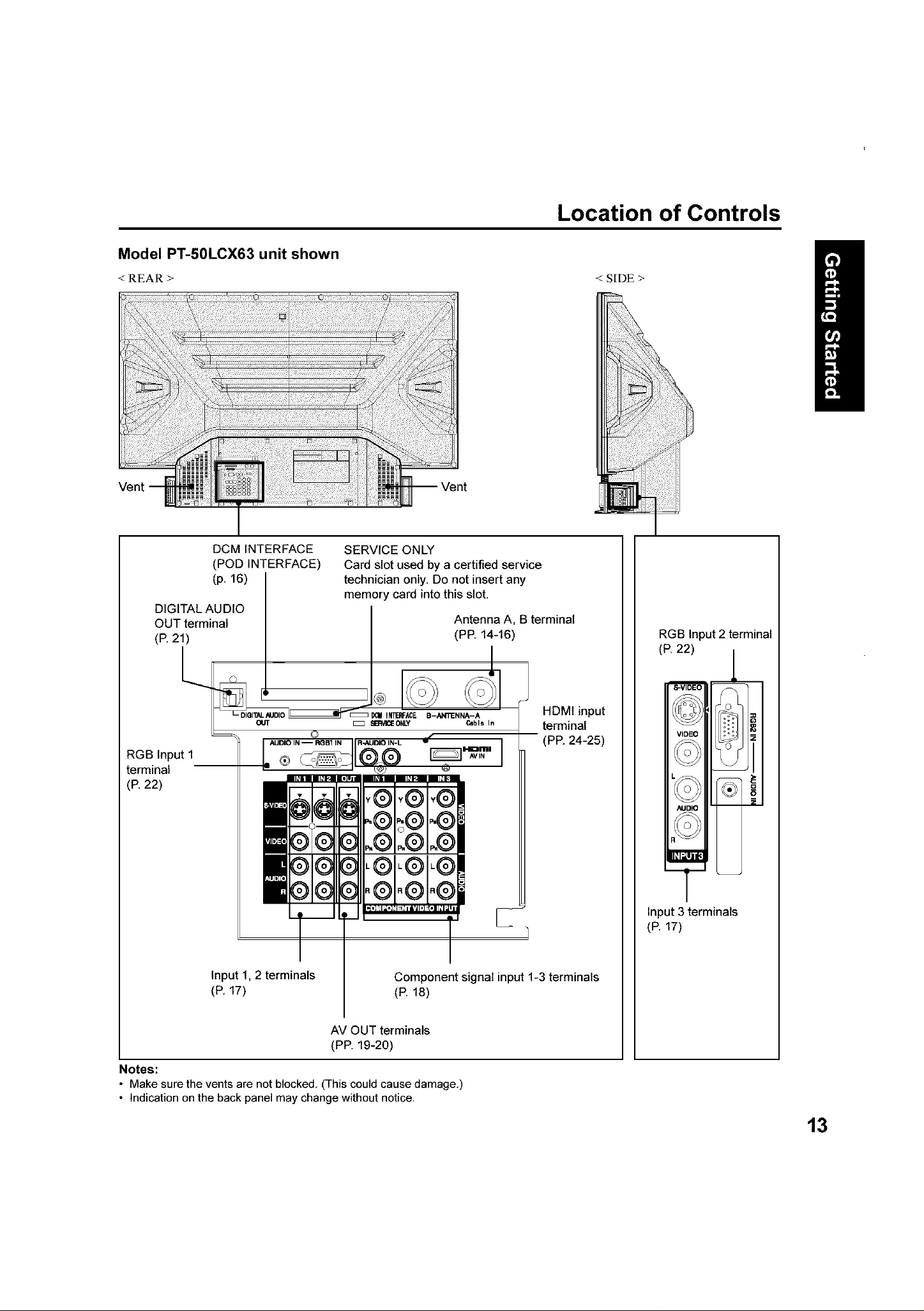
Location of Controls
Model PT-50LCX63 unit shown
< REAR > < SIDE >
DIGITAL AUDIO
OUT terminal
(P. 21)
RGB Input 1
terminal
(P. 22)
DCM INTERFACE
(POD INTERFACE)
(p. 16)
O_ DlalTALAIJDIO _ INTE_ACE B-AN_IENNA_A e
OUT _ _ SI_V_E ONLY
SERVICE ONLY
Card slot used by a certified service
technician only. Do not insert any
memory card into this slot.
Antenna A, B terminal
(PP. 14-16)
Y®
.® .®
I I I I_*]'l_*l _/l_'Jl,]
RGB Input 2 terminal
(R 22)
I
In
HDMI input
terminal
(PP. 24-25)
Input 3 terminals
(P. 17)
Input 1, 2 terminals
(P. 17)
AV OUT terminals
(PP. 19-20)
Notes:
• Make sure the vents are not blocked. (This could cause damage.)
• Indication on the back panel may change without notice.
Component signal input 1-3 terminals
(P. 18)
13
Installation
Notes on connections
Turn off the power suppl f for all components before making any connections,
If the cables necessary for connecting a component to the system are not included with the component or available as an
option, you may need to fashion a cable to suit the component concerned.
Read the instruction manual for each system component carefully before connecting it,
If there is a lot of jitter in the video signal input from the video source, the picture on the screen may flicker. In this case, it will
be necessary to connect a TBC (time base corrector).
When using "Nut type" RF coaxial cables tighten with fingers only. Overtightening may damage terminals.
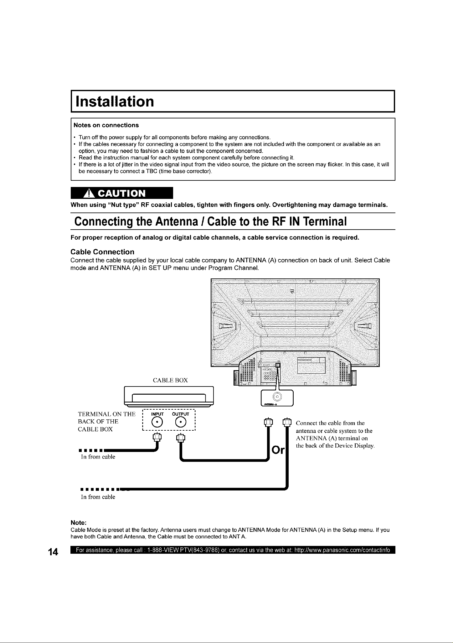
Connecting the Antenna / Cable to the RFINTerminal
For proper reception of analog or digital cable channels, a cable service connection is required.
Cable Connection
Connect the cable supplied by your local cable company to ANTENNA (A) connection on back of unit. Select Cable
mode and ANTENNA (A) in SET UP menu under Program Channel.
I
14
CABLEBOX
[, ,I
TERMINAL ON THE
BACK OF THE
CABLE BOX
mmmmm _ y r
In from cable
mmmmmmmm
In from cable
Note:
Cable Mode is preset at the factory. Antenna users must change to ANTENNA Mode for ANTEN NA (A) in the Setup menu, If you
have both Cable and Antenna, the Cable must be connected to ANT A,
INPUT OUTPUT
I,. ................ i
® ® !o
]
Connect the cable from the
antenna or cable system to the
ANTENNA (A) terminal on
the back of the Device Display.
Installation
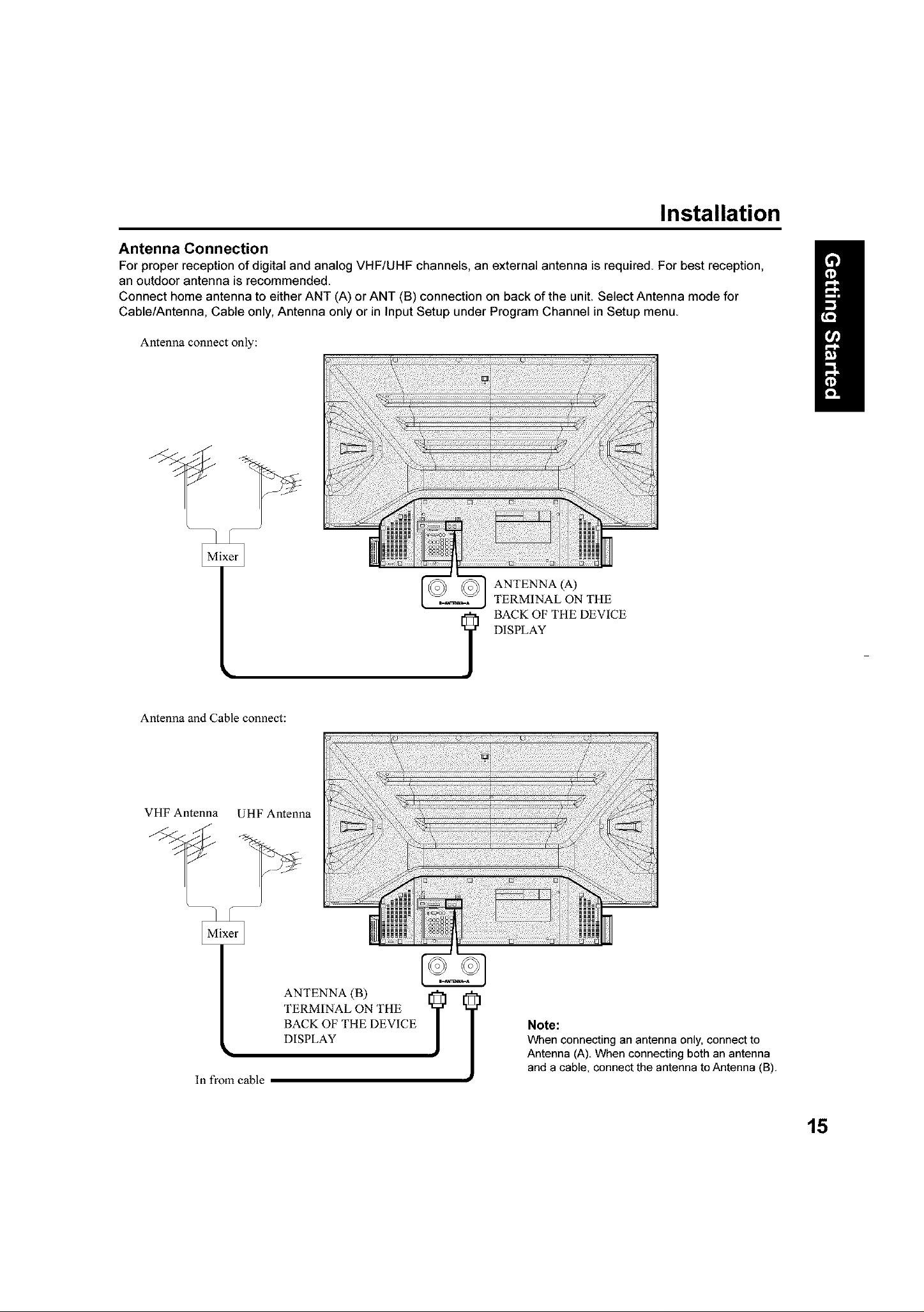
Antenna Connection
For proper reception of digital and analog VHF/UHF channels, an external antenna is required. For best reception,
an outdoor antenna is recommended.
Connect home antenna to either ANT (A) or ANT (B) connection on back of the unit. Select Antenna mode for
Cable/Antenna, Cable only, Antenna only or in Input Setup under Program Channel in Setup menu.
Antenna connect only:
Antenna and Cable connect:
VHF Antenna UHF Antenna
In from cable
ANTENNA (B)
TERMINAL ON THE
BACK OF THE DEVICE
DISPLAY
DISPLAY
I BACK OF THE DEVICE
Note:
When connecting an antenna only, connect to
Antenna (A). When connecting both an antenna
and a cable, connect the antenna to Antenna (B).
15
Installation
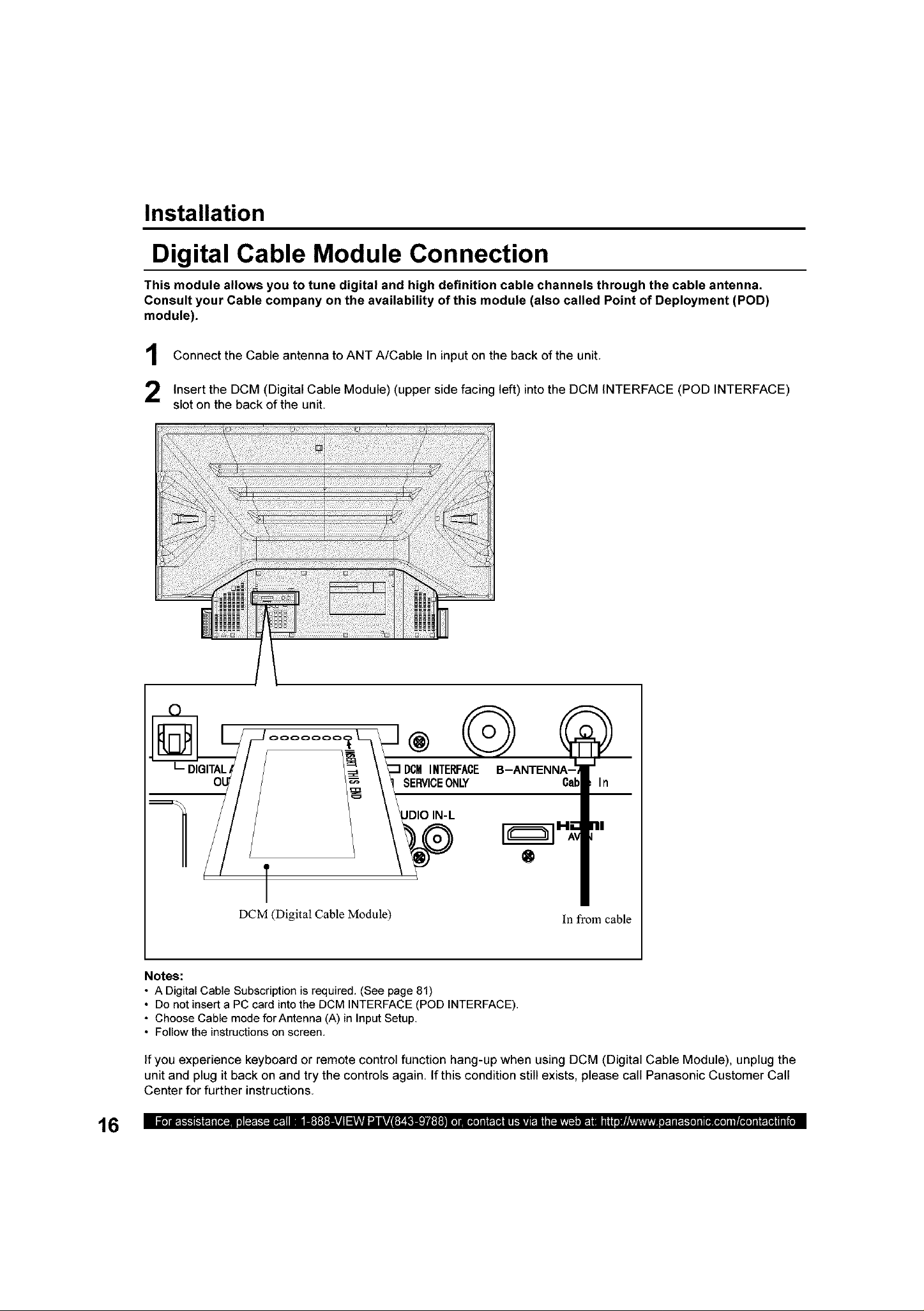
Digital Cable Module Connection
This module allows you to tune digital and high definition cable channels through the cable antenna.
Consult your Cable company on the availability of this module (also called Point of Deployment (POD)
module).
Connect the Cable antenna to ANT A/Cable In input on the back of the unit
Insert the DCM (Digital Cable Module) (upper side facing left) into the DCM INTERFACE (POD INTERFACE)
slot on the back of the unit.
16
L_DIGITAL
DCMINTERFACE
SERVICEONLY
JDIOIN-L
®
DCM (Digital Cable Module)
Notes:
• A Digital Cable Subscription is required, (See page 81)
• Do not insert a PC card into the DCM INTERFACE (POD INTERFACE),
• Choose Cable mode for Antenna (A) in Input Setup.
• Follow the instructions on screen,
if you experience keyboard or remote control function hang-up when using DCM (Digital Cable Module), unplug the
unit and plug it back on and try the controls again. If this condition still exists, please call Panasonic Customer Call
Center for further instructions.
ln from cable
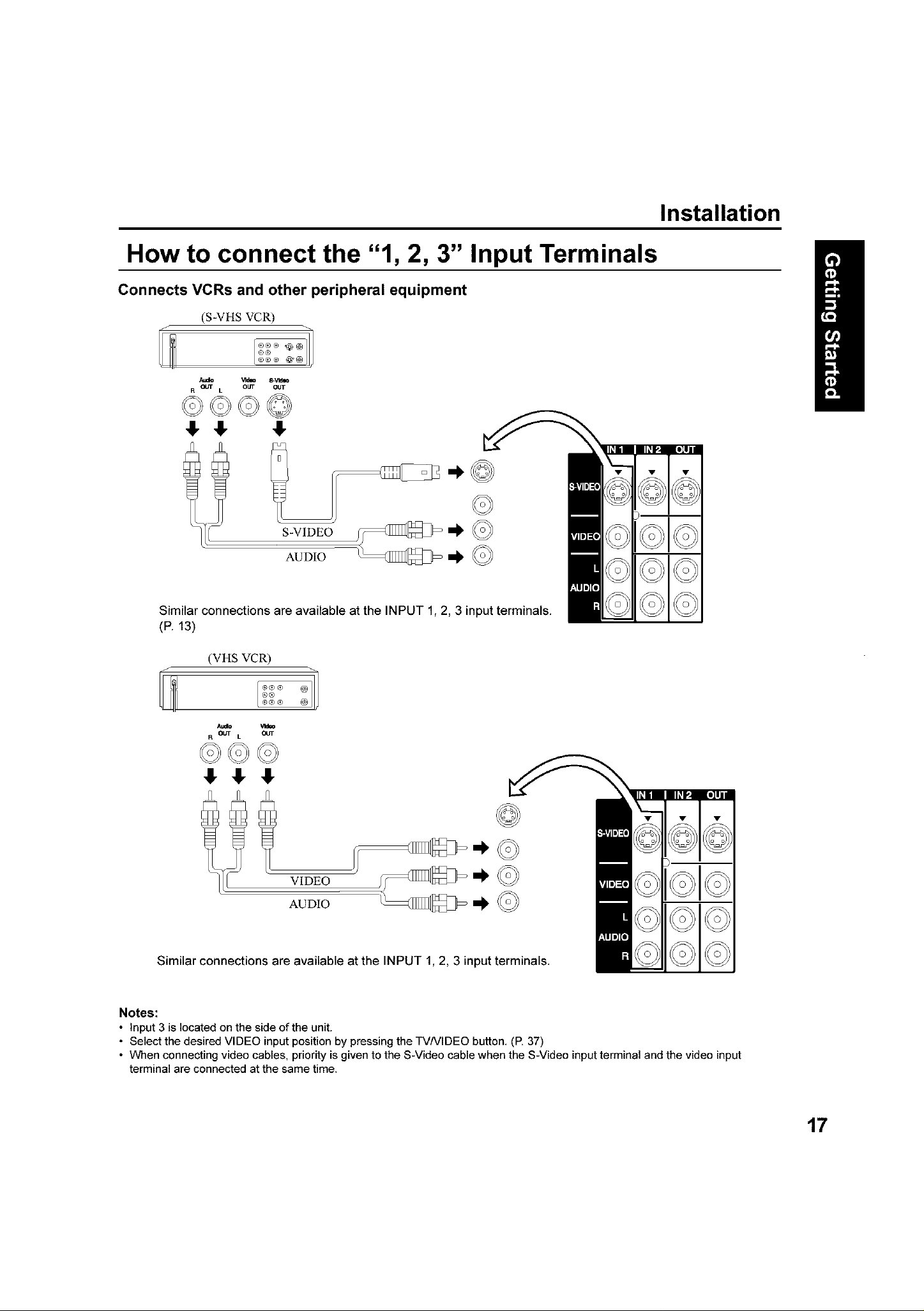
How to connect the "1, 2, 3" Input Terminals
Connects VCRs and other peripheral equipment
(S-VHS VCR)
Audio _ld_ _Vldlo
R OUT L OUT OUT
©©©©
41,41, 41,
S-VIDEO
AUDIO
Installation
Similar connections are available at the INPUT 1, 2, 3 input terminals.
(P. 13)
(VHS VCR)
Atdo Vldae
R OUT L OUT
©©©
V DEO
AUDIO
Similar connections are available at the INPUT 1, 2, 3 input terminals.
Notes:
• Input 3 is located on the side of the unit.
• Select the desired VIDEO input position by pressing the TVNIDEO button. (E 37)
• When connecting video cables, priority is given to the S-Video cable when the S-Video input terminal and the video input
terminal are connected at the same time.
17
Installation
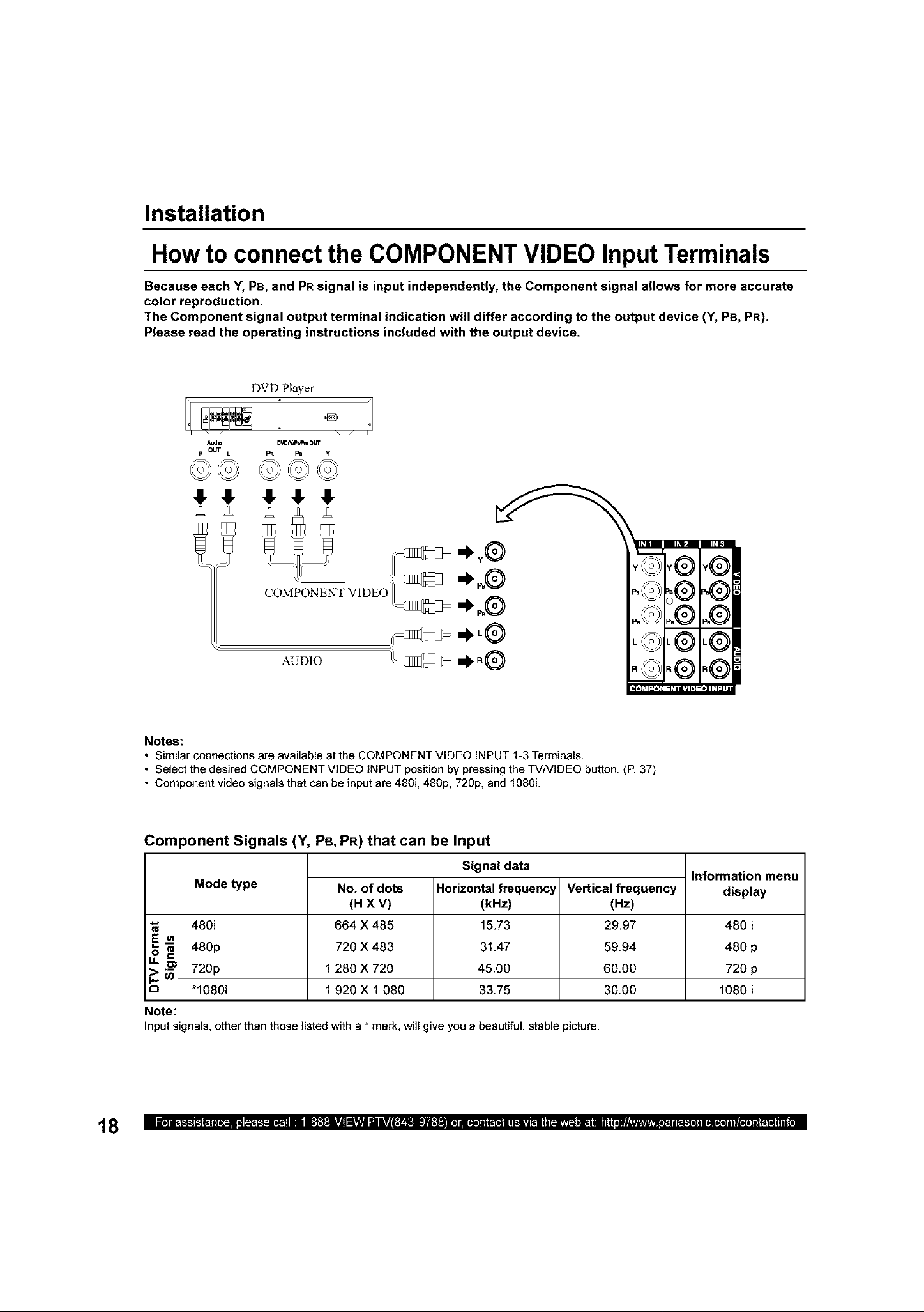
How to connect the COMPONENT VIDEO Input Terminals
Because each Y, PB, and PRsignal is input independently, the Component signal allows for more accurate
color reproduction.
The Component signal output terminal indication will differ according to the output device (Y, PB, PR).
Please read the operating instructions included with the output device.
DVD Player
Audio
R our L
©©
Notes:
• Similar connections are availaNe atthe COMPONENT VIDEO INPUT 1-3 Terminals.
• Select the desired COMPONENT VIDEO INPUT position by pressing the TVNIDEO button. (P. 37)
• Component video signals that can be input are 480i, 480p, 720p, and 1080L
_ Iy/_'I_I OUT
D_ _ Y
©©©
ENT VIDEO
AUDIO ii_ R@
18
Component Signals (Y, PB, PR) that can be Input
Signal data
Mode type
E=
o c
.I. _.)
r_ *lO8Oi 1080 i
Note:
Input signals, other than those listedwitha * mark, will give you a beautiful, stable picture.
480i 480 i
"_ 480p 480 p
_ 720p 720 p
No. of dots
(H X V)
554 X 485
720 X 483
1 280 X 720
1 920 X 1 080
Horizontal frequency
(kHz)
15.73
3147
4500
33.75
Vertical frequency
(Hz)
2997
5994
6000
30.00
Information menu
display
Installation
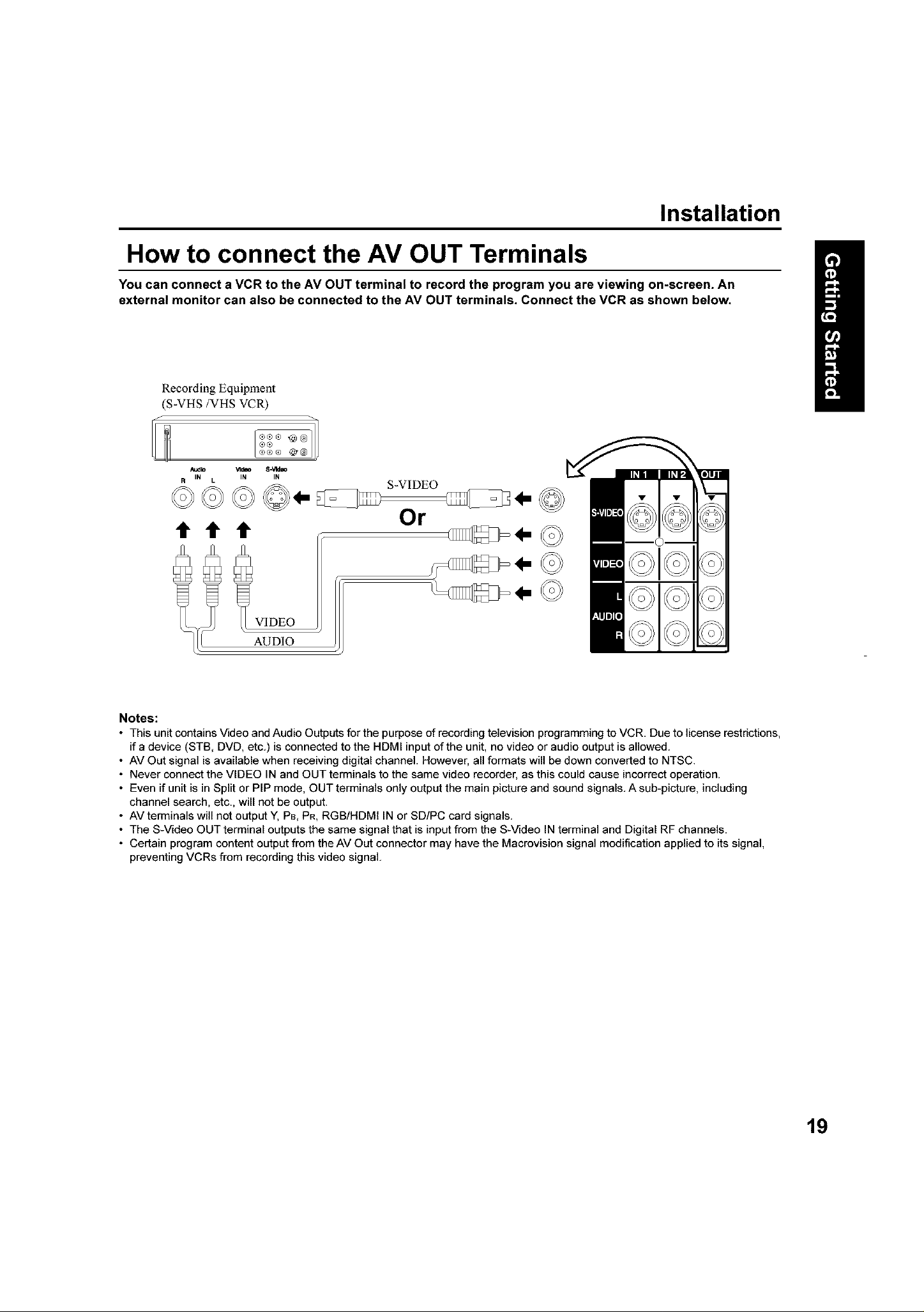
How to connect the AV OUT Terminals
You can connect a VCR to the AV OUT terminal to record the program you are viewing on-screen. An
external monitor can also be connected to the AV OUT terminals. Connect the VCR as shown below.
Recording Equipment
(S-VHS/VHS VCR)
Audlo _I_o S.V1deo
IN IN IN
R c
ttt
S-VIDEO
Or
v
//,_&\
I/® )/
,.©
Notes:
• This unit contains Video and Audio Outputs for the purpose of recordingtelevision programming to VCR Due to license restrictions,
if a device (STB, DVD, etc) is connected to the HDMI input of the unit, no video or audio output is allowed
• AV Out signal is available when receiving digital channel However, all formats will be down converted to NTSC
• Never connect the VIDEO IN and OUT terminals to the same video recorder, as this could cause incorrect operation
• Even if unit is in Split or PIP mode, OUT terminals only output the main picture and sound signals A sub-picture, including
channel search, etc, will not be output
• AV terminals will not output Y, PB,PR, RGB/HDMI IN or SD/PC card signals
• The S-Video OUT terminal outputs the same signal that is input from the S-Video IN terminal and Digital RF channels
• Certain program content output from the AV Out connector may have the Macrovision signal modification applied to its signal,
preventing VCRs from recording this video signal
I/o ))
I( o ))
19
Installation
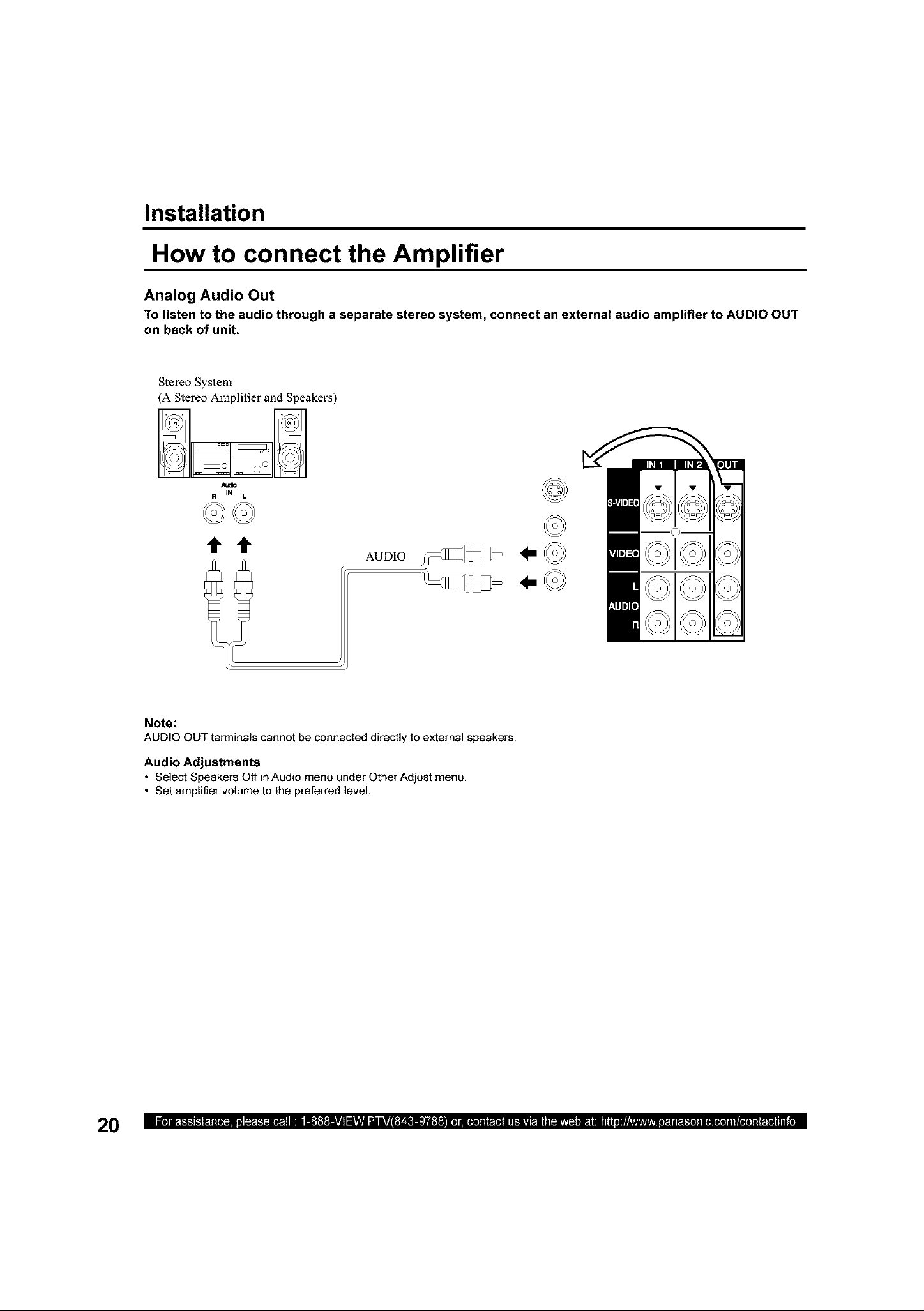
How to connect the Amplifier
Analog Audio Out
To listen to the audio through a separate stereo system, connect an external audio amplifier to AUDIO OUT
on back of unit,
Stereo System
(A Stereo Amplifier and Speakers)
Audb
IN L
2t
Note:
AUDIO OUT terminals cannot be connected directly to external speakers.
Audio Adjustments
• Select Speakers Off in Audio menu under Other Adjust menu.
• Set amplifier volume to the preferred level,
AUDIO _
1-
v
I()1
IC/ I
i
2O
Installation
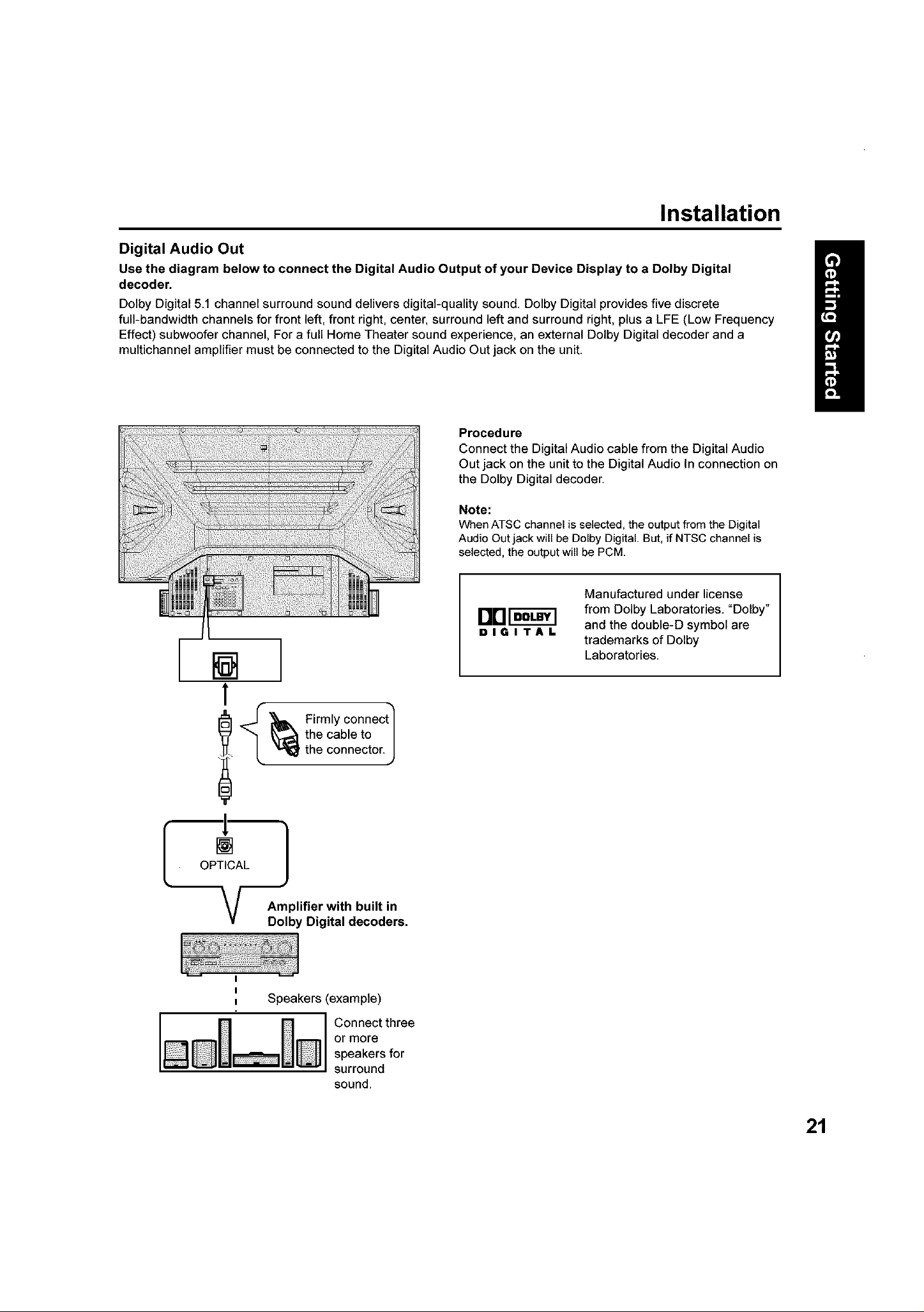
Digital Audio Out
Use the diagram below to connect the Digital Audio Output of your Device Display to a Dolby Digital
decoder.
Dolby Digital 51 channel surround sound delivers digital-quality sound. Dolby Digital provides five discrete
full-bandwidth channels for front left, front right, center, surround left and surround right, plus a LFE (Low Frequency
Effect) subwoofer channel, For a full Home Theater sound experience, an external Dolby Digital decoder and a
multichannel amplifier must be connected to the Digital Audio Out jack on the unit.
Procedure
Connect the Digital Audio cable from the Digital Audio
Out jack on the unit to the Digital Audio In connection on
the Dolby Digital decoder.
Note:
When ATSC channel is selected, the output from the Digital
Audio Out jack will be Dolby Digital. But, if NTSC channel is
selected, the output will be PCM
[]
1
_J
the cable to
"_ Firmly connect
the connector.
Amplifier with built in
Dolby Digital decoders.
J
I]13r r -]
DIGITAL
Manufactured under license
from Dolby Laboratories. "Dolby"
and the double-D symbol are
trademarks of Dolby
Laboratories.
Speakers (example)
Connect three
or more
speakers for
surround
sound.
21
Installation
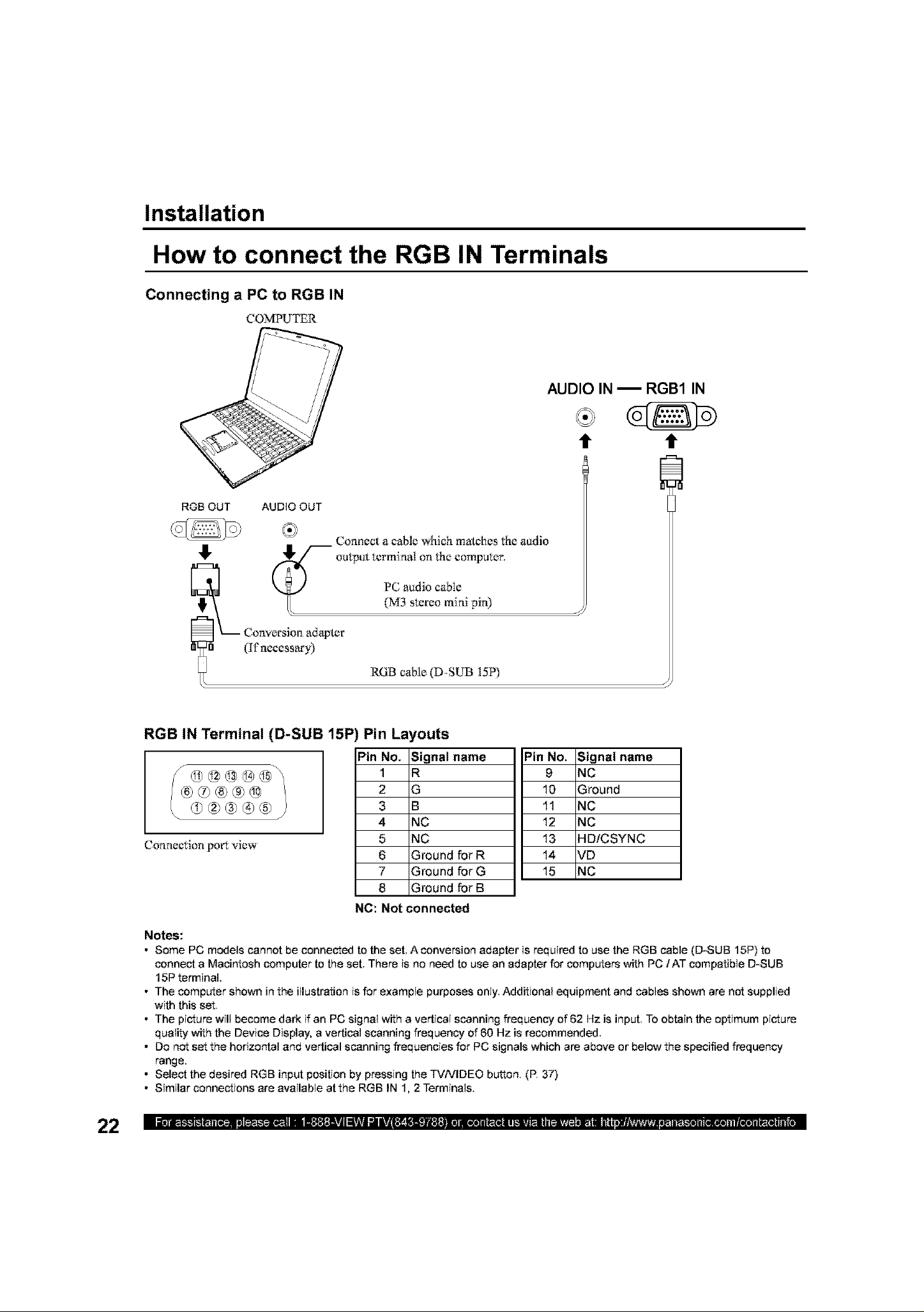
How to connect the RGB IN Terminals
Connecting a PC to RGB IN
COMPUTER
AUDIO IN _ RGB1 IN
RGB OUT AUDIO OUT
Connect a cable which matches the audio
,!,
(_-"-o_ltput terml aat on the comvater.
P(2 audio cable
(M3 stereo miai pia)
t" t"
C_._ Conversion adapter
(II'necessary)
RGB cane (D-SUB 15P)
RGB IN Terminal (D-SUB 15P
Connection port view
Notes:
• Some PC models cannot be connected to the set. A conversion adapter is required to use the RGB cable (D-SUB 15P) to
connect a Macintosh computer to the set. There is no need to use an adapter for computers with PC/AT compatible D-SUB
15P terminal.
• The computer shown in the illustration is for example purposes only. Additional equipment and cables shown are not supplied
with this set
• The picture will become dark if an PC signal with a vertical scanning frequency of 82 Hz is input. To obtain the optimum picture
quality with the Device Display, a vertical scanning frequency of 80 Hz is recommended.
• Do not set the horizontal and vertical scanning frequencies for PC signals which are above or below the specified frequency
range.
• Select the desired RGB input position by pressing the TVNIDEO button. (P. 37)
• Similar connections are available atthe RGB IN 1, 2 Terminals.
Pin Layouts
Pin No.
NC: Not connected
1
2
3
4
5
6
7
8
Signal name
R
G
B
NC
NC
Ground for R
Ground for G
Ground for B
=in No. Signal name
9 NC
10 Ground
1t NC
12 NC
13 HDiCSYNC
14 VD
15 NC
Installation
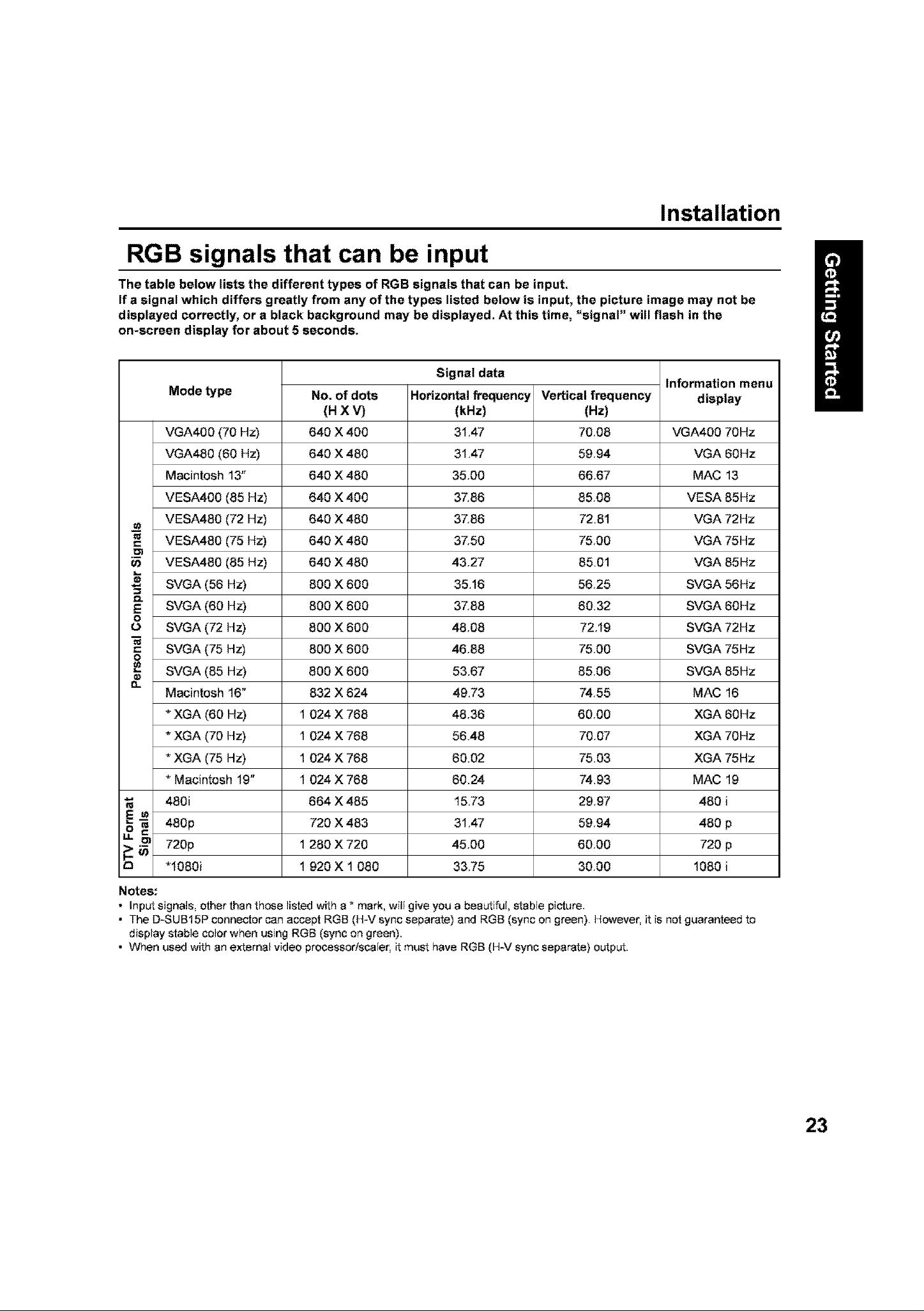
RGB signals that can be input
The table below lists the different types of RGB signals that can be input.
If a signal which differs greatly from any of the types listed below is input, the picture image may not be
displayed correctly, or a black background may be displayed. At this time, "signal" will flash in the
on-screen display for about 5 seconds.
Signal data
Mode type
VGA400 (70 Hz) VGA400 70Hz
VGA480 (60 Hz) VGA 60Hz
Macintosh 13" MAC 13
VESA400 (85 Hz) VESA 85Hz
VESA480 (72 Hz) VGA 72Hz
=_ VESA480 (75 Hz) VGA 75Hz
t33
VESA480 (85 Hz) VGA 85Hz
SVGA (56 Hz) SVGA 56Hz
_" SVGA (60 Hz) SVGA 80Hz
o
O SVGA (72 Hz) SVGA 72Hz
SVGA (75 Hz) SVGA 75Hz
SVGA (85 Hz) SVGA 85Hz
0.
Macintosh 16" MAC 16
* XGA (60 Hz) 1 XGA 60Hz
* XGA (70 Hz) 1 XGA 70Hz
* XGA (75 Hz) 1 XGA 75Hz
* Macintosh 19" 1 MAC 19
"_ 480i 480 i
,o
> _ 720p 1 720 p
r_ "1080i 1 1080 i
480p 480 p
No. of dots
(HXV)
640 X 400
640 X 480
640 X 480
640 X 400
640 X 480
640 X 480
640 X 480
800 X 600
800 X 800
800 X 800
800 X 800
800 X 800
832 X 824
024 X 768
024 X 768
024 X 768
024 X 768
864 X 485
720 X 483
280 X 720
920 X 1 080
Horizontal frequency
(kHz)
31,47
31,47
35,00
37,86
37,86
37,50
43,27
35,16
37,88
48.08
46,88
53,67
49,73
48,36
56,48
60,02
60,24
15,73
31,47
45,00
33,75
Vertical frequency
(Hz}
70.08
59,94
66,67
85.08
72,8t
75.00
85,0t
56,25
60,32
72,19
75,00
85.06
74,55
60,00
70,07
75,03
74,93
29,97
59,94
60,00
30,00
Information menu
display
Notes:
• Input signals, other than these listed with a * mark, will give you a beautiful, stable picture.
• The D-SUB15P connector can accept RGB (H-v' sync separate) and RGB (sync on green) However, it is not guaranteed to
display stable color when using RGB (sync on green).
• When used with an external video processor/scaler, it must have RGB (H-v' sync separate) output.
23
Installation
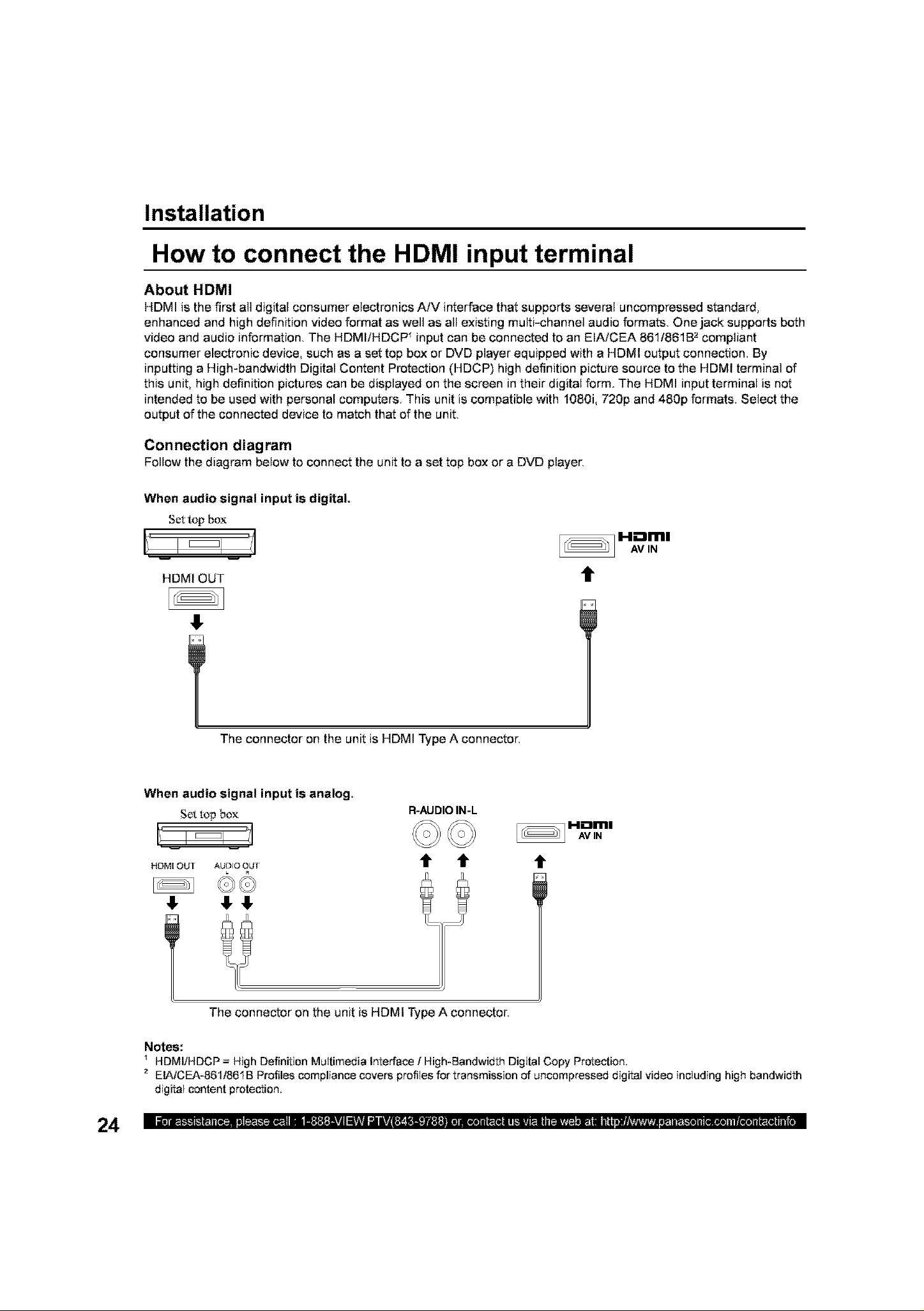
How to connect the HDMI input terminal
About HDMI
HDMI is the first all digital consumer electronics AiV interface that supports several uncompressed standard,
enhanced and high definition video format as well as all existing multi-channel audio formats. One jack supports both
video and audio information. The HDMIiHDCP _input can be connected to an EIAiCEA 86t/861B _compliant
consumer electronic device, such as a set top box or DVD player equipped with a HDMI output connection. By
inputting a High-bandwidth Digital Content Protection (HDCP) high definition picture source to the HDMI terminal of
this unit, high definition pictures can be displayed on the screen in their digital form. The HDMI input terminal is not
intended to be used with personal computers. This unit is compatible with 1080i, 720p and 480p formats. Select the
output of the connected device to match that of the unit.
Connection diagram
Follow the diagram below to connect the unit to a set top box or a DVD player,
When audio signal input is digital.
Set{op box
i '1
HDMI OUT
The connector on the unit is HDMI Type A connector.
When audio signal input is analog,
Sc_.top box
HDMI OUT AUDIO OUT
R-AUDIO IN-L
t t t
[_ H'im!
AVN
t
The connector on the unit is HDMI Type A connector.
Notes:
HDMIiHDCP = High Definition Multimedia Interface / High-Bandwidth Digital Copy Protection.
2 EIAiCEA-861i861B Profiles compliance covers profiles for transmission of uncompressed digital video including high bandwidth
digital content protection.
Installation
Procedure
Connect the HDMI output from the set top box or a DVD player to the HDMI input on the back of the unit.
1
• If you cannot display the picture because your Digital Set Top Box does not have e Digital Out terminal
setting, use the Component Video Input (or the S-Video Input or Video Input). In this case, the picture will be
displayed as an analog signal.
Press TViVIDEO on the Remote Control to select HDMI input.
By inputting a High-bandwidth Digital Content Protection high-definition picture source to the HDMI IN terminal of
this Device Display, high-definition pictures can be displayed on the screen in their digital form. (This terminal is for
use in the future when High-bandwidth Digital Content Protection DVD players and D-VHS are put on the market.)
Notes:
• Select the HDMI input position by pressing the TVNIDEO button. (P. 37)
• The HDMI IN terminal can only be used with 1080i, 720p and 480p picture signals.
• If there is no audio, check if the source equipment has PCM output. If not, please use analog connections.
• Be sure HDMI issecurely connected. If not, picture noise andtor incorrect picture display may result.
• With HDMI connection, depending on the signal, the picture may be displayed with unnatural colors (as if red and blue are
reversed). See UV Timing of Page 53.
Compatible formats
Video Signal:
The Device display is compatible with following formats. Please set the connecting device to following format.
Display mode
1OSOi
720p
480p
Audio signal (PCM)
When digital audio is included in the HDMI connection, the compatible sampling frequencies are 48 kHzi44.1 kHzi32
kHz. (See page 55)
No. ofdots
1920 x 1080i
1280 x 720p
720 x 480p
840 x 480p
Vertical scanning frequency (Hz)
59.94 / 60
59.94 / 60
59.94 / 60
59.94 / 60
25
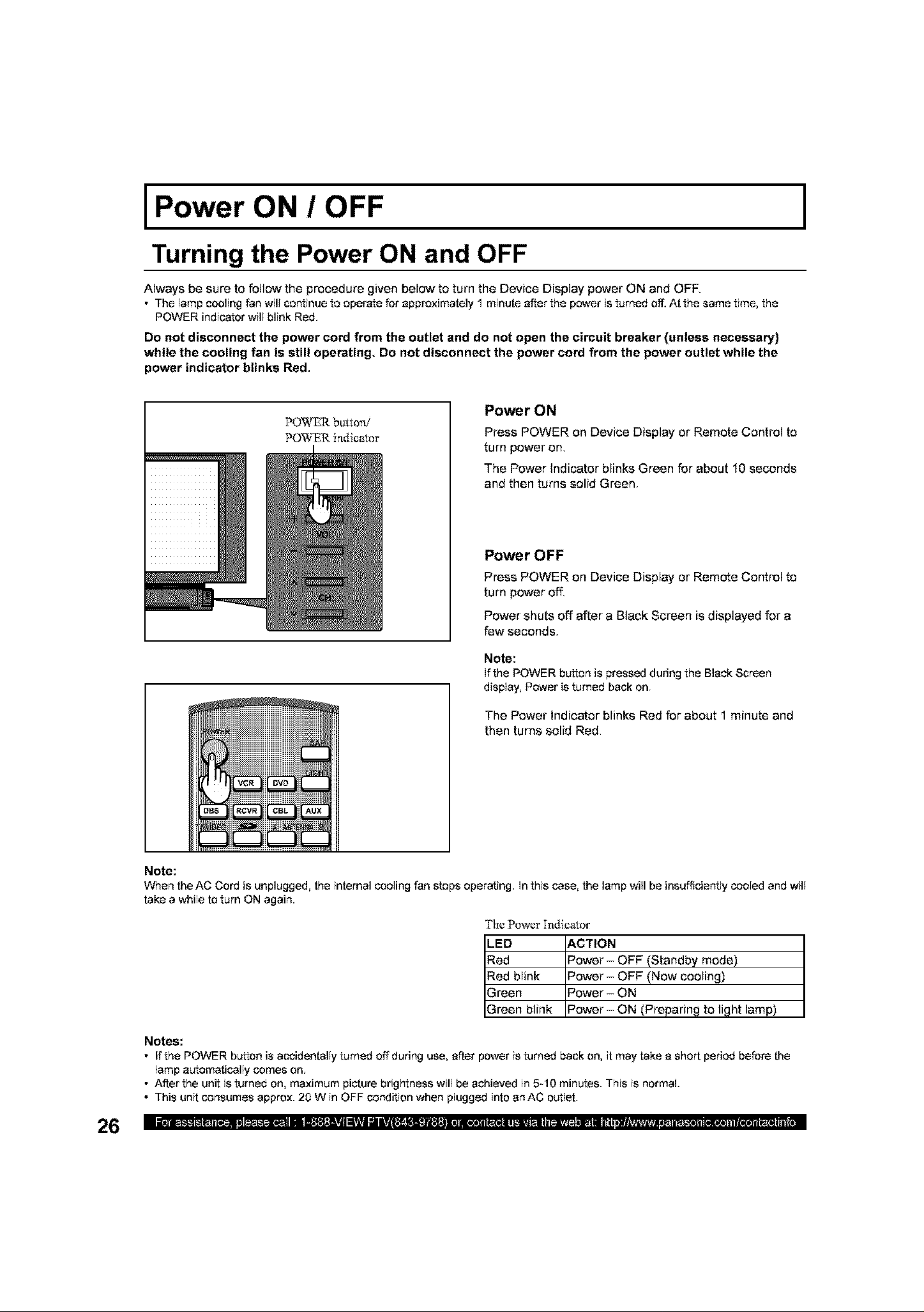
Power ON / OFF
Turning the Power ON and OFF
Always be sure to follow the procedure given below to turn the Device Display power ON and OFE
• The lamp cooling fan will continue to operate for approximately 1 minute after the power is turned off.At the same time, the
POWER indicator will blink Red.
Do not disconnect the power cord from the outlet and do not open the circuit breaker (unless necessary)
while the cooling fan is still operating. Do not disconnect the power cord from the power outlet while the
power indicator blinks Red.
I
POWER bt_tton/
POWER indicator
Power ON
Press POWER on Device Display or Remote Control to
turn power on,
The Power Indicator blinks Green for about 10 seconds
and then turns solid Green.
Power OFF
Press POWER on Device Display or Remote Control to
turn power ofl_
Power shuts off after a Black Screen is displayed for a
few seconds.
Note:
Ifthe POWER button is pressed during the Black Screen
display, Power is turned back on.
The Power Indicator blinks Red for about 1 minute and
then turns solid Red,
Note:
When the AC Cord is unplugged, the internal cooling fan stops operating. In this case, the lamp will be insufficiently cooled and will
take a while to turn ON again.
The Power llndieator
LED ACTION
Red Power - OFF (Standby mode)
Red blink Power - OFF (Now cooling)
Green Power - ON
Green blink Power- ON (Preparing to light lamp)
Notes:
• If the POWER button is accidentally turned off during use, after power is turned back on, it may take a short period before the
lamp automatically comes on.
• After the unit isturned on, maximum picture brightness will be achieved in 5-10 minutes. This is normal.
• This unit consumes approx. 20 W in OFF condition when plugged into an AC outlet.
Power ON / OFF
First Time Setup
For your convenience, First Time Set up menu will be displayed on screen when the set is turned on for the
first time. If needed, follow the menus and procedures displayed on-screen for setting up the features.
Input Setup
To select the configuration of RF input depending on the signal source.
Note:
No video will bedisplayed inthis setup mode.
Procedure
Press VOL I_ to select Cable only, Cable/Antenna, or Antenna only.
Press OK to underline your selection.
When the next screen is displayed, press OK to start the Auto Scan. All
available channels with a signal will be programmed into memory.
Auto Scan
This feature allows you to selectively auto scan channels. You can Scan
All, Analog only channels, or Analog & Digital channels.
Procedure
Press OK to start Auto Scan.
After Auto Scan is completed the unit tunes to the first channel found
during auto scan.
Notes:
• If DCM (Digital Cable Module) is present during the First Time Setup end Antenna (A)
is set to cable, Antenna (A) wiJl net be scanned due to the DCM providing the channel
map.
• If setup is incomplete, check connection of Antenna/Cable to the RF IN Terminal, then
tryAuto Scan again. (PP. 30-31)
Notes:
• Auto scan must be done when you select the input signal for the first time or whenever you change the antenna configuration.
• Depending on conditions, Auto scan may take a while.
27
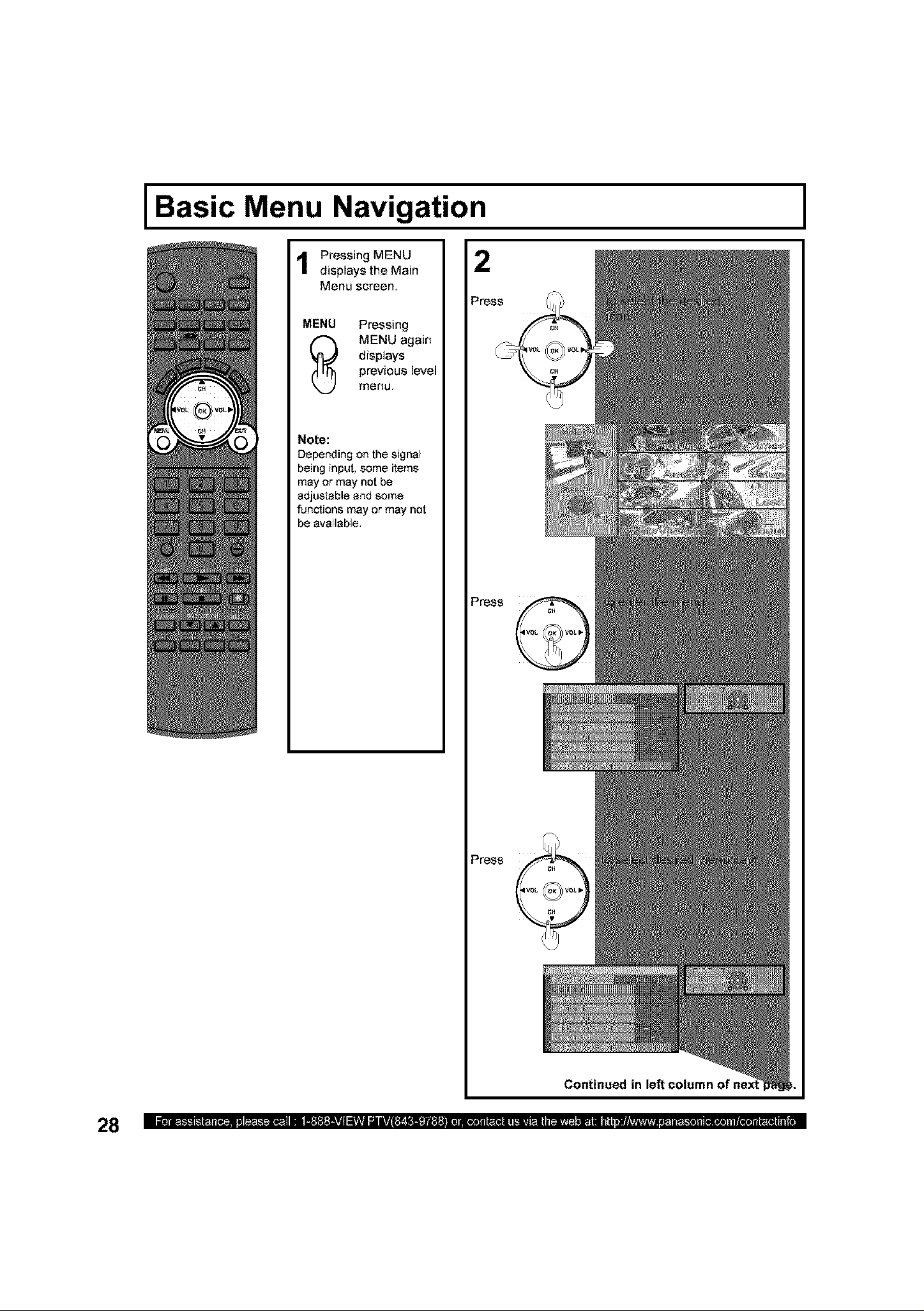
Basic Menu Navigation
Pressing MENU
displays the Main
Menu screen.
MENU Pressing
displays
_ MENU again
Note:
Depending Onthe signal
being input, some items
may or may not be
adjustable end some
functions may or may not
be available.
previous level
menu,
I
Press
Press
Press
Continued in left column
Continued from page
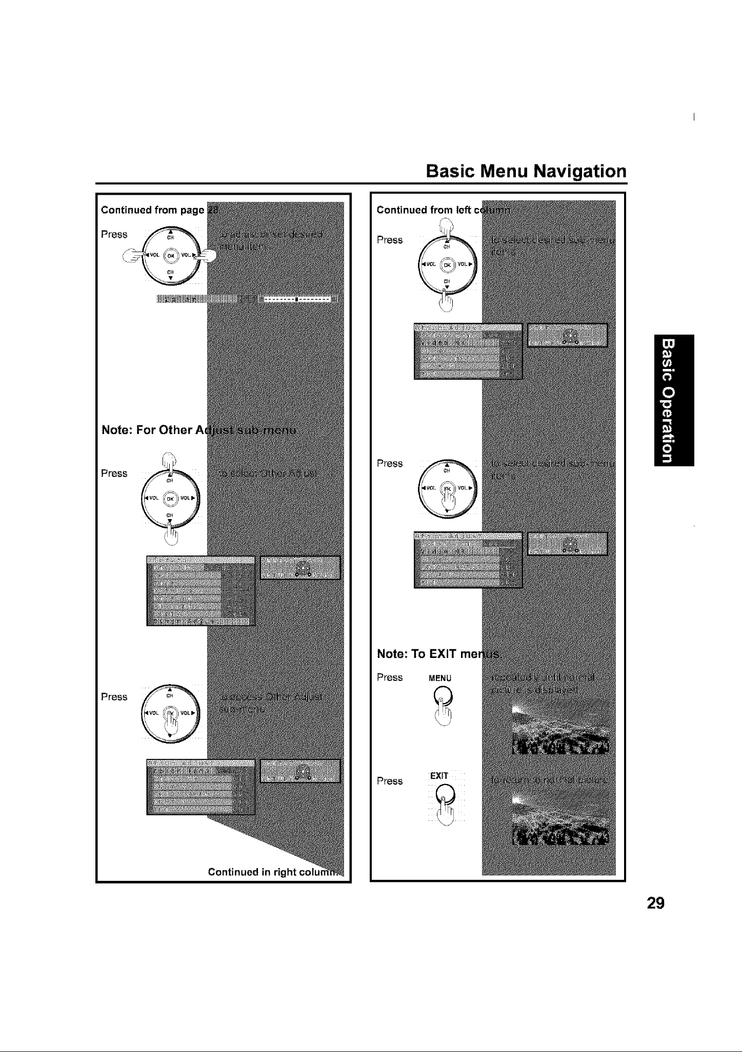
Basic Menu Navigation
Press
Note: For Other At
Press
Press
Press
Press
Continued in right colu_
Note: To EXIT mer
Press MENU
Press
EXIT
29
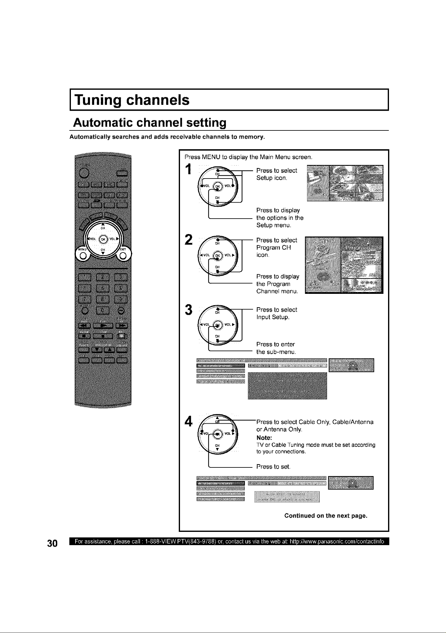
Tuni channels
Automatic channel setting
Automatically searches and adds receivable channels to memory.
Press MENU to display the Main Menu screen,
Setup icon,
1 Press to select
Press to display
the options in the
Setup menu,
Press to select
Program CH
icon,
Press to display
the Program
Channel menu,
I
Input Setup,
V0L VOL •
_ Press to select
Press to enter
the sub-menu,
4 Press to select Cable Only, Cable/Antenna
or Antenna Only,
Note:
TV or Cable Tuning mode must beset according
to your connections.
Press to set,
xx
Continued on the next page.
 Loading...