

Panasonic PT-51HX42C, PT-61HX42C Operating Instructions Manual

®
HDTV Projection Monitor
Operating Instructions
TQB2AA0443 20503
PRINTED IN USA
PT-51HX42C PT-61HX42C
WARNING
RISK OF ELECTRIC SHOCK
DO NOT OPEN
WA RNIN G: To reduce the risk of electric shock do not remove cover or back.
No user-serviceable par ts i nside. Refer se rvicing t o qual ifie d servi ce per sonnel.
WARNING: TO REDUCE THE RISK OF FIRE OR ELECTRIC SHOCK, DO
FCC CAUTION:
ENVIRONMENTAL NOTICE:
The lightning f lash with arrow
head within a triangle is
intended to tell the user that
parts inside the product are a
risk of electric shock to
persons.
The exclamation p oint within a
triangle is intended to tell the
user that important operating
and servicing instructions are
in the papers with the
appliance.
NOT EXPOSE THIS APPARATUS TO RAIN OR MOISTURE.
ANY CHANGES OR MODIFICATIONS TO THIS PTV
RECEIVER NOT EXPRESSLY APPROVED BY
MATSUSHITA ELECTRIC CORPORATION OF AMERICA
COULD CAUSE HARMFUL INTERFERENCE, WHICH
WOULD VOID THE USER’S AUTHORITY TO OPERATE
THIS EQUIPMENT.
THIS PRODUCT UTILIZES CATHODE RAY TUBES (CRT) AND OTHER
COMPONENTS THAT CONTAIN LEAD. DISPOSAL OF THESE MATERIALS
MAY BE REGULATED IN YOUR COMMUNITY DUE TO ENVIRONMENTAL
CONSIDERATIONS. FOR DISPOSAL OR RECYCLING INFORMATION
PLEASE CONTACT YOUR LOCAL AUTHORITIES, OR THE ELECTRONICS
INDUSTRIES ALLIANCE: <HTTP://WWW.EIAE.ORG.>
This product incorporates U.S. Patent 6,266,098 B1; Issue date: July 24, 2001; assigned
to Matsushita Electric Corporation of America; other U.S. and foreign patents pending.
Manufactured under license from BBE Sound, Inc.
Licensed by BBE Sound, Inc. under USP4638258 and 4482866.
High Definition Sound
Read these instructions completely before operating television.
Contents are subject to change without notice or obligation.
Copyright 2002 by Matsushita Electric Corporation of America. All rights reserved.
Unauthorized copying and distribution is a violation of law.
BBE and BBE symbol are registered trademarks of BBE Sound, Inc.
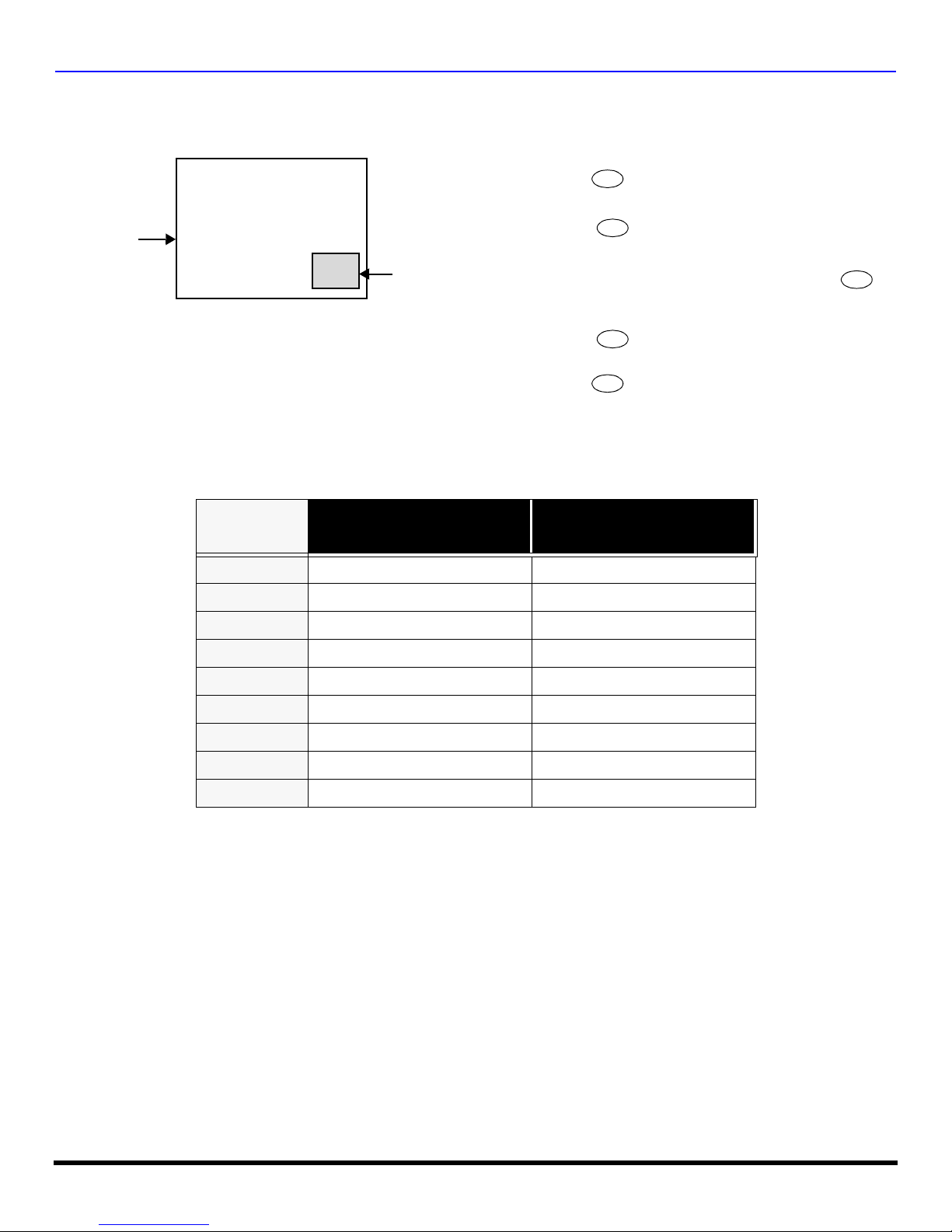
INFORMATION REGARDING CONVERGENCE
In the projection television, the image is formed by projecting 3 different color images (red, green and blue) onto the
projection screen . Convergence refers to the alignment of red, green and blue images on the projection screen.
When these images a re properly aligned (converged), you see a sharp and vibrant col or image. Sometimes, the three
images may require alignment. This is due to the effect of earth’s magnetic field on the projection tubes. Normally,
adjustment is not necess ary after the initi al ali gnment a t the cen ter of the s creen. It i s possi ble to cor rect the c olor fr ingi ng
on other areas of the screen by using the but tons on the remo te control and by followin g the on-scr een instruc tions in th e
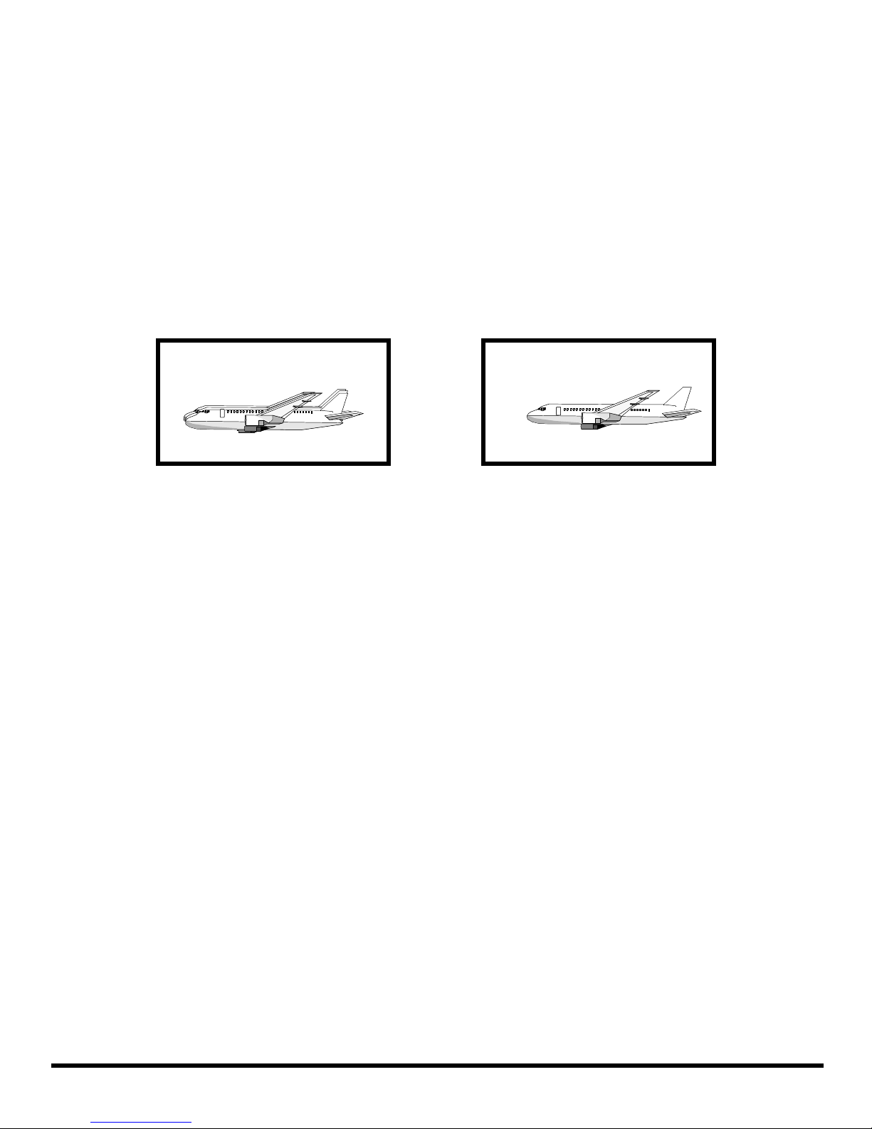
set-up menu. Please converge the images before using the television for the first time. The following diagram shows
examples of a mis aligned imag e and a properl y aligned im age. Please refer to pages 28-29 for detailed procedure on
how to adjust convergence.
Misconverged image
Properly aligned imag e
1 l

T
ABLE OF CONTENTS
Table of Contents
Congratulations.........................................................3
Customer Record ......................................................................3
Care and Cleaning.................. ....... ...... ....... ...... ...... ....... ...... ......3
Specifications ................................ ...... ......................................3
Installation..................................................................4
Television Location....................................................................4
Optional Cable Connections......................................................4
AC Power Supply Cord..............................................................4
Cable / Antenna Connection......................................................4
Feature Chart .............................................................5
Auto Set Up Menu......................................................6
Optional Equipment Connections ...........................7
VCR .........................................................................................7
Cable Box............................................................... ....... ...... ......8
VCR and Cable Box ..................................................................8
Amplifier (TO AUDIO AMP).......................................................9
Front Control Panel .................................................................10
Program Out (PROG OUT) .....................................................11
Digital TV - Set-Top Box (DTV-STB) or DVD Players.............11
PIP and Split Operation........................................... 12
Special Remote Buttons..........................................................14
Remote Control Operation......................................15
Mode Operational Key Chart ..................................................16
Programming the Remote .......................................................18
Component Codes.................. ....... ...................................... ....19
Roller Guide Menu™ Navigation............................23
Roller Guide Icons............................................ ..... ..25
Roller Guide Icon Menus.........................................................25
Rollerguide Icon Menu Operation.......................... 26
Set Up......................................................................................26
Timer .......................................................................................30
Picture .....................................................................................31
Selectable 16:9 Mode Feature Chart.......................................33
Channels .................................................................................33
Audio .......................................................................................35
Lock.........................................................................................36
V-Chip Menu Operation...........................................37
Troubleshooting Chart............................................43
Limited Warranty..................................................... 44
Index .........................................................................45
2 l

C
ONGRATULATIONS
Congratulations
Your new Proj ectio n Television (PTV) features state-of-the-art techno logy for hig h qual ity p icture and s ound with comp let e
audio/video connecti ons for y our home theater system. Your PTV is designed to give you many years of e njo ym ent . It was
thoroughly tested and tuned at the factory for best performance.
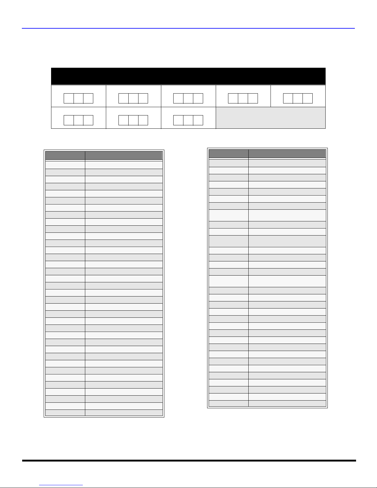
Customer Record
The model and serial number of this product are located on the back of the PTV. You should note the model and serial number in
the space provided and retain as a permanent record of your purchase. This will aid in identification in the event of theft or loss.
Model
Number
Serial
Number
Care and Cleaning
Projection Screen (T urn TV Off)
The projection screen is a high precision lens system which has a protective screen. The protective screen is fully
washable with the following precautions:
r Use a mild soap solution or window cleaner and a clean cloth.
• DO NOT USE ABRASIVE CLEANERS.
• Do not use laundry detergent or automatic dishwasher soap.
• Do not use alcohol, ammonia, or petroleum based products.
r Avoid excessive moisture and wipe dry.
• Prevent solution from running into the receiver below.
r Avoid bumping or scraping the screen.
Note: Do not spray any type of cleaning fluid directly on the screen.
Cabinet and Remote Control
r For cabinets and remote contro l, use a soft cloth dampened with water or a m ild detergent solut ion. Avoid excessive
moisture and wipe dry.
r Do not use benzene, thinner or other petroleum based products.
Specifications
Power Source
Component Input (Y / PB / PR)
PT-51HX42C (4.2A)
PT-61HX52C (4.2A)
Channel Capability - 181 VHF-12; UHF-56; Cable-113
Video Input Jacks 1Vp-p, 75 Ohm, Phono Jack Type
Audio Input Jacks 500mV RMS 47K Ohm
Video Output Jack 1Vp-p, 75 Ohm, Phono Jack Type
Audio Output Jacks 0-2.0V RMS 4.7K Ohm
S-Video Input Jacks S-Video (Y-C) Connector
120V AC, 60Hz
75 Ohm, Phono Jack Type
Specifications are subject to change without notice or obligation
3 l
I
I
NSTALLATION
Installation
Television Location
This unit can be used as an entertainment center. Consult your dealer for available options.
r Avoid excessive sunlight or bright lights, including reflections.
r Keep away from excessive heat or moisture. Inadequate ventilation may cause internal component failure.
r Fluorescent lighting may reduce remote control transmitting range.
r Keep away from magnetic equipment, including motors, fans and external sp eakers.
Optional Cable Connections
Shielded audio and video cables should be used between components. For best results:
r Use 75-ohm coaxial shielded cables.
r Use appropriate input and output connectors, that match your component connectors.
r Avoid long cables to minimize interferen ce.
AC Power Supply Cord
CAUTION: TO PREVENT ELECTRIC SHOCK, MATCH WIDE BLADE OF PLUG TO WIDE SLOT OF AC OUTLET AND FULLY
INSERT. DO NOT USE A PLUG WITH A RECEPTACLE OR OTHER OUTLET UNLESS THE BLADE CAN BE FULLY INSERTED
TO PREVENT BLADE EXPOSU RE.
PROTECT POWER CORDS FROM BEING WALKED ON, ROLLED OVER, CRIMPED, BENT, OR PINCHED, PARTICULARLY AT
PLUGS, CONVENIENCE RECEPTACLES, AND THE POINT WHERE THEY EXIT FRO M T HE APPARATUS.
Cable / Antenna Connection
For proper reception, either a cable or antenna connection is required.
Cable Connection
Connect the cable supplied by your local cable company to ANT1 connection on back of television. Select cable
mode and ANT1 in SET UP menu un der Prog Chan (Program Channels).
Note: A cable converter box may be required for proper reception. Check wi th your local cable company for
compatibility requirements.
Antenna Connections
• For proper reception of VHF/UHF channels, an external antenna is required. For best reception an outdoor antenna is
recommended.
• Connect home antenna to ANT1 connection on back of television. Select TV mode and ANT1 in the
SET UP menu under Prog Chan.
Polarized plug
Incoming Cable from
Cable Company
75 Ohm VHF/UHF
on back of PTV
ncoming Cable from
Home Antenna
Cable Preset
Cable Mode is preset at the factory.
Antenna users must change to TV Mode and
ANT 1 in the Set Up menu.
4 l
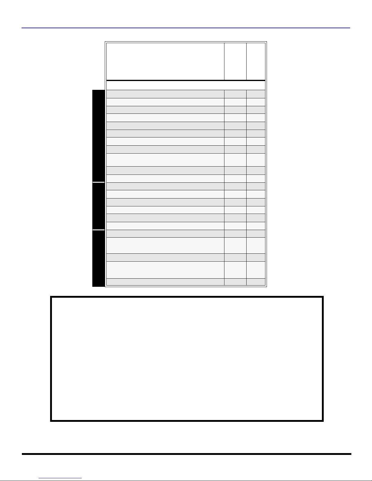
Feature Chart
MODELS
F
EATURE CHART
PT-51HX42C
FEATURES
MENU LANGUAGE ENG/SPAN/FR
PROTECTIVE SCREEN
2 TUNER SPLIT
2 TUNER PIP
VIDEO PICTURE MEMORY
VIDEO INPUT SKIP
CLOSED CAPTIONING
V-CHIP CAPABILITY
DIGITAL SCAN RATE
NTSC LINE - DOUBLER
VIDEO NORM
AUDIO NORM
STEREO
AI SOUND
BASS/BALANCE/TREBLE
SURROUND
BBE
A/V PROGRAM OUT
A/V IN
(REAR/FRONT)
AUDIO OUT
S-VHS INPUT
(REAR/FRONT)
A/V JACKS AUDIO SPECIAL FEATURES
COMPONENT INPUT
r r
r r
r r
r r
r r
r r
r r
r r
1080i,
480p
480p 480p
r r
r r
r r
r r
r r
r r
r r
r r
4
(3/1) 4(3/1)
r r
3
2/1
2 2
PT-61HX42C
1080i,
480p
3
2/1
IMPORTANT INFORMATION REGARDING THE USE OF VIDEO GAMES, COMPUTERS, OR
OTHER FIXED IMAGE DISPLAYS.
WARNING: The marking or retained image on the picture tube resulting from viewing fixed
image is not an operating defect and as such is not covered by Warranty.
The projection television is designed to display constantly moving images on the screen.
Continuous viewing of stationary images such as letter box pictures on standard screen TVs ( with
top/bottom bars), n on-expanded s tandard (4:3) pictures on wide screen TVs (with si de bars s hown
on each side of a n image), stock mark et report bars (ticker run ning at the bottom of the screen),
video game patterns, fixed scoreboards, bright station logos, on-line (Internet) or repetitive computer
style patterns should be limited.
The extended use of fixed image program material can cause permanent picture tube damage,
shown as a “shadow im age” viewable on normal program s. This type of irreversible pic ture tube
deterioration can be limited by performing the following steps:
• Limit the display of fixed image program material to no more than 15% of total viewing time per week.
• Turn the power off when not in use.
5 l
A
UTO SET UP MENU
Auto Set Up Menu
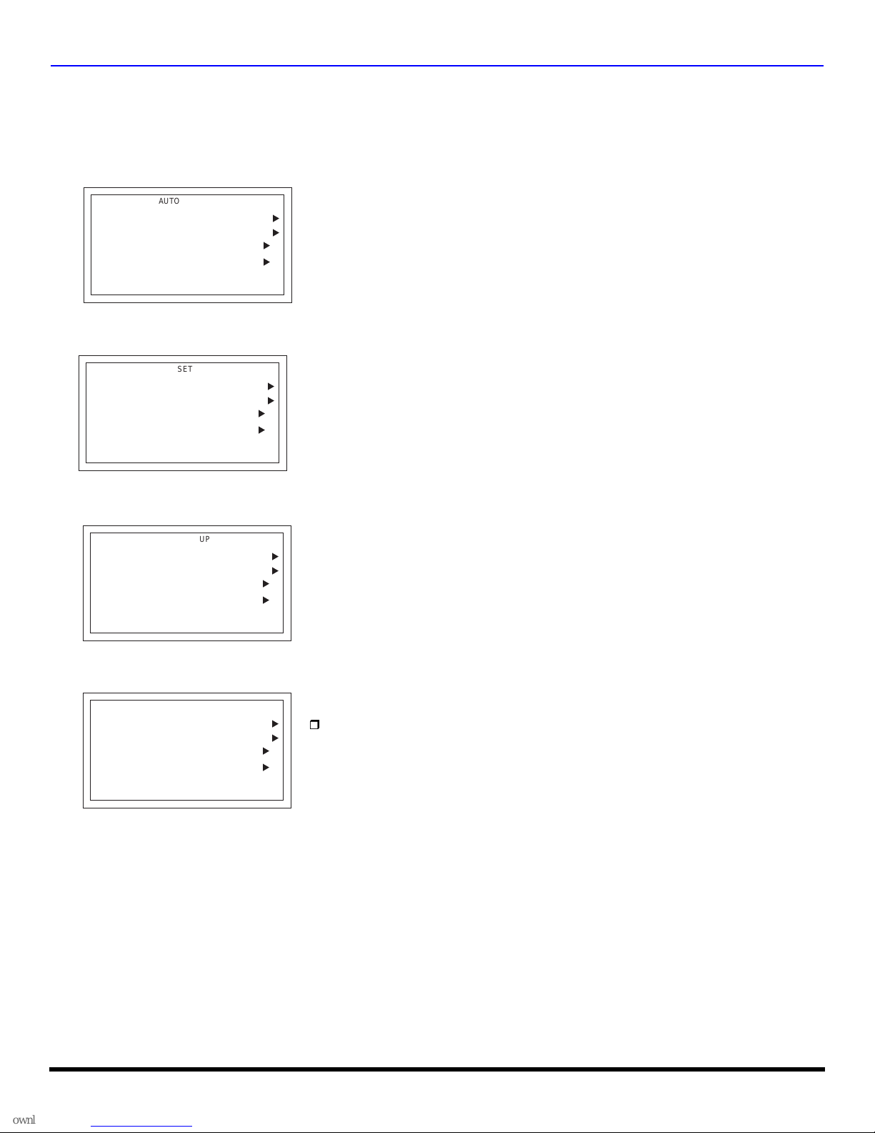
For your convenience, Auto Set up menu will be displayed on screen when the set is turned on for the first time. If needed,
follow the menus and procedures for setting up the features.
r IDIOMA/LANGUE - To change menu language to ENGLISH, SPANISH or FRENCH.
AUTO SET UP
IDIOMA/LANGUE
AUTO PROGRAM
CONVERGENCE
PRESS ACTION TO EXIT
r MODE - To select TV (antenna) or CABLE mode depending on the signal source.
AUTO SET UP
IDIOMA/LANGUE
AUTO PROGRAM
CONVERGENCE
PRESS ACTION TO EXIT
ENGLISH
CABLEMODE
ENGLISH
CABLEMODE
u
r Press VOL u to select English, Spanish or French.
u
u
u
u
r Press VOL u to select TV or CABLE.
u
u
u
r AUTO PROGRAM - To automatically program all channels with a signal.
AUTO SET UP
IDIOMA/LANGUE
AUTO PROGRAM
CONVERGENCE
PRESS ACTION TO EXIT
ENGLISH
CABLEMODE
u
r Press VOL u to start Auto Programming.
u
u
u
r CONVERGENCE -To adjust the center convergence, if needed.
AUTO SET UP
IDIOMA/LANGUE
AUTO PROGRAM
CONVERGENCE
PRESS ACTION TO EXIT
ENGLISH
CABLEMODE
u
r Press VOL u to display Convergence adjustment menu.
u
u
u
Note: Refer to page 28 for setting Convergence, if needed.
6 l
O
PTIONAL EQUIPMENT CONNECTIONS
Optional Equipment Connections
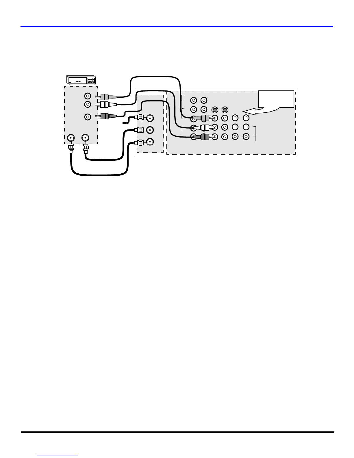
VCR Connection
Follow this diagram when connecting your television to a VCR only.
.
VCR
CONNECTIONS ON BACK OF THE PTV
VIDEO OUT
AUDIO OUT
ANT INANT OUT
L
R
ANT 1
Incoming
Cable
SPLIT OUT
ANT 2
AUDIO
VIDEO
Y
P
B
P
R
L
R
12
COMPONENT
VIDEO INPUTS
SVIDEO
INPUT 1INPUT 2INPUT
3
CABLES NOT SUPPLIED
Note: The remote control must be programmed with supplied codes to operate the VCR.
Viewing a television program
Procedure
1. Select ANT1 in the SET UP menu under Prog Chan (Program Channels).
2. Tune the television to the television program you want to view.
Viewing a video
Procedure
r Option A
1. Select ANT1 in the SET UP menu under Prog Chan.
2. Press the TV/VIDEO button on the remote control to select the video input (VIDEO 1, VIDEO 2, etc.) connected to your VCR.
3. Begin the video.
r Option B
1. Select ANT2 in the SET UP menu under Prog Chan.
2. Tune the television to Channel 3 or 4, depending on your VCR.
3. Begin the video.
Recording a television program
Procedure
r Option A (Recording and viewing the same program)
1. Select ANT2 in the SET UP menu under Prog Chan.
2. Tune the television to Channel 3 or 4, depending on your VCR.
3. Using the VCR, tune to the television program you want to record.
4. Begin recording.
r Option B (Recording one program while viewing another program)
1. Select ANT1 in the SET UP menu under Prog Chan.
2. Press the TV/VIDEO button on the remote control to select the video input (VIDEO 1, VIDEO 2, etc.) connected to your VCR.
3. Using the VCR, tune to the television program you want to record.
4. Begin recording.
5. Press the TV/VIDEO button on the remote control to switch back to TV mode.
6. Tune the television to the program you want to view.
PROG
OUT
AMP
VIDEO
L
R
Use either the
S-Video or Video
connection.
TO
AUDIO
7 l
O
PTIONAL EQUIPMENT CONNECTIONS
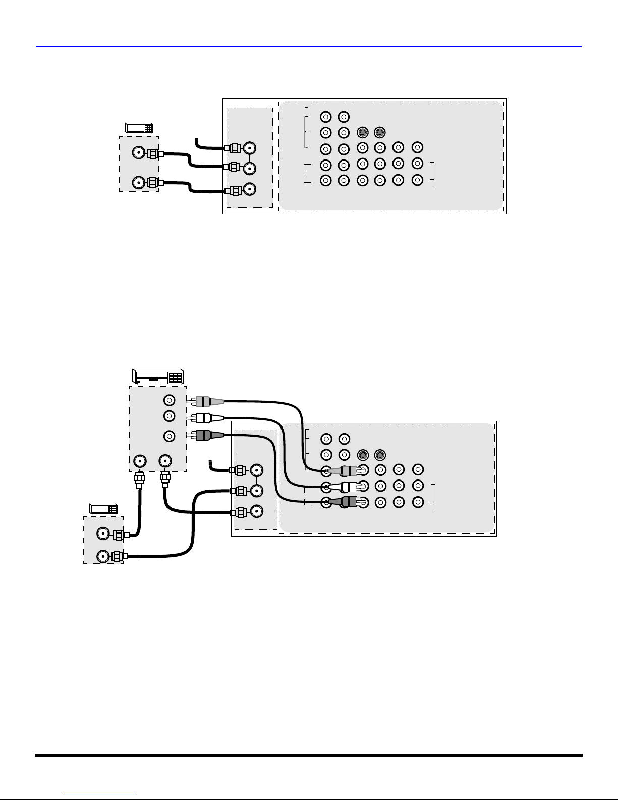
Cable Box Connection
Follow this diagram when connecting your television to a cable box only.
CONNECTIONS ON BACK OF THE PTV
AUDIO
VIDEO
Y
P
B
P
R
L
R
12
COMPONENT
VIDEO INPUTS
INPUT 1INPUT 2INPUT
CABLE BOX
INCOMING
CABLE
ANT IN
ANT OUT
CABLES NOT SUPPLIED
ANT 1
SPLIT OUT
ANT 2
Note: The remote control must be programmed with supplied codes to operate the cable box.
Viewing a premium (scrambled) cable channel
Procedure
1. Select ANT2 in the SET UP menu under Prog Chan (Program Channels).
2. Tune the television to Channel 3.
3. Using the cable box, tune to the premium cable channel you want to view.
Note: To use special features such as Favorite Channels and Channel Captions ANT1 must be selected in the SET UP
menu under Prog Chan.
VCR and Cable Box Connection
Follow this diagram when connecting your television to both a VCR and a cable box.
VCR
VIDEO OUT
SVIDEO
3
PROG
OUT
AMP
VIDEO
L
R
TO
AUDIO
CONNECTIONS ON BACK OF THE PTV
VIDEO
Y
P
B
P
R
L
AUDIO
R
COMPONENT
VIDEO INPUTS
CABLE BOX
ANT OUT
ANT IN
AUDIO OUT
ANT OUTANT IN
L
R
Incoming
Cable
SPLIT OUT
CABLES NOT SUPPLIED
ANT 1
ANT 2
Note: The remote control must be programmed with supplied codes to operate the VCR and cable box.
Viewing a premium (scrambled) cable channel
Procedure
1. Select ANT2 in the SET UP menu under Prog Chan (Program Channels).
2. Tune the television to Channel 3.
3. Using the cable box, tune to the premium cable channel you want to view.
Note: To use special features such as Favorite Channels and Channel Captions ANT1 must be selected in the SET UP
menu under Prog Chan.
12
SVIDEO
INPUT 1INPUT 2INPUT
3
PROG
OUT
AMP
VIDEO
L
R
TO
AUDIO
8 l
O
PTIONAL EQUIPMENT CONNECTIONS
VCR and Cable Box Connection (Contd.)
Recording a premium (scrambled) cable channel
Procedure
1. Select ANT2 in the SET UP menu under Prog Chan.
2. Press the TV/VIDEO button on the remote control to select the video input (VIDEO 1, VIDEO 2, etc.) connected to your VCR.
3. Turn the VCR ON.
4. Tune the VCR to Channel 3 or 4, depending on the switch setting on the back of VCR.
5. Using your cable box, tune to the premium cable channel you want to record.
6. Begin recording.
Note: To view a different channel while recording:
• Select ANT1 in the SET UP menu under Prog Chan.
• Press the TV/VIDEO button on the remote control to TV mode.
• Tune the television to a channel (except another premium cable channel).
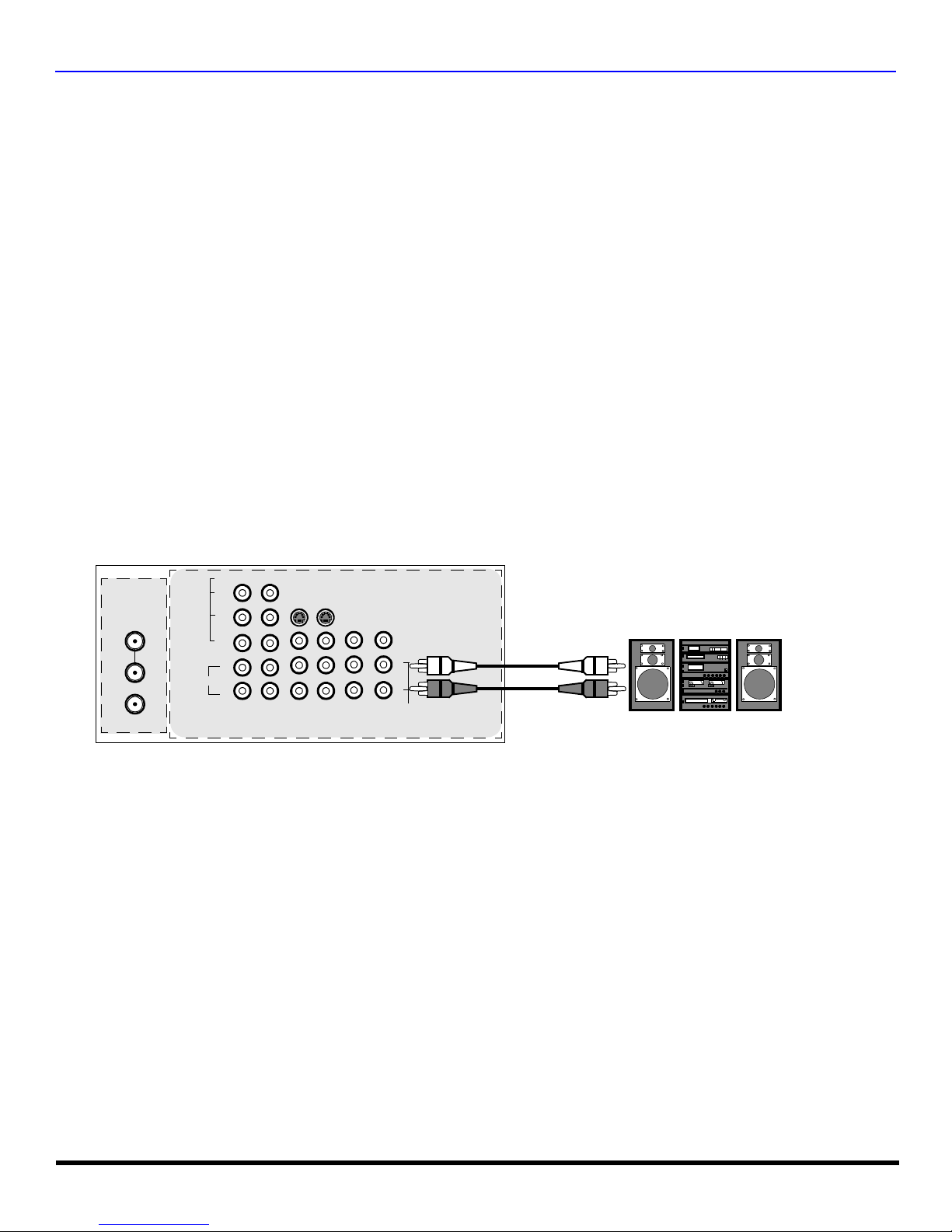
Amplifier Connection (TO AUDIO AMP)
To listen through a separate stereo system, connect an external audio amplifier TO AUDIO AMP outputs on back of television.
Note: TO AUDIO AMP terminals cannot be connected directly to external speakers.
Audio Adjustments
1. Select SPEAKERS ON located in the onscreen AUDIO menu.
2. Set amplifier volume to minimum.
3. Adjust television volume to desired level.
4. Adjust amplifier volume to match the television.
5. Select SPEAKERS OFF & VARIABLE AUDIO OUT from AUDIO menu.
6. Volume, mute, bass, treble and balance are now controlled through the television.
Note: Select SPEAKERS OFF & FIXED AUDIO OUT to c ontrol audio functions through the external ampl ifier.
CONNECTIONS ON BACK OF TV
CABLES NOT SUPPLIED
External Amplifier
ANT 1
SPLIT OUT
ANT 2
AUDIO
VIDEO
Y
P
B
P
R
L
R
12
COMPONENT
VIDEO INPUTS
SVIDEO
INPUT 1INPUT 2INPUT
3
PROG
OUT
AMP
VIDEO
L
R
TO
AUDIO
9 l
O
PTIONAL EQUIPMENT CONNECTIONS
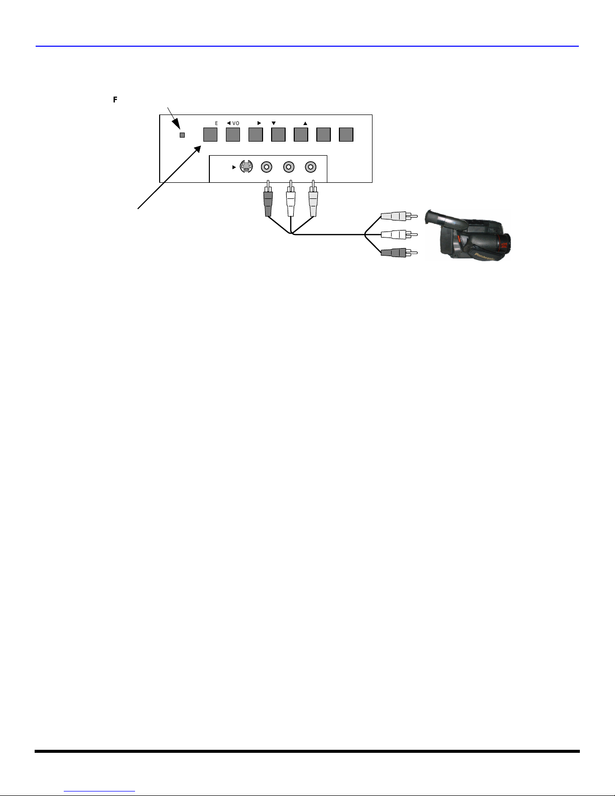
Front Control Panel
The front control panel can be used to access menus and switch video mode when the remote control is not available.
ON/OFF INDICA TOR
POWER ON/OFF
Note: The ON/OFF indicator LED (red) will be lit when set is on.
POWER
INPUT4
q
VOLUME
u
S-VIDEO VIDEO L-AUDIO-R
CHANNEL
u
ACTION TV/VIDEO
pt
CAMCORDER
Note: The S-VID EO connection provides higher quality picture. It overrides VIDEO 4 connections. U s e I NPUT 4, AU DIO L and R
with S-VIDEO connection.
Open the door on th e PTV front panel to use the connection s for your optiona l equipment. A second VCR, cam corder, a
video disc player, video game equipment or DSS equipment can also be connecte d to the A /V i nputs. Se e the manu al tha t
came with the optional equipment for details.
Procedure
1. Connect equipment to front Audio/Video input jacks.
2. Press TV/VIDEO button to select VIDEO 4 input mode.
3. Operate optional equipment as instructed in equipment manual.
10 l
O
PTIONAL EQUIPMENT CONNECTIONS
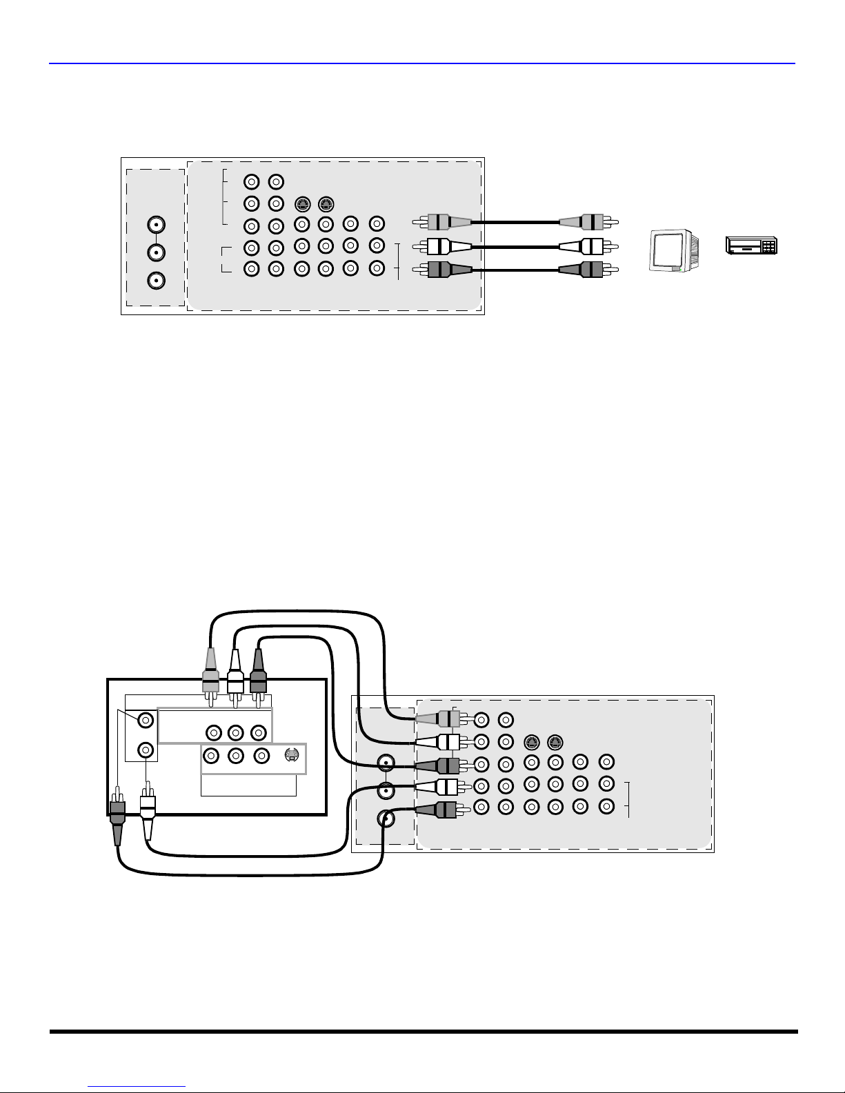
Program Out Connection (PROG OUT)
To use the television audio and video with optional equipment, connect the PROG OUT and TO AUDIO AMP connections on the back of
the television.
CONNECTIONS ON BACK OF TV
VIDEO
ANT 1
SPLIT OUT
ANT 2
AUDIO
Y
P
B
P
R
L
R
12
COMPONENT
VIDEO INPUTS
SVIDEO
INPUT 1INPUT 2INPUT
3
PROG
OUT
AMP
VIDEO
L
R
TO
AUDIO
CABLES NOT SUPPLIED
MONITOR
VCR
OR
Procedure
1. Connect optional equipment to PROG OUT and TO AUDIO AMP terminals.
2. PROG OUT terminal display is the same as onscreen display.
3. See optional equipment manual for further instructions for recording and monitoring.
Digital TV - Set-Top Box (DTV-STB) or DVD Connection
This television is capable of displaying 1080i and 480p DTV signals when connected to a DTV Tuner set-top-box (STB). In
order to view DTV programming, the STB must be connected to the component video inputs (Y, P
DTV signal must be available in your area. Select the output of the STB to either 1080i or 480p.
, PR) of the television. A
B
This television also utili zes a progressive scan doubler, which de-interlaces the NTS C signal and progr essively sca ns the
image. This allo ws you to sit close to the TV a nd not see the thin bl ack horizo ntal lines ( venetian blin d effect) asso ciated
with interlaced TV pictures.
Use this diagram to connect the Panasonic DTV-STB (Digital TV-Set-Top Box) or DVD Player to the back of your TV.
TERMINALS ON BACK OF DTV-STB OR DVD PLAYER
DTV INPUT TERMINALS ON BACK OF TV
CABLES NOT SUPPLIED
DIGITAL TV OUTPUT
MAIN
VIDEO
L-AUDIO-R
B
-VIDEO
PRP
Y
R-AUDIO-L
NTSC OUTPUT
ANT 1
S-VIDEO
SPLIT OUT
ANT 2
AUDIO
VIDEO
Y
P
B
P
R
L
R
12
COMPONENT
VIDEO INPUTS
SVIDEO
INPUT 1INPUT 2INPUT
3
PROG
OUT
AMP
VIDEO
L
R
TO
AUDIO
Note: There are 2 sets of three video inputs, Y, PB, and PR. Separate component color inputs provide luminance and color
separation. Use the L (left) and R (right) audio inputs.
11 l
PIP
L
AND SPLIT OPERATION
PIP and Split Operation
PIP Operation
This television includ es a two- tu ner Pic tur e In Picture (PIP) feature. This al lo ws y ou to wat ch two ( 2) li ve br oad ca sts at th e
same time with or without an external video source such as a VCR, cable box, etc.
r Connect incoming cable to ANT 1 input on back of TV
PIP
Main Picture
r Press to display PIP frame.
r Select channels for the PI P frame by pressing .
r Select channels for the Main picture by pressing
PIP Frame
or use the remote control numeric keypad.
SWAP
r Press to switch the PIP and MAIN PICTURE source.
Note:
Audio is from Main Picture only.
RECAL
r Press to view picture source status.
r Press to cancel PIP frame.
PIP
Split Operation
This feature lets you watch two different channels side by side with or without an external video source.
SPLIT
r Press to display Split screen.
r Select channels for the Split screen by pressing
PIP CH
Main Picture
with Audio
Note:
Split Picture
no Audio
Audio is from Main Picture only.
r Select channels for the Main picture by pressing
or use the remote control numeric keypad.
SWAP
r Press to switch the SPLIT SCREEN and MAIN
PICTURE source.
r Press to view picture source status.
RECALL
PIP CH
CH
or
CH
.
CH
or
CH
PIP and Split Operation With a Cable Box
To view premium (scrambled) cable channels through your cable box in the Main Picture:
Note: Use this procedure if you want to watch premium ca ble c hannels in the Main Picture whil e v ie wing a television program or video
in the PIP or Split frame.
Procedure
r Select ANT 2 in the SET UP menu under Prog Chan (Program Channels).
r Tune PTV to Channel 3.
PIP
r Press or on the remote control to display the PIP or Split frame.
Note: Audio is from the Main Picture only.
r Verify that the Cable box is ON.
r Choose channels for the Main Picture by tuning the cable box.
r Choose channels for the PIP or Split frame by pressing .
Note: Swap is not available when using the cable box to tune channels. If your cable box has video output, it can be
12 l
SPLIT
connected to the PTV to allow you to use all PIP or Split functions. See the equipment manual for more information.
r Press to cancel Split screen.
PIP CH
SPLIT
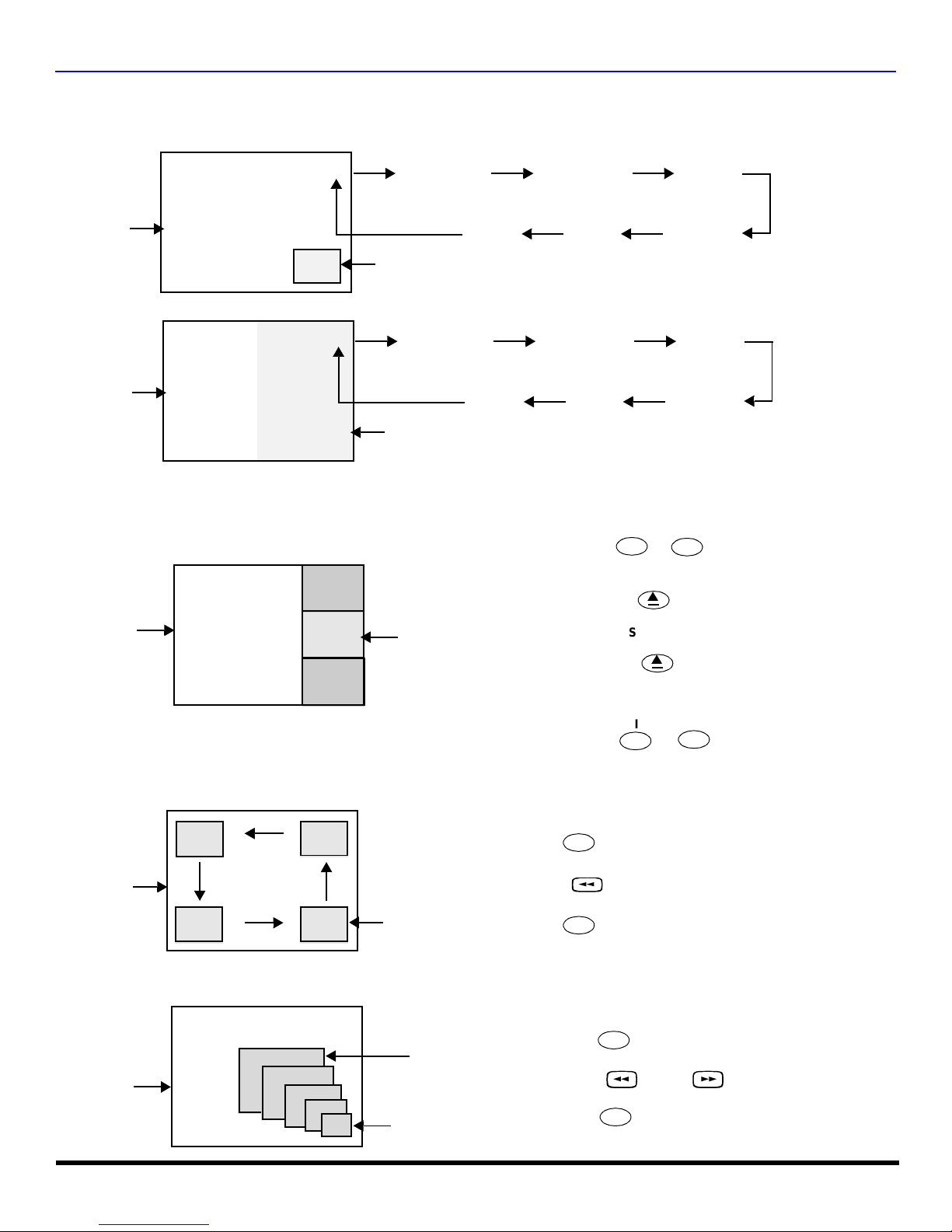
PIP and Split Operation (contd.)
TV/VIDEO Button (PIP and Split)
Press when PIP or Split frame is displayed to select desired input mode
PIP
AND SPLIT OPERATION
.
CH #
Main Picture
CH #
Main Picture
COMPONENT 1 COMPONENT 2 VIDEO 1
PIP Frame
COMPONENT 1
Split Frame
Search Button (PIP and Split)
This feature lets you scan through all available channels.
2
Main Picture
3
Search Frames
4
VIDEO 4
VIDEO 2VIDEO 3VIDEO 4
COMPONENT 2 VIDEO 1
VIDEO 2VIDEO 3
PIP
SPLIT
r Press or to display PIP or Split frame.
SEARCH
OPEN/CLOSE
r Press to display search frames.
r Press again to stop search feature.
p
SEARCH
OPEN/CLOSE
p
PIP or Split frame channel will be the last active
search frame.
PIP
SPLIT
r Press or to cancel PIP or Split frame.
Move Button (PIP only)
This feature is used to move PIP frame to one of four corners.
Main Picture
PIP MIN and PIP MAX Buttons
While PIP frame is displayed, press PIP MIN or PIP MAX button to vary the size of PIP frame.
Main Picture
PIP Frame
MAX
MIN
PIP
r Press to display PIP frame.
MOVE
r Press to position PIP frame to desired corner.
PIP
r Press to cancel PIP frame.
PIP
r Press to display PIP frame.
PIP MIN PIP MAX
r Press or to size PIP frame.
PIP
r Press to cancel PIP frame.
13 l
PIP
FREEZE
AND SPLIT OPERATION
PIP and Split Operation (contd.)
Freeze Button (Main Picture and PIP)
This feature is used to stop action in PIP frame or Main Picture.
Main Picture
Freeze frame
PIP and Split Mode Buttons Operational Chart
This chart indicates the buttons that are operational with PIP or Split.
PIP
r Press to display PIP frame.
FREEZE
r Press to stop PIP frame action.
Note: To stop action for Main Picture, press
r Press again to continue action.
r Press to cancel PIP frame.
TV/VCR
while PIP f rame is not displayed.
TV/VCR
PIP
FREEZE
TV/VCR
REMOTE
BUTTONS
PIP MODE SPLIT MODE
PIP MIN Size Smaller No Effect
PIP MAX Size Larger No Effect
FREEZE Freeze PIP Frame No effect
PIP CH Change Channel Change Channel
SEARCH Displays Search Frames Displays Search Frames
PIP Displays PIP Frame Displays PIP Frame
SPLIT Displays Split Frame Displays Split Frame
MOVE Mo ve PIP Frame No Effect
SWAP Swap With Main Picture Swap With Main Picture
Special Remote Buttons
ASPECT Button
The ASPECT bu tton on the re mote contr ol lets you selec t the picture s ize ratio to match progr amming forma t when usin g
DTV STB or DBS.
BBE Button
Press this button to turn the BBE
restores the dynamic range of musical passages to provide outstanding natural sound.
SAP Button
Press this button t o let you cy cle through d ifferent audio mo des. If you a re receiv ing a ster eo program and you press the
SAP button, you can cycle between STEREO and MONO.
sound feature On or Off. BBE® Sound technolog y enhances s peech intell igibility and
®
14 l
Remote Control Operation
V
C
R
DV
D
T
V
C
BL
D
B
S
A
U
X
R
C
V
R
D
T
V
7
4
1 2
5
8
0
9
6
3
POWER
R
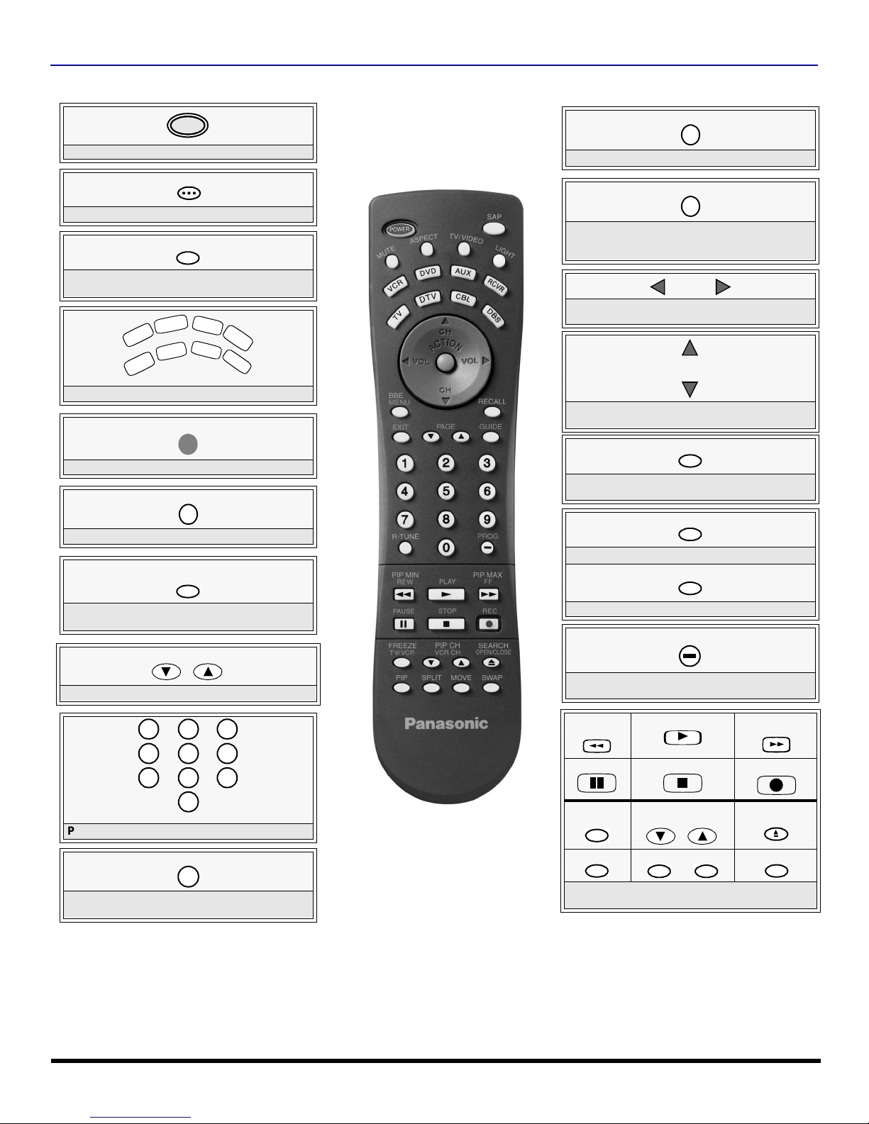
EMOTE CONTROL OPERATION
LIGHT
Press to turn ON and OFF.
SAP
Press to access second audio program.
MUTE
Press to mute sound. Press to display and
cancel CC (Closed Caption).
Press to select remote operation.
ACTION
Press to access menus.
TV/VIDEO
Press to select TV or input modes.
BBE
MENU
Press to illuminate remote buttons.
ASPECT
Select picture size (ratio) to match
programming format (DTV-STB and DBS
only).
VOL VOL
Press to adjust TV sound and navigate in
menus.
CH
CH
Press to select next or previous channel and
navigate in menus.
RECALL
Press to display time, channel, sleep timer,
and other options.
EXIT
DBS functions button.
GUIDE
BBE - Press to turn on or off.
MENU - Press to access DBS or DVD menus.
PAGE
DBS page up/down and DVD skip -/+ buttons.
Press numeric keypad to select any channel.
R-TUNE
Press to switch to previously viewed
channel or input modes.
Battery Installation
Use two AA batteries:
Remove battery cover by pushing in and up near arrow.
Install batteries matching (+) and (-) polarity si gns.
Replace the battery cover.
Note:
Incorrect installation can cause battery leakage and
corrosion that will damage the Remote Control
EUR7603Z30
Precautions
DBS functions button.
PROG
Press to enter minor number in a compound
number.
*PIP MIN
REW
PAUSE
*FREEZE
TV/VCR
*PIP
*Split or PIP function buttons
Component function buttons
PLAY
u
STOP
*PIP CH
VCR CH
*SPLIT *MOVE
• Replace batt eries in pairs.
• Do not mix battery types (zinc carbon
with alkaline).
• Do not recharge, heat, short-circuit,
disassemble, or burn batteries.
*PIP MAX
FF
REC
*SEARCH
OPEN/CLOSE
*SWAP
15 l
R
EMOTE CONTROL OPERATION
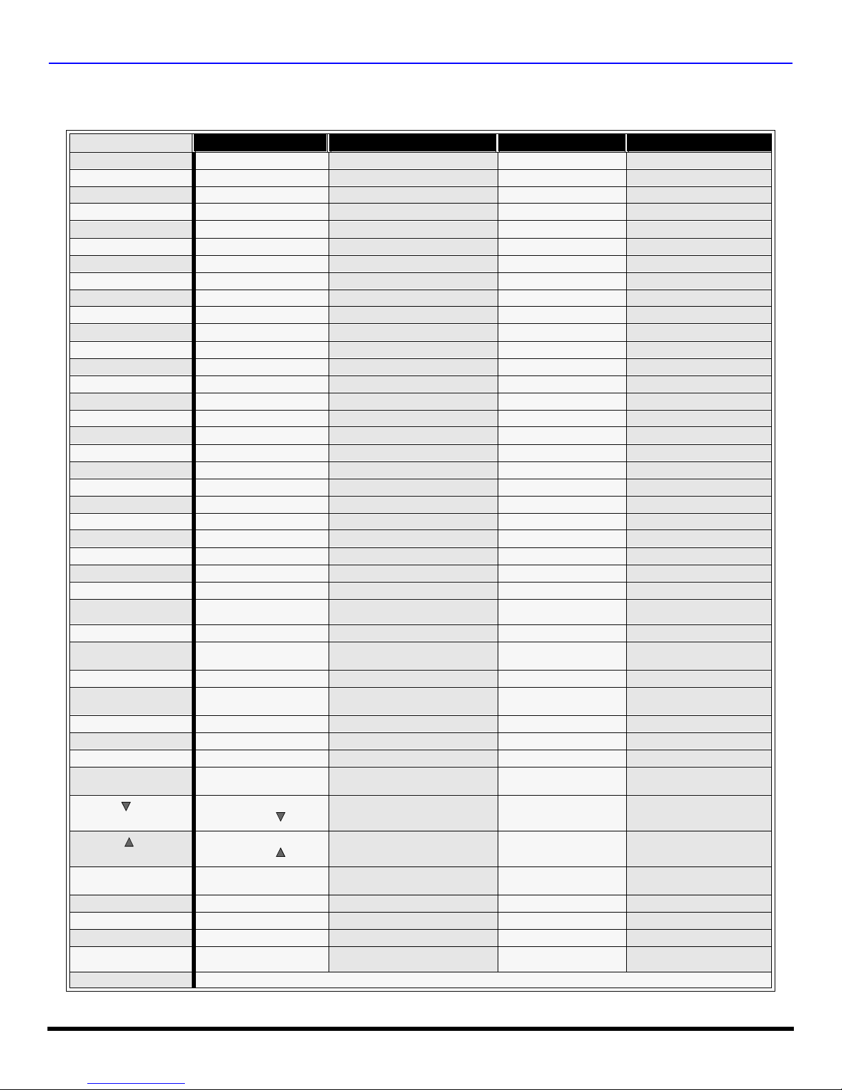
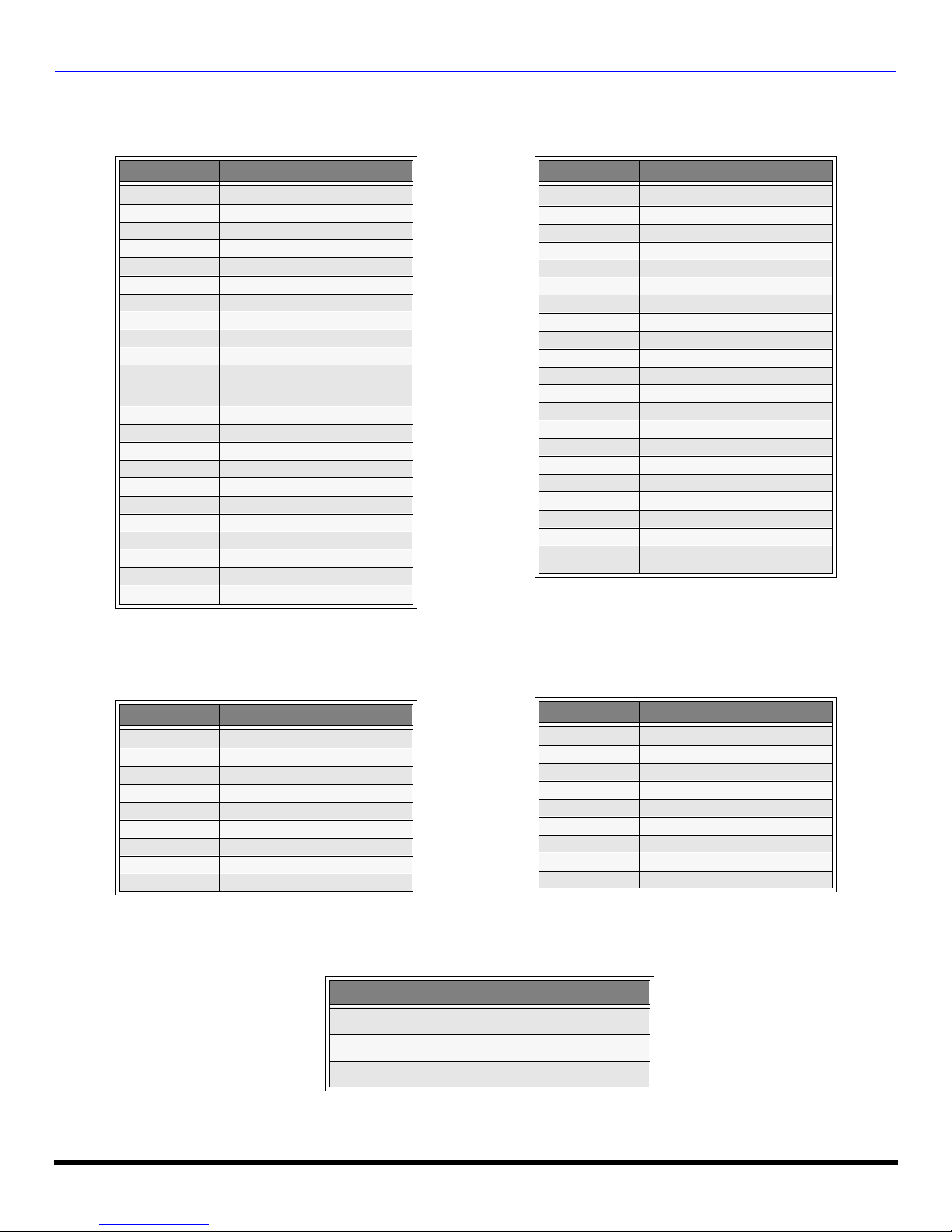
Mode Operational Key Chart
This chart defines which keys that are operational after programming (if needed), while in the selected remote control mode
TV, DTV, CABLE, DBS, VCR, DVD etc.
KEY NAME
POWER
SAP
MUTE
ASPECT
TV/VIDEO
CHAN UP
CHAN DOWN
VOL RIGHT
VOL LEFT
ACTION
BBE/MENU
RECALL
EXIT
PAGE DOWN
PAGE UP
GUIDE
1
2
3
4
5
6
7
8
9
0
R-TUNE
PROG
PIP MIN
<<REW
PLAY
PIP MAX
>>FF
PAUSE
STOP
RECORD
FREEZE
TV/VCR
PIP CH
VCR CH
PIP CH
VCR CH
SEARCH
OPEN/CLOSE
PIP
SPLIT
MOVE
SWAP
LIGHT
TV MODE DTV MODE CABLE MODE DBS MODE
POWER POWER POWER POWER
SAP ON/OFF - - MUTE TV MUTE CBL MUTE TV MUTE
TV ASPECT DTV ASPECT - DBS ASPECT
INPUT SWITCH TV INPUT SWITCH TV INPUT SWITCH TV INPUT SWITCH
CHANNEL UP - CABLE CHANNEL UP DBS NAVIGATION UP
CHANNEL DOWN - CABLE CHANNEL DOWN DBS NAVIGATION DOWN
ACTION ACTION ENTER DBS ACTION
BBE On or off STB MENU - STB MENU
DISPLAY STB PROGRAM INFO. TV DISPLAY STB PROG. INFO
DIGIT 1 STB DIGIT 1 DIGIT 1 DIGIT 1
DIGIT 2 STB DIGIT 2 DIGIT 2 DIGIT 2
DIGIT 3 STB DIGIT 3 DIGIT 3 DIGIT 3
DIGIT 4 STB DIGIT 4 DIGIT 4 DIGIT 4
DIGIT 5 STB DIGIT 5 DIGIT 5 DIGIT 5
DIGIT 6 STB DIGIT 6 DIGIT 6 DIGIT 6
DIGIT 7 STB DIGIT 7 DIGIT 7 DIGIT 7
DIGIT 8 STB DIGIT 8 DIGIT 8 DIGIT 8
DIGIT 9 STB DIGIT 9 DIGIT 9 DIGIT 9
DIGIT 0 STB DIGIT 0 DIGIT 0 DIGIT 0
PREVIOUS CHAN
OR VIDEO MODE
TV PIP MIN - - -
TV PIP MAX - - -
TV PIP FREEZE - - STB/DTV/SAT SW
PIP OR SPLIT
CHAN
PIP OR SPLIT
CHAN
SPLIT OR PIP SEARCH - - -
PIP ON/OFF - - SPLIT ON/ OFF - - MOVE PIP - - -
SWAP PIP OR SPLIT WITH
MAIN PICTURE
VOL + NAVIGATION RIGHT CABLE VOL + DBS NAVIGATION RIGHT
VOL - NAVIGATION LEFT CABLE VOL - DBS NAVIGATION LEFT
- DTV EXIT - STB EXIT
- STB PAGE DOWN - STB PAGE DOWN
- STB PAGE UP - STB PAGE UP
- - - DBS PROGRAM GUIDE
PREVIOUS DTV CHAN CABLE PREVIOUS STB PREVIOUS
- DTV PROGRAM/DASH - STB PROGRAM/DASH
- - - -
- - - -
- - - -
- - VCR RECORD STB RECORD
- CABLE CHANNEL DOWN DBS CHANNEL DOWN
- CABLE CHANNEL UP DBS CHANNEL UP
- - -
REMOTE BUTTONS
16 l

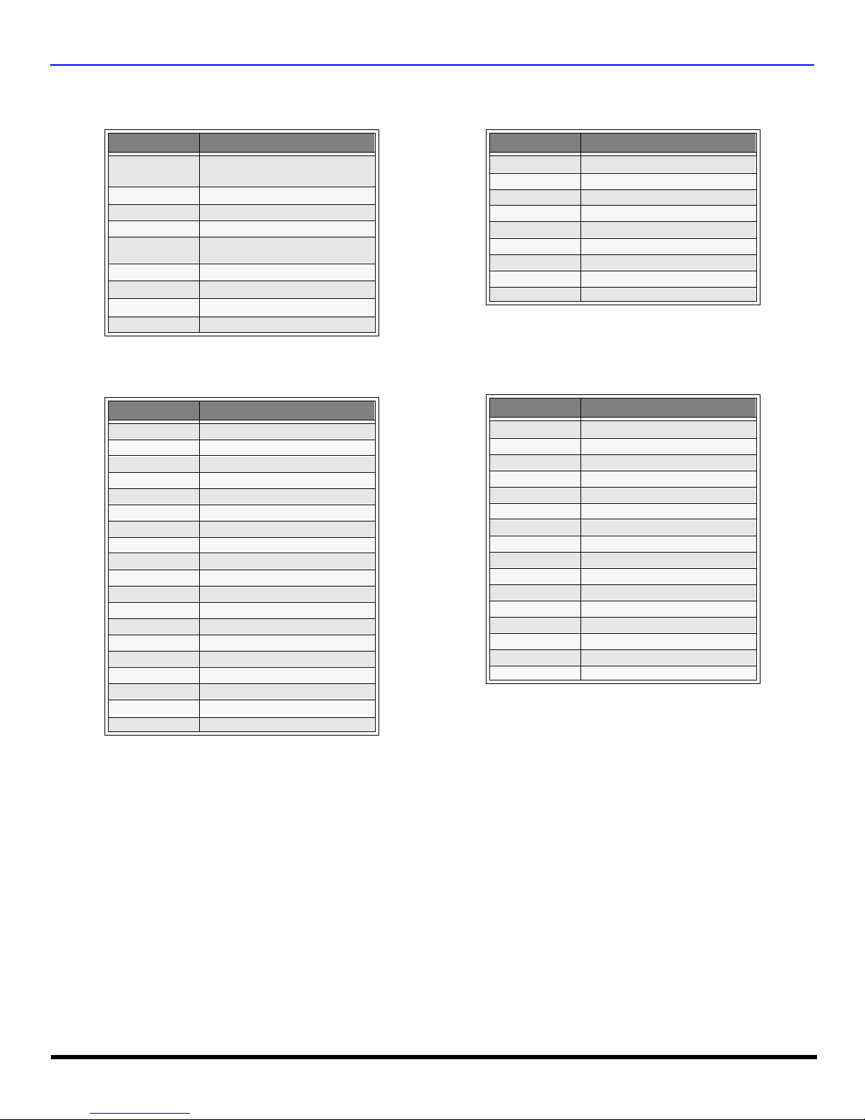
Mode Operational Key Chart (contd.)
KEY NAME VCR MODE
POWER
SAP
MUTE
ASPECT
TV/VIDEO
CHAN UP
CHAN
DOWN
VOL RIGHT
VOL LEFT
ACTION
BBE/MENU
RECALL
EXIT
PAGE
DOWN
PAGE UP
GUIDE
1
2
3
4
5
6
7
8
9
0
R-TUNE
PROG
PIP MIN
<<REW
PLAY
PIP MAX
>>FF
PAUSE
STOP
RECORD
FREEZE
TV/VCR
VCR/DBS
CHAN
VCR/DBS
CHAN
SEARCH
OPEN/
POWER POWER POWER POWER POWER POWER POWER
- - - - - - -
TV MUTE TV MUTE RCVR MUTE TV MUTE RCVR MUTE TV MUTE RCVR MUTE
- - - - - - -
TV INPUT SWITCH TV INPUT SWITCH TV INPUT SWITCH TV INPUT SWITCH TV INPUT SW TV INPUT SW
VCR CHANNEL UP NAVIGATION UP NEXT TRACK VCR CHANNEL UP - PVR UP TUN ER +
VCR CHAN DOWN
TV VOLUME +
TV VOLUME - NAVIGATION LEFT
TV ACTION SELECT - TV ACTION - SELEC T -
- DVD MENU - - - - -
ONSCREEN VCR
DISPLAY
- - - - - PVR Exit -
- SKIP - SKIP - - - - -
- SKIP+ SKIP+ - - - -
- TITLE NEXT DISC - - PVR GUIDE DIGIT 1 1 CHAPT. TRACK 1 DIGIT 1 - DIGIT 1 AV 1
DIGIT 2 2 CHAPT. TRACK 2 DIGIT 2 - DIGIT 2 AV 2
DIGIT 3 3 CHAPT. TRACK 3 DIGIT 3 - DIGIT 3 AV 3
DIGIT 4 4 CHAPT. TRACK 4 DIGIT 4 - DIGIT 4 AV 4
DIGIT 5 5 CHAPT. TRACK 5 DIGIT 5 - DIGIT 5 CD
DIGIT 6 6 CHAPT. TRACK 6 DIGIT 6 - DIGIT 6 TUNER
DIGIT 7 7 CHAPT. TRACK 7 DIGIT 7 - DIGIT 7 PHONO
DIGIT 8 8 CHAPT. TRACK 8 DIGIT 8 - DIGIT 8 TAPE
DIGIT 9 9 CHAPT. TRACK 9 DIGIT 9 - DIGIT 9 AUX
DIGIT 0 0 CHAPT. TRACK 0 DIGIT 0 - DIGIT 0 -
- - - - DECK A/B
- - - - -
VCR REWIND SKIP SEARCH <<
VCR PLAY DVD PLAY CD PLAY VCR PLAY TA PE PL AY PVR PLAY -
VCR FF
VCR PAUSE DVD PAUSE CD STILL/PAUSE VCR PAUSE TAPE PAUSE PVR PAUSE -
VCR STOP DVD STOP CD STOP VCR STOP TAPE STOP PVR STOP -
VCR RECORD - - VCR RECORD TAPE RECORD PVR RECORD -
TV/VCR SWITCH - - TV/VCR SWITCH -
VCR CHANNEL
DOWN
VCR CHANNEL UP SLOW + REPLAY VCR CHANNEL UP - - CENTER +
- OPEN/CLOSE OPEN/CLOSE - OPEN/CLOSE QUICK SKIP -
CLOSE
PIP
SPLIT
MOVE
SWAP
- - - - - - -
- - - - - - -
- - - - - - -
- - - - - - -
LIGHT
(DVD) (CD)
NAVIGATION
NAVIGATION
DVD DISPLA Y TIME FORMAT
SKIP SEARCH
SLOW - RANDOM
DVD MODE
DOWN
RIGHT
FF>>
PREVIOUS TRACK
TV/RCVR VOLUME
UP
TV/RCVR VOLUME
DOWN
SEARCH
REWIND
SEARCH
FF
REMOTE BUTTONS
R
EMOTE CONTROL OPERATION
AUX MODE
(VCR2) (TAPE) (PVR)
RCVR INPUT
VCR CHANNEL
DOWN
TV VOLUME +
TV VOLUME -
ONSCREEN VCR
DISPLAY
VCR REWIND TAPE REWIND PVR REWIND SURROUND -
VCR FF TAPE FF PVR FF SURROUND +
VCR CHANNEL
DOWN
- PVR DOWN TUNER -
RCVR
VOLUME +
RCVR
VOLUME -
- PVR ENTER -
- - CENTER -
PVR RIGHT
PVR LEFT
REPLAY
ZONES
RETURN TO
LIVE
INSTANT
REPLAY
VOLUME +
VOLUME -
RCVR
MODE
SW
RCVR
RCVR
-
-
-
17 l
R
EMOTE CONTROL OPERATION
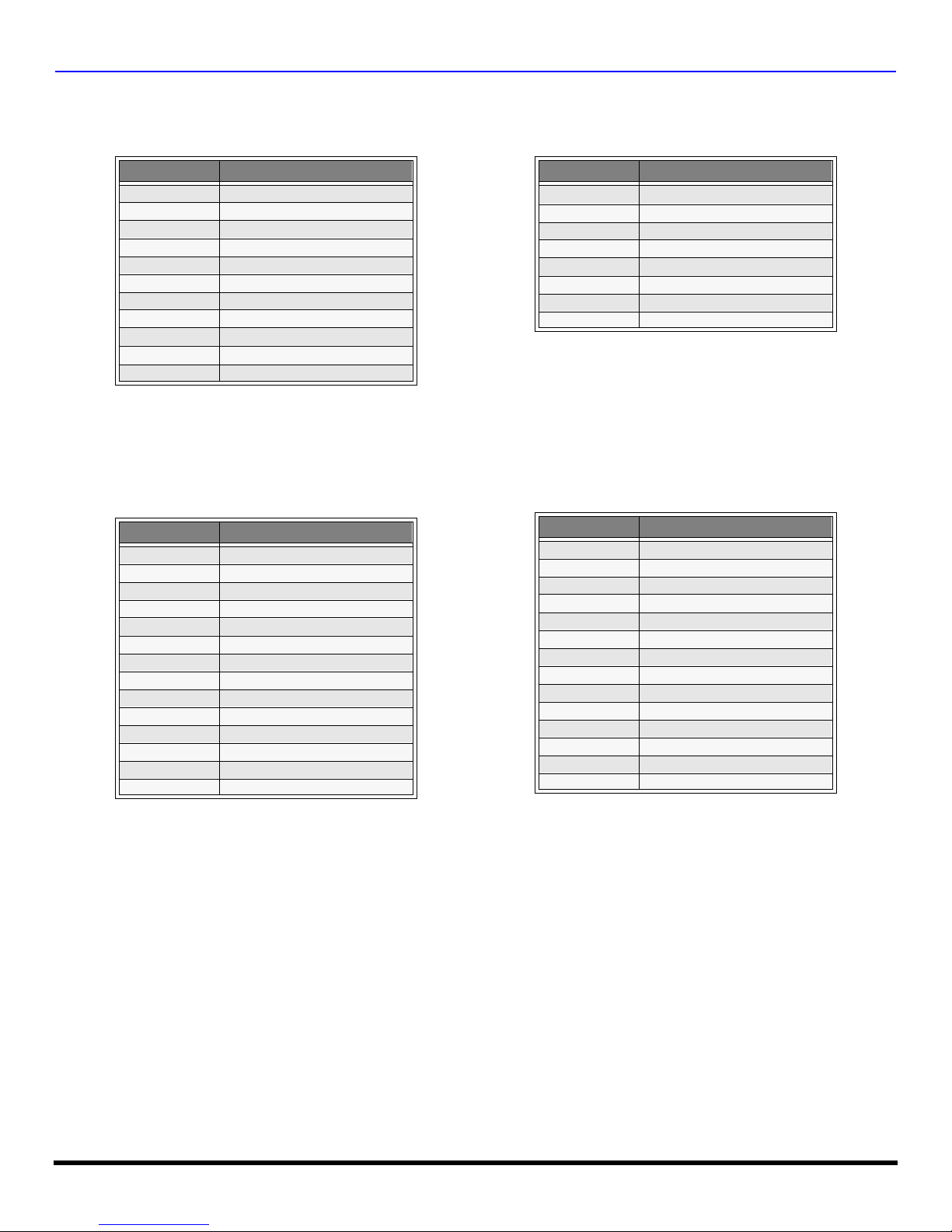
Programming The Remote
The Universal Remote Control ca n be programmed to operate many manufacturers’ co mponents, using the component
function buttons for VCR, DVD, AUX, RCVR, TV, DTV, CABLE or DBS. Follow the procedures for programming your
Remote Control with or without a code for the component.
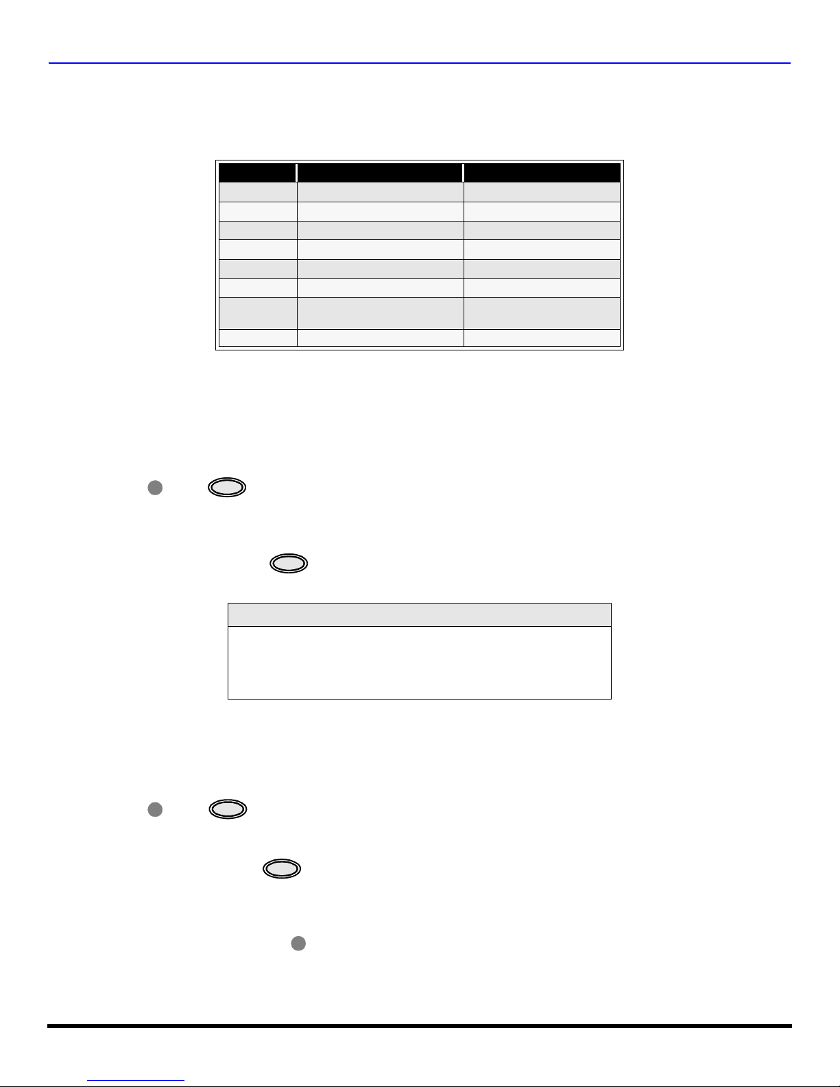
Default Modes For Remote Control
Device Operates Default
TV TV (Panasonic Only) Panasonic TV Codes
DTV DTV (Panasonic Only) Panasonic DTV Codes
CABLE CABLE (Preset) Panasonic CABLE Codes
DBS DBS (Preset) Panasonic DBS Codes
VCR VCR (Preset) Panasonic VCR Codes
DVD/CD DVD and CD (Preset) Panasonic DVD Codes
AUX
RCVR Audio Receiver (Preset) Panasonic RCVR Code
Personal Video Recorders,
Tape and VCR2
Panasonic Personal Video
Recorders Code
Determine the manufacturer of the component and look in the table for the code.
Programming With A Code
Procedure
• Confirm that the external component is plugged and operating.
• Turn the component off.
• Press and together, for at least 5 seconds.
ACTION
• Press appr op riate co mpo nen t butto n on the Rem ote Contr ol VCR , DVD ( CD), A UX ( VC R2 or TAPE), RCVR, DTV,
CABLE or DBS.
• Enter the 3-digit component code us ing the Re mot e Con tro l n umer ic ke yp a d (0 ~ 9 butto ns) .
• Press the Remote Control to test the component. If the procedure was successful, the component will
turn on.
POWER
POWER
Helpful Hints: Unsuccessful Code
If the component does not operate with the Remote Control, repeat
the procedure using another code. (Some brands have multiple
codes).
If an incorrect code is entered, or if the procedure ta kes longer than
30 seconds, the programming will fail.
Programming Without A Code
This procedure searches all codes and is called the “sequence method.”
• Confirm that the external component is plugged in and turned on.
• Turn the component off.
• Press and together, for at least 5 seconds.
ACTION
• Press appropriate component button on the Remote Control.
• Press
VOL u to move forward to the next code. Press t VOL to move backward.
• Press the Remo te Contr ol to test the compo nent. If the proce dure w as su ccessf ul, the compo nent will tur n
on.
Note: Repeat the above steps until the component code is found. It may take many attempts before the correct code
is found.
• After the code is found, press to store the code.
POWER
POWER
ACTION
18 l
R
EMOTE CONTROL OPERATION
Component Codes
The Universal Remo te Control i s capable of operating many component brands after ent ering a c ode. Som e components
may not operate because t he codes are not available due to limited memory. The Universa l Remote Control does not
control all features found in each model.
Write the code numbers from tables in this space. This will serve as a reference if you need
to program your Remote Control.
VCR
DVD
DVD (CD)
AUX (VCR 2)
AUX (TAPE)
RECEIVER
Brand Code
Admiral
Aiwa 332
Akai 314, 315, 316, 329
Audio Dynamic 311, 339
Bell & Howell 305, 313
Broksonic 320, 326
Canon 323, 325
Citizen 306
Craig 305, 306, 329
Curtis Mathes 324, 345
Daewoo 301, 324, 343
DBX 310, 311, 339
Dimensia 345
Emerson 303, 319, 320, 325, 326, 343
Fisher 305, 307, 308, 309, 313
Funai 320, 326, 334
GE 324, 333, 345
Goldstar 306
Gradiente 334
Hitachi 300, 323, 345
Instant Replay 323, 324
Jensen 339
JVC 310, 311, 334, 339
Kenwood 306, 310, 311, 339
LXI 300, 305, 306, 307, 308, 309
Magnavox 323, 324, 331
Marantz 310, 311, 339
Marta 306
Memorex 309, 324
MGA 338, 340, 341, 347, 348
Minolta 300, 345
Mitsubishi 338, 340, 341, 347, 348
Multitech 304, 347
NEC 310,311, 334, 339
Olympic 323, 324
Optimus 306, 321, 328, 335
335
CABLE DBS
Codes For VCR
Orion 320, 326
Panasonic 321, 322, 323, 324
J.C. Penney 300, 305, 310, 311, 324, 339, 345
Pentax 300, 311, 345
Philco 320, 323, 324, 326, 331, 343
Philips 323, 324, 331
Pioneer 323
Proscan
Quasar 321, 322, 323, 324
Radio Shack 305, 309, 324, 333, 336, 340
RCA
Realistic 305, 309, 324, 336, 340
Samsung 302, 304, 333
Sansui 320, 326, 339, 352
Sanyo 305, 309, 313
Scott
Sears 300, 305, 306, 307, 308
Sharp 335, 336
Shintom 317
Signature 2000 335
Singer 317
Sony 328, 329, 330
Sylvania 323, 324, 331
Tashiro 306
Tatung 310, 311, 339
Teac 310, 311, 339
Technics 321, 322, 323, 324
Teknika 324
Toshiba 301, 346
Vector Research 311
Wards 306, 309, 335, 336, 344
Yamaha 305, 310, 311, 339
Zenith 306, 344
Brand Code
300, 301, 302, 323, 324, 331, 333,
345, 346
300, 301, 302, 323, 324, 331, 333,
345, 346
301, 302, 304, 309, 320, 326, 338,
340, 347, 348
19 l
R
EMOTE CONTROL OPERATION
Component Codes (contd.)
Codes for Cable Box
Brand Code
ABC 124
Archer 125, 132
Cableview 105, 132
Citizen 105, 122
Curtis 112, 113
Diamond 124, 125, 1 32
Eagle 129
Eastern 134
GC Brand 105, 132
Gemini 122
General
Instrument/
Jerrold
Hamlin 112, 1 18, 140, 141, 142, 145
Hitachi 103, 124
Macom 103, 104, 105
Magnavox 133
Memorex 130
Movietime 105, 132
Oak 102, 137, 139
Panasonic 109, 110, 114
Philips 106, 107, 128, 129, 130
Pioneer 101, 116
Pulsar 105, 132
111, 119, 120, 121, 122, 123, 124,
125, 126, 127
Brand Code
Puser
RCA 115
Realistic 132
Regal 112, 118, 140, 141, 142, 145
Regency 134
Rembrandt 105, 132, 137
Samsung 105
Scientific Atlanta 111, 112, 113
Slmark 101, 105
Sprucer 105, 11 0
Stargate 105, 132
Teleview 101, 105
Texscan 144
Tocom 135
Toshiba 104
Unika 125, 132
Universal 122, 132
Videoway 106
Viewstar 129, 130
Zenith 100, 11 7
Zenith / Drake
Satellite
132
100
Brand Code
Denon 100
Ferguson 101
JVC 109
Mitsubishi 105
Nordmende 101
Panasonic 100
Philips 103
Pioneer 102
RCA 101
Codes for DVD
Brand Code
Saba
Samsung 110
Sharp 108
Sony 104
Technics 100
Thomson 101
Toshiba 103
101
Yamaha 100
Zenith 107
Codes for Personal Video Recorders
Brand Code
Panasonic Replay TV 100
Philips Tivo 101
Sony Tivo 102
20 l
Component Codes (contd.)
Codes for DBS
R
EMOTE CONTROL OPERATION
Brand Code
Dish Network
(Echostar)
Echo Star 105
Express VU 105, 115
G.E. 106
G.I. (General
Instrument)
Gradiente 114
Hitachi 103, 111, 112
HNS (Hughes) 103
Magnavox 101, 102
105, 115, 116
108
Brand Code
Admiral 226
Aiwa 233, 235
Carver 229
Denon 242
Emerson 239
Fisher 205
Harman/Kardon 219, 220, 221, 223
Hitachi 207
Jensen 234
JVC 240, 241, 245
Kardon 223
Kenwood 200, 201, 211, 245
LXI/Sears 236
Magnavox 229, 232
Marantz 229
McIntosh 221
Nakamichi 210
Onkyo 214, 215
Optimus 208, 218, 220, 222
Codes for CD
Brand Code
Panasonic
Phillips 101, 102
Primestar 108
Proscan 106, 109, 110, 113
RCA 106, 109, 110, 113
Sony 107
Star Choice 103, 108
Thoshiba 100
Uniden 101, 102
104
Brand Code
Panasonic 224, 22 5, 227
Philips 229, 230
Pioneer 208
Quasar 224, 225, 227
RCA 231, 237, 238, 247
Sansui 210, 246
Sanyo 205
Scott 210, 246
Sharp 242, 243
Sherwood 220
Sony 228
Soundesign 244
Teac 212, 216, 218
Technics 224, 225, 227
Victor 240, 241, 245
Yamaha 202,203, 204
21 l
R
EMOTE CONTROL OPERATION
Component Codes (contd.)
Codes for Cassette Deck
Brand Code
Aiwa 223, 224, 225
Denon 231
Fisher 203
Jensen 214
JVC 229, 230
Kenwood 200, 207
Marantz 202
Nakamichi 205
Onkyo 208, 209, 213
Panasonic 216, 21 8
Philips 222
Brand Code
Admiral 120
Aiwa 125, 126
Denon 134, 135, 136
Fisher 104
Garrard 113
Harman Kardon 115, 123
Jensen 129
JVC 132, 133
Kenwood 100, 108
Magnavox 127
Marantz 124
Mclntosh 116
Nakamichi 106
Onkyo 109, 114
Brand Code
Pioneer 204
RCA 226, 227, 228
Sansui 205, 210
Sharp 231
Sony 219, 220
Teac 210, 211, 215
Technics 216, 218
Yamaha 201, 202
Codes for Receivers
Brand Code
Optimus 103, 127, 130, 131
Panasonic 118, 119, 121
Philips 123
Pioneer 105, 107
Quasar 118, 119, 121
RCA 103, 105, 127, 130, 131
Sansui 103, 111, 139
Sharp 134, 137
Sony 122
Soundesign 138
Teac 111, 112, 113
Technics 118, 119, 121
Victor 132, 133
Yamaha 101, 102
22 l
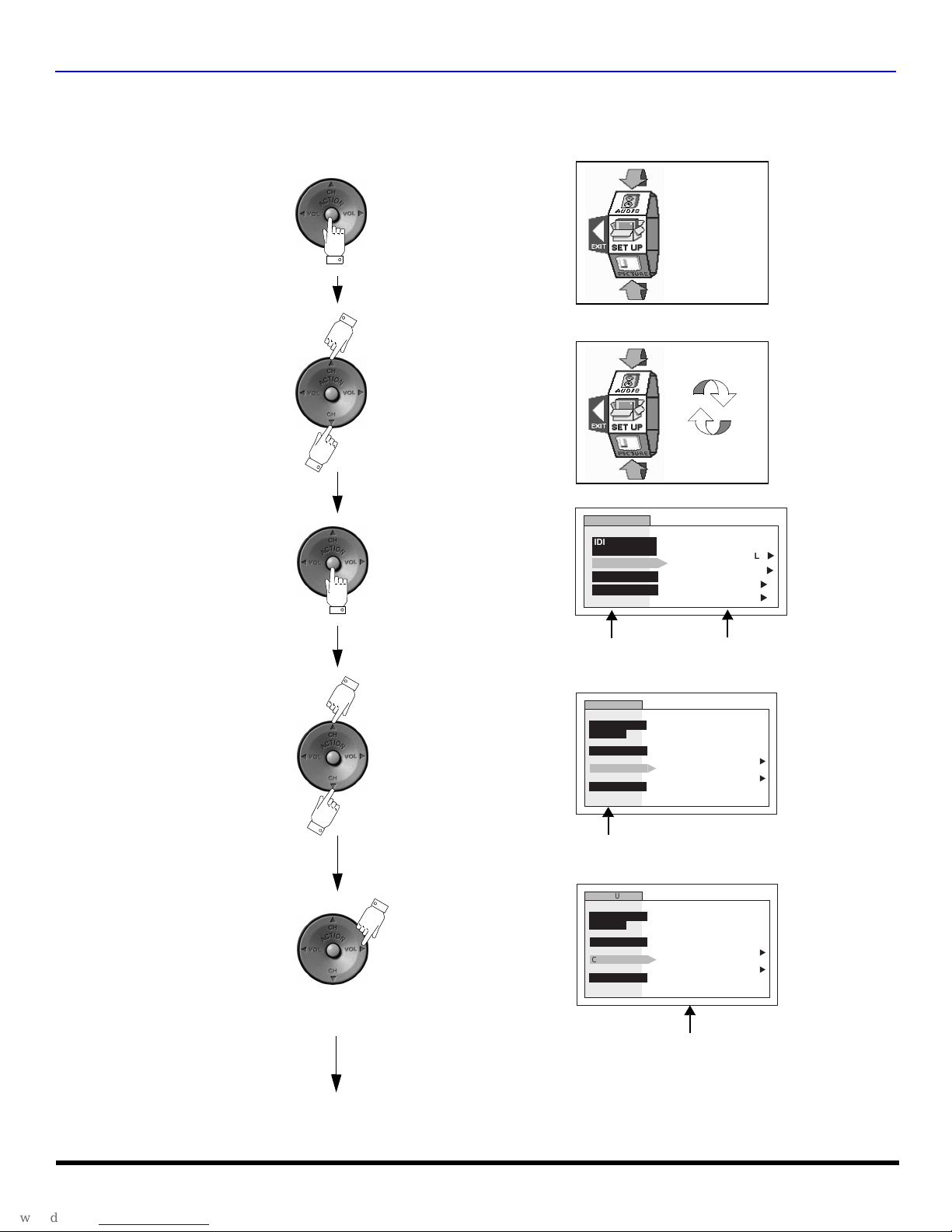
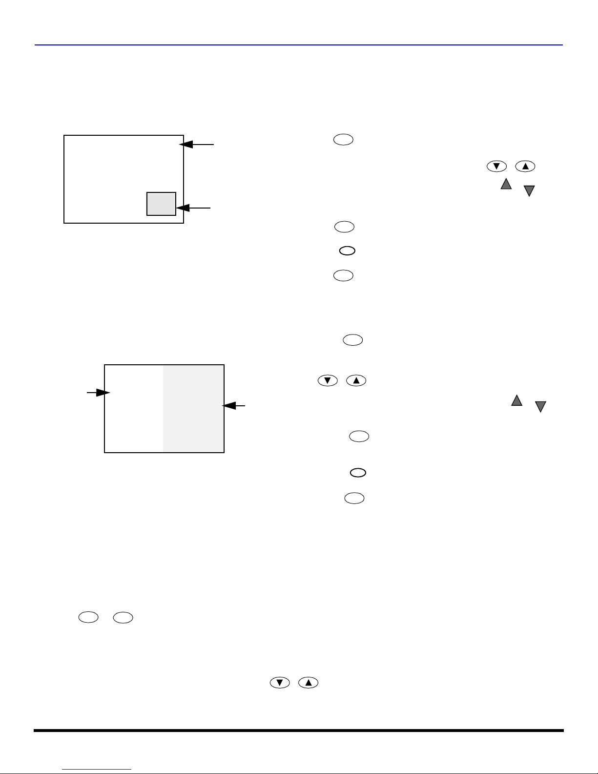
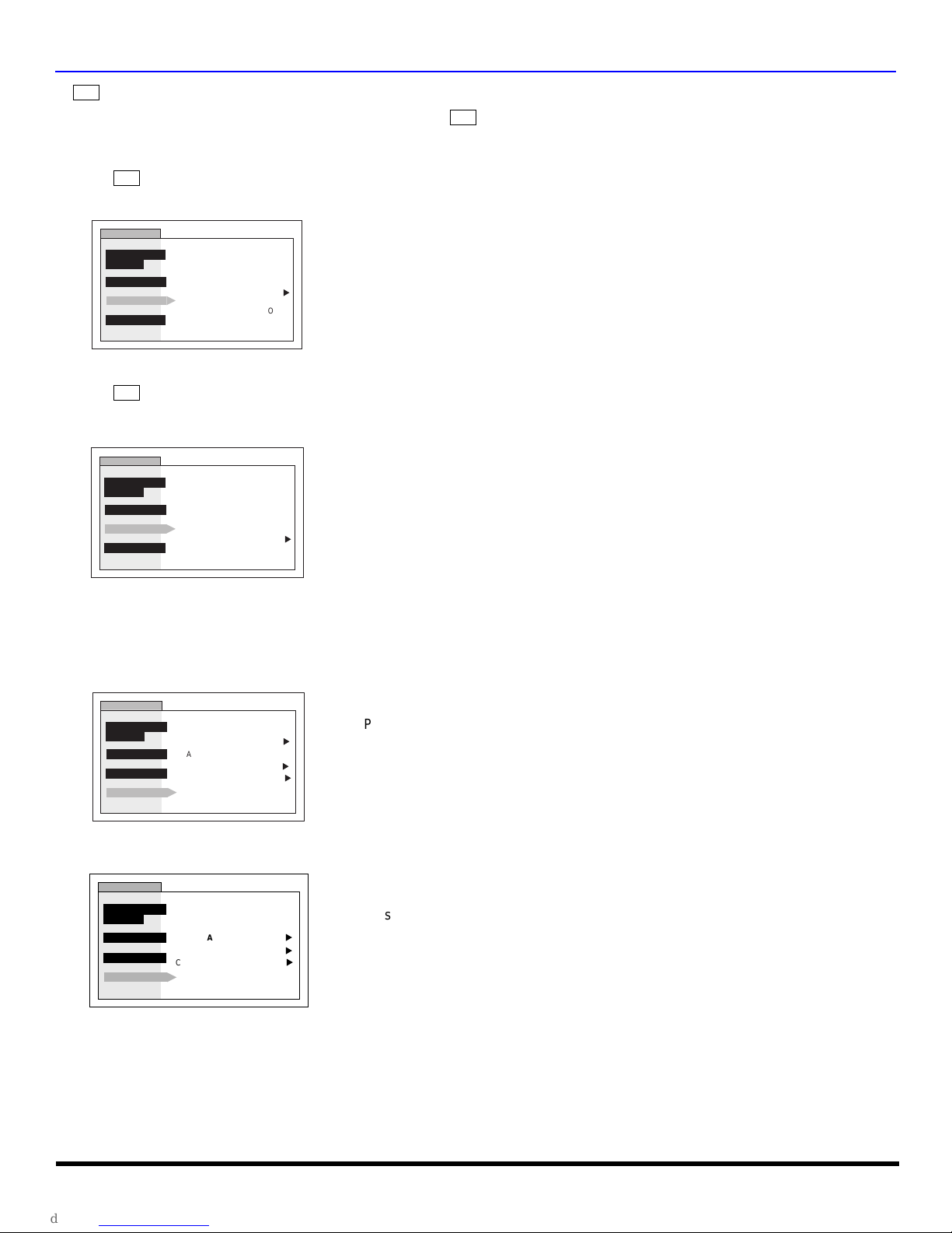
Roller Guide Menu Navigation
Press to display the roller guide
Press to rotate to desired icon.
menu.
R
OLLER GUIDE MENU NAVIGATION
Press to display main menu
and submenus field.
Press to select desired main
menu feature.
Press to enter submenu field.
SETUP
IDIOMA/
LANGUE
PROG CHAN
CC
OTHER ADJ.
Main Menu
Field
SETUP
IDIOMA/
LANGUE
PROG CHAN
CC
OTHER ADJ.
Main Menu
SETUP
IDIOMA/
LANGUE
PROG CHAN
CC
OTHER ADJ.
MODE
ANTENNA ANT1
AUTO PROGRAM
MANUAL PROGRAM
Submenu
Field
CC ON MUTE
CC MODE
CC ON MUTE
CC MODE
CABLE
NO
OFF
NO
OFF
u
u
u
u
u
u
u
u
Contd.
Submenu field
23 l
R
OLLER GUIDE MENU NAVIGATION
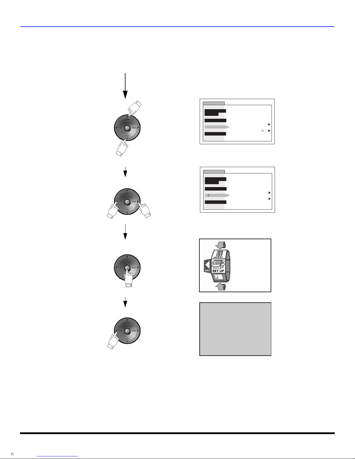
Roller Guide Menu Navigation (contd.)
Contd.
Press to select desired
Press to select or adjust.
submenu feature.
SETUP
IDIOMA/
LANGUE
PROG CHAN
CC
OTHER ADJ.
SETUP
IDIOMA/
LANGUE
PROG CHAN
CC
OTHER ADJ.
CC ON MUTE
CC MODE
CC ON MUTE
CC MODE
NO
OFF
NO
u
u
u
C1
u
Press twice to return to
the roller guide.
Press to exit roll er guide.
NORMAL PICTURE
24 l
R
OLLER GUIDE ICONS
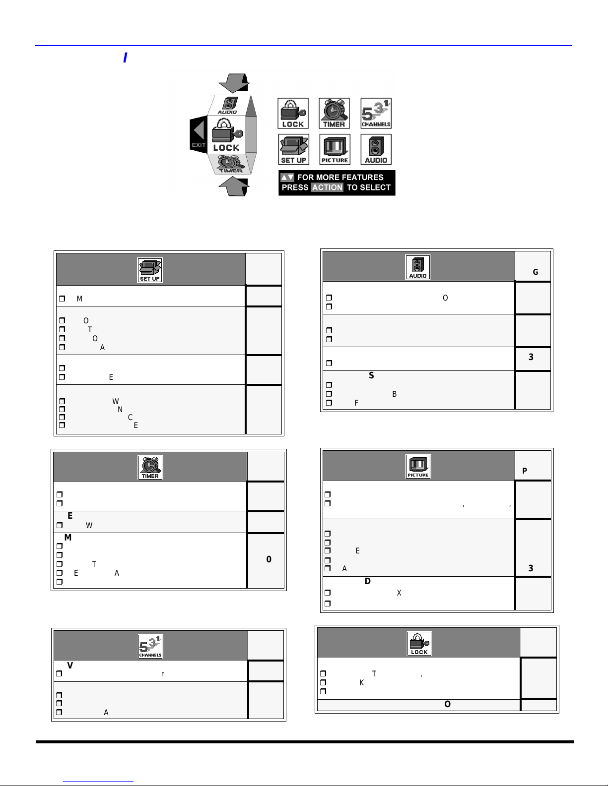
Roller Guide Icons
ROLLER GUIDE MENU SELECTIONS
Roller Guide Icon Menus
These charts list all menus under each Roller Guide Icon and which pages to refer to for menus description.
IDIOMA/LANGUE
r
MODE - (ENGLISH, FRANÇAIS, ESPAÑOL)
PROG CHAN
r
MODE - (TV or CABLE)
r
ANTENNA - (ANT1 or ANT2)
r
AUTO PROGRAM
r
MANUAL PROGRAM
CC (CLOSED CAPTIONED)
r
CC ON MUTE
r
CC MODE
OTHER ADJ.
r
AUTO POWER
r
CHAN BANNER
r
CONVERGENCE 1
r
CONVERGENCE 2
CLOCK SET
r
TIME
r
DAY
SLEEP
r
HOW LONG?
TIMER1 or TIMER2
r
DAY
r
ON TIME
r
OFF TIME
r
ENTER CHANNEL
r
SET
REFER
TO
PAGE
26
26
27
27
27
28
29
REFER
TO
PAGE
30
30
30
AUDIO ADJ.
r
MODE - (STERO, SAP or MONO)
r
BASS, TREBLE, BALANCE or NORMAL
OTHER ADJ.
r
AI SOUND
r
BBE
SURROUND
r
MODE
SPEAKERS
r
ON
r
OFF & VARIABLE AUDIO OUT
r
OFF & FIXED AUDIO OUT
VIDEO ADJ
r
PIC MODE
r
COLOR, TINT, BRIGHTNESS, PICTURE,
SHARPNESS OR NORMAL
OTHER ADJ1
r
COLOR TEMPERATURE
r
NATURAL COLOR
r
VIDEO NR
r
3D Y/C FILTER
r
ASPECT
OTHER ADJ2
r
COLOR MATRIX
r
VM
REFER
TO
PAGE
35
35
35
35
REFER
TO
PAGE
31
31
31
31
32
32
32
FAVORITES
r
CHANNEL SCAN (ALL or FAV)
CAPTION
r
PRESET CAPTION
r
MANUAL CAPTION
r
INPUT LABEL
REFER
TO
PAGE
33
34
MODE
r
LOCK SET - (OFF, ALL, CHANNEL, GAME)
r
BLOCK PROGRAM
r
HOW LONG?
V-CHIP OPERATION 37
REFER
TO
PAGE
36
25 l
R
OLLER GUIDE ICON MENU OPERATION
Roller Guide Icon Menu Operation
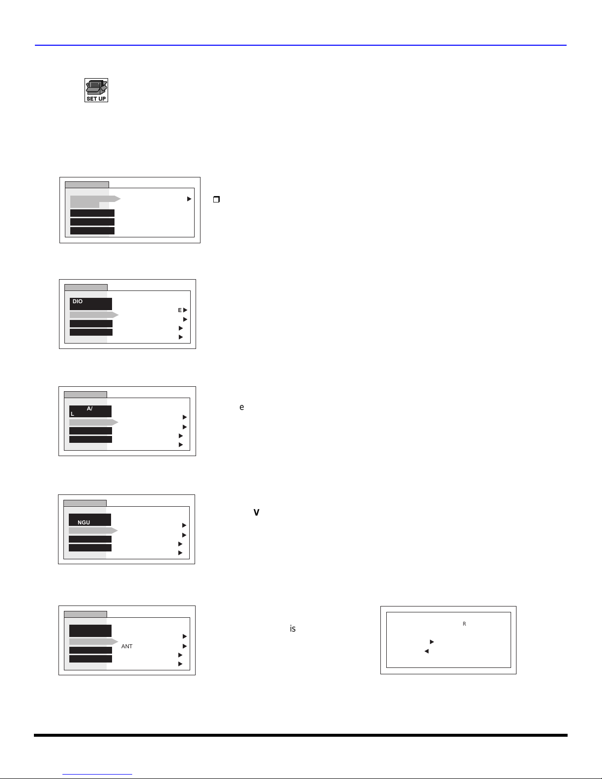
SET UP
Note: Refer to page 23 for Roller Guide Menu Navigation procedures.
IDIOMA/LANGUE (Menu Languages)
r In SET UP Menu, select IDIOMA/LANGUE to change menu language to ENGLISH, ESPAÑOL (Spanish) or
FRANÇAIS (French).
SET UP
IDIOMA/
LANGUE
PROG CHAN
CC
OTHER ADJ.
Prog Chan (Program Channels)
r MODE - To select TV (antenna) or CABLE mode depending on the signal source.
SETUP
IDIOMA/
LANGUE
PROG CHAN
CC
OTHER ADJ.
MODE ENGLISH
MODE
ANTENNA ANT1
AUTO PROGRAM
MANUAL PROGRAM
CABLE
u
u
u
r Press VOL u to select English, Spanish or French.
u
u
r Press VOL u to select TV or CABLE.
r ANTENNA - To select either ANT1 or ANT2.
SETUP
IDIOMA/
LANGUE
PROG CHAN
CC
OTHER ADJ.
MODE
ANTENNA ANT1
AUTO PROGRAM
MANUAL PROGRAM
CABLE
u
u
u
u
r Press VOL u to select ANT2 or ANT1.
r AUTO PROGRAM - To automatically program all channels with a signal.
SETUP
IDIOMA/
LANGUE
PROG CHAN
CC
OTHER ADJ.
MODE
ANTENNA ANT1
AUTO PROGRAM
MANUAL PROGRAM
CABLE
u
u
r Press VOL u to start AUTO PROGRAM.
u
u
r MANUAL PROGRAM - To manually add or delete channels.
SETUP
IDIOMA/
LANGUE
PROG CHAN
CC
OTHER ADJ.
MODE
ANTENNA ANT1
AUTO PROGRAM
MANUAL PROGRAM
CABLE
r Press VOL u to display next menu.
u
u
u
u
MANUAL PROGRAM
ENTER CHANNEL 3
TO ADD
u
u
TO DELETE
26 l
Note: Use Remote numeric keypad to enter channel
numbers.
R
OLLER GUIDE ICON MENU OPERATION
CC
(Closed Captioning)
This television co ntains a bui lt-i n de co der th at d is pl ay s (Cl ose d Ca pti oned) text across the s cr ee n ( whi te or co lo re d
CC
letters on black backgr ound). It allows th e viewer to read the dialogue of a tele vision program or other informati on. The
program viewed must include Closed Captioning for the feature to work.
CC
r On Mute - Activates the onscreen Closed Caption feat ure when the MUTE button on the remote control is
pressed. To deactivate press MUTE button again.
SETUP
IDIOMA/
LANGUE
PROG CHAN
CC
OTHER ADJ.
CC
r Mode - Activates the onscreen Closed Caption feature by selecting one of the following modes.
CC ON MUTE
CC MODE
NO
OFF
u
r Press VOL u to select C1,C2 C3, C4 or NO.
Note: This feature only functions when the Closed Caption Mode is OFF.
Recommended set up for Closed Caption when using the MUTE button:
• CC ON MUTE: C1
• CC MODE: OFF
r Press VOL u to select:
SETUP
IDIOMA/
LANGUE
PROG CHAN
CC
OTHER ADJ.
CC ON MUTE
CC MODE
NO
OFF
u
• OFF - When Closed Caption is not desired.
• C1 - For vide o rela te d info rma tio n to b e dis playe d, up to 4 l ine s onsc reen at
a time. (It does not block relevant parts of the picture). Text may be in any
language.
• C2 to C4 - For other modes of video related information.
• T1 to T4 - For program guide and other information to be displayed, when
available. (Blocks a large portion of the picture on the television screen).
Note: C1 mode is recomm ended for viewing Closed Caption.
Other Adjustments
r AUTO POWER ON - Select SET to power up the TV at the same time as the Cable box or other compo nents or
select OFF.
SET UP
IDIOMA/
LANGUE
PROG CHAN
CC
OTHER ADJ.
AUTO POWER ON
CHAN BANNER OFF
CONVERGENCE 1
CONVERGENCE 2
SET
u
u
u
r Press VOL u to select OFF or SET.
r CHAN BANNER - Select ON to display onscreen banner when changing channels.
SET UP
IDIOMA/
LANGUE
PROG CHAN
CC
OTHER ADJ.
AUTO POWER ON
CHAN BANNER ON
CONVERGENCE 1
CONVERGENCE 2
SET
u
u
u
r Press VOL u to select ON or OFF.
Note: Press RECALL to display onscreen Channel Banner at any time.
27 l
 Loading...