

Panasonic pt-51hx41 Operation Manual

Color Video Projection System
Operating Instructions
PT-51HX41 PT-56HX41 PT-61HX41
®
For assistance, please call: 1-888-VIEW-PTV or send
e-mail to: consumerproducts@panasonic.com
TQB2AA0381 10316
PRINTED IN MEXICO
WARNING
RISK OF ELECTRIC SHOCK
DO NOT OPEN
WA RNIN G: To reduce the risk of electric shock do not remove cover or back.
No user-serviceable parts inside. Refer servicing to qualified service personnel.
The lightning flash with arrow
head within a triangle is
intended to tell the user that
parts inside the product are a
risk of electric shock to persons.
WARNING: To prevent fire or shock hazard, do not expose this appliance
to rain or moisture.
The exclamation point within a
triangle is intended to tell the
user that important operating
and servicing instructions are in
the papers with the appliance.

T
ABLE OF CONTENTS
Ta ble of Contents
Feature Chart ............................................................3
Congratulations........................................................4
Customer Record ............................................................... ...... 4
Care and Cleaning ...................................................................4
Specifications ...........................................................................4
Installation.................................................................5
Television Location...................................................................5
Optional Cable Connections.....................................................5
AC Power Supply Cord ............................................................5
Cable / Antenna........................................................................5
Optional Equipment Connections.............................................6
VCR Connection.......................................................................6
Cable Box Connection..............................................................7
VCR and Cable Box Connection..............................................8
Amplifier Connection (To Audio Amp) .....................................9
Program Out Connection (Prog.Out)........................................9
Dolby Center Channel Input Connection................................10
Picture In Picture (PIP) Operation.........................11
Basic PIP Operation..............................................................11
PIP Operation with a Cable Box............................................11
Split Screen Operation...........................................12
Digital TV - Set-Top (DTV-STB) or DVD
Connection.............................................................. 13
Roller Guide Menu™Navigation............................14
Remote Control Guide............................................................14
Roller Guide Feature Chart....................................15
Special Features.....................................................19
Program Channels .................................................................19
Closed Captioning..................................................................19
Closed Captioning Mode........................................................19
Closed Caption on Mute.........................................................19
Convergence 1.......................................................................20
Convergence 2.......................................................................21
Sleep Timer........................................ ...... ....... ...... ...... ...........22
Timer 1 and 2 .........................................................................22
Audio......................................................................................23
Picture....................................................................................23
Selectable 16:9 Mode Feature Chart .....................................24
Channels - Favorites ..............................................................25
Channels - Caption.................................................................25
Video Input Skip............. ....... ...... ....... ...... ....... ...... .................25
Lock ............................... ....................................... .................26
Troubleshooting Chart...........................................27
Read these instructions completely before operating PTV.
Contents are subject to change without notice or obligation.
Copyright 2001 by Matsushita Electric Corporation of America. All rights reserved.
Unauthorized copying and distribution is a violation of law.
2
MODELS
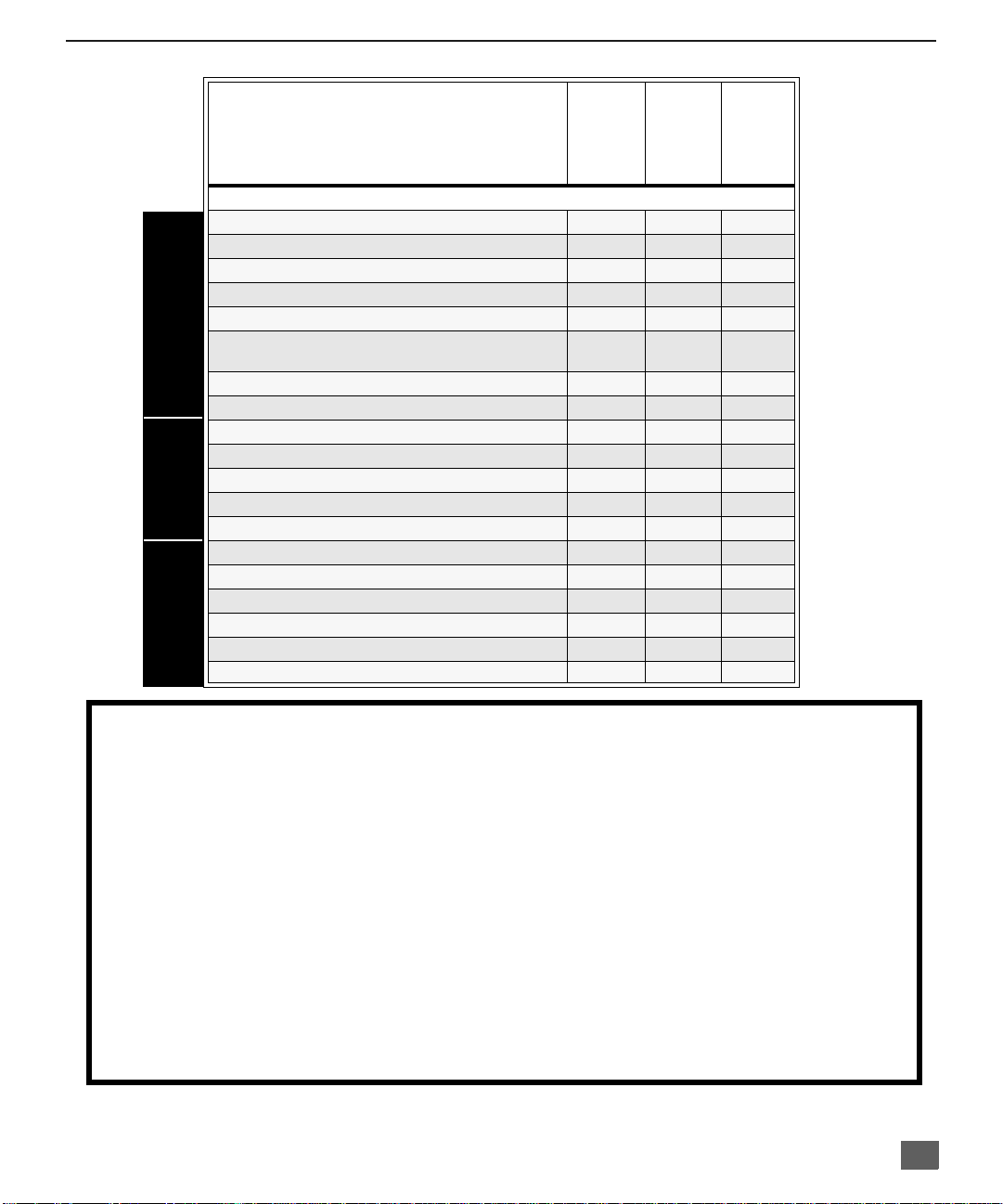
Feature Chart
F
EATURE CHART
PT-51HX41
PT-56HX41
PT-61HX41
FEATURES
SPECIAL
MENU LANGUAGE ENG/SPAN/FR
2 TUNER SPLIT
VIDEO INPUT SKIP
CLOSED CAPTIONING
V-CHIP CAPABILITY
DIGITAL SCAN RATE
FEATURES
NTSC LINE - DOUBLER
VIDEO NORM
AUDIO NORM
STEREO
AI SOUND
BASS/BALANCE/TREBLE
SURROUND
DOLBY CENTER CHANNEL IN
A/V PROGRAM OUT
r r r
r r r
r r r
r r r
r r r
1080i,
480p
480p 480p 480p
r r r
r r r
r r r
r r r
r r r
r r r
r r r
r r r
1080i,
480p
1080i,
480p
A/V IN (REAR/FRONT) 4 (3/1) 4 (3/1) 4 (3/1)
A/V JACKS AUDIO
AUDIO OUT
S-VHS INPUT (REAR/FRONT)
COMPONENT INPUT
r r r
2/1 2/1 2/1
2 2 2
IMPORTANT INFORMATION REGARDING THE USE OF VIDEO GAMES, COMPUTERS, OR
OTHER FIXED IMAGE DISPLAYS.
WARNING: The marking or retained image on the picture tube resulting from viewing fixed
image is not an operating defect and as such is not covered by Warranty.
The projection television is designed to display constantly moving images on the screen.
Continuous viewing of stationary images such as letterbox pictures on standard screen TVs (wit h
top/bottom bars), n on-expanded s tandard (4:3) pictures on wide screen T Vs (with side bars shown
on each side o f an image), stock mark et report bars (ticker run ning at the bottom of the screen),
video game patterns, fixed scoreboards, bright station logos, on-line (internet) or repetitive computer
style patterns should be limited.
The extended use o f fixed image program material can cause a per manent picture tube dam age,
shown as a “shado w image” viewable on normal pr ograms. This type of irreversibl e picture tube
deterioration can be limited by performing the following steps:
• Limit the display of fixed image program material to no more than 15% of total viewing time per week.
• Turn the power off when not in use.
3

C
ONGRATULATIONS
Congratulations
Your new Projection Television (PTV) features state-of-the-art technology for high
quality picture and sound with complete audio/video connections for your home
theater system. Your PTV is designed to give you many years of enjoyme nt. It was
thoroughly tested and tuned at the factory for best performance.
Customer Record
The model and serial number of this product are located on the back of the PTV. You
should note the model and serial number in the space provided and retain as a permanent
record of your purchase. This will aid in identification in the event of theft or loss. Product
registration for U.S. customers is available at: www.prodreg.com/panasonic.
Care and Cleaning
Projection Screen (Turn PTV Off)
The projection scr een is a high precision l ens system wh ich has a p rotective scr een.
The protective screen is fully washable with the following precautions:
r Use a mild soap solution or window cleaner and a clean cloth.
r Avoid excessive moisture and wipe dry.
r Avoid bumping or scraping the screen.
Cabinet and Remote Control
r For cabinets and remote control, use a soft c loth dampened with water or a mild
r Do not use benzene, thinner or other petroleum based products.
Model
Number
Serial
Number
• DO NOT USE ABRASIVE CLEANERS.
• Do not use laundry detergent or automatic dishwasher soap.
• Do not use alcohol, ammonia, or petroleum based products.
• Prevent solution from running into the receiver below.
detergent solution. Avoid excessive moisture and wipe dry.
Specifications
4
Power Source
Channel Capability - 181 VHF-12; UHF-56; Cable-113
Component Input (Y / PB / PR)
PT-51HX41(4.2A)
PT-56HX41(4.2A)
PT-61HX41(4.2A)
Video Input Jacks 1Vp-p, 75 Ohm, Phono Jack Type
Audio Input Jacks 500mV RMS 47K Ohm
Video Output Jack 1Vp-p, 75 Ohm, Phono Jack Type
Audio Output Jacks 0-2.0V RMS 4.7K Ohm
S-Video Input Jacks S-Video (Y -C) Connector
120V AC, 60Hz
75 Ohm, Phono Jack Type
Specifications are subject to change without notice or obligation.
Installation
Television Location
This unit can be used as an entertainment center. Consult your dealer for available options.
r Avoid excessive sunlight or bright lights, including reflections.
r Keep away from excessive heat or moisture. Inadequate ventilation may cause internal
component failure.
r Fluorescent lighting may reduce remote control transmitting range.
r Keep away from magnetic equipment, including motors, fans and external speakers.
Optional Cable Connections
Shielded audio and video cables should be used between components. For best results:
r Use 75-ohm coaxial shielded cables.
r Use appropriate input and output connectors, that match your component connectors.
r Avoid long cables to minimize interference.
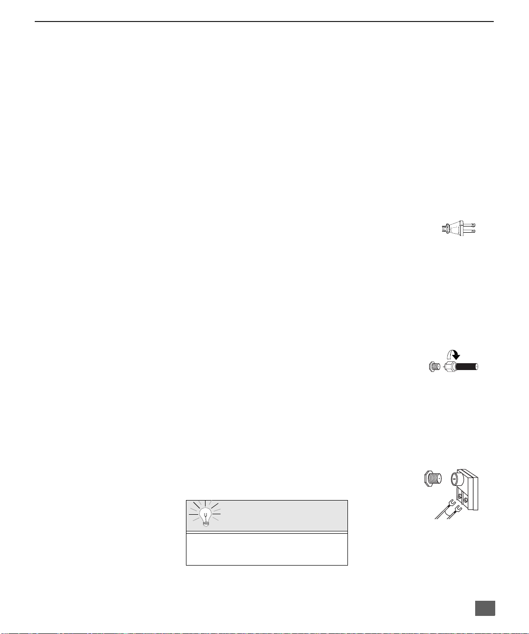
AC Power Supply Cord
CAUTION: TO PREVENT ELECTRIC SHOCK, MATCH WIDE BLADE OF PLUG TO
WIDE SLOT OF AC OUTLET AND FULLY INSERT. DO NOT USE A PLUG WITH A
RECEPTACLE OR OTHER OUTLET UNLESS THE BLADE CAN BE FULLY
INSERTED TO PREVENT BLADE EXPOSURE.
PROTECT POWER CORDS FROM BEING WALKED ON, ROLLED OVER, CRIMPED, BENT, OR
PINCHED, PARTICULARLY AT PLUGS, CONVENIENCE RECEPTACLES, AND THE POINT WHERE
THEY EXIT FROM THE APPARATUS.
Cable / Antenna Connection
For proper reception, either a cable or antenna connection is required.
Cable Connection
Connect the cable supplied by your local cable company to ANT1
connection on back of tele visio n. Sele ct cab le mod e and AN T1 in SET UP
menu under Prog Chan (Program Channels).
Note: A cable converter box may be required for proper reception.
Check with your local cable company for compatibility
requirements.
I
NSTALLATION
Polarized plug
Incoming Cabl e from
Cable Company
75 Ohm VHF/UHF
on back of PTV
Antenna Connections
• For proper reception of VHF/UHF channels, an external antenna is required. For
best reception, an outdoor antenna is recommended.
• Connect home antenna to ANT1 connection on back of
television. Select TV mode and ANT1 in the SET UP menu
under Prog Chan.
Cable Mode is preset at the factory.
Antenna users must change to TV Mode and
ANT 1 in the Set Up menu.
Incoming Cable from
Home Antenna
Cable Preset
5
I
NSTALLATION
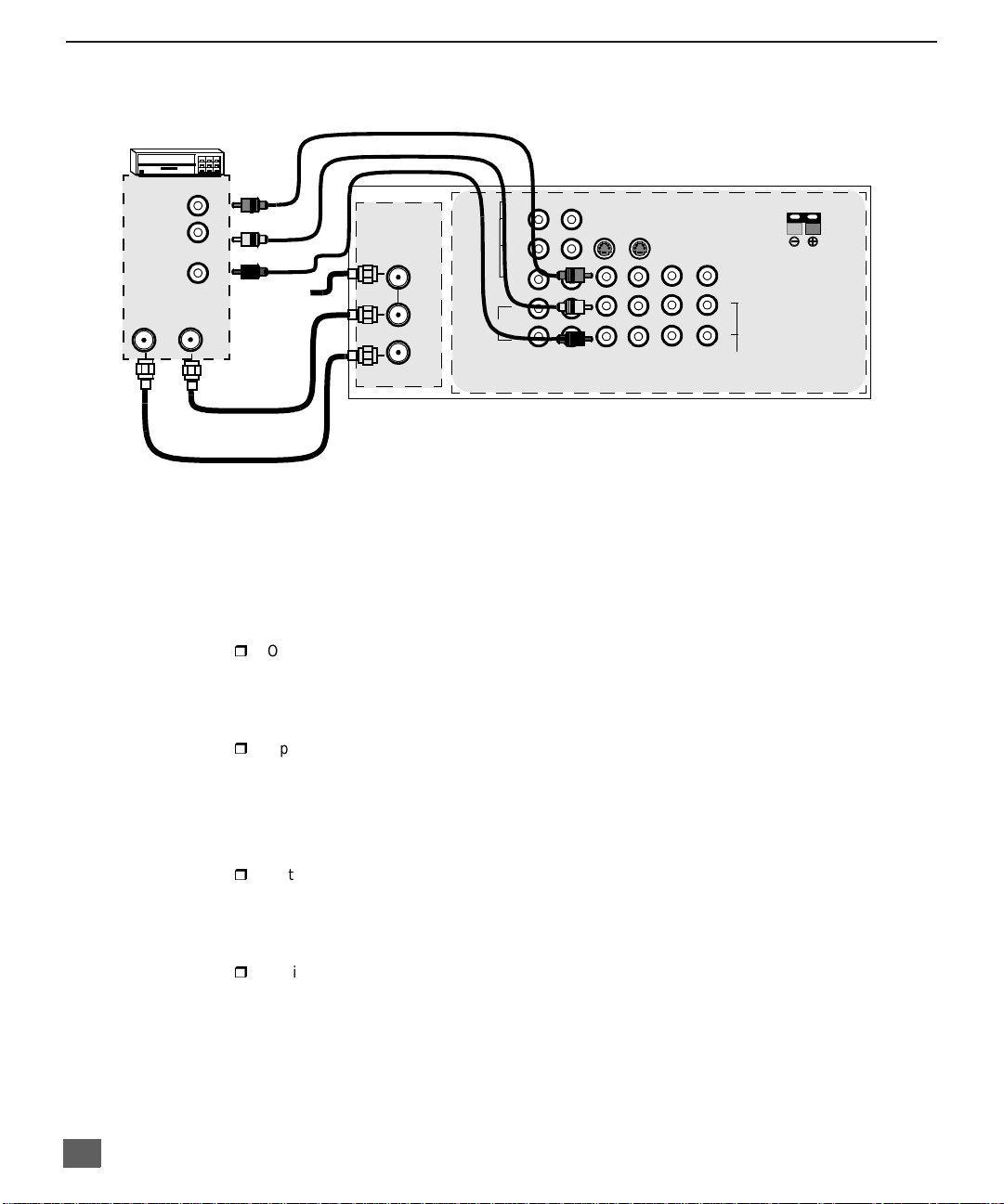
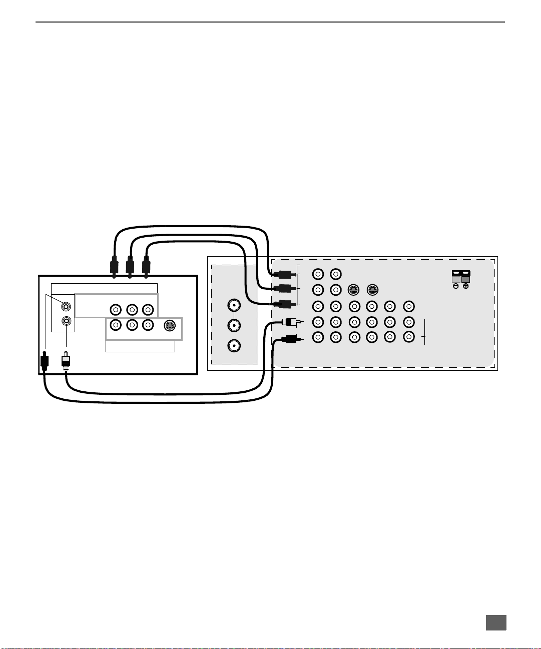
Optional Equipment Connections
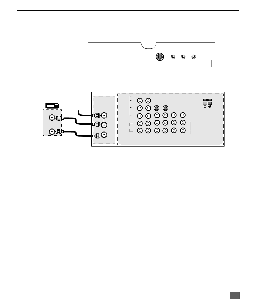
VCR Connection
Follow this diagram when connecting your television to a VCR only.
VCR
VIDEO OUT
L
AUDIO OUT
ANT INANT OUT
R
Incoming
Cable
Note: The remote cont rol must be programmed with supplied c odes to operate the VCR. See
Programming the Remote Control in the Remote Control Quick Reference Guide.
Viewing a television program
Procedure
1. Select ANT1 in the SET UP menu under Prog Chan (Program Channels).
2. Tune the television to the television program you want to vi ew.
Viewing a video
Procedure
r
Option A
1. Select ANT1 in the SET UP menu under Prog Chan (Program Channels).
2. Press the TV/VIDEO button on the remote control to select the video input (VIDEO 1,
VIDEO 2, etc.) connecte d to your VCR.
3. Begin the vide o.
r
Option B
1. Select ANT2 in the SET UP menu under Prog Chan (Program Channels).
2. Tune the television to Ch annel 3 or 4, depending on your VC R .
3. Begin the vide o.
Recording a television program
Procedure
r
Option A (Recording and viewing the same program)
1. Select ANT2 in the SET UP menu under Prog Chan (Program Channels).
2. Tune the television to Ch annel 3 or 4, depending on your VC R .
3. Using the VCR, tu ne to t he t el ev is io n pr ogram you want to record.
4. Begin recording.
r
Option B (Recording one pr ogram while viewing another program)
1. Select ANT1 in the SET UP menu under Prog Chan (Program Channels).
2. Press the TV/VIDEO button on the remote control to select the video input (VIDEO 1,
VIDEO 2, etc.) connecte d to your VCR.
3. Using the VCR, tu ne to t he t el ev is io n pr ogram you want to record.
4. Begin recording.
5. Press the TV/VIDEO button on the remote control to switch back to TV mode.
6. Tune the television to the television program you want to vi ew.
ANT 1
SPLIT OUT
ANT 2
CABLES NOT SUPPLIED
AUDIO
VIDEO
Y
P
B
P
R
L
R
12
COMPONENT
VIDEO INPUTS
CONNECTIONS ON BACK OF TV
12 50 WATTS (DIN) MAX.Ω
SVIDEO
INPUT 1INPUT 2INPUT
3
PROG
OUT
AMP
VIDEO
L
R
TO
AUDIO
CENTER
CHANNEL
INPUT
6
Optional Equipment Connections (Cont.)
Open the door on the PTV front panel to use the connections for your optional
equipment (Palmc order, VCR, or other video compon ents). Select input 4 mode by
pressing TV/VIDEO button.
CONNECTIONS OF FRONT OF PTV
Cable Box Connection
Follow this diagram when connecting your television to a cable box only.
INPUT 4
S -VIDEO VIDEO L-AUDIO-R
CONNECTIONS ON BACK OF TV
I
NSTALLATION
CABLE BOX
ANT IN
ANT OUT
INCOMING
CABLE
CABLES NOT SUPPLIED
Note: The remote control must be programmed with supplied codes to operate the cable
box. See Programming the Remote Control in the Remote Control Quick Reference
Guide.
Viewing a premium (scrambled) cable channel
Procedure
1. Select ANT2 in the SET UP menu under Prog Chan (Program C hannels).
2. Tune the television to Channel 3.
3. Using the cable box, tune to the premium cable channel you want to view.
Note: To use special features suc h as Fav orite Cha nnels and Ch annel Ca ptions (see Spec ial
Features section for more information), ANT1 must be selected in the SET UP menu
under Prog Chan.
ANT 1
SPLIT OUT
ANT 2
AUDIO
VIDEO
Y
P
B
P
R
L
R
12
COMPONENT
VIDEO INPUTS
SVIDEO
INPUT 1INPUT 2INPUT
3
PROG
OUT
AMP
12 50 WATTS (DIN) MAX.Ω
VIDEO
L
R
TO
AUDIO
CENTER
CHANNEL
INPUT
7
I
NSTALLATION
Optional Equipment Connections (Cont.)
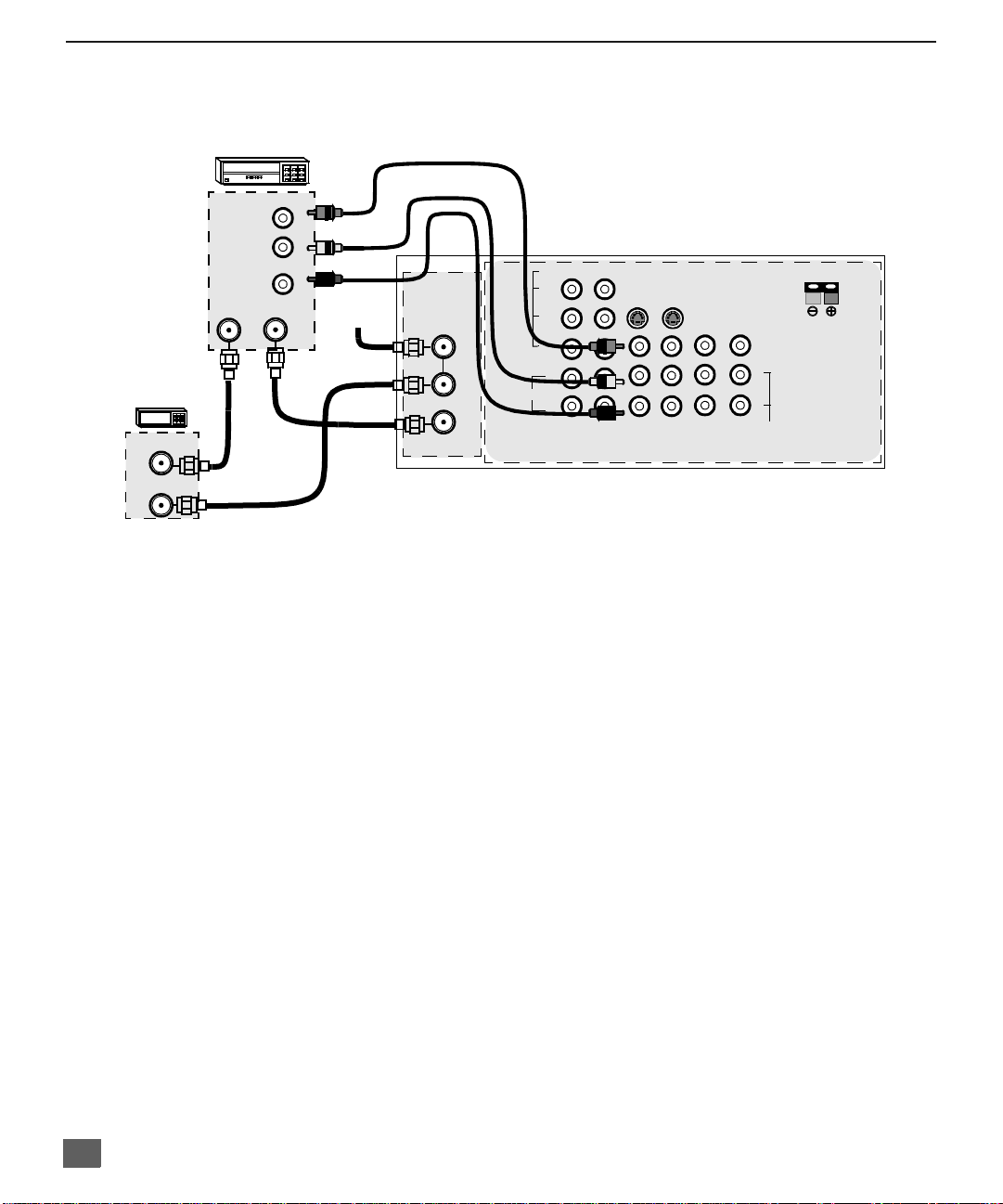
VCR and Cable Box Connection
Follow this diagram when connecting your television to both a VCR and a cable box.
VCR
VIDEO OUT
CABLE BOX
ANT OUT
ANT IN
CONNECTIONS ON BACK OF TV
VIDEO
Y
P
B
P
R
L
AUDIO
R
12
COMPONENT
VIDEO INPUTS
INPUT 1INPUT 2INPUT
SVIDEO
3
PROG
OUT
AMP
12 50 WATTS (DIN) MAX.Ω
VIDEO
L
R
TO
AUDIO
CENTER
CHANNEL
INPUT
AUDIO OUT
ANT OUTANT IN
L
R
Incoming
Cable
ANT 1
SPLIT OUT
ANT 2
CABLES NOT SUPPLIED
Note: The remote control must be programmed with supplied codes to operate the VCR and
cable box. See Programming the Remote Control in the Remote Control Quick
Reference Guide.
Viewing a premium (scrambled) cable channel
Procedure
1. Select ANT2 in the SET UP menu under Prog Chan (Program C hannels).
2. Tune the television to Channel 3.
3. Using the cable box, tune to the premium cable channel you want to view.
Note: To use special features suc h as Fav orite Cha nnels and Ch annel Ca ptions (see Spec ial
Features section for more information), ANT1 must be selected in the SET UP menu
under Prog Chan.
Recording a premium (scrambled) cable channel
Procedure
1. Select ANT2 in the SET UP menu under Prog Chan.
2. Press the TV/VIDEO button on the remote control to select the video input ( VIDEO 1,
VIDEO 2, etc.) connected to your VCR.
3. Turn the VCR ON.
4. Tune the VCR to Channel 3 or 4, depending on your VCR.
5. Using your cable box, tune to the premium cable channel you want to record.
6. Begin recording.
Note: To view a different channel while recording:
• Select ANT1 in the SET UP menu under Prog Chan.
• Press the TV/VIDEO button on the remote control to select TV mode.
• Tune the television to a television program (except another premium cable channel).
8
Optional Equipment Connections (Cont.)
Amplifier Connection (TO AUDIO AMP)
To listen through a sep arate s tereo s ystem, c onnec t an exter nal aud io am plifie r T O AUDIO AMP
outputs on back of television.
Note: TO AUDIO AMP terminals cannot be connected directly to external speakers.
Audio Adjustments
1. Select SPEAKERS ON located in the on screen AUDIO menu .
2. Set amplifier volume to minimum.
3. Adjust PTV volume to desired level.
4. Adjust amplifier volume to match the PTV.
5. Select SPEAKERS OFF & VARIABLE AUDIO OUT from AUDIO menu to control
speakers from the PTV or select FIXED AUDIO OUT to control speakers from the
external amplifier.
6. Volume, mute, bass, treble and balance are now controlled from the PTV, if you select
V ARIABLE AUDIO OUT mode.
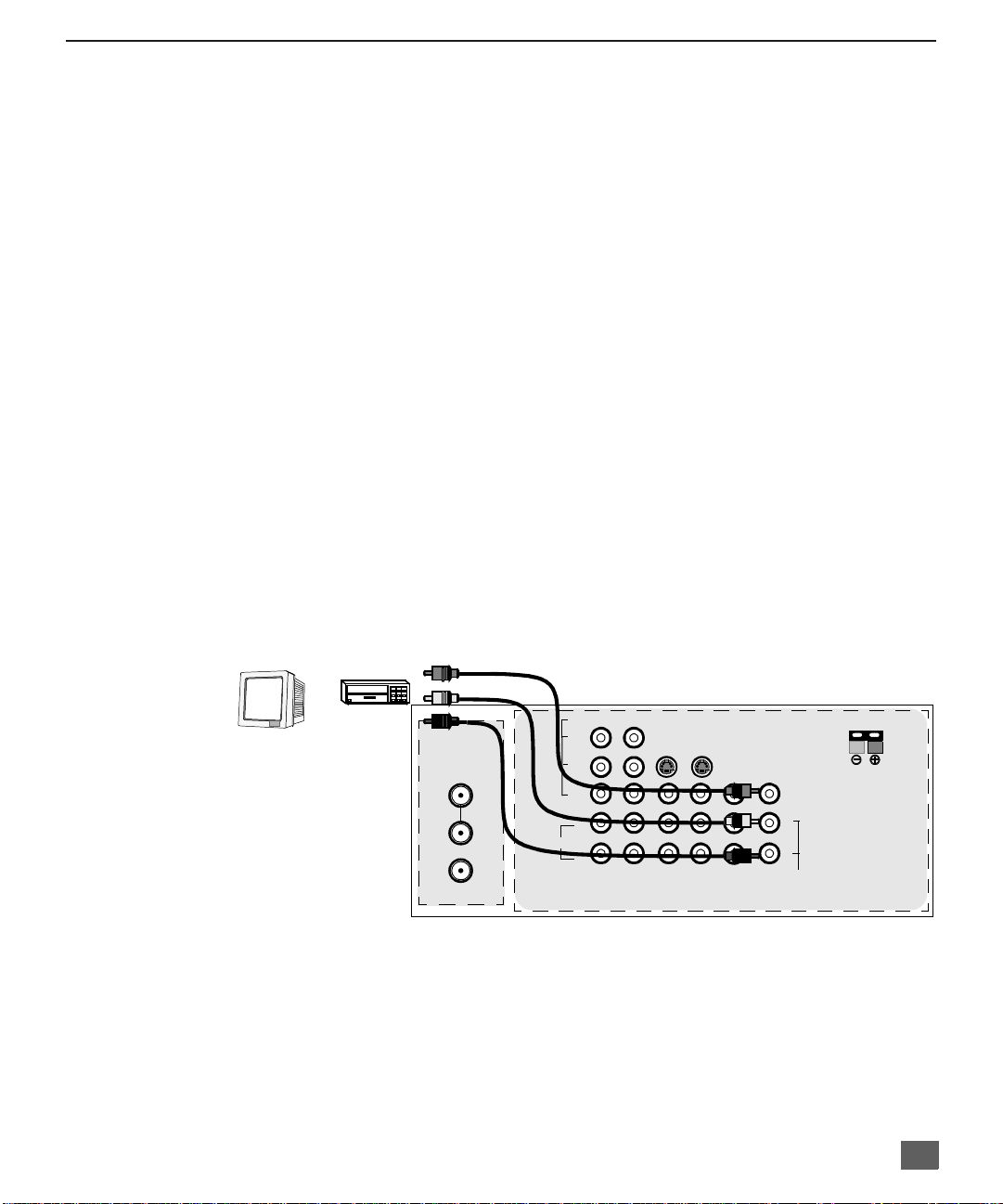
Program Out Connection (PROG. OUT)
To use the PTV audio and video with optional video equipment, use PROG. OUT and TO
AUDIO AMP terminals on the back of the PTV.
Procedure
1. Connect optional video equipment to PROG. OUT video and TO AUDIO AMP R/L
Audio terminals.
2. PROG OUT terminal display is the same as the on screen display.
See optional equipment manual for further instructions for recording or monitoring.
I
NSTALLATION
MONITOR
CABLES NOT SUPPLIED
VCR
OR
ANT 1
SPLIT OUT
ANT 2
CONNECTIONS ON BACK OF TV
VIDEO
Y
P
P
AUDIO
B
R
L
R
12
COMPONENT
VIDEO INPUTS
INPUT 1INPUT 2INPUT
SVIDEO
12 50 WATTS (DIN) MAX.Ω
CENTER
TO
AUDIO
CHANNEL
INPUT
VIDEO
L
R
PROG
3
OUT
AMP
9
D
OLBY CENTER CHANNEL INPUT CONNECTION
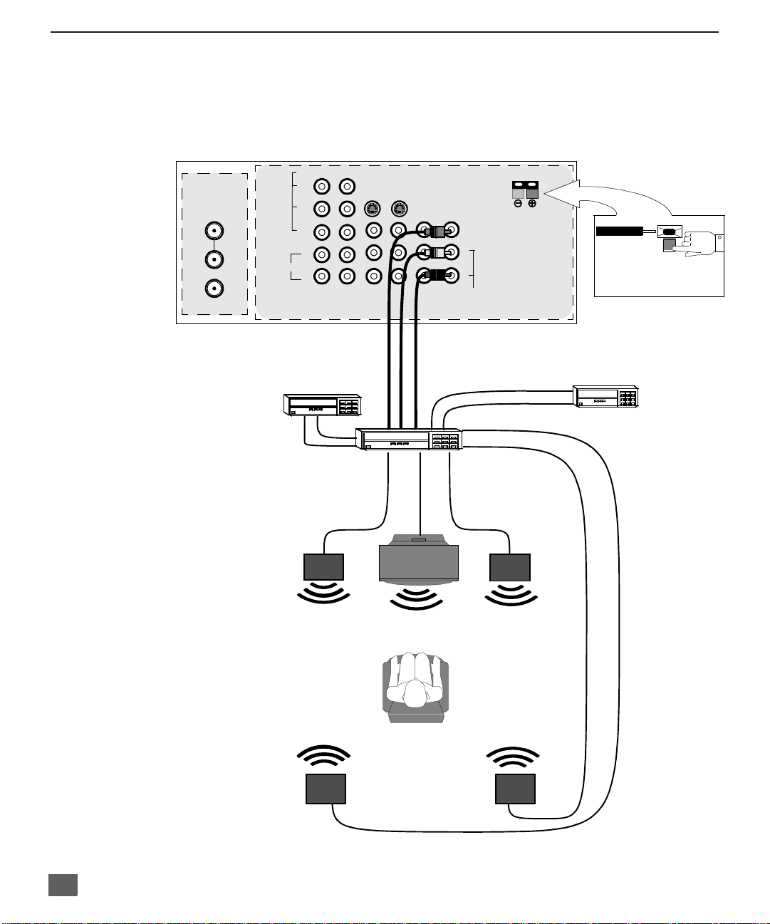
Dolby Center Channel Input Connection
Your PTV can be configured to use the PTV speakers as center channel speakers in
Dolby* surround sound transmissio n. Conne ct a Dolby surroun d amplifi er to CENT ER
CHANNEL INPUT on the back of the PTV as sho wn. DOLBY CENTER MODE & FIXED
AUDIO OUT must be selected in the AUDIO Roller Guide
™** menu under SPEAKERS.
TERMINALS ON BACK OF PTV
ANT 1
SPLIT OUT
ANT 2
CENTER CHANNEL INPUT
(1) Push and hold down button.
(2) Insert bare wire into terminal
and release button.
Video Component
CONNECTIONS ON BACK OF TV
CENTER CHANNEL INPUT
VIDEO
12 Ohms 50W (DIN) MAX
Y
P
B
P
R
L
AUDIO
ANT 2
R
12
COMPONENT
VIDEO INPUTS
SPLIT
OUT
ANT 1
INPUT 1INPUT 2INPUT
Video Compon ent
PTV
COMPONENT VIDEO INPUT
12 50 WATTS (DIN) MAX.Ω
S-
RL
VIDEO
VIDEO
AUDIO
L
R-AUDIO-L
R
PROG
OUT
AMP
RL
TO
AUDIO
PROG.
OUT
3
TO AUDIO AMP
Dolby Surround
AMPLIFIER
Channel Output
From Center
Channel Output
PTV
1
2
PRPBY
CENTER
CHANNEL
INPUT
VIDEO
S-VIDEOVIDEO
INPUT 1
INPUT 2
INPUT 3
Dolby Surround
AMPLIFIER
From Center
CENTER CHANNEL INPUT
(1) Push and hold down button.
(2) Insert bare wire into terminal
and release button.
VCR
VCR
Left Front
Speaker
Left Front
Speaker
PTV Speakers
Center Channel
Left Rear
Surround Speaker
Left Rear
Surround Speaker
*”Dolby” and “Pro-logic” are the trademarks of Dolby Laboratories Licensing Corporation.
**U.S. Patent Pending
10
PTV Speakers
Right Front
Center Channel
Right Rear
Surround Speaker
Right Front
Speaker
Speaker
Right Rear
Surround Speaker
Picture In Picture (PIP) Operation
This television includes a two tuner Picture In Picture (PIP) feature. This allows
watching two (2) live broadcasts at the same tim e without or with an exte rnal video
source (VCR).
Basic PIP Operation
Procedure
Press the PIP button on the remote control to display the
Note: The audio is for the Main Picture only.
1. Choose channels for the
down buttons.
2. Choose channels for the
buttons or by using the numeric keypad.
The SWAP button switches the PIP and Main
Picture source. Press the RECALL button for
onscreen PIP and Main Picture source status.
PIP Operation with a Cable Box
Procedure
r To view premium (scrambled) cable channels through your cable box in the
Note: Use this procedure if you want to watch premium cable channels in the Main Picture while
viewing a television program or video in the PIP frame.
1. Select ANT2 in the SET UP menu under Prog Chan (Program C hannels).
2. Tune television to Channel 3.
3. Press the PIP button on the remote control to display the
Note: The audio is for the Main Picture only.
4. Verify the cable box is ON.
5. Choose channels for the
6. Choose channels for the
and using the PIP CHANNEL up/down buttons.
P
ICTURE IN PICTURE
PIP
frame onscreen.
PIP
frame by pressing the remote control PIP CHANNEL up/
Main Picture
by pressing the remote control CH up/down
(PIP) O
PERATION
SWAP Button
Main Picture
PIP
frame onscreen.
Main Picture
PIP frame
by tuning the cable box.
by pressing the TV button on the remote control
:
Note: Swap is not available when using the cable box to tune channels. If your cable box has a video
output, it can be connected to the television to allow you to use all PIP functions. See the
equipment manual for more information. (Tune the PIP to the video input connected to the cable
box).
11
S
PLIT SCREEN OPERATION
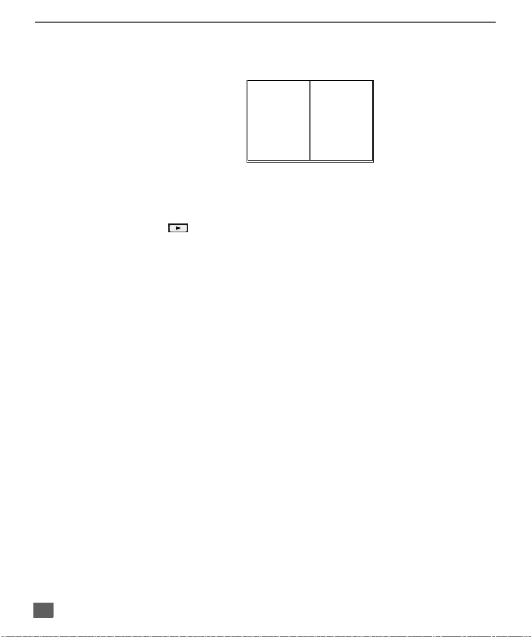
Split Screen Operation
This feature lets you watch two different channels side by side with or without an external video
source. The audio is from the Main picture only (left side).
Basic SPLIT Operation
Procedure
SPLIT/SIZE
Press the button on the remote control to display the
Note: The audio is from the Main Picture only.
1. Choose channels for the
2. Choose channels for the
3. The SWAP button switches the SPLIT and MAIN Picture source. Press RECALL
PLAY
up/down buttons.
buttons or by using the numeric keypad.
button for onscreen SPLIT and Main Picture source status.
MAIN SPLIT
SPLIT Picture
Main Picture
by pressing the remote control PIP CHANNEL
by pressing the remote control CH up/down
SPLIT
screen.
12
D
IGITAL
TV - SET-TOP BOX (DTV-STB) OR DVD C
Digital TV - Set-Top Box (DTV-STB) or DVD Connection
This television i s capable of displa ying 108 0i and 4 80p DTV s ignals when co nnected
to a DTV Tuner set-top-bo x (STB ). In orde r to v iew DT V pro gramm ing, the STB mus t
be connected to the component video inputs (Y, P
signal must be avail able in your are a. Select the o utput of the S TB to either 10 80i or
480p.
This television also utilizes a progressive scan doubler, which de-interlaces the NTSC
signal and progress ively scans the im age. This allows you to sit very close to the TV
and not see the thin black horizontal lines (venetian blind effect) associated with
interlaced TV pictures.
Use this diagram to connect the Panasonic DTV-STB (Digital TV-Set-Top Box) or DVD
to the back of your PTV.
TERMINALS ON BACK OF DTV-STB OR DVD PLAYER
DIGITAL TV OUTPUT
MAIN
VIDEO
L-AUDIO-R
Y
R-AUDIO-L
P
RPB
-VIDEO
NTSC OUTPUT
S-VIDEO
ANT 1
SPLIT OUT
ANT 2
CONPONENT INPUT TERMINALS ON BACK OF TV
VIDEO
Y
P
B
P
R
L
AUDIO
R
12
COMPONENT
VIDEO INPUTS
, PR) of the television. A DTV
B
SVIDEO
INPUT 1INPUT 2INPUT
3
PROG
OUT
AMP
12 50 WATTS (DIN) MAX.Ω
VIDEO
L
R
TO
AUDIO
ONNECTION
CENTER
CHANNEL
INPUT
CABLES NOT SUPPLIED
Note: There are 2 sets of three video inputs, Y, PB, and PR. Separate component color
inputs provi de luminance and color separation. Use the L (left) a nd R (right) audio
inputs.
13
R
OLLER GUIDE MENU NAVIGATION
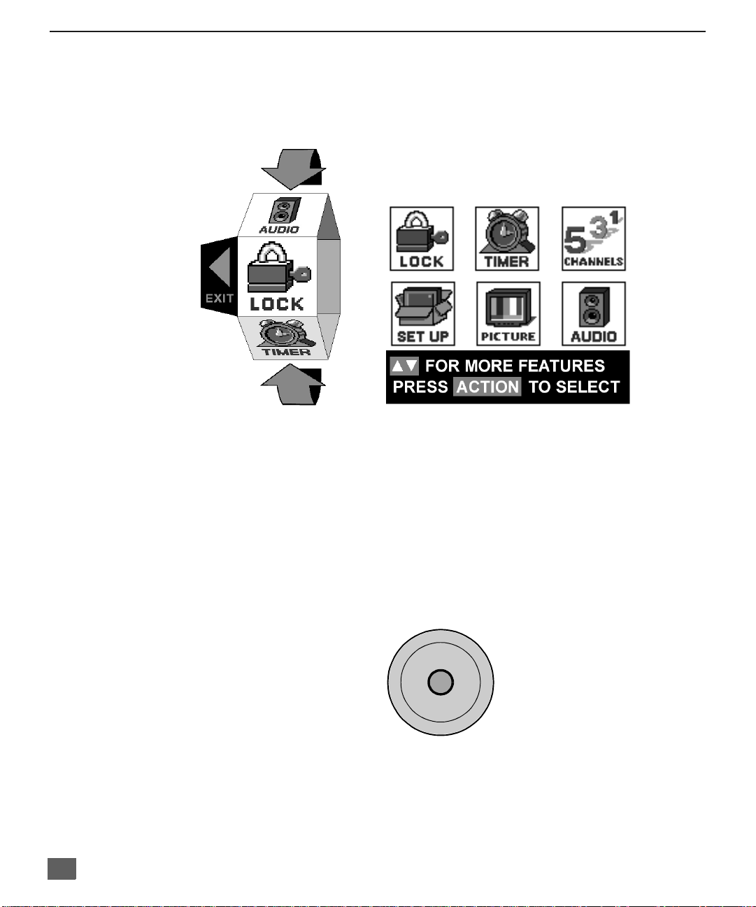
Roller Guide Menu Navigation
Procedure
1. Press the ACTION button on the Remote Control to display the Roller Guide Menu.
2. Press the CH up/down to rotate the Roller Guide to the desired feature.
3. Press the ACTION button to display main menus and submenus.
4. Press the CH up/down buttons to highlight desired main menu feature.
5. Press the VOL right button to enter submenus.
6. Press the CH up/down buttons to highlight desired submenu feature.
7. Press the VOL right/left button to select or adjust feature.
8. Press the ACTION button twice to return to the Roller Guide Menu.
9. To exit the Roller Guide Menu, press the VOL left button.
ROLLER GUIDE MENU SELECTIONS
Remote Control Guide
The Re mote Control Quick Reference Guide is located within the package provided
with this PT V.
14
Remote ACTION / Navigation Button
p
CH
ACTION
VOL VOL
tu
CH
q
R
OLLER GUIDE FEATURE CHART
Roller Guide Feature Chart
M
ENU
D
ESCRIPTION
SET UP
LANGUAGES
PROG. CHAN
(Program Channels)
CC
(Closed Captioning)
OTHER ADJ.
r Select English, Spanish, or French menu.
r MODE - Select Cable or TV. See
Installation section in manual.
r ANTENNA - Select ANT 1 or ANT 2.
r AUTO PROGRAM - Automatically program
channels having a signal into memory.
r MANUAL PROGRAM - Manually add or
delete channels from memory.
r CC ON MUTE - Activate C1-C4 for Closed
Captioning display when the remote MUTE
button is p ressed.
r CC MODE - Select T1-T4 or C1-C4 for
Closed Captioning, program guides and
other information.
r AUTO POWER ON - Select SET to power
up the TV at the same time as the Cable
Box or other components or select OFF.
r CONVERGENCE 1 - Adjustment may be
required w hen the PTV i s moved bec ause
of the effects of the Earth’s magnetic field
on the projection tubes.
r CONVERGENCE 2 - Adjustment may be
required after setting Convergence 1.
AUDIO ADJ.
(Adjustments)
AUDIO
r MODE - Select STEREO, SAP (Second
Audio Program) or MONO. (Use MONO
when stereo signal is weak.)
r BASS - Increase or decrease the bass
response.
r TREBLE - Increase or decrease the treble
response.
r BALANCE - Emphasize the left/right
speaker volume.
r NORMAL - Reset BASS, TREBLE and
BALANCE to factory default.
15
R
OLLER GUIDE FEATURE CHART
Roller Guide Feature Chart (Cont.)
M
ENU
OTHER ADJ.
(Adjustments)
r AI SOUND - Automatically adjust volume
to maintain a comfortable listening level.
(AI sound is not available in VIDEO mode).
r BBE - Sound technology enhances speech
intelligibility and restores the dynamic
range of musical passages to provide
outstanding natural sound.
D
ESCRIPTION
SURROUND
SPEAKERS
CLOCK SET
SLEEP
TIMER 1
TIMER 2
r MODE - Enhances audio response when
listening to stereo.
r ON - PTV speakers operate normally.
r OFF & VARIABLE AUDIO OUT -
PTV speakers off - audio adjustable by
PTV.
r OFF & FIXED AUDIO OUT -
PTV speakers off — audio adjustable only
by the external amplifier.
r DOLBY CENTER MODE & FIXED AUDIO
OUT - PTV speakers provide center
speakers for Dolby sound transmission
available on video or laser disc. (See
Installation section in manual.)
TIMER
r Set the time and the day of the week.
(Time will display onscreen after turning on
the television, pressing the RECALL button
or changing channels).
r Set timer to turn off PTV in 30, 60 or
90 minutes. Select NO to turn timer off.
r Set one or both timers to automatically turn
television on and off at selected times, on
selected c hannels, and on selected days.
(Clock must be set to use Timer features).
16
R
OLLER GUIDE FEATURE CHART
Roller Guide Feature Chart (Cont.)
M
ENU
VIDEO ADJ1
(Adjustments)
VIDEO ADJ2
(Adjustments)
OTHER ADJ
(Adjustments)
r COLOR - Adjust desired color intensity.
r TINT - Adjust natural flesh tones.
r BRIGHTNESS - Adjust dark areas for crisp
detail.
r PICTURE - Adjust white areas of picture.
r SHARPNESS - Adjust clarity of outline
detail.
r NORMAL- Reset all picture adjustments to
factory default settings.
r COLOR TEMP NORMAL - Adjust white
balance to COOL (blue), WARM (red) or
NORMAL.
r NATURAL COLOR - Expands the color
reproduction range resulting in vivid
pictures with natural color gradation and
highly delicate hues.
r VIDEO NR - Reduces noise in the channel,
commonly called snow. Remains off when
receiving strong signal.
r 3D Y/C FILTER - Minimize noise and cross
color in the picture.
r ASPECT - Select 16:9 or 4:3 with 1080i
input signal from STB.
r SCAN MODE - Select TV mode (frame
doubling) for optimum detail and clarity.
Select Game mode (line doubling) to
optimize picture when playing complex,
fast action video games.
r COLOR MATRIX - Select HD or SD to
automatically adjust color parameters for
HD (high definition and SD (standard
definition) transmissions.
D
ESCRIPTION
PICTURE
17
 Loading...