

Panasonic PT-61G46, PT-51G46C Owner’s Manual
H
naSOnuC
Color
Operating Instructions
Projection5ysiiem
PT-51 G46
PT-51 G46C
Read these instructions completely before operating.
Contents subject to change without notice or obligation.
NO'I'E: The Cabinet Glass Doors Installation Instructions
are located in the back of this Manual.
Copyright 1997 by Matsushita Electric Corporation
of America. All rights reserved. Unauthorized
copying and distribution is aviolation of law.
PT-61G46
Printed in U.S.A.
-I-QB2AA0109-1
Safety Instructions
WARNING
WARNING: To reduce the risk of electric shock do not remove cover or back. No
user-serviceable parts inside. Refer servicing to qualified service personnel.
The lightning flash with The exclarnationpointwithin
that parts inside the product operating and servicing
__. arrow-head within a triangle A a triangle is intended to tell
Note to CATV System Installer: This reminder is provided to call the CATV system installer's attention to Article
820-40 of the NEC that provides guidelines for proper grounding and, in particular, specifies that the cable ground shall be
connected to the grounding system of the building, as close to the point of cable entry as I_ractical.
Safety Instructions for Television Receivers
1. Read and apply the operating instructions provided with your television receiver.
2. Read all of the instructions given here and retain them for later use.
3. Unplug this television receiver from the wall outlet before cleaning. Do not use liquid or ,aerosol cleaner,,;. Use a damp
cloth for cleaning.
4. Do not use attachments not recommended by the television receiver manufacturer as they may cause Iqazards.
5. Do not use this television receiver near water. For example: Avoid placing it near a bathtul:, washbowl, kitchen sink, or
laundry tub, in a wet basement, or near a swimming pool, etc.
6. Do not place this television receiver on an unstable cart, stand or table. The television receiver may fall, causing serious
injury to a child or adult, and serious damage to the appliance. Use only with a cart or stand recommended by the
manufacturer, or sold with the television receiver. Wall or shelf mounting should follow the manufacturer's instructions,
and shoulc_iuse a mounting kit approved by the manufacturer.
6A. An appliance and cart combination should be moved with care. Quick stops, excessive force, and
uneven surfaces may cause the appliance and cart combination to overturn.
7. Slots and openings in the cabinet and the back or bottom are provided for ventilation, and to insure
reliable operation of the television receiver and to protect it from overheating. These openings must not be blocked or
covered. The openings should never be blocked by placing the television receiver on a bed, sofa, rug or other similar
surface. This television receiver should never be placed near or over a radiator or heat register. This television receiver
should not be placed in a built-in installation such as a bookcase unless proper ventilation is provided.
8. Operate only from the type of power source indicated on the marking label. If you are not sure of the type of power
supplied to your home consult your television dealer or local power company. For television receivers designed to
operate from battery power, refer to the operating instructions.
9. This television receiver is equipped with a polarized alternating-current line plug (a plug having one blade wider than the
other). This plug will fit into the power outlet only one way. This is a safety feature. If yo_Jare unable to insert the plug
fully into the outlet, try reversing the plug. If _
the plug should still fail to fit, contact your '---"_-'-[_'-_
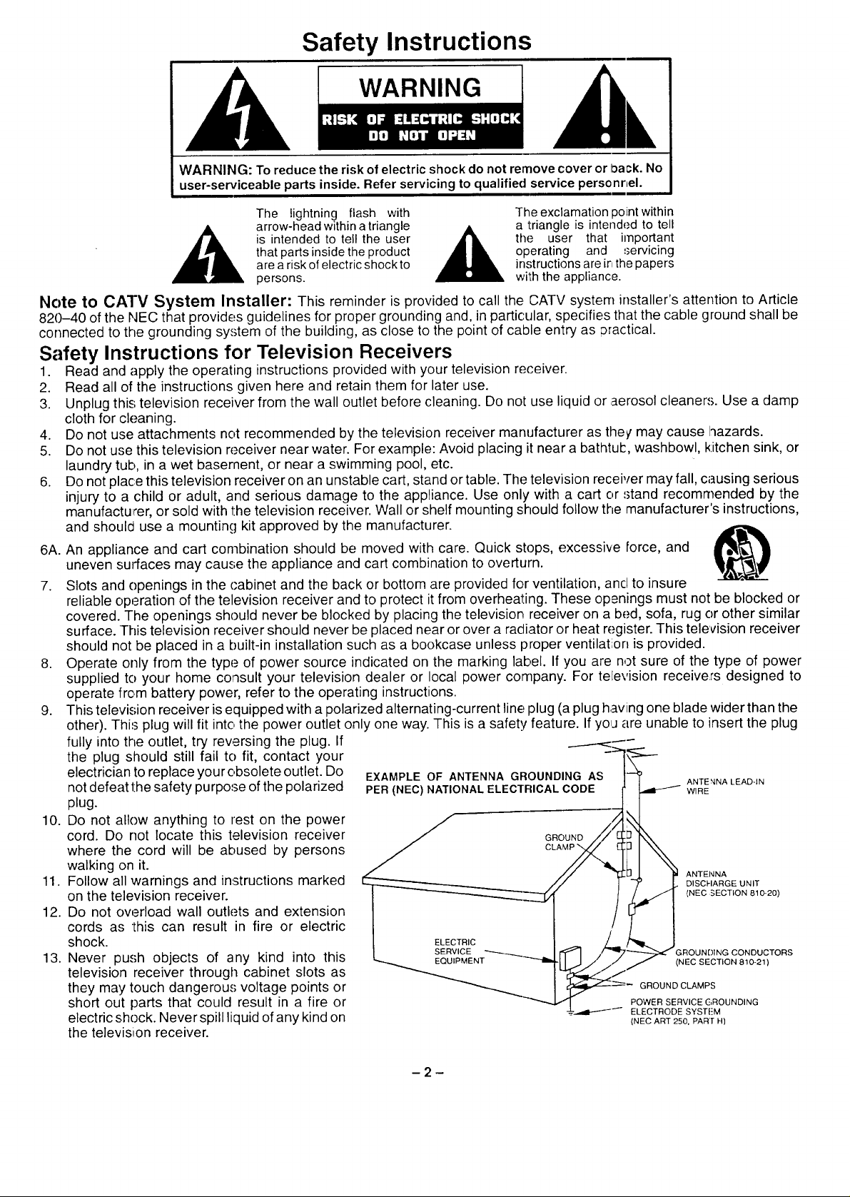
electrician to replace yourobsolete outlet. Do EXAMPLE OF ANTENNA GROUNDING AS t'_ ANTENNALEAD-IN
not defeat the safety purpose of the polarized PER(NEC)NATIONALELECTRICALCODE I'_ WIRE
plug.
10. Do not allow anything to rest on the power _ /
cord. Do not locate this television receiver _ GROUND/// C]_[_ "_
where the cord will be abused by persons cLAup _]
walking on it.
11. Follow all warnings and instructions marked / DISCHARGEUNIT
on the television receiver. CZ¢'1 (NEC SECTION 810-20)
12. Do not ow_=rloadwall outlets and extension
cords as this can result in fire or electric
shock.
13. Never push objects of any kind into this _ROUNr)INGCONDUCTORS
television receiver through cabinet slots as
they may touch dangerous voltage points or GROUNDCLAMPS
short out parts that could result in a fire or POWERSERVlCEGROUNDING
electric shock. Never spill liquid of any kind on {NECART250.PAR[H)
the televisi_on receiver.
are a risk of electric shock to instructions are ir_the papers
is intended to tell the user ,__ the user that important
persons, wi'Ih the appliance.
!
ELECTRODE SYSTFM
ANTENNA
(NEC SECTION 810-21)
-2-
14. Ifan outside antenna is connected to the television equipment, be sure the antenna system is grounded so as to provide
some protec'tion against voltage surges and built up static charges. In the U.S. Section ,310 of the National Electrical
Code and in Canada Part 1 of the Canadian Electrical Code provides information with respect to proper grounding of the
mast and supporting structure, grounding of the lead-in wire to an antenna discharge unit, size of grounding conductors,
location of antenna-discharge unit, connection to grounding electrodes, ancl requirements far the grounding electrode.
See Figure.
15. For added protection for this television receiver during a lightning storm, or when it is left urattended and unused for long
periods of tirne, unplug it from the wall outlet and disconnect the antenna. This will prevent damage to the receiver due to
lightning and power-line surges.
16. An outside antenna system should not be located in the vicinity of overhead power lines or 3ther electric light or power
circuits, or where it can fall !nto such power lines or circuits. When installing an outside antenna system extreme care
should be taken to keep from touching such power lines or circuits as contact with them might be fatal.
17. Unplug this television receiver from the wall outlet, and refer servicing to qualified service personnel unde rthe following
conditions:
a. When the power cord or plug is damaged or frayed.
b. If liquid has been spilled into the television receiver.
c. If the television receiver has been exposed to rain or water.
d. If the television receiver does not operate normally by following the operating instructions. Adjust only those controls
that are covered by the operating instructions as improper adjustment of other controls may result in damage and will
often require extensive work by a qualified technician to restore the television receiver to normal operation.
e. If the television receiver has been dropped or the cabinet has been damaged.
f. When the television receiver exhibits a distinct change in performance - this indicates a need for service.
18. Do not attempt to service this television receiver yourself as opening or removing covers m_Lyexpose you to dangerous
voltage or other hazards. Refer all servicing to qualified service personnel.
19. When replacement parts are required, be sure the service technician has used replacement parts specified by the
manufacturer that have the same characteristics as the original part. Unauthorized substitutions may result in fire,
electric shock, or other hazards.
20. Upon completion of any service or repairs to this television receiver, ask the service technician to perform routine safety
checks to determine that the television is in safe operating condition.
21. WARNING:: To prevent fire or shock hazard, do not expose this appliance to rain or moisture.
22. CAUTION: TO PREVENT ELECTRIC SHOCK DO NOT USE THIS (POLARIZED) PLUG WITH A RECEPTACLE OR
OTHER C)UTLET UNLESS THE BLADES CAN BE FULLY INSERTED TO PREVENT BLADE EXPOSLJRE.
Note: This equipment is designed to operate inthe U.S.A., Canada and other countries where tqe broadcastiqg system and
AC house current is exactly the same as in the U.S.A. and Canada.
Important Information Regarding Use of Video Games, Computers, DSS or Other Fixed Image Displays.
The extended Jse of fixed image program material can cause a permanent "shadow im_Lge"on the picture tube. This
bac'kground image is viewable on normal programs in the form of a stationary fixed image. ]his type of irreversible picture
tube deterioration can be limited by observing the following steps:
A. Reduce the brightness/contrast setting to a minimum viewing level.
B. Do not display the fixed image for extended periods of time.
C. Turn the power off when not in actual use.
Note: Any marking or retained image on the picture tube resulting from fixed image use is not considerecl an operating
defect and as such is not covered by Warranty. This product is not designed to display fixed image patterns for
extended periods of time.
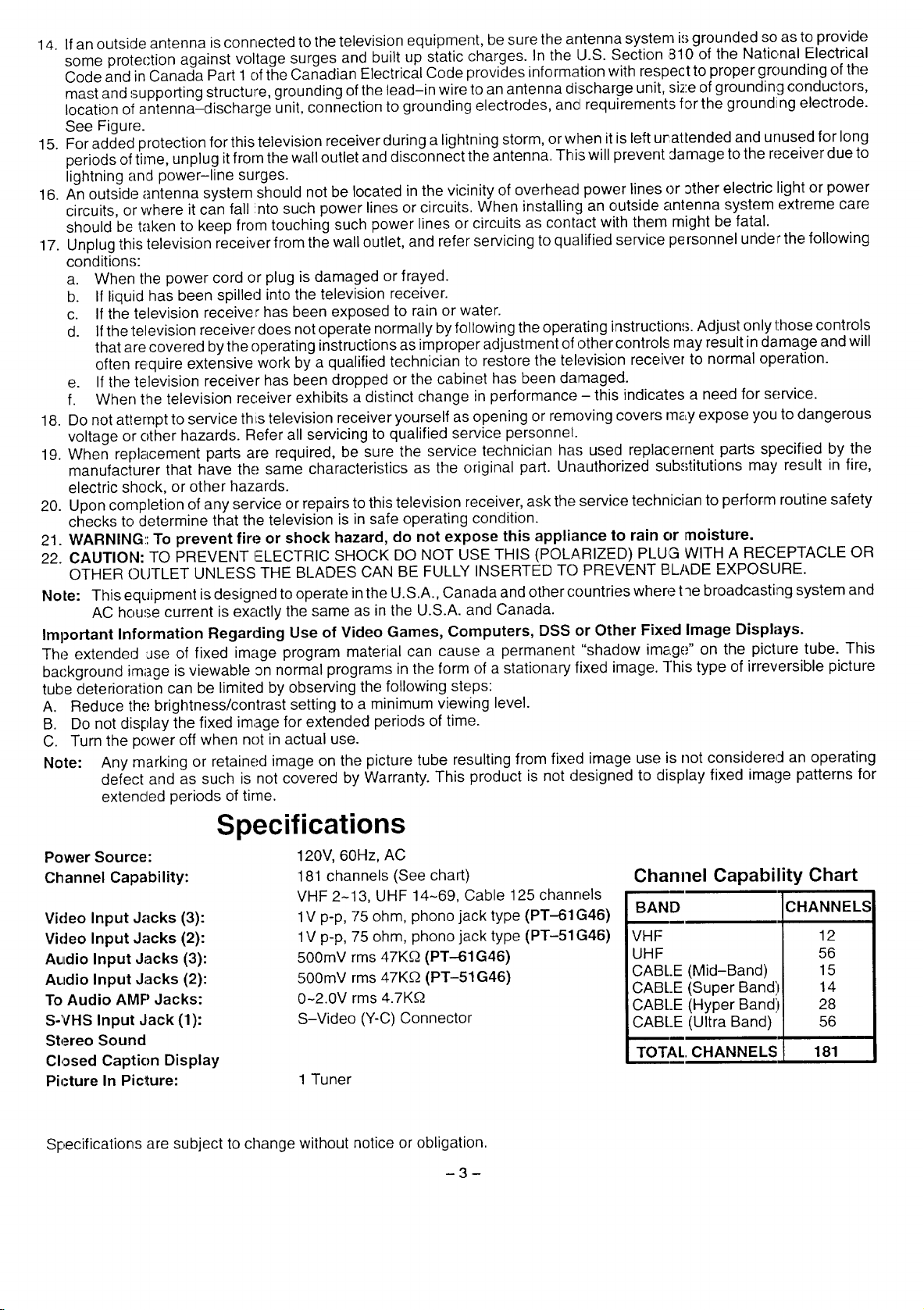
Specifications
Power Source:
Channel Capability:
Video Input Jacks (3):
Video Input Jacks (2):
A_ldio Input Jacks (3):
Audio Input Jacks (2):
To Audio AMP Jacks:
S-VHS Input Jack (1):
Stereo Sound
Closed Caption Display
Picture In Picture:
Specifications are subject to change without notice or obligation.
120V, 60Hz, AC
181 channels (See chart)
VHF 2-13, UHF 14-69, Cable 125 channels
lV p-p, 75 ohm, phono jack type (PT-61G46)
1V p-p, 75 ohm, phono jack type (PT-51G46)
500mV rms 47KD (PT-61G46)
500mV rms 47K£2 (PT-51G46)
0-2.0V rms 4.7K_
S-Video (Y-C) Connector
1 Tuner
3
Channel Capability Chart
BAND
UHF
CABLE (Mid-Band)
CABLE (Super Band'
CABLE (Hyper Band:
CABLE (Ultra Band)
TOTAL. CHANNELS 181
CHANNELS
12
56
15
14
28
56
Introduction
Congratulations on Your New Purchase
'Your new video component features an all solid state chassis which is designed to give you many years of enjoyment. It
was thoroughly tested and adjusted at the factory for best performance.
Inorder for you to take full advantage of your new video component, please read and follow the installation and operating
instructions supplied with this product.
Customer's Record
]-he model and serial number of this product may be found on its back cover. You should note the model and serial
number in the space provided and retain this book as a permanent record of your purchase: to aid in identification in the
event of theft or loss.
Ivlodel Number: Serial Number:
Care and Cleaning
Plastic Cabinets
'Wipe the cabinet with a soft cloth dampened with water or a mild detergent solution and wipe dry with asoft clean cloth.
.&void excessive moisture. Do not use benzene, thinners or other petroleum based cleaners.
Wood Cabinets
When dusting or polishing the cabinet, use a clean soft cloth and stroke straight with the grain. An occasional coat of
furniture polish will help preserve the finish. Do not use benzene, thinners or other petroleum based cleaners. Do not
place objects made of plastic or rubber directly on topof the cabinet. A chemical reaction coulcl result causing permanent
marring of the finish.
Remote Control Transmitter
Do not use benzene, thinners or other petroleum based cleaners to clean the Remote Control Transmitter. To clean,
wipe with a soft cloth slightly moistened with a mild detergent and then wipe dry with a soft clean cloth.
Screen Caution
Your Projection screen may be marred by accidental contacts or improper (:leaning.
Avoid BUMPING or SCRAPING the screen BY ANY OBJECTS.
Screen Cleaning
The projection screen has a orotective shield which isfully washable by using the following precautions. Use a mild soap
solution or window cleaner and a clean cloth. Do not use laundry detergent, automatic: dishwasher soap, abrasive
cleaners, products containing alcohol, ammonia or petroleum distillates. Avoid excessiw) moisture and wipe dry.
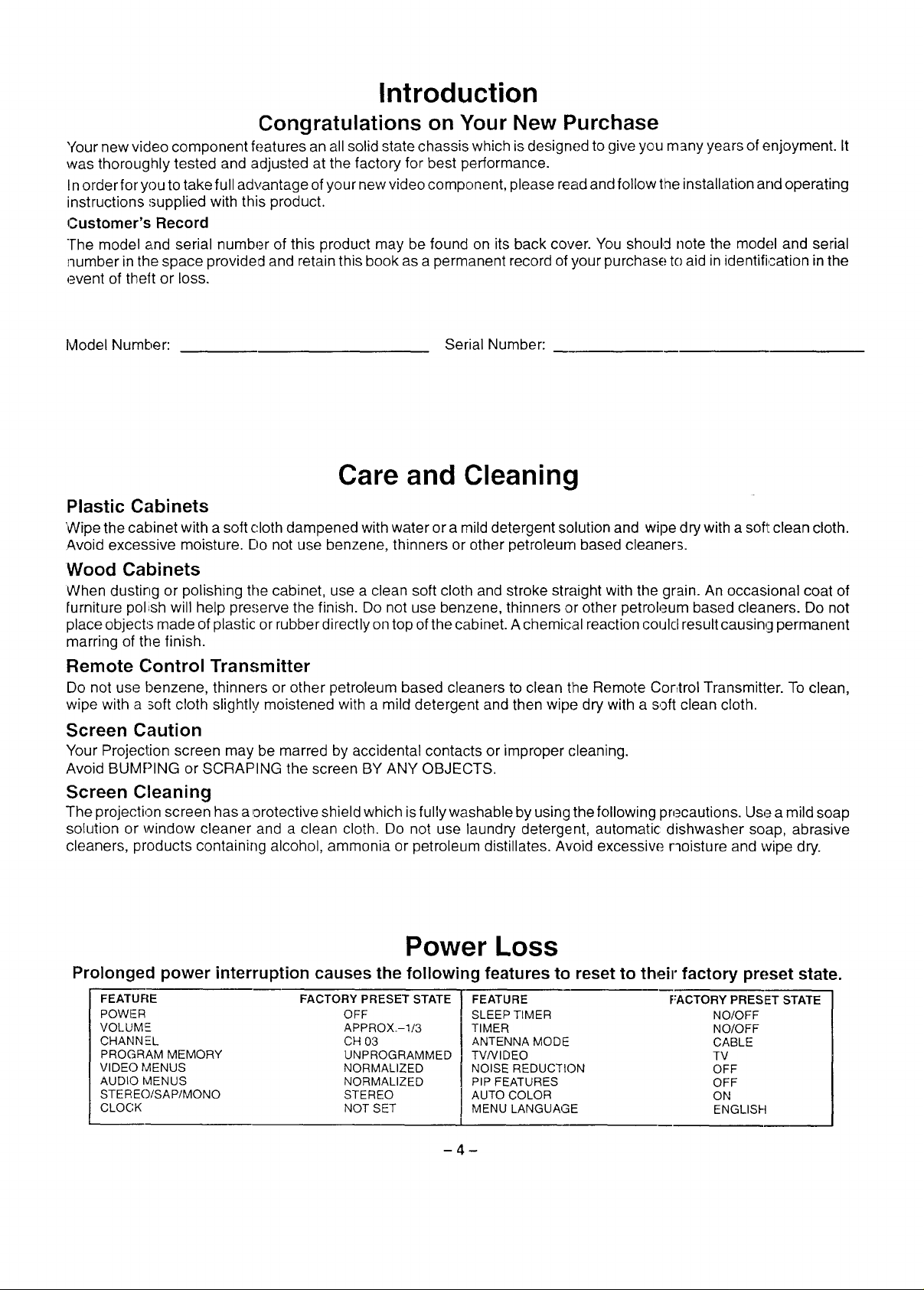
Power Loss
Prolonged power interruption causes the following features to reset to their factory preset state.
FEATURE FACTORY PRESET STATE
POWER OFF
VOLUMIE APPROX.-I/3
CHANNEL CH 03
PROGRAM MEMORY UNPROGRAMMED
VIDEO MENUS NORMALIZED
AUDIO MENUS NORMALIZED
STEREO/SAP/MONO STEREO
CLOCK NOT SET
FEATURE F.'ACTORY PRESET STATE
SLEEP TIMER NO/OFF
TIMER NO/OFF
ANTENNA MODE CABLE
TV/V IDEO TV
NOISE REDUCTION OFF
PIP FEATURES OFF
AUTO COLOR ON
MENU LANGUAGE ENGLISH
Table of Contents
Safety Instructions ............................. 2
Specifications ................................. 3
Introduction ................................... 4
Care and Cleaning ............................. 4
Power Loss .................................... 4
Installation .................................... 6
Receiver Location .............................. 6
Optional External Equipment Connections ........ 6
Condensation ................................. 6
AC Power Supply Cord ......................... 6
Remote Control Battery Installation .............. 6
Antenna/Cable Connections ..................... 7
Other Video Equipment ......................... 7
Optional Equipment Connection and Operation .. 8
Stereo Connection (to Audio AMP) .............. 8
Video/Audio Connection ........................ 8
S-Video Connection ............................ 9
PIP External Video and Antenna Connections ... 9
Location of Controls (Receiver) ................ 10
/.ocation of Controls (Remote) ................. 11
Basic Remete Control Functions ............... 11
Remote Control Quick Reference Functional
Key Chart ................................. 12
Special Functions ............................. 14
Recall Button ................................. 14
R-Tune (Rapid Tune) Button ................... 14
Multi Button .................................. 14
PIP (Picture in Picture) Button .................. 15
Swap Buttcn .................................. 15
Size Buttor .................................. 15
Freeze Button ................................ 15
Move Button ................................. 15
Main Menu (Trilingual Animated Icons) ......... 16
Menu Language Selection ................... 16
Picture Adj_Jstments ............................ 16
Picture Norm ............................... 16
Color, Tint, Brightness, Picture, and
Sharpness Adjustments ..................... 16
Color Temp ................................ 17
Auto Color ................................. 17
Video NR .................................. 17
Audio Adjustment ............................. 18
Audio Norm ................................ 18
Bass, Trehle, and Balance ................... 18
Mode (Stereo/SAP/Mono) ................... 18
Speaker ................................... 19
Surround .................................. 19
AI Sound .................................. 19
Input Select .................................. 20
Main (Picture) Input Selection ................. 20
PIP (Picture in Picture) Input Selection ........ 20
Timer Features ................................ 20
Sleep Timer ................................ 20
Dual Program Timer ......................... 21
Lockout Features ............................ 22
Lockout Mode .............................. 22
Unlock ..................................... 22
Favorite Channel Features ..................... 23
Channel Scan ............................... 23
Favorite Channel Select ..................... 23
Channel Caption Features ..................... 24
Preset Caption ............................. 24
Manual Caption ............................ 24
Set-Up Features .............................. 26
Clock (Auto) ............................... 26
Clock (Manual) ............................. 27
Set Day ................................... 27
Convergence Adj............................ 28
Mode (TV or Cable) ......................... 29
Auto Program .............................. 29
Manual Program ............................ 29
On Mute .............................. 30
r0-0--]Mode ................................ 30
Programming the Remote Control
Using Access Codes ....................... 31
Infrared Remote Codes for Specific Components 31
VCR Infrared Codes Inde:K ..................... 32
Cable Converter Box and CD Players
Infrared Codes Index ...................... 33
Cassette Players, AV Receivers, and Amplifiers
Infrared Codes Index ...................... 34
Laser Disc, DSS, and DVD
Infrared Codes Index ...................... 35
Cabinet Door Installation PT-51G46 ............ 36
Cabinet Door Installation PT-61G46 ............ 38
Troubleshooting Chart ........................ 40
Installation
P,eceiver Location
This unit can be used as an entertainment center. Consult your dealer for available options. Locate for comfortable
viewing. Avoid placing where sunlight or other bright light (including reflections) will fall on the screen.
Use of some types of fluorescent lighting can reduce remote control transmitter range.
AJequate ventilation is essential to prevent internal component failure. Keep away from areas of excessive heat or
moisture.
To insure optimum color purity do not position magnetic equipment (motors, fans, external speakers, etc.) nearby.
C)ptional External Equipment Connections
The Video/Audio connections between components should be made with shielded video _ncJaudio cables. For best
performance, video cables should utilize 75 - ohm coaxial shielded wire. Cables are available from your dealer or
electronic sup,ply house.
Before you purchase any cables, be sure you know what type of input and output connector_; your various components
rE'quire. Also determine the length of cable you'll need.
Condensation
When the set is moved into a warm room from a cold area, the picture may become out of focus because of
condensation on the lens surface due to the temperature change. Picture will be(;ome clear when the set
reaches the same temperature of the surrounding area.
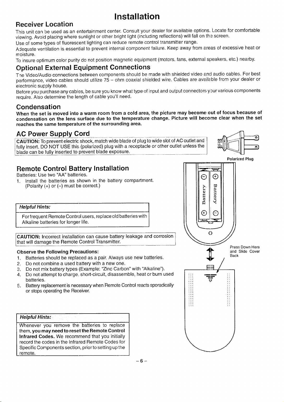
AC Power Supply Cord
CAUTION: To prevent electric shock, match wide blade of plug towide slot of AC outlet and
fully nsert. DO NOT USE this (polarized) plug with a receptacle or other outlet unless the
lblade can be fully inserted to prevent blade exposure.
Polarb:ed Plug
Remote Control Battery Installation
Batteries: Use two "AA" batteries.
1. Install the batteries as shown in the battery compartment.
(Polarity +) or (-) must be correct.)
Helpful Hints:
For frequent Remote Control users, replace old batteries with
Alkaline batteries for longer life.
CAUTION: Incorrect installation can cause battery leakage and corrosion
that will damage the Remote Control Transmitter.
Observe the Following Precautions:
1. Batteries should be replaced as a pair. Always use new batteries.
2. Do not combine a used battery with a new one.
3. Do not mix battery types (Example: "Zinc Carbon" with "Alkaline").
4. Do not attempt to charge, short-circuit, disassemble, heat or burn used
batteries.
5. Battery replacement is necessary when Remote Control reacts sporadically
or stops operating the Receiver.
!!/
::: _==== ..
::" T7 ..
::: --
Pres.,; Down Here
and Slide Cover
Back
Helpful Hints:
Whenever you remove the batteries to replace
them, you may need to reset the Remote Control
Infrared Codes. We recommend that you initially
record the codes in the Infrared Remote Codes for
Specific Components section, prior to setting up the
remote.
-6-
Installation (cont.)
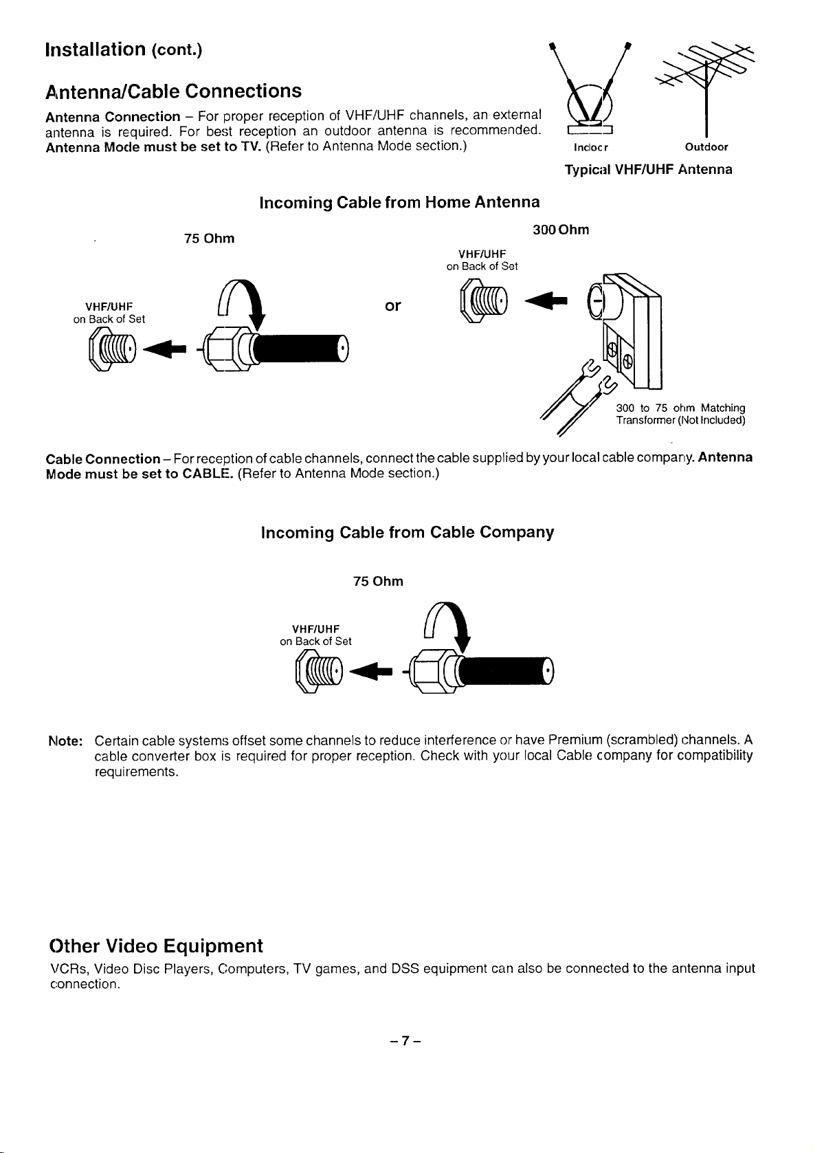
Antenna/Cable Connections
Antenna Connection - For proper reception of VHF/UHF channels, an external
antenna is required. For be.(;t reception an outdoor antenna is recommended.
Antenna Mode must be set to TV. (Refer to Antenna Mode section.)
Incoming Cable from Home Antenna
Incloc r Outdoor
Typical VHF/UHF Antenna
300 Ohm
300 to 75 ohm Matching
Transformer (Not Included)
VHF/UHF
on Back of Set
75 Ohm
VHF/UHF
on Back of Set
or
Cable Connection- For reception of cable channels, connect the cable supplied byyour local cable company. Antenna
Mode must be set to CABLE'. (Refer to Antenna Mode section.)
Incoming Cable from Cable Company
75 Ohm
VHF/UHF
on Back of Set
Note: Certain cable system.'_offset some channels to reduce interference or have Premium (scrambled) channels. A
cable converter box is required for proper reception. Check with your local Cable company for compatibility
requirements.
Other Video Equipment
VCRs, Video Disc Players, Computers, TV games, and DSS equipment carl also be connected to the antenna input
connection.
Optional Equipment Connection and Operation
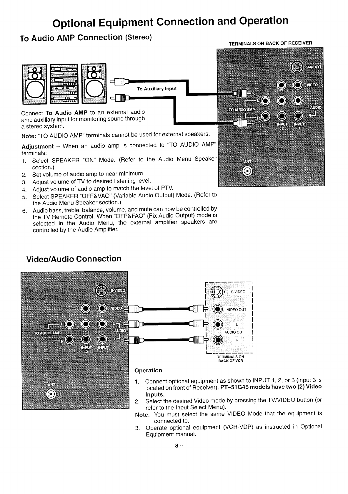
"1"oAudio AMP Connection (Stereo)
To Auxiliary Input
Connect To Audio AMP to an external audio
amp auxiliary input for monitoring sound through
e.stereo system.
Note: "TO AUDIO AMP" terminals cannot be used for external speakers.
Adjustment - When an audio amp is connected to "TO AUDIO AMP"
terminals:
1. Select SPEAKER "ON" Mode. (Refer to the Audio Menu Speaker
section.)
2. Set volume of audio amp to near minimum.
:3. Adjust volume of TV to desired listening level.
4. Adjust volume of audio amp to match the level of PTV.
5. Select SPEAKER "OFF&VAO" (Variable Audio Output) Mode. (Refer to
the Audio Menu Speaker section.)
6. Audio bass, treble, balance, volume, and mute can now be controlled by
the TV Remote Control. When "OFF&FAD" (Fix Audio Output) mode is
selected in the Audio Menu, the external amplifier speakers are
controlled by the Audio Amplifier.
TERMINALS 'DN BACK OF RI--CEIVER
Video/Audio Connection
IIF--- S-v,DEO
VIDEO OUT
I AUDIO OUT
I
I,
lrERMINALS ON
BACK OF VCR
Operation
1. Connect optional equipment as shown to INPUT 1,2, or ,'3(input 3 is
located on front of Receiver).. PT-51G46 rncdels have two (2) Video
Inputs.
2. Select the desired Video mode by pressing the TV/VIDEO button (or
refer to the Input Select Menu).
Note: You must select the same VIDEO rv'oclethat the equipment is
3. Operate optional equipment (VCR-VDP) as instructed in Optional
connected to.
Equipment manual.
-8-
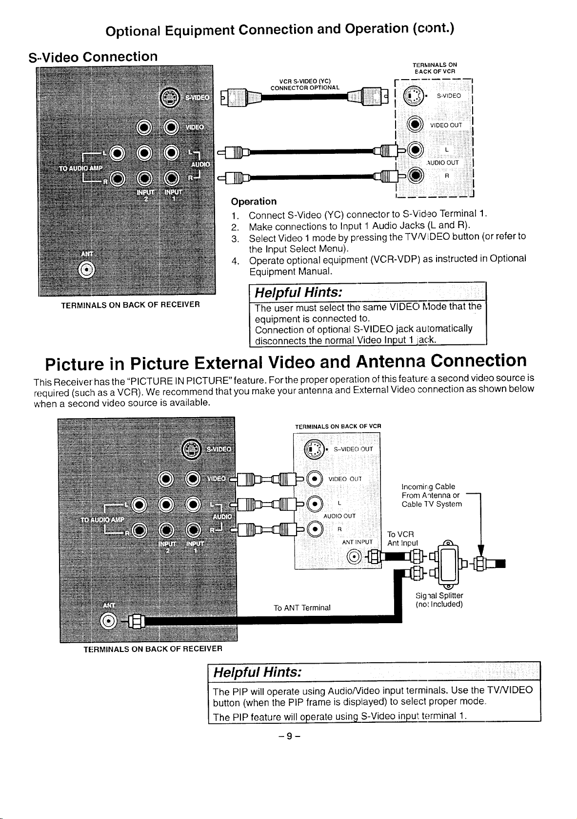
Optional Equipment Connection and Operation (cont.)
S..Video Connection
T|'RMINALS ON
BACK OF VCR
VCR S-VIDEO (YC)
CONNECTOR OPTIONAL
[ ......
_b,'_ S-VIDEO; i
VIDEO OUT
•UD_OOU
R I
Operation
1. Connect S-Video (YC) connector to S-Video Terminal 1.
2. Make connections to Input 1 Audio Jacks (L and R).
3. Select Video 1 mode by pressing the TV/VIDEO button (or refer to
the Input Select Menu).
4. Operate optional equipment (VCR-VDP) as instructed in Optional
Equipment Manual.
TERMINALS ON BACK OF RECEIVER
The User must select the same VIgEO'_locle that the I
equipment is connected to. I
Helpful Hints: I
Connection of optional S-VIDEO jack automatically I
disconnects the normal Video Input 1 iack. J
Picture in Picture External Video and Antenna Connection
This Receiver' has the "PICTURE INPICTURE" feature. For the proper operation of this featurE,a second video source is
required (such as a VCR). We recommend that you make your antenna and External Video connection as shown below
when a second video source is available.
TERMINALS ON BACK OF VCR
Incornir_g Cable
From Antenna or
Cable 1V System
To VCR
TE-RMINALS ON BACK OF RECEIVER
Sig "_alSplitter
(not Included)
I Heipful Hints: :
The PIP will operate using Audio/Video input terminals. Use the TV/VIDEO I
button (when the PIP frame is displayed) to select proper mode. ,I
The PIP feature will operate using S-Video input tE.rminal 1. J
9
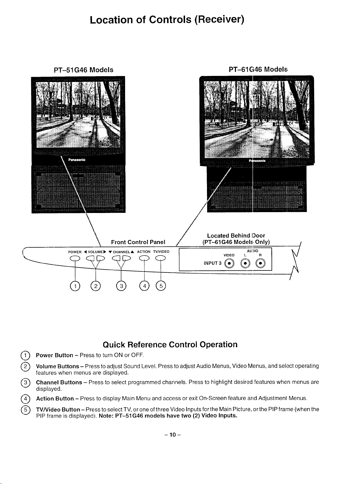
Location of Controls (Receiver)
PT-51 G46 Models
\_ Front Control Panel
POWER • VOI..UMEII_ Y CHANNFLA ACTION W/VIDEO
PT-61 C146Models;
Located Behind Door
(PT-61G46 Models Only)
VIDEO L R
AUI)IO
®
Quick Reference Control Operation
(1_ Power Button - Press to turn ON or OFF.
(2_) Volume Buttons- Press to adjust Sound Level. Press to adjust Audio Menus, Video Menus, and select operating
features when menus are displayed.
(3_) Channel Buttons - Press to select programmed channels. Press to highlight desired features when menus are
displayed.
(4_) Action Button - Press to display Main Menu and access or exit On-S(-reen feature arid Adjustmenl Menus.
(5_) TV/Video Button- Press to select TV, or one of three Video Inputs for the Main Picture, or the PIP frame (when the
PIP frame is displayed). Note: PT-51G46 models have two (2) Video Inputs.
-10-
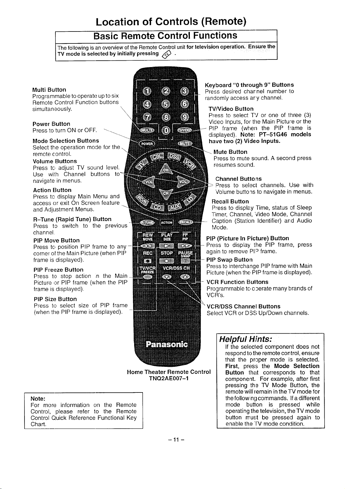
Location of Controls (Remote)
f Bas Remot_ eCon_ _tro_ lFunc___tion_ s
The following isan overvewof the RemOteControluntfor televisionoperation. Ensurethe
TV mode is selected by initiallypressing _ .
Multi Button
Programmable to operate up to six
Remote Control Function buttons
simultaneously.
Power Button
Press to turn ON or OFF.
Mode Selection Buttons
Select the operation mode for the
remote control.
Volume Buttons
Press to adjust TV sound level.
Use with Channel buttons
navigate in menus.
Action Button
Press te display Main Menu and
access or exit On Screen feature
and Adjustment Menus.
R-Tune (Rapid Tune) Button
Press to switch to the previous
channel.
PIP Move Button
Press to position PIP frame to any
corner of the Main Picture (when PIP
frame is displayed).
PIP Freeze Button
Press to stop action ;n the Main
Picture ,DrPIP frame (when the PIP
frame is displayed).
PIP Size Button
Press to select size of PIP frame
(when the PIP frame is displayed).
Keyboard "0 through 9" Buttons
Press desired charnel number 1:o
randomly access ary channel.
TV[Video Button
Press to select TV or one of three (3)
Video Inputs, for the Main Picture or the
PIP frame (when the PIP flame is
displayed). Note: PT-51G46 models
have two (2) Video Inputs.
Mute Button
Press to mute sound. A second press
resumes sound.
Channel Butto ns
Press to select channels. Use with
Volume buttons to navigate in menus.
Recall Button
Press to displa.y Time, status of Sleep
-I-imer, Channel, Video Mode, Channel
Caption (Station Identifier) and Audio
Mode.
PIP (Picture In Picture) Button
Press to display the PIP frame, press
again to remove PII_ frame.
PIP Swap Button
Press to interchange PIP frame with Main
Picture (when the, PIP frame is displayed).
VCF:IFunction Bultons
Programmable to oaerate many brands of
VC:R's.
VCR/DSS Channel Buttons
Select VCR or DSS Up/Down channels.
Home Theater Remote Control
Note:
For more information on the Remote
Control, please refer to the Remote
Control Quick Reference Functional Key
Chart.
TNQ2AE007-1
-11 -
Helpful Hints:
If the selecled component does not
respond to the remote control, ensure
that the proper mode is selected,
First, press the Mode Selection
Button that corresponds to that
component. For example, after first
pressing th£ TV Mode Button, the
remote will remain inthe TV mode for
the following commands. Ifa different
mode button is pressed while
operating the television, the TV mode
button must be pressed again to
enable the -i-V mode condition.
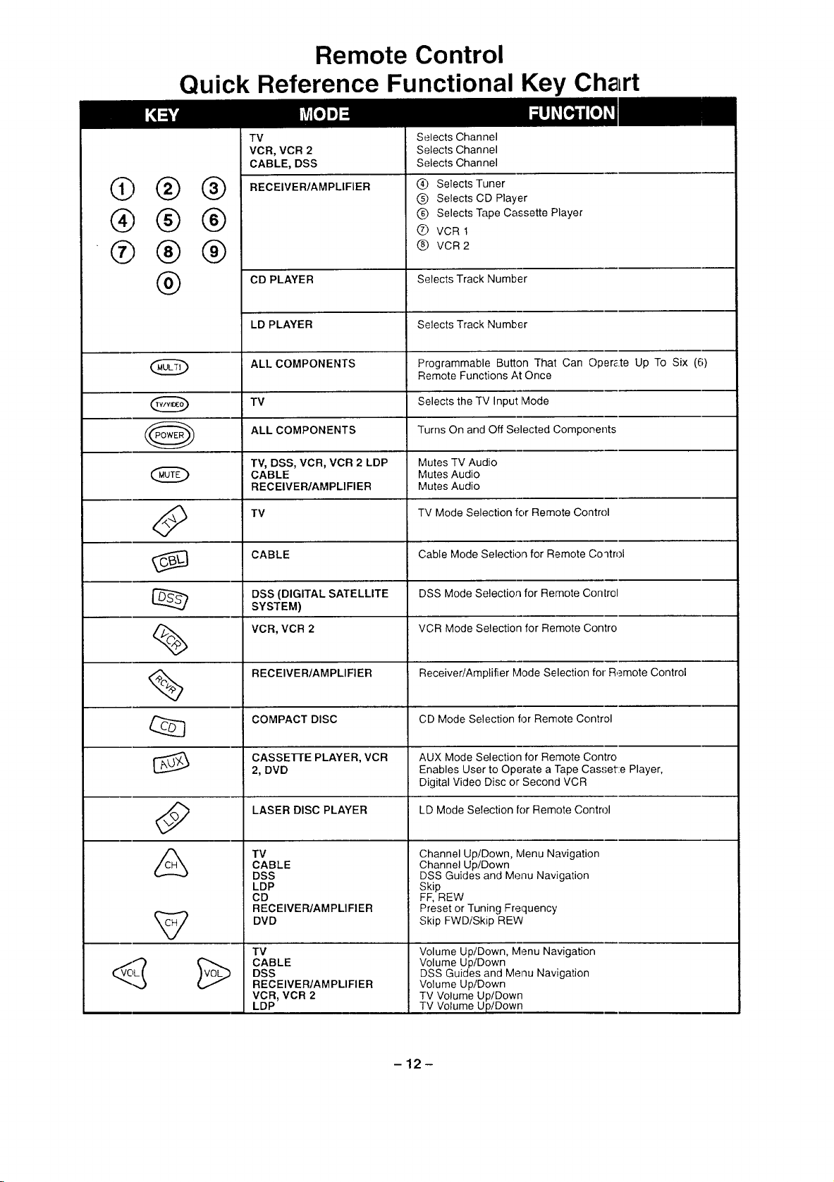
Remote Control
Quick Reference Functional Key Chart
C)
@
®
®
®
®
®
0
@
®
®
®
TV
VCR, VCR2
CABLE, DSS
RECEIVER/AMPLIFIER
CD PLAYER
LD PLAYER
ALL COMPONENTS
TV
ALL COMPONENTS
T% DSS, VCR, VCR2LDP
CABLE
RECEIVER/AMPLIFIER
TV
Selects Channel
Selects Channel
Selects Channel
Q Selects Tuner
(_) Selects CD Player
(_ Selects Tape Cassette Player
® VCRt
@ VCR 2
Selects Track Number
Selects Track Number
Programmable Button That Can Oper_.te Up To Six (6)
Remote Functions At Once
Selects the TV Input lVlode
Turns On and Off Selected Compone_
Mutes TV Audio
Mutes Audio
Mutes Audio
TV Mode Selection for Remote Contr(
CABLE Cable Mode Selection for Remote Coqtrol
DSS (DIGITAL SATELLITE DSS Mode Selection for Remote Con
SYSTEM)
VCR, VCR 2 VCR Mode Selection for Remote Con
RECEIVER/AMPLIFIER Receiver/Amplifier Mode Selection for Remote Control
COMPACT DISC CD Mode Selection for Remote Contr
CASSEFrE PLAYER, VCR AUX Mode Selection for Remote Con
2, DVD Enables User to Operate a Tape Cas.' Player,
LASER DISC PLAYER LD Mode Selection for Remote Contn
TV
CABLE
DSS
LDP
CD
RECEIVER/AMPLIFIER
DVD
TV
CABLE
DSS
RECEIVEWAMPLIFIER
VCR, VCR2
LDP
Digital Video Disc or Second VCR
Channel Up/Down, Menu Navigation
Channel Up/Down
DSS Guides and Menu Navigation
Skip
FF, REW
Preset or Tuning Frequency
Skip FWD/Skip REW
Volume Up/Down, Menu Navigation
Volume Up/Down
DSS Guides and Menu Navigation
Volume Up/Down
TV Volume Up/Down
TV Volume Up/Down
-12-
 Loading...