

Page 1
Studio Card
AW-PB301/PB305
Before attempting to connect or operate this product,
please read these instructions completely.
Page 2
NOTE: This equipment has been tested and found to comply with the limits for a Class A digital device, pursuant to
part 15 of the FCC Rules. These limits are designed to provide reasonable protection against harmful interference
when the equipment is operated in a commercial environment. This equipment generates, uses, and can radiate
radio frequency energy and, if not installed and used in
accordance with the instruction manual, may cause harmful
interference to radio communications. Operation of this
equipment in a residential area is likely to cause harmful
interference in which case the user will be required to correct the interference at his own expense.
This digital apparatus does not exceed the Class A limits for
radio noise emissions from digital apparatus set out in the
Radio Interference Regulations of the Canadian Department
of Communications.
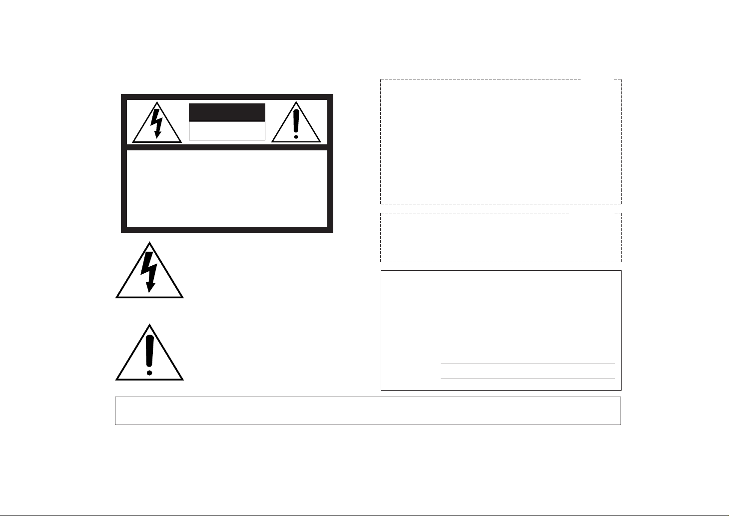
WARNING:
TO PREVENT FIRE OR SHOCK HAZARD, DO NOT EXPOSE THIS APPLIANCE TO RAIN OR MOISTURE.
The lightning flash with arrowhead symbol, within an equilateral triangle, is
intended to alert the user to the presence of uninsulated "dangerous voltage"
within the product's enclosure that may
be of sufficient magnitude to constitute a
risk of electric shock to persons.
The exclamation point within an equilateral triangle is intended to alert the user
to the presence of important operating
and maintenance (servicing) instructions
in the literature accompanying the appliance.
The information marking of this product may be found on the
bottom of the unit.
The serial number of this product may be found on the bottom of the unit.
You should note the serial number of this unit in the space
provided and retain this book as a permanent record of your
purchase to aid identification in the event of theft.
Model No.
Serial No.
CAUTION:
TO REDUCE THE RISK OF ELECTRIC SHOCK, DO
NOT REMOVE COVER (OR BACK). NO USER SERVICEABLE PARTS INSIDE.
REFER SERVICING TO QUALIFIED SERVICE PERSONNEL.
CAUTION
RISK OF ELECTRIC SHOCK
DO NOT OPEN
SA 1965
SA 1966
For U.S.A
For CANADA
Page 3

-1-
CONTENTS
PREFACE ................................................................................................................................................................................ 2
SPECIAL NOTES ON OPERATION ......................................................................................................................................... 2
PRECAUTIONS ....................................................................................................................................................................... 3
MAJOR OPERATING CONTROLS AND THEIR FUNCTIONS ................................................................................................. 4
MOUNTING ............................................................................................................................................................................ 5
CONNECTING A STUDIO SYSTEM ....................................................................................................................................... 7
MENU ITEM SETTING ............................................................................................................................................................ 8
APPEARANCE ........................................................................................................................................................................ 12
SPECIFICATIONS ................................................................................................................................................................... 13
STANDARD ACCESORIES ..................................................................................................................................................... 13
Page 4

-2-
• When the studio card AW-PB301/AW-PB305 is
installed in a convertible camera, for example, AWE300, the electronic viewfinder (EVF) and intercom
will be usable, making it possible to use the camera
in studios.
PREF ACE
• When the studio card AW-PB301 is installed in a
convertible camera, for example, AW-E300, R/G/B
or Y/Pr/Pb component signals can be output.
• When the studio card AW-PB305 is installed, only
composite video signals and Y/C signals will be
output.
SPECIAL NOTES ON OPERATION
• Power Off Before Connecting or Disconnecting
Cables
Before plugging or unplugging the cables, be sure
to switch power off.
• Handle Carefully.
Do not drop the product, or subject it to strong
shock or vibration. This is important to prevent trouble.
• Avoid Humidity and Dust.
Avoid using the product at a humid, dusty place
because much humidity and dust will cause damage to the parts inside.
• Operating Temperature Range
Avoid using the product at a cold place below 10°C or at a hot place above +45°C because
extremely low or high temperature will adversely
affect the parts inside.
Page 5

PRECAUTIONS
• Ask a qualified service person for repairs when
necessary.
• Do not attempt to disassemble the camera, Remote
Control Unit (RCU) or other units. In order to prevent electric shock, do not remove screws or covers. There are no user-serviceable parts inside.
• Do not let water, metal, or other foreign objects
inside. This is important to prevent fire and electric
shock.
• If you see smoke or smell an odor from the product,
if water or other foreign matter gets inside, if it is
damaged by dropping, or if you find anything
wrong with it, immediately stop using it.
-3-
Page 6

MAJOR OPERATING CONTROLS AND THEIR FUNCTIONS
-4-
q Viewfinder connector [EVF]
Connect the cable for the viewfinder mounting
bracket AW-Q40.
w Viewfinder standby switch [ST.BY/ON]
When this switch is set to [ST.BY], the viewfinder will
be in standby condition.
The position ON, the picture is shown in the viewfinder screen.
e Intercom volume control [LEVEL]
Used to adjust intercom volume level.
r Intercom connector [INCOM]
Connect an intercom to this connector.
If the intercom plug has a different diameter, use the
conversion adapter supplied as an accessory.
LEVEL
INCOM
EVF
ST.BY
ON
Viewfinder connector
Viewfinder standby switch
Intercom volume control
Intercom connector
Page 7

-5-
MOUNTING
• Be sure to ask your store, where you purchased
the product, for mounting.
• Disconnect the camera power connector before
mounting.
• Before handling the card, touch a metal part of
the camera to discharge the static from the
human body.
An anti-static wrist strap is recommended for
added safety.
If you touch the card while you are still charged
with static, it may cause trouble.
• Keep the metal parts of the card free of contact
with other metal parts.
(1) Switch the camera off, and disconnect the power
connector and other cables from the camera.
(2) Loosen the four screws on the rear of the camera
and remove the rear panel.
(3) Loosen the two screws for the option card slot and
remove the cover.
(4) Insert the Studio card along the guide rail at the
bottom of the camera and the tab above.
Insert it securely all the way.
(5) Tighten the two card setscrews securely.
If you have lost the screws, use the screws (6 mm
long) supplied as accessories.
(6) Fasten the rear panel with the four screws.
If you have lost the screws, use the screws (8 mm
long) supplied as accessories.
(7) Plug the cables back as necessary, connect the
power connector, then switch power on.
CAUTION
Page 8

-6-
Panasonic
Panasonic
Option card slot cover
Studio card
Card setscrews (6 mm)
Rear Panel
Rear panel
setscrews (8 mm)
Page 9

-7-
• To connect an RCU (WV-RC700A or WV-RC550) to the camera, use the RCU cable AW-CA50A26.
• To mount the 5-inch electronic viewfinder WV-VF65C on the camera, use the viewfinder mounting bracket AW-Q40.
• Power is supplied from the RCU.
GEN-LOCKINAUX
IN
AUTO
75
/Hi-Z
AUTO
75¶/Hi-Z
R/PR /C
OUT OUT
AUDIO
SEE MANUAL
VIDEO 1
G/Y/Y VIDEO 2
B/PB /B SYNC
S-VIDEO
14
23
TALLY
CAMERA (MULTI)
CABLE SELECT
FUSE
250V 1.25A
TALK
INCOM
RECEIVE
CONTROL
TALLY & INCOM
MULTI OVP
MPX
MPX
OUTPUT
RCU cable
AW-CA50A26 (15 m)
RCU WV-RC700A
AC120V
60Hz
Cable selector switch
(Set it to MULTI.)
Panasonic
Viewfinder mounting bracket AW-Q40
Push viewfinder
from behind
Turn clamp knob
to fasten camera.
Turn clamp knob
to fasten securely.
5" electronic viewfinder
WV-VF65C
To IF/REMOTE
To EVF
CONNECTING A STUDIO SYSTEM
Page 10

-8-
MENU ITEM SETTING
● MAIN MENU SCREEN
**Halogen Mode Set**
Brightness Set
Color Set
G/L. Color Bar Set
Sharpness Set
Other Set
Option Card Set
Initialize Data
End
Use Mode
Blinking
**User Mode Set**
Iris, Shutter, Gain Set
Color Set
G/L. Color Bar Set
Detail Set1 Detail Set2
Color Matrix Set
Other Set
Option Card Set
Initialize Data
End
Main Menu of Halogen,
Fluorescent, Outdoor Mode
Main Menu of User Mode
A convertible camera, for example, AW-E300, can be
set using the menu as suited to the system and shooting conditions. For details, refer to the operation manual for the camera.
■ Setup Procedures (Output Signal
Selection)
(1) Display the main menu.
Camera alone: Keep the menu switch depressed
for 5 seconds or more.
With RCU (RCB): Set the user set switch in the
pocket to ON.
Page 11

-9-
–
+
MENU
ITEM/AWC
YES/ABC
NO/BAR
OPTION CARD
VIDEO OUT
I/F REMOTE
G/L IN
IRIS
DC12V IN
MENU Switchi“j
LEVEL
INCOM
EVF
ST.BY
ON
ITEM Switchi«j
NO Switchi|j
YES Switchi{j
PAGE ITEM UP DOWN
COARSE FINE
SC PHASE
270°
180°90°
0°
H.PHASE
USER SET
OFFENC
VF ON
User Set Switch
PAGE Switch
ITEM Switch
UP Switch
DOWN Switch
CAMERA
RCU (RCB)
(2) The setting item (flashing) changes each time the
menu switch, item switch, or NO switch is pressed.
Select [Option Card Set] and press the YES switch
to display the [Option Card Set] submenu.
(3) Select an item to set using the menu switch and
item switch.
(4) Change the settings using the YES and NO switch-
es.
(5) Select [Return] with the menu switch and item
switch, and press the YES switch to return to the
main menu.
(6) The camera is now back in shooting condition.
Camera alone: Select [End] with the menu switch
and item switch, then press the YES switch.
With RCU (RCB): Set the user set switch in the
pocket to OFF.
The camera will now operate under the conditions
thus set.
Page 12

-10-
**Opation Card Set**
Zebra Indicator ON
Zebra 1 Level 70%
Zebra 2 Level 85%
Safety Zone I
EVF Output Y
Component R/G/B
Return
**Opation Card Set**
Zebra Indicator ON
Zebra 1 Level 70%
Zebra 2 Level 85%
Safety Zone I
EVF Output Y
Return
AW-PB301 AW-PB305
■ Option Card Setting Submenu
q Zebra Indicator [Zebra Indicator: OFF/ON]
ON: Zebra indicator is shown in the viewfinder.
OFF: Zebra indicator is not shown in the viewfinder.
Note: If [CVBS] is selected at Item [EVF Output:
Y/CVBS] r, the zebra indicator will not be
shown.
w Zebra 1 Level Set [Zebra 1 Level: 70% to 109%]
Zebra 2 Level Set [Zebra 2 Level: 71% to 110%]
Zebra level 1 or 2 can be only when Zebra Indicator
q is at ON.
The zebra indicator can be shown in two steps
using two zebra patterns.
2 Level shows a finer zebra pattern than 1 level.
2 Level must be set at least 1% higher than 2 level.
e Safety Zone Select [Safety Zone: 1 to 5/OFF]
A type of safety zone to be shown in the viewfinder
can be selected.
No safety zone is shown if OFF is selected.
Page 13

-11-
12 3
45
The inner frame indicates a safety zone of about
90% and the outer frame, a safety zone of about
95%.
Note: The safety zone and center marker indicate
electrical positions, which may differ from optical positions.
r Viewfinder Output Signal Select [EVF Output:
Y/CVBS]
Y: Luminance signals are output to the viewfinder.
CVBS: Color signals are output to the viewfinder.
No zebra indicator will be shown.
t Component Output Select [Component Output:
R/G/B, Y/Pr/Pb, Y/C] (AW-PB301 only)
Component output signals can be selected.
Component output signals are output from the interface/remote connector on the rear of the camera.
Note: R/G/B output or Y/Pr/Pb output will be posi-
tive in reproduced image regardless of the settings made with [Nega/Posi Set] on the [Other
Settings] submenu of the main menu.
Page 14

-12-
APPEARANCE
mm (inch)
LEVEL
INCOM
EVF
ST.BY
ON
70 (2-3/4)
21.5
(27/32)
96 (3-3/4)
91 (2-3/4)
5 (3/16)
Page 15

-13-
Video output: Y/C: Y: 1.0 V[p-p], C: 0.286 V[p-p]
R/G/B: 0.7 V[p-p] (AW-PB301 only)
Y/Pr/Pb: Y: 1.0 V[p-p], Pr/Pb: 0.7 V[p-p] (AW-PB301 only)
SYNC: 2.0 V[p-p] sync signal (AW-PB301 only)
VF output: 1.0 V[p-p], composite, high impedance
Intercom jack: 3.5 mm in diameter
Switch: Switching on the panel: EVF ST-BY/ON
Switching on the menu: Zebra indicator ON/OFF, safety zone switching, EVF output switching,
component output switching (AW-PB301 only)
Adjusting functions: Intercom voice output level adjusted on the panel
Zebra level adjusted using the menu
Source voltage: 12 VDC (supplied from camera)
Power consumption: 3.8 W (AW-PB301), 0.5 W (AW-PB305)
Operating temperature: –10°C to +45°C (14°F to +113°F)
Operating humidity: 30 % to 90 %
Dimensions: 21.5 (W) x 70 (H) x 96 (D) mm [27/32” x 2-3/4” x 3-3/4”]
Weight: 105 g
Weight and dimensions indicated are approximate.
Specifications are subject to change without notice.
SPECIFICATIONS
Intercom plug adapter
(6.35 mm to 3.5 mm in diameter) ........................... 1 pc
STANDARD ACCESSORIES
Screw (6 mm long) ................................................ 2 pcs
Screw (8 mm long) ................................................ 4 pcs
Page 16

N1098-0 7J1A215A Printed in Japan
Broadcast & Television Systems Company
Division of Matsushita Electric Corporation of America
Executive Office: One Panasonic Way 3F-5, Secaucus, NJ 07094
Regional Offices:
EASTERN ZONE: 50 Meadowlands Parkway, Secaucus, NJ 07094 (201) 348-7620
CENTRAL ZONE: 1707 North Randall Road, Elgin, IL 60123 (847) 468-5200
SOUTHERN ZONE:
Atlanta Region: 1225 Northbrook Parkway, Suite 1-160, Suwanee, GA 30024
Panazip 11 (770) 338-6841, fax (770) 338-6741
Law Enforcement Video Products: 1225 Northbrook Parkway, Suite 1-160, Suwanee,
GA 30024, Panazip 11 (770) 338-6844, fax (770) 338-6721
WESTERN ZONE:
Seattle Region: 1200 Westlake Ave. North, Suite 508, Seattle, WA98109 (206) 285-8883
Los Angeles Region: 6550 Katella Ave. 17A-1, Cypress, CA 90630 (714) 373-7271
Government Marketing Department: 52 West Gude Drive, Rockville, MD 20850 (301) 738-3840
PANASONIC CANADA INC.
5770 Ambler Drive, Mississauga, Ontario, L4W 2T3 Canada (905) 624-5010
PANASONIC SALES COMPANY
DIVISION OF MATSUSHITA ELECTRIC OF PUERTO RICO, INC.
San Gabriel Industrial Park, 65th Infantry Ave. KM. 9.5 Carolina, Puerto Rico 00630 (809) 750-4300
 Loading...