

Panasonic PAW-HPM 1, PAW-HPM 2 User Manual

Panasonic
Aquaarea
Heat pump manager
PAW-HPM 1
PAW-HPM 2
Manual, part 1
Installation and commissioning
©Copyright Panasonic, Germany, 2013

COPYRIGHT
Panasonic. All rights reserved.
Windows, Windows 2000, Windows XP, and Windows Server 2003 are registered trademarks of Microsoft
Corporation.
Some product names mentioned in this document are used for identification purposes only and may be the
registered trademarks of their respective companies.
Revision A, February 2013
Software revision: 1.0-0-00
NOTICE:
Before removing the controller from the terminal block, be sure to switch
off the supply voltage!

2
Part I Installation and
startup

3
Table of contents
Part I Installation and startup
CHAPTER 1 GENERAL INFORMATION........................................................................ 4
1.2 HPM TOOL – SELECTING THE SYSTEM DIAGRAM .............................................................. 5
1.3 MODEL OVERVIEW AND ACCESSORIES ........................................................................... 6
1.4
THE HPM-PACKAGE .................................................................................................. 6
1.5THE CONTROLLER ....................................................................................................... 7
1.5.1 The control elements .................................................................................. 7
1.5.2 The default display ...................................................................................... 7
1.5.3 The main operating mode switch ................................................................ 8
1.5.4 System overview.......................................................................................... 9
1.5.5 Overtime ...................................................................................................... 9
1.5.6 Maintenance / acknowledgment ................................................................ 9
1.6 THE SOCKET ........................................................................................................... 10
1.7 THE INTERFACES ...................................................................................................... 11
1.8 TECHNICAL DATA ..................................................................................................... 12
CHAPTER 2 INSTALLATION AND WIRING ................................................................ 13
2.1 INSTALLATION ......................................................................................................... 13
2.1.1 Wall mounting ........................................................................................... 13
2.1.2 Mounting in a control cabinet door .......................................................... 14
2.1.3 Mounting in control cabinet on DIN-rail ................................................... 14
2.2 WIRING ................................................................................................................. 15
2.2.1 General ...................................................................................................... 15
2.2.2 Main voltage .............................................................................................. 15
2.2.3 Input terminals .......................................................................................... 16
2.2.4 0…10V (Universal terminals) ..................................................................... 18
2.2.5 Output terminals ....................................................................................... 19
2.2.7 Connection with the heat pump................................................................ 22
CHAPTER 3 INITIAL INSTALLATION ......................................................................... 26
3.1 SELECTING A SYSTEM DIAGRAM - HPM TOOL ................................................................ 26
3.2 LOADING THE SYSTEM DIAGRAM ................................................................................. 28
3.2.1 Initial loading of the system diagram ........................................................ 29
3.2.2 Reloading the system diagram .................................................................. 30
3.2.3 Manual configuration (loading of diagram “99999”) ................................ 30
3.3 ADDITIONAL ADJUSTMENTS ....................................................................................... 32
3.3.1 The menu structure ................................................................................... 32
3.3.2 Access codes .............................................................................................. 33
3.3.3 Aquarea basic configuration (only needed for connection via Bus) ......... 34
3.3.4 Domestic hot water – Setpoints ................................................................ 34
3.3.5 Heating Circuits – Setpoints, heating curve, setpoint limitation ............... 35
3.3.6 System – time and date ............................................................................. 36
3.3.7 Occupation times....................................................................................... 36
3.3.8 Operating mode switch ............................................................................. 37
3.3.9 Testing the functionality ............................................................................ 37
3.3.10 Screed drying ........................................................................................... 38
CHAPTER 4 APPENDIX ............................................................................................ 39
4.1 THE DISPLAYING OF ERROR MESSAGES ......................................................................... 39
4.2 HEATING CURVES .................................................................................................... 40
4.3 TABLE OF MEASURING VALUES OF THE SENSORS ............................................................. 41
4.4 MENU STRUCTURE ................................................................................................... 42

4
Chapter 1 General information
This operating manual consists of a detailed description of the installation and
commissioning of the HPM controller. The manual describes the individual parts of
the controller as well as its operation, how to connect sensors, pumps and valves,
selecting the system diagram and how to make additional adjustments to adapt the
controller to the construction of a individual system and its installed heat pump(s).
The appendix of the manual contains the most common system diagrams along with
the complete menu structure, an overview of the available types of heat pumps (type
of communication), an overview of the possible heating curves, a description of
cascade control (i.e. using more than one heat pump with communication) and
information for configuring web communication (Ethernet/network interface).
To simplify controller operation, its display will show only such parameters and menu
items that are currently relevant. I.e., if a boiler has been selected as the heat source,
menus pertaining to the operation of district heating and heat pumps will not be
visible. Or, supposing there is no return temperature sensor assigned to a terminal, no
entry will be visible in the menu ”Current values” pertaining to a return temperature.
The selected and loaded system diagram, along with any additional manual
adjustments made, decide what will be displayed in the menu system of the controller.
5
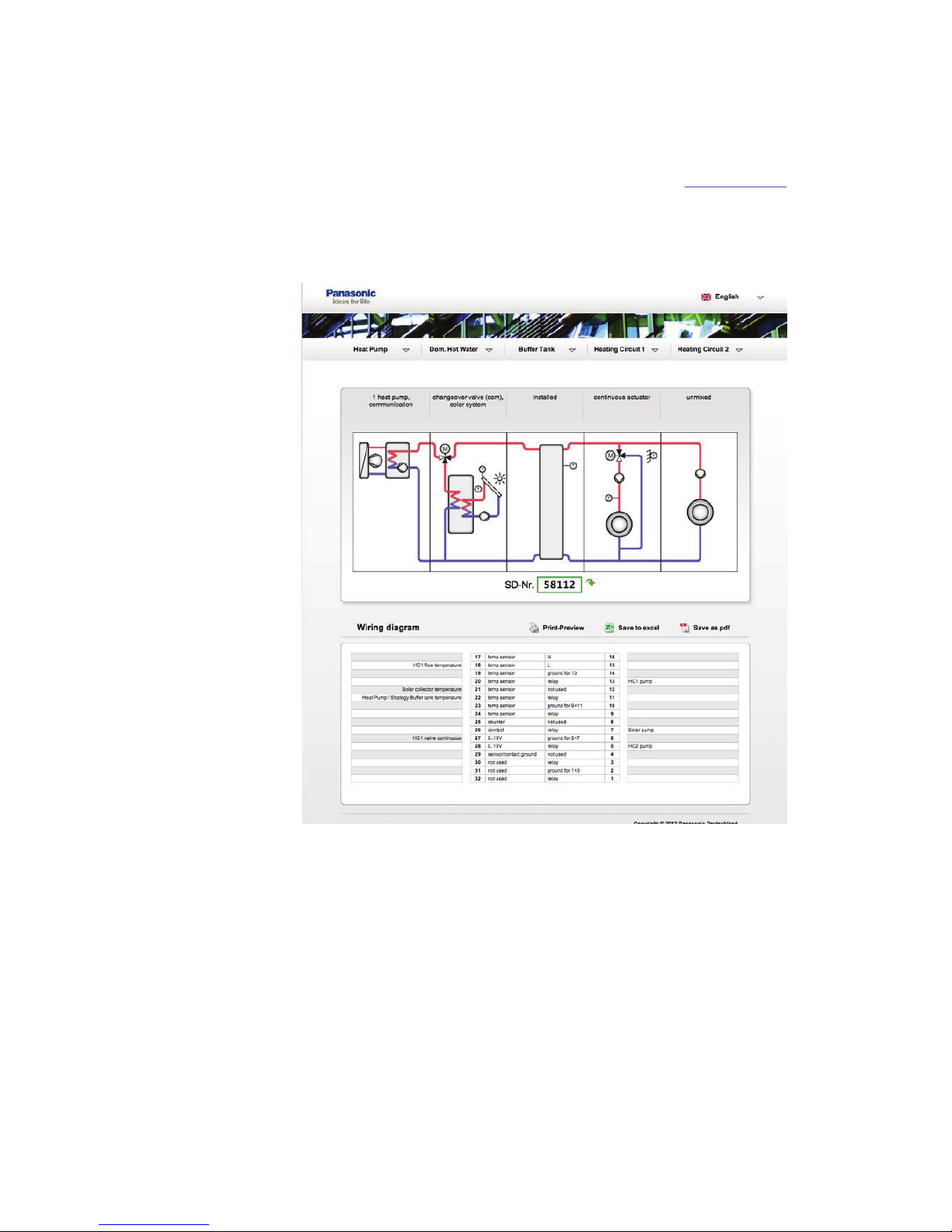
1.1 HPM tool: Selecting the system diagram
To select the system diagram, Panasonic offers a web-based tool called “HPM tool”.
HPM tool is a web-based software accessible via the address
www.hpmtool.eu by
using a standard Internet browser
HPM tool permits quick and easy selection of the right system diagram for your
heating system.
Fig 1.1: Different modules are combined into a system diagram. HPM tool then provides a system diagram
number which is entered into the controller and the corresponding terminal configuration
By making selections from the menu system near the top of the screen, the modules
can be combined into a system diagram corresponding to the actual heating system in
use. HPM tool then generates a system diagram number. This has to be entered during
initial startup of the controller.
The terminal configuration displayed in HPM-tool shows to which input and output
terminals the sensors, pumps and valves must be connected. The terminal
configuration can either be printed out or saved as a Microsoft Excel file.
6
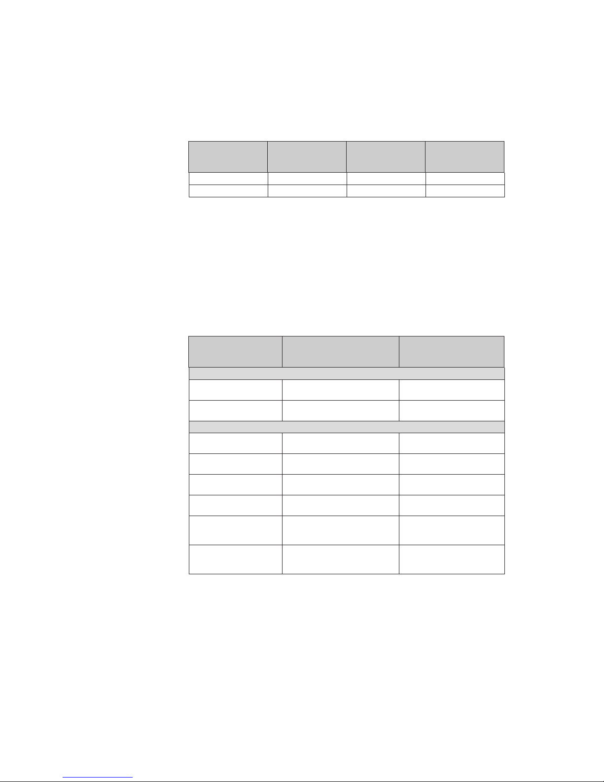
1.2 Model overview and Accessories
The product range of the PAW-HPM consists of the HPM controller (with or without
display), the adapter cable (enabling communication with a split- or mono-block heat
pump) and miscellaneous sensors:
Controller type Display and Keys BUS * Web
PAW-HPM1
XXX
PAW-HPM2
X
X
* Communication with a heat pump requires additional adapter cable of model INT-X
Table 1.1: Controller types
The HPM1 is a standardized controller for systems including a heat pump. Control of
the heat pump can take place either via a contact or via communication. A HPM
controller can be used for cascade control of up to 3 heat pumps. For demand via
contact, only one HPM1 is required. When utilising cascade control via a
communication port, one HPM1 is required as a master controller and up to 2 HPM2
as slave controllers (for communication with heat pumps 2 and 3). In addition, the
HPM controllers must be connected via an Ethernet port.
Accessories Description Usage
Adapter cable:
PAW-HPMINT-U
Adapter cable, HPM-split HP, 5V, 3mCommunication with a split-heat
pump
PAW-HPMINT-M
Adapter cable, HPM-mono-block
HP, 12V, 30m
Communication with a MONOblock-heat pump
Sensors:
PAW-HPMUH Outdoor sensor, -30…+70°C
For weather-dependant setpoint
calculation
PAW-HPMAH1 Clamp-on sensor, -20…+120°C
Flow temperature for the heating
circuit
PAW-HPMB1
Universal cable temperature sensor,
-30…+100°C
Domestic hot water, buffer tank
PAW-HPMSOL1
Cable temperature sensor,
-50 - +250°C
Solar collector, domestic hot
water, buffer tank (high temp.)
PAW-HPMDHW
Immersion temperature sensor,
-20 - +120°C, with pocket, R1/2",
L=90mm, stainless steel
Flow temperatur for heating
circuit, domestic hot water,
buffer tank
PAW-HPMR4
Room temperature sensor with
setpoint adjustment, 5 – 30°C
Room temperature and remote
setpoint potentiometer for
heating circuit
Table 1.2: Accessories
1.3 The HPM-Package
The HPM Package consists of the following components
x Controller
x Socket
x Installation instruction
7
1.4 The controller
1.4.1 The control elements
HPM is available with or without a built-in display.
Models without a display have no control elements. In this case, the controller is
operated via the communication port (RS-485).
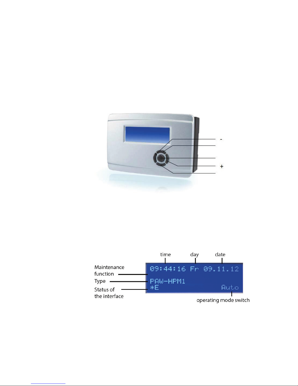
Models featuring a display offering a front panel that is highly intuitive and simple to
use, containing a backlit text display and a control element with 5 keys.
Fig. 1.2: The control elements
1.4.2 The default display
The display of HPM is a backlit text display of 4 x 20 characters. When the controller
is in “sleep mode” the “default display” will be shown, containing the following
information:
Fig. 1.3: The default display
The menu “global – service – display” permits adjusting the default display to the
individual needs of the user. The 4 rows of the display is capable of displaying current
sensor values, output signals and/or plain text.
UP
OK
DOWN
8
1.4.3 The main operating mode switch
The menu for the main operating switch can be accessed by pressing “+” while in the
default display. The menu contains the operating mode switch for the controller and
the main switch for the heat pump.
The position of the switch can then be selected by using “+” and “-”. The selected
position can be entered by pressing “OK”.
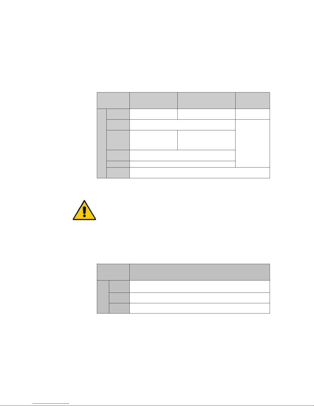
The main operating switch has the following effects on the module library:
Heating circuits Domestic hot water circuits Heat pump
Switch position
Off
Off: Valve stays in current
position, pump off
Off: Valve stays in current
position, pump off
Off
Auto
Automatic operation: Automatic setpoint switching depending
on timer program (day/night)
Automatic
operation:
Setpoint
according to
demand
Summer
Switch-off operation:
Valve closed, Pump off,
Frost protection remains
active
Automatic operation: Automatic
setpoint switch depending on
timer program
Holiday
Reduced operation/support operation: Setpoints of non-operating
time NO (night) apply
Duration
Nominal operation: Setpoints of operating time 1 OT1 day apply
Manual
Manual operation: Valve and pump function as defined in the “Manual operation”
menu
Table 1.4: Operating mode switch
NOTE:
In the “Off“ switch position, the frost protection and pump prerun/extended
running functions are not active!
You can find further information in the menu “configuration – switch – operating
mode switch“. When the controller is communicating via communication port with
the heat pump(s) you will find in this menu also the main switch of the heat pump
MS-HPx. These parameters substitute the ON/OFF keys of the heat pump and the
FORCE key in the operating unit in the heat pump.
MS-Px
Switch- position
Off
Heat pump is switched off
Auto
Heat pump is controlled by the controller HPMx
Force
Heat pump is switched on in emergency operation (E-heater inside is active).
Table 1.5: Main switch of heat pump
For more information please refer to the menu “Configuration – switch – heat pump
main switch”

9
1.4.4 System overview
To provide the user or technical personnel with a quick overview of the current
heating system, it is possible to enter a menu which will display the most relevant
parameters. These include operating and error status, setpoints, current values and
signals transmitted via the output terminals, as well as the option to adjust the
occupation time 1 and non-occupation time setpoints.
To enter the system overview menu, press “-“ while in the default display. The list of
parameters can then be scrolled through by pressing “DOWN”. For more information,
refer to the chapter “System overview”.
1.4.5 Overtime
It is possible to easily prolong the current occupation time without changing the basic
timer parameters, or to spontaneously initiate a new occupation time. This can be
performed simply by pressing “DOWN”. In the overtime menu, the overtime for each
consumer circuit (heating circuit 1, heating circuit 2 and the domestic hot water
circuit) can then be activated separately, depending on the current configuration of the
controller.
For more information, refer to the chapter “Configuration – keys”.
1.4.6 Maintenance / acknowledgment
To acknowledge errors of the heat pump(s) and to give a service technician the
possibility to service the pump(s) in question, this menu provides the possibility to
start the maintenance function (signalling demand to the heat pump for 15 minutes) or
to acknowledge/reset errors.
Pressing “UP” will bring up the Acknowledge/maintenance menu. The “DOWN” key
then permits selecting the desired parameter. The keys “+” and “-“you enables
adjusting the parameter to “ON” or “OFF”. The “OK” key is used to enter the
parameter setting.
For more information, refer to the chapter “Configuration – keys”.
10
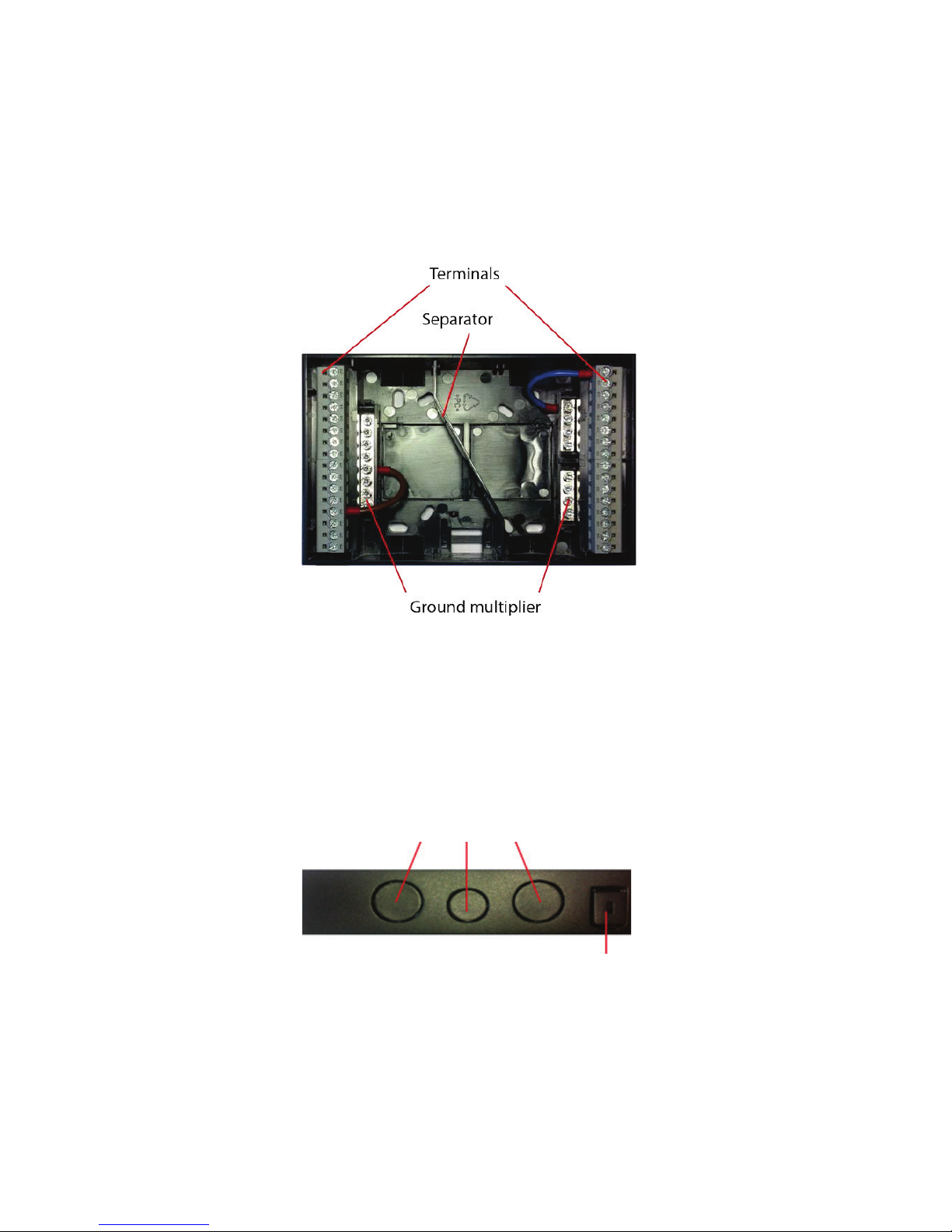
1.5 The socket
The socket of the HPM constitutes a separate component in which the terminals are
contained and the wires connected. The socket is divided by a separator into 2 parts.
The left-hand side contains low voltage connections, such as for sensors and 0...10 V
terminals, and the right-hand side contains high voltage connections (230 V) for
actuators and pumps.
Fig. 1.7: The socket
Each section of the socket contains ground multipliers, which are situated
immediately next to the terminals. Low voltage and high voltage use separate grounds
to prevent electromagnetic influence.
To fasten the socket to the controller, simply slide the controller onto the socket and
push the two clips on each side of the socket. A screwdriver is required in order to
open the clips again.
Fig. 1.8: Cable knockouts and clip to fasten the socket
The cable inlets must be pressed out where needed. The holes are prepared for
standard M-cable glands.
Cable inlets
Clip to fasten socket
11
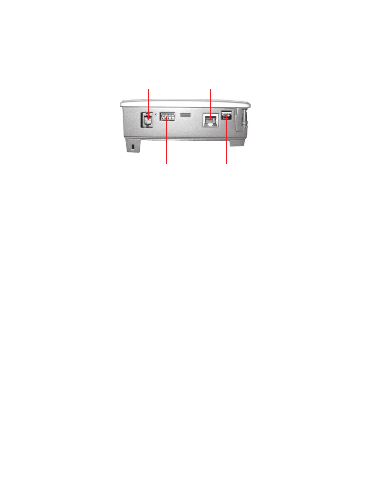
1.6 The interfaces
Depending on the type of controller, a number of interfaces are available:
Fig. 1.9: The interfaces
USB
Each controller is equipped with an USB interface. The USB interface can be used to:
x Make adjustments.
x Create a backup of the configuration.
x Upload backups or new firmware.
The only equipment neccessary is a normal USB-to-Micro-USB interface cable and
the necessary COM-port driver as required by the computer’s operating system.
External display (RS-485)
This interface enables connecting a remote control unit (e.g. an external touch panel).
Communication with the heat pump (RS-485)
This interface is used to communicate with the heat pump. To connect the heat pump,
a PAW-HPMINT-X model adapter cable is needed. The “X” stands here for either “–
U” (a 3 m adapter cable to communicate with the internal unit of a split-heat pump) or
“–M” (a 30 m adapter cable to communicate with a MONO-block-heat pump). In this
case, the HPM functions as a substitute for the operating unit of the heat pump.
Network (Ethernet)
If the controller is equipped with an Ethernet interface, it can be connected to a
communications network which can in turn be connected to the Internet. The interface
can be used to:
a) Communicate with the controller.
b) Connect master and slave controllers when using more than one heat pump in the
system.
RS-485 for
external display
Ethernet for TCP/IP (web
server) and other controllers
RS-485 for
communication with
heat pump
USB to PC
(service)

12
1.7 Technical data
Power supply ..........................................................................85...265 V AC, 50/60 Hz
Power consumption ..................................................Max. 8 VA (depending on model)
Dimensions......................................................................146.7 x 97.6 x 76.0 (WxHxD)
Ambient temperature .........................................................................................0...50°C
Storage temperature ..................................................................................... -40...+50°C
Ambient humidity ..................................................................................Max. 90 % RH
Protection class ...................................................................IP20 (mounted on the wall)
............................................................................................... IP40 (mounted in cabinet)
Connection ...................................................................................Terminals in a socket
Memory backup .................................................................Long life battery (>8 years).
....................................................... All settings are stored in the event of power failure.
Display ..........................................................Backlit, LCD, four rows of 20 characters
EMC emissions & immunity standards
This product conforms to the requirements of the EMC Directive 2004/108/EC
through product standards EN 61000-6-1:2001 and 61000-6-3:2001.
RoHS
This product conforms to the Directive 2011/65/EU of the European Parliament and
of the Council.
Inputs
Analogue inputs .... 8 x For Pt1000, NI1000 or NI1000LG sensors (accuracy ± 0.4°C).
...................................................................................Can also be used as digital inputs.
.............................................2 x 0...10 V DC (accuracy ± 0.15 % of full output signal).
Digital inputs ............................................. 2 x contact input for potential free contacts
Outputs
Analogue outputs .........................................2 x 0...10 V DC, 1 mA, short-circuit proof
Digital outputs ..........................7 x relay, 230 V AC, 1 A inductive. Totally max. 7 A.
Collective alarm .............................................................. The output can be configured
Interface
USB ......................................................... Service interface with micro USB connector
Web ..................................................... TCP/IP (with fixed IP, DHCP can be activated)
............................................................................................ Web graphic + WebRemote
Bus ...............................................Communication with a heat pump via adapter cable:
For Split- heat pumps ................................................. PAW-HPMINT-U (3 m long)
For MONO-block heat pumps..................................PAW-HPMINT-M (30 m long)
External display..................................... RS-485 for the connection of a Touch-Display
................................................................as remote control unit, with room temperature
........................................................................................sensor and setpoint adjustment
13
Chapter 2 Installation and wiring
2.1 Installation
HPM comes prepared for 3 different kinds of mounting.
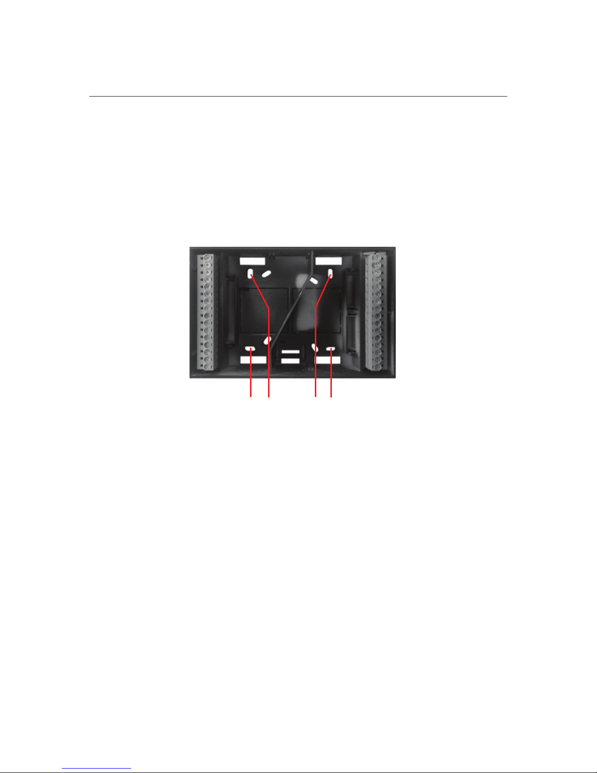
2.1.1 Wall mounting
Fig. 2.1 Wall mounting
Because the HPM is a stand-alone controller, it is highly suitable for direct wall
mounting. The socket comes equipped with specially located holes that enables it to
be screwed directly onto the wall.
Holes for wall mounting
14
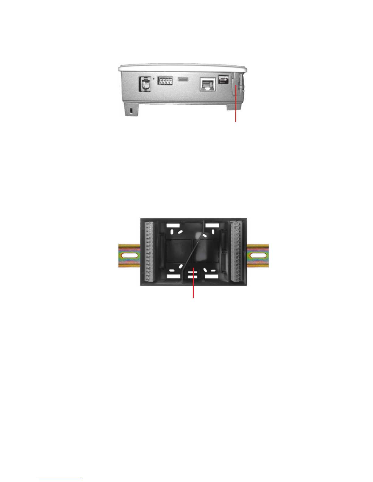
2.1.2 Mounting in a control cabinet door
Fig. 2.2 Control cabinet door mounting
The HPM can be installed in a cabinet door or in a panel of a boiler or a heat pump.
The controller is designed to fit into a standard hole of 138 x 192 mm. Simply slide
the controller through the hole in the cabinet door or the boiler (heat pump) panel and
turn the flaps until the controller is secured. No screwdriver or additional tools are
needed.
2.1.3 Mounting in control cabinet on DIN-rail
Fig. 2.3 Mounting on DIN-rail
The socket of the HPM is also ready for direct mounting onto a DIN-rail, either inside
of a cabinet or in any other housing in which a DIN-rail is available. Simply clip the
socket onto the DIN-rail and the mounting process is completed.
Flaps for fastening
controller in cabinet door
Lock for DIN-rail
15
2.2 Wiring
2.2.1 General
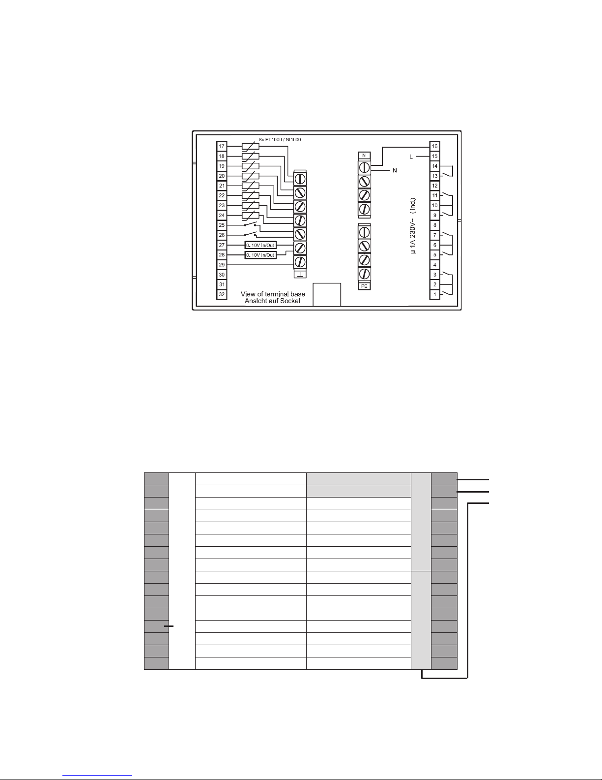
Fig. 2.4: Connection of power supply, relay outputs, sensor and contact inputs.
The HPM is equipped with 7 potential-free relay outputs, 8 sensor inputs (which can
also be used as contact inputs), 2 contact/pulse counter inputs and 2 continuous
(0…10 V) universal inputs/outputs.
The following chapters explain the use of the terminals more thoroughly.
2.2.2 Main voltage
17
Sensor ground
Sensor
N
N
16
18
Sensor
L
15
19
Sensor
Potential for 13
14
20
Sensor Relay
13
21
Sensor Not used
12
22
Sensor
Relay
11
23
Sensor Potential for 9+11
10
24
Sensor Relay
9
25
Contact / counter
Not used
PE
8
26
Contact / counter Relay
7
27
0…10 V Potential for 5+7
6
28
0…10 V Relay
5
29
Sensor ground
Not used
4
30
Not used Relay
3
31
Not used Potential for 1+3
2
32
Not used
Relay
1
Fig. 2.5: Connection of the power supply
The HPM is a stand-alone controller with a 230V power supply. The power supply
also feeds the components, which in turn are connected to the relays.
N
L 230 V AC
PE
 Loading...