

Panasonic PAW560MAH2L, PAW560MAH2, PAW280PAH2L, PAW280PAH2, PAW280MAH2L Installation Instructions Manual
...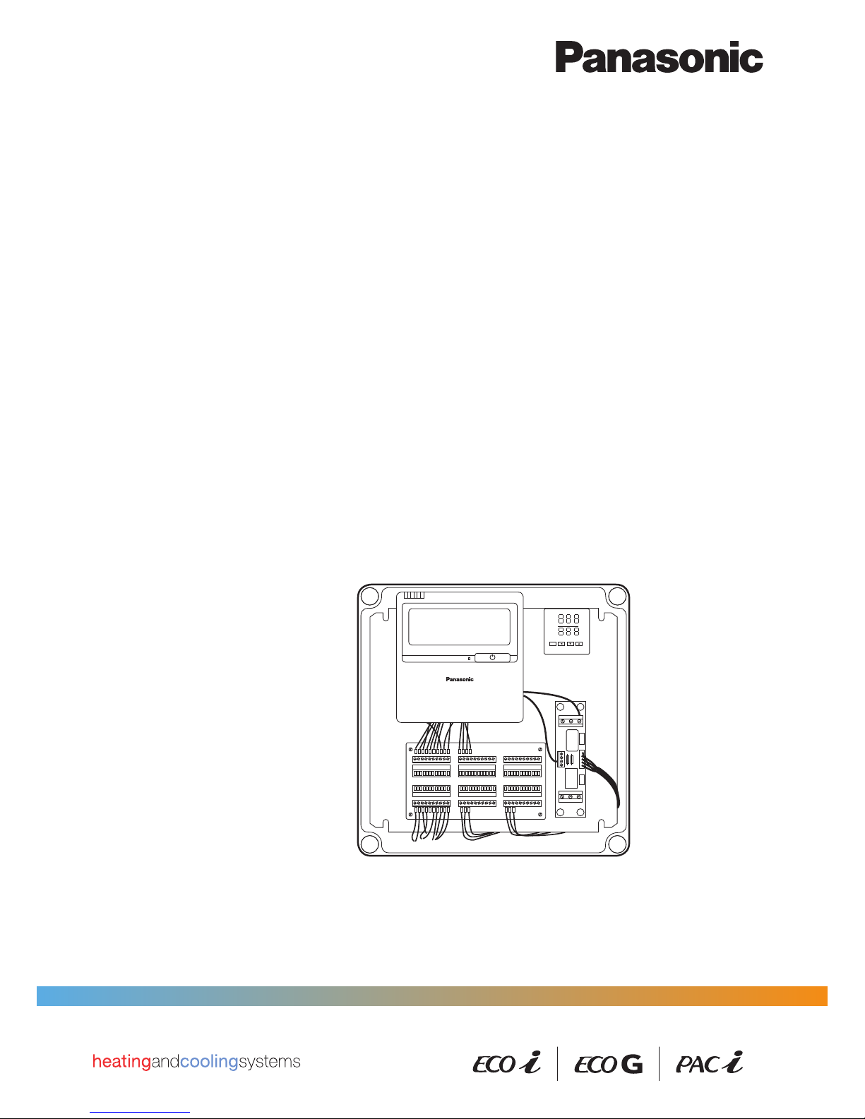
Air Handling Unit Kit
Installation Instructions
SET
AL1
OUT
ATU
PV
SV
ºC
ºC


3
Air Handling Unit Kit
Installation Instructions
Original Installation Instructions (English)
Preliminary version as at December 2014
COPYRIGHT
© Panasonic Marketing Europe GmbH 2014. All rights reserved.
.

4
Table of Contents
1 General information and safety instructions .................................................... 6
1.1 Introduction ......................................................................................................................... 6
1.2 Structure and meaning of notices and symbols .............................................................. 7
1.3 Safety instructions .............................................................................................................. 8
1.4 Warranty policy ................................................................................................................... 9
2 Ventilation theory and air handling units .......................................................... 10
2.1 Purpose of air-conditioning ............................................................................................... 10
2.2 Purpose of ventilation ........................................................................................................ 10
2.3 Mechanical ventilation systems ........................................................................................ 12
2.4 Air handling units ................................................................................................................ 13
3 Product description ............................................................................................. 17
3.1 General description ............................................................................................................ 17
3.2 Scope of supply .................................................................................................................. 17
3.3 System lineup ...................................................................................................................... 20
3.4 AHU Kit dimensions and exterior view ............................................................................. 21
3.5 Wiring layout ....................................................................................................................... 23
3.6 AHUKitenclosureconguration ....................................................................................... 27
3.7 System Overview ................................................................................................................ 28
3.8 Technical data and limitations ........................................................................................... 32
4 Installation ............................................................................................................ 37
4.1 Installation of AHU Kit ........................................................................................................ 37
4.2 Installation of refrigerant piping ........................................................................................ 40
4.3 Installation of expansion valve .......................................................................................... 41
4.4 Installation of thermistors .................................................................................................. 42
4.4.1 Installation of thermistor on gas pipe ........................................................................ 43
4.4.2 Installation of thermistor on liquid pipe ..................................................................... 45
4.4.3 Installation of thermistor on heat exchanger pipe middle ......................................... 46
4.4.4 Installation of thermistor for suction and discharge air stream ................................. 47
4.5 Disconnection of jumper on outdoor unit PCB ................................................................ 47
5 Electrical Wiring ................................................................................................... 49
5.1 General precautions on wiring .......................................................................................... 49
5.2 Recommended wire lengths and diameters ..................................................................... 50
5.3 Wiring system diagrams ..................................................................................................... 51
5.4 Terminal block layout ......................................................................................................... 54
5.5 Connection of wiring to terminals ..................................................................................... 55

5
5.6 Connection of external signal lines................................................................................... 57
5.7 Electric circuit examples .................................................................................................... 59
6 Test Run ................................................................................................................ 60
7 Control .................................................................................................................. 61
7.1 Remote controller ............................................................................................................... 61
7.2 Thermostat........................................................................................................................... 61
7.2.1 Control and display elements ................................................................................... 61
7.2.2 Operation .................................................................................................................. 62
7.2.3 Initial Settings ........................................................................................................... 67
7.2.4 Error Codes .............................................................................................................. 72
7.2.5 Maintenance and Service ......................................................................................... 72
7.2.6 Technical data ........................................................................................................... 73
6
General information and safety instructions
1 General information and safety instructions
1.1 Introduction
This document contains the installation instructions for the Panasonic AHU Kits.
The following products are covered in this documentation:
● PAW-160MAH2 / PAW-160MAH2L
● PAW-280MAH2 / PAW-280MAH2L
● PAW-560MAH2 / PAW-560MAH2L
● PAW-280PAH2 / PAW-280PAH2L
AHU Kits connect Panasonic ECOi, ECO G and PACi outdoor units to third-party air handling
unit systems, using the same refrigerant circuit as the VRF system.
Application examples for Panasonic AHU Kits are hotels, ofces, server rooms or all large buildings where air quality control such as humidity control and fresh air is needed.
The installation should be performed only by qualied electricians in strict accordance with the
installation instructions and especially with the safety instructions given in this document.
Where information in this document does not apply to all three VRF system ranges, but only to
either ECOi, ECO G or PACi systems, this will be indicated by the relevant product range logos:
Important: Validity of this document
Due to the ongoing development and innovation of Panasonic products, this document and all
the information contained herein is preliminary (as at December 2014). It may not reect the
current status of the relevant products. Preliminary or missing information will be updated and
added on an ongoing basis and published at the discretion of Panasonic.
i
7
General information and safety instructions
1.2 Structure and meaning of notices and symbols
Safety notices
WARNING
This indicates a hazardous situation which, if not avoided, could result in death or serious injury.
CAUTION
This indicates a hazardous situation which, if not avoided, could result in minor or moderate
injury.
NOTICE
This indicates a hazardous situation which, if not avoided, could result in property damage.
Other notices
Important
This indicates other important information or references to other useful sources of technical data
and descriptions.
!
i
8
General information and safety instructions
1.3 Safety instructions
WARNING
The following precautions need to be followed strictly, in order to avoid hazardous situations,
which could result in death or serious injury.
Electricshockorremayresultfrominadequateorincorrectinstallationorwiring
procedures.
► System installation must only be performed by an experienced electrician.
► Arrange installation at the dealer where the system was purchased or use a
professional installer.
► System installation must be performed in strict accordance to the installation
procedures described in this document.
Damagetothecircuitbreakersmayresultfromincorrectelectricalwiring,insufcient
electrical circuit capacity or use with other electrical devices.
► Always use a dedicated branch circuit for electrical wiring.
► Strictly avoid using other electrical devices within the same electrical circuit.
► Make sure the electrical circuit used has sufcient capacity.
Overheatingorremayresultifconnectionsorattachmentsarenotsecure.
► Use the specied cables (type and wiring diameter) for the electrical connec-
tions, and securely connect the cables.
► Run and fasten the cables securely so that external forces or pressure placed
on the cables will not be transmitted to the connection terminals.
Suffocation can result if refrigerant gas leaks and exceeds the limit density in a small
room.
► Installation of the refrigerant piping must only be performed by an experienced,
qualied installer to minimize the risk of leaks.
► Install so that even if refrigerant gas leaks into the room, it will not exceed the
limit density of 0.44 kg/m3, in accordance with the local regulatioins for facility
air conditioning equipment.
► If the refrigerant gas concentration does exceed the limit density, do one of the
following:
● install an opening in a neighbouring room
● or install ventilation equipment triggered by gas leak detection sensors
● or install an automatic pump-down system provided by the manufacturer of
the equipment
Poisonousgascanresultifrefrigerantgascomesintocontactwithre.
► After installation of refrigerant pipes, perform a dry nitrogen gas sealing test to
check that there are no leaks.
► Ventilate the work area if refrigerant gas leaks during installation.

9
General information and safety instructions
► Prevent the refrigerant gas from coming into contact with a fan heater, stove,
range, or other source of re.
Incorrectinstallationcanresultinfallingequipmentcausingdamage,injuriesorother
accidents.
► Install in a location that is fully strong enough to support the weight of the
equipment.
► Perform installation that is secure enough to withstand earthquakes, whirlwinds,
storms and other strong winds.
Frostbite injuries may result from coming into direct contact with the refrigerant gas.
► When handling refrigerant gas, be careful not to touch the refrigerant gas
directly.
CAUTION
The following precautions need to be followed strictly, in order to avoid hazardous situations,
which could result in minor or moderate injury.
Electricshock,shockandresmayresultfromincompletegroundingoftheequipment
or failure to install an earth leakage breaker.
► Be sure to ground equipment properly.
► Do not attach ground wires to gas pipes, water pipes, lightning arresters, or
telephone ground lines.
► Always install an earth leakage breaker.
Ignitionofammablegasorinammablematerialsmayresultfrominstallingthesystem
inlocationswhereammablegascangenerate,enter,buildup,orleak.
► Do not install the system in locations where ammable gas can occur in any
way.
► Do not install in locations where volatile inammable materials are handled.
1.4 Warranty policy
We can be held responsible for the quality and performance of the AHU Kit we supply.
However, we cannot be held responsible for the performances, operations and machine controls
of your complete AHU system which incorporates our AHU Kit, nor for the components used in
the refrigerant cycle of your AHU system (including, but not limited to, compressors, high-pressure switches, check valves, strainers, expansion valves, solenoid valves, 4-way valves, capil-
lary tubes, accumulator tanks, and heat exchanger tubes), nor for any damages and defects
caused in the process of installing our AHU Kit, by the system design and/or during assembly of
your AHU system.
We do not publish the certicate to show conformity to the EMC and the product safety requirements applicable to your complete AHU system.
10
Ventilation theory and air handling units
2 Ventilation theory and air handling units
2.1 Purpose of air-conditioning
The purpose of air-conditioning is to provide comfortable indoor air conditions for the room occupants and to provide energy saving potentials for the owner.
Comfort
If room occupants feel “comfortable“ in a given room, depends mainly on the following two
factors:
● air temperature
● relative air humidity
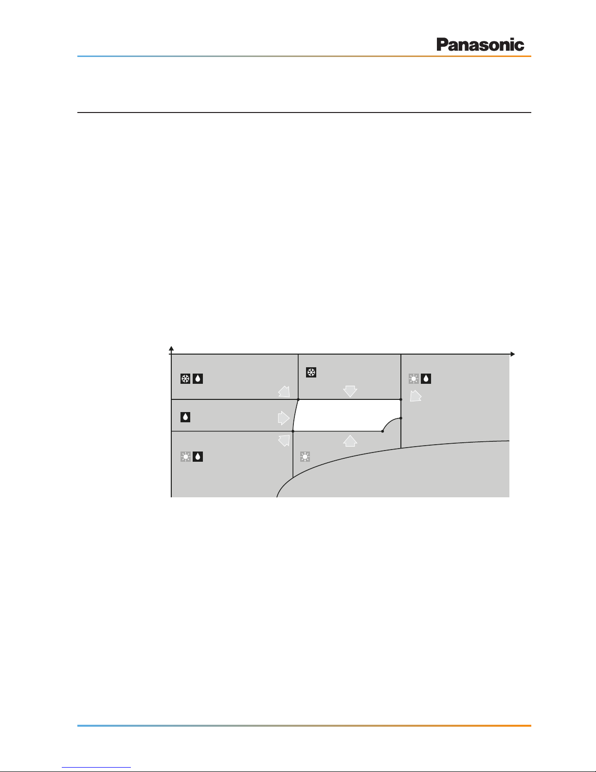
However, optimum working or living conditions do not only exist at a specic setpoint of room
temperature and room humidity, but also within a certain band width of the setpoint.
A temperature setpoint of 22 °C and a relative humidity setpoint of 45 % with variations of ±2 °C
and ±15 %rh respectively are typical levels used for ofce spaces. Also, at high temperatures,
maximum limitation of absolute humidity should be provided to avoid “muggy” conditions. Typically, this limit value lies at about 10 g/kg (H2O).
Absolute humidity
rh = relative humidity
Temperature
Cooling and
humdifying
Heating and
humdifying
Humdifying and
reheating, if required
Humdifying only
Comfort range
35 %rh
24 °C
20 °C
65 %rh
Cooling only
Heating only
Energy savings
Besides the advantages in terms of indoor air quality, air conditioning offers also an energy saving potential. For example, while uncontrolled ventilation through open windows leads to large
amounts of heat being lost to the outside during the heating season or gained from the outside
during the cooling season, air conditioning systems provide possibilities to utilize the extra “free”
energy in heat recovery modules so that overall operating costs will be reduced.
The larger the area of the comfort range, the better the energy saving opportunities.
2.2 Purpose of ventilation
The purpose of ventilation is to introduce fresh air from outside into a building or room, in order
to control indoor air quality and thermal comfort.
11
Ventilation theory and air handling units
Ventilation demands
Ventilation must meet the following demands:
● Provide outside air (oxygen) for breathing
● Control of indoor air contaminants
● Covering of the building’s thermal loads (temperature and humidity control)
● Setting of uniform conditions in the occupied zone
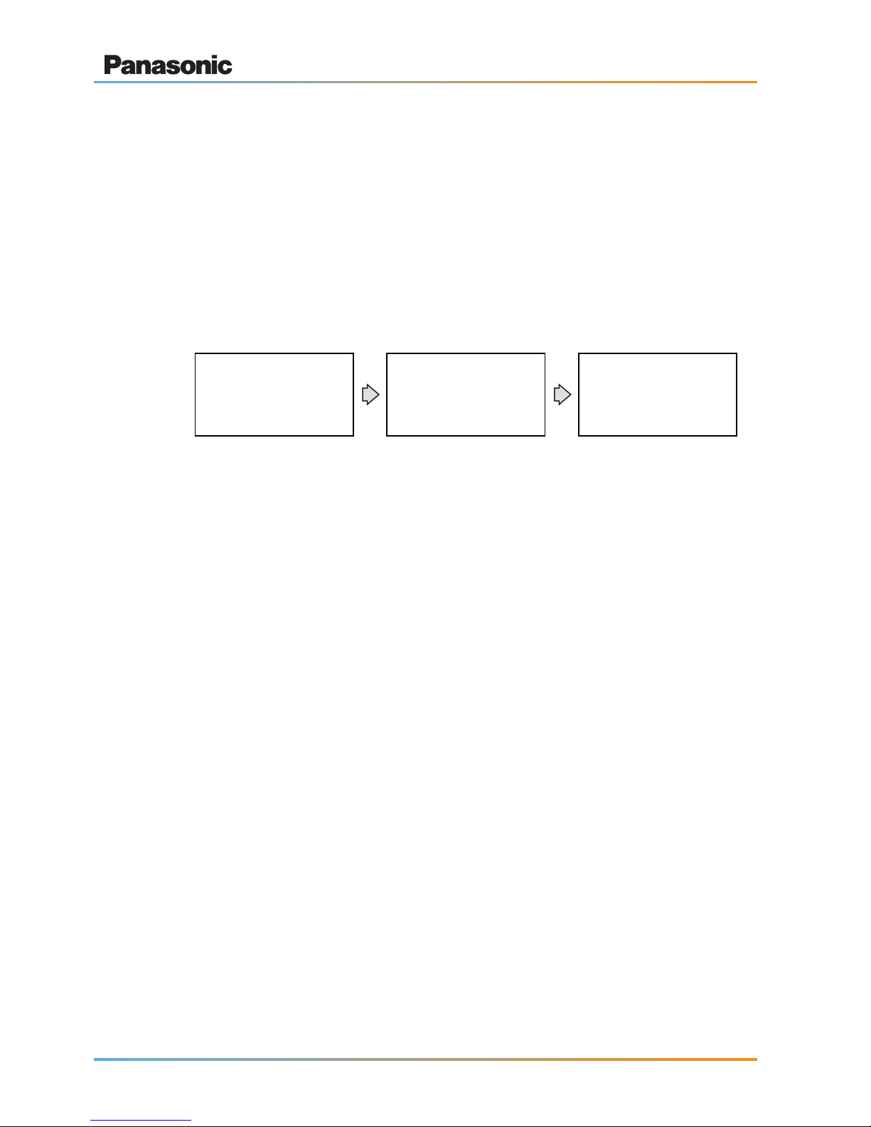
As the outside or ambient air varies in temperature, humidity, contamination etc., it must be specically conditioned before being supplied to the target room, so that it meets the dened indoor
air requirements. “Conditioning” means treating the ambient air by ltering, heating, cooling,
humidifying, dehumidifying etc.
Room with defined requirements:
· Temperature
· Humidity
· Pressure
· Ventilation
Return airSupply air
While the conditioned air (supply air) is being introduced to the building or room, return air,
which no longer meets the dened indoor air requirements (e.g. in terms of temperature or humidity) is withdrawn from the room and rejected to the outside.
Thus, a constant indoor air exchange is maintained by the mechanical ventilation system.
Recommendedindoorairrequirements
Organizations concerned with setting quality standards for the HVAC industry (Heating, Ventila-
tion and Air Conditioning), like e.g. ASHRAE or Eurovent, give recommendations for indoor air
quality criteria depending on the intended use of the room.
The ASHRAE recommendations for residential and commercial applications are as follows:
● Temperature: ranging from 20 to 24 °C
● Humidity: ranging from 35 to 65 %rh
● Pressure: slightly positive pressure to reduce outside air inltration
● Ventilation: ranging from 4 to 8 complete air changes per hour
In order to full the ventilation demands and to meet the recommended indoor air requirements,
mechanical ventilation systems comprising air lters, supply and return air ventilators, cooling
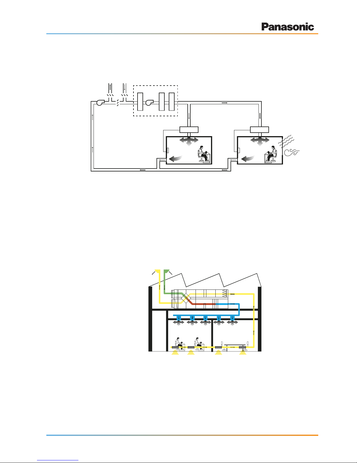
12
Ventilation theory and air handling units
and heating coils, variable air volume (VAV) valves, thermostats and other air-handling equipment are used.
Exhaust
air
Outside
air
Dampers
Air handling unit (AHU)
Supply
air fan
Return
air fan
Return air
Filter
Cooling
Heating
Solar
radiation
Wind
ThermostatThermostat
VAV valve VAV valve
2.3 Mechanical ventilation systems
Main components of mechanical ventilation systems
The main components of a mechanical ventilation system are the following:
● Air handling unit (AHU)
● Air ducts
● Air distribution elements
Supply air
Outside air
Return air
Exhaust air
Types of mechanical ventilation systems
Mechanical ventilation systems can be subdivided based on the pressure relation between the
ventilated space and the ambient environment.
13
Ventilation theory and air handling units
In most cases, the pressure in ventilated spaces is equal to the atmospheric pressure of the
outside. This means that the air-ow delivered to a space equals the airow brought back from a
space. Such spaces are described as neutral or balanced.
However, in mechanical ventilation systems the supply air and return air ows might be
sized differently, when necessary. In these cases, a building can be either pressurized or
depressurized:
● Pressurized:
The pressure within the ventilated space is positive (higher) compared to the
outside pressure. This means, a certain amount of air is exltrated from the
space through openings and cracks.
Examples are clean rooms, operation theatres etc.
● Depressurized:
The pressure within the ventilated space is negative (lower) compared to the
outside pressure. This means, a certain amount of air is inltrated to the space
through openings and cracks.
Examples are kitchens, toilets, laboratories working with toxic substances etc.
2.4 Air handling units
Main components of air handling units
The main components of an air handling unit are shown in the following graphic.
Mixed air (MA)
Supply air fan
(SAF)
Supply air
(SA)
Outside air
(OA)
Return air
(RA)
Exhaust air
(EA)
Dampers
(D)
Dampers
(D)
Dampers
(D)
Cooling Coil
(CC)
Heating Coil
(HC)
Air handling unit (AHU)
Filter
(F)
Recirculated
air (CA)

14
Ventilation theory and air handling units
Air handling units can be manufactured targeted at the specic purpose for which they will be
used. Possible features comprise, but are not limited to the following non-exhaustive list of
characteristics:
● Construction: monoblock or split in separate delivery sections
● Installation location: indoor, outdoor
● Execution: horizontal, vertical, double deck or side-by-side
● Design: e.g. standard, hygienic, explosion-proof or anti-grease
● DX coil: with or without (see below the example of an AHU system with DX coil)
● Heat recovery: with or without
● Size: ranging from 150 m3/h to 100000 m3/h
● Applying European standards: EN1886; EN13053
RA
EA
OA
SA
Casing
HumidifierAir filterDamper
Sirocco fan
Air flow DX coil
Turbo fan
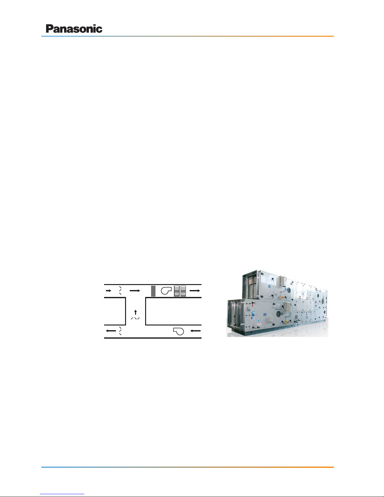
Main types of air handling units
Supply type
Exhaust type
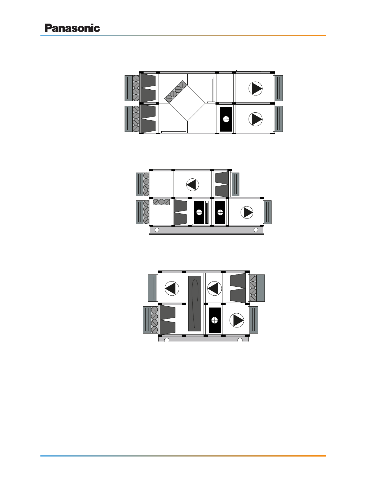
15
Ventilation theory and air handling units
Supply/Exhausttypewithcross-owheatexchanger
Supply/Exhaust type with mixing chamber
Supply exhaust type with rotary heat exchanger
16
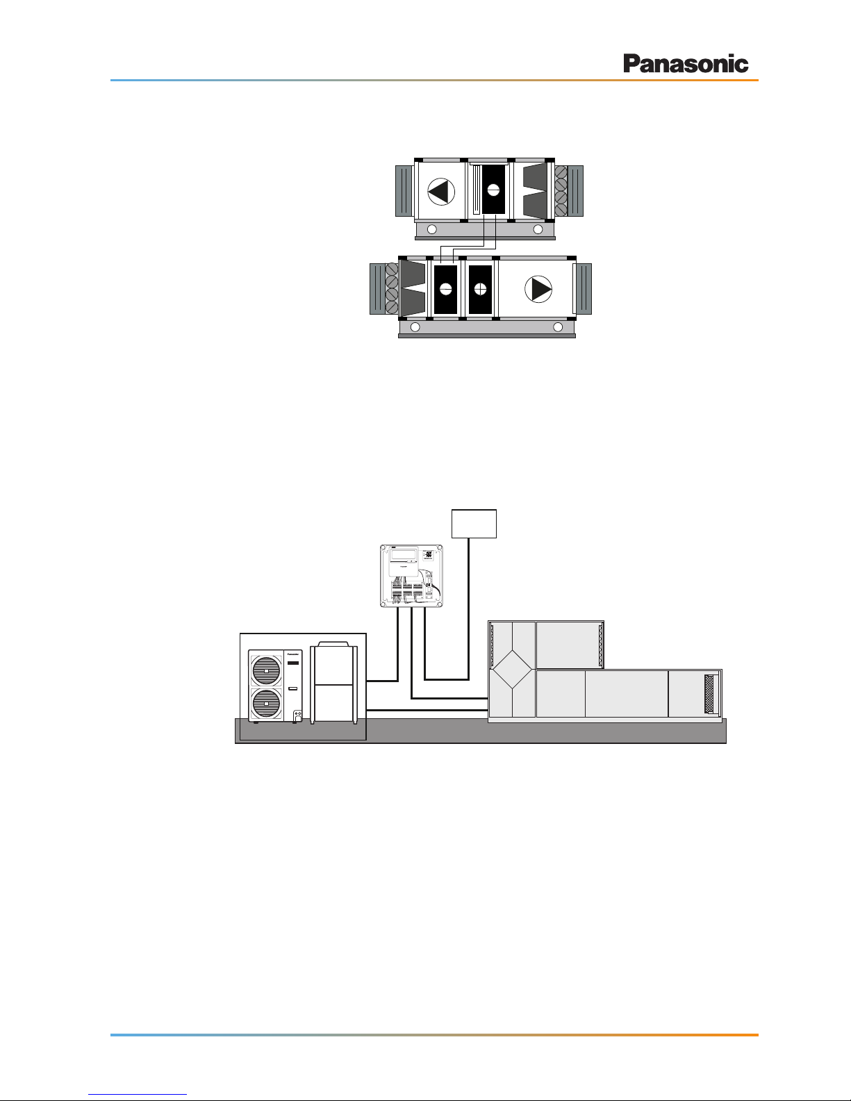
Ventilation theory and air handling units
Supply/Exhaust type with glycol heat exchanger
Connecting AHU systems via the AHU Kit to ECOi/ECO G or PACi outdoor
units
The following graphic shows an example for connecting a third-party air handling unit via the
Panasonic AHU Kit to Panasonic ECOi/ECO G or PACi outdoor units.
PACi or ECOi/ECO G outdoor unit
Demand control on the outdoor unit
managed by external 0–10 V signal
Air Handling Unit (AHU)
AHU control kit
External BMS
0 – 10V capacity control
1 This schematic layout applies to the advanced AHU Kit version only, because it features an in-built CZ-CAPBC2
interface handling the 0–10 V control. This enables two control alternatives:
● Capacity control through external BMS via 0–10 V signal
● Capacity control through in-built supply air or ambient temperature sensor
2 As the “light” version of the AHU Kit does not include an in-built CZ-CAPBC2 interface for handling the 0–10 V con-
trol, this schematic layout does not apply to the “light” AHU Kit version.

17
Product description
3 Product description
3.1 General description
AHU Kits connect Panasonic ECOi, ECO G and PACi outdoor units to third-party air handling
unit systems, using the same refrigerant circuit as the VRF system.
Application examples for Panasonic AHU Kits are hotels, ofces, server rooms or all large buildings where air quality control such as humidity and temperature control and fresh air is needed.
The Panasonic AHU Kits offer a wealth of connectivity possibilities so that they can be easily
integrated into many systems.
The new AHU Kit has been developed to better meet customer demand:
● Two versions available depending on the required functionality (light or advanced version)
● IP65 enclosure providing the possibility for outdoor installation
● 0–10 V demand control (included on the CZ-CAPBC2 interface)*
● Easy control by BMS
* Only available with ECOi and PACi Elite units from 6 kW up to 14 kW (for PACi Elite units from 20/25 kW available
on request)
Featuresandbenets
● The system is controlled by the air intake (or room return air) temperature in the
same way as a standard indoor unit. Selectable modes: Automatic / Cooling /
Heating / Fan / Dry (equivalent to Cooling).
● Easy integration into BMS or AHU control systems using demand control: 40 to
115 % (5 % steps) of nominal current by 0–10 V input signal (advanced version
only)
● Room supply air temperature can be controlled by the additional thermostat, its
supply air temperature sensor and the 0–10 V input signal for enhanced comfort
and efciency (advanced version only).
● Target temperature setting based on ambient temperature with CZ-CAPBC2
using 0–10 V signal (advanced version only).
● Connectable with P-LINK system.
● Fan control signal from the PCB can be used for controlling the air volume of an
external fan (High/Mid/Low and LL for Th-OFF). (Need to change the fan control
circuit wiring at eld.)
● Defrost operation signal, Thermo-ON/OFF states output
● Drain pump control (Drain-pump and the oat switch to be supplied in local)
● Basic humidier control output (humidier eld supplied)
● Alarm and operation output
3.2 Scope of supply
The AHU Kits are supplied in two versions, “light” or “advanced”, and can be selected based on
the required functionality.

18
Product description
The light version, denominated by the letter “L” in the model name, contains the following
components:
● IP65 case
● Control unit including transformer
● Relays
● Terminal boards
● Remote controller (CZ-RTC2)
● PCBs for the expansion and RAP valves
● PCB for T10 connection (PAW-T10)
● Expansion valve (only for ECOi and ECO G)
● Refrigerant temperature sensors (E1, E2/E3)
● Air intake and air outlet temperature sensors (TA, BL)
In addition to this, the advanced version, without the letter “L” in the model name, contains also
the following components:
● Thermostat including an additional temperature sensor to be used either for
room supply air or ambient air temperature
● Interface for 0–10 V control (CZ-CAPBC2)
The heat exchanger, fan and fan motor must be eld supplied.
Control functions provided as standard by integral components
CZ-RTC2 Timer remote controller
● Operation-ON/OFF
● Mode selection
● Temperature setting
● Parameter settings
Additional Thermostat (advanced version only)
● Target temperature setting based on ambient temperature with proportional
integral logic*
● Demand control based on room supply air temperature to enhance comfort and
efciency*
* Only one of these two options can be chosen at a time.

19
Product description
CZ-CAPBC2 Mini seri-para I/O unit (advanced version only)
● Easy integration in external AHU control systems and BMS
● Demand control: 40 to 115 % (5 % steps) of nominal current by 0–10 V input
signal*
● Target temperature setting by 0–10 V or 0–140 Ω input signal*
● Room supply air temperature output by 4–20 mA signal
● Mode select or/and ON/OFF control
● Fan operation control
● Operation status output/ Alarm output
● Thermostat ON/OFF control
* Demand control by external BMS cannot be combined with the demand control or target temperature setting accom-
plished by the thermostat. However, if simultaneous demand control and target temperature setting is needed, this
can only be achieved by using a second (optional) CZ-CAPBC2 interface.
PAW-T10 PCB to connect to T10 connector
● Dry contact PCB for easy control of the unit
● Operation ON/OFF input signal
● Remote control prohibition
● Operation ON status output signal, maximum 230 V / 5 A (NO/NC)
● Alarm status output signal, maximum 230 V / 5 A (NO/NC)
PAW-OCT, DC12 V outlet, OPTION terminal
● Output signal for Cooling/Heating/Fan status
● Output signal for Defrost operation indication
● Output signal for Thermostat-ON status
Additional contacts available
● External humidier control (ON/OFF) 230 V AC 3 A
● External fan control (ON/OFF) 12 V DC
● External lter status signal potential free
● External oat switch signal potential free
● External leakage detection sensor or TH. OFF contact potential free (possible
usage for external blow out temperature control)
20
Product description
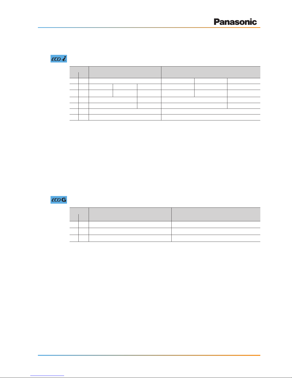
3.3 System lineup
System lineup – ECOi systems
Capacity Outdoor unit combination AHU Kit combination
HP kW
5 16 all ECOi outdoor units PAW-160MAH2(L)
1
– –
10 28 U-10ME1E81 – – PAW-280MAH2(L)
2
– –
20 56 U-20ME1E81 – – PAW-560MAH2(L)
3
– –
30 84 U-16ME1E81 U-14ME1E81 – PAW-560MAH2(L) PAW-280MAH2(L) –
40 112 U-20ME1E81 U-20ME1E81 – PAW-560MAH2(L) PAW-560MAH2(L) –
50 140 U-18ME1E81 U-16ME1E81 U-16ME1E81 PAW-560MAH2(L) PAW-560MAH2(L) PAW-280MAH2(L)
60 168 U-20ME1E81 U-20ME1E81 U-20ME1E81 PAW-560MAH2(L) PAW-560MAH2(L) PAW-560MAH2(L)
1 PAW-160MAH2(L):
● PAW-160MAH2(L) can be installed in combination with all ECOi 2-pipe and 3-pipe outdoor units like
any other standard indoor unit.
● Mixed installation with standard indoor units is possible. However, in this case one additional RAP
valve (CZ-P160RVK2) must be installed in the unit connection pipe, unless the unit is exclusively
used in cooling only operation.
2 PAW-280MAH2(L):
● Mixed installation with standard indoor units is possible. However, in this case two additional RAP
valves (2 x CZ-P160RVK2) must be installed in the unit connection pipe, unless the unit is exclusively used in cooling only operation.
● Connection to ECOi 3-way systems is not allowed.
3 PAW-560MAH2(L):
● Mixed installation with standard indoor units is not allowed.
● Connection to ECOi 3-way systems is not allowed.
System lineup – ECO G systems
Capacity Outdoor unit AHU Kit
HP kW
5 16
all ECO G outdoor units
PAW-160MAH2(L)
1
10 28
all ECO G outdoor units
PAW-280MAH2(L)
2
20 56 U-20GE2E5 PAW-560MAH2(L)
3
1 PAW-160MAH2(L):
● PAW-160MAH2(L) can be installed in combination with all ECO G outdoor units like any other stand-
ard indoor unit.
● Mixed installation with standard indoor units is possible. However, in this case one additional RAP
valve (CZ-P160RVK2) must be installed in the unit connection pipe, unless the unit is exclusively
used in cooling only operation.
2 PAW-280MAH2(L):
● PAW-280MAH2(L) an be installed in combination with all ECO G outdoor units like any other stand-
ard indoor unit.
● Mixed installation with standard indoor units is possible. However, in this case two additional RAP
valves (2 x CZ-P160RVK2) must be installed in the unit connection pipe, unless the unit is exclusively used in cooling only operation.
3 PAW-560MAH2(L):
● With PAW-560MAH2(L), only 1-to-1 installations are allowed (1 x U-20GE2E5 + 1 x PAW-
560MAH2(L)). Combinations with more than 1 outdoor unit or more than 1 AHU Kit are not possible.
● Mixed installation with standard indoor units is not allowed.
● Connection to ECO G 3-way systems is not allowed.
21
Product description
System lineup – PACi systems
Capacity
(kW)
Outdoor unit
1
AHU Kit
PACi Standard PACi Elite
Single-phase units Three-phase units Single-phase units Three-phase units
5.0 – – U-50PE1E5 –
PAW-280PAH2(L)
2
6.0 U-60PEY1E5 – U-60PE1E5A –
7.1 U-71PEY1E5 – U-71PE1E5A U-71PE1E8A
10.0 U-100PEY1E5 U-100PEY1E8 U-100PE1E5A U-100PE1E8A
12.5 U-125PEY1E5 U-125PEY1E8 U-125PE1E5A U-125PE1E8A
14.0 – U-140PEY1E8 U-140PE1E5A U-140PE1E8A
20.0 – – – U-200PE1E8
25.0 – – – U-250PE1E8
1 With PACi systems, only 1-to-1 installations are allowed (1 x PACi outdoor unit + 1 x PAW-280PAH2(L)). Combina-
tions with more than 1 outdoor unit or more than 1 AHU Kit are not possible.
2 Mixed installation with standard indoor units is not allowed.
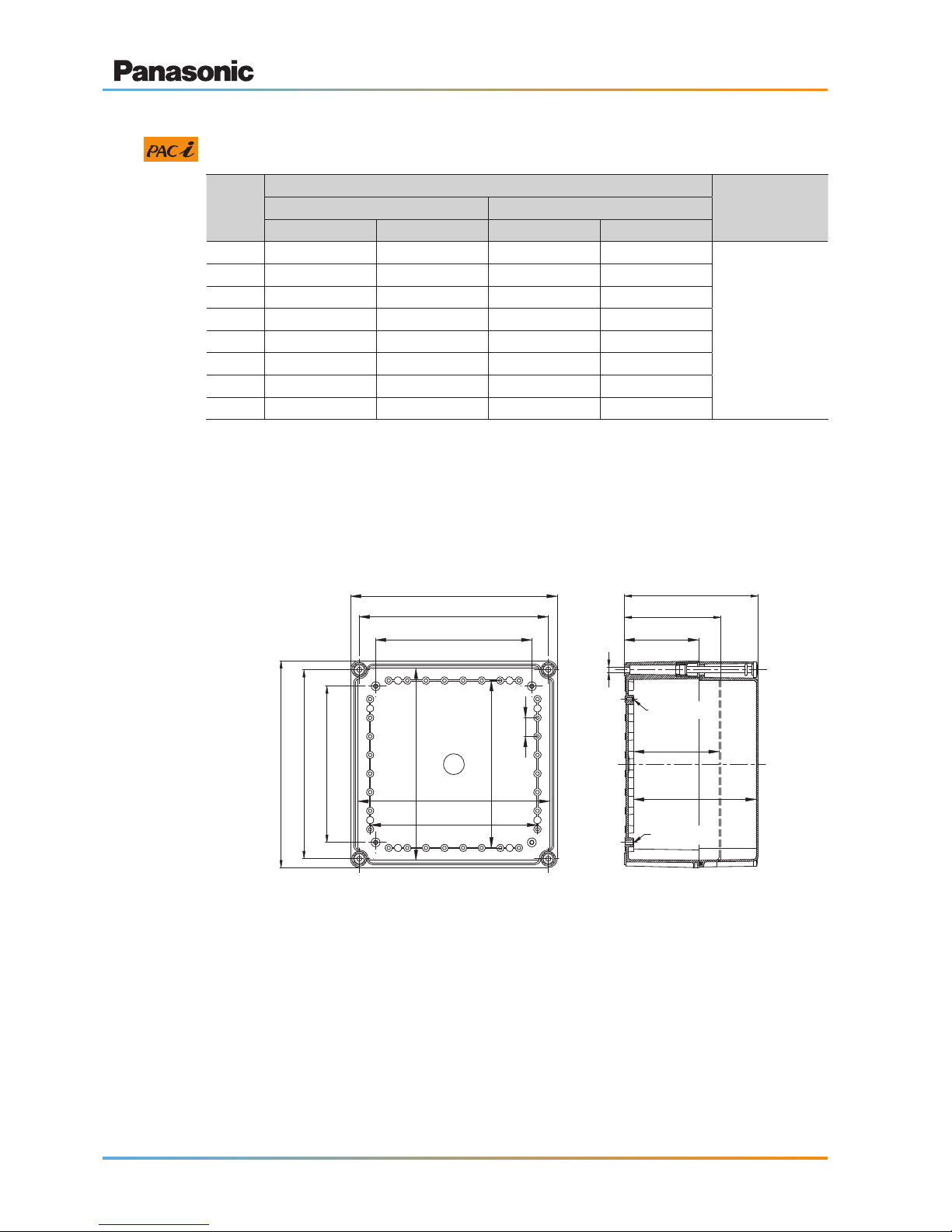
3.4 AHU Kit dimensions and exterior view
AHU Kit dimensions
Side view
210
254
278
210
254
278
225
257
225
257
100
130
180
165
115
Ø4.2 x 10
Ø5.2 x 11
25
Ø7
Front view (transparent cover removed)
22
Product description
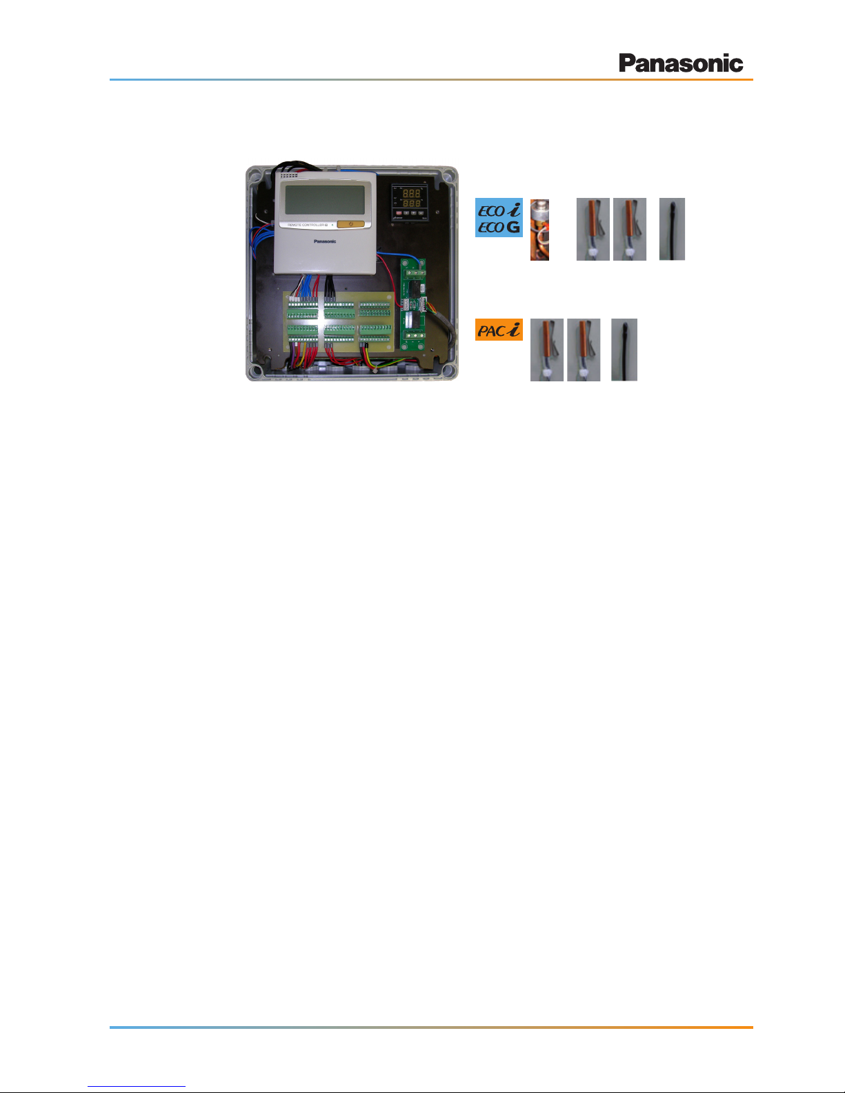
Exterior view of the AHU Kit
AHU Kit including
PCB, power transformer, terminal block
Expansion
valve
Thermistor x2
(Refrigerant: E1, E2)
Thermistor x2
(Refrigerant: E1, E3)
Thermistor
(Air: TA)
Thermistor x2
(Air: TA, BL)
Note: AHU Kit shown with transparent front cover removed.
23
Product description
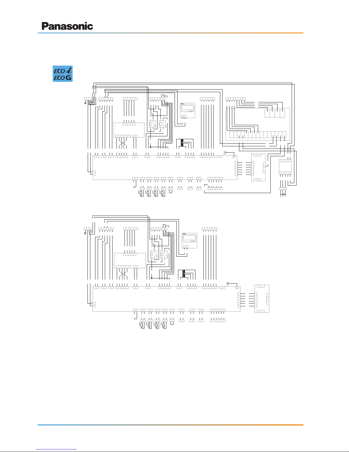
3.5 Wiring layout
Wiring layout – ECOi and ECO G systems
1
3
AC IN
(BLK)
1
2
OC
(BLU)
1
3
RC
(BLU)
1
2
EXCT
(RED)
1
2
3WAY
(BLK)
3
4
5 1
3
OP1
(YEL)
1
3
FAN
(WHT)
5
7
91
3
T20
(GRY)
1
3
TRANS-P
(WHT)
1
2
TRANS-S
(WHT)
3
4
BRN
BRN
WHT
WHT
RED
RED
TR1
1
2
PMV
(WHT)
3
4
5 6
ORG
RED
YEL
BLK
GRY
1
2
HBS
(YEL)
CR-UXRP71B-P
ORG
RED
YEL
BLK
GRY
1
2
TA
(YEL)
BLK
BLK
1
2
E1
(RED)
BLK
BLK
1
3
E3
(BRN)
BLK
BLK
1
2
BL
(GRN)
BLK
BLK
1
3
FS
(RED)
RED
1
2
PNL
(BRN)
GRN
1
2
FAN DRIVE
(WHT)
WHT
RED
BLK
BLU
PNK
BLU
WHT
BLK
RED
WHT
L N
U1 U2
R1 R2
EX1 EX2
YEL
BLU
BLK
WHT
RED
12345 1
3
3WAY (WHT)
POWER (WHT)
CR-SV80A
1
3
SV1/CN003 (RED)
5
7
9
BLK
WHT
RED
YEL
BLU
6
12345 6
CONNECTOR 6P
(YEL)
RED
WHT
BLK
1Z
7 5
8 3 1
2Z
7 5
8 3 1
TERMINAL
VLT
GRY
1Z5 1Z3
TERMINAL
OP3 2Z7 05 06
YEL
ORG
VLT
WHT
BRN
M1.1M1.2 M1.3M1.4 M1.5
TERMINAL
TA1 TA2 E1.1 E1.2 E3.1 E3.2 BL1 BL2 FS1 FS2
TERMINAL
FD1 FD2
1
2
FILTER
(WHT)
RED
WHT
FI1 FI2
1
3
HU1
(RED)
VLT
BRN
HU1 HU2
CZ-CAPBC2
COM DO2 COM DO1
1 2 3 4 5 6 7 8 9 10 11 12 13 14 15
CN2
CN1
4POL
PK1-B
10
PK1-A
PAW-T10
T10
98
1
2
3
4
5
6
1
2
3
4
7 6 5
(WHT)
1
2
3
4
5
6
T10
(YEL)
+
E
1
2
OPTION
(WHT)
3
456
YEL
RED
WHT
BLK
BLU
ORG
ON1 ON2 ON3 ON4 ON5 ON6
TR-16
PT100
PE
COM DI1 DI2 DI3 COMDO2 COM DO1
TERMINAL
12345
678910
PT10PT9 PT8
TERMINAL
BLK
BLU
BRN
YEL
RED
WHT
RED
RED
WHT
+-
RED
BLK
BLK
ORG
RED
YEL
BLK
GRY
WHT
BLU
YEL
ORG
BRN
BRN
ORG
YEL
BLU
WHT
BLK
BLK
WHT
CZ-RTC2
R1 R2
WHT
BLK
ORG
ORG
VLT
GRY
WHT
RED
WHT
WHT
BLK
PNK
BLU
BLK
YEL
BLU
RED
t°
TH1t°TH2t°TH4t°TH5
M1.6
WHT WHT
BLK
BLU
WHT
RED
RED
RED
PAW-160MAH2
1
3
AC IN
(BLK)
1
2
OC
(BLU)
1
3
RC
(BLU)
1
2
EXCT
(RED)
1
2
3WAY
(BLK)
3
4
5 1
3
OP1
(YEL)
1
3
FAN
(WHT)
5
7
91
3
T20
(GRY)
1
3
TRANS-P
(WHT)
1
2
TRANS-S
(WHT)
3
4
BRN
BRN
WHT
WHT
RED
RED
TR1
1
2
PMV
(WHT)
3
4
5 6
ORG
RED
YEL
BLK
GRY
1
2
HBS
(YEL)
CR-UXRP71B-P
ORG
RED
YEL
BLK
GRY
1
2
TA
(YEL)
BLK
BLK
1
2
E1
(RED)
BLK
BLK
1
3
E3
(BRN)
BLK
BLK
1
2
BL
(GRN)
BLK
BLK
1
3
FS
(RED)
RED
1
2
PNL
(BRN)
GRN
1
2
FAN DRIVE
(WHT)
WHT
RED
BLK
BLU
PNK
BLU
WHT
BLK
RED
WHT
L N
U1 U2
R1 R2
EX1 EX2
YEL
BLU
BLK
WHT
RED
12345 1
3
3WAY (WHT)
POWER (WHT)
CR-SV80A
1
3
SV1/CN003 (RED)
5
7
9
BLK
WHT
RED
YEL
BLU
6
12345 6
CONNECTOR 6P
(YEL)
RED
WHT
BLK
1Z
7 5
8 3 1
2Z
7 5
8 3 1
TERMINAL
VLT
GRY
1Z5 1Z3
TERMINAL
OP3 2Z7 05 06
YEL
ORG
VLT
WHT
BRN
M1.1M1.2 M1.3M1.4 M1.5
TERMINAL
TA1 TA2 E1.1 E1.2 E3.1 E3.2 BL1 BL2 FS1 FS2
TERMINAL
FD1 FD2
1
2
FILTER
(WHT)
RED
WHT
FI1 FI2
1
3
HU1
(RED)
VLT
BRN
HU1 HU2
4POL
PK1-B
10
PK1-A
PAW-T10
T10
98
1
2
3
4
5
6
1
2
3
4
7 6 5
(WHT)
1
2
3
4
5
6
T10
(YEL)
+
E
1
2
OPTION
(WHT)
3
456
YEL
RED
WHT
BLK
BLU
ORG
ON1 ON2 ON3 ON4 ON5 ON6
PE
ORG
RED
YEL
BLK
GRY
WHT
WHT
BLK
CZ-RTC2
R1 R2
WHT
BLK
ORG
ORG
VLT
GRY
WHT
RED
WHT
WHT
BLK
PNK
BLU
BLK
YEL
BLU
RED
t°
TH1t°TH2t°TH4t°TH5
M1.6
WHT WHT
WHT
RED
RED
PAW-160MAH2L
TH1 Air intake temperature sensor
TH2 Indoor coil thermistor E1
TH4 Indoor coil thermistor E3
TH5 Air outlet temperature sensor
PT100* Supply air temperature sensor
CZ-RTC2 Remote controller
TR-16* Thermostat
CZ-CAPBC2* External signal control PCB
CR-SV80A RAP valve control PCB
CR-UXRP71B-P Main PCB
PAW-T10 External signal control PCB
1Z / 2Z Auxiliary power relay
TR1 Power transformer
* Not included in PAW-160MAH2L
 Loading...