

Panasonic NV-SD450B User Manual
t.-^^ ,|- I è t».. 1^ . -1 - . r . •
Video Cassette Recorder
NV-SD45ÒB
Operai ing, J nstruc^p §
___
Dear Customer
May we take this opportunity to thank you for purchasing
this Panasonic Video Cassette Recorder.
We would particularly advise that you carefully study the
Operating Instructions before attempting to operate the
unit and that you note the listed precautions.
Auto Setup
Connect the aerial lead and the mains lead.
(See page 8.)
i
Turn on the VCR.
Auto Setup Is finished.
T
Video PIusH- Programming System
ProgrammihgTs nw'elisiir ffièm eriteif ffie “
PlusCode provided in the programme schedule column
carried by newspapers and magazines.
•Video PÌUS+ and PlusCode are trademarks of Gemstar
Development Corp. Video Plus+ system is
manufactured under license from Gemstar Development
Corporation.
Crystal View Control
introducing Crystal View Control, and inrrovative new
technology tor htgn picture quality, i his technology uses a
CVC microprocessor to intelligently control the relationship
"oefweSn fne tápe neáds and circuitry, onnging out the
maximum performance of each. The resuK is consistently
“opnrTram picture quamy. ^
HQ (High Quality) Picture System
Video recorders carrying the HQ symbol mark feature the
new VHS High Quality Picture System. This system
assures complete compatibiitty with VCRs that use the
conventional VHS system.
<2>

IMPORTANT
Your attention Is drawn to the fact that
the recording of pre-recorded tapes or
discs or other published or broadcast
material may infringe copyright laws.
WARNING
TO REDUCE THE RISK OF FIRE OR
SHOCK HAZARD, DO NOT EXPOSE
THIS EQUIPMENT TO RAIN OR
MOISTURE.
1
Contents
Connections .................................................................... 8
Tuning the TV to your VCR ............................................ 10
Auto Setup ..................................................................... 11
Infra-red Remote Controller
Controls and Connection Sockets
.............................................
....................................
12
14
FOR YOUR SAFETY
■ DO NOT REMOVE OUTER COVER.
To prevent electric shock, do not remove
cover. No user serviceable parts inside. Refer
servicing to qualified service personnei.
Playback
Manual Recording
n
Timer Recording............................................................ 24
• Using On Screen Display............................................ 24
• Programming the Video Plus+ PlusCode
Criltinn
•Assembly Editing
• InsertEditing ............................................................ 28
•Audio Dubbing
•One-Touch-Editing....................................................... 30
Other Functions
Settings Using On Screen Display
Setting the Clock of your VCR
Setting the Remote Controller
...........
........................................................... 18
...............
vanee
.........................
-........................................................................................................................................................ ■ —
........................................................
..........................................................
...........................................................
for Operation of your TV
......................................... 20
...................
..................................
......................................
............................................
26
27
2&
31
36
39
40
Before Requesting Service
I'i c w au u V11
Specifications
......................................... Back Cover
44
O)
Caution for AC Mains Lead
For your safety please read the following text
carefully
This appliance is supplied with a moulded three pin
mains plug for your safety and convenience.
A 5 amp fuse is fitted in this plug.
Should the fuse need to be replaced please ensure
that the replacement fuse has a rating of 5 amps and
that it is approved by ASTA or BSl to BS 1362.
Check for the ASTA mark or the BSl mark ^ on
the body of the fuse.
if the plug contains a removable fuse cover you must
ensure that it is refitted when the fuse is replaced,
if you lose the fuse cover the plug must not he used
until a replacement cover is obtained.
A replacement fuse cover can be purchased from
your local Panasonic Dealer.
IF THE FITTED MOULDED PLUG IS UNSUITABLE
FOR THE SOCKET OUTLET IN YOUR HOME THEN
THE FUSE SHOULD BE REMOVED AND THE
PLUG CUT OFF AND DISPOSED OF SAFELY.
g THERE IS A DANGER OF SEVERE ELECTRICAL
1 SHOCK IF THE CUT OFF PLUG IS INSERTED INTO
k ANY 13 AMP SOCKET.
K If a new plug is to be fitted please observe the wiring
5 code as shown below.
g If in any doubt please consult a qualified electrician.
____
I IMPORTANT
fc The wires in this mains lead are coloured in
i accordance with the following code:
e Blue: Neutral
g Brown; Live
i
As the colours of the wires in the mains lead of this
^ appliance may not correspond with the coloured
g markings identifying the terminals in your plug,
H proceed as follows;
5 The wire which is coloured BLUE must be connected
? to the terminal in the plug which is marked with the
3 letter N or coloured BLACK.
^ The wire which is coloured BROWN must be
a
connected to the terminal in the plug which is marked
S with the letter L or coloured RED.
S Under no circumstance should either of these wires
~ be COnricCtSu to the cSrth iermin3.[ Of tn6 thiSe piil
5 plug, marked with the letter E or the Earth Symbol
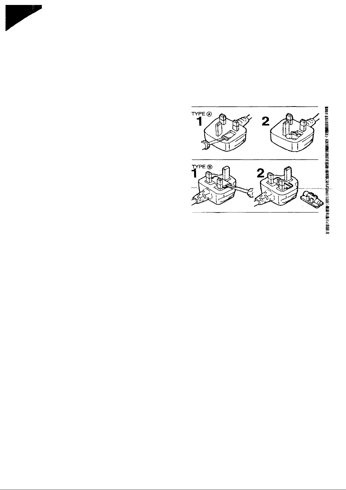
How to replace the Fuse
•There are twQ.types of the AC Mains Lead
assembly: ® and ® as shown below
1 Open the fuse compartment with a screwdriver.
2 Replace the fuse and fuse cover.
<4)
Caution for AC Mains Lead
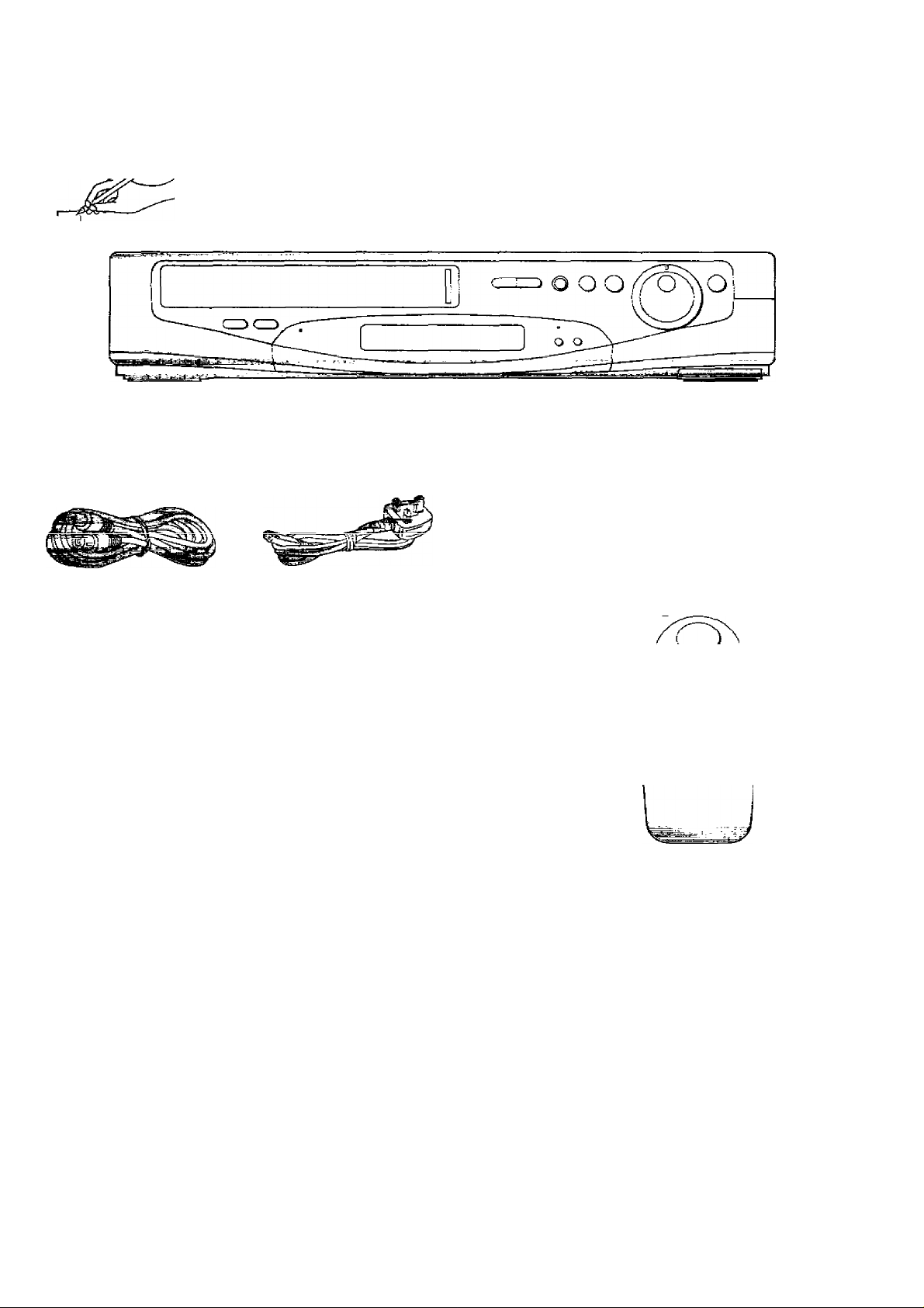
Unpacking
Check and identify the supplied accessories, and then set up this VCR after reading “Setting up”.
_
^
V
Unpacking
□
RF coaxial cable for
connecting between this
VCR and a TV (1 pc.)
VJA0710-1 orVJA0728
□
AC mains lead [1 pc.)
VJA0733
□
..............
Batteries for the
remote controller
(2 pcs.)
UM3 or R6 type
□
Remote controller
(1 pc.)
VEQ1693
O cn Q
o a
o o o
r\ r\ r\ ^
w >—I •—I
O O O Q
<ß>

<6>

Setting Up
Connections
Tuning the TV to your VCR
The VCR supplies a signal to the TV set via the RF
coaxial cable on channel 36 of the UK broadcasting
system. Your TV must be tuned into this channel in order
to view the VCR playback picture.
If the connection to the TV includes the 21 -pin scart cable,
the playback picture can be viewed by selecting AV on
your TV. The RF coaxia! cable must still be connected as
shown on page 8. but the TV need not be tuned to
channel 36.
Auto Setup
When the VCR is turned on after connecting the aerial
lead and the mains lead, Auto setup (Auto tuning and Auto
clock setting) starts.
i
5=
CD
inrra-rea Kemote controller
Controls and Connection Sockets
This gives a detailed explanation of the function of each
button, switch and connection socket.
(7)
Connections
This telis you how to connect with an aerial, TV. etc.
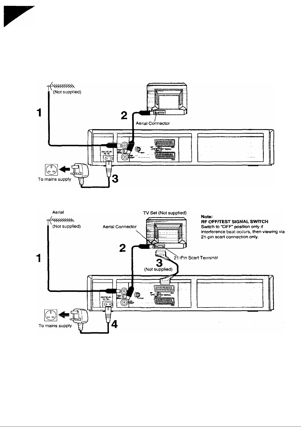
Basic Connections
The following connections are required to record and play
back the VCR through TV set;
Aerial
TV Set (Not supplied)
uonnection to a TV Set with 21-Pin Scart Terminal
<8>
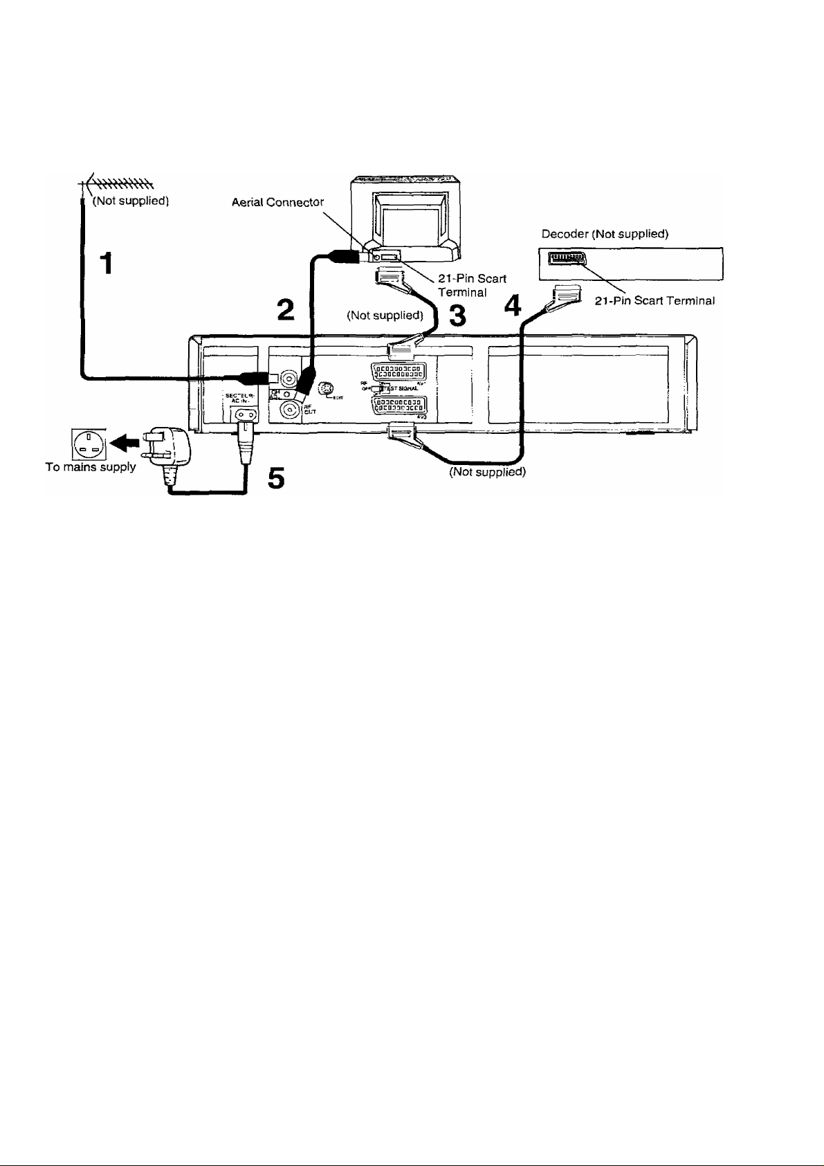
Connection to a Decoder
Connections
C3i
c
fc
CD
CO
Aerial
Notes:
•"RGB” is an abbreviation for "RED/GREEN/BLUE"’
signals. If the TV with RGB input capability is connected
to AV1 and the unit with RGB output capability is
connected to AV2, the TV can receive RGB signal from
the unit through the VCR.
• Use full-wired 21 -pin AV cables for the connection.
•Selection of RGB or norma! video output is done by the
external equipment connected to AV2 terminal.
•RF OFFiTEST SIGNAL SWITCH
Switch to “OFP position only if interference beat occurs,
tiien viewing via 21-pin scart connection only.
TV Set (Not supplied)
<9)
Tuning the TV to your VCR
Operations
CD
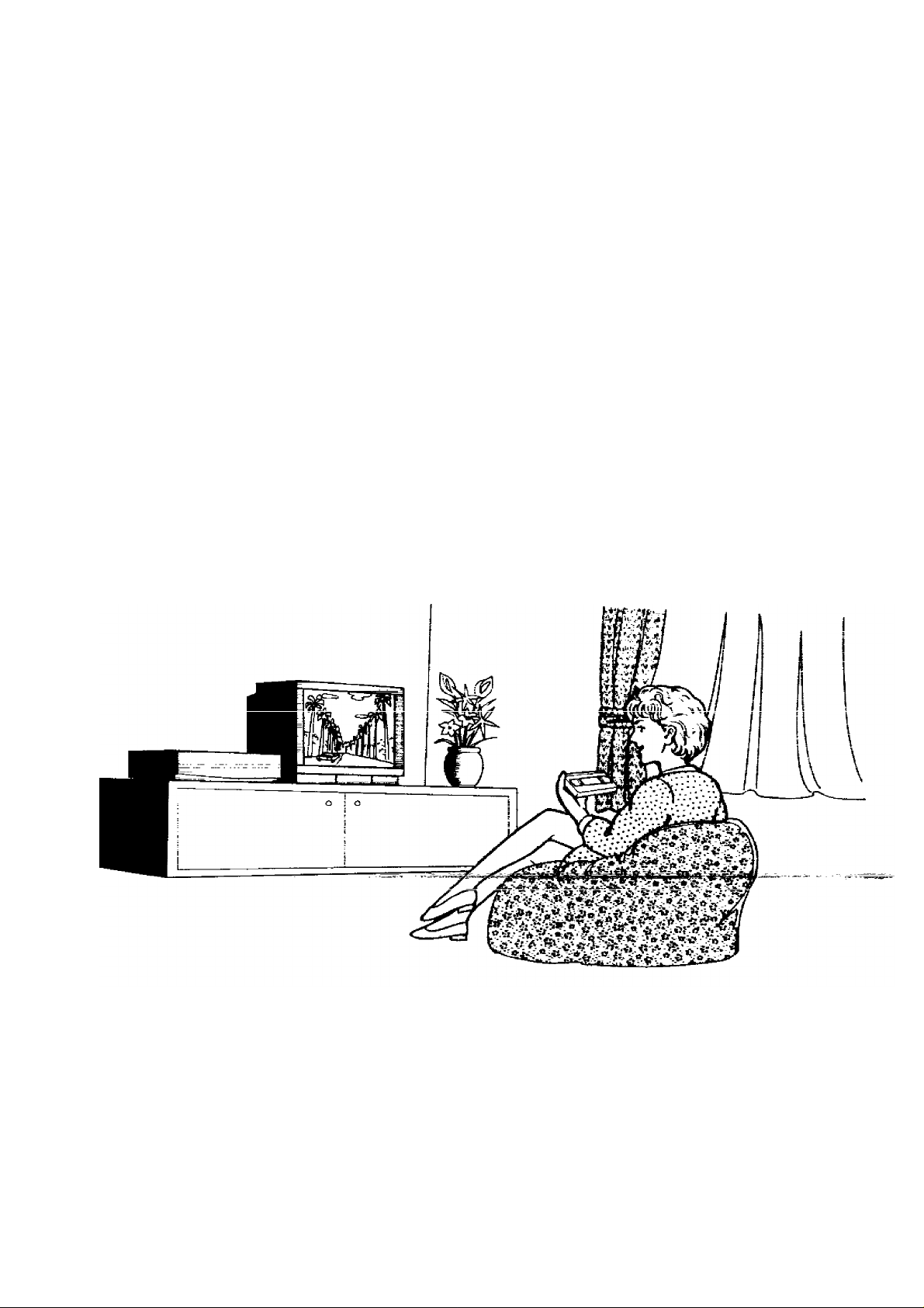
It is possible to view ttie video picture on your TV in the
same way that you watch TV broadcasts.
Jf you have connected the VCR to the TV&iroj^h the
scatfwmiinai. Then^yTO ?»'wnsea to wffewTtw - -
procedure mentioned below.
_______
Preparation
•Turn on frteTV.
• Refer to the operating instruction of the TV set and carry
out tuning/preset procedure.
Turn on the VCR.
RF ON—I
off! OtEST signal
OFF
----
i
On Screen Display
(During Auto Setup) (After Auto Setup)
RF ON—I
OffITTITEST signal
OFF
----
1
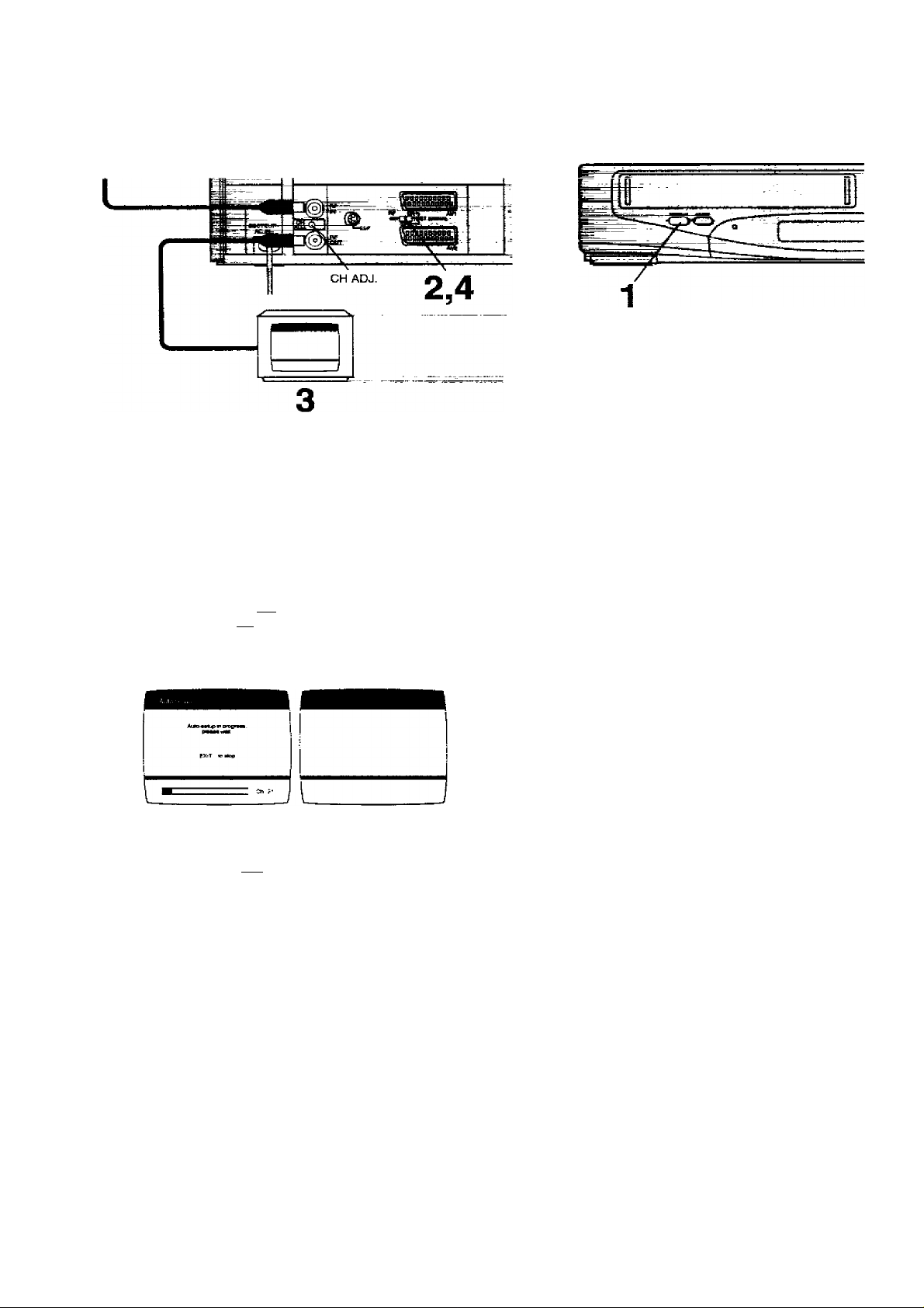
Note:
The test signal is transmitted on channel 36 of the UK
broadcasting channels. If you are encountering
interference from another broadcast on the video channel,
you may readjust to a free channel (30-42) by using the
CH ADJ. screw which is located on the rear of the VCR.
Please note that if the CH ADJ. screw is used then you
will have to retune your TV to the test signal as in item 2 to
4 above.
To generate a test pattern, set RF OFF/ TEST SIGNAL to TEST SIGNAL ON.
Set the TV to an unused position which you wish to use for your video playback.
•Tune the TV until the test pattern appears on the screen.
•On Panasonic TV the programme number 0 should be
selected to obtain best performance.
•When the VCR is turned on after connecting the aerial
lead and the mains lead. Auto setup (Auto tuning and
Auto clock setting) starts. (See next page.)
Set RF OFF/TEST SIGNAL to TEST SIGNAL OFF.
<10)
Auto Setup
Auto Setup
When the VCR is turned on after connecting the aerial
lead and the mains lead, Auto setup (Auto tuning and Auto
clock setting) starts.
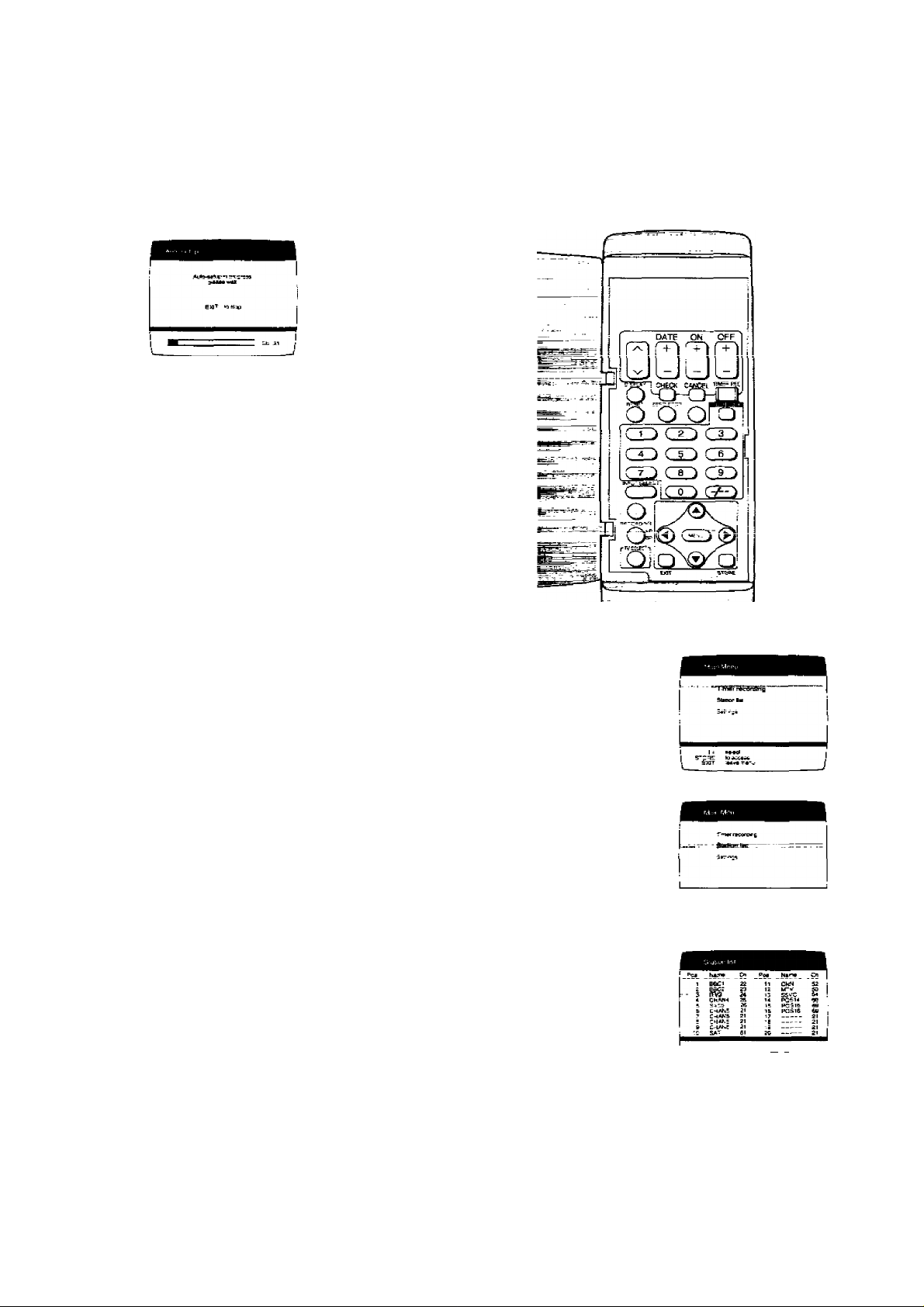
On Screen Display
•The Auto setup is searching for TV station from minimum
to maximum and memorizing the data for every
programme position.
•The Auto setup takes two or more minutes to complete
the search for TV station and the clock setting.
• !f the clock setting screen appears after auto setup has
been completed, refer to page 39 and proceed with the
setting.
Note:
If VCR is not correctly set by Auto setup, see Various
Settings on pages 34, 35 and 39.
Tuning the TV to your VCR
Auto Setup
Viewing the TV station list
Preparations
•Confirm that the TV is on and the VCR viewing channei
is selected.
•Turn on the VCR.
.S'
Cb
CO
1 Press MENU.
2 Select Station list.
0
Q
0
3 Select the desired TV station, if you want to view the
broadcast.
0
Q
0
IT I
1 STC№ tfw*>»iirtdb>aadcasa' !
<11)
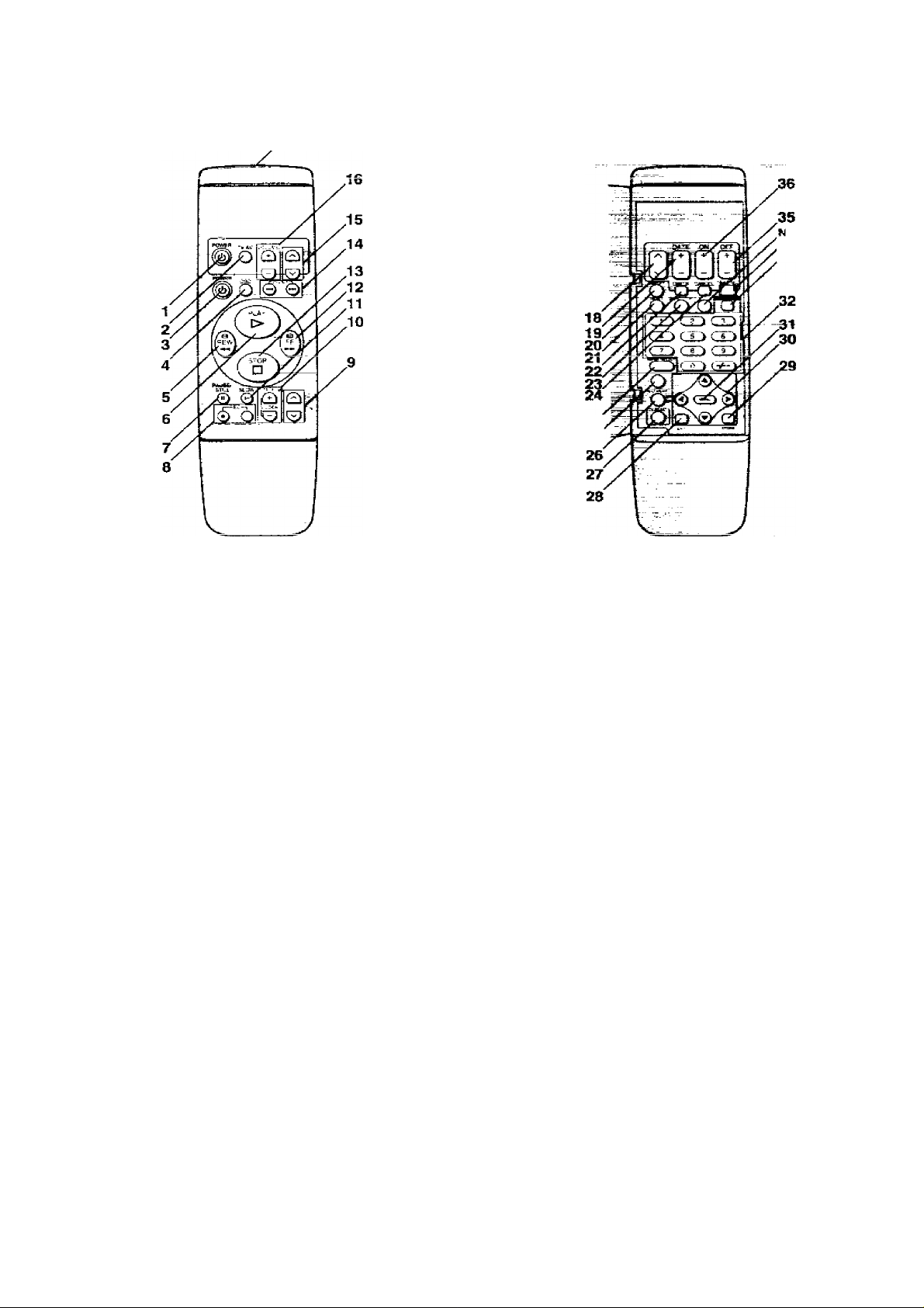
Infra-red Remote Controller
17
, )o function
(12)
1 POWER (TV)
To switch the TV from on to standby mode or vice
versa. In standby mode, the TV is stilt connected to
the mains.
•With some TV models, it may only be possible to
switch the TV to standby mode using this button.
In this case, use TV/AV or v' ^ (TV) to switch the
TV on.
2 TV/AV
To select the TV input.
3 POWER (VCR)
To switch the VCR from on to standby mode or vice
versa. In standby mode, the VCR is still connected to
the mains.
4 OSD
For the On Screen Display Function.
5 REW (REWIND)
In the stop mode: To rewind the tape.
In the playback mode: To search backward.
In the rewind mode: To obtain high speed picture,
is lit.
6 PLAY
To Start playback. ">” is lit.
7 PAUSE/STILL
During playback: Still picture.
During recording: To interrupt recording.
8 REC
To start a recording.
• Press both buttons simultaneously.
9 ^ ^ (VCR)
To select the required programme position (TV
station) of the VCR.
No function
25
10 TRACKINGA/-LOCK
To adjust the tracking and the vertical locking,
(See page 19.)
11 SLOW
For the slow motion playback function. “Dt>" is fit
12 FF (FAST FORWARD)
in the stop mode: To fast forward the tape.
In the playback mode: To search forward.
In the fast forward mode: To obtain high speed
picture,
"[>i>"isnt.
13 STOP
To stop any playback or recording,
14 INDEX
For the index search function.
15 >x<TV)
To select the required programme position (TV
station) of the TV.
16 VOLUME
To adjust the volume of the TV.
17 Infra-red Transmitter
The programming data are transmitted from here to
the VCR.
18
To programme a timer recording.
19 DATE
To programme a timer recording
20 DISPLAY
To change the indication on the VCR Display.
|-^CIock^Counter^Remaining Tape Time---------------1
Infra-red Remote Controller
C33
21 RESET
To reset the tape counter (elapsed time) to “0:00.00".
•The tape counter is automatically reset to "0:00.00"
when a video cassette is Inserted.
22 CHECK
To check timer programmes.
23 ZERO STOP
For the zero stop function.
24 CANCEL
To cancel the settings made for a timer recording.
25 INPUT SELECT
To select the A1, A2 or A3 external recording source.
26 RECORDiNG SPfLP
To select the tape speed desired for recording.
SP gives the best picture quality.
LP gives the longest recording time.
27 TV SELECT
To set the remote controller for operation of the TV.
28 EXIT
To make On Screen Display disappear on the TV
screen.
29 STORE
To make selections from On Screen Display.
30 A ▼ ◄ ►
To make selections from On Screen Display.
31 MENU
To make On Screen Display Main Menu appear on
the TV screen.
32 Programme Position Selector Buttons
•To select the programme positions (1-99).
9: CO
How to select the remote control mode
This remote controller has two remote control modes
VCR1 and VCR2.
igj Remote control mode vCRI;
Press A while holding TV SELECT.
Set to this position on both the VCR and remote
controller for norma) use with one VCR.
(§)■ Remote control mode VCR2;
Press T while holding TV SELECT.
Set to this position when using two Panasonic
VCRs.
© When the VCR mode is not known: Point the remote
controller at the VCR and proceed with step ® or .©■. If
the mode established matches the VCR mode, the
d rr*srsK#
Refer to page 38 as well.
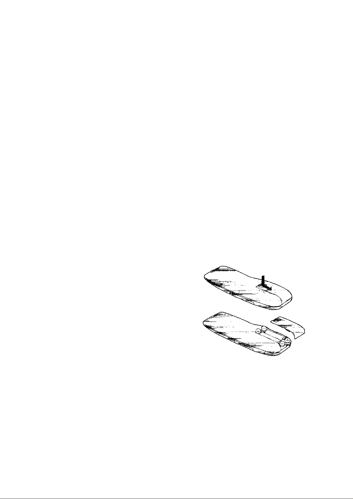
Power Source for the Remote Controller
The remote controller is powered by 2 "AA", "UM3" or "R6''
size batteries. The life of the batteries is about one year,
although this depends on the frequency of use.
Precautions for Battery Replacement
• Load the new batteries with their polarity (0 and ©)
aligned correctly.
•Do not apply heat to the batteries, or an internal
short-circuit may occur.
• If you do not intend to use the remote controller for a
long period of time, remove the batteries and store them
in a cool and dry place.
• Remove spent batteries immediately and dispose of
them,
• Do not use an old and a new battery together, and never
use an alkaline battery with a manganese battery.
Installing the Batteries
CO
19:(2D-C0-C0
•To enter a PlusCode.
33 VIDEO PLUS+
Forthe Video Plus+ programming.
34 TIMER REC
To turn the timer recording function on and off.
H is lit or not lit.
Once operating timer recording function, the normal
VCR operation is not possible unless this button is set
to off.
35 OFF
•To programme a timer recording.
•To set the manufacturer number of the TV.
36 ON
To programme a timer recording.
<13>
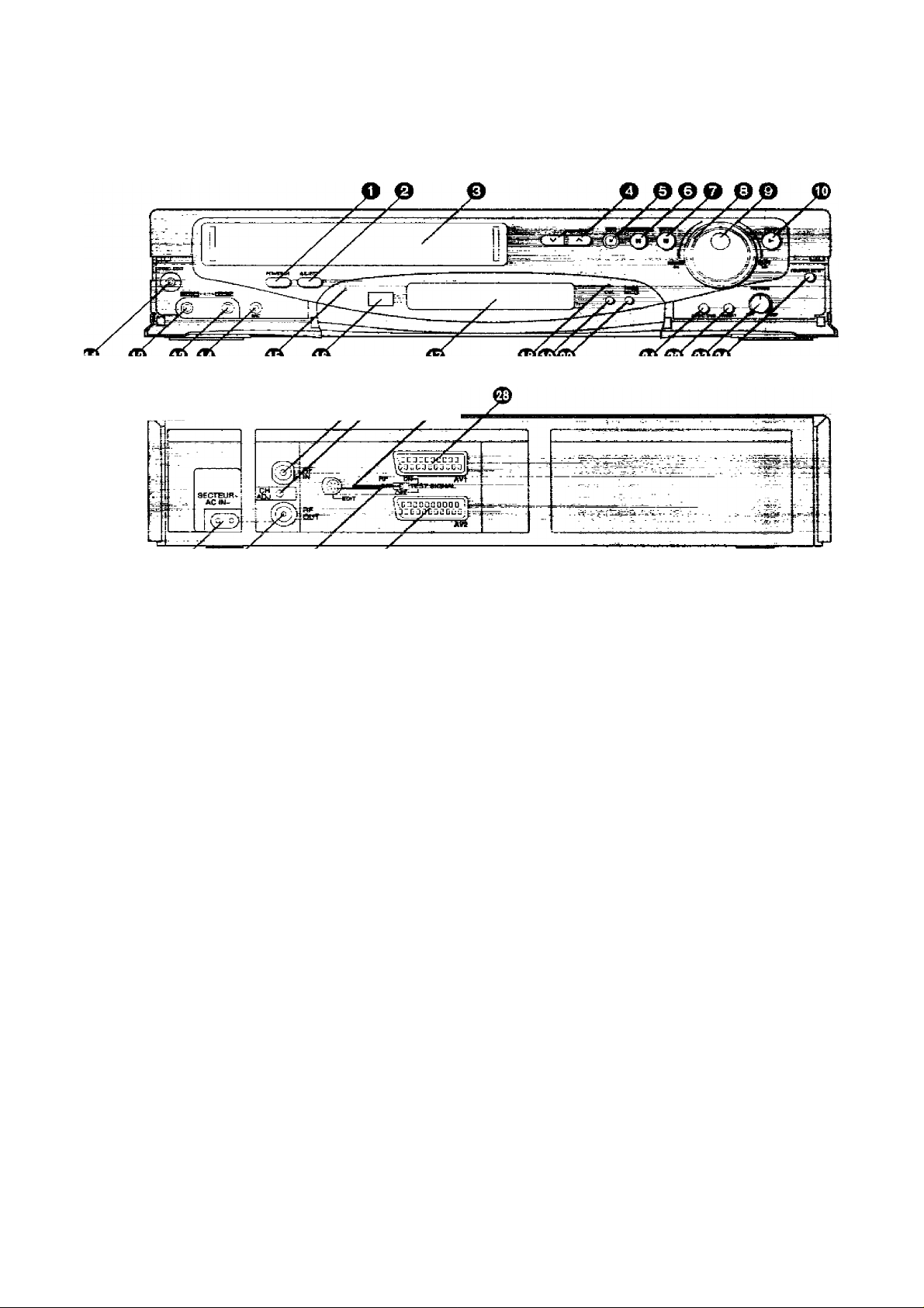
Controls and Connection Sockets
This gives a detailed explanation of the function of each button, switch and connection socket.
O POWER <!)/!
Press to switch the unit from on to standby mode or
vice versa. In standby mode, the unit is still
connected to the mains.
Q EJECT
To eject a video cassette.
Q Cassette Compartment
Insert a video cassette here.
O ^
To select the required programme position (TV
station).
0 REC
To start a recording.
© PAUSE/STILL
In the stop mode: Still picture (Jog/Shuttle mode).
During playback: Still picture (Jog/Shuttie mode).
During recording: To interrupt recording.
O STOP
To stop any playback or recording.
O Shuttle Ring
In the stop mode: To rewind or fast forward the tape.
In the playback mode:
In the still playback mode:
In the rewind or fast forward mode:
<14)
w w
To search picture backward or
forward.
To adjust playback speed
backward or forward.
To obtain high speed picture.
w
WWW
© Jog Dial
To locate any desired frame with utmost precision.
© PLAY
To start playback. is lit.
© SYNC. EDIT
To connect a movie camera or another VCR
equipped witn synchronized edWngTapaiHmy.
To connect a movie camera or another VCR
equipped with LANC socket for One-Touch-Edttfng.
0 VIDEO IK (AV3)
To connect the video cable to a movie camera or to
another VCB.
0 AUDIO IN (AV3)
To connect the audio cable to a movie camera or to
another VCR.
© MIC
To connect a microphone for recording. Once
connected, this socket has priority.
© Standby Indicator
This indicator is lit when the VCR is turned off or the
VCB is timer recording standby mode.
© Infra-red Remote Control Receiver Window
© Display
0 CVC Indicator
When the CVC function is on. this indicatof is lit.

Controls and Connection Sockets
3-
CVC (Crystal view Control)
ON: Using the CVC function, playback and
recording are performed In the stale which
achisvss optimum picturo Quality in fipht of
characteristics of a tape.
•The CVC indicator is lit.
•This control should normally be left in the
ON position.
OFF: Turn off the CVC function.
•The CVC indicator is not lit.
^ TIMER REC
To turn the timer recording function on and off.
□ is lit or not lit.
Once operating flmer recording function, the normal
rtnafta+irtn ie> i mlAoe« fkilc Ki i+trttn io
V^l«W|_rC3(«ALIWII IlS IIV/L Wl II ■■•>3 k,/M LllvM I 1^
to off.
0) AUDIO DUB
To set up the VCR for audio dubbing.
A DUB is appeared on screen display.
^ INSERT
To set up the VCR for insert editing.
INSERT is appeared on screen display.
® PICTURE
To make picture sharper (SHARP) or softer (SOFT).
0 COUNTER RESET
To reset the tape counter (elapsed time) to “0;00.00".
•The tape counter is automatically reset to “0;00.00"
when a video cassette is inserted.
0 RFIN
To connect to the external aerial.
@ CHADJ.
To adjust the RF transmitting channel 30-42.
® RFOFF/TEST SIGNAL
RF OFF; Set to this position when the VCR is
cfflnnected to the TV via the 21-pin scart
TEST SIGNAL OFF;
TEST SIGNAL ON:
cable.
Set to this position when the VCR is
connected to the TV via the RF coaxial
cable only.
Set to this position when tuning the TV into
the VCR.
The test signal is transmitted on
channel 36 initially.
© AV1
This 21-pin scart terminal carries input and output
signals for both picture and sound. TV sets equipped
wjth p 3jnfji!3r soGk0t G3.P* b6 conn6Gt6ci h0r8.
This is also called Scart
Peritel
Euro Connector
Euro AV
20 tB t6 14 12 ICI 8 6 4 a
\ <> i> "{> O i> i> O <> i? €■
\p O O O O O i> O i> O O’ I
19 IT rs 13 11 0
1 AUDIO OUTPUT
2 AUDIO INPUT 14 BLANKING
3 AUDIO OUTPUT GROUND
4 AUDIO GROUND
BLUE GROUND
5
AUDIO INPUT 17
6
BLUE
7
SWITCHING VOLTAGE
8
GREEN GROUND
9
10 No connection 19 VIDEO OUTPUT
11 GREEN 20 VIDEO INPUT
12 No eonneciion 21 GROUND
Note; RED, GREEN and BLUE are inputs only.
© AC IN
TO connect to the main power supply.
^ RFOUT
To connect to the aerial terminal on a TV set.
0) EDIT
By connecting the optional Editing Controller
(VW-EC300EA/W-EC310E) to this socket, such
editing functions as Assemble Editing. Insert Editing
and Audio Dubbing can be performed more quickly
and efficiently between two VCRs or between a VCR
eind a movie camera.
To connect the Edit cable (VW-K5E) to a movie
camera or to another VCR for One-Touch-Ediling.
0 AV2
To connect to a decoder or another VCR.
•The 21-pin list is same with AVI.
7 B
3 1
RED GROUND
13
RED
15
BLANKING
16
VIDEO OUTPUT
GROUND
18 VIDEO INPUT
GROUND
.....
CO
...
<15)
 Loading...