

Page 1
' * v ,v; ;
I:'''-# -i,;
' ,i ' .tj,. 'iff'"v*)!
Operating Instructions
Video Cassette Recorder
NV-SD1 s.*s
\/QT5534
vus
Before attempting to connect, operate or adjust this
product, please read these instructions and then
retain them for future reference.
SrfTMM
Page 2

Dear Customer
We take this opportunity to thank you for purchasing this
Panasonic Video Cassette Recorder.
We particularly advise that you carefully study these
Operating Instructions before attempting to operate the unit and
that you note the listed precautions.
Information for Your Safety
Contents
Setting Up
Connections.................................................................... 3
Tuning the TV into your VTR
Setting the Clock of the VTR
Storing TV Broadcasts into your VTR
.........................................
.........................................
..........................
4
5
6
IMPORTANT
Your attention is drawn to the fact that
recording of pre-recorded tapes or discs
or other published or broadcast material
may infringe copyright laws.
WARNING
TO REDUCE THE RISK OF FIRE OR
SHOCK HAZARD, DO NOT EXPOSE
THIS EQUIPMENTTO RAIN OR
MOISTURE.
NV-SD1A: Australian model
NV-SD1EA: New Zealand model
FOR YOUR SAFETY
■ DO NOT REMOVE OUTER COVER.
To prevent electric shock, do not remove
cover. No user serviceable parts inside. Refer
servicing to qualified service personnel.
HQ (High Quality) Picture System
Video recorders carrying the HQ symbol mark feature the
new VHS High Quality Picture System, This system
assures complete compatibility with VTRs that use the
conventional VHS system.
Description
Controls and Connection Sockets
Basic Operations
Playback............................................................................ 10
On-the-spot Recording
•Assembly Editing
...................................................
..............................................................
12
13
Advanced Operations
Timer Recording............................................................... 14
Search Function
•VHS Index Search System
...............................................................
...............................................
16
16
Helpful Hints
Before Requesting Service............................................ 17
Precautions..................................................................... 19
Specifications......................................................Back Cover
Page 3
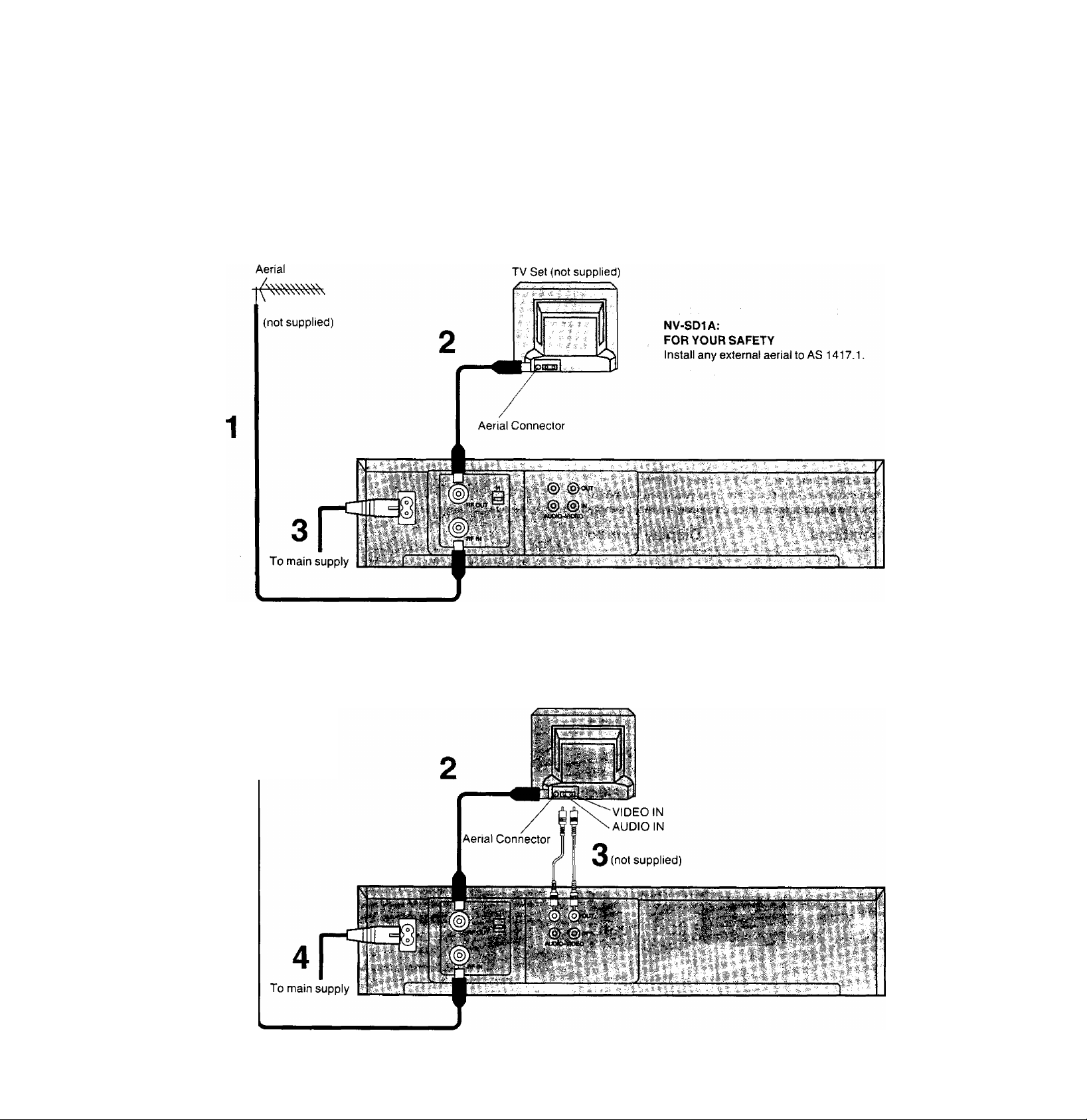
Connections
This tells you how to connect the VTR to an aerial, TV, etc.
Basic Connections
The following connections are required to record and play
back the VTR through a TV set:
Connection to a TV Set equipped with Audio/Video Input Sockets
Aerial
(not supplied)
TV Set (not supplied)
1
Page 4
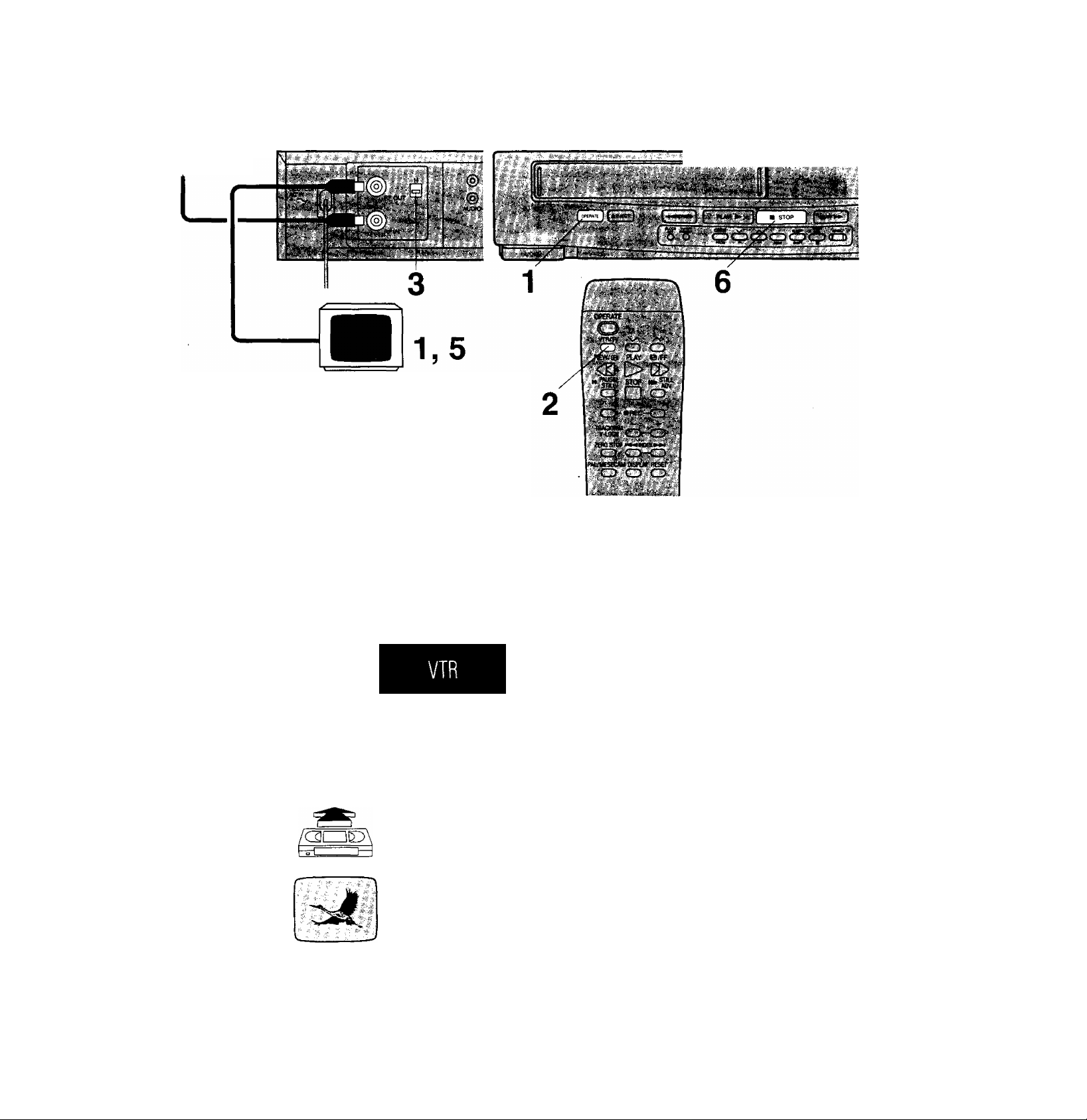
Tuning the TV into your VTR
The VTR supplies a signal to the TV set via the RF coaxial
cable.
For Australia: on channel 0 or 1
For New Zealand: on channel 2 or 3
It is possible to view the video picture on your TV in the
same way that you watch TV broadcasts.
If you have connected the VTR to the TV through the
video and audio input sockets then you do not need to
follow the procedure mentioned below. Instead, simply select AV mode on the television.
Operations
1
OPERATE
VTR/rV
o
H
Display Symbols
Turn on the TV and VTR.
Select the VTR mode.
Select the video playback channel which is
not occupied with any TV station.
NV-SD1 A; L (channel 0) or H (channel 1)
NV-SD1EA: L (channel 2) or H (channel 3)
Insert a recorded cassette tape.
•To start the playback, see page 10.
Select a programme number on the TV set
which you wish to use as the video viewing
channel. Then tune in the TV to the picture
from the cassette tape currently playing.
• NV-SD1Aonly
in some areas channel 0 may be used by local TV station.
In this case switch to channel 1.
STOP
Stop the playback.
Page 5
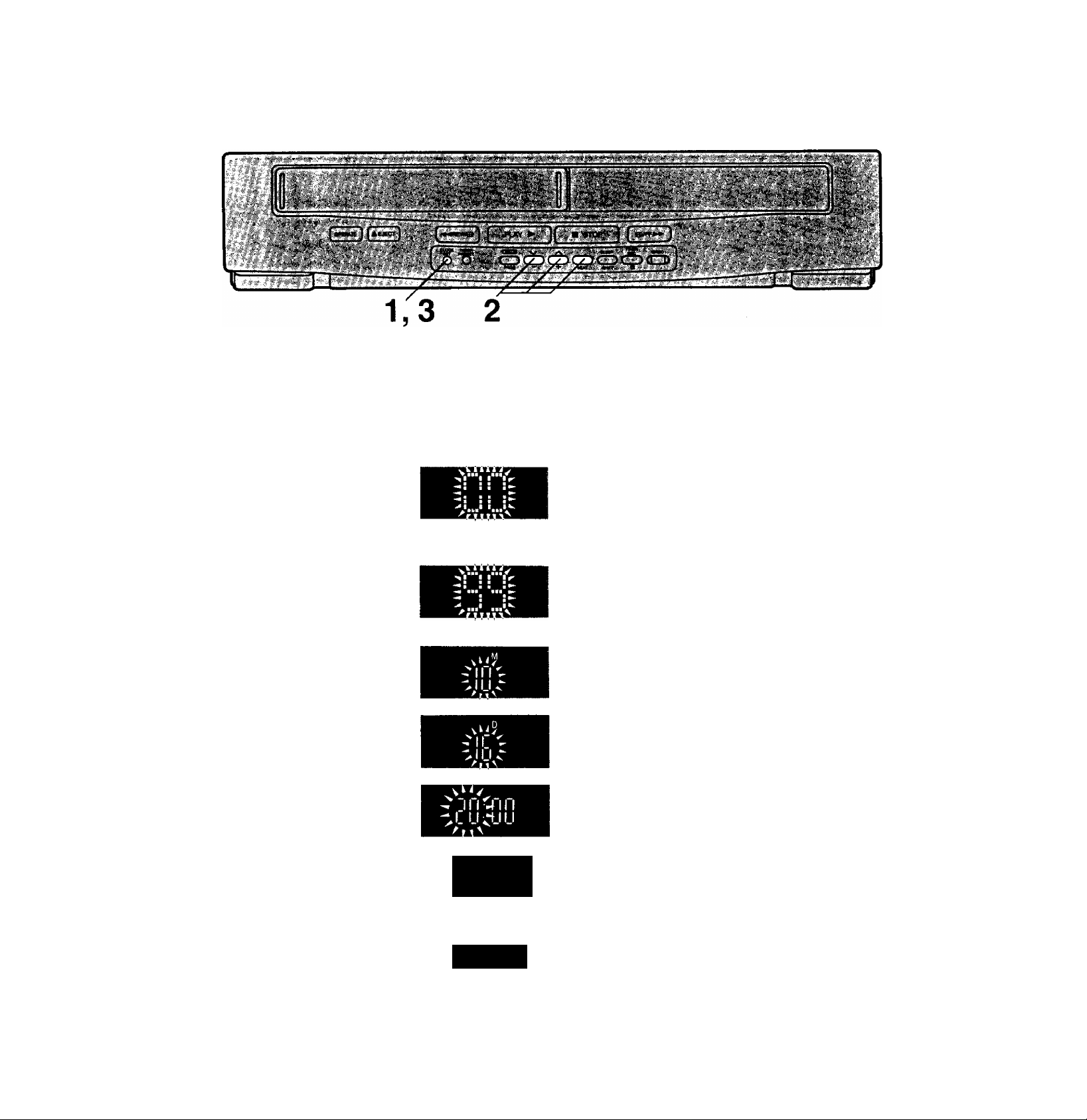
Setting the Clock of the VTR
The built-in clock is used to activate the timer for automatic
recording and must be set to the correct time.
The built-in digital clock employs the 24-hour system.
Preparation
Turn on the VTR.
Operations
1
2 Set each item by pressing + or — and NEXT.
CLOCK
SET
©
/\
Display Symbols
Note:
The clock operates for at least 5 minutes by its backup
system in the event of po\wer failure.
For Example:
Date; 16th, October, 1999
Time; 20:15
Keep CLOCK SET pressed for more than
2 seconds.
Set Year “99”.
Set Month “10”
o
- -
L IJ
CLOCK
SET
©
CIJ 1%
Time Reset Function
If the clock is less than two minutes slow or fast, it can
easily be reset to the proper time.
For example; Resetting the clock to 12:00.00.
Set Date “16".
Set Hour “20”.
Set Minute “15”.
•There is no need to press NEXT,
Press CLOCK SET.
•The clock will start.
1 Keep CLOCK SET pressed at any time between
11:58.00 and 12:01.59 for more than 2 seconds.
2 Press CLOCK SET again as soon as you hear the
12:00.00 time signal.
Page 6
storing TV Broadcasts into your VTR
Introduction
The VTR is fitted with its own tuner (just like a normal TV
set) and can be pre-set to receive up to 42 TV broadcast
stations.
Operations
Display Symbols
1
TUNER
PRESET
©
NEXT
I
I
Lh>l
Preparation
•Confirm that the TV is on and the VTR viewing channel is
selected.
•Turn on the VTR and press VTR/TV to select the VTR
mode.
•When selecting programme position do not select position
“A1”.
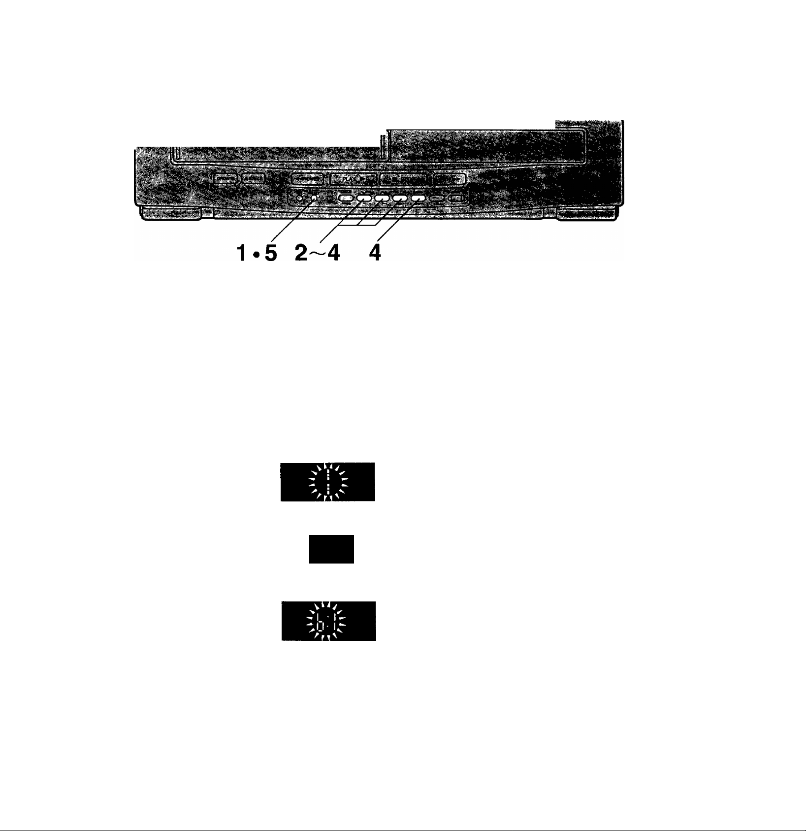
Keep TUNER PRESET pressed for more than 2 seconds.
Press + or - to select the programme position, then press NEXT.
Press + to select TV band “I”, “HI” or “U”, then press NEXT.
T"
Search for the required TV station by
pressing and holding + or
\/ /\
SLEEP
Release once the station has been found.
•Search speed changes quickly by pressing SHIFT
simultaneously with -i- or
• Press NEXT and repeat steps 2-4 for each programme
position you want to tune to a station.
Press TUNER PRESET twice.
TUNER
PRESET
©
Page 7

Fine Tuning Procedure
In poor reception areas, it may be possible to improve the
picture quality by manually adjusting the tuning,
1 Keep TUNER PRESET pressed for more than
2 seconds, until the display changes.
2 Press TUNER PRESET again (briefly).
3 Press NEXT.
4 Press + or ~ to obtain the best tuning condition.
•“A" Indicator disappears.
•To return the tuning to its former state, press SHIFT.
5 Press TUNER PRESET,
Blanking of Unoccupied Programme Positions
You can blank programme positions that are not occupied
with TV stations. They are then skipped during selection of
the programme positions and allow faster programme
selection with the v and a Buttons.
1 Keep TUNER PRESET pressed for more than
2 seconds, until the display changes.
2 Select a programme position which you do not want to
tune to a TV station, by using + or
3 Press SHIFT. is displayed.)
• Repeat steps 2 and 3 for other unoccupied programme
positions to skip during the selection of the programme
positions.
•To cancel the blanking of a programme position, select
that programme position on the VTR and then press
SHIFT.
4 Press TUNER PRESET twice.
Channel Plan
VHF UHF
'■' 'i ':
NV-SD1A 0-5 5A-11 21-69
NV-SD1EA 1-3
PRE-PROGRAMMED TV CHANNELS (NV-SD1 A)
The local TV transmission channels 2, 7,9 and 10 are
factory-preset in this VTR. That is, if you can receive
television broadcasts on VHF channels 2, 7,9 and
10, these are already tuned on the programme
positions with the matching numbers.
However, it is possible to cancel these presettings
and tune the local TV broadcast channels on any
desired programme positions.
For alternative settings and tuning of additional TV
broadcasts channels, follow the Tuning Operations.
4-11 21-69
Page 8

Controls and Connection Sockets
141516 17
21 22
■''■ii,,V- 'rj'. * i ; f *■
vV-5'. ;V'-
»1
24 25
This gives a detailed explanation of the function of each
button, svi/itch and connection socket.
1 Cassette Compartment
Insert a video cassette here.
2 OPERATE
To turn the VTR on and off.
3 EJECT
To eject a video cassette.
4 REW (REWIND)
In the stop mode: To rewind the tape.
In the playback mode: To search backward.
In the rewind mode: To obtain high speed picture.
“<]
0
” is lit.
5 PLAY
To start playback. ‘‘t>” is lit.
6 Infra-red Remote Control Receiver Window
7 STOP
To stop any playback or recording.
8 FF (FAST FORWARD)
In the stop mode: To fast forward the tape.
In the playback mode:
To search forward.
In the fast forward mode:
To obtain high speed picture.
“[»” is lit.
9 Display
10 CLOCK SET (Refer to page 5.)
To set the time.
11 TUNER PRESET {Refer to page 6.)
To initiate TV station settings for the tuner.
Page 9

12 CHECK/PROG (Refer to page 14.)
To select a timer programme number.
“P1,P2, P3...or P8”islit.
To display details of preset timer recording in the timer
standby mode.
13 V a/- +
To select the required programme position (TV
station).
To set the clock and timer recording.
14 NEXT
To proceed to the next item during setting procedures.
15 SLEEP/SHIFT
To set the time to turn off the VTR automatically. (Page 11)
To blank unoccupied programme positions. (Page 7)
16 TIMERREC(Refertopage 14.)
To turn the timer recording function on and off.
0 is lit or not lit.
The VTR can only be operated manually when the
timer recording function is off.
17 REC (Refer to page 12.)
To start a recording.
18 AC IN-
To connect to the mains power supply.
19 RFOUT
To connect to the aerial terminal on a TV set.
20 Video Playback Channel Selector
To select the video playback channel,
21 AUDIO OUT
To connect an audio cable to a TV or another video
recorder.
22 VIDEO OUT
To connect a video cable to a TV or another video
recorder,
23 RFIN
To connect to the external aerial.
24 AUDIO IN
To connect an audio cable to a video camera or
another video recorder.
25 VIDEO IN
To connect a video cable to a video camera or another
video recorder.
26 VTR/TV
To select the VTR mode or TV mode.
27 PAUSE/STILL
During playback: Still picture.
During recording: To interrupt recording.
28 ZERO STOP (Refer to page 11.)
For the ZERO STOP function.
30 DISPLAY
To change the indication on the VTR Display.
Clock-i->Counter
31 RESET
To reset the tape counter (elapsed time) to “0:00.00”.
•The tape counter is automatically reset to “0:00.00”
when a video cassette is inserted.
32 INDEX (Refer to page 16.)
For the index search function.
33 TRACKING/V-LOCK
For manual tracking adjustment;
The + and - buttons are used to adjust the tracking
when, for example, noise bars on the picture are better
removed manually than by the automatic digital
tracking control. After making a manual adjustment,
press both buttons together to return to automatic
digital tracking control.
For vertical locking adjustment;
Use the + and - buttons to minimize any vertical jitter
during still-picture playback.
34 STILL ADV
To advance a stilt picture during still playback.
35 Programme Position Selector Buttons
To select the programme positions.
36 Infra-red Transmitter
Power source for the remote controller
The remote controller is powered by 2 “UM3”, “AA” or “R6’
size batteries. The life of the batteries is about one year,
although this depends on the frequency of use.
Precautions for battery replacement
•Load new batteries with polarity {-i- and -) aligned
correctly.
•If you do not intend to use the remote for a long time,
remove the batteries and store them in a cool and dry
place.
•Do not use an old and a new battery together, and never
use an alkaline battery with a manganese battery.
Loading the batteries
29 PAL/MESECAM
This function has been disabled on Australian and New
Zealand models. It is available only on models not
intended for use in Australia and New Zealand.
Consequently, absence of function or effect of this
button is NOT a malfunction or defect.
Page 10

Playback
Operations Display Symbols
Insert a recorded cassette
tape.
m
JCWytOiSniW'ffiSET I
- ■ ■.'■ " .put rr.'riv T "■ f
■ ■'■' -;' i i' “ V <■ g
•^ .■ 1- ;!{■.■■ . '+H ■-
■ ' ■■ ■
O PLAY
REW/O
<a
PAUSE/
Start viewing the picture.
Search forward by tapping
FF.
•To change back to normal playback,
press PLAY.
Search backward by tapping
REW.
•To change back to normal playback,
press PLAY.
View a still picture.
•To advance one frame of the still
picture, press STfLL AOV,
•To continue the normal playback,
press PLAY or PAUSE/STILL
again.
10
6
Stop viewing the picture.
STOP
□
Page 11

Other Playback Functions
To obtain high speed picture during fast forward or rewind
Keep FF pressed during fast forward.
Keep REW pressed during rewind.
REW/tB) O/FF
<0 a>
Note:
Cue or review playback will be automatically stopped after
10 minutes, and still playback after 5 minutes, to avoid
damage to the VTR heads or the tape.
To return to a specified scene
1 Press RESET to set the counter to 0:00.00, while the
tape Is at the scene or position you wish to return to after
playback,
RESET
O
2 After playback, press STOP to stop the tape.
3 The tape will be rewound or fast forwarded to 0:00.00 by
now pressing ZERO STOP.
ZERO STOP
O
Automatic VTR off-time setting
Press SLEEP for the desired time.
SHIFT
• Each press gives a 30 minutes time span up to 9 hours.
•To cancel the setting time, press SLEEP repeatedly until
0:00 is set.
Other Automatic Functions
Automatic playback
When a cassette without an erasure prevention tab is
inserted, the VTR starts playback automatically.
VTR-off playback
When the VTR is off, an inserted cassette can be played
back by pressing PLAY; the VTR will turn on automatically.
Automatic rewinding
When the tape reaches its end during recording (except for
timer recording) or playback, it will automatically be
rewound to the beginning.
Automatic switching off and ejection
When the VTR is switched off, an inserted cassette can be
ejected simply by pressing EJECT. The VTR will eject the
cassette and automatically turn itself off again.
11
Page 12

On-the-spot Recording
To interrupt recording
Press PAUSE/STILL during recording.
Press again to continue recording.
PAUSE/
12
To record one TV programme while viewing another programme
1 Refer to the on-the-spot recording operations steps 1 to
3.
2 Press VTR/TV to select the TV mode.
3 Select the TV programme on your TV set you wish to
view at the present time.
Notes:
•When a video cassette with a broken off tab is inserted,
the “B3’’ indication will flash to indicate that recording is
not possible.
• The recording pause mode will be automatically released
after 5 minutes.
Page 13

Assembly Editing
This enables you to record a new segment immediately
after a previously recorded segment.
This function can be used to make up an edited tape from
other recordings or video sources,
A new scene can be added to the end of a previous one.
AUDIO/VIDEOiN
Preparation
•Connect a movie camera or another VTR to this VTR as
shown.
• Insert a recorded cassette tape with an intact erasure
prevention tab.
•Select the video source required by pressing v /v to set
"Al”on the display.
□□ HEC
w
Operations
H Search for the end of the previous
recording.
PLAY
[>
2 Press PAUSE/STILL at the end point.
„ PAUSE/
" STILL
O
Set for the new recording by pressing
3
REC.
( • REC
Start the new recording by pressing
PAUSE/STILL again.
„ PAUSE/
" STILL
O
Page 14

Timer Recording
Up to 8 programmes can be recorded up to one month in
advance by setting the timer.
Preparation
•Insert a cassette tape with an intact erasure prevention
tab.
Operations Display Symbols
1
(check!
PROG NEXT
2 Set each item by pressing + or - and NEXT.
^ /\
CDO
+
For Example:
Timer Programme number; 1
Programme position (channel); 2
Date; 27th, October
Starting time; 20;02
Ending time; 21:30
(present date; 16th October)
Select Timer Programme number “1 ”, and
then press NEXT.
P1
------------------
P1 : When something has already been
Set Programme position (channel) “2”.
Set Date "27”.
: When nothing is programmed
programmed
14
(
------
NEXT
TIMER
REC
Set Starting time (hour) "20”.
Set Starting time (minute) "02’
^
Set Ending time (hour) “21 ”.
Set Ending time (minute) “30’
•There is no need to press NEXT.
* To activate timer recording, press TIMER
REC.
a
Page 15

Timer Recording from External Signal Source
If Timer Recording is performed by a unit connected to the
Audio/Video input sockets, select the A1 indicator for the
programme position.
Setting other Programmes in Succession
Repeat steps 1 and 2.
Checking a Timer Programme in the timer standby mode
Select the timer programme number to be checked by
pressing CHECK/PROG.
Cancelling a Timer Programme
1 Release from the standby mode by pressing TIMER
REC
2 Select the timer programme number to be canceled by
pressing CHECK/PROG.
3 Press + and - simultaneously for more than 3 seconds.
15
Page 16

Search Function
VHS Index Search System
This system makes it very easy to find the beginning of
each of several recording, because a special index signal is
automatically recorded at the start of each recorded
segment on the tape. Up to 20 index signals can be
searched for in both directions.
Preparation
Insert a recorded cassette tape with recorded index signals.
For example:
Searching for the 2nd recorded segment in the forward
direction.
i
Current
tape position
Operations
Press INDEX twice.
IIWDEXI
•After finding the specific recorded segment, playback
starts automatically.
•For the reverse direction, press INDEX .
I (Start of) second segment forward
(Start of) first segment forward
Display Symbols
Recording Index Signals
Index signals are recorded in following cases.
•When a recording is started by pressing REC.
•When REC is pressed during recording.
• When timer recording is activated.
Note:
The search function can only work correctly, if the index
signals are spaced at least 3 minutes apart.
16
Page 17

Before Requesting Service
Before requesting service, check the following points once again.
VTR will not operate correctly
SYMPTOM CAUSE REMEDY
VTR display is not
illuminated.
VTR display is
illuminated but VTR
will not operate when
OPERATE is
pressed.
VTR will operate for
a few seconds then
power off.
Mains lead is not connected.
VTR is in timer mode.
Safety devices are operating. Disconnect mains lead and wait for 1 minute.
Tape is jammed in VTR. If tape is jammed in VTR, do not attempt to remove,
Reconnect mains lead to VTR.
Press TIMER REC to operate VTR manually.
Reconnect mains supply and check functions.
as this may cause damage. Consult your dealer for
advice.
Playback will not operate correctly
SYMPTOM
Picture noisy or not
in colour.
Horizontal bars or
lines run down the
screen.
Tracking is not correct.
TV set is not tuned to VTR, Check TV tuning. See page 4.
Tape is recorded incorrectly.
'cau^:-[!7':
Although auto-tracking should ensure a good picture,
it may be necessary to manually adjust tracking on
some tapes not recorded on this VTR. See page 9.
Check that aerial is connected to VTR. See page 3.
REMEDY
CHECKED
CHECKED
VTR rewinds
automatically during
playback.
Condensation may have
formed.
Tape defective due to surface
damage or wear.
Tape end detector works
during playback due to
damaged tape.
Check that each programme position is' tuned to the
correct station. A snowy picture on one or more
programmes may indicate that VTR is tuned to weak
station or wrong transmitter. Re-tune if necessary.
See page 6.
Do not operate VTR for 1 hour.
Confirm with another tape if noise free and replace
the defective tape.
Replace the defective tape.
17
Page 18

Recording will not operate correctly
;.SYMPTOM^''
“EBI” indication
flashes whenever
recording is
attempted.
Picture is recorded
with noise or blank
screen.
Timer recording
cannot be
performed.
CAUSE
Erasure prevention tab on
cassette is broken off.
Aerial or aerial lead is
defective.
VTR is not correctly tuned.
A1 is selected.
Clock or calendar is
incorrectly set.
Clock is flashing 0:00.
Recording start or stop time
settings are incorrect.
VTR is not set for timer
recording.
REMEDY
Use a tape with intact erasure prevention tab, or
cover the tab hole with adhesive tape, if the original
recording is no longer required.
Check the aerial connection to the VTR. See page 3.
Check your normal TV picture. If there is no picture,
check your aerial.
Re-tune the VTR. See page 6,
Select the required TV programme.
Check the clock and calendar. Set to the present
time. (Note this is a 24 hour clock.) See page 5.
Set the clock to the present time.
Set the recording start and stop times correctly. Try a
short timer recording a few minutes ahead of the
present time to confirm correct operation.
See page 14.
Press TIMER REC after programming for timer
recording.
CHECKED
AV external
recordings cannot be
made.
SYMPTOM
Remote controller
does not operate
correctly.
A1 is not selected.
External AV connections are
incorrect.
Remote controller will not work correctly
CAUSE
Remote controller transmitter
beam is not reaching VTR.
Distance is too far.
Batteries are exhausted.
Batteries are incorrectly fitted
with (+/-) reversed.
Select A1 (by pressing the A or V buttons).
Check that connections from the external video and
audio source are correct. See page 13.
REMEDY
Ensure that remote controller is being pointed at the
VTR and that the transmitter beam is not obstructed.
Use remote controller within 7 m of the VTR. If this
range is not possible, replace the batteries.
Replace batteries by the AA, UM3 or R6 type
available from your dealer. Note precautions for
replacement on page 9.
Fit batteries correctly as shown on page 9.
CHECKED
18
Page 19

Precautions
Please read these cautions before you operate this VTR.
Avoid Sudden Changes in Temperature
If the VTR is suddenly moved from a cold place to a warm
place, moisture may form on the tape and inside the VTR.
In this case, the Dew Indicator " d ” will flash on and off and
the VTR will not operate.
Humidity and Dust
Avoid places where there is high humidity or much dust,
which may cause damage to internal parts.
Do Not Obstruct the Ventilation Holes
The ventilation holes prevent abnormal increase in
temperature. Do not block or cover these holes. Especially
avoid covering the holes with soft materials such as cloth or
paper.
Keep away from High Temperature
Keep the VTR away from extreme direct heat such as
direct sunlight, heating radiators, or closed automobiles.
Keep Magnets away
Never bring a magnet or magnetized object near the VTR
because it will adversely affect the performance of the VTR.
No Fingers or Other Objects Inside
Touching internal parts of this VTR is dangerous, and may
cause serious damage to the VTR. Do not attempt to
disassemble the VTR. There are no user serviceable parts
inside.
Keep Water away
Keep the VTR away from flower vases, tubs, sinks, etc.
CAUTION: If liquids are spilled into the VTR, serious
damage could occur. If you spill any liquid into the VTR,
consult qualified service personnel.
Video Head Clogging
The video heads place picture signals on the tape during
recording and read picture signals from the tape during
playback and they are, therefore, of critical importance for
the picture quality. If the VTR is used over extremely long
periods of time, these heads may still become dirty and
clogged. In such a case, the signals can no longer be
recorded correctly, and the playback picture will be
distorted accordingly. This is the case, for example, during
the playback of a tape, the sound is reproduced normally,
but no picture is seen, or the picture is greatly distorted.
When such a symptom case occurs have the recorder
checked by qualified service personnel.
If Dew Condensation Forms in the VTR
Condensation may form in the VTR if:
•The VTR is in a room when the heater has just been
turned on.
•The VTR is in a room with steam or high humidity.
•The VTR is brought from cold surroundings into a
well-heated room.
•The VTR is suddenly brought from cool surroundings,
such as an air-conditioned room or car, to a place which is
hot and humid.
When dew forms in the VTR:
The Dew Indicator “d" on the Multi-Function Display will
flash on and off and all the function buttons are made
non-operational to protect the tape and the video heads.
When the Dew Indicator flashes, wait until this indicator
disappears.
•If dew condensation forms inside the VTR while the
OPERATE Switch is off, it will turn on automatically and
the Dew Indicator will flash on and off. As soon as the dew
condensation has been dissolved, the VTR will turn itself
off again.
Lightning
To avoid damage by lightning, disconnect the aerial plug
from the VTR.
Cleaning the VTR
Wipe the VTR with a clean, dry cloth. Never use cleaning
fluid, or other chemicals. And do not use compressed air to
remove dust.
Stacking
Place the VTR in a horizontal position, and do not place
anything heavy on it.
19
Page 20

Specifications
NV-SD1A, EA
Information for Your Safety
Power Source:
Power Consumption:
Video Recording System;
Video Heads:
Tape Speed:
Tape Format:
Record/Playback Time:
VIDEO
Television System:
Modulation System:
Input Level:
Output Level:
AUDIO
Input Level:
Output Level:
Audio Track:
Video Horizontal Resolution;
Signat-to-Noise Ratio:
Audio Frequency Response:
Operating Temperature:
Operating Humidity:
Weight:
Dimensions:
Standard Accessories:
NV-SD1A; 240 V AC 50-60 Hz
NV-SD1EA; 230 VAC 50-60 Hz
Approx. 21 watts
2 rotary heads, helical scanning system
2 heads
23.39 mm/sec.
VHS tape
240 min. with NV-E240
CCtR; 625 lines, 50 fields, PAL colour signal
Luminance; FM azimuth recording
Colour signal; converted subcarrier phase shift recording
VIDEO IN (PHONO): 1.0 Vp-p,
VIDEO OUT (PHONO): 1.0 Vp-p,
RF Modulated: NV-SDIA: VHF channel 0 or 1,
NV-SD1EA: VHF channel 2 or 3,
AUDIO IN (PHONO);
AUDIO OUT (PHONO);
1 track (Normal-mono only)
Colour; more than 240 fines
Video: more than 43 dB
Audio: more than 43 dB
80 Hz-10 kHz
5"C-40°C
35%-80%
4.3 kg
430 (W)x91 (H)x273 (D) mm
1 pc. DIN-DIN Coaxial Cable
1 pc. Remote Controller
2 pcs. ‘‘R6" “AA” size batteries
1 pc. AC Mains Lead
more than -10 dBV,
-6dBV,
75 ohm
75 ohm
75 ohm
75 ohm
more than 50 kohm
1 kohm
Weight and dimensions shown are approximate.
Specifications are subject to change without notice.
Printed in Japan
VQT5534
F0194T1014-11000I
Matsushita Electric Industrial Co., Ltd.
Central P.O. Box 288, Osaka 530-91. Japan
 Loading...