

Page 1

Video Cassette Recorder
NV-L25 Series
Operating Instructions
VQT2977
VMS
Before attempting to connect, operate or
adjust this product, please read these
instructions completely.
Page 2

Page
3 CAUTIONS
4 CONTROLS AND COMPONENTS
6 INFRA-RED REMOTE CONTROLLER
8 INSTALLATION
9 TUNING THE TV SET TO THE VIDEO PLAYBACK
CHANNEL
10 SETTING THE TUNER IN THE VTR
12 SETTING THE CLOCK TO THE PRESENT TIME
14 THE VIDEO CASSETTE
14 AUTO OPERATION
15 PLAYBACK
20 RECORDING FROM A TV BROADCAST SIGNAL
21 SUPER OTR FUNCTION (ONE-TOUCH TIMER
RECORDING)
23 TIMER RECORDING
29 VHS INDEX SEARCH SYSTEM
30 INTRO SCAN FUNCTION
31 TIME SEARCH
IMPORTANT
Your attention is drawn to the fact that
recording of pre-recorded tapes or discs
or other published or broadcast material
may infringe copyright laws.
WARNING
TO PREVENT FIRE OR SHOCK HAZARD,
DO NOT EXPOSE THIS EQUIPMENT TO
RAIN OR MOISTURE.
NV-L25A: Australian model NV-L25EA: New Zealand model
FOR YOUR SAFETY
■ DO NOT REMOVE OUTER COVER.
To prevent electric shock, do not remove
cover. No user serviceable parts inside. Refer
servicing to qualified service personnel.
is the safety information.
; HG (Htg^ Qual Picture Systerrr
Video recorders carrying the HQ symbol mark feature the
new VHS High Quality Picture System. This system as
sures complete compatibility with VTRs that use the con
ventional VHS system.
32 CAMERA RECORDING
33 DUBBING (COPYING)
35 INSERT EDITING
36 AUDIO DUBBING
37 BEFORE REQUESTING SERVICE
39 SPECIFICATIONS
HQ
Page 3

O
Please read these cautions before you operate this VTR.
Cassette Coiii pertinent Door
When first unpacking the unit, you may notice that the
cassette compartment door is partially open. This condition
is due to the operation of a safety device designed to
protect the unit from vibration during shipment; it is not a
malfunction. When the AC mains lead is connected to a
mams outlet, the door will return to its original position.
IBISllSHffi
If the VTR is suddenly moved from a cold place to a warm
place, moisture may form on the tape and inside the VTR.
In this case, the Dew Indicator “r " will flash on and off and
the VTR will not operate.
Humiditvt and Ekist
Avoid places where there is high humidity or much dust,
which may cause damage to internal parts.
m
The ventilation holes prevent abnormal increase in temper
ature. Do not block or cover these holes. Especially avoid
covering the holes with soft materials such as cloth or
paper.
Keep the VTR away from extreme direct heat such as direct
sunlight, heating radiators, or closed automobiles.
Never bring a magnet or magnetized object near the VTR
because it will adversely affect the performance of the VTR,
Ha or 0№her Objects liteide
Touching internal parts of this VTR is dangerous, and may
cause serious damage to the VTR. Do not attempt to dis
assemble the VTR. There are no user serviceable parts
inside.
Keep Water away
i
Place the VTR in a horizontal position, and do not place
anything heavy on it.
To avoid damage by lightning, disconnect the aerial plug
from the VTR.
The video heads are the means by which the recorder
places picture signals on the tape during recording, and
reads picture signals from the tape during playback. If these
heads become dirty and clogged from use, the signals can
no longer be recorded correctly, and the playback picture
will be distorted accordingly. This is the case, for example,
during the playback of a tape, the sound is reproduced
normally, but no picture is seen, or the picture is greatly
distorted. When such a symptom case occurs have the
recorder checked by qualified service personnel.
im mmm
Condensation may form in the VTR if:
• The VTR is in a room where the heater has just been
turned on.
• The VTR is in a room with steam or high humidity,
• The VTR IS brought from cold surroundings into a wellheated room.
• The VTR is suddenly brought from cool surroundings,
such as an air-conditioned room or car. to a place which is
hot and humid.
When dew forms in the VTR: (Refer to page 5.)
The Dew Indicator "r " on the Multi-Function Display will
flash on and off and all the function buttons are made non-
operaiional to protect the tape and the video heads.
When the Dew Indicator flashes, wait until this indicator
disappears.
• If dew condensation forms inside the VTR while the VTR
On/Off Switch is off, it will turn on automatically and the
Dew Indicator will flash on and off. As soon as the dew
condensation has been dissolved, the VTR will turn itself
off again.
maam
Keep the VTR away from flower vases, tubs, sinks, etc.
CAUTION; if liquids are spilled into the VTR, serious
damage could occur. If you spill any liquid into the VTR,
consult qualified service personnel.
Wipe the VTR with a clean, dry cloth. Never use cleaning
fluid, or other chemicals. And do not use compressed air to
remove dust.
Page 4

FRONT
Q Q0O0QOQ Q<D 0 0 00000 0
cm
rzii ~i CD
CD cp up q q|c3 □ g aicp eg cp
CbCl CZXZ3
izn
i
0 0 0 0 0
No. Description
0 VTR On/Off Switch with Indicator 9
0 Rewind -<^/Review @ Button 15 0 Clock/Counter Selector
000
Page
0 000 0
No. Description
0 Multi-Function Display
©
m
a
Page
5
19
0 Play/x2 Button
0 Fast Forward ►►/Cue Q Button 15
0 Stop Button (■) 15
0 Pause/Still Button (II) 15 0 Digital Tracking Selector
0 Record Button (•)
0 Cassette Compartment 14
0 Audio Dubbing Button
0 Insert Editing Button 35
0 Channel Selection Up and Down Buttons
0 OTR On Buttons 21 0 Band/AFC Button
0 OTR Off Buttons
0 Eject Button (A)
0 Audio Dubbing Indicator
0 Insert Editing Indicator
15
20
36
10 0 Timer Controls
21 0 Clear Button
14
36
35
0 Microphone Input Socket
0 Picture Sharpness Control
0 Noise Filter/Edit Selector
0 Tape Speed Selector
0 VTR/TV Selector 9
0 Clock Button
0 Preset/Fine/Normal Button
0 Timer Record Button
0 Infra-red Remote Control Receiver
0 Reset Button
36
15
19
18
20
12
10
10
10
11
24
6
19
0 Digital Tracking Indicator
18
Page 5

Multi-Function Display
12345678
SUM01
rUWETHFRSA
SP LP mniFF ^
®-C0UNT_
When dew forms: ^
Dew Indicator
'I''
No. Description
Cassette-in Indicator
Tape Running Display
@ Timer Recording Indicator
@ Double Speed Indicator
@ Recording Indicator
@ OTR Indicator 21
(7) Date Display
Page
14
15
24
15
20
12
No. Description
Q Audio Input Socket
0 Audio Output Socket
0 RF Output Socket
0 Vertical Lock Controls 19
0 Synchro Edit Socket 34
0 AC Mains Lead Socket
0 Video Input Socket
0 Video Output Socket
0 RF input Socket
0 Video Playback Channel Selector
0 Test Signal Switch
Page
32
8
8
8
32
8
8
9
9
Clock/Counter Indicator
@ Search Indicator 15
@ Repeat Indicator
Memory Indicator
(J2) Counter Mode indicator
@ Tape Speed Indicator
@ Timer Programme Number
(1^ Channel Display 10
(Ì6) Position Indicator
(Ì7) VTR Indicator
12
17
19
18
20
23
10
9
:5)
Page 6

Use ^ Digital Scanner
Slide the Mode Selector Cover downward.
(T) Bar Code Reader Display
-jsu MO TU WE TH FR SA
—Wl\88t
73N
---------
DO OQ
uu UO
T5FF
D 0 • OO
uo qo
^ VTR On/Off Button
^ Clock/Counter Selector
0 Reset/Index Button
(3 Record Buttons (•)
0 Pause/Still Button (I |)
0 Stop Button (■)
0 Rewind ◄^^Review @ Button
0
Slow Buttons
0 Mode Selector Cover
0 Time Search Button
(D Monitor Button
0
Programme Position (Channel) Selector Buttons
0 Fast Forward ►►/Cue © Button
0 Play/x2Button{►)
0 Still Advance Button (ili^)
0 Reverse Play Button
0
Memory/Repeat/Search Button
0 VTR/TV Selector
0 Date Display
0 Channel Display
0
Start Time Display
0 End Time Display
0
Check Indicator
@ Digital Scanner On/Off Button
Bar Code Reading Section
(i) Transmit Button
Note:
To be able to use the unit as Remote Controller, press the
Digital Scanner On/Off Button (the indications in the LCD
Display will disappear,
;6>
Page 7

How to Operate the Remote Controller
(Digital Scanner)
Press the Digital Scanner On/Off Button to “ON”.
• If no operation is performed for more than 25 seconds (4
minutes during setting of the clock time), the scanner will
automatically switch over to the power-saving standby
condition and the lamp will go off. (In this case, it bar
codes have already been read but not yet transmitted to
the VTR, the data will be cancelled.)
• When the lamp Is not lit, press the button to “ON” again.
(A) Place the Remote Controller on the Small Box.
(B) Trace the bar code quickly in the direction of the arrow.
Power Source for the Remote Controller
■ The Remote Controller is powered by 4 lEC “R03” size
batteries. The life of the batteries is about one year,
however, it depends on the frequency of use. Inspect
and if necessary, replace the batteries once a year.
CAUTION FOR BATTERY REPLACEMENT
• Load the new batteries with their polarities (+ and -}
aligned correctly.
• Do not apply heat to batteries, or internal short-circuit may
occur.
• If you do not intend to use the Remote Controller for a
long period of time, remove the batteries and store them
in a cool and dry place.
• Remove spent batteries immediately and dispose of them.
• Do not use an oid and a new batteries together. (Also
never use an alkaline battery with a manganese battery.)
Load the batteries as follows:
Q Push back the battery compartment locking lever.
@ Lift off the battery compartment lid.
• Treat the Programming Sheet with care. If the sheet
gets dirty or scratched, the bar code reading may
become impossible.
• Protect the Remote Controller from strong shocks
and vibration. Keep it away from water and places
with high temperature and humidity.
• If the bar code is traced slowly, it cannot be read
correctly.
• When there is no “Beep” sound, the reading of the
bar code is incomplete. Always check your Display
Window to confirm the function scanned has been
accepted,
• When using the Programming Sheet, put it on flat
surface: Reading the bar codes while holding it in
your hand or bending it, may result in incorrect op
eration,
• Do not deviate from the bar code, nor stop tracing
halfway.
€> Insert the batteries with their polarities aligned as indi
cated inside the battery compartment.
Q Replace the lid.
Note;
•The infra-red beam should be transmitted directly at the
Infra-red Remote Control Receiver on the front of the
VTR.
• Direct sunlight may interfere with the beam.
• The lightsensing angle of the Infra-red Remote Control
Receiver in the VTR is about 30° for each side from the
centre.
•The unit should be used within a range of about 7 meters
from the front of the VTR.
Recommendation
After the programming of timer recording(s) is completed,
press the Digital Scanner On/Off Button so that the indica
tions in the LCD Display disappear, in order to save battery
power
T
Page 8
no
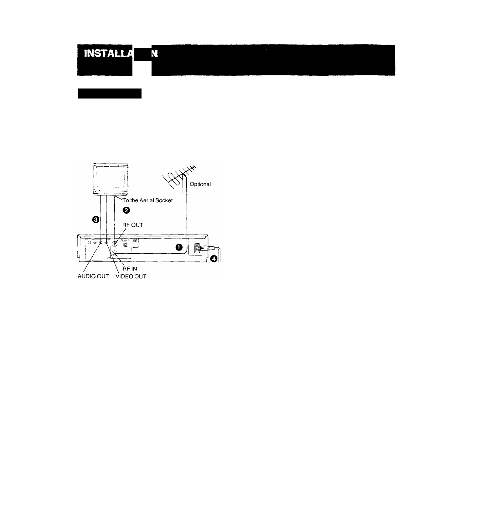
CofmectioiT ta aTV ^
NV-L25A:
FOR YOUR SAFETY
Install any external aerial to AS 1417.1
TV Set
(Select the video channel)
^ Connect the external aerial to the RF Input Socket on
the VTR.
@ Connect the aerial terminal on your TV set to the RF
Output Socket on the VTR with the supplied DIN-DIN
Coaxial Cable.
0 If the TV set is equipped with separate video and audio
input sockets, It is recommended to connect the VTR
to the TV set with separate video and audio cables,
(not supplied)
0 Connect the AC Mains Lead to the AC Mains Socket of
the VTR to the mains outlet.
Page 9

í ^
The adjustments described on this page are not necessary,
if the VTR is connected to the TV set via the Video/Audio
output sockets.
NEL
Q Turn the TV set on and select the programme position
that is not occupied by any TV station.
@ Press the VTR On/Off Switch to turn the VTR On.
(FRONTSIDE)
O
VTR
C O)
• The corresponding indicator lights up.
0 Set the VTR/TV Selector to “VTR".
(FRONTSIDE)
Video Playback Channel Selector
This switch is used to select the Video Playback channel
which is not occupied with any TV station. [NV-L25A: 0 or 1;
NV-L25EA; 2 or 3]
VTR/TV
□
• VTR/TV Indicator will appear in the Multi-Function
Display.
0 Set the Test Signal Switch to “On",
[D
OFF ON
TEST
SIGNAL
0 Tune your TV to VHF channel as shown below.
Confirm by your TV that the received test pattern is as
shown below.
NV-L25A: VHF channel 0 or 1*
NV-L25EA; VHF channel 2 or 3
NV-L25Aonly
*ln some areas
channel 0 may be
used by local TV
station. In this case
switch to channel 1.
0
Set the Test Signal Switch to “Off". Your TV is now
ready to receive the RF output signal from the VTR.
m
OFF ON
TEST
SIGNAL
0 To check, playback a pre-recorded tape and confirm
that the picture quality is satisfactory.
Page 10

The tuner in the VTR makes it possible to receive TV
broadcasts and to record these programmes without having
to turn on the TV set.
CO
\ \
1
o
(D □] a a □
a QC3 □ ac pa
------
□
□
VHF UHF
NV-L25A
NV-L25EA
1 III
0-5 5A-11
1-3
4-11
U
21-69
21-69
The tuner in the VTR can be preset with up to 99 stations.
Q Press the “ + ” or Button until the picture of the
desired station on your TV is satisfactory.
• If the “-f” or ” Button is pressed while pressing the
Next Button, the stations will change quickly.
PRESET PROG
NEXT BAND/AFC
Preparation
• Turn the TV set on and select the programme position
(channel) which you have tuned to the video playback
channel.
• Press the VTR On/Off Switch to turn the VTR on.
• Set the VTR/TV Selector to “VTR”.
0 Press the Preset/Fine/Normal Button.
The indication on the Multi-Function Display changes
from the clock indication to the position indication.
^ Press the Channel Up or Down Button to select a pro
gramme position (channel) which you want to tune to a
TV station.
£) Press the Band/AFC Button to select the “I”, “III” or
“U” position.
r
Display of the programme positions 1 -99
* j : ^
~. **3» i
I i_!
I :
i
! l_! 1
■ iil
During the station search
(The position indication
Tuned condition
flashes on and off.)
• The tuned station is automatically memorized.
Repeat steps 0-0 sach channel you want to tune to a
station.
© Press the Preset./Fine/Normal Button twice.
The indication on the Multi-Function Display changes
back to the previous indication.
RneTunin^ Rroecedure
If fine tuning is necessary, for example for a weak station
which is close to a strong station:
(T) Press the Preset/Fine/Normal Button twice.
L ■ i i
Li ■ ili
/
Indication of the
selected TV band
Press the “-h” or Button to obtain the best tuning
condition.
Selection of the
programme position
• “AFC” Indicator will not be displayed.
• To return the tuning to its former state, press the Band/
AFC Button.
Press the Preset Fine/Normal Button,
;io;
Page 11

CCD r
r- 1 r t n n|i--t \
^ CJU.J tn CE a o o □ oa artaatn
PRESET PROG = 'V- NEXT BAND/AFC CLEAR
--- ------------^------------------------------------
\—^1
: ' □
1 ■ n
Htoteta S^ect the Programme Position (Qiaimei> oir the Remote Controller
1
FINE/NOfiMAL TRACKING
©(D-l-O©
Blanking of Unoccupieti Progr^nme Posltíons^
^ Press the Preset/Fine/Normal Button.
^ Press the Channel Up or Down Button to select a pro
gramme position (channel) which you do not want to
tune to a TV station.
0 Press the Clear Button will be displayed in the
Programme Position Indication).
□ n n □ □ m
(D-*-©
CLEAR
n
• Repeat steps @ and @ for any programme positions
on which no stations are to be tuned. Afterwards,
these programme positions will be skipped during
Up/Down selection of the programme position,
Q Press the Preset/Fine/Normal Button twice.
□ H El
El B
select channel
1-9 m-d] respective channel
10
press button
Cancelling the Dear Functiorr (Blanking>
(T) Press the Preset/Fine/Normal Button.
@ To cancel the blanking of a programme position, select
that programme position on the VTR and then press
the Clear Button.
Press the Preset/Fine/Normal Button twice.
20
11-99
for example 32
If more than 5 seconds pass between the first, second and
third push, the channel will not be changed normally.
11:
F~i->m->r°i
ED-^EZI-*•[!]
Page 12

ECLOC
The built-in digital clock employs the 24-hour system.
□ □
9:10
CHECK
TRACKING
FINE/NORMAL
For Example: Set the clock for Sunday, October 10, 1999,
• Connect the VTR to the mains outlet.
• Press the VTR On/Off Switch to turn the VTR On.
Q When connecting this VTR to the mains or after a long
power failure, the time indications flash.
] [
Q Press the “+” or Button to set the date.
r
t n
-- i IJ
n ■ ! ! i i
^ i_i ' Li O
Press the Next Button,
Press the or “ Button to set the hour.
□ □
□ m
Press the Next Button.
Press the Button to set the minute.
r
\
O'» i IT —
' J-- ! IJ ^
□ □
TRACKING
TRACKING
TRACKING
“A
/
)
vlllillitll«'
z !"! ■ n n p
- U ■ U U V
f !
^ Press the Clock Button to start the date and time set
ting.
i'l n ^
-i ■ \J L
^ Press the “ + ” or ” Button to set the year.
^'3'3c
/,,1'
□ n
□ TO
Q Press the Next Button.
0
Press the “+ ” or " Button to set the month.
^ I |-| iC
^ \ Li “
n ■ r\ P
LI ' LI iJ
Q Press the Next Button.
□ □
CLOCK
□
=
TRACKING
■== “ih
TRACKING
Press the Clock Button
comes exactly 9:10'00".
i
\ ij Q
su
Ci ■ i n
At every push of the Next Button, the flashing indication
changes in the following order,
YEAR^ MONTH-^ DATE^ HOUR-^ MINUTE
-
---------------------------------------------------------------------------
• In case of a power failure, the timer back-up system
maintains the clock operation and timer content for
at least 60 minutes. However, depending on the
charging time and the memory content, the back-up
time may be considerably longer. However, it takes
more than 60 minutes for the back-up circuit to be
come operational, after the VTR is connected to the
mains.
•The Timer Record Function should be set to “Off”,
otherwise the VTR cannot be operated normally. In
this case, the Timer Record Indicator “|T]’' will flash
to warn you.
• During date setting, the corresponding day is si
multaneously set.
• The clock/timer of the VTR is programmed with the
calendar up to the end of the year 2087,
The indications 88-99 are for the years 1988-1999,
The indications 00-87 are for the years 2000-2087,
when the present time
CLOCK
□
be-
J
^
;12)
Page 13
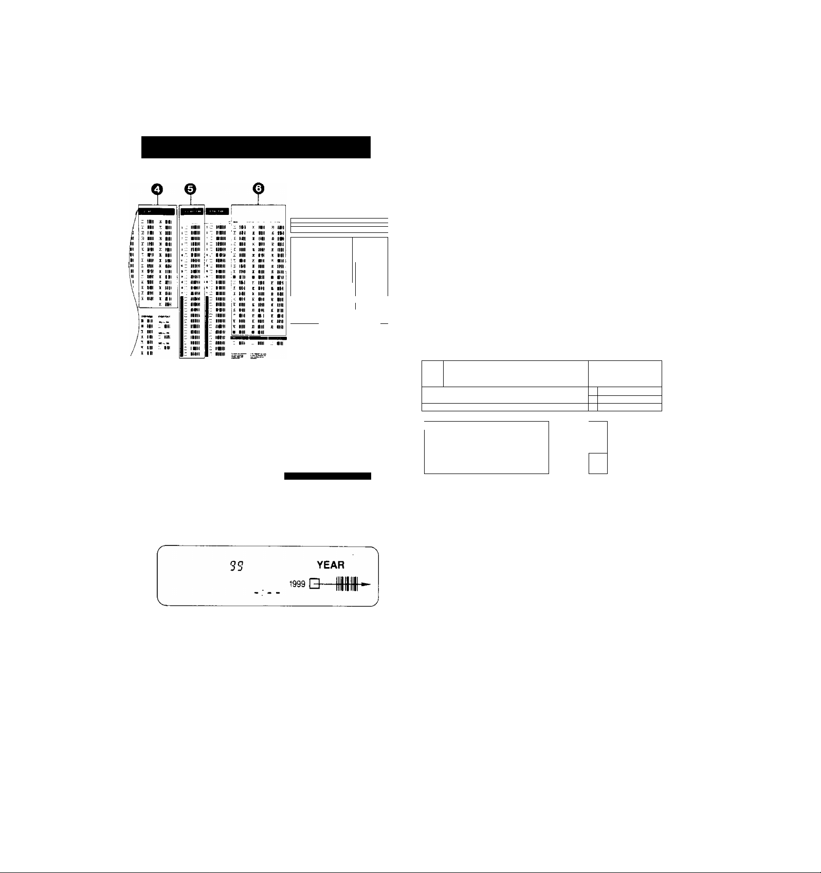
Setting the Dock ta the Time Usin^ the Bar
Codes
0 Trace the bar code for the hour (START TIME),
@ START TIME
3Su 9 B-
^ II
■... m lit , m
lit IM
'■ . til H 1 It i ' nil
'ir" II'1 aM : It
Ill ■: (M in
IB': iti iiii
Ilf ■ ■ H :
■*; lit 111 j : 1 III
j 111 IIMl I 1 II
i ■■ ■ in-
1 ■■ II
' 'iiii
Ill =lir ■ N
_____
' III
' III
■ ml
^ Mil
i ^ ©
Preparation
• Slide down the Mode Selector Cover on the Remote
Controller so that the Bar Code Reader Display can be
seen.
• Press the Digital Scanner On/Off Button to "ON".
O Trace the bar code "SETTING OF THE CLOCK".
SETTING OF THE CLOCK
Q-
0 Trace the bar code for the year (YEAR),
0 Trace the bar code for the month (MONTH).
MONTH
0
Trace the bar code for the minute (MIN).
MIN
n. I n
J- lU
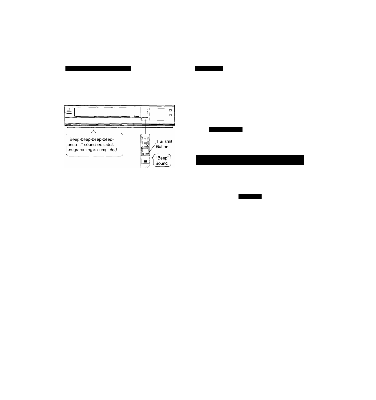
0 Press the Transmit Button on the Remote Controller
and then confirm that the time is displayed in the
Multi-Function Display of the VTR.
CO
s ......................................................
"Beep-beep-beep-beepbeep...” sound indicates that
the time setting is completed.
V_____________________
0
Press the Digital Scanner On/Off Button to "OFF".
• If the transmission was not received correctly, the
"Beep-Beep, Beep-Beep" sound from the VTR will warn
you. In this case, perform transmission again.
• If the Remote Controller is left with no operation per
formed for more than 4 minutes, it will automatically
switch over to the power-saving standby condition and the
lamp in the reading tip goes out. In this case, bar codes
that have already been read (but not yet transmitted to the
VTR) will be cancelled.
•The bar codes "SETTING OF THE CLOCK", "YEAR" and
"MONTH" are located on page 3 of the Programming
Sheet.
...........
./
1^
1
i
r—
T
f
zzA
r..~
o :_r
«f
; □
□
___________
Transmit
Button
"Beep”
Sound
r
n&l—fliMJ
0 Trace the bar code for the day of the month (DATE).
@ DATE
Hi
13
Page 14
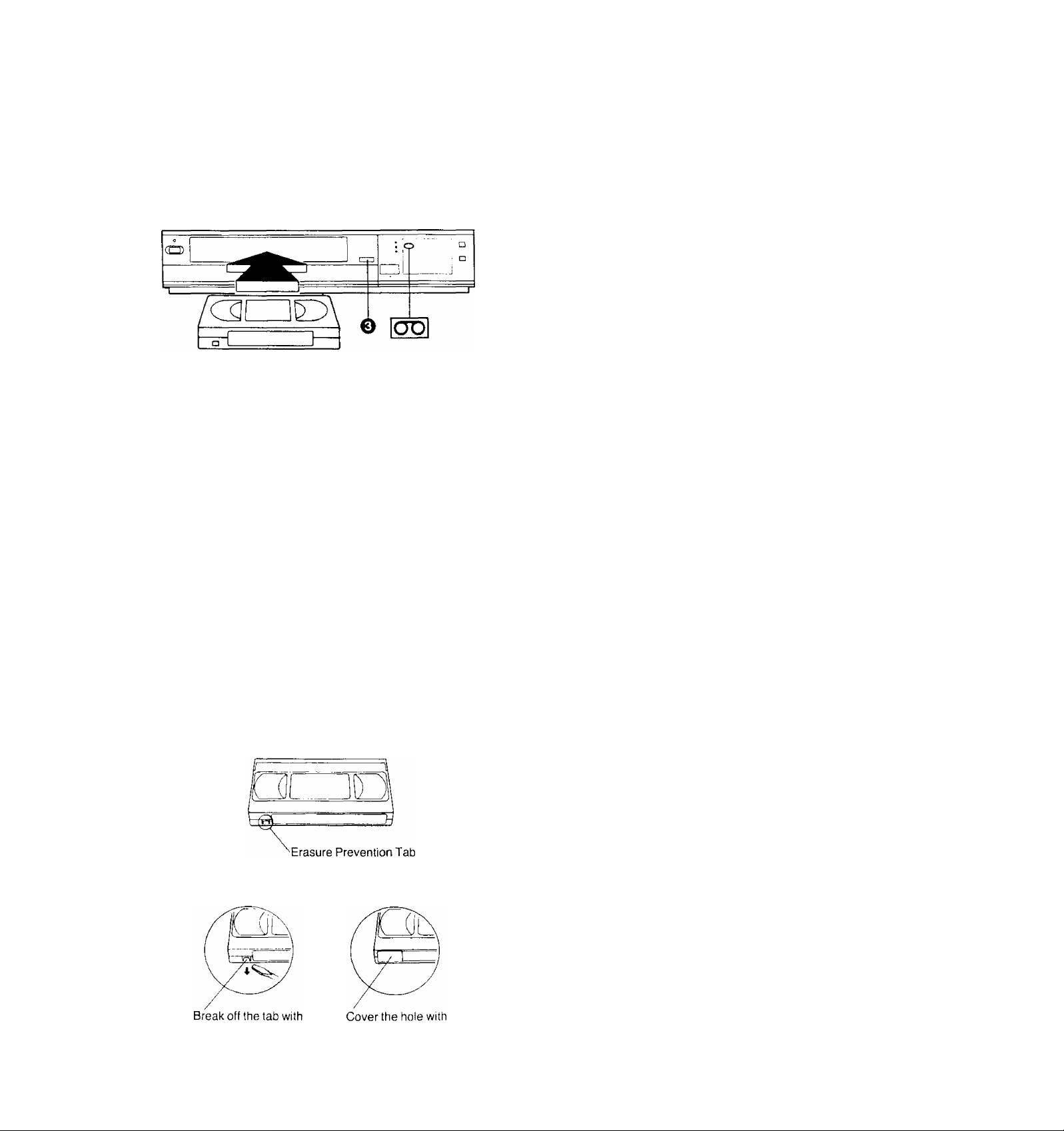
< H1 * J r* fiin J * 1 ^ r. i
^ Insert the video cassette as shown. The VTR will be
turned on automatically and the cassette will be auto
matically drawn into the VTR.
0
When a video cassette is inserted, the “E3” mark will
appear.
Notes;
•When a video cassette with broken out erasure prevention
tab (for example a pre-recorded tape) is inserted, play
back will start immediately.
• Use ;VHSi video cassette tapes only.
Q Press the Eject Button (^).
REJECT
Simply press the Eject Button; the VTR turns itself on,
ejects the cassette and turns itself off again.
Auto VTR On
When a cassette is inserted, the VTR turns itself on auto
matically.
Auto Cue and Play
When inserting a video cassette which has the erasure
prevention tab removed playback will start automatically. If
nothing is recorded on the part of the tape where playback
is started, the VTR will automatically be in the Cue playback
mode until the recorded part is reached, then it changes
back to normal playback mode. When the Search Indicator
is lit, the Cue playback will continue to operate, even after
the recorded part is reached. Therefore press the Play/x2
Button for normal playback.
This applies only to previously unused tapes. Tapes which
have been erased or re-recorded will not exhibit this
feature.
Auto Rewind
When the tape reaches its end during recording (except
OTR and timer recording) or playback, it will automatically
be rewound to the beginning.
Auto Eject
When trying to record on a cassette whose tab is broken
out, the cassette will automatically be ejected to warn that
the recording cannot be made,
VTR-Off Eject
When the VTR is off, the inserted cassette can be ejected
simply by pressing the Eject Button, and the VTR will au
tomatically turn Itself off again.
Rewind Auto Shut Off
When the VTR On/Off Button is pressed during rewinding,
the cassette will be ejected as soon as the beginning of the
tape is reached, and the VTR will turn itself off.
Auto Timer Recording Standby
When the Timer Record Button is pressed during rewind
ing, the VTR will switch over to the timer recording standby
mode after the beginning of the tape is reached.
To prevent accidental
erasure
a screwdriver.
To record again
adhesive tape.
:14>
Page 15

When the Fast Forward ►►/Cue © Button is kept
pressed while the VTR is in the playback mode, the tape
will be played back at high speed in forward direction.
©/FF
PICTURE
®® ®
-□o—
SOFT
Note:
The playback functions Cue, Review, Still, Reverse, Double
Speed and Stow will work only in the SP mode.
Preparation
• Make sure that the Timer Record Function is set to “Off",
• Insert a recorded video cassette.
When a video cassette is already inside the VTR, press
the VTR On/Off Switch to turn it on.
• Turn the TV set on and select the video playback channel.
• Set the Noise Fiiter/Edit Selector to “Off".
• Set the Digital Tracking Switch to “On".
Press the Play/ .v 2 Button (►;
©
SHARP
PLAY/X 2
• Control the picture as you like with the Picture
Sharpness Control (sharp or soft contours).
When the Rewind -<^/Review © Button is kept pressed
while the VTR is in the playback mode, the tape will be
played back at high speed in reverse direction.
REW/e
To make possible Cue or Review playback without having
to keep the respective button pressed, first press the
Memory/Repeat/Search Button on the Remote Controller
so that the Search Indicator ’S" appears in the Multi-
Function Display, and then press the Fast Forward ►►■
Cue I© Button or the Rewind « Review ©) Button,
To switch the VTR back to normal playback, press the
Play/:^ 2 Button (►).
• When Cue or Review playback continues for more than
10 minutes, the VTR wilt automatically switch back to the
normal playback mode.
When the VTR is in the playback mode, press the Play/x2
Button to view the action at twice the normal playback
speed. To change back to normal playback, press the Play/
x2 Button again.
Press the Stop Button
When the VTR is in the playback mode, press the Pause/
Still Button (I I) to view a still-picture. To continue the nor
mal playback, press this button again.
to stop the playback.
PAUSE/STILL
PLAY/X 2
x2
15
Page 16

Using the Remote Controller
When the VTR is in the playback mode, switching over to
Reverse Playback is possible by pressing the Reverse
Playback Button,
• During Reverse Playback, noise bars may appear in the
upper centre and lower centre parts of the picture.
REV. PLAY
Press the Still Advance Button (li^) while the VTR is in the
still playback mode. Each time you press this button, the
still-picture will advance one single field.
STILL ADV
1!SI>
Super Bite Sfcnw Bay baclr
S]
During normal playback, the Slow-motion playback can be
activated by pressing the Slow Button. The slow-motion
playback speed can then be varied by using the Slow “4-”
or Button,
• Press the Play/x2 Button (►) to continue the normal
playback.
• If the Slow playback operation continues for more
than 5 minutes, the VTR automatically switches over
to the stop mode,
• While playing back a tape in the Super Still or Super
Fine Slow playback mode on a TV set equipped with
an automatic vertical hold control, the picture may
shake vertically. In this case, set the TV set's vertical
hold (Auto/Manual) selector to the “Manual” position,
and adjust the vertical hold control.
Slow Tracking Control
• When noise bars appear during Super Still, Super Still
Advance or Super Fine Siow piayback, switch over to
Siow playback and adjust with the Tracking (+) or (-)
Button to reduce the noise bars.
• It may not be possible to eliminate the noise bars com
pletely.
• The sound will be played back only during normal
playback.
• If you leave the VTR in the Stili and Siow playback
mode for more than 5 minutes, the VTR will auto
matically switch over to the Stop mode to protect the
tape and the video heads.
• Noise which takes the form of horizontal bars ap
pears on the TV in the Cue and Review playback
modes. This is not an indication of a malfunction.
• The top of the picture may become distorted in the
Cue, Review or Super Still (LP) mode. This is not an
indication of a malfunction.
• When the picture rolls vertically in the Cue or Re
view mode, adjust the vertical hold control on the
TV set.
• Immediately after starting Cue or Review playback,
the picture may be distorted. Also, when these
modes are cancelled, some momentary picture
distortion may occur. However, this is not due to
any malfunction.
• In “LP” mode only;
1, During any playback mode other than normal
playback, the picture distorted and black and
white. This is not indication of malfunction.
2. When playing back a tape which was recorded
on another VTR, it may be necessary to adjust
the Tracking Control. In some cases the picture
quality may still be inferior. This is due to limita
tion of format.
When changing the slow-motion playback-^
speed, indicator flashes. **■* " '
■ SLOW-
3 CZ3
16)
Page 17

Repeat Playback
; and the Btd oi tti^Tape
^ Press the Memory/Repeat/Search Button so that the
Repeat Indicator ‘"R” lights up.
NTSC Playback
Tapes recorded in the NTSC system can be played back
with this VTR via a PAL system TV set.
•Depending on the TV set used, the picture may shrink
vertically, and black bars may appear both at the top and
bottom of the screen.
This is not an indication of a malfunction.
•And the playback picture may roll up or down, if the TV set
is equipped with a V-HOLD control, it may be possible to
stop the picture movement by adjusting this control.
•The special playback functions (except normal playback)
cannot be used for NTSC recordings. This is not an
indication of a malfunction.
• Recording in the NTSC system is not possible with this
VTR. Insert editing and audio dubbing also would not
function correctly, so please do not operate these func
tions.
0 Press the Play/x2 Button.
•The playback will continue until the end of the tape
At this point, the tape will be rewound to the begin
ning and the playback will be repeated.
0 To stop the Repeat playback, press either the Stop
Button or the Memory/Re peat'Search Button (the Re
peat Indicator "R" will go out).
17;
Page 18

REW/0 — PLAY/X2---------©/FF
iSHSBEB
Press the Rewind ◄◄/Review Q Button to rewind the
tape.
REW/©
Press the Fast Forward
tape forward rapidly.
■/Cue Q Button to wind the
Digital Tracking
ON: Select this position for digital tracking.
When playback is started after inserting a cassette, and the
VTR is turned on, the Digital Tracking function wtil be
activated automatically, the Digital Tracking Indicator will
flash for several seconds, and the tracking will be adjusted
automatically (after the adjustment, the Digital Tracking
Indicator will remain lit).
•When the Digital Tracking Indicator is lit and the tape
speed (SP/LP) is changed, the Digital Tracking function
will be activated. However, when the VTR is operating in
other modes than the playback, insert editing and audio
dubbing, this function will not work.
• During playback, the Digital Tracking function will be
activated whenever the playback changes over from an
unrecorded part to a recorded part, provided the recorded
part is longer than 4 seconds.
»When the picture is distorted by noise bars, press
the Tracking ( + ) or (-) Button to select manual
tracking and adjust with these two buttons. The
Digital Tracking Indicator goes out.
To change back to Digital Tracking, press the
Tracking ( + ) and (-) Buttons simultaneously.
Manual Tracking
OFF; Select this position for manual tracking.
•When the playback picture is distorted by noise bars,
adjust by pressing the Tracking (+) or (-) Button,
•To return the tracking control to the former setting, press
the Tracking (+) and (-) Buttons simultaneously.
©/FF
It shows the elapsed recording or playback time.
Hours
I
■” indication will appear when the tape is
The
rewound further than the tape counter position
‘‘O'.OO.OO’’.
• It the figures on the Tape Counter do not change
during Fast Forward, Rewind or any of the Playback
tunctions, this means that nothing is recorded on
that tape section.
• The Tape Counter is automatically reset to
"0:00.00" when the video cassette is inserted,
• During playback of NTSC recordings, the Tape
Counter does not function correctly.
Minutes
Seconds
.18)
Page 19

m
Repeatedly pressing this button will change the indication in
the following order; “M" {Memory)—^ “R” (Repeat)^ "S”
(Search)^ both indications are off ^ “M”..,
By pressing this button when the VTR On/ Off Switch is set
to “On”, it is possible to change over the display mode of
the Clock/Counter Display in the Multi-Function Display
from “Clock” to “Counter” Display and vice versa.
• Even if the selector button is set for “Counter” the display
• When the Clock/Counter Display shows the time, the
iiiil
Ctock/Oounter Selec;tor
will automatically changes over to “Clock” Display in all
the following cases; When you set the VTR On/Off Switch
to “Off”, adjust the clock to present time, programme a
timer recording, check a timer recording programme or
programme and perform an OTR.
counter cannot be reset and the Memory and Search
Function cannot be activated (“M”, “R” and “S” indication
does not light up.)
EDIT ON: For editing operations such as dubbing.
OFF: For ordinary use of the VTR.
NOISE FILTER ON: For playback of tapes with inferior
picture quality caused, for example, by repeated dubbing.
• When the Noise Filter/Edit Selector is set to “EDIT
ON”, the picture sharpness cannot be adjusted with
the Picture Sharpness Control.
When the Monitor Button is kept pressed during Playback
or Still playback, the broadcast picture of the selected pro
gramme position (channel) or input signal through Audio/
Video Input Socket will be displayed. When this button is
released, the picture will change back to the playback
picture of the tape.
BBIl!
If vertical jitter occurs during Still playback, adjust the VLock Control (on the rear of the VTR) for the corresponding
recording system (NTSC or PAL) with the screw driver, A
one-time adjustment should be all that is necessary,
li
The Memory function makes it simple and fast to find a
certain position on the tape later again, simply by pressing
the Reset Button at that position to set the tape counter to
“0:00.00" and by pressing the Memory/Repeat/Search
Button. During Rewind or Fast Forward, the tape will then
stop at approximately the desired position.
COUNT
M s
Memory Indication
'Even if the Clock/Counter Display is switched over to
“Clock” Display after pressing the Memory/Repeat''
Search Button, the Memory function will stop the tape
at the desired position.
-Search indication
19/
Page 20

Q Select on the VTR, the programme position (channel)
to be recorded. In order to confirm proper reception,
turn on the TV set and select the video playback
channel.
^ Press the Record Button (•).
REC
REC
STOP PAUSE/STILL
REC
0 o e
RECORDING
□
SP/LP
Preparation
• Make sure that the Timer Record Function is set to “Off".
• Reset the Tape Counter to “0:00.00".
• Insert a video cassette with the erasure prevention tab
intact.
When a video cassette is already inside the VTR, press
the VTR On/Off Switch to turn it on.
• Set the Tape Speed Selector to“SP" or“LP".
• Set the VTR/TV Selector to “VTR”.
For recording either of two tape speeds can be selected.
During playback the recorder selects automatically the
correct speed.
Select the desired tape speed with the Tape Speed Selec
tor before recording.
• Set to the “SP” position for normal speed.
• Set to the “LP" position for slow speed. The correspond
ing indicator {SP or LP) lights up during recording and
playback in the Multi-Function Display.
--------------------------------------------------------^
It is not recommended to change from the SP to the
LP mode or vice versa in the middle of recording.
Even if the switching is done while the VTR is in the
pause mode, picture distortion will occur at the
switching point during playback.
* •
When a video cassette with broken out tab is inserted, it will
be ejected automatically.
• During recording, the programme position (channel) on
the VTR cannot be changed.
• To start a recording with the Remote Controller, press the
two Record Buttons on the Remote Controller simulta
neously.
Ta HnisiTthe RecorcUng
0 Press the Stop Button (I
Avoid Recording Unwanted Material
0 Press the Pause/Still Button (| I) to stop the tape tem
porarily.
PAUSE/STILL !
II
• Press the Pause/Still Button (II) again to continue the
recording.
• If you leave the VTR in the pause mode for more than
5 minutes, the VTR will automatically switch over to the
stop mode to protect the tape and the video heads.
1. Record (following steps Q ^nd @).
2. Set the VTR/TV Selector to “TV”.
3. Select the desired programme position (channel) on
your TV set.
/--------------------------------------------------------------------------------
• Disconnect all cables from the Video input and Au
dio Input Sockets before starting the recording. If
they remain connected, it is impossible to record TV
programmes.
•If pause is activated during record and the released,
some colour noise may be present for a short period
of tape, this is not a muifunction.
REC
20)
Page 21

This convenient function makes it possible to easily pro
gramme the VTR for recording of TV programmes with im
mediate start or with start within 24 hours by precisely
setting the starting time and ending time to the desired
minute, and the VTR will automatically turn itself off when
the recording ends.
0 e e
PROG
1 I
Preparation
• Make sure that the clock shows the present time correctly.
• Insert a video cassette with the erasure prevention tab
intact.
When a video cassette is already inside the VTR, press
the VTR On/Off Switch to turn it on.
• Set the Tape Speed Selector to "SP” or “LP”.
It is possible to programme an OTR recording for a TV
programme which will start immediately or within the next
24 hours.
(For example. OTR recording of a TV programme broad
cast from 10,30 to 11 ;00.)
^ Select the programme position (channel) to be re
corded.
^ Press the OTR On (-h) or (-) Button to set the OTR
starting time to 10:30.
0
Press the OTR Off (-t-
ending time to 11:00.
• When quickly and repeatedly pressing the OTR On {+) or
{-) Button or the OTR Off (-h) or (-) Button, the corre
sponding time indication changes in 1-minute steps.
When it is kept pressed, the indication changes in
10-minute steps.
• After setting the OTR starting time in step the OTR Off
(-F) or (-) Button must be pressed within 8 seconds to
select the OTR ending time, otherwise the selected start
ing time will be cancelled.
After 4 seconds, the display will automatically change back
to the starting time indication,
To confirm the OTR ending time, press the Check/Programme Button once. When this button is pressed twice,
the display will change to the clock indication mode.
J
SP
or (-) Button to set the OTR
1 n
1 \J D
n n
L! U
PROG
□
02^0
I ON—'[oil
SP ON
• The “OTR ’ indicator will be displayed.
When a video cassette with broken out tab is inserted, it will
be ejected automatically.
-h
•The VTR will automatically switch off, when the OTR is
completed. To turn the VTR on again, press the VTR
On/Off Switch.
2i:
Page 22

When the Check/Programme Button is pressed once, the
present time will be displayed.
a
OTR IRK I
111
i u
№
When the Clock/Counter Selector Button is pressed during
OTR recording, the display will change over to the counter
mode.
i U D
Q ■ i i-i
-! ■ I U:
PROG
□
o
PROG
□
Q Select the programme position (channel) to be re
corded.
^ Press the OTR Off (+) or (-) Button to set the OTR
ending time to 11:00.
• When the tab of the inserted video cassette is broken
out, it will be ejected automatically.
•The “OTR” indicator will be displayed.
• The VTR will automatically switch off, when the OTR is
completed. To turn the VTR on again, press the VTR
On/Off Switch.
a
iHSCI
CLOCK/COUNTER
SP
n • i“i i“I i”i n
L! ■ i_i iJ. i-i i_i
• When the tape reaches its end during an OTR the
VTR will turn itself off.
• Make sure that the OTR Function (One-Touch
Timer Recording) does not overlap a programmed
timer recording. An OTR always takes precedence
over a timer recording.
• It is possible to change the OTR starting time or the
ending time before the recording starts.
• It is possible to perform any VTR operation (except
timer recording) until the recording starts.
• It is possible to change the OTR ending time even
during the recording.
• To interrupt an OTR, press the VTR On/Off Switch
to turn the VTR off.
• Disconnect all cables from the Video Input and Au
dio Input Sockets before starting the recording. If
they remain connected, it is impossible to record TV
programmes.
□
22;
Page 23

The programming of timer recordings is possible both on
the VTR itself and via the Remote Control Unit,
Programming of as many as 8 timer recording is possible
up to one month in advance.
0 Press the (-k) or (-) Button to select the programme
position (channei) on which the TV programme will be
broadcast.
□ □□□□□□
TRACKING
Preparation
• Make sure that the clock shows the present time correctly.
• Make sure that the Timer Record Function is set to ‘'Off'.
• Insert a video cassette with the erasure prevention tab
intact.
When a video cassette is already inside the VTR, press
the VTR On/Off Switch to turn it on.
For Example;
Programming a timer recording for a TV programme that
will be broadcast on Wednesday, October 27. from 10:30 to
11:45, on programme position (channel) 12, on timer pro
gramme number 2. (Present date-^ October 10, 1999)
^ Press the Check/Programme Button to select the next
unoccupied timer programme number.
• Press the Tape Speed Selector Button until the indi
cator of the desired tape speed (“SP " or "LP ") is lit in
the Multi-Function Display.
PROG
E
>! iV
a
SP DN
0
Press the Next Button.
Q Press the (-k) or (-) Button to set the date.
-I
i- -C‘
SP ON
0
Press the Next Button.
Press the (-k) or (-) Button to select the hour of the
starting time of the TV programme.
! i
=■ Hk
□ □
TRACKING
] □
TRACKING
I c
SP -
t
n □
TRACKING
-4iv^
Q Press the Next Button.
Q Press the ( + ) or (-) Button to select the minute of the
starting time of the TV programme.
SP
CHECK
SP ON
--------
@ Press the Next Button.
:23.
vL.
= -Ik
□ □
TRACKING
Page 24

0 Press the ( + ) or (-) Button to select the hour of the
end time of the TV programme.
! "1
2
SP
3 3
L i B
= ■*■
□ □
TRACKING
'I 1^:1 Ci
Press the Next Button.
0
Press the (+) or (-) Button to select the minute of the
end time of the TV programme.
Rjr Ev«»^ v№ek Fl^cordlng
For Example:
Programming a timer recording for a TV programme that is
broadcast every week on Sunday, from 10:30 to 11:45 on
timer programme number 7.
Programming for everyweek recording can be made on any
of the timer programme numbers 1-8,
Execute the operation steps 0 to ©.
Q Press the (-) Button repeatedly until the “SU” Indica
tor (^Sunday) is lit.
i *****
I *****
C i D
SP OFF
0
Press the Timer Record Button.
□ □
TRACKING
7 ;SU ;
SP ON
Perform the operation steps 0 to (B.
I g № jTvi; f-4 >7« j t* m
m
For Everyday Recording, you have the choice between
3 different modes: Monday through Friday, Monday through
Saturday, and Sunday through Saturday.
MOTUWETHFR--------
□ □
TRACKING
<D
MOTUWETHFRSA — SUMOTUWETHFRSA
For example:
Programme time for timer recording every day from 10:30
to 11:45 on timer programme number 8.
Programming for everyday recording can be made on any
of the timer programme numbers 1-8.
Execute the operation steps O ©■
Q Press the (-} Button until the desired type of Everyday
Recording ((T), (g), @) is displayed.
1 c
8 ' SUMniWEmFHU Z
SP ON / T11 ? f t T TIT r >
Perform the operation steps 0 to
24)
TRACKING
Page 25

Make sure that the VTR is turned on.
Make sure that the Timer Record Function is set to “On”.
Select the programme number to be checked, by repeated
ly pressing the Check/Programme Button.
The preset channel and start and ending times of the timer
recording will be indicated for about 12 seconds.
SP 0«
(start time)
PROG
(4 seconds) j I
CHECK
2
SP
(end time)
Make sure that;
the VTR is turned on,
the Timer Record Function is set to “Off”.
Press the Check/Programme Button repeatedly, until
the number of the timer programme that you want to
cancel is displayed.
@ Press the ( + ) and (-) Buttons simultaneously for more
than 3 seconds.
OFF
=~i (next 8 seconds)
i\iT$
•After the programmed timer recording has been
made, set the Timer Record Function to “Off", oth
erwise the VTR cannot be operated normally.
• During recording, the programme position (channel)
on the VTR cannot be changed.
• When you want to watch TV after setting a timer
recording, select the desired channel on the TV set.
• To cancel a timer recording during recording, set
the Timer Record Function to “Off”.
• It is impossible to confirm programmes of timer re
cordings while an OTR is being performed.
•To turn the VTR on and use it for playback or re
cording before the timer recording is performed, set
the Timer Record Function to “Off".
• When the Timer Record Function is set to “On” but
no video cassette is inserted or no timer recording
has been programmed, the Timer Recording Indi
cator [2 will flash to inform that the timer recording
cannot be performed.
• If no cassette is inserted in the VTR, the “isg” Mark
will flash.
• Disconnect ail cables from the Video Input and Au
dio Input Sockets before starting the recording. If
they remain connected, it is impossible to record TV
programmes.
■25/
Page 26

Timer Recording by Using the Remote
Controller
0 Trace the bar code for “END TIME",
r 11
ON
1 - n
( UL
Trace the bar code for “MIN'
1
I
J D
OFF
~t • n n ^ Q"
I ■ u u
@ END TIME
mu
mu
HIU
1 m
tJM
f\\ a 9 \ a II
*\\\i
turn
iflll
mii
im
UHllP
Mill*
lillt
miiii
iMIii
IIIIM
mio
iHlll
m\ii
3I«IM
a V\ o lU
«ini'
iiui
iiifii
Example: When programming a timer recording for a pro
gramme that will be broadcast on channel posi
tion 4 on the 3rd of the month, from 7:02 to 7:30,
trace the bar codes in the order of the numbered
arrows shown below.
Press the Digital Scanner On/Off Button to “ON”.
Q Trace the bar code for “CHANNEL”.
ON
U
I
D
OFF
© CHANNEL
B-
I i
t
J D
ON
~t n “i
V » u C
• The “Bee Bee Bee Bee Beeeeep" sound signals
that the scanner is now ready for data transmission.
• When no sound is heard, read the bar codes once
again.
• If more than one bar code is read in the same
group, only the last code will be effective.
• If the “CANCEL” bar code is read, all bar codes that
have been read so far wilt be cancelled.
OFF
n nn
t • D U
MIN
@ Trace the bar code for “DATE'
I /
I
J D
ON
Q Trace the bar code for “START TIME".
I t
I
OFF
J D
ON OFF
inn _ 7 Q
I uu
Q Trace the bar code for “MIN”.
U
I
3 D
ON
1 ni
y t uc
OFF
® DATE
^ START TIME i
MIN
.26^
Page 27
Transmltttm Pm^^urtming Efatat
Keep pressing the Transmit Button and confirm that the
programmed data on the Multi-Function Display of the VTR
are as desired.
After releasing the button, the data will continue to be dis
played for about 12 seconds.
Timer On/Off
After programming a timer recording, the VTR is in the timer
recording standby mode and cannot be used for any other
operation, such as playback. If some other operation is
desired, first trace the “TIMER ON/OFF" bar code and
transmit it to the VTR with the Transmit Button.
To later reset the VTR to the timer recording standby mode,
trace the “TIMER ON/OFF" bar code again and transmit it
with the Transmit Button,
r
TIMER ON/OFF
B
r
L
For P^f^raffimtng More ITtmOneTIni^RecxiixIhig tit Soccessior»
• If the transmission was not received correctly, the
“Beep-Beep, Beep-Beep" sound from the VTR wilt warn
you. In this case, perform transmission again.
• The transmission is possible when the VTR is turned on
but is not in any of the recording or playback operation
modes. It is also possible when the VTR is in the timer
recording standby mode (g indication is lit).
•The programming will be done on the next lower unoccu
pied timer programme number (8~ 1).
• If all programme numbers are occupied, the “Beep-Beep,
Beep-Beep’’ sound from the VTR will warn you that the
programming cannot be made.
• When the Transmit Button is pressed, the VTR will auto
matically be put into the timer recording standby condition
and the VTR will be turned off.
• To operate the VTR before the timer recording will be
performed, press the Timer Record Button to suspend the
timer recording standby condition. After using the VTR, be
sure to press the Timer Record Button again, otherwise
the timer recording will not be made.
Repeat the following operation steps 0~©'
Q Trace the “CANCEL” bar code on the Programming
Sheet.
CANCEL
* •
B-
@ Trace the bar codes for “CHANNEL”, “DATE”,
“STARTTIME" and “END TIME”.
0
Confirm that the present time is displayed on the
Multi-Function Display of the VTR, and transmit the
data.
• If the next timer programming data are transmitted
while the previous timer programming data are still
being displayed, the displayed timer recording data
will be cancelled.
27:
Page 28

■■HPPOT
umi
For Evc»ryday Recordiriig
ER RECORDING (CO
0 Trace the “START TIME” and then the “END TIME”
bar codes, and transmit the data to the VTR.
When programming an everyday recording using the bar
codes, you have the choice between 3 different modes:
Sunday through Saturday, Monday through Friday, and
Monday through Saturday.
(T) Turn on the Digital Scanner and trace the “CHANNEL"
bar code.
@ Trace the desired “EVERYDAY” bar code (0, @, 0).
r
(SU~SA)
Trace the “START TIME” and then the “END TIME”
bar codes, and transmit the data to the VTR.
• Everyday recording will be performed from that day on.
• If a “DATE” bar code is traced after tracing the
“EVERYDAY” bar code, everyday recording will not be
performed.
ForEveryweek Recording
Q Turn on the Digital Scanner and trace the “CHANNEL”
bar code.
^ Trace the bar code for the desired day of the week
among the “EVERYWEEK" bar codes.
SU MO TU WE TH FR SA
ON
SU MO TU WE TH FR SA
ON
■uu
8
nn
OFF
OFF
m nn
• uuu
EVERYWEEK
Sunday
Monday
------------
11
HIaI
SU
S
ON
jn nn
Cu uu
• Everyweek recording will be performed from that week on.
• If a “DATE” bar code is traced after tracing the “EVERY
WEEK" bar code, everyweek recording will not be per
formed.
Ta Confirm tim Programme of a Timer Recording
To perform this operation, the VTR must be turned on or it
must be in the timer recording standby mode ([T] indication
is lit).
(T) Trace the “CHECK” bar code.
• After releasing the Transmit Button, the programmed
data will be displayed for about 12 seconds (for about
25 seconds, if the [i] indication is not lit) on the
Multi-Function Display.
• At every push of the Transmit Button, the timer pro
gramme number advances to the next higher num
ber.
ToCaitcef a Programmed Timer Recording
To perform this operation, the VTR must be turned on but
not be in any of the recording or playback operation modes,
or it must be in the timer recording standby mode (□ indi
cation is lit). To cancel a programmed timer recording, its
data must be displayed on the Multi-Function Display. If
they are no longer displayed, first, trace the “CHECK” bar
code and perform transmission (several times, if necessary,
until the programme you want to cancel is displayed). Then,
within 12 seconds.
0 Trace the “CANCEL” bar code.
0 Perform transmission.
• To programme a new timer recording, perform the
programming from the beginning.
OFF
cc
nn
uu
1 U€5Gcy ■" — "
Saturday
-----------------
------------
-irul
iriil
LliU
fral
®
lly
■28)
Page 29
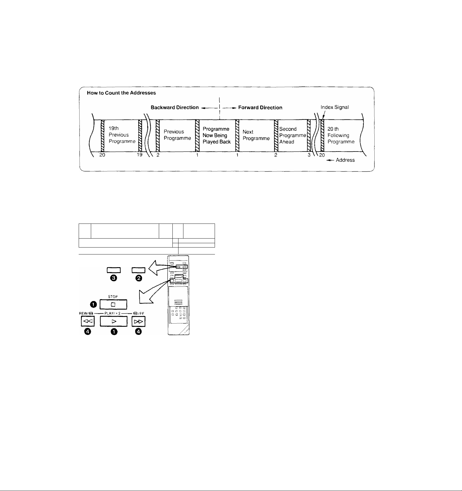
With the VHS Index Search function, up to 20 addresses
{places where index signals are recorded) can be skipped
to directly locate the beginning of the desired progrannme in
both forward and reverse direction in the Fast Forward or
Rewind mode.
CO
T
_____________- _____________________________________:______________
RESET/ MEMORY/
INDEX REPEAT/SEARCH
CZl
:
Hi 1
r
i a
1 D
J
^ Press the Play/x2 Button (►) or Stop Button (■).
e Press the Memory/Repeat/Search Button.
• The indication “S" appears on the Multi-Function
Display.
0 Repeatedly press the Reset/Index Button to select the
desired address.
The number of the selected address is shown on the
Multi-Function Display.
^ Press the Rewind •M/Review @ or Fast Forward
►►/Cue © Button to start the VHS Index Search
function (the VTR will switch to the rewind or fastforward mode).
• Every time an index signal (address) is skipped the num
ber in the Address Indication decreases by one.
• When the preset address is reached, the Tape Counter
Indication will appear in place of the Address Indication,
and the normal playback will start.
•To abort the Index Search function midway, press the
Play/x2 or the Stop Button.
Recording of Index Signals
Index signals will be recorded automatically in the following
cases:
•At the tape position at which the Record Button is pressed
to start recording.
•At the tape position at which a Timer Recording is started.
•At the tape position at which an OTR recording is started.
f »When activating the VHS Index Search function ^
from the Still playback mode, the playback will start
when the selected programme is reached.
• If the VHS Index Search function is started ex
tremely dose to the beginning of the next pro
gramme (place where an address signal is
recorded) or from the beginning of the tape, the first
address may not be counted.
• if there are unrecorded parts on the tape, or if re
cordings have repeatedly been made on the same
tape portion, the VHS Index Search function may
not work correctly.
'29;
Page 30

How the Intro Scan Function Works...
Tape is
The Intro Scan function plays back the first 10 seconds of
each programme (recorded with index signal) on a tape one
after another. This is convenient for quick checking what
programmes are on a tape, or to find the desired instalment
of a TV series you have recorded on a tape.
Playback for about
10 seconds
•The Intro Scan function may not be activated for the
first programme recorded close to the beginning of
the tape.
• During the Intro Scan, if there is a portion without
any recording on the tape, the Intro Scan function
will be activated at that position to play back the
tape for about 10 seconds, and the Intro Scan will
then continue.
• The Intro Scan function may not be activated, if the
interval between programme starts is less than
5 minutes in the LP mode, or less than 2 minutes in
the SP mode.
^ Insert a video cassette.
(Put the VTR in the stop mode.)
Q Press the Memory/Repeat/Search Button.
(“S” mark appears.)
o Press the Fast Forward ►►/Cue © Button.
(The Intro Scan starts.)
Q When the desired scene is reached, press the Play/x2
Button twice.
30/
Page 31

TIME SEARCH
The Time Search function makes it possible to quickly
advance the tape from any position by inputting the exact
desired amount of playback time of the part that you want to
skip.
'Present position
10.00
10 minutes from
beginning of tape.
15.43
15 minutes
43 seconds from
beginning of
tape.
Q Press the Fast Forward ►►/Cue © Button or the
Rewind -<^/Review © Button.
The playback starts after rewinding or fast forwarding
to the tape position of the designated time.
Time Seaix;hfrom the Play Moder
The operation is the same as that for the stop mode but in
operation step Q, the Cue or Review (playback) is per
formed to the tape position of the designated time and the
playback will then start.
If the time search function is activated during playback, a
time of up to 9 minutes 59 seconds can be input.
• The numbers in the Tape Counter do not change
during parts of the tape on which there is no re
cording.
•When the tape is inserted, the Tape Counter will
automatically be reset to “0:00.00".
•When no time is input for the time search, a
2-minute tape segment is skipped and the playback
will then resume.
If the time search function is activated during play
back, but no time is input, a 30-second tape seg
ment will be skipped and the playback wilt then
resume.
Q Put the VTR in "STOP" mode.
o Press the Time Search Button.
The indication in the Multi-Function Display changes
as shown below.
COUNT
Input the time of the desired scene.
©
• The time is input by pressing the number buttons in
the order; hour, minute, second.
• The ■■ " indication will be counted as “0".
COUNT
(31/
Page 32

CAMERA RECORDING
• If you leave the VTR in the pause mode for more
than 5 minutes, the VTR will stop automatically to
protect the tape and the video heads.
• Even if the video camera is equipped with video
recorder remote control functions, this VTR can not
be remote-controlled from the camera.
•Disconnect all cables from the Video Input and
Audio Input Sockets after finishing camera record
ing.
If they remain connected, it is impossible to record
TV programmes.
Preparation
• Connect the Video Camera via the Camera AC Adaptor to
the VTR as shown in the illustration above.
• Insert a video cassette with the erasure prevention tab
intact.
When a video cassette is already inside the VTR, press
the VTR On/Off Switch to turn it on.
• Set the Tape Speed Selector to “SP” or "LP”.
Q Turn the Camera AC Adaptor on and make the nec
essary adjustments on the camera.
Refer to the operating instructions of the camera you
are using.
^ Press the Record Button (•) on the VTR to start re
cording.
Avoid recording unwanted material:
Press the Pause/Still Button {II) on the VTR, and the re
cording will stop temporarily. To restart recording, press the
Pause/Still Button (I I), again.
0 Press the Stop Button (■) on the VTR to stop the
recording.
32)
Page 33

DUBB
Dubbing (copying) from one video cassette to another.
AUDIO IN VIDEO IN
• To assure smooth, noiseless cuts when interrupting
the recording, always use the Pause/Still Button
(II).
• To obtain smooth cuts when starting the recording
from the stop mode:
1. Play back the last part of the previously recorded
material to confirm its ending point, and then
press the Pause/Still Button (II).
2. Press the Record Button (♦).
(The VTR is still in the pause mode.)
3. To start recording, press the Pause/Still Button
(II) again.
•The picture quality of a re-recorded tape is not as
good as that of the original.
• Disconnect all cables from the Video Input and Au
dio Input sockets after finishing the recording. If
they remain connected, it is impossible to record TV
programmes.
Preparation
• Make the necessary connections as shown in the connec
tion diagram.
• Press the VTR On/Off Switches to turn both VTRs on,
• Make sure that the Noise Filter/Edit Selector of both the
recording and playback VTRs (if equipped) are in the
“EDIT ON” position. Set these switches to “OFF” for or
dinary use of the VTRs.
(The Noise Filter/Edit Selector is on the front panel.)
^ Place the recorded cassette in the playback VTR and a
blank video cassette with the erasure prevention tab
intact in the recording VTR.
^ Press the Record Button (•) on the recording VTR,
0 Press the Play/x2 Button (►) on the playback VTR.
0 Press the Stop Button (■) on both VTRs to stop the
dubbing.
(33;
Page 34

NG)(CO
Connecting to a VHS/VHS-C Movie Equipped with S^chm Edit Functioit
It is possible to synchronize the playback start and stop of
the VHS/VHS-C Movie with the recording start and stop of
this VTR.
Preparation
• Make the necessary connections as shown in the con
nection diagram.
• Set the Edit Switch (Noise Fiiter/Edit Selector) on both the
VHS/VHS-C Movie and on this VTR to “ON” (or “EDIT
ON”).
^ Put the VTR in the recording pause mode.
@ Put the VHS/VHS-C Movie in the still playback mode.
• Put the Movie at the point where you want to start
editing into the still playback mode.
Q Press the Pause/Stil! Button on the VTR.
• The VHS/VHS-C Movie changes over to the playback
mode and the dubbing will start automatically.
* •
!»i
(J) Press the Pause/Still Button on the VTR.
• The VTR changes over to the recording pause mode
and the VHS/VHS-C Movie changes over to the still
playback mode.
Operate the VHS/VHS-C Movie to skip the unwanted
scenes and then put it in the stilt playback mode again.
Press the Pause/Still Button on the VTR.
•The dubbing will restart.
To stop the dubbing, press the Stop Button on the VTR and
then put the VHS/VHS-C Movie in the stop mode.
:34)
Page 35

Insert Editing is an editing system that allows replacing
scenes on a previously recorded tape by newly recorded
scenes or titles.
It is possible to record new sound at the same time.
eo
Preparation
• Connect the systems needed for the Insert Editing.
• Insert a Video cassette with the erasure prevention tab
intact.
• When performing insert editing from another VTR. set the
Noise Filter/Edit Selector to '‘EDIT ON",
Q Press the Play./x2 Button,
o Locate the tape position where you want the insert
editing to end, and press the Pause/Still Button to put
the VTR into the still playback mode.
Q Press the Memory/Repeat/Search Button on the Re
mote Controller so that the Memory Indicator “M” mark
will light up.
0 Perform review playback to a point the insert editing
start point.
Q Press the Insert Editing Button.
(The Insert Editing Indicator lights up.)
To simultaneously insert new sound, press the Audio
Dubbing Button.
(The Audio Dubbing Indicator will light up.)
Q After the picture to be inserted is prepared, press the
Pause/Stiil Button (I |).
(The insert editing will start.)
• The insert editing will end at the point where the Tape
Counter indicates “0:00.00". and the editing VTR will
stop in the still playback mode.
• It is not necessary to operate the Tape Speed Se
lector.
• The picture quality of an inserted part is always
somewhat inferior to that of the original.
• Avoid performing insert editing repeatedly on the
same part of the tape because the picture quality of
that part becomes inferior,
• Do not press the Memory/Repeat/Search Button
during insert editing. If it is pressed, the Memory
Indication “M” will disappear, and the insert editing
will not end automatically at the preset editing end
point.
• The inserted picture may contain slight colour noise
or the colours may be unstable.
• If insert editing is performed on a tape recorded in
' the NTSC system, the insert editing function will not
1 work correctly.
V______________________________________________
0 Press the Reset Button to reset the Tape Counter to
‘■0:00.00’,
;35)
Page 36

BBi
r\
Note that the original sound will be completely erased dur
ing audio dubbing.
o e eo
Preparation
• Insert a video cassette with the erasure prevention tab
intact.
When a video cassette is already inside the VTR, press
the VTR On/Off Switch to turn it on.
• Reset the Tape Counter to ‘‘0:00.00”.
•Turn the TV set on and select the video playback channel.
Press the Play/x2 Button (►) to locate the point where
o
you want to start the audio dubbing.
Press the Pause/Still Button (II) at the exact point
0
where you want to start the audio dubbing.
Press the Audio Dubbing Button (the indicator will light
0
up).
AUDIO DUB
AUDIO DUB O
□
Q Press the Pause/Still Button (I I) once again to release
the tape from pause, and at the same time start the
operation of the audio source. The audio dubbing will
start.
0
Press the Stop Button (■) to stop the audio dubbing.
• When a microphone is used for dubbing, do not
place it near the speaker of your TV to prevent
howling noise (acoustic feedback).
• if the erasure prevention tab of the cassette is
missing, no audio dubbing can be made.
• if audio dubbing is performed on a tape recorded in
the NTSC system, the audio dubbing function will
not work correctly.
* •
J
/36)
Page 37

Before requesting service, check the following points once
again.
SYMPTOM CAUSE
Power doesn't turn on.
Power is on but unit doesn't
operate.
TV programmes cannot be
recorded.
OTR Function {One-Touch Timer
Recording) cannot be performed.
Unattended timer recording
cannot be performed.
REMEDY
Mains lead is not connected.
The Timer Record Function is set to “On".
Dew condensation inside the VTR.
Safety devices are operating.
Connect mains lead tcrmains outlet.
Set the Timer Record Function to “Off".
Wait until the Dew Indicator “d " goes off.
Turn off the VTR On/Off Switch, disconnect
mains cord from outlet, then reconnect mains
cord to mains outlet and turn on the VTR
On/Off Switch again.
Connectio'n of aerial lead is not correct. Connect aerial lead correctly.
Reception channel is not properly tuned.
Cables are connected to the Video Input and
Audio Input Sockets.
Clock is flashing ‘‘0:00’’.
Recording start or recording stop time setting
is incorrect.
The Timer Record Function is set to “Off".
Tune reception channel.
Disconnect ail cables from the Video input and
Audio Input Sockets.
Set clock to present time.
Set recording start and recording stop time
correctly.
Set the Timer Record Function to “On”.
If you attempt to carry out
Recording, Timer Recording,
or OTR, the cassette will be
automatically ejected.
Clock shows incorrect time.
Clock is flashing at “0:00”.
Accidental erasure prevention tab on the
cassette is broken out.
Adjust clock to present time.
Set clock time and perform timer setting.
Cover tab hole with adhesive tape.
37
Page 38

SYMPTOM
CAUSE
REMEDY
Playback picture is not in colour.
Playback picture has large
amounts of “snow”.
Remote Controller does not work.
Bar code reading with Remote
Controller is impossible.
Reception channel was not adjusted correctly
during recording.
TV set is not properly tuned to the video
playback channel of the VTR.
The video heads are clogged with dirt.
The video heads are abraded.
Tape is old and/or defective.
Remote Controller is not being pointed at
Infra-red Receiver Window on the VTR.
Distance is too far.
An obstacle is between Remote Controller
and VTR,
Batteries are exhausted.
Battery polarities ( + , -) are reversed.
The Remote Controller is in the power-saving
standby condition.
Readjust reception channel correctly.
Properly tune the TV set to the video playback
channel of the VTR.
Consult qualified service personnel.
Consult qualified service personnel.
Use new tape.
Point the Remote Controller at Infra-red
Receiver Window on the VTR.
Use the Remote Controller within 7 m from the
VTR.
Remove obstacle.
Replace batteries.
Insert batteries correctly.
Press the Digital Scanner On/Off Button to
“ON” again.
Transmission from the Remote
Controller to the VTR cannot be
performed.
The bar code has been traced too slowly.
The bar code was not traced all the way from
the Small Box past the last bar.
The bar code was not traced straight.
The VTR is turned off.
The VTR is in an operation mode.
There is no unoccupied timer programme
number left.
Reading a bar code was not followed by a
“beep” sound from the Remote Controller.
The transmission was not followed by a
repeated “beep” sound from the VTR,
Trace the bar code quickly.
Trace the bar code correctly.
Trace the bar code straight from left to right.
Turn the VTR on.
Put the VTR into the stop mode.
A maximum of 8 timer recordings can be
programmed at the same time.
Perform the bar code reading again.
Keep pressing the Transmit Button until the
confirmation sound is heard.
38;
Page 39

SPEC
NV-L25A, EA
Power Source:
Power Consumption:
Video Recording System: Video Heads:
Tape Speed;
Tape Format:
Record/Playback Time:
FF/REW Time:
VIDEO
Television System:
Modulation System:
Input Level:
Output Level:
AUDIO
Input Level:
Output Level:
Audio Track:
Video Horizontal Resolution:
Signal-to-Noise Ratio:
Audio Frequency Response:
Operating Temperature:
Operating Humidity:
Weight:
Dimensions:
Standard Accessories:
240 V AC 50-60 Hz
Approx. 22 watts
2 rotary heads, helical scanning system
4 heads
SP; 23.39 mm/sec.
LP; 11.7 mm/sec.
VMS tape
SP; 240 min. with NV-E240
LP; 480 min. with NV-E240
Less than 5.5 min. with NV-E180
CCIR; 625 lines. 50 fields, PAL colour signal
Luminance; FM azimuth recording
Colour signal; converted subcarrier phase shift recording
VIDEO IN (PHONO); 1.0Vp-p,
VIDEO OUT (PHONO); 1.0 Vp-p,
RF Modulated: NV-L25A: VHF channel 0 or 1,
NV-L25EA: VHF channel 2 or 3,
AUDIO IN (PHONO);
MICROPHONE;
AUDIO OUT (PHONO):
1 track (Normal-mono only)
Colour; more than 240 lines (SP)
Video; more than 43 dB (SP)
Audio: more than 43 dB (SP)
80 Hz-10 kHz (SP)
5 C-40^C
35%-80%
5.0 kg
380 (W)x82 (H)x 343.5 (D) mm
1 pc. DIN-OIN Coaxial Cable
1 pc. Remote Controller
4 pcs. "R03" size batteries
1 pc. AC Mams Lead
-10 dB,
-70 dB
-6 dB.
75 ohm, terminated
75 ohm, terminated
75 ohm, unbalanced
75 ohm, unbalanced
more than 50 kohm, unbalanced
less than 1 kohm, unbalanced
Weight and dimensions shown are approximate.
Specifications are subject to change without notice.
139:
 Loading...