

Panasonic NV-HS1000EC User Manual
Operating Instructions Instrucciones de funcionamiento
*^ideo Cassette l^corder
ShowVíew
VGÍT5799
VHS
S№
Before attempting to ccmnect, operate or adjust this product,
please read these instructions completely.
PAL
625
Dear Customer
May we take this opportunity to thank you for purchasing
this Panasonic Video Cassette Recorder.
We would particularly advise that you carefully study the
Operating Instructions before attempting to operate the unit
and that you note the listed precautions.
ShowView Programming System
Programming is now easier than ever: simply enter the
ShowView number provided in the programme schedule
column carried by newspapers and magazines.
•ShowView is a trademark applied for by Gemstar
Development Corp. ShowView system is manufactured
under licence from Gemstar Development Corporation.
A1 Crystal View Control
AI circuit for automatic tape calibration (computer-controlled
calibration) and optimizing of playback characteristics.
During playback the contrast of tapes recorded with good
level is automatically optimized: when a tape recorded with
insufficient level is played back, the noise reduction circuit is
activated automatically. The computer-controlled
calibrating process requires only 1.5 seconds for detecting
the tape data and completing the setting. This process has
a positive effect on used video heads as well.

IMPORTANT
Your attention is drawn to the fact that
recording of pre*recorded tapes or discs
or other published or broadcast materiai
may infringe copyright taws.
WARNING
TO REDUCE THE RISK OF FIRE OR
SHOCK HAZARD, DO NOT EXPOSE
THIS EQUIPMENT TO RAIN OR
MOISTURE.
This model conforms to the EC directive (for radio
interference) 87/308/EEC.
FOR YOUR SAFETY
■ DO NOT REMOVE OUTER COVER.
To prevent electric shock, do not remove
cover. No user serviceable parts inside. Refer
servicing to qualified service personnel.
ENGLISH
Contents
Setting Up
Precautions............................................................... 4
Connections ............................................................. 5
Tuning the TV to your VTR
Setting the Clock of the VTR
Storing TV Broadcasts into your VTR
Setting the Remote Controller for
Operation of your TV............................................ 16
Initial Settings Using On Screen Displays
Playback ................................................................ 20
On-the-spot Recording
..................................
...............................
................
...........
.........................................
8
9
12
22
18
Timer Recording..................................................... 24
• Using the Remote Controller
•ShowView Programming
Other Functions
.....................................................
................................
........................................
26
28
29
Editing Operations
Editing Preparation ................................................ 33
•Connections ........................................................... 33
•Editing Functions .................................................. 34
• Flow Chart for On Screen Displays
Manual Editing ........................................................ 33
•Copying .................................................................. 38
• Insert, AV Insert Editing and Audio Dubbing
Programme Editing
•Assemble Editing ................................................... 42
•insert, AV Insert Editing and Audio Dubbing
•Other Editing Functions
Editing when not Using an Edit Cable
................................................
.........................................
......................
.........
...........
.................
33
40
42
44
47
50
Description
Controls and Connection Sockets
Infra-red Remote Controller
................................
Helpful Hints
Before Requesting Service
Specifications
..................
.....................
52
58
60
62

Precautions
Please read these cautions before you operate this VTR.
Avoid Sudden Changes in Temperature
If the VTR is suddenly moved from a cold place to a warm
place, moisture may form on the tape and inside the VTR.
Humidity and Dust
Avoid places where there is high humidity or much dust,
which may cause damage to internal parts.
Do Not Obstruct the Ventilation Holes
The ventilation holes prevent abnormal increase in
temperature. Do not block or cover these holes. Especially
avoid covering the holes with soft materials such as cloth or
paper.
Keep away from High Temperature
Keep the VTR away from extreme direct heat such as direct
sunlight, heating radiators, or closed automobiles.
Keep Magnets away
Never bring a magnet or magnetized object near the VTR
because it will adversely affect the performance of the VTR.
No Fingers or Other Objects Inside
Touching internal parts of this VTR is dangerous, and may
cause serious damage to the VTR. Do not attempt to
disassemble the VTR. There are no user serviceable parts
inside.
Video Head Clogging
The video heads place picture signals on the tape during
recording and read picture signals from the tape during
playback and they are, therefore, of critical importance for
the picture quality. If the VTR is used over extremely long
periods of time, these heads may still become dirty and
clogged. In such a case, the signals can no longer be
recorded correctly, and the playback picture will be
distorted accordingly. This is the case, for example, during
the playback of a tape, the sound is reproduced normally,
but no picture is seen, or the picture is greatly distorted.
When such a symptom case occurs have the recorder
checked by qualified service personnel.
Condensation may form in the VTR if:
•The VTR is in a room when the heater has just been
turned on.
•The VTR is in a room with steam or high humidity.
•The VTR is brought from cold surroundings into a
wed-heated room.
•The VTR is suddenly brought from cool surroundings,
such as an air-conditioned room or car, to a place which is
hot and humid.
Note:
Do not operate the VTR for at least 1 hour if any of the
above conditions occur.
This VTR does not incorporate a dew sensor.
Keep Water away
Keep the VTR away from flower vases, tubs, sinks, etc.
CAUTION: If liquids are spilled into the VTR, serious
damage could occur. If you spill any liquid into the VTR,
consult qualified service personnel.
Lightning
To avoid damage by lightning, disconnect the aerial plug
from the VTR.
Cleaning the VTR
Wipe the VTR with a clean, dry cloth. Never use cleaning
fluid, or other chemicals. And do not use compressed air to
remove dust.
Stacking
Place the VTR in a horizontal position, and do not place
anything heavy on it.
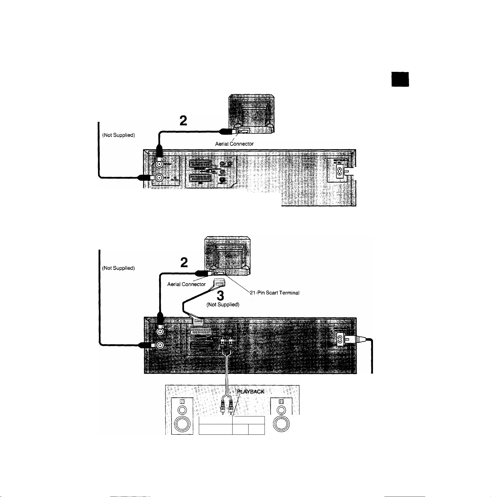
Connections
This tells you how to connect with an aerial, TV, etc.
Basic Connections
The following connections are required to record anc
back the VTR through TV set:
Aerial
1
'v'V- ■'•'’"''■•.I.- ■■■
Precautions
■ Connections
IE*I 3
To mains supply
è
C3)
.c
CD
CO
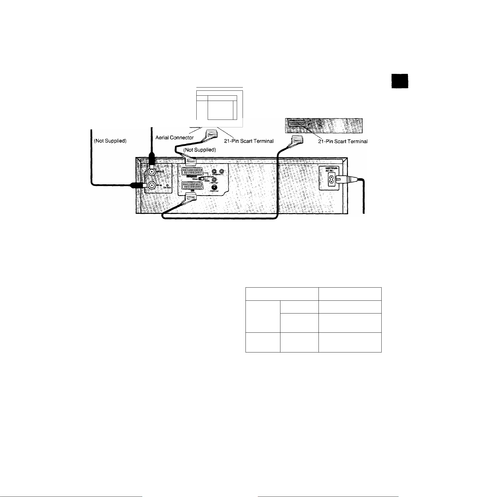
Connection to a TV Set with 21 -Pin Scart Terminal
TV Set (Not Supplied)
Aerial
1
To mains supply
□ZE3
§i
(Not Supplied)
•Connection to a Stereo Amplifier
‘. I o
nzi
bJ.id
CZD
Stereo Amplifier
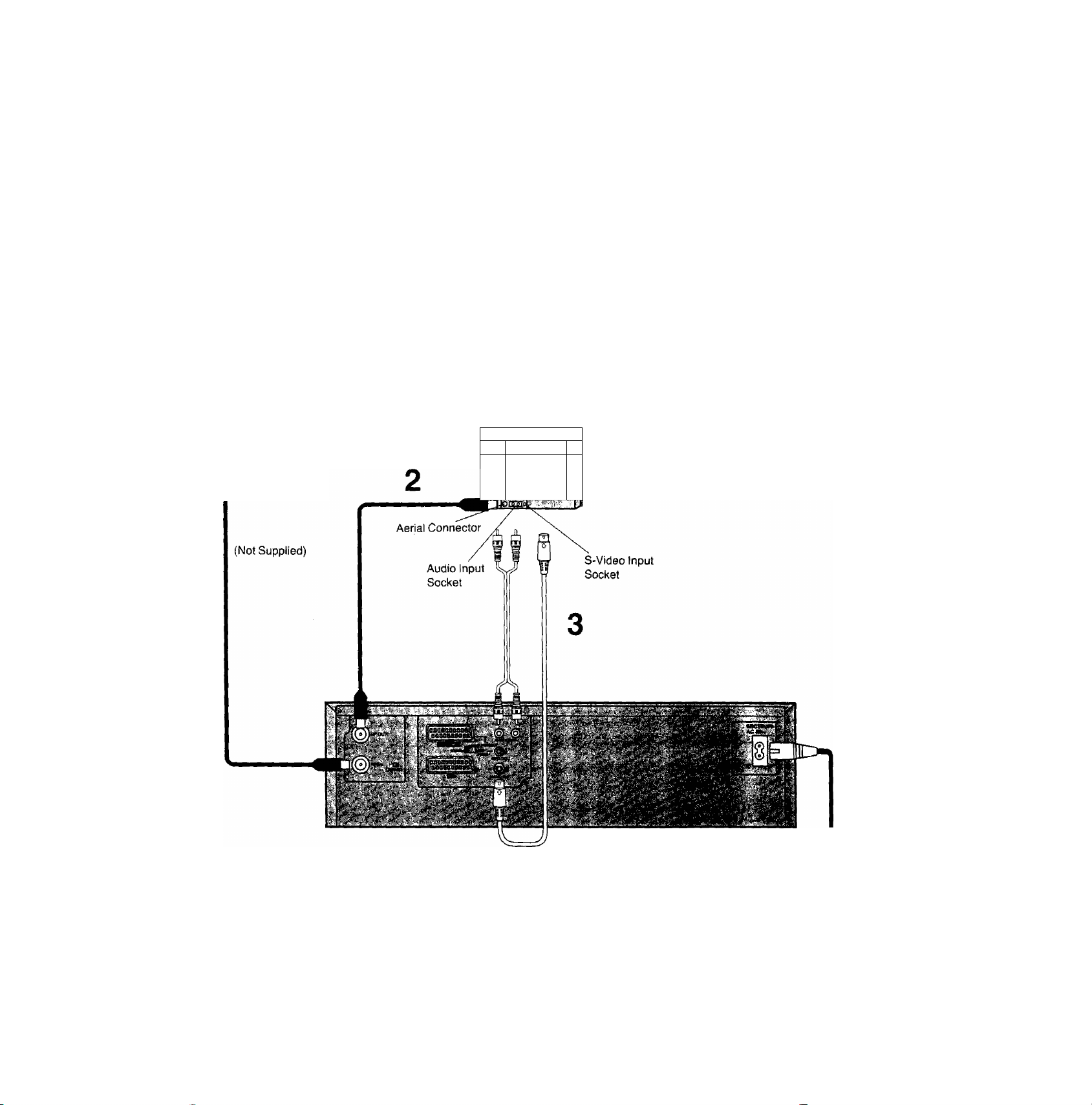
Connection to a TV Set with S-Video Socket
This VTR uses the S-VHS format that makes it possible to
obtain high resolution and high picture quality by using the
high-performance S-VHS video cassette tapes.
The conventional video sockets of VTRs output (input) a
combination of the luminance signal (Y) and colour signal
(C) which are recorded on the video tape. The new S
(Separate)-Video Socket allows separate transmission of
signals in order to obtain clearer pictures.
The connection with the S-Video Cable can also be used for
playback of a tape that was recorded in the conventional
VHS system. The “S" in the “S-Video Socket" stands for
“SEPARATED Y/C" not for “S-VHS".
TV-Set (Not Supplied)
li'
Vi-'
Aerial
J
k
1
To mains supply
Connection to a Decoder
Aerial
TV Set (Not Supplied)
у '■
i»'-
Щ
ll
L
t-”
Щ
if
<
I
Decoder (Not Supplied)
Connections
%
О)
.С
■is
■w
ф
со
(Not Supplied)
Note:
If the TV set is provided with an RGB-compatible connector,
connect the 21 -pin AV cable from the VTR to this
connector. Use full-pin 21 -pin AV cables for connecting the
TV set and VTR and for connecting the VTR and decoder.
AV LINK
With this button the connected colour TV set can be
switched from TV mode to VTR mode (vice versa) when it is
connected by means of 21 -pin scart cable.
This makes a variety of functions possible, such as
simultaneous recording and viewing when a Pay TV (e.g.
Canal Plus, Filmnet) decoder or a satellite receiver has
been connected.
VTR mode (VTR indicator lights):
To enjoy sound and pictures from the VTR.
TV mode (VTR indicator goes off):
To watch another programme on the TV while recording on
the VTR.
•Select the programme to be watched using the TV set’s
tuner.
•The sound and pictures of a different channel are received
by the VTR.
To mains supply
■ ^ VTR-.' TV set
VTR mode AV input selected
Power Om
TV mode
Power Qft
‘When the VTR is set to the TV mode and the Pay TV
channel is selected, the signals will still be scrambled even
when Pay TV is selected by the TV set's tuner, At a time
like this, either set the VTR to the VTR mode or switch the
TV set's input signals to AV input.
Input from TV set’s
tuner*
Input from TV set’s
tuner
Tuning the TV to your VTR
un
1,3
Operations
1
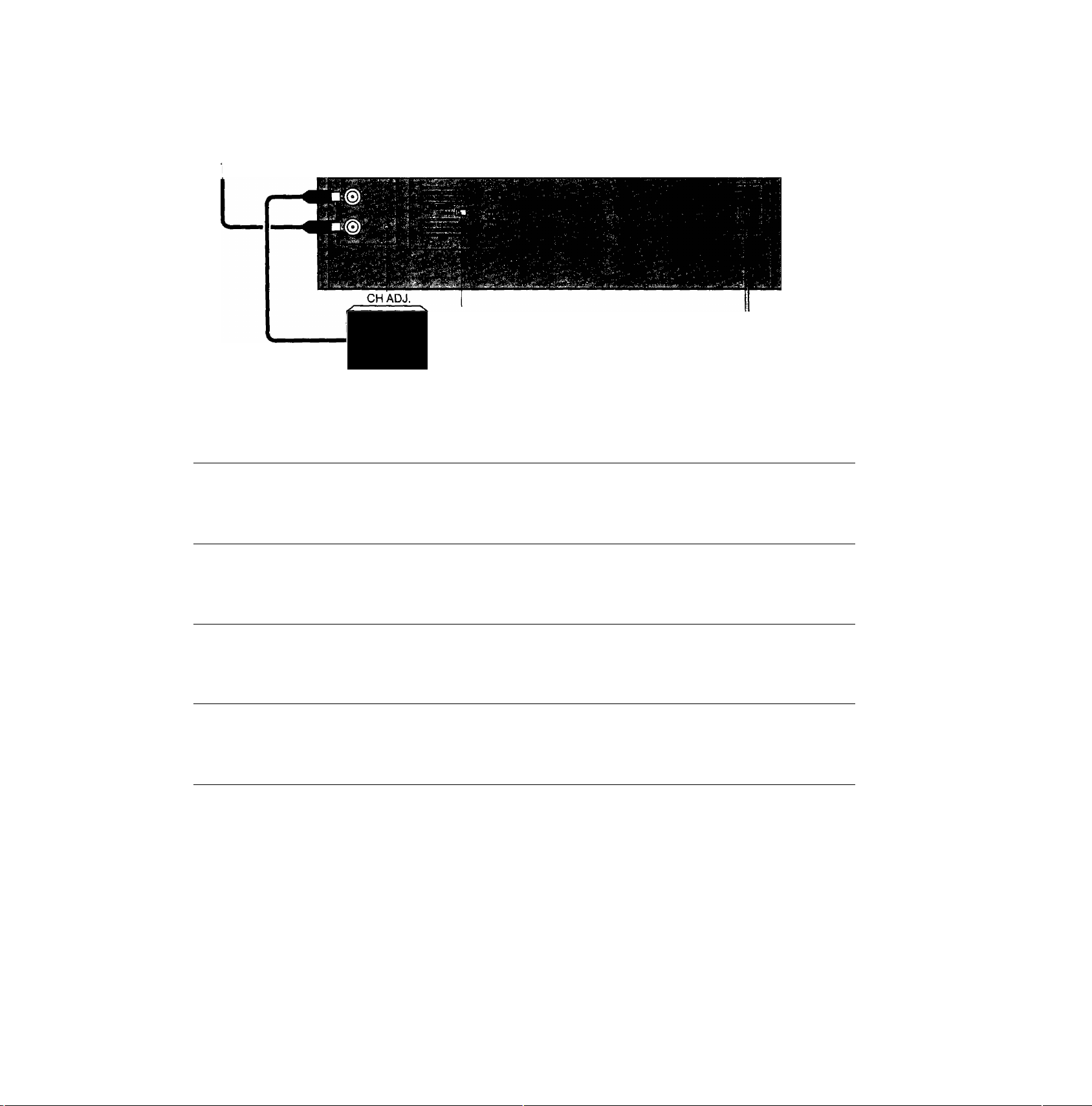
The VTR supplies a signal to the TV set via the RF coaxial
cable on channel 36.
It is possible to view the video picture on your TV in the
same way that you watch TV broadcasts.
If you have connected the VTR to the TV through the 21 -pin
scart terminal or Audio/Video/S-Video output sockets then
you do not need to follow the procedure mentioned below.
1 OPERATE
CD
2
NORMAL^ □ jiTEST
«
----
S-VIDEOOUT
SIGNAL
3
Hi
4
NORMAL^ □ (iTEST
Note;
The test signal is transmitted on video channel 36. If you
are encountering interference from a TV broadcast on this
video channel, you may readjust to another free
channel (32'-40) by using the CH AOJ. screw which is
located on the rear of the VTR. When rotating the CH ADJ,
screw, take care not to turn it too far.
Please note that if the CH ADJ. screw is used then you will
have to retune your TV to the test signal as in item 2 to 4
above.
S-VlDEOOUT
SIGNAL
Turn on the TV and VTR.
To generate a test pattern, set NORMAL/
S-VIDEO OUT/TEST SIGNAL to TEST
SIGNAL
Set the TV to an unused position which you
wish to use for your video playback.
Set NORMAL/S-VIDEO OUT/TEST
SIGNAL to NORMAL
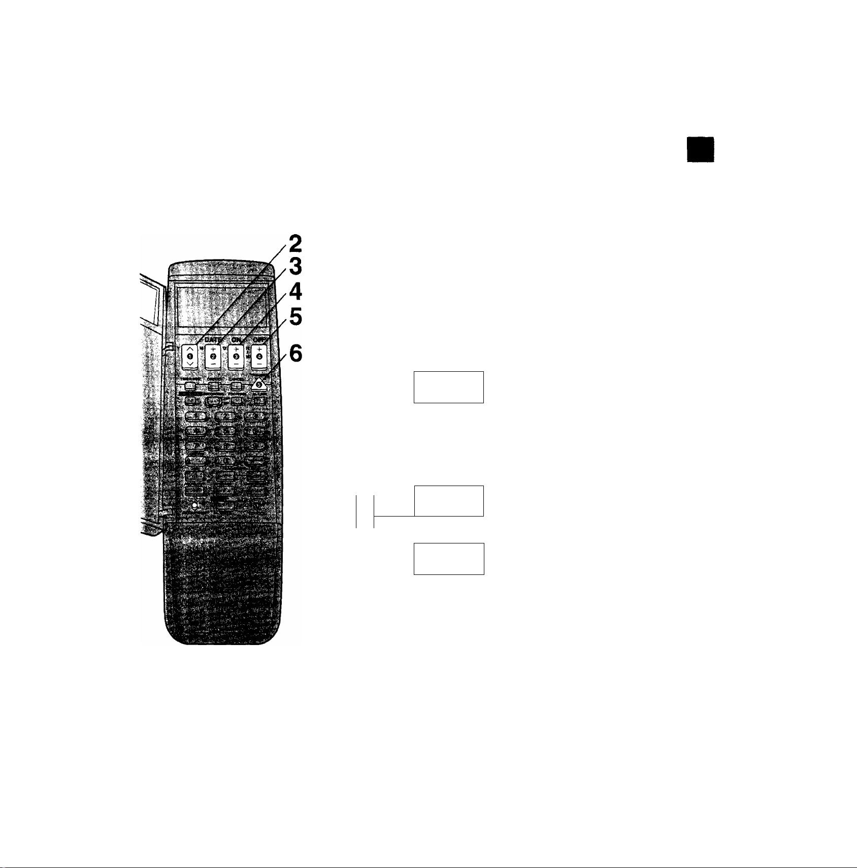
Setting the Clock of the VTR
By setting the time on the remote controller’s clock and then
by transmitting this setting to the VTR, the clocks on both
the remote controller and VTR display the same time.
The built-in digital clock employs the 24-hour system.
Operations Display Symbols
vm
1
vmi
mi
Tuning the TV to your VTR
Setting the Clock of the VTR
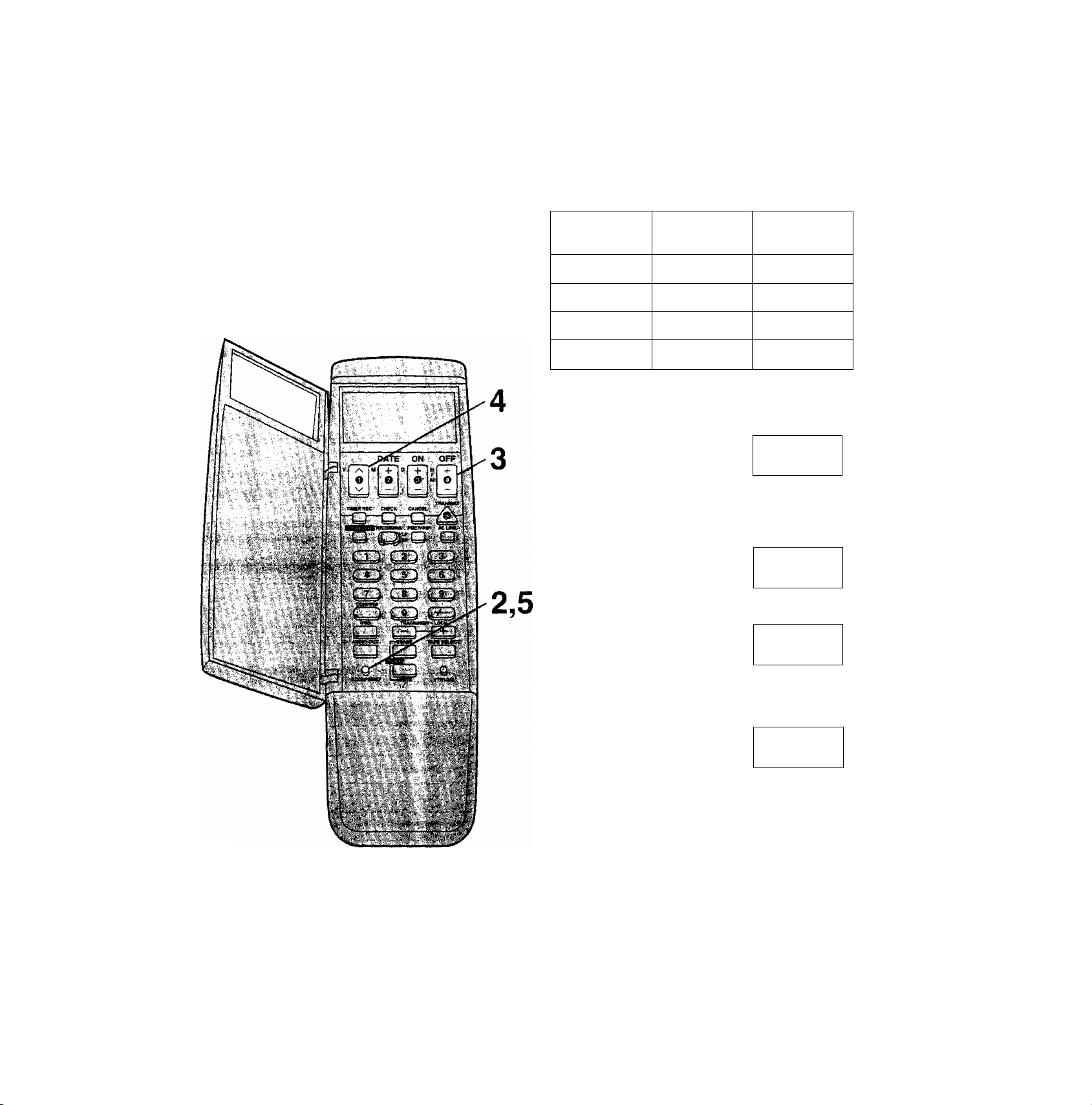
Preparation
•Turn on the VTR.
• Install the batteries in the remote controller. See page 17.
For Example:
Date; 16th, October, 1999
Time; 20:15
open the door of the remote
zn^rtn
- M 0
■zd
controller.
Set Year "99”.
r M 0
g.. -
è
•S
t:
<D
CO
DATE
M -f.
ON
OFF
+
Q
^ ^
TRANSMIT
Note:
To change the previous clock setting, press CLOCK/
PRESET for at least 2 seconds. The previous clock setting
will be displayed. Then follow steps 2 to 7 above.
VTR1 i
V ii'i o;.^ ; ■
‘Y
Si
r 10 -
VTR1
r U S
MJLA.
mi
«!!!£&■ ¡5
mi
f »; f
aft »n fC J
yy tu la g
mi. T—TT-"
' ■ ^ s*
u
iC.
Set Month “10”.
Set Date “16”.
Set Time "20:15”.
•When it is kept pressed, the
indication changes in 30-minute
steps.
Press TRANSMIT.
Close the door of the remote
controller.
1,3 2
In addition to setting the VTR clock from the remote
controller, it can also be set directly from the VTR,
The built-in clock is used to activate the timer for automatic
recording and must be set to the correct time.
The built-in digital clock employs the 24-hour system.
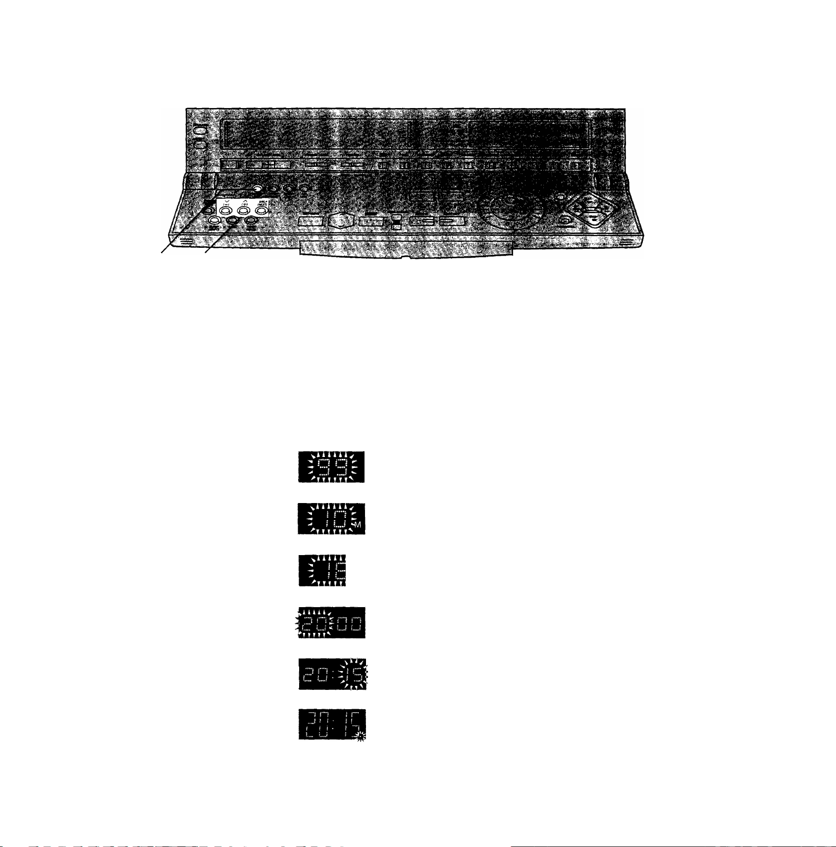
Operations Display Symbols
Preparation
Turn on the VTR.
For Example:
Date; 16th, October, 1999
Time; 20:15
1
2 Set each item by pressing (+) or \/ (-) and SP/LP (NEXT).
o
CLOCK
SET
o o
SP/LP
(NEXT)
O
Keep CLOCK SET pressed for more than
2 seconds.
Set Year "99”.
Set Month “10”.
Set Date “16”.
Set Hour "20”.
Set Minute "15”.
•There is no need to press SP/LP (NEXT).
o
CLOCK
SET
Note:
The clock operates for at least 60 minutes by its backup
system in the event of power failure.
Press CLOCK SET.
•The clock will start.

Time Reset Function
If the clock is less than two minutes slow or fast, it can
easily be reset to the proper time.
For example;
Resetting the clock to 12:00.00
1 Keep CLOCK SET pressed at any time between
11:58.00 and 12:01.59 for more than 2 seconds.
2 Press CLOCK SET again as soon as you hear the
12:00.00 time signal.
Setting the Clock of the VTR
§
O)
.c
6
CD
CO
Summer Time Function
Setting to summer time
1 Keep CLOCK SET pressed for more than 2 seconds.
2 Press SLEEP (SHIFT).
•The time on the clock is advanced by 1 hour.
3 Press CLOCK SET. Returning from summer time to standard time
1 Keep CLOCK SET pressed for more than 2 seconds.
2 Press SLEEP (SHIFT) twice.
•The time on the clock is set back by 1 hour.
3 Press CLOCK SET.
11
storing TV Broadcasts into your VTR
Cu* . "IT- ^ ... ■ :■.
m
.iV'
1,5 3 2,4
Introduction
The VTR is fitted with its own tuner (just like a normal TV
set) and can be pre-set to receive up to 99 TV broadcast
stations.
Operations
Display Symbols
1
o
TUNER
PRESET
{-) {+) (MEXT)
o
SLEEP
(SH[FT)
SP/LP
00-0
Preparation
•Confirm that the TV is on and the VTR viewing channel is
selected.
•Turn on the VTR and Select the programme position
except A1, A2 and A3.
Keep TUNER PRESET pressed for more
than 2 seconds.
Select the programme position, then press
SP/LP (NEXT).
Select normal TV station or Pay TV (e.g.
Canal Plus, Filmnet) station.
• 1; To preset normal TV stations.
•2: To preset Pay TV stations.
\/
(-) (+)
oo
o
TUNER
PRESET
Search for the required TV station.
•Press SP/LP (NEXT) and repeat steps 2-4 for each
programme position you want to tune to a station.
Press TUNER PRESET twice.

Storing TV Broadcasts into your VTR
§
O)
.C
00
Direct Channel Input Tuning Procedure
If you know the channels on which the TV stations can be
received, the TV stations can be tuned in by following the
steps given below,
1 Keep TUNER PRESET pressed for more than
2 seconds.
2 Select the programme position by using A (+) or V
(-), then press SP/LP (NEXT).
3 Select normal TV station or Pay TV (e.g. Canal Plus,
Filmnet) station by pressing SLEEP (SHIFT).
• 1; To preset normal TV stations.
•2: To preset Pay TV stations.
4 Input the channel number for the required TV station by
using Number buttons on the remote controller.
•Press SP/LP (NEXT) and repeat steps 2-4 for each
programme position you want to tune to a station.
5 Press TUNER PRESET twice.
Fine Tuning Procedure
1 Keep TUNER PRESET pressed for more than
2 seconds, and then press again.
2 Press SP/LP (NEXT).
3 Press A (+) or V (—) to obtain the best tuning
condition.
•"AFC” Indicator disappears.
•To return the tuning to its former state, press SLEEP
(SHIFT).
4 Press TUNER PRESET.
Blanking of Unoccupied Programme Positions
1 Keep TUNER PRESET pressed for more than
2 seconds.
2 Select a programme position which you do not want to
tune to a TV station, by using A (+) or V (-).
3 Press SLEEP (SHIFT). ” is displayed.)
•Repeat steps 2 and 3 for another unoccupied
programme positions to skip during the selection of the
programme positions.
•To cancel the blanking of a programme position, select
that programme position on the VTR and then press
SLEEP (SHIFT).
4 Press TUNER PRESET twice.
Channel Plan
'y '
Chamiel truScatlofi^i,
,4- *v-
2-12
13-20
21-69
74-76
80-82
83-89
hiJ'-' i . ''
E2-E12
—
21-69
SI-S3
M1-M3
M4-M10
90-99
121-141
U1-U10
S21-S41
13
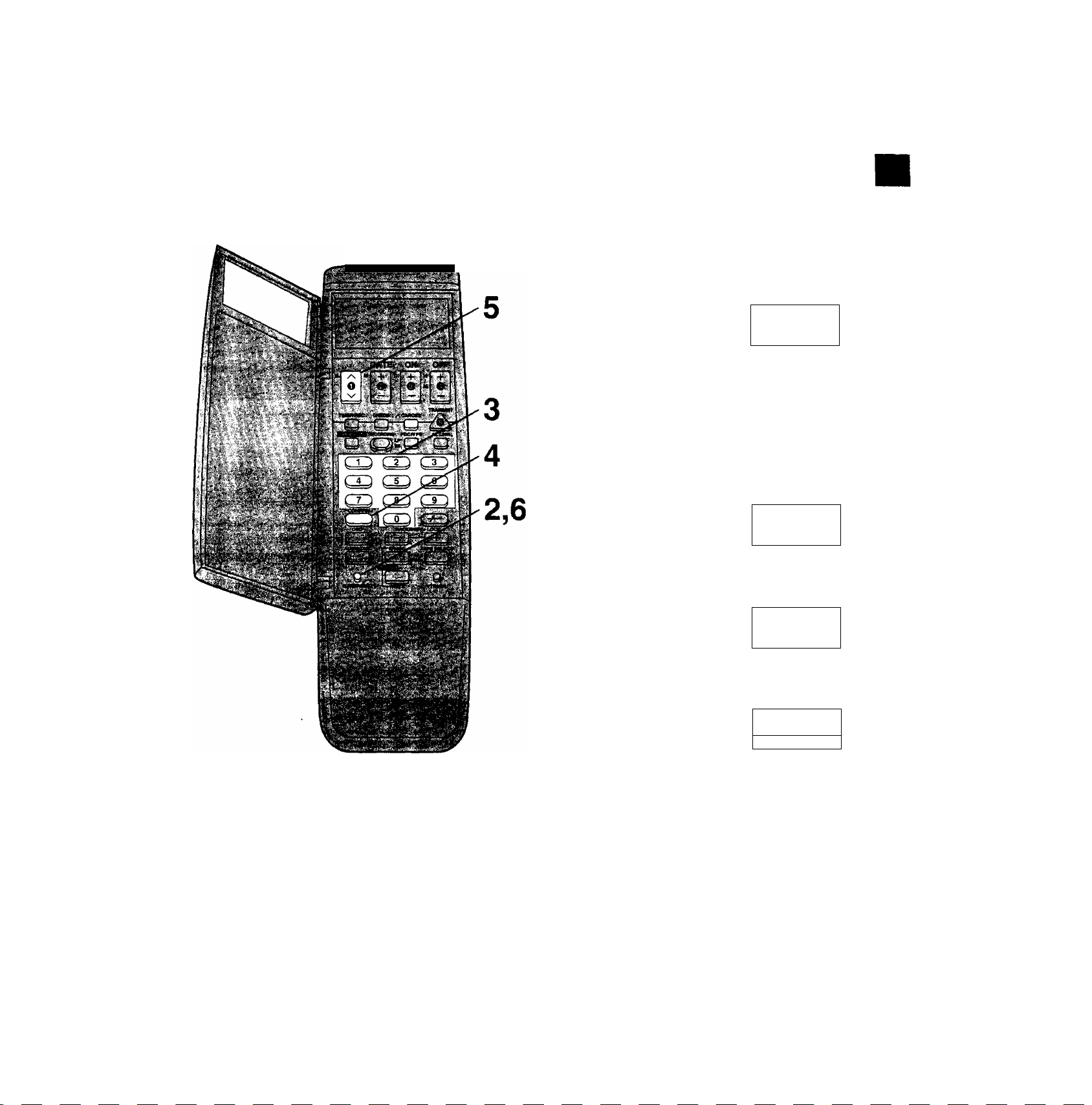
Setting Up the Remote
Controller for the ShowView
Programming
This remote controller uses specially designated numbers
called “guide numbers’’ to differentiate between the TV
stations. Before programming using the ShowView
numbers, you must enter the guide numbers of the TV
stations to be viewed and the programme positions at which
those TV stations are received on the VTR into the remote
controller. Have a newspaper or magazine at hand which
lists the TV station guide numbers and ShowView numbers.
Preparation
Set the clock of the remote controller first.
For Example:
TV Statl<m*;
ARD 001
ZDF
RTL
; Gukkr Number
002
004
progranmte
Poeitloir
1
2
4
SAT1
Operations
005
Display Symbols
Open the door of the remote controller.
VTR1
(tews
D ON
Keep CLOCK/PRESET pressed for
more than 2 seconds and then press it
again.
o
CLOCK/PRESET
mr.
Select the guide number (001-255).
3
OFF
+
VTB1
o
A Select the programme position
^ (1-99, At-A3).
3
OFF
■ n n 1
KimLi
UU t
n n 1
u u»
Note:
To receive satellite stations, the satellite receiver must be
connected to the VTR and programme position must be set
depending on the type of the connection made.
A1: When the satellite receiver is connected to the AV1
socket
A2: When the satellite receiver is connected to the AV2
socket
A3; When the satellite receiver is connected to the
Audio/Video input sockets (AV3)
•When the satellite receiver is connected by means of the
RF coaxiai cable, set to a free programme position
between 1 and 99,
■r
•To set the other TV stations, repeat steps 3 and 4.
. 0 n 1
uu 1
Press CLOCK/PRESET twice.
O
CLOCK/PRESET
¡a«® c» tiff ■
Close the door of the remote controller.
Storing TV Broadcasts into your VTR
O)
.c
S
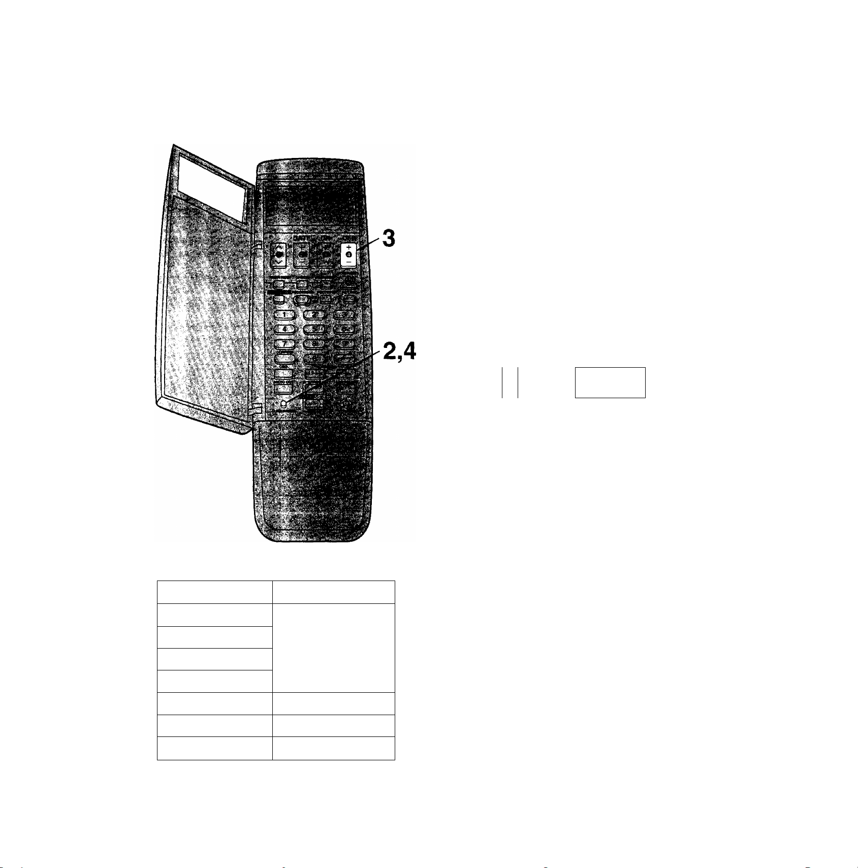
If you do not know the Guide Number of a
TV Station
You can set it by figuring it out from the ShowView number
for the programme broadcast by that station.
Operations
Display Symbols
Open the door of the remote controller.
VTHl ■
■■ ,
w« o-'.sit- ■■ ■ ■. ■ 0№’'
Keep CLOCK/PRESET pressed for
more than 2 seconds and then press it
again.
mi
o
CLOCK/PRESET
Enter a ShowView number.
3
Example: 744286
•If you have entered the wrong number, press
CANCEL and then enter the proper number.
Press CONFIRM to set the guide
number.
CONFIRM
o
vTfii
--
esoio
n n t
u u <
Vtnr
uuo
CO
Select the programme position
(1-99, A1-A3),
h nr
5 "
•To set the other TV stations, repeat steps 3 to 5.
Press CLOCK/PRESET twice.
mi »/-
CLOCK/PRESET
Q
Close the door of the remote controller.
Note:
Enter ShowView numbers which are ahead of the present
time. Otherwise, they will not be set into the proper guide
numbers.
’KW D:'4 w
u uo
QFF
15
Setting the Remote Controller for Operation of
your TV
You can operate some manufacture of TVs (see table
below) using the supplied remote controller after this setting
up.
Preparation
•Turn on the TV.
•Install the batteries in the remote controller.
Operations
Display Symbols
^ Open the door of the remote controller.
O Keep CLOCK/PRESET pressed for
^ more than 2 seconds and then press it
twice.
o
CLOCK/PRESET
•“TV” now appears on the remote controller's
display.
Press OFF several times.
OFF
o n
J
•When the number matches the manufacturer of
your TV, the TV’s power is turned off.
. J
Number
1
2
3
4
5
6
Panasonic
GRUNDIG/Blaupunkt
PHILIPS
Press CLOCK/PRESET.
o
CLOCK/PRESET
iwn ■"¿ff;
Close the door of the remote controller.
When the number is 1,2,3 or 4;
When the TV’s power is turned off in step 3 above, turn it
back on and adjust the TV’s volume using this remote
controller. The volume can be adjusted if the number
matches the manufacturer of TV. if it is not possible to
adjust the TV’s volume, try setting the number (1 to 4) to
match the manufacturer of TV again until the volume can be
adjusted.
Note:
Some TV models cannot be operated using this remote
controller.
16
7
SONY
Power Source for the Remote
Controller
The remote controller is powered by 2 “UM3" or "R6” size
batteries. The life of the batteries is about one year,
although this depends on the frequency of use.
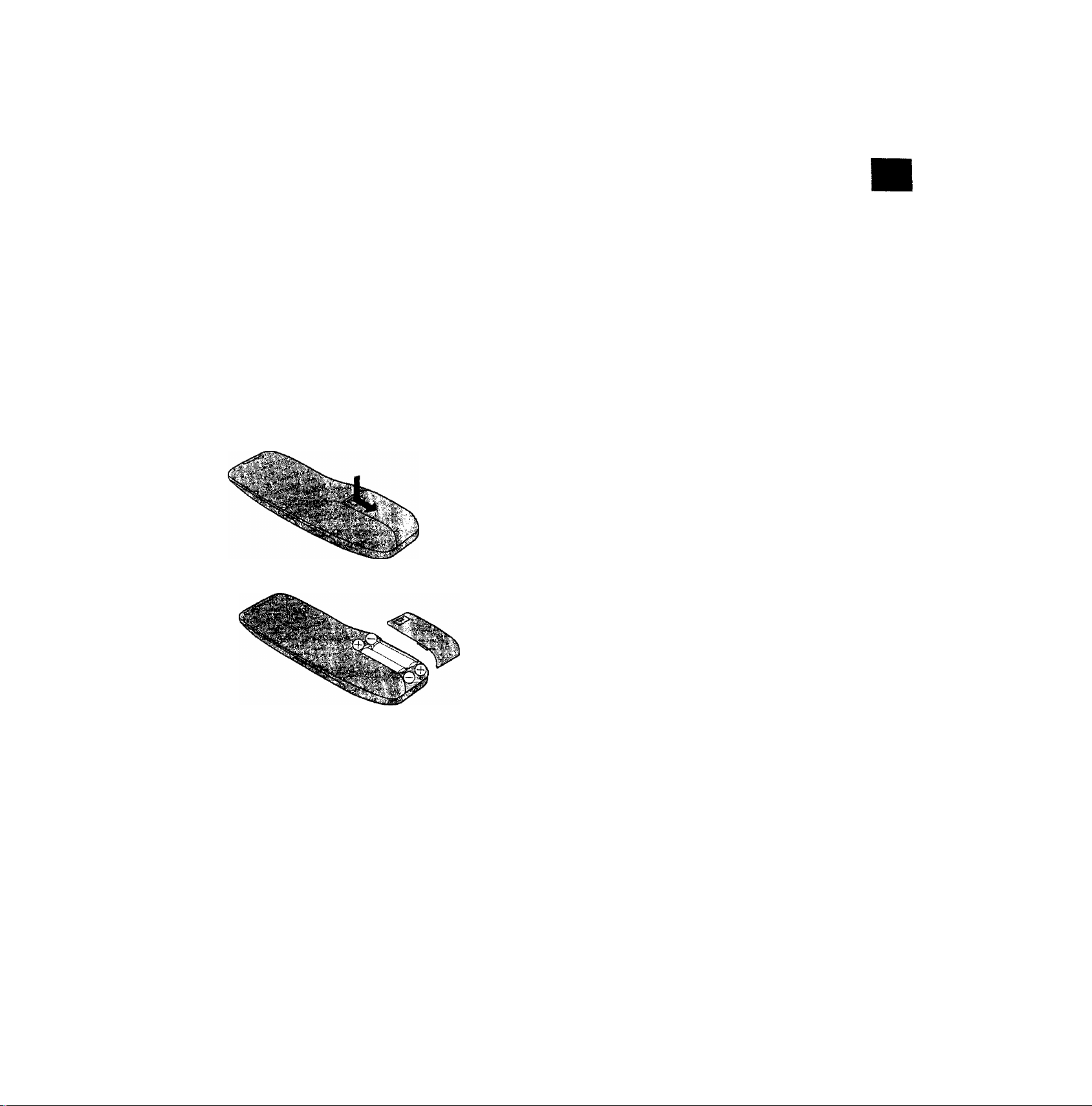
Precautions for Battery Replacement
•Load the new batteries with their polarity (© and ©)
aligned correctly.
• Do not apply heat to the batteries, or an internal
short-circuit may occur.
• If you do not intend to use the remote controller for a long
period of time, remove the batteries and store them in a
cool and dry place.
• Remove spent batteries immediately and dispose of them.
•Do not use an old and a new battery together, and never
use an alkaline battery with a manganese battery.
Installing the Batteries
Setting the Remote Controller for Operation of your TV
§
O)
.c:
CD
CO
17
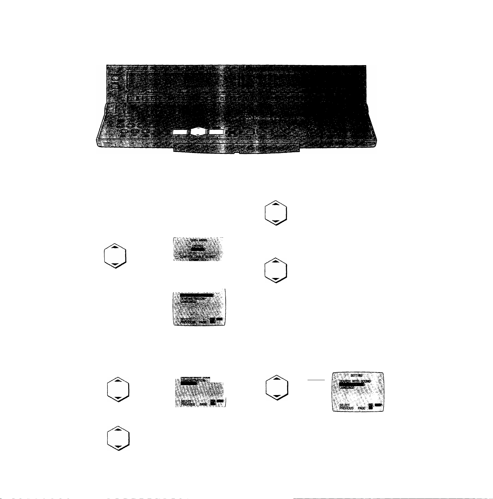
Initial Settings Using On Screen Displays
Preparation
•Confirm that the TV is on and the VTR viewing channel is
selected.
•Turn on the VTR.
1 Press EDIT MENU.
2 Select SETTING.
3 Press ENTER.
On Screen Display
S^S-SEtSCr :|
To select the Desired Language
Select one of the seven languages displayed: English,
German, French, Italian, Spanish, Dutch and Swedish.
Follow steps 1 to 3 of the above procedure.
4 Select LANGUAGE.
To select Sound Setting
Follow steps 1 to 3 of the above procedure.
4 Select SEARCH WITH SOUND.
SEmtIG
:SBiET 'Bi
FflWlOUS. PAGE ;«
5 Select the desired setting.
vwm sower"
■■i №
J
||,l
u.
AUTO: The sound can be heard during special playback
only when an editing operation is in progress.
ON: The sound can be always heard during special
playback.
OFF: The sound can not be heard during special
playback.
To View a Demonstration
Follow steps 1 to 3 of the above procedure.
4 Select DEMONSTRATION.
PAGT-.
5 Select the desired language.
J
S№HSt(ft
^ecT'
PRtinOOS PASe
lAMIlSl
►The On Screen Displays for editing are displayed one
after the other at about five second intervals.
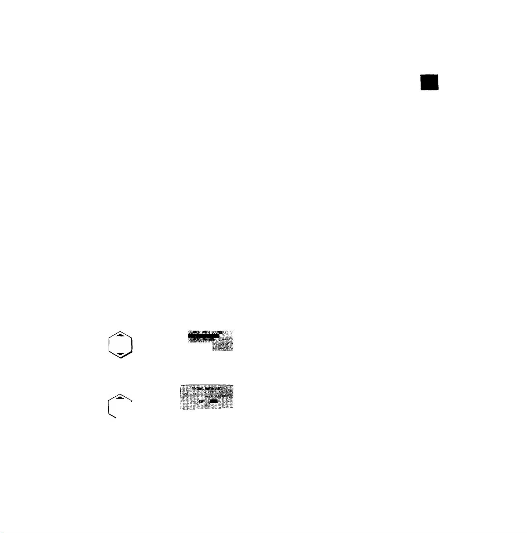
Optional Function
VITC (Vertical Interval Time Code) Function
As an address (individual number) is recorded for each
frame, it is possible to find the accurate position of any
desired scene or picture on a tape by checking the address
during playback. This address is called “Time Code”.
Since the VITC signals (Vertical Interval Time Code) are
recorded together with the picture signals, they will not be
cancelled even when the video cassette is taken out from
the VTR or the VTR is switched off. This makes it possible
to check the precise position of any desired picture at any
time.
•The VITC function becomes operative when the VTR is
equipped with the optional VITC adaptor. Consult your
authorized video dealer.
Follow steps 1 to 3 of the above procedure.
4 Select EDITING WITH VITC.
5 Select the desired setting.
fis'
J'^ED
iupwgrous ‘ Pm ;]■? 7
ON;
For reading the VITC signals during playback and
writing them during recording.
The time code is indicated on the counter in
increments of hours, minutes and seconds. During
programme editing, it appears on the screen in
increments of hours, minutes, seconds and
frames (25 frames per second).
OFF:
The normal counter is displayed.
Initial Settings Using On Screen Displays
Reading the VITC signals
—,—” appears on the counter when the cassette is
inserted. When playback is started, the VITC signals are
read and the time code is displayed.
•When VITC signals have not been written on the tape, the
time code is not displayed.
Writing the VITC signals
—.—” appears on the counter when the cassette is
inserted. When recording is started, the VITC signals are
written starting at OhOOmOOsOOf.
If recording is started after the tape has been played back
and the VITC signals read, the VITC signals will be written
following on from the time code which is displayed on the
counter at that time.
Notes:
•To use the VITC function to edit, be sure to first turn on the
VITC function with the procedure described above, then
begin editing after cancelling all editing programmes used
last time.
•When tracking is out of adjustment, the VITC signals may
not be properly read,
•The counter cannot be reset when the VITC function is on.
This is because the VITC signals are recorded on the
tape.
•When the VITC function is on, up to 50 scenes can be
programmed in the programme assemble editing mode.
If the VTR is not equipped with the optional VITC adaptor,
a maximum of 10 scenes can be programmed using the
counter.
•To make optimal use of the advantages offered by the
VITC function during editing, this VTR should be
connected to another NV-HS1000 also equipped with the
VITC function.
When this VTR is to be connected to another unit which is
not equipped with the VITC function, the editing precision
will be increased if the NV-HS1000 is used as the
playback VTR.
è
D)
.C
•«w
CÙ
CO
19
 Loading...