

Page 1
J
Disrating rifstructions
Video Cassette Recorder
NV-HD70EA
jr-COOE
QT5597 ,
J i ■-■«•'SU-'
■1 ^
-1
*
VI4S suPBi^iive
PAL SYSTtM
Before attempting to connect, operate or adjust this product,
please read these instructions completely.
Page 2
Dear Customer
May we take this opportunity to thank you for purchasing this
Panasonic Video Cassette Recorder,
We would particularly advise that you carefully study the
Operating Instructions before attempting to operate the unit and
that you note the listed precautions.
G-Code Programming System
Programming is now easier than ever; simply enter the
G-Code number provided in the programme schedule
column carried by newspapers and magazines,
• G-Code is a trademark applied for by Gemstar
Development Corp, G-Code system is manufactured
under licence from Gemstar Development Corporation,
AI Crystal View Control
Al circuit for automatic tape calibration (computer-
controlled calibration) and optimizing of playback
characteristics.
During playback the contrast of tapes recorded with good
level is automatically optimized; when a tape recorded with
insufficient level is played back, the noise reduction circuit is
activated automatically.
Page 3

Information for Your Safety
Contents
Setting Up
IMPORTANT
Your attention is drawn to the fact that
recording of pre-recorded tapes or discs
or other published or broadcast material
may infringe copyright laws.
WARNING
TO REDUCE THE RISK OF FiRE OR
SHOCK HAZARD, DO NOT EXPOSE
THIS EQUIPMENT TO RAIN OR
MOISTURE.
FOR YOUR SAFETY
■ DO NOT REMOVE OUTER COVER.
To prevent electric shock, do not remove
cover. No user serviceable parts inside. Refer
servicing to qualified service personnei.
HQ (High Quality) Picture System
Video recorders carrying the HQ symbol mark feature the
new VHS High Quality Picture System. This system
assures complete compatibility with VTRs that use the
conventional VHS system.
Connections.................................................................. 4
Tuning the TV to your VTR
Setting the Clock of the VTR
Storing TV Broadcasts into your VTR
Preparations for G-Code Programming
Setting the Remote Controller for Operation of
your TV....................................................................... 12
Playback
On-the-spot Recording
........................
.......................................
.......................................
........................
....................
5
Advanced Opeiations
Timer Recording......................................................... 18
•Using the Remote Controller....................................... 20
•G-Code Programming
Other Functions.......................................................... 22
Editing
•Assembly Editing......................................................... 23
........................................................................
...............................................
21
23
6
3
10
14
16
Descripfion
Controls and Connection Sockets
Infra-red Remote Controller ..........
Heipfiil Hints
Before Requesting Service........................................ 28
Precautions................................................................. 30
Specifications............................................................. 31
24
26
Page 4
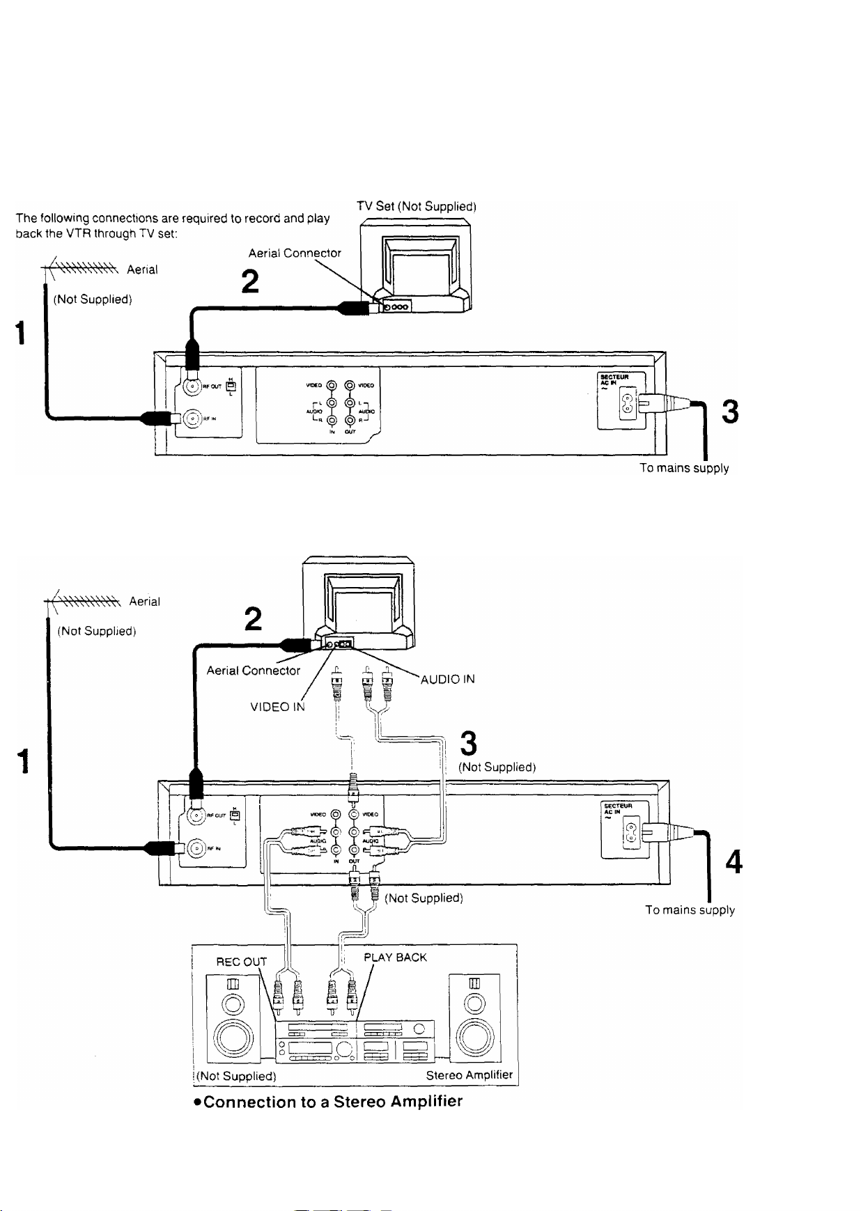
Connections
This tells you how to connect with an aerial, TV, etc.
Basic Connections
Connection to a TV Set with Audio/Video Input Sockets
TV Set (Not Supplied)
Page 5
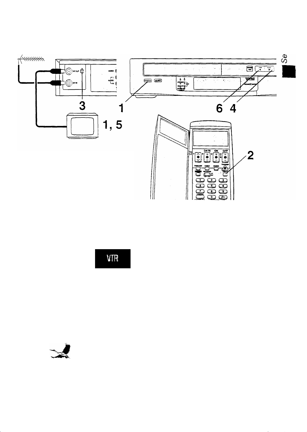
Tuning the TV to your VTR
The VTR supplies a signal to the TV set via the RF coaxial
cable on channel 2 or 3.
It IS possible to view the video picture on your TV in the
same way that you watch TV broadcasts.
If you have connected the VTR to the TV through the
video and audio input sockets then you do not need to
follow the procedure mentioned below. Instead, simply
select AV mode on the television.
Connections
Tuning the TV to your VTR
è
O)
c
Operations
1
POWERO/I
vTRm/
o
H
PLAY
Display Symbols
Turn on the TV and VTR.
Select the VTR mode.
Select the video playback channel which is
not occupied with any TV station.
H: Channel 3
L: Channel 2
Insert a recorded cassette tape and press
PLAY.
Select a programme number on the TV set
which you wish to use as the video viewing
channel. Then tune in the TV to the picture
from the cassette tape currently playing.
STOP
Stop the playback.
Page 6
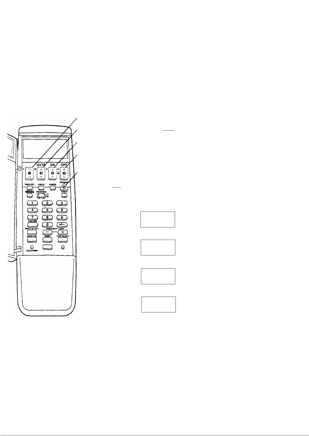
Setting the Clock of the VTR
By setting the time on the remote controller's clock and then
by transmitting this setting to the VTR, the clocks on both
the remote controller and VTR display the same time.
The built-in digital clock employs the 24-hour system.
Operations Display Symbols
2
1
3
4
5
6
DATE
+
Preparation
•Turn on the VTR.
• Install the batteries in the remote controller. See page 13.
For Example:
Date; 16th, October, 1999
Time; 20:15
vlil II
' n nn
Zu-uu
''I M I t
Open the door of the remote
controller.
Set Year “99’
V M D
00 - - -
Set Month “10’
Y M D
fH*' tn . _
ON
c( —
Note;
To change the previous clock setting, press CLOCK/
PRESET for at least 2 seconds. The previous clock setting
will be displayed. Then follow steps 2 to 7 above.
___
00
¡LlJiL.
00
D
Y
nil in
j,-
H D
ti't If
tu iCi ' ■
Y M
Y H D
0
iL' ?r
t\J LU
LL»'
m fi'
LU- tj
5A
■ 'd
i'A'i
SA
in- ir
Set Date “16”.
Set Time “20:15”.
•When it IS kept pressed, the
indication changes in 30-minute
steps.
Press TRANSMIT.
Close the door of the remote
controller.
Page 7
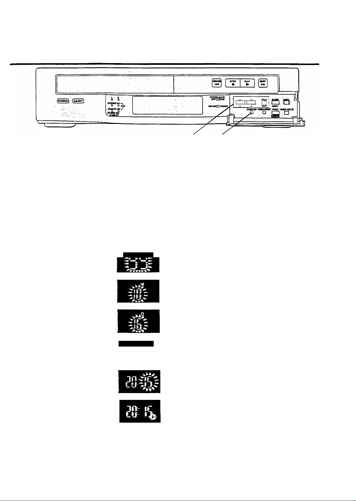
In addition to setting the VTR clock from the remote
controller, it can also be set directly from the VTR.
The built-in clock is used to activate the timer for automatic
recording and must be set to the correct time.
The built-in digital clock employs the 24-hour system.
Setting the Clock of the VTR
1,3
Preparation
Turn on the VTR.
For Example:
Date; 16th, October, 1999
Time; 20:15
§
O)
.C
Oi
CO
Operations
1
CLOCK SET
Display Symbols
О
2 Set each item by pressing + or — and NEXT.
I
Keep CLOCK SET pressed for more than
2 seconds.
Set Year “99”.
Set Month “10”.
Set Date “16”.
Set Hour “20”.
□
NEXT
CLOCK SET
О
Time Reset Function
If the clock is less than two minutes slow or fast, it can
easily be reset to the proper time.
For example:
Resetting the clock to 12:00.00
1 Keep CLOCK SET pressed at any time between
11:58,00 and 12:01.59 for more than 2 seconds.
Set Minute “15”.
•There is no need to press NEXT.
Press CLOCK SET.
•The clock will start.
2 Press CLOCK SET again as soon as you hear the
12:00.00 time signal.
Note:
The clock operates for at least 60 minutes by its backup
system ;n the event of power failure.
Page 8
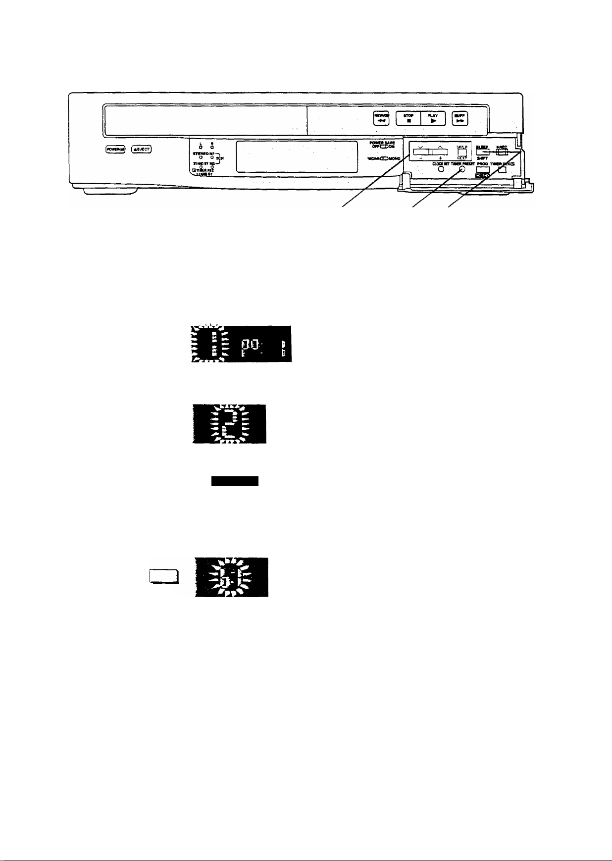
storing TV Broadcasts into your VTR
2-4 1,5 4
Introduction
The VTR IS fitted with its own tuner (just like a normal TV
set) and can be pre-set to receive up to 42 TV broadcast
stations.
Operations
1
TUNER PRESET
Display Symbols
o
] □
] □
NEXT
NEXT
Preparation
• Confirm that the TV is on and the VTR viewing channel is
selected.
•Turn on the VTR and select any programme position
except A1.
• Press VTR/TV to select the VTR mode.
Keep TUNER PRESET pressed for more
than 2 seconds.
Select the programme position, then press
NEXT.
Press + to select TV band “1”, “ill” or “U",
then press NEXT,
TUNER PRESET
O
SHIFT
Search for the required TV station by
pressing and holding + or -.
Release once the station has been found.
•Search speed changes quickly by pressing SHIFT
simultaneously with -i- or
•Press NEXT and repeat steps 2-4 for each programme
position you want to tune to a station.
Press TUNER PRESET twice.
Page 9

Fine Tuning Procedure
1 Keep TUNER PRESET pressed for more than
2 seconds, and then press again.
2 Press NEXT.
3 Press -f- or - to obtain the best tuning condition,
•“A” Indicator disappears.
•To return the tuning to its former state, press SHIFT.
4 Press TUNER PRESET,
Storing TV Broadcasts into your VTR
Cn
.c
■is
<D
CO
Blanking of Unoccupied Programme Positions
1 Keep TUNER PRESET pressed for more than
2 seconds.
2 Select a programme position which you do not want to
tune to a TV station, by using - or -.
3 Press SHIFT. (“—” is displayed.)
• Repeat steps 2 and 3 for another unoccupied
programme positions to skip during the selection of the
programme positions.
•To cancel the blanking of a programme position, select
that programme position on the VTR and then press
SHIFT,
4 Press TUNER PRESET twice.
Channel Plan
^ VHF
i 1-3
1
III U
4-11
UHF
21-69
Page 10
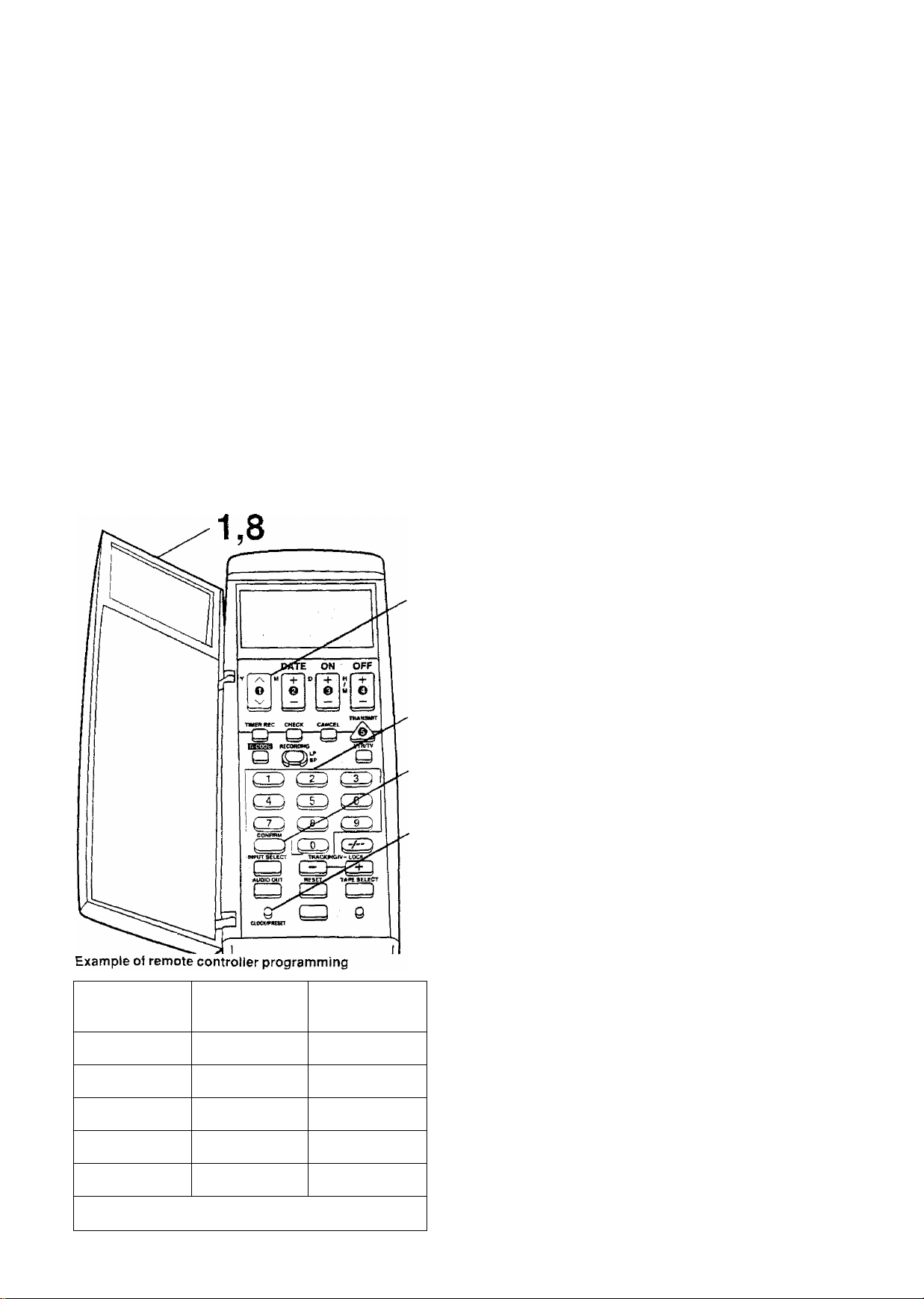
Preparations for G-Code Programming
Setting Up the Remote
Controller for the G-Code
Programming
Before using for the first time;
It IS necessary to programme your G-Code remote
controller with your local TV station G-Code identification
number and the programme position of your VTR at which
those stations are received. This should be done for each
TV station for which G-Coae programmes are listed. Have
a newspaper or magazine on hand which lists today 's local
TV station programmes and G-Code numbers.
Preparation
• Tune tne TV to your VTR See page 5.
• Set the Clock of the VTR. See page 6
• Store TV broadcasts into your VTR. See pages 8-9.
3
4
If you do not know the identification number of a TV
station for which a G-Code number is supplied, you
can determine the identification number by proceeding
as follows:
Operations
Display Symbols
Open the door of the remote controller.
1
Keep CLOCK/PRESET pressed for
more than 2 seconds and then press it
again.
o
CLOCK'-'PRESET
Enter a G-Code number listed in
newspaper against the first local TV
station in your area (say TV1).
• Enter the G-code number which is ahead of the
present time and date Otherwise the wrong
identification number will be generated.
• If you have entered the wrong number, press
CANCEL and then enter the proper number.
Press CONFIRM to set the identification
number.
U'J pc
( i 1L Ou
n n I
U L< I
! TV station
TV ONE
CHANNEL2
TVS
SKY TV MOVIES
SKY TV SPORTS
Programme
position on VTR
1
2
3
1
______________
i 1
1 ■ i ■
4
5
identification |
Number
001
002
003
_
1-
004
-------------------------------------------------------
005
2.7
1
Select the programme position of your
VTR which receives the TV station you
entered at step 3.
Select a G-Code number listed in
newspaper against the second local TV
station in your area (say TV2) and
repeat steps 3-5 until all G-Code
stations have been programmed into
the remote controller.
Press CLOCK/PRESET twice.
CLOCK PRESn
o
Close the door of the remote controller.
8
n n I
U U I
n n i
U Lt »
Page 11

Preparations forG~Code Programming
§
-C:
■*—
if you know the identification number of a TV station for
which a G-Code number is suppfied, you can set the TV
station by proceeding as follows:
4
3
2,5
Operations
Open the door of the remote controlier.
Display Symbols
1
2 Keep CLOCK/PRESET pressed for
^ more than 2 seconds and then press it
again.
o
CLOCK; PRESET
O Select the identification number
^ (001-255).
OFF ,
Select the programme position (1-42,
4
AD.
____________
ii n I
U IJ I
n i7 I
U IJ I
n n )
U U I
CO
•To set the other TV stations, repeat steps 3 and 4.
Press CLOCK/PRESET twice.
o
]LOCK,PRESET
Close the door of the remote controller.
Note;
To .''eceive sateilite stations, the satellite receiver must be
connecteo to the VTR ana programme position must be set
depenamg on the type of the connection made.
A1: When the satellite receiver is connected to the
Audio, Video input sockets
• When the sateilite receiver ;s connected oy means of the
RF coaxial cable, set to a free programme position
between 1 and 42.
Page 12

Setting the Remote Controller for Operation of
your TV
You can operate some manufacturer of TVs {see table
below) using the supplied remote controller after this
setting up.
2,4 3
Preparation
•Turn on the TV.
• Install the batteries in the remote controller. See page 13.
Operations
Display Symbols
^ Open the door of the remote controller.
Keep CLOCK/PRESET pressed for
more than 2 seconds and then press it
twice.
о
CLOCK'PRESET
•‘TV’’ now appears on the remote controller’s
display.
Press OFF several times.
OFF
Number
1
2
3
4
5 GRUNDIG.^Blaupunkt
6
Manufacturer
Panasonic
PHILIPS
•When the number matches the manufacturer of
your TV, the TV's power is turned off.
Press CLOCK/PRESET.
О
CL0GK''PRESE7
C ON OFf
Close the door of the remote controller.
How to change the number
Each time the side of OFF is pressed, the number is
counted up by one as follows:
r-1^2-.3...7
When the side is pressed, the number is counted down
by one in the reverse order to that indicated above.
Note;
Some TV models cannot be operated using this remote
controller.
When the number is 1,2, 3 or 4:
When the TV’s power is turned off in step 3 above, turn it
back on and adjust the TV's volume using this remote
controller. The volume can be adjusted if the number
matches the manufacturer of TV.
if it is not possible to adjust the TV’s volume, try setting the
number (1 to 4) to match the manufacturer of TV again until
the volume can be adjusted.
----------
,
¡2
7
SONY
Page 13

Power Source for the Remote Controller
The remote controller is powered by 2 “AA”, “UM3” or “R6”
size batteries. The life of the batteries is about one year,
although this depends on the frequency of use.
Precautions tor Battery Replacement
• Load the new batteries with their polarity
aligned correctly.
• Do not apply heat to the batteries, or an internal
short-circuit may occur.
• If you do not intend to use the remote controller for a long
period of time, remove the batteries and store them in a
cool and dry place.
• Remove spent batteries immediately and dispose of them.
• Do not use an oid and a new battery together, and never
use an alkaline battery with a manganese battery.
(0
and
0
)
Installing the Batteries
Setting the Remote Controller for Operation of your TV
Page 14

Playback
Operations Display Symbols
1
C i PAUSE.ST[LL
^ * *0
"'i \
Insert a recorded cassette
tape.
Start viewing the picture.
Search forward by tapping
FF.
•To change back to normal playback,
press PLAY.
Search backward by tapping
REW.
•To change back to normal playback,
press PLAY,
View a still picture.
• To continue the normal playback,
press PLAY or PAUSE/STILL
SLOW
View the slow motion
picture.
• To continue the normal playback,
press PLAY.
Stop viewing the picture.
Page 15

Playback
CO
C
.o
5
a
o
o
CO
cn
CX^
Other Playback Functions
To obtain High Speed Picture During Fast
Forward or Rewind
Keep FF pressed during fast forward.
Keep REW pressed during rewind.
To find the Beginning of Each Recording
For example:
Searching for the 2nd recorded segment in the forward
direction.
Press INDEX twice.
pINDEX—I
0 0
•After finding the specific recorded segment, playback
starts automatically.
•For the reverse direction, press INDEX .
• Up to 20 index signals can be searched for in both directions,
• The figure on the display is decremented by 1 each time
an index signal is located.
Notes:
•Audio reproduction of linear (conventionally recorded)
tapes will be monaural when played back on the FM Hi-Fi
video recorders.
• Cue, review or slow playback will be automatically
released after 10 minutes, and still playback after 5 minutes.
•The INDEX search funchon can only work correctly, if the
index signals are spaced at least 3 minutes apart in the
SP mode and 5 minutes apart in the LP mode.
Recording Index Signals
Index signals are recorded in following cases.
• When a recording is started by pressing REC
• When REC is pressed during recording
• When timer recording is activated
Page 16

On-the-spot Recording
1
5 3
Operations Display Symbols
1
I M I V
O
0
0
Insert a cassette tape.
• If it has already been inserted, press
POWER to turn the VTR on.
Select the VTR mode.
Select TV station.
4
3
0 O
K
r— REC —^
STOP
D
Start recording.
Stop recording.
Page 17

To select the Desired Tape Speed
1 Press RECORDING SP/LP to display the tape speed
indicator.
2 Keep RECORDING SP/LP pressed for more than
2 seconds while the tape speed indicator is displayed, to
change the tape speed.
£DING
/p
C3)s
On-the-spot Recording
CO
c:
.o
5
03
(§■
o
CO
cc
CQ
To interrupt Recording
Press PAUSE/STILL during recording.
Press again to continue recording.
PAUSE/STILL
0
To record One TV Programme while
Viewing Another Programme
1 Refer to the on-the-spot recording operations steps 1
to 4.
2 Press VTR/TV to select the TV mode.
3 Select the TV programme on your TV set you wish to
view at the present time.
To display the Approximate Remaining
Tape Time
1 Press TAPE SELECT to select the corresponding
cassette tape length.
TAPE SELECT
Q
E195: For E30, -60, -80. -120, -180 and -195 tapes
E240: For E240 tape
E260: For E260 tape
2 Press DISPLAY
DISPLAY
o
Clock —Counter -Remaining Tape Time
--------
Notes;
• When a video cassette with a broken off tab :s inserted,
the "EEI" indication will flash to indicate that recording is
not possible,
• The recording pause mode will be automatically released
after 5 minutes, and be back to the stop mode.
-
Page 18

On-the-spot Recording
1
5 3
Operations Display Symbols
1
/CIlZ^E)'
'/TRTV
o
3 0
0
Insert a cassette tape.
• If it has already been inserted, press
POWER to turn the VTR on.
Select the VTR mode.
Select TV station.
' r— REC —^
0 O
STOP
□
Start recording.
Stop recording.
Page 19

On-the-spot Recording
CO
C
o
CT3
CD
a
o
.o
To select the Desired Tape Speed
1 Press RECORDING SP/LP to display the tape speed
indicator.
2 Keep RECORDING SP/LP pressed for more than
2 seconds while the tape speed indicator is displayed, to
change the tape speed.
.RECORDING
To interrupt Recording
Press PAUSE/STILL during recording.
Press again to continue recording.
PAUSE/STILL
0
To record One TV Programme while
Viewing Another Programme
1 Refer to the on-the-spot recording operations steps 1
to 4.
2 Press VTR/TV to select the TV mode.
3 Select the TV programme on your TV set you wish to
view at the present time.
CD
OQ
To display the Approximate Remaining
Tape Time
1 Press TAPE SELECT to select the corresponding
cassette tape length.
TAPE SELECT
E195'. For E30, -60, -80, -120, -180 and -195 tapes
E240; For E240 tape
E260: For E260 tape
2 Press DISPLAY.
DISPLAY
O
Clock —Counter -Remaining Tape Time-
Notes:
•When a video cassette with a broken off tab is inserted,
the “EST indication will flash to indicate that recording is
not possible.
• The recording pause mode will be automatically released
after 5 minutes, and be back to the stop mode.
Page 20

Timer Recording
up to 8 timer programmes can be recorded up to one month
in advance by setting the timer.
Preparation
Insert a cassette tape with an intact erasure prevention tab.
Operations Display Symbols
For Example:
Timer Programme number; 1
Programme position (channel); 2
Date; 27th, October
Starting time; 20;02
Ending time; 21:30
(Present date; 16th October)
1
PROG
-CHECK, NEXT
2 Set each items by pressing + or - and NEXT.
□
KS
i
Select Timer Programme number “1 and
then press NEXT.
PI-------------------; When nothing is programmed
PI : When something has already been
programmed
Set Programme position (channel) “2”.
Set Date “27".
Set Starting time (hour) “20".
Set Starting time (minute) “02".
□
NEXT
TIMER REC
□
Set Ending time (minute) “30".
To activate timer recording, press TIMER
REC.
Page 21

Timer Recording
CO
c
.O
-C;
03
03
o'
'o
03
o
c
03
3:^
■
Timer Recording from External Signal Source
If Timer Recording is performed by a unit connected to the
Audio/Video input sockets, select the A1 indicator for the
programme position.
Selecting the Desired Tape Speed
After step 2, press NEXT and select SP or LP by pressing +
or
Setting other Programmes in Succession
Repeat steps 1 and 2.
Checking a Timer Programme
Select the timer programme number to be checked by
pressing CHECK/PROG while the timer recording function
is on.
Cancelling a Timer Programme
1 Press TIMER REC to turn off the timer recording
function,
2 Select the timer programme number to be canceled by
pressing CHECK/PROG,
3 Press + and - simultaneously for more than 3 seconds.
Note:
If a timer recording ts not performed to the end (due to
insufficient tape or cancellation by the user), the
programmed timer recording data will be cancelled from the
memory by 4 a,m, two days later.
However, if the Timer Record Function is activated at that
time, the programmed timer recording data will be cancelled
at 4 a.m, the next day.
!'i
Page 22

Using the Remote Controller
1
2
Timer Recording from External Signal
Source
H Timer Recording is performed by a unit connected to the
Audio/Video input sockets, select the A1 indicator in step 1
for the programme position.
For Example:
Programme position (channel); 2
Date; 27th, October
Starting time; 20;02
Ending time; 21:30
Preparation
• Insert a cassette tape with an intact erasure prevention
tab.
•Open the door ot the remote controller.
Operations
Display Symbols
Set Programme position (channel) “2
0 ON
■)
c •* ■
OFF
3
4
I o
fl
Selecting the Desired Tape Speed
Press RECORDING SP/LP in any of steps 2-4.
(( de
C ON OFF
■| -I'l Trin? Z' I on
I c I lu ui. C I J it
Checking a Timer Programme
•The timer recording indicator “cg" is lit.
Press CHECK repeatedly until the desired timer
programme number is displayed.
CHECK
O
Cancelling a Timer Programme
1 Press CHECK repeatedly until the desired timer
programme number is displayed.
CHECK
O
2 Press CANCEL.
CANCEL
O
Set Date “27’'.
Set Starting time “20:02“.
3
• When it is kept pressed, the indication changes in
30*mmute steps.
Set Ending time “21:30”.
C Press TRANSMIT.
Close the door of the remote controller.
20
date
©
i -
ON
Cl —
i ©
.1 o
LJ
WE
D ON OFF
CV i '' * ‘ ''
WE
D ON OFT
P5-or>.n:i
C C I tU'UI.
WE
0 0« OFF
'I n Dn rtri ~\ ( jn
C C ‘ CLI-UL C I JU
Page 23

G-Code Programming
Programming is now easier than ever: simply enter the
G-Code number provided in the programme schedule
column carried by newspapers and magazines,
G-Code numbers are numbers which are assigned to each
programme listed in the TV programme schedule carried in
newspapers and TV guides. When these numbers are
entered and TRANSMIT is pressed, the numbers are
converted into the actual programming and sent to the VTR.
4
2
5
4
3
Timer Recording
Preparation
• Insert a cassette tape with an intact erasure prevention
tab.
• Set the programme positions on both the VTR and remote
controller as shown on pages 8-11.
Operations
Open the door of the remote controller
Press G-CODE.
raggi
Enter a G-Code number.
Example: 920216
Press CONFIRM to check that the
number corresponds to the right
programme.
CD
• If the display looks like this
Display Symbols
cjm If
JL UL ii J
SU
D ON
n 1 Ml m 11*1
1 1 ( j
OFF
lU IJ JJ
z A:
rr
su
0 ON OFF
i lO' fH in rr
J i J Hi ij JJ
then please check “Preparations for G-Code
Programming" on pages 10 and 11. The TV
station selected by identification number and VTR
tuning position have not been correctly set up m the
remote controller,
•To make any corrections, use buttons O'*©-
Press TRANSMIT.
Close the door of the remote controller.
Notes:
•To select the desired tape speed, press RECORDING
SP/LP in any of steps 3-4.
• When the G-Code number is used for programming, the
recording time may be slightly longer than the actual
programme time.
• Repeat steps 2 to 4 if “Err" appears on the remote
controller,
• When programming two or more programmes, repeat
steps 2 to 5 after pressing TRANSMIT.
•The procedures for checking and cancelling whatever has
been programmed are the same as for remote control
programming.
Page 24

other Functions
Automatic VTR off time setting
Press SLEEP for the desired time.
SLEEP
• Each press gives a 30 minutes time span up to 9 hours.
•To cancel the setting time, press SLEEP repeatedly to set
0:00.
П - in
u- lu
NTSC Playback
Tapes recorded in the NTSC system can be played back
with this VTR via a PAL system TV set.
A note about NTSC playback on PAL TV
On some TVs. the playback picture may roll up or down;
adjust this using the V-HOLD control on the TV. TVs not
equipped with a V-HOLD control cannot correct this
condition. The playback picture will shrink vertically, and
black bars will appear both on the top and bottom of the
screen. This is not an inaication of a malfunction.
• During Cue. Review. Still or Slow playback, the picture
may not be in colour.
• Recording in the NTSC system is not possible with this
VTR.
•This function IS designed only to allow the playback of
tapes recorded by NTSC signals on a PAL system TV.
The NTSC signal is not completely converted to a PAL
signal. For this reason, images played back by this
function cannot be recorded on another VTR,
Other Automatic Functions
Automatic Playback
When a cassette without an erasure prevention tab is
inserted, the VTR starts playback automatically.
VTR-off Playback
When the VTR is off, an inserted cassette can be played
back by pressing PLAY.
Automatic Rewinding
When the tape reaches its end during recording (except for
timer recording) or playback, it will automatically be
rewound to the beginning.
Automatic Switching Off and Ejection
When the VTR is switched off, an inserted cassette can be
ejected simply by pressing EJECT. The VTR will eject the
cassette and automatically turn itself off again.
The NICAM Broadcast System
NICAM is a 2 Channel sound broadcast system to provide
either a high quality stereo sound track or 2 independent
MONO sound tracks, M1 and М2.
NICAM programmes are always accompanied by standard
sound broadcasts and you can select the desired sound
with NICAM/MONO (when recording) or with AUDIO OUT
(when playback).
The NICAM digital stereo sound can only be recorded on
the Hi-Fi audio track,
I When a stereo, dual-soundtrack or mono NICAM
programme is being received, the indicators are lit to inform
you of the type of broadcast.
Reception of a NICAM Stereo Broadcast
When the STEREO indicator is lit, set NICAM/MONO to
NICAM to be able to record on the Hi-Fi sound track in
stereo.
The Audio cable must also be connected to a stereo TV in
order to hear the NICAM sound in stereo.
Reception of a NICAM Dual-Sound Broadcast
When the Ml and М2 indicators are lit, set NICAM/MONO
to NICAM if you want to record both channels on the Hi-Fi
sound track. Ml is the-left-hand channel and М2 is the
right-hand channel.
Reception of a NICAM Monaural Broadcast
When a NICAM monaural broadcast is being received, only
the Ml indicator is lit. To hear such a signal on both
channels and to record it on both channels of the Hi-Fi
track, set NICAM/MONO to NICAM.
•To record the regular sound (ordinary normal sound) on
the FM audio tracks when a NICAM programme is
received, set NICAM/MONO to MCNO.
important Note for the NICAM System:
When this VTR tuner is switched on, it will automatically
switch to a NICAM broadcast, if NICAM is being
transmitted. During test transmissions, it is possible that the
sound received doesn't correspond to the picture being
viewed. In order to receive a synchronized sound and
picture, select monaural sound with either AUDIO OUT or
with NICAM/MONO. This will only apply until NICAM
transmissions are fully operational.
At this time the NICAM signal is transmitted on stereo
channels only, since the M1 and М2 formats are not yet
available. Even if the soundtrack is in MONC the stereo
indicator will remain illuminated.
Page 25

Editing
Assembly Editing
This function can be used to make up an edited tape from
other recordings or video sources.
This enabies you to record a new segment immediately
after a previously recorded segment.
Preparation
•Connect a movie camera or another VTR to this VTR as
shown.
• Insert a recorded cassette tape with an intact erasure
prevention tab.
• Select the video source required by pressing INPUT
SELECT to set A1.
Other Functions
Editing
1
2.4
Operations
Search for the end of the previous
1
recording.
Press PAUSE/STILL.
PAUSE/STILL
0
Q Press REC to switch the VTR from the
pause mode to the recording standby
mode.
A Start the new recording by pressing
^ PAUSE/STILL again.
PAUSE/STILL
0
Note:
The new sound will be recorded on both the normal and
Hi-Fi sound tracks, only monaural sound recording is
possible on the normal sound tracks.
Page 26

Controls and Connection Sockets
This gives a detailed explanation of the function of each button, switch and connection socket.
POWER (!)/l
Press to switch the unit from on to standby mode or
vice versa. In standby mode, the unit is still connected
to the mains.
EJECT
0
To eject a video cassette.
Cassette Compartment
e
Insert a video cassette here.
REW (REWIND)
o
In the stop mode:
In the playback mode;
In the rewind mode:
is lit.
STOP
©
To stop any playback or recording.
PLAY
©
To start playback. "1 ■" is lit.
FF (FAST FORWARD)
o
In the stop mode: To fast forward the tape.
In the playback mode: To search forward.
In the fast forward mode: To obtain high speed picture,
“I -f. IS lit.
To rewind the tape.
To search backward.
To obtain high speed picture.
(¡) Audio Output Mode Indicators
The Left (L) and Right (R) Indicators show which sound
mode is selected in the following way.
Stereo: Both the Left (L) and Right (R) Indicators are
lit.
Left: The Left (L) Indicator is lit.
Right: The Right (R) Indicator is lit.
Normal: Both the Lett (L) and Right (R) Indicators are
not lit.
0 Indicator Lamps for Ml, M2 and Stereo Reception
When receiving a TV programme, the type of sound
system is automatically indicated when a TV
programme is broadcast with the NICAM sound
system.
(0 STAND BY/TIMER REC STAND BY Indicator
Lights up green while the POWER SAVE Switch is at
'‘ON” provided that the VTR is connected to the AC
mains power and its power is off.
This indicator tights up red while the timer recording
function is on.
(D Infra-red Remote Control Receiver Window
0 Display
Page 27

Controls and Connection Sockets
0 POWER SAVE
OFF: For normal VTR operation
Characters appear on the display even when
the VTR's power is off.
ON: For operating the VTR in the power-saving
mode
No characters appear on the display when the
VTR’s power is off.
0 NICAM/MONO
NiCAM: Normally set at this position.
MONO: Only set at this position to record the normal
sound during a NICAM broadcast or if the
stereo sound is distorted due to inferior
reception conditions.
0 V A/- +
To select the required programme position (TV
station).
To set the clock and timer recorcing.
0 CLOCK SET
To set the time.
0 SP/LP/NEXT
To select the tape speed required for recording.
SP gives the best picture quality.
LP gives the longest recording time.
To proceed to the next item during setting procedure.
0 TUNER PRESET
To initiate TV station settings for the tuner,
0 SLEEP/SHIFT
To set the time to turn off the VTR automatically.
To blank unoccupied programme position.
© PROG/CHECK
To select a timer programme number.
"P1, P2, P3..,orP8” is lit.
To display details of preset timer recording whiie the
timer recording function is on.
© TIMER REC
To turn the timer recording function on and off.
0 is lit or not lit.
Once operating timer recording function, the normal
VTR operation is not possible unless this button is set
to off.
© REC
To start a recording.
© RFOUT
To connect to the aerial terminal on a TV set.
Video Playback Channel Selector
To seiect the video playback channel.
© VIDEO OUT
To connect the video cable to a TV or another video
recorder.
© AUDIO OUT
To connect the audio cable to a TV or another video
recorder.
© RFIN
To connect to the external aerial.
© VIDEO IN
To connect the video cable to a movie camera or
another video recorder.
© AUDIO IN
To connect the audio cable to a movie camera or
another video recorder.
© AC IN
TO connect to the main power supply.
Q
C
O
O
CO
03
Page 28

Infra-red Remote Controller
17
POWER (TV)
T0 switch the TV from on to standby mode or vice
versa. In standby mode, the TV is still connected to the
mains.
• With some TV models, it may only be possible to
switch the TV to standby mode using this button.
TV/AV
To select the TV input.
POWER (VTR)
To switch the VTR from on to standby mode or vice
versa. In standby mode, the VTR is still connected to
the mains,
DISPLAY
To change the indication on the VTR Display.
pCiock—Counter->Remaining Tape Time —
REW (REWIND)
In the stop mode;
In :he oiayback mode:
In the rewina mode:
■' T IS lit.
6 STOP
To stop any playback or recording,
To rewind the tape
To search backward
To obtain high speed picture
7 PAUSE/STILL
During playback Still picture
During recording: To interrupt recording.
8 REC
To start a recording.
• Press both buttons simultaneously.
9 V A (VTR)
To select the required programme position (TV
station) of the VTR,
10 SLOW
For the slow motion playback function.
11 FF (FAST FORWARD)
in the stop mode: To fast forward the tape
in the playback mode: To search forward
In the fast forward mode: To obtain high speed picture
" is lit.
12 PLAY
To start playback. 'T? '' is lit.
13 INDEX
For the index search function.
1 4 V A (TV)
To select the required programme position (TV station)
of the TV.
15 VOLUME
To adjust the volume of the TV.
Page 29

Infra-red Remote Controller
1 6 Display
4
17 Infra-red Transmitter
The programming data are transmitted from here to the
VTR.
18 ^v(Y)
•To programme a timer recording.
•To set the clock.
•T0 preset the TV stations.
19 DATE(M)
•To programme a timer recording.
•To set the clock.
20 TIMER REC
To turn the timer recording function on and off.
3 is lit or not lit.
Once operating timer recording function, the normal
VTR operation is not possible unless this button is set
to off.
21 G-CODE
For the G-Code programming.
22 CHECK
To check timer programmes while the Timer recording
function is on.
23 RECORDING SP/LP
To select the tape speed desired for recording.
SP gives the best picture quality.
LP gives the longest recording time.
24 CONFIRM
To convert the data of a G-Code number.
25 INPUT SELECT
To select the “At ” external recording source.
26 AUDIO OUT
To select the desired sound mode.
At the every push of this button, the audio output mode
changes as follows.
Stereo—Left—‘Right—^-Normal audio track
c
The Left (L) and Right (R) indicators show which sound
mode is selected in the following way.
Stereo: Both the Left (L) and Right (R) Indicators are
Left: The Left (L) Indicator is lit.
Right: The Right (R) Indicator is lit.
Normal: Both the Left (L) and Right (R) Indicators are
lit.
not lit.
□
29 No function.
30 TAPE SELECT
To set the cassette tape length in order to obtain
correct indication of the remaining tape time.
El95: For E30, -60, -80, -120, -180 and -195 tapes
E240: For E240 tape
E260: For E260 tape
31 TRACKING/V-LOCK
For manual tracking adjustment
The + and - buttons are used to adjust the tracking
when, for example, noise bars on the picture are better
removed manually than by the automatic digital
tracking control. After making a manual adjustment,
press both buttons together to return to automatic
digital tracking control.
For slow tracking adjustment
When noise bars appear during Still or Slow playback,
switch over to slow playback and adjust with the - or
- Button to reduce the noise bars.
For vertical locking adjustment
Use the -t- and - buttons to minimize any vertical jitter
during still-picture playback.
32 Programme Position Selector Buttons
•To select the programme positions (1-42).
CO
9: (2D-CO-CO
•To programme a G-Code number.
33 VTR/TV
To select the VTR mode or TV mode.
34 TRANSMIT
To transmit the data that has been set on the remote
controller to the VTR.
35 CANCEL
To cancel the settings made for a timer recording.
36 OFF(H/M)
• To programme a timer recording.
•To set the dock.
•To preset the TV stations.
•To set the manufacturer number of the TV.
37 ON(D)
•To programme a timer recording.
•To set the clock.
,o
A
Q
C
O
CO
o
27 CLOCK/PRESET
•To set the clock.
•To set the TV stations.
•To set the manufacturer number of the TV,
28 RESET
To reset the tape counter (elapsed time) to “0:00.00”,
• The tape counter is automatically reset to “0-:00.00''
when a video cassette is inserted.
Page 30

Before Requesting Service
Before requesting service, check the fo!lovi/ing points once again.
VTR will not operate correctly
SYMPTOM
VTR display is not
illuminated.
VTR display is
illuminated but VTR
will not operate.
The Dew Indicator
IS flashing.
SYMPTOM CAUSE
; Picture noisy or not
in colour.
^ Horizontal bars or
; lines run down tne
screen.
Mains lead is not connected.
POWER SAVE is set to ON,
VTR is in timer mode. Press TIMER REC to operate VTR manually.
Safety devices are operating. Disconnect mains lead and wait for 1 minute.
Condensation may have
formed.
1 Tracking is not correct.
Video heads are clogged or
1 worn.
CAUSE REMEDY
Reconnect mains lead to VTR.
Turn on the VTR or set POWER SAVE to OFF.
Reconnect mains supply and check functions.
Do not operate VTR for 1 hour.
Refer to notes for dew condensation on page 30.
Playback will not operate correctly
REMEDY
Adjust the tracking. See page 27.
1 Consult your dealer for further advice.
CHECKED
j
CHECKED
Page 31

T
Before Requesting Service
Recording will not operate correctly
SYMPTOM
“ESI” indication
flashes whenever
recording is
attempted.
Picture is recorded
with noise or blank
1 screen.
Timer recording
1 cannot be
performed.
1
f
AV external
recordings cannot be
made.
CAUSE
Erasure prevention tab on
cassette is broken off.
Aerial or aerial lead is
defective.
VTR is not correctly tuned.
Clock or calendar is
incorrectly set. .•
Recording start or end time
settings are incorrect.
VTR is not set for timer
recording.
G-Code programming is not
set correctly.
1 Input selector is not correctly
set.
External AV connections are
incorrect.
REMEDY
Use tape with intact erasure prevention tab, or cover
tab hole with adhesive tape, if original recording is no
longer required.
Check aerial connection to VTR. See page 4.
Check your normal TV picture. If there is no picture,
check your aerial.
Re-tune VTR. See page 8.
Ensure input selector set to TV programme.
Check clock and calendar. Set to present time.
(Note this is a 24 hour clock.) See page 6.
Set recording start and stop time correctly.
Press TIMER REC after programming for timer !
recording.
Check remote controller and G-Code setting. Refer to
pages 10, 11 and 21.
!
Select A1.
Check that connections for external video and audio
souice are correct. See page 23.
____■___
.
____________________________
CHECKED
CO
c
X
5
SYMPTOM
Remote controller
does not operate
correctly.
Remote controller will not work correctly
CAUSE
Remote controller transmitter
beam is not reaching VTR.
Distance is too far.
Batteries are exhausted.
Batteries are incorrectly fitted
with reversed.
1
1 REMEDY
i
■ Ensure that remote controller is being pointed at VTR
■ and that transmitter beam is not obstructed.
^ Use remote controller within 7 m of VTR. If this range
, is not possible, replace batteries.
; Replace batteries. Note precaution for replacement
; on page 13.
j
^ Fit batteries correctly as shown on page 13.
CHECKED
CD
X
■
■ig
Page 32

Precautions
Please read these cautions before you operate this VTR.
Avoid Sudden Changes in Temperature
If the VTR IS suddenly moved from a cold place to a warm
piace, moisture may form on the tape and inside the VTR.
In this case, the Dew Indicator " " will flash on and off and
the VTR will not operate.
Humidity and Dust
Avoid places where there is high humidity or much dust,
which may cause damage to internal parts.
Do Not Obstruct the Ventilation Holes
The ventilation holes prevent abnormal increase in
temperature. Do not block or cover these holes. Especially
avoid covering the holes with soft materials such as cloth or
paper.
Keep away from High Temperature
Keep the VTR away from extreme direct heat such as direct
sunlight, healing radiators, or closed automobiles.
Keep Magnets away
Never bring a magnet or magnetized object near the VTR
because it will adversely affect the performance of the VTR.
No Fingers or Other Objects Inside
Touching internal parts of this VTR is dangerous, and may
cause serious damage to the VTR. Do not attempt to
disassemble the VTR. There are no user serviceable parts
inside.
Keep Water away
Keep the VTR away from flower vases, tubs, sinks, etc.
CAUTION: If liquids are spilled into the VTR, serious
damage could occur. If you spill any liquid into the VTR,
consult qualified service personnel.
Video Head Clogging
The video heads place picture signals on the tape during
recording and read picture signals from the tape during
playback and they are, therefore, of critical importance for
the picture quality. If the VTR is used over extremely long
periods of time, these heads may become dirty and
clogged, in such a case, the signals can no longer be
recorded correctly, and the playback picture will be
distorted accordingly. This is the case, for example, during
the playback of a tape, the sound is reproduced normally,
but no picture is seen, or the picture is greatly distorted.
When such a symptom case occurs have the recorder
checked by qualified service personnel.
If Dew Condensation Forms in the VTR
Condensation may form in the VTR if:
•The VTR is in a room when the heater has just been
turned on.
•The VTR is in a room with steam or high humidity.
.fThe VTR is brought from cold surroundings into a
well-heated room.
•The VTR IS suddenly brought from cool surroundings,
such as an air-conditioned room or car, to a place which is
hot and humid.
When dew forms in the VTR:
The Dew Indicator ‘ :i on the Display will flash on and off
and all the function buttons are made non-operational to
protect the tape and the video heads. When the Dew
Indicator flashes, wait until this indicator disappears.
• If dew condensation forms inside the VTR while the
POWER Switch is off. it will turn on automatically and the
Dew Indicator will flash on and off. As soon as the dew
condensation has been dissolved, the VTR will turn itself
off again.
Lightning
To avoid damage by lightning, disconnect the aerial plug
from the VTR.
Cleaning the VTR
Wipe the VTR with a clean, dry doth. Never use cleaning
fluid, or other chemicals. And do not use compressed air to
remove dust.
Stacking
Place the VTR m a horizontal position, and do not place
anything heavy on it.
Page 33

Specifications
NV-HD70EA
Precautions
Specifications
Information for Your Safety
Power Source:
Power Consumption:
Video Recording System:
Video Heads;
Tape Speed:
Tape Format:
Record/Playback Time:
VIDEO
Teievision System:
Moduiation System:
input Level:
Output Levei:
AUDIO
Input Level:
Output Level;
Audio Track;
Video Horizontal Resolution:
Dynamic Range:
Audio Frequency Response:
Wow and Flutter:
Operating Temperature:
Operating Humidity:
Weight:
Dimensions:
Standard Accessories:
Weight and dimensions shown are approximate.
Specifications are subject to change without notice.
230 VAC 50-60 Hz
28 watts
2 rotary heads, helical scanning system
4 heads
SP; 23.39 mm/sec.
LP; 11.7 mm/sec.
VHS tape
SP; 240 min. with NV-E240
LP; 480 min. with NV-E240
CCIR; 625 lines, 50 fields, PAL colour signal
Luminance: FM azimuth recording
Colour signal; converted subcarrier phase shift recording
VIDEO IN (PHONO); 1.0 Vp-p.
VIDEO OUT (PHONO); 1.0 Vp-p,
RF Modulated; VHF channel 2 or 3,
AUDIO IN (PHONO); -lOdBV,
AUDIO OUT (PHONO): -8 dBV,
1 track (Normal-mono only), 2 channels (Hi-Fi sound-stereo)
Colour; more than 240 lines (SP)
Audio: more than 90 dB (Hi-Fi audio track)
20 Hz-20 kHz
0.005% Wrms/Hi-Fi
5X-40"C
35%-80%
5.0 kg
430 (W)x96 (H)x349 (D) mm
1 pc. Antenna Cable
1 pc. Remote Controller
2 pcs. “R6” size batteries
1 pc. AC Mains Lead
75ohm, terminated
75 ohm. terminated
75 ohm
more than 47 kohm
less than 1 kohm
CO
•+--1
C
"S
I
c
 Loading...